EP3398433A1 - Filtre pour bassin et procédé pour utiliser le filtre pour bassin - Google Patents
Filtre pour bassin et procédé pour utiliser le filtre pour bassin Download PDFInfo
- Publication number
- EP3398433A1 EP3398433A1 EP17169016.7A EP17169016A EP3398433A1 EP 3398433 A1 EP3398433 A1 EP 3398433A1 EP 17169016 A EP17169016 A EP 17169016A EP 3398433 A1 EP3398433 A1 EP 3398433A1
- Authority
- EP
- European Patent Office
- Prior art keywords
- filter
- pond
- unit
- pond filter
- control unit
- Prior art date
- Legal status (The legal status is an assumption and is not a legal conclusion. Google has not performed a legal analysis and makes no representation as to the accuracy of the status listed.)
- Withdrawn
Links
- 238000000034 method Methods 0.000 title claims abstract description 23
- 238000004140 cleaning Methods 0.000 claims abstract description 86
- XLYOFNOQVPJJNP-UHFFFAOYSA-N water Substances O XLYOFNOQVPJJNP-UHFFFAOYSA-N 0.000 claims abstract description 66
- 239000002351 wastewater Substances 0.000 claims abstract description 17
- 238000005286 illumination Methods 0.000 claims abstract description 6
- 239000000463 material Substances 0.000 claims description 34
- 241000251468 Actinopterygii Species 0.000 claims description 17
- 230000005855 radiation Effects 0.000 claims description 14
- 238000005086 pumping Methods 0.000 claims description 12
- 230000004913 activation Effects 0.000 claims description 8
- 241001465754 Metazoa Species 0.000 claims description 6
- 230000003213 activating effect Effects 0.000 claims description 3
- QVFWZNCVPCJQOP-UHFFFAOYSA-N chloralodol Chemical compound CC(O)(C)CC(C)OC(O)C(Cl)(Cl)Cl QVFWZNCVPCJQOP-UHFFFAOYSA-N 0.000 claims description 3
- 238000004891 communication Methods 0.000 claims description 2
- 230000001276 controlling effect Effects 0.000 description 12
- 244000005700 microbiome Species 0.000 description 8
- 241000195493 Cryptophyta Species 0.000 description 5
- 230000008859 change Effects 0.000 description 5
- 238000001914 filtration Methods 0.000 description 5
- 230000009471 action Effects 0.000 description 4
- 230000000694 effects Effects 0.000 description 4
- 230000006870 function Effects 0.000 description 4
- 239000013618 particulate matter Substances 0.000 description 4
- 238000009360 aquaculture Methods 0.000 description 3
- 244000144974 aquaculture Species 0.000 description 3
- QVGXLLKOCUKJST-UHFFFAOYSA-N atomic oxygen Chemical compound [O] QVGXLLKOCUKJST-UHFFFAOYSA-N 0.000 description 3
- 201000010099 disease Diseases 0.000 description 3
- 208000037265 diseases, disorders, signs and symptoms Diseases 0.000 description 3
- 239000006260 foam Substances 0.000 description 3
- 230000012010 growth Effects 0.000 description 3
- 230000007257 malfunction Effects 0.000 description 3
- 239000001301 oxygen Substances 0.000 description 3
- 229910052760 oxygen Inorganic materials 0.000 description 3
- 238000011144 upstream manufacturing Methods 0.000 description 3
- IJGRMHOSHXDMSA-UHFFFAOYSA-N Atomic nitrogen Chemical compound N#N IJGRMHOSHXDMSA-UHFFFAOYSA-N 0.000 description 2
- 238000010009 beating Methods 0.000 description 2
- 150000001875 compounds Chemical class 0.000 description 2
- 230000009849 deactivation Effects 0.000 description 2
- 239000013505 freshwater Substances 0.000 description 2
- 238000012423 maintenance Methods 0.000 description 2
- 235000015097 nutrients Nutrition 0.000 description 2
- 239000002245 particle Substances 0.000 description 2
- 238000000746 purification Methods 0.000 description 2
- 239000007787 solid Substances 0.000 description 2
- 239000008399 tap water Substances 0.000 description 2
- 235000020679 tap water Nutrition 0.000 description 2
- 239000002699 waste material Substances 0.000 description 2
- QGZKDVFQNNGYKY-UHFFFAOYSA-O Ammonium Chemical compound [NH4+] QGZKDVFQNNGYKY-UHFFFAOYSA-O 0.000 description 1
- 229910019142 PO4 Inorganic materials 0.000 description 1
- 238000009825 accumulation Methods 0.000 description 1
- 230000005791 algae growth Effects 0.000 description 1
- 238000011001 backwashing Methods 0.000 description 1
- 239000012620 biological material Substances 0.000 description 1
- 238000009395 breeding Methods 0.000 description 1
- 230000001488 breeding effect Effects 0.000 description 1
- 238000006243 chemical reaction Methods 0.000 description 1
- 239000000356 contaminant Substances 0.000 description 1
- 230000007423 decrease Effects 0.000 description 1
- 230000003247 decreasing effect Effects 0.000 description 1
- 230000007547 defect Effects 0.000 description 1
- 238000012217 deletion Methods 0.000 description 1
- 230000037430 deletion Effects 0.000 description 1
- 238000013461 design Methods 0.000 description 1
- 230000029087 digestion Effects 0.000 description 1
- 238000012851 eutrophication Methods 0.000 description 1
- BHEPBYXIRTUNPN-UHFFFAOYSA-N hydridophosphorus(.) (triplet) Chemical class [PH] BHEPBYXIRTUNPN-UHFFFAOYSA-N 0.000 description 1
- 150000002484 inorganic compounds Chemical class 0.000 description 1
- 229910010272 inorganic material Inorganic materials 0.000 description 1
- 230000003993 interaction Effects 0.000 description 1
- 230000001678 irradiating effect Effects 0.000 description 1
- 238000003973 irrigation Methods 0.000 description 1
- 230000002262 irrigation Effects 0.000 description 1
- 238000004519 manufacturing process Methods 0.000 description 1
- 229910052757 nitrogen Inorganic materials 0.000 description 1
- 239000005416 organic matter Substances 0.000 description 1
- NBIIXXVUZAFLBC-UHFFFAOYSA-K phosphate Chemical compound [O-]P([O-])([O-])=O NBIIXXVUZAFLBC-UHFFFAOYSA-K 0.000 description 1
- 239000010452 phosphate Substances 0.000 description 1
- 230000008569 process Effects 0.000 description 1
- 238000004064 recycling Methods 0.000 description 1
- 230000001105 regulatory effect Effects 0.000 description 1
- 150000003839 salts Chemical class 0.000 description 1
- 239000002689 soil Substances 0.000 description 1
- 241000894007 species Species 0.000 description 1
Images

Classifications
-
- A—HUMAN NECESSITIES
- A01—AGRICULTURE; FORESTRY; ANIMAL HUSBANDRY; HUNTING; TRAPPING; FISHING
- A01K—ANIMAL HUSBANDRY; CARE OF BIRDS, FISHES, INSECTS; FISHING; REARING OR BREEDING ANIMALS, NOT OTHERWISE PROVIDED FOR; NEW BREEDS OF ANIMALS
- A01K63/00—Receptacles for live fish, e.g. aquaria; Terraria
- A01K63/04—Arrangements for treating water specially adapted to receptacles for live fish
-
- A—HUMAN NECESSITIES
- A01—AGRICULTURE; FORESTRY; ANIMAL HUSBANDRY; HUNTING; TRAPPING; FISHING
- A01G—HORTICULTURE; CULTIVATION OF VEGETABLES, FLOWERS, RICE, FRUIT, VINES, HOPS OR SEAWEED; FORESTRY; WATERING
- A01G31/00—Soilless cultivation, e.g. hydroponics
-
- A—HUMAN NECESSITIES
- A01—AGRICULTURE; FORESTRY; ANIMAL HUSBANDRY; HUNTING; TRAPPING; FISHING
- A01K—ANIMAL HUSBANDRY; CARE OF BIRDS, FISHES, INSECTS; FISHING; REARING OR BREEDING ANIMALS, NOT OTHERWISE PROVIDED FOR; NEW BREEDS OF ANIMALS
- A01K61/00—Culture of aquatic animals
- A01K61/80—Feeding devices
-
- A—HUMAN NECESSITIES
- A01—AGRICULTURE; FORESTRY; ANIMAL HUSBANDRY; HUNTING; TRAPPING; FISHING
- A01K—ANIMAL HUSBANDRY; CARE OF BIRDS, FISHES, INSECTS; FISHING; REARING OR BREEDING ANIMALS, NOT OTHERWISE PROVIDED FOR; NEW BREEDS OF ANIMALS
- A01K63/00—Receptacles for live fish, e.g. aquaria; Terraria
- A01K63/04—Arrangements for treating water specially adapted to receptacles for live fish
- A01K63/045—Filters for aquaria
-
- A—HUMAN NECESSITIES
- A01—AGRICULTURE; FORESTRY; ANIMAL HUSBANDRY; HUNTING; TRAPPING; FISHING
- A01K—ANIMAL HUSBANDRY; CARE OF BIRDS, FISHES, INSECTS; FISHING; REARING OR BREEDING ANIMALS, NOT OTHERWISE PROVIDED FOR; NEW BREEDS OF ANIMALS
- A01K63/00—Receptacles for live fish, e.g. aquaria; Terraria
- A01K63/04—Arrangements for treating water specially adapted to receptacles for live fish
- A01K63/047—Liquid pumps for aquaria
-
- B—PERFORMING OPERATIONS; TRANSPORTING
- B01—PHYSICAL OR CHEMICAL PROCESSES OR APPARATUS IN GENERAL
- B01D—SEPARATION
- B01D24/00—Filters comprising loose filtering material, i.e. filtering material without any binder between the individual particles or fibres thereof
- B01D24/28—Filters comprising loose filtering material, i.e. filtering material without any binder between the individual particles or fibres thereof with the filter bed moving during the filtration
-
- B—PERFORMING OPERATIONS; TRANSPORTING
- B01—PHYSICAL OR CHEMICAL PROCESSES OR APPARATUS IN GENERAL
- B01D—SEPARATION
- B01D24/00—Filters comprising loose filtering material, i.e. filtering material without any binder between the individual particles or fibres thereof
- B01D24/46—Regenerating the filtering material in the filter
-
- B—PERFORMING OPERATIONS; TRANSPORTING
- B01—PHYSICAL OR CHEMICAL PROCESSES OR APPARATUS IN GENERAL
- B01D—SEPARATION
- B01D29/00—Filters with filtering elements stationary during filtration, e.g. pressure or suction filters, not covered by groups B01D24/00 - B01D27/00; Filtering elements therefor
- B01D29/11—Filters with filtering elements stationary during filtration, e.g. pressure or suction filters, not covered by groups B01D24/00 - B01D27/00; Filtering elements therefor with bag, cage, hose, tube, sleeve or like filtering elements
- B01D29/31—Self-supporting filtering elements
- B01D29/33—Self-supporting filtering elements arranged for inward flow filtration
-
- B—PERFORMING OPERATIONS; TRANSPORTING
- B01—PHYSICAL OR CHEMICAL PROCESSES OR APPARATUS IN GENERAL
- B01D—SEPARATION
- B01D29/00—Filters with filtering elements stationary during filtration, e.g. pressure or suction filters, not covered by groups B01D24/00 - B01D27/00; Filtering elements therefor
- B01D29/60—Filters with filtering elements stationary during filtration, e.g. pressure or suction filters, not covered by groups B01D24/00 - B01D27/00; Filtering elements therefor integrally combined with devices for controlling the filtration
- B01D29/606—Filters with filtering elements stationary during filtration, e.g. pressure or suction filters, not covered by groups B01D24/00 - B01D27/00; Filtering elements therefor integrally combined with devices for controlling the filtration by pressure measuring
-
- B—PERFORMING OPERATIONS; TRANSPORTING
- B01—PHYSICAL OR CHEMICAL PROCESSES OR APPARATUS IN GENERAL
- B01D—SEPARATION
- B01D29/00—Filters with filtering elements stationary during filtration, e.g. pressure or suction filters, not covered by groups B01D24/00 - B01D27/00; Filtering elements therefor
- B01D29/62—Regenerating the filter material in the filter
- B01D29/64—Regenerating the filter material in the filter by scrapers, brushes, nozzles, or the like, acting on the cake side of the filtering element
- B01D29/6469—Regenerating the filter material in the filter by scrapers, brushes, nozzles, or the like, acting on the cake side of the filtering element scrapers
- B01D29/6476—Regenerating the filter material in the filter by scrapers, brushes, nozzles, or the like, acting on the cake side of the filtering element scrapers with a rotary movement with respect to the filtering element
-
- B—PERFORMING OPERATIONS; TRANSPORTING
- B01—PHYSICAL OR CHEMICAL PROCESSES OR APPARATUS IN GENERAL
- B01D—SEPARATION
- B01D29/00—Filters with filtering elements stationary during filtration, e.g. pressure or suction filters, not covered by groups B01D24/00 - B01D27/00; Filtering elements therefor
- B01D29/62—Regenerating the filter material in the filter
- B01D29/66—Regenerating the filter material in the filter by flushing, e.g. counter-current air-bumps
- B01D29/668—Regenerating the filter material in the filter by flushing, e.g. counter-current air-bumps with valves, e.g. rotating valves for coaxially placed filtering elements
-
- B—PERFORMING OPERATIONS; TRANSPORTING
- B01—PHYSICAL OR CHEMICAL PROCESSES OR APPARATUS IN GENERAL
- B01D—SEPARATION
- B01D39/00—Filtering material for liquid or gaseous fluids
- B01D39/14—Other self-supporting filtering material ; Other filtering material
- B01D39/16—Other self-supporting filtering material ; Other filtering material of organic material, e.g. synthetic fibres
- B01D39/1669—Cellular material
- B01D39/1676—Cellular material of synthetic origin
-
- C—CHEMISTRY; METALLURGY
- C02—TREATMENT OF WATER, WASTE WATER, SEWAGE, OR SLUDGE
- C02F—TREATMENT OF WATER, WASTE WATER, SEWAGE, OR SLUDGE
- C02F1/00—Treatment of water, waste water, or sewage
- C02F1/008—Control or steering systems not provided for elsewhere in subclass C02F
-
- C—CHEMISTRY; METALLURGY
- C02—TREATMENT OF WATER, WASTE WATER, SEWAGE, OR SLUDGE
- C02F—TREATMENT OF WATER, WASTE WATER, SEWAGE, OR SLUDGE
- C02F9/00—Multistage treatment of water, waste water or sewage
- C02F9/20—Portable or detachable small-scale multistage treatment devices, e.g. point of use or laboratory water purification systems
-
- A—HUMAN NECESSITIES
- A01—AGRICULTURE; FORESTRY; ANIMAL HUSBANDRY; HUNTING; TRAPPING; FISHING
- A01G—HORTICULTURE; CULTIVATION OF VEGETABLES, FLOWERS, RICE, FRUIT, VINES, HOPS OR SEAWEED; FORESTRY; WATERING
- A01G31/00—Soilless cultivation, e.g. hydroponics
- A01G2031/006—Soilless cultivation, e.g. hydroponics with means for recycling the nutritive solution
-
- B—PERFORMING OPERATIONS; TRANSPORTING
- B01—PHYSICAL OR CHEMICAL PROCESSES OR APPARATUS IN GENERAL
- B01D—SEPARATION
- B01D2201/00—Details relating to filtering apparatus
- B01D2201/16—Valves
-
- B—PERFORMING OPERATIONS; TRANSPORTING
- B01—PHYSICAL OR CHEMICAL PROCESSES OR APPARATUS IN GENERAL
- B01D—SEPARATION
- B01D2201/00—Details relating to filtering apparatus
- B01D2201/54—Computerised or programmable systems
-
- B—PERFORMING OPERATIONS; TRANSPORTING
- B01—PHYSICAL OR CHEMICAL PROCESSES OR APPARATUS IN GENERAL
- B01D—SEPARATION
- B01D2201/00—Details relating to filtering apparatus
- B01D2201/56—Wireless systems for monitoring the filter
-
- C—CHEMISTRY; METALLURGY
- C02—TREATMENT OF WATER, WASTE WATER, SEWAGE, OR SLUDGE
- C02F—TREATMENT OF WATER, WASTE WATER, SEWAGE, OR SLUDGE
- C02F1/00—Treatment of water, waste water, or sewage
- C02F1/001—Processes for the treatment of water whereby the filtration technique is of importance
-
- C—CHEMISTRY; METALLURGY
- C02—TREATMENT OF WATER, WASTE WATER, SEWAGE, OR SLUDGE
- C02F—TREATMENT OF WATER, WASTE WATER, SEWAGE, OR SLUDGE
- C02F1/00—Treatment of water, waste water, or sewage
- C02F1/30—Treatment of water, waste water, or sewage by irradiation
- C02F1/32—Treatment of water, waste water, or sewage by irradiation with ultraviolet light
- C02F1/325—Irradiation devices or lamp constructions
-
- C—CHEMISTRY; METALLURGY
- C02—TREATMENT OF WATER, WASTE WATER, SEWAGE, OR SLUDGE
- C02F—TREATMENT OF WATER, WASTE WATER, SEWAGE, OR SLUDGE
- C02F2101/00—Nature of the contaminant
- C02F2101/10—Inorganic compounds
- C02F2101/105—Phosphorus compounds
-
- C—CHEMISTRY; METALLURGY
- C02—TREATMENT OF WATER, WASTE WATER, SEWAGE, OR SLUDGE
- C02F—TREATMENT OF WATER, WASTE WATER, SEWAGE, OR SLUDGE
- C02F2101/00—Nature of the contaminant
- C02F2101/10—Inorganic compounds
- C02F2101/16—Nitrogen compounds, e.g. ammonia
- C02F2101/163—Nitrates
-
- C—CHEMISTRY; METALLURGY
- C02—TREATMENT OF WATER, WASTE WATER, SEWAGE, OR SLUDGE
- C02F—TREATMENT OF WATER, WASTE WATER, SEWAGE, OR SLUDGE
- C02F2103/00—Nature of the water, waste water, sewage or sludge to be treated
- C02F2103/007—Contaminated open waterways, rivers, lakes or ponds
-
- C—CHEMISTRY; METALLURGY
- C02—TREATMENT OF WATER, WASTE WATER, SEWAGE, OR SLUDGE
- C02F—TREATMENT OF WATER, WASTE WATER, SEWAGE, OR SLUDGE
- C02F2201/00—Apparatus for treatment of water, waste water or sewage
- C02F2201/002—Construction details of the apparatus
- C02F2201/005—Valves
-
- C—CHEMISTRY; METALLURGY
- C02—TREATMENT OF WATER, WASTE WATER, SEWAGE, OR SLUDGE
- C02F—TREATMENT OF WATER, WASTE WATER, SEWAGE, OR SLUDGE
- C02F2201/00—Apparatus for treatment of water, waste water or sewage
- C02F2201/32—Details relating to UV-irradiation devices
- C02F2201/326—Lamp control systems
-
- C—CHEMISTRY; METALLURGY
- C02—TREATMENT OF WATER, WASTE WATER, SEWAGE, OR SLUDGE
- C02F—TREATMENT OF WATER, WASTE WATER, SEWAGE, OR SLUDGE
- C02F2209/00—Controlling or monitoring parameters in water treatment
- C02F2209/005—Processes using a programmable logic controller [PLC]
- C02F2209/008—Processes using a programmable logic controller [PLC] comprising telecommunication features, e.g. modems or antennas
-
- C—CHEMISTRY; METALLURGY
- C02—TREATMENT OF WATER, WASTE WATER, SEWAGE, OR SLUDGE
- C02F—TREATMENT OF WATER, WASTE WATER, SEWAGE, OR SLUDGE
- C02F2209/00—Controlling or monitoring parameters in water treatment
- C02F2209/02—Temperature
-
- C—CHEMISTRY; METALLURGY
- C02—TREATMENT OF WATER, WASTE WATER, SEWAGE, OR SLUDGE
- C02F—TREATMENT OF WATER, WASTE WATER, SEWAGE, OR SLUDGE
- C02F2209/00—Controlling or monitoring parameters in water treatment
- C02F2209/03—Pressure
-
- C—CHEMISTRY; METALLURGY
- C02—TREATMENT OF WATER, WASTE WATER, SEWAGE, OR SLUDGE
- C02F—TREATMENT OF WATER, WASTE WATER, SEWAGE, OR SLUDGE
- C02F2209/00—Controlling or monitoring parameters in water treatment
- C02F2209/22—O2
-
- C—CHEMISTRY; METALLURGY
- C02—TREATMENT OF WATER, WASTE WATER, SEWAGE, OR SLUDGE
- C02F—TREATMENT OF WATER, WASTE WATER, SEWAGE, OR SLUDGE
- C02F2209/00—Controlling or monitoring parameters in water treatment
- C02F2209/42—Liquid level
-
- C—CHEMISTRY; METALLURGY
- C02—TREATMENT OF WATER, WASTE WATER, SEWAGE, OR SLUDGE
- C02F—TREATMENT OF WATER, WASTE WATER, SEWAGE, OR SLUDGE
- C02F2303/00—Specific treatment goals
- C02F2303/16—Regeneration of sorbents, filters
-
- C—CHEMISTRY; METALLURGY
- C02—TREATMENT OF WATER, WASTE WATER, SEWAGE, OR SLUDGE
- C02F—TREATMENT OF WATER, WASTE WATER, SEWAGE, OR SLUDGE
- C02F3/00—Biological treatment of water, waste water, or sewage
- C02F3/02—Aerobic processes
- C02F3/10—Packings; Fillings; Grids
- C02F3/103—Textile-type packing
-
- C—CHEMISTRY; METALLURGY
- C02—TREATMENT OF WATER, WASTE WATER, SEWAGE, OR SLUDGE
- C02F—TREATMENT OF WATER, WASTE WATER, SEWAGE, OR SLUDGE
- C02F3/00—Biological treatment of water, waste water, or sewage
- C02F3/02—Aerobic processes
- C02F3/10—Packings; Fillings; Grids
- C02F3/109—Characterized by the shape
-
- Y—GENERAL TAGGING OF NEW TECHNOLOGICAL DEVELOPMENTS; GENERAL TAGGING OF CROSS-SECTIONAL TECHNOLOGIES SPANNING OVER SEVERAL SECTIONS OF THE IPC; TECHNICAL SUBJECTS COVERED BY FORMER USPC CROSS-REFERENCE ART COLLECTIONS [XRACs] AND DIGESTS
- Y02—TECHNOLOGIES OR APPLICATIONS FOR MITIGATION OR ADAPTATION AGAINST CLIMATE CHANGE
- Y02P—CLIMATE CHANGE MITIGATION TECHNOLOGIES IN THE PRODUCTION OR PROCESSING OF GOODS
- Y02P60/00—Technologies relating to agriculture, livestock or agroalimentary industries
- Y02P60/60—Fishing; Aquaculture; Aquafarming
-
- Y—GENERAL TAGGING OF NEW TECHNOLOGICAL DEVELOPMENTS; GENERAL TAGGING OF CROSS-SECTIONAL TECHNOLOGIES SPANNING OVER SEVERAL SECTIONS OF THE IPC; TECHNICAL SUBJECTS COVERED BY FORMER USPC CROSS-REFERENCE ART COLLECTIONS [XRACs] AND DIGESTS
- Y02—TECHNOLOGIES OR APPLICATIONS FOR MITIGATION OR ADAPTATION AGAINST CLIMATE CHANGE
- Y02W—CLIMATE CHANGE MITIGATION TECHNOLOGIES RELATED TO WASTEWATER TREATMENT OR WASTE MANAGEMENT
- Y02W10/00—Technologies for wastewater treatment
- Y02W10/30—Wastewater or sewage treatment systems using renewable energies
- Y02W10/37—Wastewater or sewage treatment systems using renewable energies using solar energy
Definitions
- the present invention relates to a pond filter unit for pumping, circulating and purifying water in ponds, fountains or similar aquatic applications, said pond filter unit comprising a filter unit contained in a vessel, a pump and at least one valve for controlling the water flow to and from the filter unit, and where the pond filter further comprises a cleaning arrangement for cleaning the filter material in the pond filter.
- the present invention relates to a method for operating a pond filter unit according to the present invention.
- pond filter units are used for applications in relation to fish ponds, fountains or other aquacultures, which are especially used in gardens, parks or similar applications, e.g. in aquaria.
- pond filter units may be used in connection with commercial fish ponds for breeding edible fish.
- pond will also encompass other bodies of water, which are maintained in an artificial environment or artificial surroundings, such as garden ponds, fountains etc. as those mentioned in the foregoing paragraph.
- Pond filter units typically comprise a filter unit contained in a vessel optionally a pump and at least one valve for controlling the water flow to and from the filter unit.
- the pond water is circulated through the filter unit and back to the pond after being filtered through the filter for removing suspended solids or particulate matter contained in the body of water.
- a natural biological aerobic filter gradually builds up on and/or in the filter material because microorganisms present in the water adheres to the filter material grows and accumulates during natural growth of the microorganisms.
- This biofilter layer of microorganisms assists in removal of certain compounds or nutrients from the water, such as organic matter, such as fish feed surplus matter, inorganic contaminants, e.g. N- compounds, P-compounds etc.
- the compounds are removed from the water by accumulation, digestion and/or conversion thereof during growth of the microorganisms in the biofilter layer.
- the biofilter assists in purifying the body of water for soluble matter, e.g. inorganic salts etc. as is well known in connection with pond filters.
- the known pond filter units usually further comprise a manually operated cleaning arrangement for cleaning the filter material in the pond filter. Regular cleaning of the filter material in the pond filter is necessary in order to remove any accumulated suspended solids or other particulate matter as well as for removing any surplus built-up layer of the microorganisms present in the biological layer on the filter material order to avoid clogging of the filter unit and thus reduce the risk of the filter becoming inefficient.
- cleaning arrangements varies and may relate to backflushing of the filter, mechanically wringing, beating or rubbing of the filter body or filter material to remove any particulate matter catched in the filter material during filtration and/or to remove any surplus biomaterial, such as microorganisms, slime, soil etc. from the biofilter layer on and/or in the filter material.
- the present invention provides a pond filter unit for purifying water in ponds, fountains or similar aquatic applications, said pond filter unit comprising a filter unit contained in a vessel, and at least one valve for controlling the water flow to and from the filter unit, and where the pond filter further comprises a cleaning arrangement for cleaning the filter material in the pond filter, wherein the pond filter comprises a control unit controlling the operation of the pond filter, including the cleaning cycle of the filter.
- the pond filter unit further comprises one or more plugs for connecting one or more auxiliary devices, such as one or more pumps, one or more additional pond filter units, one or more air pumps, illumination units/lamps, and/or feeder units for automated feeding of aquatic animals, such as fish, or combinations thereof, and where the control unit of the pond filter is configured to operate the one or more auxiliary devices based on input settings for each of the one or more auxiliary devices.
- one or more auxiliary devices such as one or more pumps, one or more additional pond filter units, one or more air pumps, illumination units/lamps, and/or feeder units for automated feeding of aquatic animals, such as fish, or combinations thereof
- the control unit of the pond filter is configured to operate the one or more auxiliary devices based on input settings for each of the one or more auxiliary devices.
- the pond filter unit and/or the auxiliary devices may be easily regulated and changed in a single controller in relation to the need for purification of the water as well as the need for the operation of the auxiliary devices, e.g. an air pump, or a fish feeding machine.
- the single control unit may e.g. be controlled to adjust to the individual pond, e.g. the size of the pond/the amount of water to be filtered, the season of the year, e.g. summer/winter modes, variations of the amount of water in the pond e.g. caused by rainy or dry periods, the number, size and/or species of the aquatic animals living in the pond, demand for air in pond, fish feeding etc.
- each auxiliary device may be controlled together with the pond filter unit or separately from the pond filter unit depending on the requirements of the owner or based on the conditions in the pond.
- This provides simple and easily accessible control of the pond filter unit and the auxiliary devices. It may for example be possible to ensure that an automatic fish feeding device in a pond is only feeding during day time, i.e. the time where the fish and/or other aquatic animals present in the pond are active or that the automatic feeding device is not dosing feed to the pond while a cleaning cycle is running. Another example ensures that an air pump is providing extra oxygen to the pond during cleaning cycles.
- the invention provides all vital controls for maintaining a healthy aquatic environment in a compact economic and easily managed system capable of adding and controlling other key functions like pumps and feeders and extra applications in relation to the aquatic environment and surroundings.
- This invention provides unique control and surveillance for ponds and aquatic environments in a simple, compact, economic and easily managed system with the focus on the correct functioning of the filter unit, which is important for maintaining a clean and stable aquatic environment.
- the plugs are female plugs for providing electrical current to power the one or more auxiliary devices.
- This provides the possibility of controlling the one or more auxiliary devices in a simple on/off manner by the control unit providing controls signals that turns the electrical current on or off to the relevant plug in order to control the auxiliary device that is connected to the relevant plug.
- This may provide a simple but efficient way to control one or more auxiliary devices, e.g. an air pump, an automatic feeding device and/or illumination means.
- the output current through the plugs is preferably as provided through the power grid in the region, e.g. 230V alternating current as in Europe.
- one or more plugs may provide a low voltage current, e.g. 12 V direct current depending on the requirements of the auxiliary devices, whereby a separate device does not need a separate transformer for providing electric current to operate this particular device.
- a transformer may also be included in the pond filter control unit to provide a signal current, e.g. a 0-10 V control signal.
- the control unit comprises a processor and a memory that that stores information related to each of the auxiliary devices that are attached to the plugs of the pond filter unit, the settings for the pond filter unit and/or any relevant auxiliary device that may be connected to the pond filter.
- the auxiliary device may be controlled by dimming, i.e. increasing and/or decreasing, respectively, the electrical current or frequency supplied through the relevant plug.
- dimming i.e. increasing and/or decreasing, respectively, the electrical current or frequency supplied through the relevant plug.
- the speed of an automatic feeding device and/or light intensity of illumination means may be varied by controlling the output current in the plug by "dimming".
- one or more second type of plugs in the pond filter may be designed to provide a low voltage current, e.g. 0-10 V direct current control signal, which is used as a control signal for controlling the auxiliary device attached to the relevant second type plug by means of a wired connection.
- a low voltage current e.g. 0-10 V direct current control signal
- the one or more plugs in the control unit of the pond filter unit may be a female or male plug, into which an adapter is provided to allow for adaption to the various standards used for electrical female/male plugs that are allowed to be applied to electrically driven apparatuses in different countries, in particular for connecting the devices to the power grid in that region.
- the one or more plugs in filter unit may comprise standard female plugs which fits to the male plugs used to connect to the power grid in that country or region.
- the female/male plugs in the pond filter unit are specially designed plugs that only fit together with auxiliary devices having an opposed male/female plug. This eliminates the risk of potentially dangerous situations, e.g. caused by overload of the electrical supply through the pond filter unit that may occur if a user connects equipment that is not designed to be connected to the pond filter unit. This risk is eliminated when using specially designed plugs, because it is not be possible to connect other equipment that is used around the fish pond, e.g. an electrical lawn mower, to the plugs.
- the input to the settings may be set on the pond filter control unit by means of input devices, e.g. a number of buttons, a touch screen or similar input options.
- input devices e.g. a number of buttons, a touch screen or similar input options.
- a display panel may be applied to the control unit that shows the current settings for the pond filter unit and/or the one or more auxiliary devices.
- the settings may be applied by a remote control device as discussed further below.
- the control unit in the pond filter controls the operation of the pond filter.
- the pond filter control unit controls and/or each of the one or more additional devices by controlling the power output in the plug to which the additional device is connected to the pond filter, such as by turning on /off the power supply or varying the output current or frequency to the relevant plug, by providing control signal, such as a control signal through a wired or a wireless connection to the one or more additional device, or by providing a control signal to the one or more additional devices, or by means of a wired connection, such as by means of a low voltage control signal. This is discussed further below.
- the pond filter unit has a filter cleaning unit.
- the filter material in the pond filter unit comprises at least one or more blocks of flexible filter material, such as polymeric open pored foam or a flexible block of fibrous filter material.
- the one or more filter blocks are e.g. arranged as plates comprising a central hole which is arranged on a tube or the UV lamp unit as described below. In this way the one or more filter blocks are arranged to be rotatable in the vessel.
- the motorized cleaning unit comprises a rotatable longitudinal rod arranged in connection with the periphery of the filter material.
- the rotatable rod presses against the outer surface of the one or more blocks of filter material.
- the rotatable rod has a profiled surface that causes a mechanical action against the outer surface of the filter blocks when the rod is rotated by the motor unit resulting in that the filter material rotates while the rod presses against the surface of the filter blocks and causes a combined wringing, beating and rubbing action on the filter material. This loosens a part of the biofilm and/or particles present in the filter. The loosened biofilter material and the particles may then be withdrawn from the filter during a simultaneous or later backwash cycle.
- the profiled rod may e.g. comprise radially extending wings; the surface of a relatively rod may comprise grooves, e.g. longitudinally extending grooves or the like.
- the cleaning cycle of the pond filter is controlled by the pond filter control unit as described further below.
- the motorized cleaning unit is controlled by the pond filter control unit by means of control signals from the control unit.
- the pond filter control unit comprises settings for the frequency as well as the duration of the cleaning cycle in which the motorized cleaning unit is activated.
- the pond filter is preferably equipped to provide backflushing of the filter.
- the backflushing means comprises a 3-way valve that directs a reversed flow of pond water to a sewer when exiting the pond filter during the cleaning cycle.
- the backflushing may be activated alone and/or together with the rotatable rod of the motorized filter cleaning unit, e.g. as discussed further below.
- the 3-way valve is valve is preferably actuated to change the valve seat position based on control signals from the pond filter control unit.
- the 3-way valve is e.g. a motorized magnetically actuated valve or driven by a motor with switches in the relevant positions.
- the 3-way valve is also actuated by means of control signals from the pond filter control unit.
- the pond filter unit may further comprise a UV lamp unit arranged to expose a water flow through the filter unit, preferably the outlet flow of the filter unit to ultraviolet radiation, and that the control unit is configured to control the operation of the UV lamp according to input settings on the of duration of the ultraviolet radiation and/or intervals between activation of ultraviolet radiation.
- a UV lamp unit arranged to expose a water flow through the filter unit, preferably the outlet flow of the filter unit to ultraviolet radiation
- the control unit is configured to control the operation of the UV lamp according to input settings on the of duration of the ultraviolet radiation and/or intervals between activation of ultraviolet radiation.
- the UV lamp settings are preferably set to activate the lamp for one or more defined intervals as well as duration.
- the UV lamp is preferably activated for a certain period at certain intervals.
- the duration as well as the intervals depend on the degree of soiling, in particular by algae present in the pond water.
- the amount of algae present in the pond water depends on the temperature the amount of sunlight and/or artificial light, which sunlight is often is stronger at high temperatures, and/or the amount of waste products and/or the content of organic and/or inorganic nitrogen and/or Phosphorous compounds, in particular inorganic compounds such as ammonium _N nitrate- N Phosphate -P etc. in the water).
- the UV lamp may be on for a longer period than during winter.
- a preset duration of the UVA lamp may be set to 0.05-24 hours per day. The settings may be adjusted according to requirements in the individual pond, the season etc. either on the panel on the control unit or by means of the remote control device. For example, during summer the UV-lamp may be turned on continuously.
- the UV lamp unit may be arranged in an outlet tube of the filter unit.
- the outlet tube may be provided in the vessel so that the above mentioned filter blocks are arranged on the outer surface of the outlet tube as described above.
- the pond filter control unit is preferably remote controllable by means of a remote control unit.
- the remote control unit may provide control signals by means of a wired or a wireless connection to the pond filter control unit.
- a wireless connection is e.g. connections based on infrared, radio frequency, NFC (Near Field communication), Bluetooth, LoRa (long range), or equal protocols, mobile phone network, local wired or WIFI network and/ or a combination thereof.
- the remote control unit may thus be a conventional separately produced remote control unit based on short range wireless connection, in particular infrared connections.
- the remote control unit may comprise a control application or program installed on a stationary or portable computer, a tablet and/or a cell phone, in particular a smart phone.
- the remote control unit is a control application installed on a mobile phone, in particular a smart phone
- the owner of a garden pond may monitor and/or activate the operation and/or cleaning cycle of the pond filter.
- the one or more auxiliary devices that are connected to the plug(s) on the pond filter unit e.g. the automatic feeding device may be activated from a remote distance.
- the remote control unit is a control application installed on a mobile phone, in particular a smart phone
- it becomes possible to control several pond filter units e.g. in a master-slave configuration or individually, depending on whether the pond filters are applied to same pond or to different ponds, e.g. when the garden owner is on vacation away from the garden with the pond in which the pond filter is installed.
- This also enables a care taker or service provider, which attends to the service of several ponds (e.g. ponds at several different positions, such as gardens at different owners) to monitor and/or control several pond filters as well as the auxiliary devices installed in connection to a particular pond.
- the present invention also provides a method for operating a pond filter unit according to the present invention.
- a control unit controls the operation of the pond filter unit, including the cleaning cycle of the filter.
- the pond filter unit further comprises one or more plugs for connecting one or more auxiliary devices, such as one or more additional pond filter units, air pumps, and/or a feeder units for automated feeding of fish living in the pond, and the control unit of the pond filter further controls the one or more auxiliary devices based on input settings for each of the one or more auxiliary devices.
- the pond filter control unit is also able to control the auxiliary devices that are connected to the one or more plugs.
- an auxiliary device e.g. a pump, an air pump, an automatic feeding device while using the same control unit.
- This enables the possibility of aligning the operation of such auxiliary devices with the control of the filter unit.
- the control of the pump such as the pumping effect during normal filtration mode and/or the reversal of flow during a backflushing sequence, can be controlled from the pond filter unit and thus be coordinated with the control of the pond filter control, including the filter cleaning procedure.
- the pond filter control unit is designed to activate/deactivate the cleaning cycle of the pond filter unit, the UV lamp and/or one or more auxiliary devices, either by automated activation/deactivation by the control application on the remote control unit and/or when a manual input is made on the remote control unit or the control display on the pond filter.
- the control unit may further contain one or more alarm function in case of malfunction, such as malfunction or failure of pond filter unit, e.g. clogging of the filter, UV lamp, 3- way valve and/or the integrated or separate water circulation pump.
- malfunction such as malfunction or failure of pond filter unit, e.g. clogging of the filter, UV lamp, 3- way valve and/or the integrated or separate water circulation pump.
- the alarm-function may be set to perform one or more a special actions - like switching on an air pump in case of malfunction of the filter or pump to prevent increased mortality or diseases in the stock of aquatic animals in the pond; stopping pumping water to the drain or introduction of fresh water to the pond to prevent unintentional loss of water, etc.
- the input means on the remote control unit or the control display on the pond filter can be used for changing the settings for the UV lamp, the pond filter unit, e.g. cleaning cycle duration and/or frequency thereof and/or change the settings for the one or more auxiliary devices, including any potential registration and/or deletion of an auxiliary devices in connection with connecting or disconnecting of the auxiliary device to one of the plugs on the pond filter unit.
- a box with a number of identified plugs is connected to a particular plug on the pond filter unit.
- This separate box may contain a plurality of plugs, e.g. 2, 3, 4, 5 or more separate plugs.
- the control unit it is possible to allow the control unit to perform individual control of each device connected to the respective plugs in the box.
- the filter cleaning cycle is preferably carried out by the control unit performing at least the following sequence:
- the filter cleaning unit may be activated together with the pumping means being in back flush mode during the entire cleaning procedure.
- the filter cleaner When the filter cleaner rotates, the filter material, which is in contact with the rotating rod member, is radially compressed. This causes the filter to rotate and that the filter material is effectively cleaned while it is compressed during the contact with the cleaning rod while the filter rotates. This provides a simple but highly effective way to clean the entire filter by means of mechanical impact.
- the motor unit on the filter cleaner unit provides the possibility of an automated solution.
- the filter cleaning unit is operated in intervals of 0.5-5 minutes, or 1-3 minutes. These intervals are repeated a number of times, e.g. at least two, three, four, five or six or more times.
- the pumping means which provides the back flush flow of pond water through the filter is then activated during the intervals where the filter cleaner unit is off. This procedure may save water during the cleaning procedure as less water leaves the system as waste water.
- the method for operating a pond filter also comprises that the control unit controls each of the one or more auxiliary devices.
- the control of the one or more auxiliary devices e.g. external pumps, can be coordinated with the control of the pond filter.
- an automatic feeding device is not dispensing feed into the pond during a filter cleaning cycle. This ensures that the feed is not wasted because it is drawn directly into the pond filter and/or directed directly to the drain during a backflushing sequence where pond water is circulated through the filter and drained. Hereby is also avoided that the feed is trapped inside the filter and rots inside the filter unit.
- the control of the one or more auxiliary devices are in one variant performed by controlling the power output in the plug to which the additional device is connected to the pond filter, such as by turning on /off the power supply or varying the output current to the relevant plug.
- This allows for a very simple control of e.g. an automatic feeding device or an air pump to be activated by a simple on/off control of the current supplied to the device through the plug on the pond filter unit to which the device is connected.
- the effect of the auxiliary device can be easily adjusted by between a predefined minimum and maximum by adjusting the current supplied to the auxiliary device through the relevant plug on the pond filter.
- a very simple and easy control of e.g. air pumps and/or automatic feeding devices can hereby be obtained.
- control of the one or more auxiliary devices is obtained by providing a control signal to the one or more additional device by a wired connection, such as a low voltage control, e.g. 0-10 V control signal.
- control of the one or more auxiliary devices is obtained by providing a control signal to the one or more additional device by a wireless connection or as already described above.
- the frequency and/or duration of the cleaning cycle, the UV radiation and/or the operation of the one the control of the one or more auxiliary devices can easily be adjusted on a remote control unit, as described above.
- the method for operating a pond filter unit comprises that the control unit further controls the UV lamp unit arranged to expose a water flow through the filter unit, preferably the outlet flow of the filter unit, to ultraviolet radiation, based on input settings on the of duration of the ultraviolet radiation and/or intervals between activation of UV lamp.
- the control of the UV lamp is preferably also coordinated in relation to the cleaning cycle of the pond filter.
- the UV lamp is applied to reduce the presence of algae in the pond by irradiating the pond water in the recycling outlet from the pond filter that directs pond water back to the pond.
- the pond filter control unit is designed to deactivate the UV lamp if it is active when a cleaning cycle is initiated either by automated activation by the control application and/or when a manually cleaning cycle is initiated by input on the remote control unit or the control display on the pond filter. This saves electrical energy, since there is no need to turn the UV- lamp on during backflushing sequences where the backflush water leaves the filter through to the waste water outlet.
- the control regime of the UV lamp may depend on the season, the temperature and similar parameters that were already described above.
- One or more sensors may be connected to the control unit by wired or wireless connections.
- the sensors provide input to the control unit to provide fully automated solutions that are adapted to the relevant pond and the conditions in the pond and its surroundings.
- the one or more sensors may be selected according to the desired or relevant possible control options, e.g. as described below, and may include a combination to two or more of the sensors, e.g. three, four, five or six sensors:
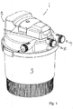
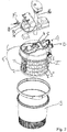
- Figs. 1-4 show a pond filter unit 1 according to the present invention.
- the pond filter 1 comprises a filter body 1.
- the filter body 2 in the pond filter unit comprises at least one or more blocks 2', 2", 2'" of flexible filter material, such as polymeric open pored foam or a flexible block of fibrous filter material that are arranged in a vessel 3.
- the one or more filter blocks 2', 2", 2'" comprises a central hole which is arranged on a central tube 4 that defines an outlet. In this way the one or more filter blocks 2, 2', 2"' are arranged to be rotatable in the vessel 3.
- the motorized cleaning unit 5 comprises a rotatable longitudinal rod 7 arranged in connection with the periphery of the filter material 2.
- the rotatable rod 7 presses against the outer surface of the one or more blocks of filter material 2.
- the rotatable rod has a profiled surface that causes a mechanical action against the outer surface of the filter blocks when the rod 5' is rotated by the motor unit 6.
- the profiled rod shown in fig. 2 comprises radially extending wings 7' that are acting against the surface of the filter 2.
- the motorized cleaning unit is controlled by means of control signals from the control unit12.
- the pond filter motorized cleaner the pond filter is equipped to provide backflushing of the filter 2.
- the backflushing means comprises a 3-way valve 8 that directs a reversed flow of pond water to a sewer when exiting the pond filter during the cleaning cycle.
- the 3-way valve 8 is valve is actuated to change the valve seat position based on control signals from the pond filter control unit 12.
- the 3-way valve 8 is preferably a motorized magnetically actuated valve.
- the pond filter unit 1 comprises a UV lamp unit 16 arranged in the central tube 4 to expose a water outlet flow to ultraviolet radiation.
- the control unit 12 is configured to control the operation of the UV lamp 16 according to input settings as described above.
- the pond filter control unit is preferably remote controllable by means of a remote control unit as described above.
- the remote control unit may provide control signals by means of a wired or a wireless connection to the pond filter control unit, preferably, by providing an on/off/dimming of the current supplied through the one or more plugs 14 as described further above, or alternatively by a 0-10 V control signal supplied through a wired connection or a wireless connection, e.g. WIFI network, the mobile phone network, internet and/ or a combination thereof.
- the remote control unit may thus be a conventional separately produced remote control unit based on short range wireless connection, in particular infrared connections.
- the remote control unit comprises a control application or program installed on a stationary or portable computer, a tablet and/or a cell phone, in particular a smart phone.
- the remote control unit is a control application installed on a e.g. mobile phone, in particular a smart phone, it becomes possible to control the pond filter and/or the one or more auxiliary devices that are connected to the one or more plugs from a remote distance as described above.
- a control unit 12 controls the operation of the pond filter unit, including the cleaning cycle of the filter 2.
- the pond filter unit further comprises one or more plugs 14 for connecting the power and/or control means of one or more auxiliary devices (not shown) via plugs 15.
- the control unit 12 of the pond filter then controls the one or more auxiliary devices based on set or preset stored input settings for each of the one or more auxiliary devices.
- the pond filter control unit 12 is configured to activate/deactivate the cleaning cycle of the pond filter unit, i.e. the motor 6 of the motorized filter cleaning unit 5 and/or the 3 way valve 8, the UV lamp 16 and/or one or more auxiliary devices, either by automated activation/deactivation by the control unit 12 and/or when a manual input is made on the remote control unit or the control buttons 12a or a touch screen display 12b on the pond filter control unit. 12.
- the input means 12a on the control unit 12 or the touch screen control display on the pond filter control unit and/or the remote control unit can also be used for changing the settings for the UV lamp as described above.
- control unit 12 may also be possible to identify in the control unit 12 that a box (not shown) with a number of identified plugs (e.g. 2, 3, 4, 5 or more separate plugs) is connected to a particular plug 14 or other on the pond filter unit 1 for allowing the control unit 12 to perform individual and/or groupwise control of each device connected to the respective plugs in the box.
- a box not shown
- a number of identified plugs e.g. 2, 3, 4, 5 or more separate plugs
- the filter cleaning cycle is preferably carried out by the control unit performing at least the following sequence:
- the pumping means (not shown) is activated for one or more predefined time intervals, e.g. 30 seconds for every 2 minutes, during the cleaning cycle to direct water to the waste water outlet 10. This may also provide a backflushing of the filter 2.
- the cleaning cycle is terminated by activating the at least one valve 8 means to direct the outlet flow of the pond filter unit from the waste water outlet 11 to the recirculation outlet 10. This will most often also mean that the pumping direction of the pump is reversed from the backflush direction to the filtering direction.
- the method for operating a pond filter also comprises that the control unit 12 controls each of the one or more auxiliary devices.
- the control of the one or more auxiliary devices are in one variant performed by controlling the power output in the plug 14 to which the additional device is connected to the pond filter 1.
- the effect of the auxiliary device can be easily adjusted by between a predefined minimum and maximum by adjusting, i.e., increasing or lowering the current supplied to the auxiliary device through the relevant plug 1 on the pond filter 1.
- the control of the one or more auxiliary devices is obtained by providing a control signal to the one or more additional device by a wired connection, such as a low voltage control, e.g. 0-10 V control signal.
- the frequency and/or duration of the cleaning cycle, the UV radiation and/or the operation of the one the control unit of the one or more auxiliary devices can easily be adjusted on a remote control unit, as described above.
- the method for operating a pond filter unit 1 comprises that the control unit 12 further controls the UV lamp unit 16 arranged to expose a water flow through the filter unit 1 based on input settings such as the of duration of the ultraviolet radiation and/or intervals between activation of UV lamp 16.
- the control regime of the UV lamp 16 may depend on whether or not a cleaning cycle is activated, the season, the temperature and similar parameters that were already described above.
- Sensors may be applied to provide input to the control unit as already explained above.
- the special function and design makes the pond filter unit 1 ideal for garden ponds, fountains, aquaculture ponds, aquaria, reservoirs and other aquatic applications.
- control unit 12 is provided without remote control means.
- control unit is controlled by means of preset settings and/or settings that are input to the control unit via the buttons 11a or a touch screen display 12b.
- Optional pump switch off or reversing pumping direction change position of the 3-way valve 8 to redirect flow from filtered water return flow outlet 10 to the waste water outlet 11.
- Starting rotation of the filter cleaning rod 7 for cleaning of filter foam plates 2, 2" etc. Optional pump switch on (if off) for backwashing, preferably in reversed flow mode.
- a Combined rotation of the rod 7 filter cleaner 5 and backwash sequence may be performed together or preferably in sequence. This sequence is preferably defined by a setting for a timer.
- the cleaning sequence is ended by changing the position of the 3-way valve 8 to redirecting the water from waste water outlet 10 to filtered water outlet 9.
- the water flow through the filter unit is reversed from backflushing direction to filtering direction. This procedure can also be applied in the remote controllable variant.
- the backwash sequence of the cleaning sequence may comprise a possibility for providing settings that identify a programmed scheduled water change at certain intervals by guiding a certain amount of water to the waste water outlet 11 while a similar amount of water is supplied to the pond from another source, e.g. common tap water supply.
- This regular renewal of water is especially important for particularly polluted environments/ponds with heavy feeding causing waste - like aquaculture or other heavily stocked ponds, or during periods with heavy rain- in the latter case to avoid flooding of the pond.
Priority Applications (7)
| Application Number | Priority Date | Filing Date | Title |
|---|---|---|---|
| EP17169016.7A EP3398433A1 (fr) | 2017-05-02 | 2017-05-02 | Filtre pour bassin et procédé pour utiliser le filtre pour bassin |
| DK18755704.6T DK3589120T3 (da) | 2017-05-02 | 2018-05-01 | Damfilter og fremgangsmåde til betjening af damfilter |
| EP18755704.6A EP3589120B1 (fr) | 2017-05-02 | 2018-05-01 | Filtre pour bassin et procédé pour utiliser le filtre pour bassin |
| CN201880029363.4A CN110582202B (zh) | 2017-05-02 | 2018-05-01 | 池塘过滤器和操作池塘过滤器的方法 |
| PCT/EP2018/061074 WO2018206342A1 (fr) | 2017-05-02 | 2018-05-01 | Filtre de bassin et procédé de fonctionnement du filtre de bassin |
| US16/607,969 US11427491B2 (en) | 2017-05-02 | 2018-05-01 | Pond filter and method for operating the pond filter |
| PL18755704T PL3589120T3 (pl) | 2017-05-02 | 2018-05-01 | Filtr stawowy i sposób działania filtra stawowego |
Applications Claiming Priority (1)
| Application Number | Priority Date | Filing Date | Title |
|---|---|---|---|
| EP17169016.7A EP3398433A1 (fr) | 2017-05-02 | 2017-05-02 | Filtre pour bassin et procédé pour utiliser le filtre pour bassin |
Publications (1)
| Publication Number | Publication Date |
|---|---|
| EP3398433A1 true EP3398433A1 (fr) | 2018-11-07 |
Family
ID=58669639
Family Applications (2)
| Application Number | Title | Priority Date | Filing Date |
|---|---|---|---|
| EP17169016.7A Withdrawn EP3398433A1 (fr) | 2017-05-02 | 2017-05-02 | Filtre pour bassin et procédé pour utiliser le filtre pour bassin |
| EP18755704.6A Active EP3589120B1 (fr) | 2017-05-02 | 2018-05-01 | Filtre pour bassin et procédé pour utiliser le filtre pour bassin |
Family Applications After (1)
| Application Number | Title | Priority Date | Filing Date |
|---|---|---|---|
| EP18755704.6A Active EP3589120B1 (fr) | 2017-05-02 | 2018-05-01 | Filtre pour bassin et procédé pour utiliser le filtre pour bassin |
Country Status (6)
| Country | Link |
|---|---|
| US (1) | US11427491B2 (fr) |
| EP (2) | EP3398433A1 (fr) |
| CN (1) | CN110582202B (fr) |
| DK (1) | DK3589120T3 (fr) |
| PL (1) | PL3589120T3 (fr) |
| WO (1) | WO2018206342A1 (fr) |
Cited By (4)
| Publication number | Priority date | Publication date | Assignee | Title |
|---|---|---|---|---|
| CN110433547A (zh) * | 2019-07-18 | 2019-11-12 | 厦门润创远工贸有限公司 | 一种可反向冲洗过滤器及其控制方法 |
| CN112715461A (zh) * | 2020-12-30 | 2021-04-30 | 梁燕 | 一种智能清洁投食免换水式水族箱 |
| CN114028869A (zh) * | 2021-11-04 | 2022-02-11 | 海梦城文化科技股份有限公司 | 一种水族馆过滤器装置 |
| ES2927786A1 (es) * | 2021-05-05 | 2022-11-10 | Tecn De Desalinizacion De Aguas S A | Filtro y método de filtrado para inactivar huevos de helmintos y ooquistes de protozoos del agua |
Families Citing this family (2)
| Publication number | Priority date | Publication date | Assignee | Title |
|---|---|---|---|---|
| US11464214B1 (en) * | 2021-03-23 | 2022-10-11 | Navpreet Singh Sethi | Periodic and automated water change device having a configurable water change schedule |
| CN114190319B (zh) * | 2021-12-06 | 2022-07-08 | 肇庆市德邦坚农业有限公司 | 一种转动式具有更换养料的池塘水循环养殖辅助机构 |
Citations (6)
| Publication number | Priority date | Publication date | Assignee | Title |
|---|---|---|---|---|
| US5730861A (en) * | 1996-05-06 | 1998-03-24 | Sterghos; Peter M. | Swimming pool control system |
| JP3045478B2 (ja) * | 1996-11-28 | 2000-05-29 | 株式会社リュウビ | 養魚用汚水ろ過装置および浄化装置 |
| JP2006026594A (ja) * | 2004-07-21 | 2006-02-02 | Masao Kirikae | 濾過装置 |
| US20090218285A1 (en) * | 2006-03-16 | 2009-09-03 | Seccua Gmbh | Controls of a filtration system |
| US20100237254A1 (en) * | 2006-04-01 | 2010-09-23 | P.W. Circuits Limited | Fluid treatment apparatus comprising ultraviolet light emitting diode |
| CN105981679A (zh) * | 2015-02-16 | 2016-10-05 | 南京莎菲特生物科技有限公司 | 智慧水族鱼缸 |
Family Cites Families (8)
| Publication number | Priority date | Publication date | Assignee | Title |
|---|---|---|---|---|
| US4676914A (en) * | 1983-03-18 | 1987-06-30 | North Coast Systems, Inc. | Microprocessor based pump controller for backwashable filter |
| GB9617482D0 (en) * | 1996-08-20 | 1996-10-02 | Bakey Michael T | Improvements in or relating to pre pump filters |
| GB0423970D0 (en) | 2004-10-28 | 2004-12-01 | Hozelock Ltd | Pond filters |
| GB2507438B (en) * | 2010-02-24 | 2014-07-16 | Interpet Ltd | A water filter |
| AU2011101664B4 (en) * | 2011-02-04 | 2012-05-03 | Waterco Limited | Water Treatment System |
| GB2498334B (en) * | 2011-12-21 | 2016-10-05 | Exel Industries Sa | Pond filters and pond filter arrangements |
| US20160279576A1 (en) | 2013-11-08 | 2016-09-29 | Nanyang Technological University | A membrane filtration module |
| MA43073A (fr) * | 2015-07-20 | 2018-05-30 | Spectrum Brands Inc | Connectivité et commande d'habitat |
-
2017
- 2017-05-02 EP EP17169016.7A patent/EP3398433A1/fr not_active Withdrawn
-
2018
- 2018-05-01 CN CN201880029363.4A patent/CN110582202B/zh active Active
- 2018-05-01 EP EP18755704.6A patent/EP3589120B1/fr active Active
- 2018-05-01 DK DK18755704.6T patent/DK3589120T3/da active
- 2018-05-01 PL PL18755704T patent/PL3589120T3/pl unknown
- 2018-05-01 WO PCT/EP2018/061074 patent/WO2018206342A1/fr active Application Filing
- 2018-05-01 US US16/607,969 patent/US11427491B2/en active Active
Patent Citations (6)
| Publication number | Priority date | Publication date | Assignee | Title |
|---|---|---|---|---|
| US5730861A (en) * | 1996-05-06 | 1998-03-24 | Sterghos; Peter M. | Swimming pool control system |
| JP3045478B2 (ja) * | 1996-11-28 | 2000-05-29 | 株式会社リュウビ | 養魚用汚水ろ過装置および浄化装置 |
| JP2006026594A (ja) * | 2004-07-21 | 2006-02-02 | Masao Kirikae | 濾過装置 |
| US20090218285A1 (en) * | 2006-03-16 | 2009-09-03 | Seccua Gmbh | Controls of a filtration system |
| US20100237254A1 (en) * | 2006-04-01 | 2010-09-23 | P.W. Circuits Limited | Fluid treatment apparatus comprising ultraviolet light emitting diode |
| CN105981679A (zh) * | 2015-02-16 | 2016-10-05 | 南京莎菲特生物科技有限公司 | 智慧水族鱼缸 |
Cited By (6)
| Publication number | Priority date | Publication date | Assignee | Title |
|---|---|---|---|---|
| CN110433547A (zh) * | 2019-07-18 | 2019-11-12 | 厦门润创远工贸有限公司 | 一种可反向冲洗过滤器及其控制方法 |
| CN110433547B (zh) * | 2019-07-18 | 2023-09-01 | 厦门润创远工贸有限公司 | 一种可反向冲洗过滤器及其控制方法 |
| CN112715461A (zh) * | 2020-12-30 | 2021-04-30 | 梁燕 | 一种智能清洁投食免换水式水族箱 |
| ES2927786A1 (es) * | 2021-05-05 | 2022-11-10 | Tecn De Desalinizacion De Aguas S A | Filtro y método de filtrado para inactivar huevos de helmintos y ooquistes de protozoos del agua |
| CN114028869A (zh) * | 2021-11-04 | 2022-02-11 | 海梦城文化科技股份有限公司 | 一种水族馆过滤器装置 |
| CN114028869B (zh) * | 2021-11-04 | 2023-01-03 | 海梦城文化科技股份有限公司 | 一种水族馆过滤器装置 |
Also Published As
| Publication number | Publication date |
|---|---|
| WO2018206342A1 (fr) | 2018-11-15 |
| DK3589120T3 (da) | 2020-09-21 |
| US20210101816A1 (en) | 2021-04-08 |
| CN110582202A (zh) | 2019-12-17 |
| EP3589120B1 (fr) | 2020-08-05 |
| US11427491B2 (en) | 2022-08-30 |
| EP3589120A1 (fr) | 2020-01-08 |
| PL3589120T3 (pl) | 2020-11-30 |
| CN110582202B (zh) | 2022-05-24 |
Similar Documents
| Publication | Publication Date | Title |
|---|---|---|
| EP3589120B1 (fr) | Filtre pour bassin et procédé pour utiliser le filtre pour bassin | |
| US20170049082A1 (en) | Inland aquaponics system using biofloc technology | |
| JP6176508B2 (ja) | 水循環ポンプ用の自己洗浄プレフィルタ | |
| CN106082533B (zh) | 一种景观鱼池净化处理系统及处理方法 | |
| US20060011528A1 (en) | Animal water tub | |
| KR102057934B1 (ko) | 무선전력을 이용한 동물용 정수기 | |
| KR20150001800U (ko) | 어항용 부유 이물질 정수기 | |
| CN211185501U (zh) | 水产批发养殖供水及废水收集循环系统 | |
| CN205585114U (zh) | 一种鱼缸自助管理系统 | |
| CN205667226U (zh) | 一种可远程控制的智能生态鸟笼 | |
| CN210094384U (zh) | 鱼缸自动净化设备 | |
| CN110367182A (zh) | 一种全自动水族养殖生态净化系统及其运行控制方法 | |
| CN215224027U (zh) | 一种智能鱼池固液分离生化一体机 | |
| CN211932132U (zh) | 一种可净化过滤水的水族箱 | |
| CN212937410U (zh) | 一种全程循环水养殖系统 | |
| CN210987634U (zh) | 便携式喂水器 | |
| CN105753269A (zh) | 一种低成本园林式景观水循环处理系统 | |
| CN112167154A (zh) | —种水循环的小龙虾养殖设备 | |
| CN213680279U (zh) | 一种物理生化一体式智能全自动观赏鱼池过滤装置 | |
| CN110589990A (zh) | 一种智能生态水族生物箱 | |
| KR200479838Y1 (ko) | 축사용 순환 음수라인 장치 | |
| CN216492697U (zh) | 动物饮水机和过滤装置以及过滤控制系统 | |
| US20120234744A1 (en) | Filtration system | |
| CN215712377U (zh) | 一种过滤砂缸及具有过滤砂缸的养殖系统 | |
| CN214593609U (zh) | 水产养殖用水循环系统 |
Legal Events
| Date | Code | Title | Description |
|---|---|---|---|
| PUAI | Public reference made under article 153(3) epc to a published international application that has entered the european phase |
Free format text: ORIGINAL CODE: 0009012 |
|
| AK | Designated contracting states |
Kind code of ref document: A1 Designated state(s): AL AT BE BG CH CY CZ DE DK EE ES FI FR GB GR HR HU IE IS IT LI LT LU LV MC MK MT NL NO PL PT RO RS SE SI SK SM TR |
|
| AX | Request for extension of the european patent |
Extension state: BA ME |
|
| STAA | Information on the status of an ep patent application or granted ep patent |
Free format text: STATUS: THE APPLICATION IS DEEMED TO BE WITHDRAWN |
|
| 18D | Application deemed to be withdrawn |
Effective date: 20190508 |