EP3398236B1 - Procédé de commande de parc d'éoliennes - Google Patents
Procédé de commande de parc d'éoliennes Download PDFInfo
- Publication number
- EP3398236B1 EP3398236B1 EP16819808.3A EP16819808A EP3398236B1 EP 3398236 B1 EP3398236 B1 EP 3398236B1 EP 16819808 A EP16819808 A EP 16819808A EP 3398236 B1 EP3398236 B1 EP 3398236B1
- Authority
- EP
- European Patent Office
- Prior art keywords
- power
- losses
- value
- wind
- power plant
- Prior art date
- Legal status (The legal status is an assumption and is not a legal conclusion. Google has not performed a legal analysis and makes no representation as to the accuracy of the status listed.)
- Active
Links
- 238000000034 method Methods 0.000 title claims description 20
- 238000004519 manufacturing process Methods 0.000 claims description 40
- 238000004891 communication Methods 0.000 claims description 32
- 230000006870 function Effects 0.000 claims description 30
- 238000005259 measurement Methods 0.000 claims description 29
- 230000008878 coupling Effects 0.000 claims description 10
- 238000010168 coupling process Methods 0.000 claims description 10
- 238000005859 coupling reaction Methods 0.000 claims description 10
- 238000004590 computer program Methods 0.000 claims description 8
- 238000012545 processing Methods 0.000 claims description 4
- 238000012546 transfer Methods 0.000 claims description 3
- 230000004044 response Effects 0.000 description 16
- 230000003750 conditioning effect Effects 0.000 description 13
- 230000009471 action Effects 0.000 description 12
- 238000004364 calculation method Methods 0.000 description 12
- 230000008859 change Effects 0.000 description 11
- 238000010586 diagram Methods 0.000 description 11
- 238000001914 filtration Methods 0.000 description 10
- 230000010355 oscillation Effects 0.000 description 9
- 101100381996 Saccharomyces cerevisiae (strain ATCC 204508 / S288c) BRO1 gene Proteins 0.000 description 8
- 230000001052 transient effect Effects 0.000 description 8
- 230000001934 delay Effects 0.000 description 7
- 238000010248 power generation Methods 0.000 description 6
- 238000005070 sampling Methods 0.000 description 6
- 230000008901 benefit Effects 0.000 description 5
- 238000004422 calculation algorithm Methods 0.000 description 5
- 230000001276 controlling effect Effects 0.000 description 5
- 239000000243 solution Substances 0.000 description 5
- 238000009499 grossing Methods 0.000 description 4
- 238000002347 injection Methods 0.000 description 3
- 239000007924 injection Substances 0.000 description 3
- 238000012986 modification Methods 0.000 description 3
- 230000004048 modification Effects 0.000 description 3
- 230000001681 protective effect Effects 0.000 description 3
- 238000004088 simulation Methods 0.000 description 3
- 230000007423 decrease Effects 0.000 description 2
- 230000000694 effects Effects 0.000 description 2
- 238000004146 energy storage Methods 0.000 description 2
- 230000035484 reaction time Effects 0.000 description 2
- 238000011084 recovery Methods 0.000 description 2
- 230000001105 regulatory effect Effects 0.000 description 2
- 230000001360 synchronised effect Effects 0.000 description 2
- 230000001960 triggered effect Effects 0.000 description 2
- 230000006399 behavior Effects 0.000 description 1
- 230000033228 biological regulation Effects 0.000 description 1
- 230000005540 biological transmission Effects 0.000 description 1
- 239000003990 capacitor Substances 0.000 description 1
- 230000001143 conditioned effect Effects 0.000 description 1
- 238000013016 damping Methods 0.000 description 1
- 230000003111 delayed effect Effects 0.000 description 1
- 230000001419 dependent effect Effects 0.000 description 1
- 230000003287 optical effect Effects 0.000 description 1
- 230000035515 penetration Effects 0.000 description 1
- 238000011144 upstream manufacturing Methods 0.000 description 1
Images


Classifications
-
- F—MECHANICAL ENGINEERING; LIGHTING; HEATING; WEAPONS; BLASTING
- F03—MACHINES OR ENGINES FOR LIQUIDS; WIND, SPRING, OR WEIGHT MOTORS; PRODUCING MECHANICAL POWER OR A REACTIVE PROPULSIVE THRUST, NOT OTHERWISE PROVIDED FOR
- F03D—WIND MOTORS
- F03D7/00—Controlling wind motors
- F03D7/02—Controlling wind motors the wind motors having rotation axis substantially parallel to the air flow entering the rotor
- F03D7/04—Automatic control; Regulation
- F03D7/042—Automatic control; Regulation by means of an electrical or electronic controller
- F03D7/048—Automatic control; Regulation by means of an electrical or electronic controller controlling wind farms
-
- H—ELECTRICITY
- H02—GENERATION; CONVERSION OR DISTRIBUTION OF ELECTRIC POWER
- H02J—CIRCUIT ARRANGEMENTS OR SYSTEMS FOR SUPPLYING OR DISTRIBUTING ELECTRIC POWER; SYSTEMS FOR STORING ELECTRIC ENERGY
- H02J3/00—Circuit arrangements for ac mains or ac distribution networks
- H02J3/38—Arrangements for parallely feeding a single network by two or more generators, converters or transformers
- H02J3/381—Dispersed generators
-
- H—ELECTRICITY
- H02—GENERATION; CONVERSION OR DISTRIBUTION OF ELECTRIC POWER
- H02J—CIRCUIT ARRANGEMENTS OR SYSTEMS FOR SUPPLYING OR DISTRIBUTING ELECTRIC POWER; SYSTEMS FOR STORING ELECTRIC ENERGY
- H02J3/00—Circuit arrangements for ac mains or ac distribution networks
- H02J3/38—Arrangements for parallely feeding a single network by two or more generators, converters or transformers
- H02J3/46—Controlling of the sharing of output between the generators, converters, or transformers
- H02J3/48—Controlling the sharing of the in-phase component
-
- F—MECHANICAL ENGINEERING; LIGHTING; HEATING; WEAPONS; BLASTING
- F03—MACHINES OR ENGINES FOR LIQUIDS; WIND, SPRING, OR WEIGHT MOTORS; PRODUCING MECHANICAL POWER OR A REACTIVE PROPULSIVE THRUST, NOT OTHERWISE PROVIDED FOR
- F03D—WIND MOTORS
- F03D7/00—Controlling wind motors
- F03D7/02—Controlling wind motors the wind motors having rotation axis substantially parallel to the air flow entering the rotor
- F03D7/028—Controlling wind motors the wind motors having rotation axis substantially parallel to the air flow entering the rotor controlling wind motor output power
- F03D7/0284—Controlling wind motors the wind motors having rotation axis substantially parallel to the air flow entering the rotor controlling wind motor output power in relation to the state of the electric grid
-
- F—MECHANICAL ENGINEERING; LIGHTING; HEATING; WEAPONS; BLASTING
- F05—INDEXING SCHEMES RELATING TO ENGINES OR PUMPS IN VARIOUS SUBCLASSES OF CLASSES F01-F04
- F05B—INDEXING SCHEME RELATING TO WIND, SPRING, WEIGHT, INERTIA OR LIKE MOTORS, TO MACHINES OR ENGINES FOR LIQUIDS COVERED BY SUBCLASSES F03B, F03D AND F03G
- F05B2220/00—Application
- F05B2220/70—Application in combination with
- F05B2220/706—Application in combination with an electrical generator
-
- F—MECHANICAL ENGINEERING; LIGHTING; HEATING; WEAPONS; BLASTING
- F05—INDEXING SCHEMES RELATING TO ENGINES OR PUMPS IN VARIOUS SUBCLASSES OF CLASSES F01-F04
- F05B—INDEXING SCHEME RELATING TO WIND, SPRING, WEIGHT, INERTIA OR LIKE MOTORS, TO MACHINES OR ENGINES FOR LIQUIDS COVERED BY SUBCLASSES F03B, F03D AND F03G
- F05B2270/00—Control
- F05B2270/30—Control parameters, e.g. input parameters
- F05B2270/337—Electrical grid status parameters, e.g. voltage, frequency or power demand
-
- H—ELECTRICITY
- H02—GENERATION; CONVERSION OR DISTRIBUTION OF ELECTRIC POWER
- H02J—CIRCUIT ARRANGEMENTS OR SYSTEMS FOR SUPPLYING OR DISTRIBUTING ELECTRIC POWER; SYSTEMS FOR STORING ELECTRIC ENERGY
- H02J2300/00—Systems for supplying or distributing electric power characterised by decentralized, dispersed, or local generation
- H02J2300/20—The dispersed energy generation being of renewable origin
- H02J2300/28—The renewable source being wind energy
-
- Y—GENERAL TAGGING OF NEW TECHNOLOGICAL DEVELOPMENTS; GENERAL TAGGING OF CROSS-SECTIONAL TECHNOLOGIES SPANNING OVER SEVERAL SECTIONS OF THE IPC; TECHNICAL SUBJECTS COVERED BY FORMER USPC CROSS-REFERENCE ART COLLECTIONS [XRACs] AND DIGESTS
- Y02—TECHNOLOGIES OR APPLICATIONS FOR MITIGATION OR ADAPTATION AGAINST CLIMATE CHANGE
- Y02E—REDUCTION OF GREENHOUSE GAS [GHG] EMISSIONS, RELATED TO ENERGY GENERATION, TRANSMISSION OR DISTRIBUTION
- Y02E10/00—Energy generation through renewable energy sources
- Y02E10/70—Wind energy
- Y02E10/72—Wind turbines with rotation axis in wind direction
-
- Y—GENERAL TAGGING OF NEW TECHNOLOGICAL DEVELOPMENTS; GENERAL TAGGING OF CROSS-SECTIONAL TECHNOLOGIES SPANNING OVER SEVERAL SECTIONS OF THE IPC; TECHNICAL SUBJECTS COVERED BY FORMER USPC CROSS-REFERENCE ART COLLECTIONS [XRACs] AND DIGESTS
- Y02—TECHNOLOGIES OR APPLICATIONS FOR MITIGATION OR ADAPTATION AGAINST CLIMATE CHANGE
- Y02E—REDUCTION OF GREENHOUSE GAS [GHG] EMISSIONS, RELATED TO ENERGY GENERATION, TRANSMISSION OR DISTRIBUTION
- Y02E10/00—Energy generation through renewable energy sources
- Y02E10/70—Wind energy
- Y02E10/76—Power conversion electric or electronic aspects
Definitions
- aspects of the invention relate to the control of a wind power plant, particularly in connection with power boosting or fast increase of active power production.
- Inertia response is a functionality where the power is boosted from the normal production for a short period of time, i.e. power delivered to the electrical grid is increased.
- the boost of power function may be available at all wind speeds. For very low wind speeds, the power boost may be rather reduced.
- a boost power should be provided upon request.
- the wind power plant may be specified that whenever the production from the wind power plant is above 25 % of rated power, the wind power plant must be able to deliver a power boost of 5-10% of rated power for a given time period, e.g. up to 10 seconds.
- the grid code may also specify requirements for the recovery period.
- after the boost it may be specified that the wind turbine must have returned to normal operation after 2 minutes, and that during the recovery phase the power produced by the wind turbine should remain within 80% of available power.
- EP2384540 discloses a power generation system.
- the power generation system includes a power generation unit operable to supply electrical power to an utility system; a synchronous machine coupled to the utility system; a grid measurement device for measuring the current and power exchanged between the synchronous machine and the utility system; a controller for adjusting the output power of the power generation unit as a function of the power and current measured by the grid measurement device; and a communication link between the grid measurement device, the controller and/or the power generation unit.
- the power generation unit is configured to provide current and power to the utility system as a function of the power and current measured by the grid measurement device.
- Embodiments of the present invention provide a solution to circumvent at least some of the problems with the prior art.
- a first aspect of the invention relates to a method for controlling a wind power plant comprising a plurality of wind turbine generators.
- the method comprises:
- a second aspect of the invention relates to an active power controller for controlling a wind power plant.
- the wind power plant comprises a plurality of wind turbine generators.
- the controller comprises: a module for deriving an estimated value for electrical losses in the wind power plant; a module for deriving a measured value for electrical losses in the wind power plant, based on a difference between an aggregated power production (Pprod) from the plurality of wind turbine generators and a power measurement (Pmeas) at a point of common coupling; and a regulator arranged to apply the estimated value for electrical losses and the measured value for electrical losses in an active power control loop, the active power control loop being arranged to control an active power production of the wind power plant at the point of common coupling.
- Pprod aggregated power production
- Pmeas power measurement
- a third aspect of the present invention relates to a computer program product loadable into an internal memory of a processing device, the computer program product comprising software code portions for performing in the processing device the steps of the method according to the first aspect or any of the embodiments of the method.
- a fourth aspect of the invention relates to a wind power plant comprising a plurality of wind turbine generators and an active power controller according to the second aspect above.
- FIG 1 shows a wind turbine generator (WTG) 100 comprising a tower 101 and a rotor 102.
- the rotor comprises three rotor blades 103.
- the number of blades may vary, and there may be two, four or even more blades.
- the rotor is connected to a nacelle 104, which is mounted on top of the tower 101, and is arranged to drive an electrical generator situated inside the nacelle.
- the rotor 102 is rotatable by action of the wind.
- the wind-induced rotational energy of the rotor blades 103 is transferred via a shaft to the electrical generator.
- the WTG 100 is capable of converting kinetic energy of the wind into mechanical energy by means of the rotor blades and, subsequently, into electric power by means of the electrical generator.
- the electrical layout of the WTG may in addition to the electrical generator include a power converter.
- the power converter is connected in series between the electrical generator and the electrical grid for converting the variable frequency generator AC power into a grid frequency AC power to be injected into the utility/electrical grid.
- the electrical generator is via the power converter controllable to produce a power corresponding to a power request.
- the blades 103 can be pitched in order to alter the aerodynamic properties of the blades, e.g. in order to maximize uptake of the wind energy.
- the blades are pitched by a pitch system, which includes actuators for pitching the blades dependent on a pitch request.
- a WTG is, in normal operation, set to capture as much power from the wind, at any given wind speed. This works as long as the power production is below the rated power limit for the wind turbine, i.e. partial load operation.
- the WTG has to pitch the blades 103, so the energy captured is stable at rated power, even if the wind is well above rated wind speed.
- a wind power plant comprises a plurality WTGs controlled by a power plant controller (PPC) and interconnection infrastructure.
- FIG 2 shows an example of a generic WPP architecture with a plurality of WTGs, a collection grid with a MV collection bus, a transformer (TRF).
- TRF transformer
- PoM point of measurement
- PCC Point of Common Coupling
- the measurements obtained at the PoM are communicated to the PPC and optionally also to a SCADA system.
- the SCADA is optional and is not necessarily interacting with embodiments of the present invention.
- the PPC controls the WTGs accordingly.
- Further optional equipment is also shown, such as a STATCOM, MSU (Mechanically Switched Unit, wherein the unit can be either capacitors or inductors), ES (Energy Storage) all used for improving power quality and stability.
- the Power Plant Controller (PPC) in a control system within a Wind Power Plant (WPP) has among others the responsibility to control Active Power (P) and Reactive Power (Q) at the Point of Interconnection (P0I) with the Utility Grid (UG).
- the P and Q quantities are the means by which other system parameters can be influenced, such as the grid frequency (f) and voltage (V).
- the controller structure has as inner loops the P and Q control, and has as outer loops the f and V control.
- the PPC is also responsible for other WPP functionalities, which are required either by the Transmission System Operator (TSO) or by the WPP owner.
- TSO Transmission System Operator
- the Active Power control loop is responsible for controlling P at the point of interconnection.
- This inner loop can be used to influence the grid frequency, by adding appropriate external control loops (primary frequency regulation, fast frequency response and inertia emulation response).
- Power Oscillation Damping can be achieved as well by adding an appropriate external control loop.
- Active Power Loop may comprise all controllers affecting the active power injection at the PCC (e.g. frequency controller, inertia emulation controller, output ramp rate limiter, active power dispatcher, etc.). In this document only the core (inner) loop of the APL is considered (i.e. what is called Active Power Controller).
- Active Power Controller is a control structure within the PPC which is aimed to regulate the active power injection at the PCC according to specified requirements, while ensuring stable operation of the WPP with regard to active power.
- APC receives a set-point which represents the active power injection that is requested at the PCC.
- This request can be issued by the system operator (e.g. fixed amount of active power) or by other "upstream" control loops (e.g. variable amount of active power issued by the frequency controller).
- APC outputs a power reference for the WPP which goes through the Ramp Rate Limiter and finally through the Active Power Dispatcher in order to be shared among the WTGs.
- an active power controller consists of two main signal paths, namely: The "forward" path, which builds up the reference to be sent to the WTGs by summing up or subtracting other signals (e.g. power set-point, power measurement, feed-forward terms).
- the "forward" path which builds up the reference to be sent to the WTGs by summing up or subtracting other signals (e.g. power set-point, power measurement, feed-forward terms).
- the “feedback” path which usually contains measurements from the electrical circuit (e.g. active power P at POI, aggregated sum of active power P production from WTGs).
- the system Due to sampling and communication delays in the forward and feedback path, the system can be unstable. In the same time, the controller response quality can be poor.
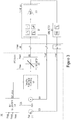
- Figure 3 shows the structure of a P loop for an embodiment.
- the loop comprises a proportional controller 332 with a unity gain, with a feed-forward of the WTGs power production 304.
- the reference power sent to the WTGs is in fact the power set-point plus the measured losses in the system. Therefore, in order to issue a correct set-point, the power losses in the system must be correctly measured. This implies small and similar communication delays in the measured power at the POI and the measured WTGs power production.
- the reference power signal 308 sent to the WTGs is conditioned in the "Total Power Signal Conditioning" block 302.
- This block performs two main tasks: If the power error 306 is within a specified small value (i.e. in other words, if the measured power is close to the power set-point), the algorithm detects if there are any oscillations in the reference power sent to the WTGs and, in case there are oscillations it reduces the oscillations by altering (e.g. reducing) the WTGs' power reference change.
- the WTGs' power reference is not altered.
- the algorithm verifies if the reference power 308 sent to the WTGs has the correct trend (i.e. increase or decrease - depending on the power error sign. If the trend is not correct, the WTGs' power reference is kept to the value on the previous time step.
- the wrong trend in the WTGs' reference power can be due to the communication delay in the WTGs' power production, which is larger than the communication delay in the measured power at the POI.
- the wrong trend can also be if the delay in measured power at POI is larger than delay in the reported WTGs' production. Basically as long as there is a communication delay between the two feedbacks, there can be a wrong trend in the WTGs' reference.
- the Balance of Plant Estimator 301 uses:
- the WPP is simulated using simulation tools in order to determine - among other - the power losses in the system as a function of the active power level, reactive power level, voltage level.
- Stability of the aforementioned control loop is given mainly by the relatively high sample time (and to some extent by the communication delays in the feedback).
- the "Total WTG Power Signal Conditioning" block 302 is contributing as well to the stability, by means of the actions described above. However, this cannot be considered as closed loop stability, given its non-linear characteristic.
- the control loop is stable even without the action of the "Total WTG Power Signal Conditioning" block.
- the sampling time is reduced (e.g. 50 ms)
- An advantage of the embodiments which uses BoP loss estimation is that system decreases the response time.
- the response time requirements in some countries ask for reaction time of less than 200 ms, and therefore can a feed-forward of the losses improve the system response.
- the sampling time is significantly reduced and the communication delays in the forward path as well as in the measurement path are reduced as well.
- the regulator can in general be included in:
- the regulator can perform the following functions:
- the regulator can have the following inputs:
- the output of the regulator is a regulated / filtered signal that can be used to generate correct / convenient power references to the WTGs according to the desired output at POI.
- Regulator initialization can be obtained by means of a system that uses a set of information /inputs available in the controller in order to generate the aforementioned inputs for the regulator.
- the initialization system 403 can decide which input is provided to the regulator (e.g. the measured power losses, the estimated power losses, the power error/change, the estimated power error/change, etc.), when this input is changed, what is the value to which the input is initialized, etc.
- the information / inputs used by the initialization function 403 can be as follows:
- Power loss estimation can be obtained by means of a system that uses a set of information / inputs available in the controller in order to generate an approximation of the losses in the system for specific operating points (voltage, active and reactive power levels, temperature, current, etc.).
- the estimated power losses can be used to initialize the output of the regulator in such a way that a correct / convenient power set-point is provided to the WTGs, according to the desired output at POI during steady state or transient operation.
- the following information / inputs can be requested by the power loss estimation function:
- the power loss estimation function can be built in several ways (using real system measurements, simulation results, or other calculation means), for example:
- the reference power sent to the WTGs is the sum between the power set-point (Pset) and the measured power losses (Plosses).
- the Power loop is arranged with access to the measured power losses in the system (the WTGs reference power is formed by the power set-point plus the system's filtered measured losses), the data is communicated and discretized in block 412 and 413. In this way the LPF 404 can be added in the closed loop increasing its stability.
- the LPF 404 performs two main actions:
- Figure 4 shows a diagram of the active power loop for an embodiment which is a variation of a Proportional Controller with filtering of measured power losses
- Figure 5 shows a diagram of the active power loop for a second embodiment which is a variation of a Proportional Controller with filtering of measured power losses - and power signal conditioning in a forward path.
- the "LPF Initialization & Input Selection Logic Block” 403 is responsible for deciding which signal should be used as input to the "1st order LPF2" block 404, namely the estimated power losses or the measured power losses.
- the logic used for switching between the two signals is as follows: The estimated power losses and the measured power losses are compared to each other. If the difference between them is bigger than a user defined value, it means there is a transient situation in the system. For the reasons stated a few lines above (i.e. during certain type of transients), it means the system should choose as input to the "1st order LPF2" block 404 the estimated system losses.
- the comparison is done in the form of a logic function, which can output two values, namely 0 (when the difference between them is bigger than a user-defined value) or 1 (when the difference between them is smaller than a user defined value).
- the output of this logic function is used as input to the "set" pin of a "Set / Reset” function.
- the power set-point is evaluated to check if there are power set-point changes. This is done by comparing its "present" value with the value at the previous state. The comparison is done in the form of a logic function which can output two values, namely 0 (when the two values are not equal) or 1 (when the two values are equal). This output is used in several ways:
- the "Set” input is triggered and the output of the block will be set to 1 (i.e. the estimated losses in the system will be used as input to the "1st order LPF2" block).
- the "Reset” input is triggered and the output of the block will be set to 0 (i.e. i.e. the measured losses in the system will be used as input to the "1st order LPF2" block). This ensures that the input to the "1st order LPF2" block 404 during output disturbances is the measured power losses signal.
- the "BOP Calculation" block 401 is responsible for estimating the power losses in the system corresponding to a certain power set-point.
- This block can be a lookup table or it can be a set of transfer functions which take as inputs the voltage and reactive power as well as the power set-point.
- the embodiment of Figure 4 is one example of how the "Balance of Plant Estimator” (i.e. power loss estimator) can be used in tandem with a “regulator” (e.g. the LPF) to improve the active power loop performance.
- a “regulator” e.g. the LPF
- the LPF 404 is initialized to the calculated losses 401 (i.e. calculated by the Balance of Plant Estimator), this is done in block 403. This is preferred since the actual measured losses are not correct during transients - due to physical limitations of the measurement circuit. In other words, if the actual measured losses are used in the controller during transients, the power set-point will be incorrectly calculated.
- the output of block 401 is limited in block 402, the limit in set by Ploss_max variable.
- the output of the LPF filter 404 is added 406 to the power setpoint (as shown in the equations above).
- the power setpoint is then limited by another limiter 407 and a further regulator 408 controls the power loop, before sending the set points to the WTGs there is a ramp rate limiter 409, which ensures that change in set point to the WTGs are limited.
- the signals in and out of the PPC are communicated via a communication block 410, with a set of discrete blocks 411, 412, 413.
- a grid meter 420 measures electrical parameters at a point of interest, which could be the point of common coupling.
- the WTGs and additional component, i.e. the plant are represented in block 430.
- the controller in Figure 4 performs better than the one shown in Figure 3 . Moreover, the controller provides continuous closed-loop stability in steady state operation.
- the embodiment of Figure 4 uses a system that comprises a regulator 404, e.g. low pass filter (LPF) or a different controller structure that performs the same functionality, which can be initialized (i.e. forced to output a convenient value at convenient times) based on information / signals available in the controller (e.g. measurements, algorithms, etc.) in order to contribute to the overall controller response quality and controller closed loop stability.
- a regulator 404 e.g. low pass filter (LPF) or a different controller structure that performs the same functionality, which can be initialized (i.e. forced to output a convenient value at convenient times) based on information / signals available in the controller (e.g. measurements, algorithms, etc.) in order to contribute to the overall controller response quality and controller closed loop stability.
- LPF low pass filter
- the encircled area 460 in Figure 4 shows the Power loss system with filter 404.
- the proportional controller also includes filtering of measured power losses, and power signal conditioning in a forward path.
- the LPF is used as described for the previous embodiment, however the functionality of the "LPF Initialization" block 503 has been simplified, compared to block 403 of Figure 4 .
- the purpose of block 503 is to initialize the filter with an initializing value each time the power set-point is changed.
- the "Total WTG Power Signal Conditioning" 515 together with the "LPF Initialization” block 503 ensures a correct operation of the system.
- the "Total WTG Power Signal Conditioning” 515 is by passed and the control stability of the system is ensured by the action of the LPF block 508.
- the "Total WTG Power Signal Conditioning" block 515 ensures the system not to get into situations where power is lost due to wrong estimation of the power losses. In other words, no matter how bad the "BoP Calculation" block 501 estimates the losses in the system, the power error will converge to zero very fast and the "Total WTG Power Signal Conditioning" block 515 will be bypassed.
- the third embodiment is an improved version of the second embodiment, and is the preferred embodiment.
- the main benefit of this embodiment is that it simplifies a lot the Active Power Controller's 700 structure, by allowing removal of the regulator's initialization logic as well as the "Total WTG Power Signal Conditioning" block 515.
- the main idea is to use the "BoP Estimation" block 701 at all times, instead of using it only at discrete times, in the previous embodiments the BoP loss calculation is used in discrete times (i.e. when certain conditions are met - such as power set-point change - the value calculated by "BoP Estimation” is used by the LPF 404, 504 to initialize the LPF value). So initialization only happens in a single sample when the condition is met.
- the estimated BoP losses 751 are subtracted 752 from the measured losses 701, which passed through a saturation block 702 before subtraction in block 752, and the result is filtered using a low pass filter regulator 704. In the same time, the estimated BoP losses 751 are summed 705 with the output of the low pass filter regulator.
- the low pass filter regulator 704 will have to act only on the difference between the measure losses and estimated losses. If the BoP estimation is accurate, it means the low pass filter action is minimized.
- the regulator 704 can as in the previous embodiments, be any kind of regulator that can provide the filtering function.
- the APC 700 consists of five (5) main blocks:
- the APC contains two saturation blocks 702, 707 which are used for protective reason (i.e. Power Losses Saturation and Power Reference Saturation).
- the 1st order LPF block 704 provides a filtering function of the signal and has the role to ensure stability of the control loop. As can be noticed in the diagram, the filter only acts on the difference between the measured active power losses and the estimated active power losses 752. In this way the controller speed can increase, given the estimated losses 751 are accurate (e.g. for very accurate active power loss estimation, the filter is effective only during transients).
- the Calculation of P losses block 701 is responsible for measuring the active power losses in the system (between the WTG active power production measurement and PCC active power production measurement).
- the P Losses block 701 is responsible for calculating the losses in the system as the difference between the measured power at the PCC and the total power production of the WTGs. Active power production from WTGs that have lost communication is taken into account in order to allow fall-back strategies.
- the total power production of the WPP signal i.e. Pprod
- Pmeas the measured power at the PCC signal
- Figure 7 shows a diagram of the active power loop for an embodiment, without loss of communication features.
- the active power production from WTGs that have lost communication with the PPC is taken into account when calculating the losses.
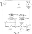
- Figure 8 shows a diagram of the active power loop for an embodiment, with loss of communication features.
- the Calculation of Pprod from WTGs with No communication block 754 is responsible for calculating the active power production from WTGs that have lost communication with the PPC.
- the active power production from WTGs that have lost communication with the PPC is subtracted in a feed forward loop, thereby compensating the active power controller.
- the subtraction is because the WTGs that have no communication will not be able to receive set-points, so the reference to be dispatched should be less with the amount that cannot be sent to the WTGs (i.e. basically the measured production from these WTGs with no communication to PPC)
- the BoP Estimation1 751 and BoP Estimation2 753 blocks are responsible for estimating the losses of the WPP collection grid, but also the losses inside the WTGs.
- losses inside the WTGs it is meant the losses which occur after the power measurement in the WTG, often the losses in the trafo, switch gear and cables on the medium voltage side of the trafo.
- One of the blocks 751 is estimating the losses based on the power reference set-point and is used for increasing the controller's speed.
- the other 753 is estimating the losses based on the power measurement at the PCC and is used for estimating the power production from WTGs that have lost communication with the PPC.
- the Perror Calculation block calculates the controller's power error signal, as the difference between the controller's power setpoint and the measured power at the point of interconnection. This is to be used by other controllers inside the PPC.
- the Power Losses Saturation 702 and Power Reference Saturation 707 blocks have the role to protect the controller from experiencing unreasonable signal values, e.g. active power losses limited between zero and a maximum value.
- the Power Losses Saturation block 702 as a protective saturation function applied to the signal entering the 1 st order LPF block 704.
- the lower limit of this saturation function must be set to zero (0) and the upper limit must be set to the maximum active power losses that can occur in the WPP (between the WTG active power production measurement and PCC active power production measurement).
- the 1 st order LPF filtering function block 704 has the main role to bring stability to the control loop. As it was explained previously, the filter only acts on the difference between the measured active power losses and the estimated active power losses. In this way the controller speed can increase, given the loss estimation is accurate.
- Embodiments of the invention are not limited to use a 1 st order LPF filter, but many other regulators can be used in the loop.
- the Power Reference Saturation block 707 acts as a protective saturation function applied to the output signal of the Active Power Controller block 700.
- the lower limit of this saturation function must be set to the minimum active power value and the upper limit must be set to the maximum allowable power that can be produced by the WPP (including in over-boost condition).
- BoP Loss Estimation function is based on second order functions which take as argument the active power level for which the collection grid losses and WTG losses must be estimated. This second order function can be obtained by means of electrical predesign studies.
- the BoP Loss Estimation block is built such that a plurality of power loss curves can be implemented for different conditions of voltage level and reactive power level. In this way the controller can choose one of the curves, based on the actual conditions in the collection grid.
- the power loss curves are predefined by simulations.
- the power loss curves are generated in a routine based learning algorithm, thereby learning the APC 700 adaptively the data of the plant.
- the Calculation of Pprod from WTGs with No Communication block 754 is responsible for calculating the active power production from WTGs that have lost communication with the PPC.
- the calculation is based on the active power measurement at the PCC, the reported active power production from WTGs and the estimated active power losses based on the active power measurement at the PCC.
- the calculation returns a value bigger than zero (0) only when the communication loss is detected.
- the limits must be set between zero (0) and the maximum losses level that can occur in the WPP (between the WTGs active power production measurement and PCC active power production measurement).
- the limits must be set between zero (0) and the maximum allowable power that can be produced by the WPP (including in over-boost condition).
- Embodiments of invention can be implemented by means of electronic hardware, software, firmware or any combination of these.
- Software implemented embodiments or features thereof may be arranged to run on one or more data processors and/or digital signal processors.
- Software is understood as a computer program or computer program product which may be stored/distributed on a suitable computer-readable medium, such as an optical storage medium or a solid-state medium supplied together with or as part of other hardware, but may also be distributed in other forms, such as via the Internet or other wired or wireless telecommunication systems.
- the computer-readable medium may be a non-transitory medium.
- the computer program comprises software code portions for performing the steps according to embodiments of the invention when the computer program product is run/executed by a computer or by a distributed computer system.
Claims (16)
- Procédé de commande d'une centrale éolienne comprenant une pluralité d'aérogénérateurs, le procédé comprenant les étapes consistant à :- déduire une valeur estimée de pertes électriques dans la centrale éolienne ;- déduire une valeur mesurée de pertes électriques dans la centrale éolienne, sur la base d'une différence entre une production d'énergie agrégée (Pprod) provenant de la pluralité d'aérogénérateurs et d'une mesure de puissance (Pmeas) en un point de couplage commun ;- appliquer la valeur estimée pour des pertes électriques et la valeur mesurée pour des pertes électriques dans une boucle de commande de puissance active, comprenant un régulateur ; et- commander au moyen de la boucle de commande de puissance active une production de puissance active de la centrale éolienne au niveau de point de couplage commun.
- Procédé selon la revendication 1, comprenant en outre les étapes consistant à :- entrer une différence (752) entre la valeur estimée pour des pertes électriques et la valeur mesurée pour des pertes électriques, dans le régulateur ; et- déterminer une valeur ajoutée en ajoutant (706) un point de consigne de puissance (Pset), la valeur estimée pour des pertes électriques (Ploss_est) et une sortie du régulateur (Ploss_out_filt), en utilisant la valeur ajoutée comme référence de puissance pour la centrale éolienne.
- Procédé selon la revendication 1 ou 2, dans lequel l'étape consistant à déduire la valeur estimée pour des pertes électriques est basée sur un équilibre de données de centrale et des points de consigne et/ou des mesures électriques, comme la tension, le courant, la puissance réactive et la température.
- Procédé selon l'une quelconque des revendications 1 à 3, comprenant en outre l'étape consistant à :- initialiser le régulateur à une valeur de sortie de régulateur initiale correspondant à une valeur de perte calculée ou estimée.
- Procédé selon la revendication 4, comprenant en outre l'étape consistant à :- initialiser le régulateur avec une nouvelle valeur d'initialisation lorsqu'un point de consigne de puissance est modifié.
- Procédé selon l'une quelconque des revendications 1 à 5, comprenant en outre l'étape consistant à :- utiliser la valeur de perte estimée comme terme de prédistortion dans la boucle de commande de puissance active.
- Procédé selon l'une quelconque des revendications 1 à 6, comprenant en outre l'étape consistant à :- calculer la valeur pour des pertes électriques en tant que valeur de perte estimée sur la base d'un point de consigne de puissance et d'une première table de conversion.
- Procédé selon l'une quelconque des revendications 1 à 7, dans lequel les pertes sont estimées sur une puissance de sortie agrégée estimée de la pluralité d'éoliennes, combinée à un ensemble de valeurs de table à consulter.
- Procédé selon la revendication 8, dans lequel l'ensemble de valeurs de table à consulté est dérivé d'un apprentissage basé sur une routine effectué pendant le fonctionnement de la centrale éolienne.
- Procédé selon la revendication 1, comprenant en outre l'étape consistant à :- calculer la valeur pour des pertes électriques en tant que valeur de perte estimée sur la base d'un ensemble de fonctions de transfert prenant comme entrées les points de consigne et/ou les mesures électriques.
- Procédé selon l'une quelconque des revendications 1 à 10, dans lequel le régulateur est une fonction de filtre passe-bas, telle qu'un filtre passe-bas de 1er ordre, de 2e ordre ou d'ordre supérieur.
- Procédé selon la revendication 2, comprenant en outre les étapes consistant à :- estimer une seconde estimation de pertes, sur la base d'une puissance agrégée mesurée, lorsqu'un défaut de communication se produit entre un ou plusieurs aérogénérateurs avec perte de communication dans la centrale éolienne ; et- utiliser la seconde estimation de pertes dans l'étape consistant à déduire une valeur mesurée pour des pertes électriques dans la centrale éolienne.
- Procédé selon la revendication 12, comprenant en outre l'étape consistant à :- soustraire dans une boucle de prédistortion une valeur de production d'énergie du ou des aérogénérateurs avec une perte de communication.
- Commande de puissance active pour commander une centrale éolienne, la centrale éolienne comprenant une pluralité d'aérogénérateurs, la commande de puissance active comprenant :- un module permettant de déduire une valeur estimée pour des pertes électriques dans la centrale éolienne ;- un module permettant de déduire une valeur mesurée pour des pertes électriques dans la centrale éolienne, sur la base d'une différence entre une production électrique agrégée (Pprod) à partir de la pluralité d'aérogénérateurs et une mesure de puissance (Pmeas) en un point de couplage commun ; et- un régulateur agencé pour appliquer la valeur estimée pour des pertes électriques et la valeur mesurée pour des pertes électriques dans une boucle de commande de puissance active, la boucle de commande de puissance active étant agencée pour commander une production de puissance active de la centrale éolienne au niveau du point de couplage commun.
- Produit programme informatique pouvant être chargé dans une mémoire interne d'un dispositif de traitement, le produit programme informatique comprenant des parties de code logiciel pour effectuer dans le dispositif de traitement les étapes du procédé selon l'une quelconque des revendications 1 à 13.
- Centrale éolienne comprenant une pluralité d'aérogénérateurs et une commande de puissance active selon la revendication 14.
Applications Claiming Priority (2)
| Application Number | Priority Date | Filing Date | Title |
|---|---|---|---|
| DKPA201570887 | 2015-12-29 | ||
| PCT/DK2016/050426 WO2017114527A1 (fr) | 2015-12-29 | 2016-12-12 | Procédé de commande de parc d'éoliennes |
Publications (2)
| Publication Number | Publication Date |
|---|---|
| EP3398236A1 EP3398236A1 (fr) | 2018-11-07 |
| EP3398236B1 true EP3398236B1 (fr) | 2019-10-02 |
Family
ID=57681177
Family Applications (1)
| Application Number | Title | Priority Date | Filing Date |
|---|---|---|---|
| EP16819808.3A Active EP3398236B1 (fr) | 2015-12-29 | 2016-12-12 | Procédé de commande de parc d'éoliennes |
Country Status (5)
| Country | Link |
|---|---|
| US (1) | US11245261B2 (fr) |
| EP (1) | EP3398236B1 (fr) |
| CN (1) | CN108475929B (fr) |
| ES (1) | ES2753629T3 (fr) |
| WO (1) | WO2017114527A1 (fr) |
Cited By (1)
| Publication number | Priority date | Publication date | Assignee | Title |
|---|---|---|---|---|
| WO2022156866A1 (fr) * | 2021-01-21 | 2022-07-28 | Vestas Wind Systems A/S | Procédés et systèmes permettant une commande de puissance active améliorée pendant un déviation de fréquence |
Families Citing this family (10)
| Publication number | Priority date | Publication date | Assignee | Title |
|---|---|---|---|---|
| US11245261B2 (en) | 2015-12-29 | 2022-02-08 | Vestas Wind Systems A/S | Method for controlling a wind power plant |
| EP3511563A1 (fr) * | 2018-01-15 | 2019-07-17 | Siemens Gamesa Renewable Energy A/S | Limite supérieure pour contrôleur de parc éolien |
| CN108880612B (zh) * | 2018-04-27 | 2021-03-02 | 广州杰赛科技股份有限公司 | 多系统接入平台损耗的检测方法、装置和损耗检测系统 |
| WO2020011320A1 (fr) * | 2018-07-09 | 2020-01-16 | Vestas Wind Systems A/S | Centrale électrique hybride et procédé de commande d'une centrale électrique hybride |
| US11936188B2 (en) | 2018-09-19 | 2024-03-19 | Vestas Wind Systems A/S | Hybrid power plant and a method for controlling a hybrid power plant |
| CN111577539B (zh) * | 2019-02-15 | 2022-07-05 | 北京金风科创风电设备有限公司 | 风力发电机组功率控制方法、装置和存储介质 |
| ES2956412T3 (es) * | 2019-03-19 | 2023-12-20 | Vestas Wind Sys As | Método para determinar parámetros de rendimiento en tiempo real |
| CN111861067A (zh) * | 2019-04-30 | 2020-10-30 | 北京金风科创风电设备有限公司 | 风电机组的损耗补偿控制方法和装置 |
| EP3829017A1 (fr) * | 2019-11-27 | 2021-06-02 | Wobben Properties GmbH | Procédé de fourniture d'une puissance active demandée |
| WO2023213368A1 (fr) * | 2022-05-03 | 2023-11-09 | Vestas Wind Systems A/S | Commande d'une centrale électrique à énergie renouvelable pour détecter un défaut de commande |
Family Cites Families (13)
| Publication number | Priority date | Publication date | Assignee | Title |
|---|---|---|---|---|
| US8239071B2 (en) * | 2007-08-31 | 2012-08-07 | Vestas Wind Systems A/S | Method for controlling at least one adjustment mechanism of a wind turbine, a wind turbine and a wind park |
| US7994658B2 (en) * | 2008-02-28 | 2011-08-09 | General Electric Company | Windfarm collector system loss optimization |
| US7839024B2 (en) | 2008-07-29 | 2010-11-23 | General Electric Company | Intra-area master reactive controller for tightly coupled windfarms |
| EP2397689A1 (fr) | 2010-06-16 | 2011-12-21 | Siemens Aktiengesellschaft | Procédé et système de contrôle d'une entité de production d'énergie |
| US9201410B2 (en) * | 2011-12-23 | 2015-12-01 | General Electric Company | Methods and systems for optimizing farm-level metrics in a wind farm |
| ES2703524T3 (es) | 2012-08-15 | 2019-03-11 | Vestas Wind Sys As | Sistema de control de central de energía eólica, central de energía eólica que incluye sistema de control de central de energía eólica y método de control de central de energía eólica |
| CN104704701B (zh) | 2012-10-08 | 2018-03-06 | 维斯塔斯风力系统集团公司 | 线路阻抗补偿系统 |
| CN105264222B (zh) | 2013-04-04 | 2018-11-30 | 通用电气公司 | 多场风力发电系统 |
| US10135247B2 (en) * | 2013-10-17 | 2018-11-20 | General Electric Company | Methods and systems for integrated Volt/VAr control in electric network |
| WO2015078474A1 (fr) | 2013-11-28 | 2015-06-04 | Vestas Wind Systems A/S | Dispositif de commande de centrale électrique pour générer une référence de puissance pour des générateurs d'éoliennes |
| US9453497B2 (en) | 2014-03-18 | 2016-09-27 | General Electric Company | Method for operating a wind farm |
| JP6412822B2 (ja) * | 2015-04-22 | 2018-10-24 | 株式会社日立製作所 | 電力系統電圧無効電力監視制御装置及び方法 |
| US11245261B2 (en) | 2015-12-29 | 2022-02-08 | Vestas Wind Systems A/S | Method for controlling a wind power plant |
-
2016
- 2016-12-12 US US16/065,591 patent/US11245261B2/en active Active
- 2016-12-12 WO PCT/DK2016/050426 patent/WO2017114527A1/fr active Application Filing
- 2016-12-12 EP EP16819808.3A patent/EP3398236B1/fr active Active
- 2016-12-12 ES ES16819808T patent/ES2753629T3/es active Active
- 2016-12-12 CN CN201680077194.2A patent/CN108475929B/zh active Active
Non-Patent Citations (1)
| Title |
|---|
| None * |
Cited By (1)
| Publication number | Priority date | Publication date | Assignee | Title |
|---|---|---|---|---|
| WO2022156866A1 (fr) * | 2021-01-21 | 2022-07-28 | Vestas Wind Systems A/S | Procédés et systèmes permettant une commande de puissance active améliorée pendant un déviation de fréquence |
Also Published As
| Publication number | Publication date |
|---|---|
| CN108475929A (zh) | 2018-08-31 |
| ES2753629T3 (es) | 2020-04-13 |
| US20210167603A1 (en) | 2021-06-03 |
| EP3398236A1 (fr) | 2018-11-07 |
| US11245261B2 (en) | 2022-02-08 |
| WO2017114527A1 (fr) | 2017-07-06 |
| CN108475929B (zh) | 2021-10-01 |
Similar Documents
| Publication | Publication Date | Title |
|---|---|---|
| EP3398236B1 (fr) | Procédé de commande de parc d'éoliennes | |
| CN106981878B (zh) | 一种基于自抗扰控制的双馈风机抑制电网低频振荡的方法 | |
| AU2017362883B2 (en) | Method and system for operating a hybrid power generation system | |
| EP3075052B1 (fr) | Centrale éolienne temps à de réponse amélioré | |
| US9551323B2 (en) | Power plant control during a low voltage or a high voltage event | |
| WO2014056504A2 (fr) | Système de compensation d'impédance de ligne | |
| Sarrias-Mena et al. | Fuzzy logic based power management strategy of a multi-MW doubly-fed induction generator wind turbine with battery and ultracapacitor | |
| Trejos-Grisales et al. | Overall description of wind power systems | |
| Hamid et al. | Optimal MPPT and BES control for grid-tied DFIG-based wind energy conversion system | |
| JP2019532206A (ja) | 風力タービン制御方法及びシステム | |
| EP2477298B1 (fr) | Contrôleurs pour unités d'alimentation d'énergie statique | |
| Basit et al. | Recent developments and future research recommendations of control strategies for wind and solar PV energy systems | |
| US20150249338A1 (en) | Method and controller for continuously operating a plurality of electric energy generating machines during a high voltage condition | |
| CN115800296B (zh) | 远海风电经vsc-mtdc并网系统的电压频率协同支撑方法 | |
| Asadollah et al. | Decentralized reactive power and voltage control of wind farms with type-4 generators | |
| Senapati et al. | Lagrange interpolating polynomial–based deloading control scheme for variable speed wind turbines | |
| Van et al. | Ouput power smoothening of variable-speed wind turbine systems by pitch angle control | |
| Das et al. | Improved RLS algorithm for voltage regulation of wind-solar rural renewable energy system | |
| Okedu et al. | Enhanced dynamic behaviour of grid connected wind farms in load participation and frequency regulation | |
| Mousavi et al. | Observer-Based High-Order Sliding Mode Control of DFIG-Based Wind Energy Conversion Systems Subjected to Sensor Faults | |
| Choube | Research on fuzzy logic-based wind grid system to improve power quality | |
| Theißen et al. | Distributed Model Predictive Control of Wind Farms for Short-Term Grid Support | |
| Hyun et al. | Pitch angle control and wind speed prediction method using inverse input-output relation of a wind generation system | |
| Zhou et al. | Optimization of a hybrid wind park through a design approach-progressive design methodology | |
| Zheng et al. | Stochasticity Control Strategy Based on Discrete Model for the Power System with Wind Farm Incorporating Stochastic Sources |
Legal Events
| Date | Code | Title | Description |
|---|---|---|---|
| STAA | Information on the status of an ep patent application or granted ep patent |
Free format text: STATUS: UNKNOWN |
|
| STAA | Information on the status of an ep patent application or granted ep patent |
Free format text: STATUS: THE INTERNATIONAL PUBLICATION HAS BEEN MADE |
|
| PUAI | Public reference made under article 153(3) epc to a published international application that has entered the european phase |
Free format text: ORIGINAL CODE: 0009012 |
|
| STAA | Information on the status of an ep patent application or granted ep patent |
Free format text: STATUS: REQUEST FOR EXAMINATION WAS MADE |
|
| 17P | Request for examination filed |
Effective date: 20180628 |
|
| AK | Designated contracting states |
Kind code of ref document: A1 Designated state(s): AL AT BE BG CH CY CZ DE DK EE ES FI FR GB GR HR HU IE IS IT LI LT LU LV MC MK MT NL NO PL PT RO RS SE SI SK SM TR |
|
| AX | Request for extension of the european patent |
Extension state: BA ME |
|
| DAV | Request for validation of the european patent (deleted) | ||
| DAX | Request for extension of the european patent (deleted) | ||
| GRAP | Despatch of communication of intention to grant a patent |
Free format text: ORIGINAL CODE: EPIDOSNIGR1 |
|
| STAA | Information on the status of an ep patent application or granted ep patent |
Free format text: STATUS: GRANT OF PATENT IS INTENDED |
|
| INTG | Intention to grant announced |
Effective date: 20190513 |
|
| GRAS | Grant fee paid |
Free format text: ORIGINAL CODE: EPIDOSNIGR3 |
|
| GRAA | (expected) grant |
Free format text: ORIGINAL CODE: 0009210 |
|
| STAA | Information on the status of an ep patent application or granted ep patent |
Free format text: STATUS: THE PATENT HAS BEEN GRANTED |
|
| AK | Designated contracting states |
Kind code of ref document: B1 Designated state(s): AL AT BE BG CH CY CZ DE DK EE ES FI FR GB GR HR HU IE IS IT LI LT LU LV MC MK MT NL NO PL PT RO RS SE SI SK SM TR |
|
| REG | Reference to a national code |
Ref country code: GB Ref legal event code: FG4D |
|
| REG | Reference to a national code |
Ref country code: CH Ref legal event code: EP Ref country code: AT Ref legal event code: REF Ref document number: 1187273 Country of ref document: AT Kind code of ref document: T Effective date: 20191015 |
|
| REG | Reference to a national code |
Ref country code: DE Ref legal event code: R096 Ref document number: 602016021858 Country of ref document: DE |
|
| REG | Reference to a national code |
Ref country code: IE Ref legal event code: FG4D |
|
| REG | Reference to a national code |
Ref country code: NL Ref legal event code: MP Effective date: 20191002 |
|
| REG | Reference to a national code |
Ref country code: LT Ref legal event code: MG4D |
|
| REG | Reference to a national code |
Ref country code: ES Ref legal event code: FG2A Ref document number: 2753629 Country of ref document: ES Kind code of ref document: T3 Effective date: 20200413 |
|
| REG | Reference to a national code |
Ref country code: AT Ref legal event code: MK05 Ref document number: 1187273 Country of ref document: AT Kind code of ref document: T Effective date: 20191002 |
|
| PG25 | Lapsed in a contracting state [announced via postgrant information from national office to epo] |
Ref country code: PT Free format text: LAPSE BECAUSE OF FAILURE TO SUBMIT A TRANSLATION OF THE DESCRIPTION OR TO PAY THE FEE WITHIN THE PRESCRIBED TIME-LIMIT Effective date: 20200203 Ref country code: LV Free format text: LAPSE BECAUSE OF FAILURE TO SUBMIT A TRANSLATION OF THE DESCRIPTION OR TO PAY THE FEE WITHIN THE PRESCRIBED TIME-LIMIT Effective date: 20191002 Ref country code: BG Free format text: LAPSE BECAUSE OF FAILURE TO SUBMIT A TRANSLATION OF THE DESCRIPTION OR TO PAY THE FEE WITHIN THE PRESCRIBED TIME-LIMIT Effective date: 20200102 Ref country code: FI Free format text: LAPSE BECAUSE OF FAILURE TO SUBMIT A TRANSLATION OF THE DESCRIPTION OR TO PAY THE FEE WITHIN THE PRESCRIBED TIME-LIMIT Effective date: 20191002 Ref country code: SE Free format text: LAPSE BECAUSE OF FAILURE TO SUBMIT A TRANSLATION OF THE DESCRIPTION OR TO PAY THE FEE WITHIN THE PRESCRIBED TIME-LIMIT Effective date: 20191002 Ref country code: NO Free format text: LAPSE BECAUSE OF FAILURE TO SUBMIT A TRANSLATION OF THE DESCRIPTION OR TO PAY THE FEE WITHIN THE PRESCRIBED TIME-LIMIT Effective date: 20200102 Ref country code: LT Free format text: LAPSE BECAUSE OF FAILURE TO SUBMIT A TRANSLATION OF THE DESCRIPTION OR TO PAY THE FEE WITHIN THE PRESCRIBED TIME-LIMIT Effective date: 20191002 Ref country code: AT Free format text: LAPSE BECAUSE OF FAILURE TO SUBMIT A TRANSLATION OF THE DESCRIPTION OR TO PAY THE FEE WITHIN THE PRESCRIBED TIME-LIMIT Effective date: 20191002 Ref country code: GR Free format text: LAPSE BECAUSE OF FAILURE TO SUBMIT A TRANSLATION OF THE DESCRIPTION OR TO PAY THE FEE WITHIN THE PRESCRIBED TIME-LIMIT Effective date: 20200103 Ref country code: PL Free format text: LAPSE BECAUSE OF FAILURE TO SUBMIT A TRANSLATION OF THE DESCRIPTION OR TO PAY THE FEE WITHIN THE PRESCRIBED TIME-LIMIT Effective date: 20191002 Ref country code: NL Free format text: LAPSE BECAUSE OF FAILURE TO SUBMIT A TRANSLATION OF THE DESCRIPTION OR TO PAY THE FEE WITHIN THE PRESCRIBED TIME-LIMIT Effective date: 20191002 |
|
| PG25 | Lapsed in a contracting state [announced via postgrant information from national office to epo] |
Ref country code: HR Free format text: LAPSE BECAUSE OF FAILURE TO SUBMIT A TRANSLATION OF THE DESCRIPTION OR TO PAY THE FEE WITHIN THE PRESCRIBED TIME-LIMIT Effective date: 20191002 Ref country code: CZ Free format text: LAPSE BECAUSE OF FAILURE TO SUBMIT A TRANSLATION OF THE DESCRIPTION OR TO PAY THE FEE WITHIN THE PRESCRIBED TIME-LIMIT Effective date: 20191002 Ref country code: IS Free format text: LAPSE BECAUSE OF FAILURE TO SUBMIT A TRANSLATION OF THE DESCRIPTION OR TO PAY THE FEE WITHIN THE PRESCRIBED TIME-LIMIT Effective date: 20200224 Ref country code: RS Free format text: LAPSE BECAUSE OF FAILURE TO SUBMIT A TRANSLATION OF THE DESCRIPTION OR TO PAY THE FEE WITHIN THE PRESCRIBED TIME-LIMIT Effective date: 20191002 |
|
| PG25 | Lapsed in a contracting state [announced via postgrant information from national office to epo] |
Ref country code: AL Free format text: LAPSE BECAUSE OF FAILURE TO SUBMIT A TRANSLATION OF THE DESCRIPTION OR TO PAY THE FEE WITHIN THE PRESCRIBED TIME-LIMIT Effective date: 20191002 |
|
| REG | Reference to a national code |
Ref country code: DE Ref legal event code: R097 Ref document number: 602016021858 Country of ref document: DE |
|
| PG2D | Information on lapse in contracting state deleted |
Ref country code: IS |
|
| PG25 | Lapsed in a contracting state [announced via postgrant information from national office to epo] |
Ref country code: DK Free format text: LAPSE BECAUSE OF FAILURE TO SUBMIT A TRANSLATION OF THE DESCRIPTION OR TO PAY THE FEE WITHIN THE PRESCRIBED TIME-LIMIT Effective date: 20191002 Ref country code: RO Free format text: LAPSE BECAUSE OF FAILURE TO SUBMIT A TRANSLATION OF THE DESCRIPTION OR TO PAY THE FEE WITHIN THE PRESCRIBED TIME-LIMIT Effective date: 20191002 Ref country code: EE Free format text: LAPSE BECAUSE OF FAILURE TO SUBMIT A TRANSLATION OF THE DESCRIPTION OR TO PAY THE FEE WITHIN THE PRESCRIBED TIME-LIMIT Effective date: 20191002 Ref country code: IS Free format text: LAPSE BECAUSE OF FAILURE TO SUBMIT A TRANSLATION OF THE DESCRIPTION OR TO PAY THE FEE WITHIN THE PRESCRIBED TIME-LIMIT Effective date: 20200202 |
|
| REG | Reference to a national code |
Ref country code: CH Ref legal event code: PL |
|
| PLBE | No opposition filed within time limit |
Free format text: ORIGINAL CODE: 0009261 |
|
| STAA | Information on the status of an ep patent application or granted ep patent |
Free format text: STATUS: NO OPPOSITION FILED WITHIN TIME LIMIT |
|
| REG | Reference to a national code |
Ref country code: BE Ref legal event code: MM Effective date: 20191231 |
|
| PG25 | Lapsed in a contracting state [announced via postgrant information from national office to epo] |
Ref country code: SM Free format text: LAPSE BECAUSE OF FAILURE TO SUBMIT A TRANSLATION OF THE DESCRIPTION OR TO PAY THE FEE WITHIN THE PRESCRIBED TIME-LIMIT Effective date: 20191002 Ref country code: IT Free format text: LAPSE BECAUSE OF FAILURE TO SUBMIT A TRANSLATION OF THE DESCRIPTION OR TO PAY THE FEE WITHIN THE PRESCRIBED TIME-LIMIT Effective date: 20191002 Ref country code: SK Free format text: LAPSE BECAUSE OF FAILURE TO SUBMIT A TRANSLATION OF THE DESCRIPTION OR TO PAY THE FEE WITHIN THE PRESCRIBED TIME-LIMIT Effective date: 20191002 Ref country code: MC Free format text: LAPSE BECAUSE OF FAILURE TO SUBMIT A TRANSLATION OF THE DESCRIPTION OR TO PAY THE FEE WITHIN THE PRESCRIBED TIME-LIMIT Effective date: 20191002 |
|
| 26N | No opposition filed |
Effective date: 20200703 |
|
| PG25 | Lapsed in a contracting state [announced via postgrant information from national office to epo] |
Ref country code: LU Free format text: LAPSE BECAUSE OF NON-PAYMENT OF DUE FEES Effective date: 20191212 Ref country code: IE Free format text: LAPSE BECAUSE OF NON-PAYMENT OF DUE FEES Effective date: 20191212 |
|
| PG25 | Lapsed in a contracting state [announced via postgrant information from national office to epo] |
Ref country code: BE Free format text: LAPSE BECAUSE OF NON-PAYMENT OF DUE FEES Effective date: 20191231 Ref country code: CH Free format text: LAPSE BECAUSE OF NON-PAYMENT OF DUE FEES Effective date: 20191231 Ref country code: LI Free format text: LAPSE BECAUSE OF NON-PAYMENT OF DUE FEES Effective date: 20191231 Ref country code: SI Free format text: LAPSE BECAUSE OF FAILURE TO SUBMIT A TRANSLATION OF THE DESCRIPTION OR TO PAY THE FEE WITHIN THE PRESCRIBED TIME-LIMIT Effective date: 20191002 |
|
| PG25 | Lapsed in a contracting state [announced via postgrant information from national office to epo] |
Ref country code: CY Free format text: LAPSE BECAUSE OF FAILURE TO SUBMIT A TRANSLATION OF THE DESCRIPTION OR TO PAY THE FEE WITHIN THE PRESCRIBED TIME-LIMIT Effective date: 20191002 |
|
| PG25 | Lapsed in a contracting state [announced via postgrant information from national office to epo] |
Ref country code: HU Free format text: LAPSE BECAUSE OF FAILURE TO SUBMIT A TRANSLATION OF THE DESCRIPTION OR TO PAY THE FEE WITHIN THE PRESCRIBED TIME-LIMIT; INVALID AB INITIO Effective date: 20161212 Ref country code: MT Free format text: LAPSE BECAUSE OF FAILURE TO SUBMIT A TRANSLATION OF THE DESCRIPTION OR TO PAY THE FEE WITHIN THE PRESCRIBED TIME-LIMIT Effective date: 20191002 |
|
| PG25 | Lapsed in a contracting state [announced via postgrant information from national office to epo] |
Ref country code: TR Free format text: LAPSE BECAUSE OF FAILURE TO SUBMIT A TRANSLATION OF THE DESCRIPTION OR TO PAY THE FEE WITHIN THE PRESCRIBED TIME-LIMIT Effective date: 20191002 |
|
| PG25 | Lapsed in a contracting state [announced via postgrant information from national office to epo] |
Ref country code: MK Free format text: LAPSE BECAUSE OF FAILURE TO SUBMIT A TRANSLATION OF THE DESCRIPTION OR TO PAY THE FEE WITHIN THE PRESCRIBED TIME-LIMIT Effective date: 20191002 |
|
| PGFP | Annual fee paid to national office [announced via postgrant information from national office to epo] |
Ref country code: ES Payment date: 20230118 Year of fee payment: 7 |
|
| PGFP | Annual fee paid to national office [announced via postgrant information from national office to epo] |
Ref country code: DE Payment date: 20221227 Year of fee payment: 7 |
|
| P01 | Opt-out of the competence of the unified patent court (upc) registered |
Effective date: 20230521 |
|
| PGFP | Annual fee paid to national office [announced via postgrant information from national office to epo] |
Ref country code: GB Payment date: 20231219 Year of fee payment: 8 |
|
| PGFP | Annual fee paid to national office [announced via postgrant information from national office to epo] |
Ref country code: FR Payment date: 20231226 Year of fee payment: 8 |
|
| PGFP | Annual fee paid to national office [announced via postgrant information from national office to epo] |
Ref country code: ES Payment date: 20240118 Year of fee payment: 8 |
|
| PGFP | Annual fee paid to national office [announced via postgrant information from national office to epo] |
Ref country code: DE Payment date: 20231227 Year of fee payment: 8 |