EP3397987B1 - System and method for dynamic filtering - Google Patents
System and method for dynamic filtering Download PDFInfo
- Publication number
- EP3397987B1 EP3397987B1 EP16826357.2A EP16826357A EP3397987B1 EP 3397987 B1 EP3397987 B1 EP 3397987B1 EP 16826357 A EP16826357 A EP 16826357A EP 3397987 B1 EP3397987 B1 EP 3397987B1
- Authority
- EP
- European Patent Office
- Prior art keywords
- analog electrical
- electrical waveform
- input
- read
- analog
- Prior art date
- Legal status (The legal status is an assumption and is not a legal conclusion. Google has not performed a legal analysis and makes no representation as to the accuracy of the status listed.)
- Active
Links
Images


Classifications
-
- G—PHYSICS
- G01—MEASURING; TESTING
- G01S—RADIO DIRECTION-FINDING; RADIO NAVIGATION; DETERMINING DISTANCE OR VELOCITY BY USE OF RADIO WAVES; LOCATING OR PRESENCE-DETECTING BY USE OF THE REFLECTION OR RERADIATION OF RADIO WAVES; ANALOGOUS ARRANGEMENTS USING OTHER WAVES
- G01S15/00—Systems using the reflection or reradiation of acoustic waves, e.g. sonar systems
- G01S15/88—Sonar systems specially adapted for specific applications
- G01S15/89—Sonar systems specially adapted for specific applications for mapping or imaging
- G01S15/8906—Short-range imaging systems; Acoustic microscope systems using pulse-echo techniques
- G01S15/8909—Short-range imaging systems; Acoustic microscope systems using pulse-echo techniques using a static transducer configuration
- G01S15/8915—Short-range imaging systems; Acoustic microscope systems using pulse-echo techniques using a static transducer configuration using a transducer array
- G01S15/8927—Short-range imaging systems; Acoustic microscope systems using pulse-echo techniques using a static transducer configuration using a transducer array using simultaneously or sequentially two or more subarrays or subapertures
-
- G—PHYSICS
- G01—MEASURING; TESTING
- G01S—RADIO DIRECTION-FINDING; RADIO NAVIGATION; DETERMINING DISTANCE OR VELOCITY BY USE OF RADIO WAVES; LOCATING OR PRESENCE-DETECTING BY USE OF THE REFLECTION OR RERADIATION OF RADIO WAVES; ANALOGOUS ARRANGEMENTS USING OTHER WAVES
- G01S7/00—Details of systems according to groups G01S13/00, G01S15/00, G01S17/00
- G01S7/52—Details of systems according to groups G01S13/00, G01S15/00, G01S17/00 of systems according to group G01S15/00
- G01S7/52017—Details of systems according to groups G01S13/00, G01S15/00, G01S17/00 of systems according to group G01S15/00 particularly adapted to short-range imaging
- G01S7/52023—Details of receivers
- G01S7/52025—Details of receivers for pulse systems
- G01S7/52026—Extracting wanted echo signals
-
- G—PHYSICS
- G01—MEASURING; TESTING
- G01S—RADIO DIRECTION-FINDING; RADIO NAVIGATION; DETERMINING DISTANCE OR VELOCITY BY USE OF RADIO WAVES; LOCATING OR PRESENCE-DETECTING BY USE OF THE REFLECTION OR RERADIATION OF RADIO WAVES; ANALOGOUS ARRANGEMENTS USING OTHER WAVES
- G01S7/00—Details of systems according to groups G01S13/00, G01S15/00, G01S17/00
- G01S7/52—Details of systems according to groups G01S13/00, G01S15/00, G01S17/00 of systems according to group G01S15/00
- G01S7/52017—Details of systems according to groups G01S13/00, G01S15/00, G01S17/00 of systems according to group G01S15/00 particularly adapted to short-range imaging
- G01S7/52023—Details of receivers
- G01S7/52036—Details of receivers using analysis of echo signal for target characterisation
- G01S7/52038—Details of receivers using analysis of echo signal for target characterisation involving non-linear properties of the propagation medium or of the reflective target
-
- G—PHYSICS
- G01—MEASURING; TESTING
- G01S—RADIO DIRECTION-FINDING; RADIO NAVIGATION; DETERMINING DISTANCE OR VELOCITY BY USE OF RADIO WAVES; LOCATING OR PRESENCE-DETECTING BY USE OF THE REFLECTION OR RERADIATION OF RADIO WAVES; ANALOGOUS ARRANGEMENTS USING OTHER WAVES
- G01S7/00—Details of systems according to groups G01S13/00, G01S15/00, G01S17/00
- G01S7/52—Details of systems according to groups G01S13/00, G01S15/00, G01S17/00 of systems according to group G01S15/00
- G01S7/52017—Details of systems according to groups G01S13/00, G01S15/00, G01S17/00 of systems according to group G01S15/00 particularly adapted to short-range imaging
- G01S7/52085—Details related to the ultrasound signal acquisition, e.g. scan sequences
- G01S7/52095—Details related to the ultrasound signal acquisition, e.g. scan sequences using multiline receive beamforming
-
- G—PHYSICS
- G01—MEASURING; TESTING
- G01S—RADIO DIRECTION-FINDING; RADIO NAVIGATION; DETERMINING DISTANCE OR VELOCITY BY USE OF RADIO WAVES; LOCATING OR PRESENCE-DETECTING BY USE OF THE REFLECTION OR RERADIATION OF RADIO WAVES; ANALOGOUS ARRANGEMENTS USING OTHER WAVES
- G01S7/00—Details of systems according to groups G01S13/00, G01S15/00, G01S17/00
- G01S7/52—Details of systems according to groups G01S13/00, G01S15/00, G01S17/00 of systems according to group G01S15/00
- G01S7/52017—Details of systems according to groups G01S13/00, G01S15/00, G01S17/00 of systems according to group G01S15/00 particularly adapted to short-range imaging
- G01S7/52023—Details of receivers
- G01S7/52033—Gain control of receivers
-
- G—PHYSICS
- G01—MEASURING; TESTING
- G01S—RADIO DIRECTION-FINDING; RADIO NAVIGATION; DETERMINING DISTANCE OR VELOCITY BY USE OF RADIO WAVES; LOCATING OR PRESENCE-DETECTING BY USE OF THE REFLECTION OR RERADIATION OF RADIO WAVES; ANALOGOUS ARRANGEMENTS USING OTHER WAVES
- G01S7/00—Details of systems according to groups G01S13/00, G01S15/00, G01S17/00
- G01S7/52—Details of systems according to groups G01S13/00, G01S15/00, G01S17/00 of systems according to group G01S15/00
- G01S7/52017—Details of systems according to groups G01S13/00, G01S15/00, G01S17/00 of systems according to group G01S15/00 particularly adapted to short-range imaging
- G01S7/52079—Constructional features
- G01S7/5208—Constructional features with integration of processing functions inside probe or scanhead
Definitions
- the systems and methods described herein relate generally to medical diagnostic ultrasound systems and, in particular, to diagnostic systems having a dynamic analog filtering capability.
- the relative intensities of the harmonic and the fundamental components of the received signal generally vary. While harmonic contrast agent signals tend to be reduced in intensity compared to fundamental signals, tissue harmonic signals tend to be lower in power still. Depth of the signal source (the structure from which the signals are reflected) will affect the received power as well. Because tissue harmonic signals require the wave to pass through the tissue, such signals will, in general, result from a relatively deeper interaction than will acoustic contrast agent signals. Both frequency and intensity tend to be attenuated as a result of increased depth. These effects result in the possibility that the harmonic signal may be more than 20 dB less than the fundamental, requiring wide dynamic range receivers are required. In the near-field, where little harmonic generation has occurred, and in the far-filed where attenuation has taken over, it is not uncommon for a harmonic response to be 30-40 dB down from the fundamental backscatter.
- the SNR of the ADC limits the sensitivity of the system and it is beneficial to be able to increase the analog gain applied before digitization so that the thermal noise of the sensor can dominate.
- the fundamental signal can easily saturate on strong targets in this scenario and it becomes difficult to do harmonic imaging.
- One remedy is to include an analog high-pass or band-pass filter ahead of the ADC to suppress some of the lower frequency fundamental signal so that it is less likely to saturate the ADC. More front-end analog gain can also be applied so as to more fully utilize the dynamic range of the ADC.
- current methods for separating the harmonic from the fundamental are typically applicable for a fixed frequency and thus multiple filters are needed to support different transducers and fundamental frequencies. This increases system complexity.
- Document US 2002/045821 A1 relates to an ultrasonic diagnostic apparatus by which an image having superior space resolution is obtained.
- the apparatus includes first means for transmitting an ultrasonic wave to an object to be inspected, and for detecting an echo signal which is produced by reflection of the transmitted ultrasonic wave from tissue of the object to be inspected to thereby obtain a detection signal, second means for delaying the detection signal by such a time duration corresponding to one cycle of the transmitted ultrasonic wave to thereby obtain a delayed detection signal, and third means for obtaining image information related to the tissue of the object to be inspected based upon a difference between the detection signal and the delayed detection signal.
- each transducer element has two substantially identical analog delay circuits, the first of which is supplied with the echo signal received by the transducer element, the second of which is supplied with an inverted version of the echo signal received by the transducer element. After both signals have traversed their respective analog delay paths, one of them is inverted and then both of them are combined in order to substantially suppress the effects of localized common mode signals.
- the first and second analog delay circuits are constructed to be substantially identical.
- the present invention provides receive beamformers for ultrasound imaging as defined in claim 10.
- Multiline is frequently used to provide improved frame rates, but many microbeamformers provide only a single-read capability.
- a multi-read process for operating microbeamformers involves switching the storage capacitor across the output buffer in a non-destructive manner such that multiple read operations are possible.
- US Prov. Appl. 62/109,103 assigned to Koninklijke Philips N.V. , uses a single ARAM delay line and re-reads the samples for each uniquely delayed output.
- that approach provides an analog circuit that allows a delay line to output multiple output streams that could be delayed by different amounts to support multiline receive in a microbeamformer.
- Each output from the delay line can be a constituent to a beam for multiline receive beamforming.
- two outputs correspond to 2X multiline receive beamforming, four outputs to 4X multiline receive beamforming, and so on.
- the described approach may allow for the possibility of re-reading from that same capacitor at some later time (controlled by a second, third, or fourth shift register) and connecting it across a second, third, or fourth output buffer.
- a number of stepwise output sample streams may be derived from the same single input, where each output stream can have a unique delay.
- the write control and ARAM storage cap structure can be shared among each of these unique outputs, thereby providing increased space and power efficiency.
- the increased space and power efficiency can have a number of advantages for ultrasound probes, such more available space for other components in the probe as well as less heat generated during scanning.
- Microbeamforming, or sub-array processing involves the summation of signals after a delay is applied in order to reduce the complexity of subsequent processing, be it communication down a cable or digitization by an ADC.
- One consequence of the summation process is that the instantaneous dynamic range of the summed signal increases because coherent signals add linearly while noise adds according to the square-root of the summed signals.
- fundamental modes there usually is not a significant performance impact because there is plenty of power in the fundamental signal to make an adequate image.
- the ADC SNR can limit the ability of the system to make suitable images. It is beneficial in these cases to reduce the amplitude of the fundamental signal before it reaches the ADC.
- the present invention relates to filtering an analog waveform before it is sampled by an analog-to-digital converter (ADC) in an ultrasound system by delaying the same waveform by two different time delays and combining the delayed waveforms to effectively cancel out the fundamental components and thereby provide more sensitive detection of the harmonic components in received echo signals.
- ADC analog-to-digital converter
- This filtering approach leverages the architecture used for multiline beamforming to perform the temporal filtering, in which a single acoustic signal can be read out of the ARAM twice, separated by time, taking advantage of the fact that the ARAM allows for non-destructive read operations. The delayed signal and the original signal are summed, which results in a filtered signal.
- an analog electrical waveform is used to generate two substantially identical waveforms, one of which is delayed by an amount of time, where the amount of time is based, at least in part, on a number of samples at the sampling rate.
- substantially identical is meant that the signals are essentially the same, though in practice slight differences in circuits due to manufacturing tolerances will exist such that the signals will have some small differences. In principle, the signals should be as close as possible to identical, for example within a few percent. However, even at differences up to about 10%, substantial filtering will occur, the depth of the notch will merely be somewhat reduced.
- the present invention is particularly useful in harmonic imaging where reduction of (or filtering of) the fundamental signal component ahead of the ADC is desired to more fully use a dynamic range of the ADC to capture the harmonic signal of interest. While it may be possible to filter the fundamental out in the digital domain, in order to obtain the maximum information from the harmonic signals, it is particularly useful to filter the fundamental frequency component prior to digitization. Filtering out the fundamental signal prior to digitization of the signal allows, e.g., the system to apply more analog gain while avoiding saturation and more effectively make use of the ADC's limited dynamic range, thereby improving sensitivity of the ultrasound system and reducing the overall power without loss of harmonic information.
- the filtering approaches described herein can be dynamically applied such that a variety of fundamental frequencies can be filtered using the same hardware structures.
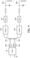
- Another useful feature of the proposed invention is that simply by including a demultiplexer at the output of the two read-ports the system can be easily reconfigured to do either multiline receive by reading out into two separate outputs, or apply the fundamental rejection filter by reading out into a single output with appropriately controlled delays.
- an embodiment includes ultrasound transducer probes and ultrasound systems that include delay lines having multiple outputs for multiline receive beamforming as well as for fundamental filtering.
- FIGURE 1 an ultrasound system constructed in accordance with the principles of the present invention is shown in block diagram form.
- a probe 10 has a transducer, such as a two dimensional array transducer 12.
- the elements of the array are coupled to a microbeamformer 14 located in the probe behind the transducer array.
- the microbeamformer applies timed transmit pulses to elements of the array to transmit beams in the desired directions and to the desired focal points in the three dimensional image field in front of the array.
- Echoes from the transmitted beams are received by the array elements and coupled to delays of the microbeamformer 14 where they are individually delayed.
- received signals from the array can be input into the microbeamformer and according to the architecture of the present invention with a non-destructive read of the stored charge, multiple outputs can be read at different delay times.
- one advantage of the present invention is its ability to do either multiline receive by reading out into two separate outputs, or apply the fundamental rejection filter by reading out into a single output with appropriately controlled delays.
- the probes and systems can be configured to perform multiline beamforming, the delayed signals of a group of transducer elements constituting a patch can be combined to form a partial sum signal for the patch.
- the elements of a patch in this embodiment are operated together and have their signals individually delayed in relation to a reference and then combined by the microbeamformer to form one signal from the patch to a probe conductor or an ultrasound system beamformer channel. Because multiple outputs from the delay line can be read at different times, different beams can be formed with a single delay line using different delays for each of the respective outputs.
- the probes and systems can be configured to perform the fundamental filtering, in which a single acoustic signal can be read out of the ARAM twice, separated by time, taking advantage of the fact that the ARAM allows for non-destructive read operations. The delayed signal and the original signal are summed, which results in a filtered signal.
- Combining of the different signals can be done by coupling the delayed signals to a common bus or summing node. Summing circuits or other circuitry can also be used.
- the signals can be coupled to a conductor of a cable 16 that is coupled to the system mainframe. In the system mainframe the signals are digitized and coupled to channels of a system beamformer 22. The signals are then combined to form a coherent steered and focused receive beam.
- the beam signals from the 3D image field are processed by a system image processor 24 to produce 2D or 3D images for display on an image display 30. Control of ultrasound system parameters such as probe selection, beam steering and focusing, and signal and image processing is done under control of a controller 26 which is coupled to various modules of the system. In the case of the probe 10 some of this control information is provided to the microbeamformer from the system mainframe over data lines of the cable 16. The user controls many of these operating parameters by means of a control panel 20.
- FIGURE 2 illustrates a detailed view of the delay elements of a microbeamformer for use in multiline beamforming.
- the channels 44 1 , 44 2 , 44 3 , ... 44 N of receive beamformer 40 which are coupled to the array 12, include programmable delay elements 46 1 , 46 2 , 46 3 , ... 46 N that have multiple outputs that correspond to different delayed reads of the stored charge in the delay element.
- two outputs are shown by way of example.
- the first output from each delay line is coupled to a first summing element 48 1
- the second output for each delay line is coupled to a second summing element 48 2 .
- the summing elements add the delayed signals from the respective outputs and provide the summed signals to the channel outputs 50 1 and 50 2 of receive beamformer 40.
- the summing elements include summing amplifiers or other analog adding circuits.
- each receive beamformer channel 44 N includes a variable gain amplifier (PREAMP), which controls gain as a function of received signal depth, and a delay element 46 N that delays acoustic data to achieve beam steering and dynamic focusing of the synthesized beam.
- the beamformer signal represents a receive ultrasound beam synthesized along a receive scan line.
- each analog delay line 46 N includes an analog RAM as is described in connection with FIGURE 3 .
- an analog random access memory (ARAM) device 60 can be configured as a programmable delay element.
- the analog RAM device 60 includes a group of M storage capacitive elements (including, e.g., capacitors) 62 1 , 62 2 ,. . . , 62 M for sampling the input signal using decoder 66 1 connected to input switches 65 1 , 65 2 , . . . , 65 M
- the analog RAM device 60 also includes a first and second read capability where the decoders 66 2 and 66 3 control first output switches 67 1 , 67 2 , ...
- An input buffer 64 receives a transducer signal that is then sent by input switch 65 N controlled by decoder 66 1 to storage capacitive element 62 N .
- the capacitive element of the present invention is configured for non-destructive reads such that when one read is processed the stored charge stays and can be read again at a different time.
- Decoder 66 2 coupled to output switches 67 M samples the individual capacitor charges at delay times determined by the difference in timing between an input counter 70 and a first output counter 72 1 .
- the ARAM 98 has two outputs (Out 1 & Out 2) 100a, 100b and two read control signal outputs (Read 1 & Read 2) 102a, 102b. These outputs are in communication with respective inputs of a pair of amplifiers 104a, 104b. These four output nodes are the two sides of the two different capacitors that are being accessed in the ARAM. Nominally Out 1 and Read 1 correspond to two sides of one capacitor that get switched across the output buffer as described in US Prov. Appl. 62/109,103 .
- the outputs from the amplifiers are fed to respective demultiplexers 106a, 106b which are coupled to ADCs in the system, wherein each associated pairing of amplifier and buffer together can be considered to form a respective buffer structure.
- demultiplexer 106a is coupled to 4 ADCs as shown in the dotted line expansion.
- a switch can be used to transmit the signal from amplifier 104a to any one of the four ADCs.
- four channels from the demultiplexer 106b can be coupled to the four ADCs such that amplifier 104b can send its signal to one of those ADCs.
- Other channels with demultiplexers can be coupled to the 4 ADCs as well.
- the other channels will also include their own respective amplifiers and be coupled to the outputs from the ARAM.
- the number of ADCs and outputs from the demultiplexer can be readily varied according to the necessary specifications required for the beamforming used in the ultrasound system.
- each demultiplexer 106a, 106b can include a gain selecting element, not shown.
- the gain selecting element includes a variable resistor (e.g., 110a, 110b).
- the variable resistor acting in conjunction with the input impedance of the ADC (or preamplifier) can be used to define the gain for each respective arm of the device.
- One use for this gain is to weight the filter as described in further detail below.
- FIGURE 5a shows a more detailed structural implementation of the ARAM 98.
- the illustrated embodiment of an ARAM device 160 includes a group of M storage capacitive elements (including, e.g., capacitors) 162 1 , 162 2 ,. . . , 162 M for sampling the input signal. Each capacitive storage element is in communication with a respective input switch 165 1 , 165 2 , . . . , 165 M
- the ARAM device also includes a respective set of first output switches 167 1 , 167 2 , . . . , 167 M and second output switches 168 1 , 168 2 , . . . , 168 M , to read the stored signal out with potentially different delays.
- An input buffer 164 receives a transducer signal that is then sent by input switch 165 N to storage capacitive element 162 N .
- each capacitive element is configured for non-destructive reads such that when one read is processed the stored charge stays and can be read again at a different time.
- the output switches 167 M sample the individual capacitor charges at selected delay times. Accordingly, the transducer signals are delayed by the selected delay times as they are transferred from input buffer 164 to a first output buffer 174 1 and a second output buffer 174 2 .
- FIGURE 5b illustrates the output of each of the two output buffers 174 1 , 174 2 as they are passed to summing element 189 in order to produce the filtered analog waveform.
- Each amplifier 104a, 104b receives the output of the ARAM 98 (i.e., the voltage that is stored on each capacitive element 162 M ).
- each amplifier includes an inverting amplifier driven by the respective output (Out 1, Out 2) to the voltage that was stored on the capacitive element that is being read. This read operation may be performed as described above.
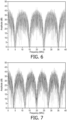
- the fundamental filtering can be carried out like a comb-filter resulting from the application of the differing delays for the primary signal and a summation which creates a notch near the fundamental frequency.
- the specific filter characteristics are adjustable. For example, by changing the delay, the filter may be tuned to operate on (notch out) a variety of different fundamental frequencies. The selection of filter notch frequency depends on the sampling rate and the amount of delay. As an example, for a 40Msps sample stream, a signal stream delayed by four samples summed with the initial stream results in a notch at 5MHz and a high-pass peak at 10MHz. In terms of finite impulse response (FIR) coefficients, this may be considered to be a [1 0 0 0 1] filter.
- FIR finite impulse response
- the fast Fourier transform (FFT) of a convolution of the filter coefficients with a random sample vector produces a frequency spectrum for this example of a delay and summation operation, which is shown in FIGURE 6 .
- FFT fast Fourier transform
Landscapes
- Engineering & Computer Science (AREA)
- Physics & Mathematics (AREA)
- Radar, Positioning & Navigation (AREA)
- Remote Sensing (AREA)
- Computer Networks & Wireless Communication (AREA)
- General Physics & Mathematics (AREA)
- Acoustics & Sound (AREA)
- Nonlinear Science (AREA)
- Ultra Sonic Daignosis Equipment (AREA)
- Investigating Or Analyzing Materials By The Use Of Ultrasonic Waves (AREA)
Applications Claiming Priority (2)
| Application Number | Priority Date | Filing Date | Title |
|---|---|---|---|
| US201562272732P | 2015-12-30 | 2015-12-30 | |
| PCT/EP2016/082788 WO2017114872A1 (en) | 2015-12-30 | 2016-12-28 | System and method for dynamic filtering |
Publications (2)
| Publication Number | Publication Date |
|---|---|
| EP3397987A1 EP3397987A1 (en) | 2018-11-07 |
| EP3397987B1 true EP3397987B1 (en) | 2023-12-20 |
Family
ID=57799693
Family Applications (1)
| Application Number | Title | Priority Date | Filing Date |
|---|---|---|---|
| EP16826357.2A Active EP3397987B1 (en) | 2015-12-30 | 2016-12-28 | System and method for dynamic filtering |
Country Status (5)
| Country | Link |
|---|---|
| US (2) | US11249188B2 (enExample) |
| EP (1) | EP3397987B1 (enExample) |
| JP (1) | JP6873141B2 (enExample) |
| CN (1) | CN108474844B (enExample) |
| WO (1) | WO2017114872A1 (enExample) |
Families Citing this family (6)
| Publication number | Priority date | Publication date | Assignee | Title |
|---|---|---|---|---|
| WO2017114872A1 (en) * | 2015-12-30 | 2017-07-06 | Koninklijke Philips N.V. | System and method for dynamic filtering |
| KR102605151B1 (ko) * | 2016-02-16 | 2023-11-23 | 삼성메디슨 주식회사 | 빔포밍을 수행하는 방법 및 빔포머. |
| GB2566437B (en) * | 2017-07-26 | 2022-12-07 | Sezanne Marine Ltd | Systems and methods for acoustic and/or electromagnetic imaging |
| KR20210122594A (ko) * | 2020-04-01 | 2021-10-12 | 삼성메디슨 주식회사 | 아날로그 빔포머, 그 제어 방법, 및 초음파 영상 장치 |
| CN120677651A (zh) * | 2022-12-13 | 2025-09-19 | Lg电子株式会社 | 无线媒体装置以及具有该无线媒体装置的图像显示装置 |
| US20240398386A1 (en) * | 2023-06-05 | 2024-12-05 | Canon Medical Systems Corporation | Ultrasound diagnosis apparatus and ultrasound signal generation method |
Family Cites Families (35)
| Publication number | Priority date | Publication date | Assignee | Title |
|---|---|---|---|---|
| JPH03173543A (ja) * | 1989-12-04 | 1991-07-26 | Hitachi Medical Corp | 超音波診断装置用受波整相回路 |
| US5345426A (en) | 1993-05-12 | 1994-09-06 | Hewlett-Packard Company | Delay interpolator for digital phased array ultrasound beamformers |
| US5469851A (en) | 1994-08-09 | 1995-11-28 | Hewlett-Packard Company | Time multiplexed digital ultrasound beamformer |
| US5997479A (en) * | 1998-05-28 | 1999-12-07 | Hewlett-Packard Company | Phased array acoustic systems with intra-group processors |
| JP2001340339A (ja) * | 2000-06-06 | 2001-12-11 | Hitachi Medical Corp | 超音波診断装置 |
| US6761691B2 (en) | 2000-07-21 | 2004-07-13 | Fuji Photo Film Co., Ltd. | Image forming method used in ultrasonic diagnosis, ultrasonic diagnostic apparatus, signal processing apparatus, and recording medium for recording signal processing program |
| US6468216B1 (en) * | 2000-08-24 | 2002-10-22 | Kininklijke Philips Electronics N.V. | Ultrasonic diagnostic imaging of the coronary arteries |
| US6695783B2 (en) | 2000-12-22 | 2004-02-24 | Koninklijke Philips Electronics N.V. | Multiline ultrasound beamformers |
| JP4723747B2 (ja) | 2001-04-09 | 2011-07-13 | 株式会社東芝 | 超音波診断装置 |
| US6500120B1 (en) * | 2001-07-31 | 2002-12-31 | Koninklijke Philips Electronics N.V. | Beamforming system using analog random access memory |
| US20030069504A1 (en) * | 2001-10-05 | 2003-04-10 | Siemens Medical Solutions Usa, Inc. | Receive filtering and filters for phase or amplitude coded pulse sequences |
| US6673016B1 (en) * | 2002-02-14 | 2004-01-06 | Siemens Medical Solutions Usa, Inc. | Ultrasound selectable frequency response system and method for multi-layer transducers |
| KR100490565B1 (ko) * | 2002-07-23 | 2005-05-19 | 주식회사 메디슨 | 아날로그 멀티플렉서를 이용한 디지털 수신 집속 장치 |
| US6827686B2 (en) | 2002-08-21 | 2004-12-07 | Koninklijke Philips Electronics N.V. | System and method for improved harmonic imaging |
| US20050131299A1 (en) * | 2003-12-10 | 2005-06-16 | Brent Robinson | Differential partial beamforming |
| JP2005285151A (ja) * | 2004-03-26 | 2005-10-13 | Seiko Epson Corp | 強誘電体メモリの素子構造、並びに非破壊読み出し方法 |
| CN101031816A (zh) | 2004-09-30 | 2007-09-05 | 皇家飞利浦电子股份有限公司 | 微波束形成换能器结构 |
| US7250885B1 (en) * | 2006-04-03 | 2007-07-31 | Analog Devices, Inc. | System and method for using timing skew estimation with a non-sequential time-interleaved analog-to-digital converter |
| CN101190136B (zh) | 2006-11-28 | 2012-07-18 | 深圳迈瑞生物医疗电子股份有限公司 | 实时产生滤波器系数的方法和装置 |
| CN101129268A (zh) * | 2007-10-09 | 2008-02-27 | 哈尔滨工业大学(威海) | 基波谐波复合成像方法及装置 |
| US8744155B2 (en) * | 2008-02-16 | 2014-06-03 | University Of Virginia Patent Foundation | Imaging or communications system utilizing multisample apodization and method |
| JP5572633B2 (ja) * | 2008-11-11 | 2014-08-13 | コーニンクレッカ フィリップス エヌ ヴェ | 超音波診断撮像システムのための設定可能なマイクロビームフォーマ回路 |
| WO2010067258A1 (en) * | 2008-12-10 | 2010-06-17 | Koninklijke Philips Electronics N.V. | Front-end circuit for an ultrasound transducer probe |
| EP2584971B1 (en) * | 2010-06-23 | 2021-11-10 | Analog Devices, Inc. | Ultrasound imaging with analog processing |
| JP2012139465A (ja) * | 2011-01-06 | 2012-07-26 | Konica Minolta Medical & Graphic Inc | 超音波診断装置 |
| US20120197130A1 (en) * | 2011-01-28 | 2012-08-02 | Shinichi Amemiya | Receiving circuit, ultrasonic probe, and ultrasonic image displaying apparatus |
| WO2014125371A1 (en) * | 2013-02-12 | 2014-08-21 | Urs-Us Medical Technology Inc. | Analog store digital read ultrasound beamforming system and method |
| US9274215B2 (en) * | 2013-03-08 | 2016-03-01 | Chison Medical Imaging, Inc. | Ultrasound fusion harmonic imaging systems and methods |
| JP6291814B2 (ja) * | 2013-11-29 | 2018-03-14 | セイコーエプソン株式会社 | 超音波トランスデューサーデバイス、超音波測定装置及び超音波画像装置 |
| US9736388B2 (en) * | 2013-12-13 | 2017-08-15 | Bio-Rad Laboratories, Inc. | Non-destructive read operations with dynamically growing images |
| EP3195004A1 (en) * | 2014-08-13 | 2017-07-26 | B-K Medical ApS | Ultrasound signal analog beamformer / beamforming |
| CN107110826B (zh) * | 2014-11-14 | 2020-05-19 | 阿萨斯医疗有限公司 | 基于模拟随机访问存储器阵列的超声波束形成系统和方法 |
| CN107209255B (zh) * | 2015-01-29 | 2022-03-01 | 皇家飞利浦有限公司 | 多线接收波束形成器以及相关的系统和方法 |
| US10656254B2 (en) * | 2015-11-19 | 2020-05-19 | Analog Devices, Inc. | Analog ultrasound beamformer |
| WO2017114872A1 (en) * | 2015-12-30 | 2017-07-06 | Koninklijke Philips N.V. | System and method for dynamic filtering |
-
2016
- 2016-12-28 WO PCT/EP2016/082788 patent/WO2017114872A1/en not_active Ceased
- 2016-12-28 CN CN201680077285.6A patent/CN108474844B/zh active Active
- 2016-12-28 EP EP16826357.2A patent/EP3397987B1/en active Active
- 2016-12-28 JP JP2018533936A patent/JP6873141B2/ja active Active
- 2016-12-28 US US16/065,851 patent/US11249188B2/en active Active
-
2022
- 2022-01-20 US US17/579,888 patent/US11846706B2/en active Active
Also Published As
| Publication number | Publication date |
|---|---|
| US11846706B2 (en) | 2023-12-19 |
| EP3397987A1 (en) | 2018-11-07 |
| CN108474844B (zh) | 2023-07-14 |
| JP6873141B2 (ja) | 2021-05-19 |
| CN108474844A (zh) | 2018-08-31 |
| WO2017114872A1 (en) | 2017-07-06 |
| US11249188B2 (en) | 2022-02-15 |
| JP2019500148A (ja) | 2019-01-10 |
| US20190094357A1 (en) | 2019-03-28 |
| US20220137211A1 (en) | 2022-05-05 |
Similar Documents
| Publication | Publication Date | Title |
|---|---|---|
| US11846706B2 (en) | System and method for dynamic filtering | |
| US5544128A (en) | Multi-beam digital beamforming method and apparatus | |
| US5388079A (en) | Partial beamforming | |
| US5891038A (en) | Method, apparatus and applications for combining transmit wave functions to obtain synthetic waveform in ultrasonic imaging system | |
| CN101495043B (zh) | 利用具有4x内插器的可调数字滤波器的超声波检测测量系统 | |
| US9717477B2 (en) | Ultrasonic diagnosis device and ultrasonic image acquisition method | |
| US11638573B2 (en) | Pulse offset ultrasonic imaging | |
| JP2007117755A (ja) | ドップラー受信ビーム生成器システムのための方法とシステム | |
| JP4039642B2 (ja) | 超音波ビーム形成装置 | |
| JP6192709B2 (ja) | 超音波レシーバフロントエンド | |
| WO2019206709A1 (en) | Ultrasound imaging system for high resolution wideband harmonic imaging | |
| US10451718B2 (en) | Ultrasound signal analog beamformer / beamforming | |
| CN111278363B (zh) | 超声成像设备、系统及其超声造影成像的图像增强方法 | |
| JP4690537B2 (ja) | 超音波診断装置 | |
| JP6838174B2 (ja) | 超音波プローブと処理方法 | |
| US6047601A (en) | Self-tuning crystal notch filter | |
| Mandersson et al. | Weighted least-squares pulse-shaping filters with application to ultrasonic signals | |
| Hassan et al. | 27 th National Radio Science Conference | |
| Busono et al. | Development of a Modular FPGA Based Digital Beamformer for PC Based Ultrasound Imaging System |
Legal Events
| Date | Code | Title | Description |
|---|---|---|---|
| STAA | Information on the status of an ep patent application or granted ep patent |
Free format text: STATUS: UNKNOWN |
|
| STAA | Information on the status of an ep patent application or granted ep patent |
Free format text: STATUS: THE INTERNATIONAL PUBLICATION HAS BEEN MADE |
|
| PUAI | Public reference made under article 153(3) epc to a published international application that has entered the european phase |
Free format text: ORIGINAL CODE: 0009012 |
|
| STAA | Information on the status of an ep patent application or granted ep patent |
Free format text: STATUS: REQUEST FOR EXAMINATION WAS MADE |
|
| 17P | Request for examination filed |
Effective date: 20180730 |
|
| AK | Designated contracting states |
Kind code of ref document: A1 Designated state(s): AL AT BE BG CH CY CZ DE DK EE ES FI FR GB GR HR HU IE IS IT LI LT LU LV MC MK MT NL NO PL PT RO RS SE SI SK SM TR |
|
| AX | Request for extension of the european patent |
Extension state: BA ME |
|
| DAV | Request for validation of the european patent (deleted) | ||
| DAX | Request for extension of the european patent (deleted) | ||
| RAP1 | Party data changed (applicant data changed or rights of an application transferred) |
Owner name: KONINKLIJKE PHILIPS N.V. |
|
| STAA | Information on the status of an ep patent application or granted ep patent |
Free format text: STATUS: EXAMINATION IS IN PROGRESS |
|
| 17Q | First examination report despatched |
Effective date: 20210514 |
|
| GRAP | Despatch of communication of intention to grant a patent |
Free format text: ORIGINAL CODE: EPIDOSNIGR1 |
|
| STAA | Information on the status of an ep patent application or granted ep patent |
Free format text: STATUS: GRANT OF PATENT IS INTENDED |
|
| INTG | Intention to grant announced |
Effective date: 20230726 |
|
| GRAS | Grant fee paid |
Free format text: ORIGINAL CODE: EPIDOSNIGR3 |
|
| GRAA | (expected) grant |
Free format text: ORIGINAL CODE: 0009210 |
|
| STAA | Information on the status of an ep patent application or granted ep patent |
Free format text: STATUS: THE PATENT HAS BEEN GRANTED |
|
| AK | Designated contracting states |
Kind code of ref document: B1 Designated state(s): AL AT BE BG CH CY CZ DE DK EE ES FI FR GB GR HR HU IE IS IT LI LT LU LV MC MK MT NL NO PL PT RO RS SE SI SK SM TR |
|
| REG | Reference to a national code |
Ref country code: GB Ref legal event code: FG4D |
|
| REG | Reference to a national code |
Ref country code: CH Ref legal event code: EP |
|
| REG | Reference to a national code |
Ref country code: DE Ref legal event code: R096 Ref document number: 602016084875 Country of ref document: DE |
|
| REG | Reference to a national code |
Ref country code: IE Ref legal event code: FG4D |
|
| REG | Reference to a national code |
Ref country code: DE Ref legal event code: R084 Ref document number: 602016084875 Country of ref document: DE |
|
| REG | Reference to a national code |
Ref country code: GB Ref legal event code: 746 Effective date: 20240220 |
|
| PG25 | Lapsed in a contracting state [announced via postgrant information from national office to epo] |
Ref country code: GR Free format text: LAPSE BECAUSE OF FAILURE TO SUBMIT A TRANSLATION OF THE DESCRIPTION OR TO PAY THE FEE WITHIN THE PRESCRIBED TIME-LIMIT Effective date: 20240321 |
|
| REG | Reference to a national code |
Ref country code: LT Ref legal event code: MG9D |
|
| PG25 | Lapsed in a contracting state [announced via postgrant information from national office to epo] |
Ref country code: LT Free format text: LAPSE BECAUSE OF FAILURE TO SUBMIT A TRANSLATION OF THE DESCRIPTION OR TO PAY THE FEE WITHIN THE PRESCRIBED TIME-LIMIT Effective date: 20231220 |
|
| REG | Reference to a national code |
Ref country code: NL Ref legal event code: MP Effective date: 20231220 |
|
| PG25 | Lapsed in a contracting state [announced via postgrant information from national office to epo] |
Ref country code: ES Free format text: LAPSE BECAUSE OF FAILURE TO SUBMIT A TRANSLATION OF THE DESCRIPTION OR TO PAY THE FEE WITHIN THE PRESCRIBED TIME-LIMIT Effective date: 20231220 |
|
| PG25 | Lapsed in a contracting state [announced via postgrant information from national office to epo] |
Ref country code: LT Free format text: LAPSE BECAUSE OF FAILURE TO SUBMIT A TRANSLATION OF THE DESCRIPTION OR TO PAY THE FEE WITHIN THE PRESCRIBED TIME-LIMIT Effective date: 20231220 Ref country code: GR Free format text: LAPSE BECAUSE OF FAILURE TO SUBMIT A TRANSLATION OF THE DESCRIPTION OR TO PAY THE FEE WITHIN THE PRESCRIBED TIME-LIMIT Effective date: 20240321 Ref country code: FI Free format text: LAPSE BECAUSE OF FAILURE TO SUBMIT A TRANSLATION OF THE DESCRIPTION OR TO PAY THE FEE WITHIN THE PRESCRIBED TIME-LIMIT Effective date: 20231220 Ref country code: ES Free format text: LAPSE BECAUSE OF FAILURE TO SUBMIT A TRANSLATION OF THE DESCRIPTION OR TO PAY THE FEE WITHIN THE PRESCRIBED TIME-LIMIT Effective date: 20231220 Ref country code: BG Free format text: LAPSE BECAUSE OF FAILURE TO SUBMIT A TRANSLATION OF THE DESCRIPTION OR TO PAY THE FEE WITHIN THE PRESCRIBED TIME-LIMIT Effective date: 20240320 |
|
| REG | Reference to a national code |
Ref country code: AT Ref legal event code: MK05 Ref document number: 1642918 Country of ref document: AT Kind code of ref document: T Effective date: 20231220 |
|
| PG25 | Lapsed in a contracting state [announced via postgrant information from national office to epo] |
Ref country code: NL Free format text: LAPSE BECAUSE OF FAILURE TO SUBMIT A TRANSLATION OF THE DESCRIPTION OR TO PAY THE FEE WITHIN THE PRESCRIBED TIME-LIMIT Effective date: 20231220 |
|
| PG25 | Lapsed in a contracting state [announced via postgrant information from national office to epo] |
Ref country code: SE Free format text: LAPSE BECAUSE OF FAILURE TO SUBMIT A TRANSLATION OF THE DESCRIPTION OR TO PAY THE FEE WITHIN THE PRESCRIBED TIME-LIMIT Effective date: 20231220 Ref country code: RS Free format text: LAPSE BECAUSE OF FAILURE TO SUBMIT A TRANSLATION OF THE DESCRIPTION OR TO PAY THE FEE WITHIN THE PRESCRIBED TIME-LIMIT Effective date: 20231220 Ref country code: NO Free format text: LAPSE BECAUSE OF FAILURE TO SUBMIT A TRANSLATION OF THE DESCRIPTION OR TO PAY THE FEE WITHIN THE PRESCRIBED TIME-LIMIT Effective date: 20240320 Ref country code: NL Free format text: LAPSE BECAUSE OF FAILURE TO SUBMIT A TRANSLATION OF THE DESCRIPTION OR TO PAY THE FEE WITHIN THE PRESCRIBED TIME-LIMIT Effective date: 20231220 Ref country code: LV Free format text: LAPSE BECAUSE OF FAILURE TO SUBMIT A TRANSLATION OF THE DESCRIPTION OR TO PAY THE FEE WITHIN THE PRESCRIBED TIME-LIMIT Effective date: 20231220 Ref country code: HR Free format text: LAPSE BECAUSE OF FAILURE TO SUBMIT A TRANSLATION OF THE DESCRIPTION OR TO PAY THE FEE WITHIN THE PRESCRIBED TIME-LIMIT Effective date: 20231220 |
|
| PG25 | Lapsed in a contracting state [announced via postgrant information from national office to epo] |
Ref country code: IS Free format text: LAPSE BECAUSE OF FAILURE TO SUBMIT A TRANSLATION OF THE DESCRIPTION OR TO PAY THE FEE WITHIN THE PRESCRIBED TIME-LIMIT Effective date: 20240420 |
|
| PG25 | Lapsed in a contracting state [announced via postgrant information from national office to epo] |
Ref country code: CZ Free format text: LAPSE BECAUSE OF FAILURE TO SUBMIT A TRANSLATION OF THE DESCRIPTION OR TO PAY THE FEE WITHIN THE PRESCRIBED TIME-LIMIT Effective date: 20231220 Ref country code: AT Free format text: LAPSE BECAUSE OF FAILURE TO SUBMIT A TRANSLATION OF THE DESCRIPTION OR TO PAY THE FEE WITHIN THE PRESCRIBED TIME-LIMIT Effective date: 20231220 |
|
| PG25 | Lapsed in a contracting state [announced via postgrant information from national office to epo] |
Ref country code: SK Free format text: LAPSE BECAUSE OF FAILURE TO SUBMIT A TRANSLATION OF THE DESCRIPTION OR TO PAY THE FEE WITHIN THE PRESCRIBED TIME-LIMIT Effective date: 20231220 |
|
| PG25 | Lapsed in a contracting state [announced via postgrant information from national office to epo] |
Ref country code: SM Free format text: LAPSE BECAUSE OF FAILURE TO SUBMIT A TRANSLATION OF THE DESCRIPTION OR TO PAY THE FEE WITHIN THE PRESCRIBED TIME-LIMIT Effective date: 20231220 Ref country code: SK Free format text: LAPSE BECAUSE OF FAILURE TO SUBMIT A TRANSLATION OF THE DESCRIPTION OR TO PAY THE FEE WITHIN THE PRESCRIBED TIME-LIMIT Effective date: 20231220 Ref country code: RO Free format text: LAPSE BECAUSE OF FAILURE TO SUBMIT A TRANSLATION OF THE DESCRIPTION OR TO PAY THE FEE WITHIN THE PRESCRIBED TIME-LIMIT Effective date: 20231220 Ref country code: IT Free format text: LAPSE BECAUSE OF FAILURE TO SUBMIT A TRANSLATION OF THE DESCRIPTION OR TO PAY THE FEE WITHIN THE PRESCRIBED TIME-LIMIT Effective date: 20231220 Ref country code: IS Free format text: LAPSE BECAUSE OF FAILURE TO SUBMIT A TRANSLATION OF THE DESCRIPTION OR TO PAY THE FEE WITHIN THE PRESCRIBED TIME-LIMIT Effective date: 20240420 Ref country code: EE Free format text: LAPSE BECAUSE OF FAILURE TO SUBMIT A TRANSLATION OF THE DESCRIPTION OR TO PAY THE FEE WITHIN THE PRESCRIBED TIME-LIMIT Effective date: 20231220 Ref country code: CZ Free format text: LAPSE BECAUSE OF FAILURE TO SUBMIT A TRANSLATION OF THE DESCRIPTION OR TO PAY THE FEE WITHIN THE PRESCRIBED TIME-LIMIT Effective date: 20231220 Ref country code: AT Free format text: LAPSE BECAUSE OF FAILURE TO SUBMIT A TRANSLATION OF THE DESCRIPTION OR TO PAY THE FEE WITHIN THE PRESCRIBED TIME-LIMIT Effective date: 20231220 |
|
| REG | Reference to a national code |
Ref country code: CH Ref legal event code: PL |
|
| PG25 | Lapsed in a contracting state [announced via postgrant information from national office to epo] |
Ref country code: PL Free format text: LAPSE BECAUSE OF FAILURE TO SUBMIT A TRANSLATION OF THE DESCRIPTION OR TO PAY THE FEE WITHIN THE PRESCRIBED TIME-LIMIT Effective date: 20231220 Ref country code: PT Free format text: LAPSE BECAUSE OF FAILURE TO SUBMIT A TRANSLATION OF THE DESCRIPTION OR TO PAY THE FEE WITHIN THE PRESCRIBED TIME-LIMIT Effective date: 20240422 |
|
| PG25 | Lapsed in a contracting state [announced via postgrant information from national office to epo] |
Ref country code: LU Free format text: LAPSE BECAUSE OF NON-PAYMENT OF DUE FEES Effective date: 20231228 |
|
| REG | Reference to a national code |
Ref country code: BE Ref legal event code: MM Effective date: 20231231 |
|
| PG25 | Lapsed in a contracting state [announced via postgrant information from national office to epo] |
Ref country code: PT Free format text: LAPSE BECAUSE OF FAILURE TO SUBMIT A TRANSLATION OF THE DESCRIPTION OR TO PAY THE FEE WITHIN THE PRESCRIBED TIME-LIMIT Effective date: 20240422 Ref country code: PL Free format text: LAPSE BECAUSE OF FAILURE TO SUBMIT A TRANSLATION OF THE DESCRIPTION OR TO PAY THE FEE WITHIN THE PRESCRIBED TIME-LIMIT Effective date: 20231220 Ref country code: LU Free format text: LAPSE BECAUSE OF NON-PAYMENT OF DUE FEES Effective date: 20231228 |
|
| REG | Reference to a national code |
Ref country code: DE Ref legal event code: R097 Ref document number: 602016084875 Country of ref document: DE |
|
| PG25 | Lapsed in a contracting state [announced via postgrant information from national office to epo] |
Ref country code: MC Free format text: LAPSE BECAUSE OF FAILURE TO SUBMIT A TRANSLATION OF THE DESCRIPTION OR TO PAY THE FEE WITHIN THE PRESCRIBED TIME-LIMIT Effective date: 20231220 |
|
| REG | Reference to a national code |
Ref country code: IE Ref legal event code: MM4A |
|
| PG25 | Lapsed in a contracting state [announced via postgrant information from national office to epo] |
Ref country code: IE Free format text: LAPSE BECAUSE OF NON-PAYMENT OF DUE FEES Effective date: 20231228 |
|
| PG25 | Lapsed in a contracting state [announced via postgrant information from national office to epo] |
Ref country code: DK Free format text: LAPSE BECAUSE OF FAILURE TO SUBMIT A TRANSLATION OF THE DESCRIPTION OR TO PAY THE FEE WITHIN THE PRESCRIBED TIME-LIMIT Effective date: 20231220 |
|
| PG25 | Lapsed in a contracting state [announced via postgrant information from national office to epo] |
Ref country code: BE Free format text: LAPSE BECAUSE OF NON-PAYMENT OF DUE FEES Effective date: 20231231 |
|
| PG25 | Lapsed in a contracting state [announced via postgrant information from national office to epo] |
Ref country code: CH Free format text: LAPSE BECAUSE OF NON-PAYMENT OF DUE FEES Effective date: 20231231 |
|
| PLBE | No opposition filed within time limit |
Free format text: ORIGINAL CODE: 0009261 |
|
| STAA | Information on the status of an ep patent application or granted ep patent |
Free format text: STATUS: NO OPPOSITION FILED WITHIN TIME LIMIT |
|
| PG25 | Lapsed in a contracting state [announced via postgrant information from national office to epo] |
Ref country code: SI Free format text: LAPSE BECAUSE OF FAILURE TO SUBMIT A TRANSLATION OF THE DESCRIPTION OR TO PAY THE FEE WITHIN THE PRESCRIBED TIME-LIMIT Effective date: 20231220 |
|
| PG25 | Lapsed in a contracting state [announced via postgrant information from national office to epo] |
Ref country code: SI Free format text: LAPSE BECAUSE OF FAILURE TO SUBMIT A TRANSLATION OF THE DESCRIPTION OR TO PAY THE FEE WITHIN THE PRESCRIBED TIME-LIMIT Effective date: 20231220 Ref country code: IE Free format text: LAPSE BECAUSE OF NON-PAYMENT OF DUE FEES Effective date: 20231228 Ref country code: DK Free format text: LAPSE BECAUSE OF FAILURE TO SUBMIT A TRANSLATION OF THE DESCRIPTION OR TO PAY THE FEE WITHIN THE PRESCRIBED TIME-LIMIT Effective date: 20231220 Ref country code: CH Free format text: LAPSE BECAUSE OF NON-PAYMENT OF DUE FEES Effective date: 20231231 Ref country code: BE Free format text: LAPSE BECAUSE OF NON-PAYMENT OF DUE FEES Effective date: 20231231 |
|
| 26N | No opposition filed |
Effective date: 20240923 |
|
| PG25 | Lapsed in a contracting state [announced via postgrant information from national office to epo] |
Ref country code: FR Free format text: LAPSE BECAUSE OF NON-PAYMENT OF DUE FEES Effective date: 20240220 |
|
| PG25 | Lapsed in a contracting state [announced via postgrant information from national office to epo] |
Ref country code: FR Free format text: LAPSE BECAUSE OF NON-PAYMENT OF DUE FEES Effective date: 20240220 |
|
| PG25 | Lapsed in a contracting state [announced via postgrant information from national office to epo] |
Ref country code: CY Free format text: LAPSE BECAUSE OF FAILURE TO SUBMIT A TRANSLATION OF THE DESCRIPTION OR TO PAY THE FEE WITHIN THE PRESCRIBED TIME-LIMIT; INVALID AB INITIO Effective date: 20161228 |
|
| PG25 | Lapsed in a contracting state [announced via postgrant information from national office to epo] |
Ref country code: HU Free format text: LAPSE BECAUSE OF FAILURE TO SUBMIT A TRANSLATION OF THE DESCRIPTION OR TO PAY THE FEE WITHIN THE PRESCRIBED TIME-LIMIT; INVALID AB INITIO Effective date: 20161228 |
|
| PG25 | Lapsed in a contracting state [announced via postgrant information from national office to epo] |
Ref country code: TR Free format text: LAPSE BECAUSE OF FAILURE TO SUBMIT A TRANSLATION OF THE DESCRIPTION OR TO PAY THE FEE WITHIN THE PRESCRIBED TIME-LIMIT Effective date: 20231220 |
|
| PGFP | Annual fee paid to national office [announced via postgrant information from national office to epo] |
Ref country code: GB Payment date: 20251223 Year of fee payment: 10 |
|
| PGFP | Annual fee paid to national office [announced via postgrant information from national office to epo] |
Ref country code: DE Payment date: 20251229 Year of fee payment: 10 |