EP3397923B1 - Verbesserter vermessungsstab - Google Patents
Verbesserter vermessungsstab Download PDFInfo
- Publication number
- EP3397923B1 EP3397923B1 EP15823178.7A EP15823178A EP3397923B1 EP 3397923 B1 EP3397923 B1 EP 3397923B1 EP 15823178 A EP15823178 A EP 15823178A EP 3397923 B1 EP3397923 B1 EP 3397923B1
- Authority
- EP
- European Patent Office
- Prior art keywords
- pole
- ground point
- top end
- data
- determined
- Prior art date
- Legal status (The legal status is an assumption and is not a legal conclusion. Google has not performed a legal analysis and makes no representation as to the accuracy of the status listed.)
- Active
Links
- 238000000034 method Methods 0.000 claims description 39
- 238000012545 processing Methods 0.000 claims description 23
- 230000001133 acceleration Effects 0.000 claims description 16
- 230000006870 function Effects 0.000 claims description 13
- 238000004891 communication Methods 0.000 claims description 7
- 238000012937 correction Methods 0.000 claims description 6
- 230000007246 mechanism Effects 0.000 claims description 5
- 230000005055 memory storage Effects 0.000 claims description 5
- 238000004590 computer program Methods 0.000 claims description 4
- 238000004422 calculation algorithm Methods 0.000 description 11
- 230000008569 process Effects 0.000 description 9
- 238000005259 measurement Methods 0.000 description 7
- 239000011159 matrix material Substances 0.000 description 6
- 206010000210 abortion Diseases 0.000 description 5
- 230000009897 systematic effect Effects 0.000 description 5
- 230000005672 electromagnetic field Effects 0.000 description 4
- 238000005070 sampling Methods 0.000 description 4
- 208000032365 Electromagnetic interference Diseases 0.000 description 3
- 230000008901 benefit Effects 0.000 description 3
- 230000007613 environmental effect Effects 0.000 description 3
- 230000005484 gravity Effects 0.000 description 3
- 238000012805 post-processing Methods 0.000 description 3
- 238000004364 calculation method Methods 0.000 description 2
- 230000008859 change Effects 0.000 description 2
- 238000010276 construction Methods 0.000 description 2
- 230000003068 static effect Effects 0.000 description 2
- 238000013519 translation Methods 0.000 description 2
- 230000004075 alteration Effects 0.000 description 1
- 238000003491 array Methods 0.000 description 1
- POJOORKDYOPQLS-UHFFFAOYSA-L barium(2+) 5-chloro-2-[(2-hydroxynaphthalen-1-yl)diazenyl]-4-methylbenzenesulfonate Chemical compound [Ba+2].C1=C(Cl)C(C)=CC(N=NC=2C3=CC=CC=C3C=CC=2O)=C1S([O-])(=O)=O.C1=C(Cl)C(C)=CC(N=NC=2C3=CC=CC=C3C=CC=2O)=C1S([O-])(=O)=O POJOORKDYOPQLS-UHFFFAOYSA-L 0.000 description 1
- 238000013461 design Methods 0.000 description 1
- 230000000694 effects Effects 0.000 description 1
- 230000005674 electromagnetic induction Effects 0.000 description 1
- 238000013507 mapping Methods 0.000 description 1
- 238000012986 modification Methods 0.000 description 1
- 230000004048 modification Effects 0.000 description 1
- 230000003287 optical effect Effects 0.000 description 1
- 230000000737 periodic effect Effects 0.000 description 1
- 230000002277 temperature effect Effects 0.000 description 1
Images


Classifications
-
- G—PHYSICS
- G01—MEASURING; TESTING
- G01C—MEASURING DISTANCES, LEVELS OR BEARINGS; SURVEYING; NAVIGATION; GYROSCOPIC INSTRUMENTS; PHOTOGRAMMETRY OR VIDEOGRAMMETRY
- G01C1/00—Measuring angles
- G01C1/02—Theodolites
-
- G—PHYSICS
- G01—MEASURING; TESTING
- G01C—MEASURING DISTANCES, LEVELS OR BEARINGS; SURVEYING; NAVIGATION; GYROSCOPIC INSTRUMENTS; PHOTOGRAMMETRY OR VIDEOGRAMMETRY
- G01C15/00—Surveying instruments or accessories not provided for in groups G01C1/00 - G01C13/00
- G01C15/02—Means for marking measuring points
- G01C15/06—Surveyors' staffs; Movable markers
-
- G—PHYSICS
- G01—MEASURING; TESTING
- G01C—MEASURING DISTANCES, LEVELS OR BEARINGS; SURVEYING; NAVIGATION; GYROSCOPIC INSTRUMENTS; PHOTOGRAMMETRY OR VIDEOGRAMMETRY
- G01C15/00—Surveying instruments or accessories not provided for in groups G01C1/00 - G01C13/00
- G01C15/12—Instruments for setting out fixed angles, e.g. right angles
-
- G—PHYSICS
- G01—MEASURING; TESTING
- G01C—MEASURING DISTANCES, LEVELS OR BEARINGS; SURVEYING; NAVIGATION; GYROSCOPIC INSTRUMENTS; PHOTOGRAMMETRY OR VIDEOGRAMMETRY
- G01C21/00—Navigation; Navigational instruments not provided for in groups G01C1/00 - G01C19/00
- G01C21/10—Navigation; Navigational instruments not provided for in groups G01C1/00 - G01C19/00 by using measurements of speed or acceleration
- G01C21/12—Navigation; Navigational instruments not provided for in groups G01C1/00 - G01C19/00 by using measurements of speed or acceleration executed aboard the object being navigated; Dead reckoning
- G01C21/16—Navigation; Navigational instruments not provided for in groups G01C1/00 - G01C19/00 by using measurements of speed or acceleration executed aboard the object being navigated; Dead reckoning by integrating acceleration or speed, i.e. inertial navigation
- G01C21/165—Navigation; Navigational instruments not provided for in groups G01C1/00 - G01C19/00 by using measurements of speed or acceleration executed aboard the object being navigated; Dead reckoning by integrating acceleration or speed, i.e. inertial navigation combined with non-inertial navigation instruments
-
- G—PHYSICS
- G01—MEASURING; TESTING
- G01S—RADIO DIRECTION-FINDING; RADIO NAVIGATION; DETERMINING DISTANCE OR VELOCITY BY USE OF RADIO WAVES; LOCATING OR PRESENCE-DETECTING BY USE OF THE REFLECTION OR RERADIATION OF RADIO WAVES; ANALOGOUS ARRANGEMENTS USING OTHER WAVES
- G01S19/00—Satellite radio beacon positioning systems; Determining position, velocity or attitude using signals transmitted by such systems
- G01S19/38—Determining a navigation solution using signals transmitted by a satellite radio beacon positioning system
- G01S19/39—Determining a navigation solution using signals transmitted by a satellite radio beacon positioning system the satellite radio beacon positioning system transmitting time-stamped messages, e.g. GPS [Global Positioning System], GLONASS [Global Orbiting Navigation Satellite System] or GALILEO
- G01S19/42—Determining position
- G01S19/51—Relative positioning
Definitions
- the present invention relates generally to the field of topographic surveying poles, and in particular, to a method and device for improved position determination by a surveying pole, in particular, a surveying pole with improved robustness and extended availability.
- FIG. 1 depicts a GNSS-based pole 100 which comprises a rod 110 with a bottom end 120 for positioning on a point 140 on the ground which needs to be localized.
- the top end 130 comprises a GNSS device for determining the geographical coordinates of the GNSS antenna reference point 150.
- GNSS-based poles are easier to operate because they do not need external equipment for making further measurements as all GNSS electronics are contained within the GNSS device. They also provide fast position computation and, thus a faster topographic survey, than traditional mirror-based systems. Publications US-A-2009/0024325 , EP-A-2722647 , and US-B-5929807 disclose three such example GNSS-based surveying poles.
- the theoretical basis underlying the surveying pole is to first compute the GNSS antenna position 150 through a geodetic GNSS receiver and subsequently project the point to the ground taking into account the height difference 160.
- the operation is performed by a user that handles the surveying pole, placing the bottom end 120 on a desired ground point 140 for obtaining its 3D position coordinates.
- the main drawback is that the pole needs to be completely vertical, therefore it is necessary to level the pole using a level. This requires further handling, takes more time, and can lead to errors.
- FIG. 2 depicts such situations, wherein a tree 220 or building 230 obstructs (represented by the cross) the direct line-of-sight between the GNSS device and the satellite system 210.
- the capability of tilting the pole has the advantage of measuring points that were otherwise inaccessible, like in environmental conditions where a full visibility of the sky is not possible, such as areas obstructed by trees, inside buildings or other obstacle objects.
- by tilting the pole it is possible to have a direct line of sight to more satellites than otherwise, and hence a more precise ground point position can be determined.
- the attitude, or orientation, of the tilted pole needs to be determined in order to determine the actual vertical difference between the top and bottom ends of the pole.
- additional hardware sensors to measure this pole orientation and compensate for the vertical height difference due to the pole being tilted.
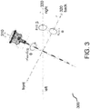
- FIG. 3 depicts the three rotation angles defining the attitude, or orientation, of a surveying pole.
- the first angle ⁇ the heading or yaw
- the second angle ⁇ the pitch
- the third angle ⁇ the roll
- the third angle ⁇ is the angle which defines a rotation around the horizontal x-axis 330. When the pole is completely vertical, the roll is zero, however by moving the pole right or left, a roll is generated.
- FIG. 4 depicts a surveying pole 400 comprising the additional magnetometer and inclinometer components within the GNSS device 410.
- the magnetometer it is possible to obtain the pole orientation in relation to the magnetic North, that is, the heading.
- the remaining two tilt angles (pitch and roll) of the pole it is possible to determine the remaining two tilt angles (pitch and roll) of the pole in relation to the vertical axis respect to ground.
- this solution allows working in tilted mode as all three angles are obtained using a magnetometer and inclinometer.
- a positioning pole comprising a satellite positioning sensor and an inertial sensor.
- An initialization phase determines the ground point position and absolute heading with respect to the geographic North with high accuracy using inertial data samples corresponding to at least three different pole inclinations.
- the absolute heading is then used in an operational phase enabling using the pole for new ground point or orientation determinations, however without having to perform a new initialization procedure every time.
- the improved positioning pole When in open spaces, that is, "unmagnetized” scenarios, the improved positioning pole is capable of locating ground points with extremely high accuracy and at least the same accuracy as current topographic systems.
- the improved pole In half-occluded spaces or spaces with strong electromagnetic fields, where classical GNSS based poles are not capable of operating, the improved pole enables performing speedy positioning with topographic acceptable performance, however without the use of magnetic sensors.
- a surveying pole is provided which is more robust (because it is not affected by magnetic fields) and has extended availability (because it can measure where other poles cannot, for example, environments with no or low line-of-sight satellite visibility).
- the invention provides methods and devices that implement various aspects, embodiments, and features of the invention, and are implemented by various means.
- the various means may comprise, for example, hardware, software, firmware, or a combination thereof, and these techniques may be implemented in any single one, or combination of, the various means.
- the various means may comprise processing units implemented within one or more application specific integrated circuits (ASICs), digital signal processors (DSPs), digital signal processing devices (DSPDs), programmable logic devices (PLDs), field programmable gate arrays (FPGAs), processors, controllers, micro-controllers, microprocessors, other electronic units designed to perform the functions described herein, or a combination thereof.
- ASICs application specific integrated circuits
- DSPs digital signal processors
- DSPDs digital signal processing devices
- PLDs programmable logic devices
- FPGAs field programmable gate arrays
- processors controllers, micro-controllers, microprocessors, other electronic units designed to perform the functions described herein, or a combination thereof.
- the various means may comprise modules (for example, procedures, functions, and so on) that perform the functions described herein.
- the software codes may be stored in a memory unit and executed by a processor.
- the memory unit may be implemented within the processor or external to the processor.
- FIG. 5 depicts an improved positioning pole 500 according to one embodiment of the invention.
- the pole comprises a rod 510 with a bottom end 520 for positioning on a point 140 on the ground which needs to be localized.
- the top end 530 comprises a positioning device for determining the orientation angles of the pole and the geodetic coordinates of a reference point 550.
- the inventors take advantage of the constant length 560 of the rod, the fact that the bottom end 520 is placed on the same ground point 140 during the entire process, and considering the coordinates of the top end 550 are determined by satellite positioning and the relative orientation of the pole by the inertial sensors.
- the pole comprises hardware components which operate according to an algorithm, or software, for performing improved position determination.
- the process is performed iteratively by a Kalman filter, which is initialized by a first information set which is then continually updated periodically sequentially in time.
- the Kalman filter of the positioning device recalculates the orientation angles (from angular velocities) and positions (from linear accelerations).
- FIG. 6 depicts the means for position determination 600, or positioning device, comprising means for satellite positioning 610, 620, means for inertial sensing 630, processing means 640 and memory means 670.
- the result of the position determination can be output to external devices 680.
- the means for satellite positioning comprises a GNSS antenna 610 connected to a GNSS receiver 620 for communicating with one or more satellites according to the GNSS protocol and receiving raw satellite position data.
- the raw satellite data is used to determine the GNSS coordinates of the top end by using differential processing. This can be achieved by either using 1) a GNSS receiver including differential processing capabilities, 2) applying real time kinetic corrections in real-time from an RTK processor, or 3) apply such differential processing off-line, in a post-processing stage. Both are connected by a radio frequency RF cable (low attenuation on signals below 2 GHz) and the satellite positioning means is connected to the processing means 640 by a digital serial communication (RS232 or similar).
- RS232 digital serial communication
- the inertial sensing means 630 is an inertial measurement unit IMU comprising accelerometers and angular rate sensors, or gyroscopes. It is connected to the processing means 640 via a communication interface, such as a serial-to-parallel interface SPI (or analogous communication channel, analogic or digital).
- a communication interface such as a serial-to-parallel interface SPI (or analogous communication channel, analogic or digital).
- SPI serial-to-parallel interface
- the skilled person can use readily available IMU's as long as they provide the inertial data necessary for subsequently determining the orientation of the positioning pole.
- the processing means 640 comprises an acquisition means 650, or acquisition module, and data processing means 660, or data processing module.
- the acquisition means comprises initialization means 652 for initial ground point position and orientation estimation. The ground point is determined based on the inertial data using mechanization equations.
- the processing means further comprises timing means 654 for time-tagging the position data as well as the inertial data. The output of the timing means is sent to the communication means 656 for delivering the data to the data processing means 660 via a communication interface, such as the TCP/IP protocol, or similar.
- a copy of the data is stored locally in memory storage 658 as well as, optionally, in memory means 670, for external post-processing.
- Internal memory means 670 may be permanently installed or be removably coupled to the processing means 640 and can be, for example, a smart disk SD card.
- the timing means 654 provides the reference timing for time tagging the raw data acquired.
- this reference clock is quite unstable and therefore needs to be stabilized.
- the correction is made using the pulse-per-second PPS synchronization signal provided by the GNSS receiver 620.
- the processor clock drift is compensated for using this PPS signal at one second intervals in order to maintain a good reference time-stamp, resulting in an accurate time tagging.
- the data processing means 660 is responsible for determining the ground point position 140 using the data determined from the acquisition means as input to the Kalman filter. This ground point computation is performed by the means for positioning 662 and, optionally, transmitted by communication means 664 to any external device 680, such as human interface or display, via the TCP/IP protocol, or similar. A copy of the computed ground points is stored locally in memory storage 666 as well as, optionally, in memory means 670.
- the position of the ground is determined starting from an initial ground point estimation which is a rough ground point position determined based on the coordinates of the GNSS antenna point 550 and the knowledge of the pole length 510.
- the initial ground point estimation is determined by solving the following least squares problem wherein the antenna point coordinates and the ground point coordinates are related through the pole length.
- the ground point is accurately determined by obtaining at least two other ground point estimations at two different pole orientations, or attitudes. This is done by tilting the pole in different directions and estimating the ground point.
- the final ground point is based on the result of at least three data sets.
- the at least three data sets provide orientation angle information from the inertial sensor used to determine with certainty the position of the ground point.
- An inertial sensor or inertial measurement unit IMU, is an electronic device that measures and reports specific forces and angular rates exerted on a body, using a combination of three accelerometers and three gyroscopes.
- An accelerometer measures acceleration forces based on Newton's second law "The acceleration of a body is parallel and directly proportional to the net applied force F and inversely proportional to its mass m". Typically, acceleration units are expressed in meters per second per second (m/s 2 ).
- a gyroscope measures angular rotation increments from a reference orientation. Gyroscopes are based on the Coriolis effect, measuring the deflection force (Fc) of moving objects when they are rotating through a reference frame.
- gyroscope units are expressed in degrees per second (deg/sec).
- the accelerometers and gyroscopes are placed in such a way that their measuring axes are orthogonal to each other, being three different axis (x,y,z).
- the inertial sensor generates inertial data comprising three accelerations (one for each axis) and three gyroscopes (one for each axis).
- Inertial data samples are obtained for at least three pole inclinations. From the inertial data at any one inclination, the pitch and roll of the surveying pole may be determined.
- the pitch angle is determined as the arc sinus of the measured acceleration in the x-axis of the body-frame divided by the constant Earth's gravitational.
- the roll angle is determined as the arc sinus of the measured acceleration in the y-axis of the body-frame divided by the constant Earth's gravitational.
- ⁇ is the pitch angle
- ⁇ is the roll angle
- a x is the medium acceleration measured in the x-axis
- a y is the medium acceleration measured in the y-axis
- g is the gravity force equal to 9.81 m/s 2 .
- the pitch and the roll orientation angles are determined based on medium acceleration data of the x-axis and the y-axis, respectively.
- the final ground point position corresponds to the candidate which is common to, at least three, different pole inclinations, or attitudes. In other words, it is the candidate which coincides with all pole inclinations.
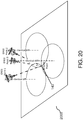
- FIG. 20 depicts the pole at three different inclinations, or attitudes (GNSS points 1 to 3). The point at which the candidate ground point is the same for all three inclinations is the final ground point 140. In the depiction of FIG. 20 , this corresponds with the point of intersection of the three circles, each circle corresponding to the plurality of candidates possible at each pole attitude. Hence, a minimum of three ground point candidates are necessary in order to determine the final ground point value with certainty.
- a position determining device is provided on a surveying pole which functions accurately even in magnetized environments as it does not make us of magnetometers.
- a position determining device is provided on a surveying pole which functions accurately even in magnetized environments as it does not make us of magnetometers.
- the new ground point position can be derived based on the previous and the new heading information.
- the pitch and roll may be determined directly from the inertial data, the absolute heading cannot be determined directly, as only relative information is available.
- the heading, or absolute North is determined, using the data from the at least three samples as well as the determined ground point.
- a simple user-friendly algorithm permits, in a first initialization phase, any specialized or non-specialized user to initialize the device when in line-of-sight contact with GNSS satellites.
- the user may continue using the surveying pole in environments without line-of-sight contact with satellites, as the internal tracking mechanism permits computing the pitch, roll and heading as well as the geodesic coordinates of the pole at all times.
- a user-friendly positioning pole is provided which accurately operates in a simple, economic and resource efficient manner even in scenarios with electromagnetic interferences and which do not provide direct contact to satellites.
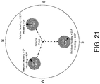
- FIG. 21 depicts the process of determining the absolute heading using the data sets of three sampling points, or attitudes.
- the absolute heading angle ⁇ or the angle with respect to the geographic north, is determined based on pitch, roll, vertical projection, and horizontal projection determined from the at least three initial data samples.
- the heading ⁇ is determined by projecting each GNSS point to the known ground point at each of at least three attitude angles by using a rotation matrix (containing the heading, pitch and roll angles) and using a translation vector (the pole distance):
- Xg Xi + RM ⁇ , ⁇ , ⁇ * Tv 0,0 L
- L is the (known) pole length 560
- ⁇ is the (known) pitch angle
- ⁇ is the (known) roll angle
- ⁇ is the (unknown) heading angle
- Xi are the (known) GNSS antenna geodetic coordinates 550 of ith-step
- Xg is the (known) geodetic coordinates of the ground point 140 which has to be determined
- RM is the rotation matrix
- Tv is the translation vector.
- the process of determining the position and orientation by the surveying pole is completed as the positioning device provides, by a display or some other interface, the coordinates of the ground point, as well as the orientation of the pole, comprising the heading, pitch, and roll angles.
- the position and orientation determination process is performed however using more than three candidates.
- the error tolerance in the ground point candidates is reduced and the inherent sensor inaccuracies are filtered out.
- higher accuracy is obtained at the cost of speed, as more measurements are necessary.
- further details are provided, however using the determination of five samples, as an example. The skilled person will understand that the same description can be applied to any number of samples as long as they are data sets obtained from at least three different attitudes.
- the inertial sensors exhibit inherent inaccuracies, which propagate and result in further errors in angle determination. Errors can be classified as systematic errors such as bias (for example due to misalignments and temperature effects) and non-systematic errors, such as due to environmental white noise.
- the inertial sensing means comprises an error compensation mechanism to correct systematic errors, or bias.
- the bias of inertial sensing means results in inaccuracies in angle determination which end up representing ground point candidates which are also not accurate and suffer from deviations. Moreover, this complicates the accurate determination of the final ground point which is the one candidate which should be the same at the at least three different attitudes, since no candidates completely coincide.
- the positioning means is calibrated by estimating the bias of the inertial sensor, and iteratively subtracting it from the inertial data readings, resulting in compensated inertial data.
- the compensated inertial data free from inherent systematic errors, result in a high degree of accuracy in ground point position and orientation determination.
- B accel is the (unknown) vector representing the bias of the accelerometer in the body frame.
- the vector a b is the (known) mean values of sensed accelerations from the inertial sensor (in a Bfrd configuration) in the first calibration step
- R M is the (known) rotation matrix between the local reference frame and the body reference frame
- g is the gravity force equal to 9.81 m/s 2 .
- the accelerometer sensor bias values are determined, in a static position, based on the unique force measured being the gravity force. The force can be distributed in the three axes so a rotation matrix is needed to transform the local reference frame to the body reference frame.
- B gyro is the (unknown) vector representing the bias of the gyroscopes in the body frame.
- the vector w b is the (known) mean values of sensed angular velocities from the inertial sensor (in a Bfrd configuration) in the first calibration step
- R b e is the (known) rotation matrix between the Earth Centered Earth Fixed, ECEF, reference frame and the body reference frame
- w is the velocity rotation of the earth equal to 15o/h.
- the gyroscope sensor bias values are determined, in a static position, by knowing that the unique angular rotation measured is the rotation of the earth.
- the angular velocity can be distributed in the three axes so a rotation matrix is needed to transform the Earth Centered Earth Fixed, ECEF, reference frame to the body reference frame.
- the (unknown) vector of corrected accelerations (a b c ) is the subtraction of the previously calculated (known) vector of accelerometer biases (B b accel ) from the actual (known) vector of measured accelerations in body frame (a b ).
- the (unknown) vector of corrected angular velocities (w b ) is the subtraction of the previously calculated (known) vector of angular velocities biases (B b gyro ) from the actual (known) vector of measured angular velocities in body frame (w b ).
- w b c w b ⁇ B b gyro
- w b is the vector of measured angular velocities in body frame
- B b gyro the vector of angular velocities biases
- w b c is the vector of corrected angular velocities.
- the ground position and orientation angles ⁇ , ⁇ , ⁇ of the pole are more accurately determined.
- the description comprises the error correction, however, as mentioned, the pole orientation and position determination may also be used without error correction mechanism described, however it will not be as accurate.
- FIG. 7 depicts a method 700 for determining the initial values of the ground coordinates comprising the error-correction mechanism.
- the attitude, or three dimensional pole orientations is determined 710.
- the inertial sensor calibration values are determined 720.
- the ground point coordinates are determined 730 based on the determined attitude and calibration values.
- the attitude determination algorithm 710 comprises determining the orientation parameters of the positioning pole 500, that is, determining the heading angle ⁇ , the pitch angle ⁇ and the roll angle ⁇ .
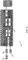
- FIG. 8 depicts visually the pole movement (top view of the pole) in the aspect comprising sampling five data sets, where a first GNSS position is determined at a first position 810, then a second GNSS position is determined at a second position 820, then a third GNSS position is determined at a third position 830, then a fourth GNSS position is determined at a fourth position 840, and a fifth GNSS position is determined at a fifth position 850.
- the user is prompted to change positions by an indicator, such as an LED, vibrator, or on a GUI screen, which has a first processing mode indicating the position is being determined, and a second change mode, indicating to tilt the pole.
- the positioning device may also comprise a button for the user to indicate every time the pole has been tilted to one of the required positions, and prompt the positioning device to start its position determination. Instead of a push button, it is also possible for the user to provide this indication via some other user interface, such as keyboard, mouse, or GUI on flat screen, or similar.
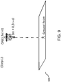
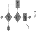
- FIGs. 9 to 13 depict the tilting of the pole in five different positions whilst FIGs. 14 to 18 depict the method steps performed in each of the five positions, respectively.
- the initialization procedure should be performed on an open-sky situation, with direct line-of-sight contact with GNSS satellites.
- the user presses 1420 the button and holds the position during a predetermined time interval T1, for example, of several seconds.
- T1 a predetermined time interval
- the algorithm aborts 1430 and awaits the button to be pressed.
- the data from the GNSS point 1 and the inertial sensor data are determined 1440.
- the LED blinks 1460 RED indicating the user to repeat this step, as depicted by the feedback arrow. Otherwise, the LED blinks 1450 GREEN and proceeds 1 to await the button pressing for the second position.
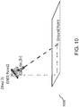
- FIG. 10 and FIG. 15 depict the pole in the second position 820, as the second GNSS position 2 is determined at orientation parameters ⁇ 2 and ⁇ 2.
- the user tilts the pole, in any direction, between 20 and 45 degrees.
- the user presses 1520 the button and holds the position during a predetermined time interval.
- the algorithm aborts 1530 and awaits the button to be pressed.
- the data from the GNSS point 2 and the inertial sensor data are determined.
- the LED blinks 1560 RED indicating the user to repeat this step, as depicted by the feedback arrow. Otherwise, the LED blinks 1550 GREEN and proceeds 2 to await the button pressing for the third position. Since the pole can be tilted in any direction, this gives the user flexibility in using the pole for position determination, considering the obstacles present in the particular measurement scenario.
- FIG. 11 and FIG. 16 depict the pole in the third position 830, as the third GNSS position 3 is determined at orientation parameters ⁇ 3 and ⁇ 3.
- the user tilts the pole in the opposite direction of the second position, or between 20 and 45 degrees from the vertical in the opposite direction.
- the user presses the button and holds the position during a predetermined time interval.
- the algorithm aborts 1630 and awaits the button to be pressed.
- the data from the GNSS point 3 and the inertial sensor data are determined.
- FIG. 12 and FIG. 17 depict the pole in the fourth position 840, as the fourth GNSS position 4 is determined at orientation parameters ⁇ 4 and ⁇ 4.
- the user tilts the pole, between 20 and 45 degrees, in a direction perpendicular to the axis drawn by the second and third positions of the previous steps.
- the user presses the button and holds the position during a predetermined time interval.
- the algorithm aborts 1730 and awaits the button to be pressed.
- the data from the GNSS point 4 and the inertial sensor data are determined.
- FIG. 13 and FIG. 18 depict the pole in the fifth position 850, as the fifth GNSS position 5 is determined at orientation parameters ⁇ 5 and ⁇ 5.
- the user tilts the pole in the opposite direction of the fourth position, between 20 and 45 degrees from the vertical in the opposite direction.
- the user presses the button and holds the position during a predetermined time interval.
- the algorithm aborts 1830 and awaits the button to be pressed.
- the data from the GNSS point 5 and the inertial sensor data are determined.
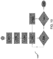
- FIG. 19 depicts the steps involved in position determination.
- a first ground point 140 position estimation is determined.
- the attitude angles heading, pitch, roll
- the bias of the inertial sensing means is determined.
- the first ground point position estimation is updated by taking into account the determined bias resulting in an accurate ground point position 140. This position is then stored in both the local memory storage as well as the internal memory storage 670. It is also made available to the external device.
- step 1950 it is determined whether the button is still pressed. In case negative, the ground point position is continually updated 1940.
- step 1960 it is determined whether the button is being pressed for a second predetermined period of time T2 smaller than T1, indicating that a new ground point position determination is desired.
- step 1970 a new first ground point determination is performed, as in step 1910, however now this estimation is immediately updated 1940 using the existing attitude angles and bias values.
- the process ends 1980 when the button is not being pressed anymore, indicating that no further position determination is desired.
- the button is pressed again for a longer predetermined duration T1
- the device starts a new initialization and bias estimation process as it is assumed that the scenario has changed and that the pole is under the influence of different electro-magnetic interference.
- all the steps of the position determination algorithm can be performed in real-time. In another aspect, some of the steps can be performed in a post-processing stage using all the data stored in the various storage means. Also, some or the entire position determination algorithm can be performed locally within the positioning device itself, or also the data exported to any external computing device for performing the required computations.
- the different aspects of the invention described enable fast yet accurate position determination for topographical applications which is resilient to magnetic fields by allowing the positioning pole to be used in any position (not just horizontal) thereby increasing the number of scenarios in which the tool can be used, resulting in a more versatile yet reliable surveying pole (which can be used in complicated environments, such as railways or energy power stations).
- an overall faster system initialization and inertial sensor calibration results, yielding a more efficient tool for position determination.
- the various means may comprise software modules residing in RAM memory, flash memory, ROM memory, EPROM memory, EEPROM memory, registers, hard disk, a removable disk, a CD-ROM, or any other form of storage medium known in the art.
- the various means may comprise logical blocks, modules, and circuits may be implemented or performed with a general purpose processor, a digital signal processor (DSP), and application specific integrated circuit (ASIC), a field programmable gate array (FPGA), or other programmable logic device, discrete gate or transistor logic, discrete hardware components, or any combination thereof designed to perform the functions described.
- DSP digital signal processor
- ASIC application specific integrated circuit
- FPGA field programmable gate array
- a general-purpose processor may be a microprocessor, but in the alternative, the processor may be any conventional processor, controller, microcontroller, or state machine.
- the various means may comprise computer-readable media including, but not limited to, magnetic storage devices (for example , hard disk, floppy disk, magnetic strips, etc.), optical disks (for example , compact disk (CD), digital versatile disk (DVD), etc.), smart cards, and flash memory devices (for example , EPROM, card, stick, key drive, etc.).
- various storage media described herein can represent one or more devices and/or other machine-readable media for storing information.
- the term machine-readable medium can include, without being limited to, various media capable of storing, containing, and/or carrying instruction(s) and/or data.
- a computer program product may include a computer readable medium having one or more instructions or codes operable to cause a computer to perform the functions described herein.
Landscapes
- Engineering & Computer Science (AREA)
- Radar, Positioning & Navigation (AREA)
- Remote Sensing (AREA)
- Physics & Mathematics (AREA)
- General Physics & Mathematics (AREA)
- Automation & Control Theory (AREA)
- Computer Networks & Wireless Communication (AREA)
- Navigation (AREA)
- Position Fixing By Use Of Radio Waves (AREA)
- Geophysics And Detection Of Objects (AREA)
Claims (15)
- Positioniermast (500) zur Bodenpunktpositionsbestimmung, umfassend eine Stange mit einem unteren Ende zum Anordnen an dem zu bestimmenden Bodenpunkt und ein Positionsbestimmungsmittel an ihrem oberen Ende, wobei das Positionsbestimmungsmittel (600) umfasst:Satellitenpositionierungsmittel (610, 620) zum Erfassen der geodätischen Koordinaten eines Referenzpunkts am oberen Ende bei einer bestimmten Mastneigung;Trägheitserfassungsmittel (630) zum Beschaffen von Trägheitsdaten des Referenzpunkts am oberen Ende, die der Mastneigung entsprechen; dadurch gekennzeichnet, dass die Positionsbestimmungsmittel umfassenVerarbeitungsmittel (640) zum Bestimmen der Koordinaten des Bodenpunkts als eine Funktion der Länge der Stange und der beschafften geodätischen Koordinaten und Trägheitsdaten, die mindestens drei verschiedenen Stangenneigungen entsprechen, wobei die Verarbeitungsmittel dazu eingerichtet sind, eine Vielzahl von Bodenpunktkandidaten als die Vielzahl von möglichen Schnittpunkten der vertikalen Projektion (570) mit der horizontalen Projektion (580) des oberen Endes des Masts zu definieren, die jeder Stangenneigung entspricht, und die endgültige Bodenpunktposition entspricht dem Kandidaten, der den mindestens drei verschiedenen Mastneigungen gemeinsam ist.
- Mast nach Anspruch 1, wobei das Positionsbestimmungsmittel ferner ein Speichermittel zum Speichern aller beschafften Daten und des Ergebnisses der Bestimmungen umfasst.
- Mast nach Anspruch 2, wobei das Satellitenpositionierungsmittel eine GNSS-Antenne und einen GNSS-Empfänger umfasst und wobei die geodätischen Koordinaten des Referenzpunkts am oberen Ende denjenigen der GNSS-Antenne entsprechen.
- Mast nach Anspruch 3, wobei das Verarbeitungsmittel ein Beschaffungsmittel zum Beschaffen der geodätischen Koordinaten von den Satellitenpositionierungsmitteln und zum Beschaffen der Trägheitsdaten von den Trägheitserfassungsmitteln umfasst.
- Mast nach Anspruch 4, wobei das Verarbeitungsmittel ein Datenverarbeitungsmittel zum Bestimmen der Koordinaten des Bodenpunkts unter Verwendung der Daten des Beschaffungsmittels umfasst, wobei die Bodenpunktposition als eine Funktion des Nickwinkels und des Rollwinkels des Masts bestimmt wird.
- Mast nach Anspruch 4, wobei das Verarbeitungsmittel ferner ein Zeitmarkierungsmittel zum Zeitmarkieren der Positionsdaten sowie von Trägheitsdaten umfasst und ferner ein Kommunikationsmittel zum Übermitteln der beschafften Daten und/oder des Ergebnisses der Bestimmungen an eine externe Vorrichtung umfasst und ferner Anzeigemittel zum Anzeigen, wann der Mast in eine neue Neigungslage geneigt werden soll, und zum Anzeigen umfasst, wann der Bodenpunkt bestimmt wurde.
- Verfahren zur Bodenpunktpositionsbestimmung durch einen Positioniermast (500), wobei der Positioniermast eine Stange mit einem unteren Ende zum Anordnen an dem zu bestimmenden Bodenpunkt und Positionsbestimmungsmittel (600) an ihrem oberen Ende umfasst, wobei das Verfahren eine Initialisierungsphase umfasst, umfassend:Beschaffen der geodätischen Koordinaten und der Trägheitsdaten eines Referenzpunkts am oberen Ende für mindestens drei verschiedene Stangenneigungen; dadurch gekennzeichnet, dass die Initialisierungsphase umfasstBestimmen der Koordinaten des Bodenpunkts als eine Funktion der Länge der Stange und der beschafften geodätischen Koordinaten und Trägheitsdaten, die mindestens drei verschiedenen Stangenneigungen entsprechen, und Definieren einer Vielzahl von Bodenpunktkandidaten als die Vielzahl von möglichen Schnittpunkten der vertikalen Projektion (570) mit der horizontalen Projektion (580) des oberen Endes des Masts, die jeder Stangenneigung entspricht, und die endgültige Bodenpunktposition entspricht dem Kandidaten, der den mindestens drei verschiedenen Mastneigungen gemeinsam ist.
- Verfahren nach Anspruch 7, wobei die mindestens drei verschiedenen Stangenneigungen das Neigen des oberen Endes des Masts umfassen, während das untere Ende für drei oder mindestens vier oder vorzugsweise fünf verschiedene Stangenneigungen an demselben Bodenpunkt festgehalten wird, wobei das obere Ende für den Fall von drei Neigungen bei jeder Neigung vorzugsweise den Ecken eines gleichseitigen Dreiecks entspricht, wobei das obere Ende für den Fall von vier Neigungen bei jeder Neigung vorzugsweise den Ecken eines Quadrats entspricht und wobei das obere Ende für den Fall von fünf Neigungen bei jeder Neigung vorzugsweise den Ecken eines Quadrats und seinem Mittelpunkt entspricht.
- Verfahren nach Anspruch 8, umfassend das Bestimmen des Nickwinkels und des Rollwinkels des Masts aus den Trägheitsdaten, die jeder Stangenneigung entsprechen, als eine Funktion der mittleren Beschleunigung, die in der x-Achse bzw. der y-Achse gemessen wird, und wobei die Bodenpunktposition auch als eine Funktion der Nick- und Rollwinkel bestimmt wird.
- Verfahren nach Anspruch 9, umfassend das Bestimmen des absoluten Kurswinkels des Masts auf der Grundlage des aktuellen Nickwinkels, des aktuellen Rollwinkels und der geodätischen Koordinaten eines vorherigen und aktuellen Bodenpunkts.
- Verfahren nach Anspruch 8, ferner umfassend einen Fehlerkorrekturmechanismus, der das Schätzen der Trägheitssensor-Abweichungswerte und das Subtrahieren derselben von den beschafften Trägheitsdatenwerten umfasst, wobei die Abweichungswerte Beschleunigungsmesser-Abweichungswerte und Kreisel-Abweichungswerte sind.
- Verfahren nach Anspruch 9, ferner umfassend eine nachfolgende Betriebsphase ohne geodätische Koordinaten und Inertialdatenerfassung, wobei die Bodenpunktposition als eine Funktion der Koordinaten eines vorherigen Bodenpunkts und der Nachverfolgung der Unterschiede in den Nick-, Roll- und Kurswinkeln bestimmt wird.
- Verfahren zum Herstellen eines verbesserten Vermessungsmastens aus einer herkömmlichen Vermessungsstange, wobei das Verfahren das Ersetzen aller elektronischen Vorrichtungen des herkömmlichen Masts durch ein einziges Positionsbestimmungsmittel nach Anspruch 1, das am oberen Ende des Masts angeordnet ist, umfasst.
- Computerprogramm, umfassend Anweisungen, die einmal auf einem Prozessor ausgeführt werden, zum Durchführen der Verfahrensschritte nach einem der Ansprüche 7 bis 13.
- Computerlesbares Medium, umfassend Anweisungen, die einmal auf einem Prozessor ausgeführt werden,zum Durchführen der Verfahrensschritte nach einem der Ansprüche 7 bis 13.
Applications Claiming Priority (1)
| Application Number | Priority Date | Filing Date | Title |
|---|---|---|---|
| PCT/EP2015/081433 WO2017114577A1 (en) | 2015-12-30 | 2015-12-30 | Improved surveying pole |
Publications (2)
| Publication Number | Publication Date |
|---|---|
| EP3397923A1 EP3397923A1 (de) | 2018-11-07 |
| EP3397923B1 true EP3397923B1 (de) | 2019-05-29 |
Family
ID=55083403
Family Applications (1)
| Application Number | Title | Priority Date | Filing Date |
|---|---|---|---|
| EP15823178.7A Active EP3397923B1 (de) | 2015-12-30 | 2015-12-30 | Verbesserter vermessungsstab |
Country Status (5)
| Country | Link |
|---|---|
| US (1) | US10704902B2 (de) |
| EP (1) | EP3397923B1 (de) |
| CN (1) | CN108700416B (de) |
| ES (1) | ES2742894T3 (de) |
| WO (1) | WO2017114577A1 (de) |
Families Citing this family (14)
| Publication number | Priority date | Publication date | Assignee | Title |
|---|---|---|---|---|
| WO2017205839A1 (en) * | 2016-05-27 | 2017-11-30 | Javad Gnss, Inc | Magnetic locator for gnss device |
| WO2019051134A1 (en) * | 2017-09-06 | 2019-03-14 | Howell Asset Locator, Llc | TECHNOLOGIES FOR MONITORING AND LOCATING UNDERGROUND ASSETS |
| EP3460398A1 (de) | 2017-09-22 | 2019-03-27 | Trimble Inc. | Verfahren, vorrichtungen und computerprogramme zur bestimmung der bewegungsrichtung einer achse eines starren körpers |
| JP7088719B2 (ja) * | 2018-03-30 | 2022-06-21 | 株式会社トプコン | Gnss装置 |
| EP3660451B1 (de) * | 2018-11-28 | 2022-04-27 | Hexagon Technology Center GmbH | Intelligentes stationierungs-modul |
| EP3693698A1 (de) * | 2019-02-05 | 2020-08-12 | Leica Geosystems AG | Vermessungsgerät mit ereignisbasierter kamera |
| CN110412637B (zh) * | 2019-07-25 | 2020-07-28 | 广州吉欧电子科技有限公司 | 基于多传感器融合的gnss倾斜测量系统及方法 |
| CN110411431A (zh) * | 2019-08-12 | 2019-11-05 | 陈瑞琦 | 基于北斗双天线系统的高大架体垂直度监测系统及方法 |
| CN113093256B (zh) | 2019-12-23 | 2024-02-13 | 上海华测导航技术股份有限公司 | 一种gnss/imu测绘系统和方法 |
| CN111736181A (zh) * | 2020-05-08 | 2020-10-02 | 广州南方卫星导航仪器有限公司 | 高精度测绘型gnss接收机自检方法、电子设备、介质及系统 |
| CN112284356B (zh) * | 2020-09-29 | 2023-01-24 | 深圳冰河导航科技有限公司 | 一种基于rtk的墙角坐标自动测量方法 |
| US11921222B1 (en) * | 2021-04-15 | 2024-03-05 | Corey CRAIG | Intelligent planting apparatus |
| CN116067434B (zh) * | 2023-03-07 | 2023-07-04 | 中铁大桥局集团有限公司 | 一种大节段桥梁的可视化安装系统和安装方法 |
| CN117233780A (zh) * | 2023-09-05 | 2023-12-15 | 上海司南卫星导航技术股份有限公司 | 一种测量系统的控制方法、测量系统及计算机可读介质 |
Family Cites Families (12)
| Publication number | Priority date | Publication date | Assignee | Title |
|---|---|---|---|---|
| US5929807A (en) * | 1997-03-07 | 1999-07-27 | Trimble Navigation Limited | Method and apparatus for precision location of GPS survey tilt pole |
| US6633256B2 (en) * | 2001-08-24 | 2003-10-14 | Topcon Gps Llc | Methods and systems for improvement of measurement efficiency in surveying |
| EP1645846A1 (de) * | 2004-10-11 | 2006-04-12 | Leica Geosystems AG | Geodätisches positionsbestimmungssystem |
| US7541974B2 (en) * | 2005-12-15 | 2009-06-02 | Trimble Navigation Limited | Managed traverse system and method to acquire accurate survey data in absence of precise GPS data |
| US20090024325A1 (en) * | 2007-07-19 | 2009-01-22 | Scherzinger Bruno M | AINS enhanced survey instrument |
| JP6002126B2 (ja) * | 2010-06-25 | 2016-10-05 | トリンブル ナビゲーション リミテッドTrimble Navigation Limited | 画像ベースの測位のための方法および装置 |
| US8698695B2 (en) * | 2011-07-28 | 2014-04-15 | Deere & Company | Antenna system for use in agricultural fields or other work areas |
| EP2722647A1 (de) * | 2012-10-18 | 2014-04-23 | Leica Geosystems AG | Überwachungssystem und Verfahren |
| EP3182066B1 (de) * | 2015-12-17 | 2018-07-04 | Leica Geosystems AG | Vermessungsstab |
| EP3306347B1 (de) * | 2016-10-10 | 2022-07-06 | Trimble Inc. | System und verfahren zur registrierung von messpunkten |
| US11129361B2 (en) * | 2018-03-21 | 2021-09-28 | Tagacow LLC | System and method for managing livestock using radio frequency device |
| EP3598176A1 (de) * | 2018-07-20 | 2020-01-22 | Trimble Nantes S.A.S. | Verfahren zur georäumlichen positionierung und tragbare positionierungsvorrichtungen dafür |
-
2015
- 2015-12-30 CN CN201580085841.XA patent/CN108700416B/zh active Active
- 2015-12-30 US US16/075,912 patent/US10704902B2/en active Active
- 2015-12-30 ES ES15823178T patent/ES2742894T3/es active Active
- 2015-12-30 EP EP15823178.7A patent/EP3397923B1/de active Active
- 2015-12-30 WO PCT/EP2015/081433 patent/WO2017114577A1/en active Application Filing
Non-Patent Citations (1)
| Title |
|---|
| None * |
Also Published As
| Publication number | Publication date |
|---|---|
| EP3397923A1 (de) | 2018-11-07 |
| CN108700416A (zh) | 2018-10-23 |
| US10704902B2 (en) | 2020-07-07 |
| ES2742894T3 (es) | 2020-02-17 |
| CN108700416B (zh) | 2019-11-22 |
| WO2017114577A1 (en) | 2017-07-06 |
| US20200166338A1 (en) | 2020-05-28 |
Similar Documents
| Publication | Publication Date | Title |
|---|---|---|
| EP3397923B1 (de) | Verbesserter vermessungsstab | |
| US8781737B2 (en) | Spatial alignment determination for an inertial measurement unit (IMU) | |
| US11428823B2 (en) | Methods, apparatuses, and computer programs for estimating the heading of an axis of a rigid body | |
| US10309786B2 (en) | Navigational and location determination system | |
| RU2395061C1 (ru) | Способ определения местоположения подвижных объектов и комплексированная навигационная система для его реализации | |
| CN109269471A (zh) | 一种新型gnss接收机倾斜测量系统及方法 | |
| CN102257358B (zh) | 使用惯性测量单元确定真北方向的指向的方法 | |
| WO2012049492A1 (en) | Positioning system | |
| JP2007155584A (ja) | 慣性航法システム | |
| CN110057356B (zh) | 一种隧道内车辆定位方法及装置 | |
| RU2768087C2 (ru) | Транспортное средство для подземных горных работ и способ его ориентации | |
| US20140249750A1 (en) | Navigational and location determination system | |
| US10006770B2 (en) | Remote location determination system | |
| RU100232U1 (ru) | Комплексированная навигационная система для определения координат подвижных наземных объектов | |
| CN105759292B (zh) | 一种差分gps与机器人的相对位置参数标定方法及系统 | |
| US10429185B2 (en) | Indoor rotation sensor and directional sensor for determining the heading angle of portable device | |
| Prusaczyk et al. | GPS-free navigation based on using inertial and odometry, data fusion and map matching algorithm | |
| RU2250993C1 (ru) | Способ определения азимута и зенитного угла скважины | |
| RU2674535C1 (ru) | Способ полевой калибровки магнитного компаса | |
| RU2606673C1 (ru) | Устройство для определения направления на географический север | |
| Hu et al. | Novel research on improving global positioning system accuracy in the pedestrian integrated navigation monitoring system | |
| CN117705097A (zh) | 一种棱镜杆装置、地物碎部点测量方法、设备及介质 | |
| Uradzinski et al. | Checking the accuracy of an inertial-based pedestrian navigation system with a drone | |
| Yuan et al. | INS aided GPS integer ambiguity resolution and real time vehicle attitude determination | |
| Kinnunen | Verification of a vehicle navigation system |
Legal Events
| Date | Code | Title | Description |
|---|---|---|---|
| STAA | Information on the status of an ep patent application or granted ep patent |
Free format text: STATUS: THE INTERNATIONAL PUBLICATION HAS BEEN MADE |
|
| PUAI | Public reference made under article 153(3) epc to a published international application that has entered the european phase |
Free format text: ORIGINAL CODE: 0009012 |
|
| STAA | Information on the status of an ep patent application or granted ep patent |
Free format text: STATUS: REQUEST FOR EXAMINATION WAS MADE |
|
| 17P | Request for examination filed |
Effective date: 20180711 |
|
| AK | Designated contracting states |
Kind code of ref document: A1 Designated state(s): AL AT BE BG CH CY CZ DE DK EE ES FI FR GB GR HR HU IE IS IT LI LT LU LV MC MK MT NL NO PL PT RO RS SE SI SK SM TR |
|
| AX | Request for extension of the european patent |
Extension state: BA ME |
|
| GRAP | Despatch of communication of intention to grant a patent |
Free format text: ORIGINAL CODE: EPIDOSNIGR1 |
|
| STAA | Information on the status of an ep patent application or granted ep patent |
Free format text: STATUS: GRANT OF PATENT IS INTENDED |
|
| DAV | Request for validation of the european patent (deleted) | ||
| DAX | Request for extension of the european patent (deleted) | ||
| INTG | Intention to grant announced |
Effective date: 20190304 |
|
| GRAS | Grant fee paid |
Free format text: ORIGINAL CODE: EPIDOSNIGR3 |
|
| GRAA | (expected) grant |
Free format text: ORIGINAL CODE: 0009210 |
|
| STAA | Information on the status of an ep patent application or granted ep patent |
Free format text: STATUS: THE PATENT HAS BEEN GRANTED |
|
| AK | Designated contracting states |
Kind code of ref document: B1 Designated state(s): AL AT BE BG CH CY CZ DE DK EE ES FI FR GB GR HR HU IE IS IT LI LT LU LV MC MK MT NL NO PL PT RO RS SE SI SK SM TR |
|
| REG | Reference to a national code |
Ref country code: GB Ref legal event code: FG4D |
|
| REG | Reference to a national code |
Ref country code: CH Ref legal event code: EP |
|
| REG | Reference to a national code |
Ref country code: AT Ref legal event code: REF Ref document number: 1138533 Country of ref document: AT Kind code of ref document: T Effective date: 20190615 |
|
| REG | Reference to a national code |
Ref country code: DE Ref legal event code: R096 Ref document number: 602015031184 Country of ref document: DE |
|
| REG | Reference to a national code |
Ref country code: IE Ref legal event code: FG4D |
|
| REG | Reference to a national code |
Ref country code: SE Ref legal event code: TRGR |
|
| REG | Reference to a national code |
Ref country code: NL Ref legal event code: MP Effective date: 20190529 |
|
| REG | Reference to a national code |
Ref country code: LT Ref legal event code: MG4D |
|
| PG25 | Lapsed in a contracting state [announced via postgrant information from national office to epo] |
Ref country code: LT Free format text: LAPSE BECAUSE OF FAILURE TO SUBMIT A TRANSLATION OF THE DESCRIPTION OR TO PAY THE FEE WITHIN THE PRESCRIBED TIME-LIMIT Effective date: 20190529 Ref country code: FI Free format text: LAPSE BECAUSE OF FAILURE TO SUBMIT A TRANSLATION OF THE DESCRIPTION OR TO PAY THE FEE WITHIN THE PRESCRIBED TIME-LIMIT Effective date: 20190529 Ref country code: AL Free format text: LAPSE BECAUSE OF FAILURE TO SUBMIT A TRANSLATION OF THE DESCRIPTION OR TO PAY THE FEE WITHIN THE PRESCRIBED TIME-LIMIT Effective date: 20190529 Ref country code: PT Free format text: LAPSE BECAUSE OF FAILURE TO SUBMIT A TRANSLATION OF THE DESCRIPTION OR TO PAY THE FEE WITHIN THE PRESCRIBED TIME-LIMIT Effective date: 20190930 Ref country code: NO Free format text: LAPSE BECAUSE OF FAILURE TO SUBMIT A TRANSLATION OF THE DESCRIPTION OR TO PAY THE FEE WITHIN THE PRESCRIBED TIME-LIMIT Effective date: 20190829 Ref country code: HR Free format text: LAPSE BECAUSE OF FAILURE TO SUBMIT A TRANSLATION OF THE DESCRIPTION OR TO PAY THE FEE WITHIN THE PRESCRIBED TIME-LIMIT Effective date: 20190529 |
|
| PG25 | Lapsed in a contracting state [announced via postgrant information from national office to epo] |
Ref country code: BG Free format text: LAPSE BECAUSE OF FAILURE TO SUBMIT A TRANSLATION OF THE DESCRIPTION OR TO PAY THE FEE WITHIN THE PRESCRIBED TIME-LIMIT Effective date: 20190829 Ref country code: LV Free format text: LAPSE BECAUSE OF FAILURE TO SUBMIT A TRANSLATION OF THE DESCRIPTION OR TO PAY THE FEE WITHIN THE PRESCRIBED TIME-LIMIT Effective date: 20190529 Ref country code: GR Free format text: LAPSE BECAUSE OF FAILURE TO SUBMIT A TRANSLATION OF THE DESCRIPTION OR TO PAY THE FEE WITHIN THE PRESCRIBED TIME-LIMIT Effective date: 20190830 Ref country code: RS Free format text: LAPSE BECAUSE OF FAILURE TO SUBMIT A TRANSLATION OF THE DESCRIPTION OR TO PAY THE FEE WITHIN THE PRESCRIBED TIME-LIMIT Effective date: 20190529 |
|
| REG | Reference to a national code |
Ref country code: AT Ref legal event code: MK05 Ref document number: 1138533 Country of ref document: AT Kind code of ref document: T Effective date: 20190529 |
|
| PG25 | Lapsed in a contracting state [announced via postgrant information from national office to epo] |
Ref country code: EE Free format text: LAPSE BECAUSE OF FAILURE TO SUBMIT A TRANSLATION OF THE DESCRIPTION OR TO PAY THE FEE WITHIN THE PRESCRIBED TIME-LIMIT Effective date: 20190529 Ref country code: RO Free format text: LAPSE BECAUSE OF FAILURE TO SUBMIT A TRANSLATION OF THE DESCRIPTION OR TO PAY THE FEE WITHIN THE PRESCRIBED TIME-LIMIT Effective date: 20190529 Ref country code: AT Free format text: LAPSE BECAUSE OF FAILURE TO SUBMIT A TRANSLATION OF THE DESCRIPTION OR TO PAY THE FEE WITHIN THE PRESCRIBED TIME-LIMIT Effective date: 20190529 Ref country code: NL Free format text: LAPSE BECAUSE OF FAILURE TO SUBMIT A TRANSLATION OF THE DESCRIPTION OR TO PAY THE FEE WITHIN THE PRESCRIBED TIME-LIMIT Effective date: 20190529 Ref country code: CZ Free format text: LAPSE BECAUSE OF FAILURE TO SUBMIT A TRANSLATION OF THE DESCRIPTION OR TO PAY THE FEE WITHIN THE PRESCRIBED TIME-LIMIT Effective date: 20190529 Ref country code: DK Free format text: LAPSE BECAUSE OF FAILURE TO SUBMIT A TRANSLATION OF THE DESCRIPTION OR TO PAY THE FEE WITHIN THE PRESCRIBED TIME-LIMIT Effective date: 20190529 Ref country code: SK Free format text: LAPSE BECAUSE OF FAILURE TO SUBMIT A TRANSLATION OF THE DESCRIPTION OR TO PAY THE FEE WITHIN THE PRESCRIBED TIME-LIMIT Effective date: 20190529 |
|
| REG | Reference to a national code |
Ref country code: ES Ref legal event code: FG2A Ref document number: 2742894 Country of ref document: ES Kind code of ref document: T3 Effective date: 20200217 |
|
| PG25 | Lapsed in a contracting state [announced via postgrant information from national office to epo] |
Ref country code: SM Free format text: LAPSE BECAUSE OF FAILURE TO SUBMIT A TRANSLATION OF THE DESCRIPTION OR TO PAY THE FEE WITHIN THE PRESCRIBED TIME-LIMIT Effective date: 20190529 |
|
| REG | Reference to a national code |
Ref country code: DE Ref legal event code: R097 Ref document number: 602015031184 Country of ref document: DE |
|
| PG25 | Lapsed in a contracting state [announced via postgrant information from national office to epo] |
Ref country code: TR Free format text: LAPSE BECAUSE OF FAILURE TO SUBMIT A TRANSLATION OF THE DESCRIPTION OR TO PAY THE FEE WITHIN THE PRESCRIBED TIME-LIMIT Effective date: 20190529 |
|
| PLBE | No opposition filed within time limit |
Free format text: ORIGINAL CODE: 0009261 |
|
| STAA | Information on the status of an ep patent application or granted ep patent |
Free format text: STATUS: NO OPPOSITION FILED WITHIN TIME LIMIT |
|
| PG25 | Lapsed in a contracting state [announced via postgrant information from national office to epo] |
Ref country code: PL Free format text: LAPSE BECAUSE OF FAILURE TO SUBMIT A TRANSLATION OF THE DESCRIPTION OR TO PAY THE FEE WITHIN THE PRESCRIBED TIME-LIMIT Effective date: 20190529 |
|
| 26N | No opposition filed |
Effective date: 20200303 |
|
| REG | Reference to a national code |
Ref country code: BE Ref legal event code: MM Effective date: 20191231 |
|
| PG25 | Lapsed in a contracting state [announced via postgrant information from national office to epo] |
Ref country code: MC Free format text: LAPSE BECAUSE OF FAILURE TO SUBMIT A TRANSLATION OF THE DESCRIPTION OR TO PAY THE FEE WITHIN THE PRESCRIBED TIME-LIMIT Effective date: 20190529 |
|
| PG25 | Lapsed in a contracting state [announced via postgrant information from national office to epo] |
Ref country code: LU Free format text: LAPSE BECAUSE OF NON-PAYMENT OF DUE FEES Effective date: 20191230 |
|
| PG25 | Lapsed in a contracting state [announced via postgrant information from national office to epo] |
Ref country code: BE Free format text: LAPSE BECAUSE OF NON-PAYMENT OF DUE FEES Effective date: 20191231 |
|
| PG25 | Lapsed in a contracting state [announced via postgrant information from national office to epo] |
Ref country code: CY Free format text: LAPSE BECAUSE OF FAILURE TO SUBMIT A TRANSLATION OF THE DESCRIPTION OR TO PAY THE FEE WITHIN THE PRESCRIBED TIME-LIMIT Effective date: 20190529 |
|
| PG25 | Lapsed in a contracting state [announced via postgrant information from national office to epo] |
Ref country code: IS Free format text: LAPSE BECAUSE OF FAILURE TO SUBMIT A TRANSLATION OF THE DESCRIPTION OR TO PAY THE FEE WITHIN THE PRESCRIBED TIME-LIMIT Effective date: 20190929 |
|
| PG25 | Lapsed in a contracting state [announced via postgrant information from national office to epo] |
Ref country code: HU Free format text: LAPSE BECAUSE OF FAILURE TO SUBMIT A TRANSLATION OF THE DESCRIPTION OR TO PAY THE FEE WITHIN THE PRESCRIBED TIME-LIMIT; INVALID AB INITIO Effective date: 20151230 Ref country code: MT Free format text: LAPSE BECAUSE OF FAILURE TO SUBMIT A TRANSLATION OF THE DESCRIPTION OR TO PAY THE FEE WITHIN THE PRESCRIBED TIME-LIMIT Effective date: 20190529 |
|
| PG25 | Lapsed in a contracting state [announced via postgrant information from national office to epo] |
Ref country code: SI Free format text: LAPSE BECAUSE OF FAILURE TO SUBMIT A TRANSLATION OF THE DESCRIPTION OR TO PAY THE FEE WITHIN THE PRESCRIBED TIME-LIMIT Effective date: 20190529 |
|
| PG25 | Lapsed in a contracting state [announced via postgrant information from national office to epo] |
Ref country code: MK Free format text: LAPSE BECAUSE OF FAILURE TO SUBMIT A TRANSLATION OF THE DESCRIPTION OR TO PAY THE FEE WITHIN THE PRESCRIBED TIME-LIMIT Effective date: 20190529 |
|
| PGFP | Annual fee paid to national office [announced via postgrant information from national office to epo] |
Ref country code: SE Payment date: 20221216 Year of fee payment: 8 Ref country code: FR Payment date: 20221216 Year of fee payment: 8 |
|
| PGFP | Annual fee paid to national office [announced via postgrant information from national office to epo] |
Ref country code: IT Payment date: 20221212 Year of fee payment: 8 |
|
| PGFP | Annual fee paid to national office [announced via postgrant information from national office to epo] |
Ref country code: ES Payment date: 20240116 Year of fee payment: 9 Ref country code: IE Payment date: 20240116 Year of fee payment: 9 |
|
| PGFP | Annual fee paid to national office [announced via postgrant information from national office to epo] |
Ref country code: DE Payment date: 20240117 Year of fee payment: 9 Ref country code: GB Payment date: 20240116 Year of fee payment: 9 Ref country code: CH Payment date: 20240119 Year of fee payment: 9 |