EP3397550B1 - Motorcycle with multi-configuration chassis - Google Patents
Motorcycle with multi-configuration chassis Download PDFInfo
- Publication number
- EP3397550B1 EP3397550B1 EP16849916.8A EP16849916A EP3397550B1 EP 3397550 B1 EP3397550 B1 EP 3397550B1 EP 16849916 A EP16849916 A EP 16849916A EP 3397550 B1 EP3397550 B1 EP 3397550B1
- Authority
- EP
- European Patent Office
- Prior art keywords
- assembly
- rigid
- chassis
- hinge
- end connected
- Prior art date
- Legal status (The legal status is an assumption and is not a legal conclusion. Google has not performed a legal analysis and makes no representation as to the accuracy of the status listed.)
- Active
Links
Images


Classifications
-
- B—PERFORMING OPERATIONS; TRANSPORTING
- B62—LAND VEHICLES FOR TRAVELLING OTHERWISE THAN ON RAILS
- B62K—CYCLES; CYCLE FRAMES; CYCLE STEERING DEVICES; RIDER-OPERATED TERMINAL CONTROLS SPECIALLY ADAPTED FOR CYCLES; CYCLE AXLE SUSPENSIONS; CYCLE SIDECARS, FORECARS, OR THE LIKE
- B62K25/00—Axle suspensions
- B62K25/04—Axle suspensions for mounting axles resiliently on cycle frame or fork
- B62K25/06—Axle suspensions for mounting axles resiliently on cycle frame or fork with telescopic fork, e.g. including auxiliary rocking arms
- B62K25/08—Axle suspensions for mounting axles resiliently on cycle frame or fork with telescopic fork, e.g. including auxiliary rocking arms for front wheel
-
- B—PERFORMING OPERATIONS; TRANSPORTING
- B62—LAND VEHICLES FOR TRAVELLING OTHERWISE THAN ON RAILS
- B62J—CYCLE SADDLES OR SEATS; AUXILIARY DEVICES OR ACCESSORIES SPECIALLY ADAPTED TO CYCLES AND NOT OTHERWISE PROVIDED FOR, e.g. ARTICLE CARRIERS OR CYCLE PROTECTORS
- B62J1/00—Saddles or other seats for cycles; Arrangement thereof; Component parts
- B62J1/12—Box-shaped seats; Bench-type seats, e.g. dual or twin seats
-
- B—PERFORMING OPERATIONS; TRANSPORTING
- B62—LAND VEHICLES FOR TRAVELLING OTHERWISE THAN ON RAILS
- B62K—CYCLES; CYCLE FRAMES; CYCLE STEERING DEVICES; RIDER-OPERATED TERMINAL CONTROLS SPECIALLY ADAPTED FOR CYCLES; CYCLE AXLE SUSPENSIONS; CYCLE SIDECARS, FORECARS, OR THE LIKE
- B62K11/00—Motorcycles, engine-assisted cycles or motor scooters with one or two wheels
- B62K11/02—Frames
- B62K11/04—Frames characterised by the engine being between front and rear wheels
-
- B—PERFORMING OPERATIONS; TRANSPORTING
- B62—LAND VEHICLES FOR TRAVELLING OTHERWISE THAN ON RAILS
- B62K—CYCLES; CYCLE FRAMES; CYCLE STEERING DEVICES; RIDER-OPERATED TERMINAL CONTROLS SPECIALLY ADAPTED FOR CYCLES; CYCLE AXLE SUSPENSIONS; CYCLE SIDECARS, FORECARS, OR THE LIKE
- B62K25/00—Axle suspensions
- B62K25/04—Axle suspensions for mounting axles resiliently on cycle frame or fork
-
- B—PERFORMING OPERATIONS; TRANSPORTING
- B62—LAND VEHICLES FOR TRAVELLING OTHERWISE THAN ON RAILS
- B62K—CYCLES; CYCLE FRAMES; CYCLE STEERING DEVICES; RIDER-OPERATED TERMINAL CONTROLS SPECIALLY ADAPTED FOR CYCLES; CYCLE AXLE SUSPENSIONS; CYCLE SIDECARS, FORECARS, OR THE LIKE
- B62K25/00—Axle suspensions
- B62K25/04—Axle suspensions for mounting axles resiliently on cycle frame or fork
- B62K25/28—Axle suspensions for mounting axles resiliently on cycle frame or fork with pivoted chain-stay
- B62K25/283—Axle suspensions for mounting axles resiliently on cycle frame or fork with pivoted chain-stay for cycles without a pedal crank, e.g. motorcycles
-
- G—PHYSICS
- G06—COMPUTING OR CALCULATING; COUNTING
- G06F—ELECTRIC DIGITAL DATA PROCESSING
- G06F3/00—Input arrangements for transferring data to be processed into a form capable of being handled by the computer; Output arrangements for transferring data from processing unit to output unit, e.g. interface arrangements
- G06F3/01—Input arrangements or combined input and output arrangements for interaction between user and computer
- G06F3/03—Arrangements for converting the position or the displacement of a member into a coded form
- G06F3/033—Pointing devices displaced or positioned by the user, e.g. mice, trackballs, pens or joysticks; Accessories therefor
- G06F3/0354—Pointing devices displaced or positioned by the user, e.g. mice, trackballs, pens or joysticks; Accessories therefor with detection of two-dimensional [2D] relative movements between the device, or an operating part thereof, and a plane or surface, e.g. 2D mice, trackballs, pens or pucks
- G06F3/03543—Mice or pucks
-
- B—PERFORMING OPERATIONS; TRANSPORTING
- B60—VEHICLES IN GENERAL
- B60G—VEHICLE SUSPENSION ARRANGEMENTS
- B60G2300/00—Indexing codes relating to the type of vehicle
- B60G2300/12—Cycles; Motorcycles
-
- B—PERFORMING OPERATIONS; TRANSPORTING
- B62—LAND VEHICLES FOR TRAVELLING OTHERWISE THAN ON RAILS
- B62J—CYCLE SADDLES OR SEATS; AUXILIARY DEVICES OR ACCESSORIES SPECIALLY ADAPTED TO CYCLES AND NOT OTHERWISE PROVIDED FOR, e.g. ARTICLE CARRIERS OR CYCLE PROTECTORS
- B62J1/00—Saddles or other seats for cycles; Arrangement thereof; Component parts
- B62J1/08—Frames for saddles; Connections between saddle frames and seat pillars; Seat pillars
- B62J2001/085—Seat pillars having mechanisms to vary seat height, independently of the cycle frame
-
- B—PERFORMING OPERATIONS; TRANSPORTING
- B62—LAND VEHICLES FOR TRAVELLING OTHERWISE THAN ON RAILS
- B62K—CYCLES; CYCLE FRAMES; CYCLE STEERING DEVICES; RIDER-OPERATED TERMINAL CONTROLS SPECIALLY ADAPTED FOR CYCLES; CYCLE AXLE SUSPENSIONS; CYCLE SIDECARS, FORECARS, OR THE LIKE
- B62K25/00—Axle suspensions
- B62K25/04—Axle suspensions for mounting axles resiliently on cycle frame or fork
- B62K2025/044—Suspensions with automatic adjustment
-
- B—PERFORMING OPERATIONS; TRANSPORTING
- B62—LAND VEHICLES FOR TRAVELLING OTHERWISE THAN ON RAILS
- B62K—CYCLES; CYCLE FRAMES; CYCLE STEERING DEVICES; RIDER-OPERATED TERMINAL CONTROLS SPECIALLY ADAPTED FOR CYCLES; CYCLE AXLE SUSPENSIONS; CYCLE SIDECARS, FORECARS, OR THE LIKE
- B62K25/00—Axle suspensions
- B62K25/04—Axle suspensions for mounting axles resiliently on cycle frame or fork
- B62K2025/045—Suspensions with ride-height adjustment
-
- B—PERFORMING OPERATIONS; TRANSPORTING
- B62—LAND VEHICLES FOR TRAVELLING OTHERWISE THAN ON RAILS
- B62K—CYCLES; CYCLE FRAMES; CYCLE STEERING DEVICES; RIDER-OPERATED TERMINAL CONTROLS SPECIALLY ADAPTED FOR CYCLES; CYCLE AXLE SUSPENSIONS; CYCLE SIDECARS, FORECARS, OR THE LIKE
- B62K2201/00—Springs used in cycle frames or parts thereof
- B62K2201/04—Helical springs
-
- G—PHYSICS
- G06—COMPUTING OR CALCULATING; COUNTING
- G06F—ELECTRIC DIGITAL DATA PROCESSING
- G06F2203/00—Indexing scheme relating to G06F3/00 - G06F3/048
- G06F2203/033—Indexing scheme relating to G06F3/033
- G06F2203/0333—Ergonomic shaped mouse for one hand
Definitions
- the invention relates to the motorcycling sector.
- the invention relates to a motorcycle with multi-configuration chassis comprising kinematic mechanism assemblies by means of which the configuration of the motorcycle can be changed.
- mutatis mutandis to other motor- or pedal-driven vehicles, such as bicycles, tricycles, etc.
- the invention also relates to a multi-body kinematic mechanism for a rear fork assembly of a motorcycle having a rigid chassis, adapted to allow the configuration of the motorcycle to be varied.
- WO 2010/079093 A1 discloses in accordance with the preamble of claim 1, a motorcycle with multi-configuration chassis adapted to allow three adjustments selected from the following: saddle assembly tilt, front fork assembly lengthening, rear fork assembly lengthening.
- JP S60 234087 A discloses a motorcycle having the possibility of changing the asset of a motorcycle during movement, to improve the response to sudden accelerations or decelerations by acting essentially on the adjustment and compensation of the response of the front and rear shock absorbers, when the motorcycle is in motion, for example in order to compensate for the forward overhang movements, to which the user is subjected, during braking.
- the object of the invention is to define a motorcycle with multi-configuration chassis that allows the configuration of the motorcycle to be easily and rapidly changed, without having to modify the transmission or the suspensions of the vehicle.
- the object of the invention is achieved with a motorcycle with multi-configuration chassis according to the independent claim 1.
- the main advantage of the present invention lies in the fact that by combining the various adjustments allowed by variation of the length of a hydraulic or electric cylinder belonging to the different kinematic mechanisms associated with the front fork, rear fork and saddle assembly, a large number of configurations of the motorcycle are obtained.
- the extension or retraction of a hydraulic or electric cylinder belonging to said kinematic mechanisms allows an increase or a decrease of the pitch of the motorcycle and/or a decrease or lowering of the height of the saddle from the ground to be obtained.
- a motorcycle with multi-configuration chassis comprises:
- the engine of the motorcycle is connected to the rigid chassis Z6 in the points M2, M3 and M7.
- the output pinion M1 of the engine transmits motion to the double pinion A2 by means of the chain A1.
- the double pinion rotates mounted on a shaft in the point E, the shaft is housed on bushings fixed in the points M8 in the rigid chassis and in the points M9 in the rear fork D.
- the seats M8 and M9 are concentric to the point E.
- the double pinion transmits motion to the wheel rotatable with axle in the point D1.
- Figs. 5, 6, 7 and 8 schematically show the front fork, rear fork and saddle assemblies, and the structural diagrams of their kinematic mechanisms for adjustment.
- the tilt of the fork F1 of the front wheel is implemented by means of varying the length of the rod Q connected to the chassis by means of the hinge P.
- the rod Q can either be a hydraulic or electric cylinder or any other linear actuating means that allows the rod Q to extend or retract.
- the rod with variable length Q is connected to the rigid body V for supporting the forks by means of the connection V3.
- the body V by means of the bearings V1 and V2, acts both as axial and radial support for the front fork assembly F1 and handlebar mounting Z1, better represented in Figs. 9, 10 and 11 .
- the body V in jargon "steering head", is anchored to the forks and to the handlebar mounting through the plates Z2 and Z3 represented in Fig. 9 .
- pin Z4 that connects the body V to the fork F1-fork plate Z2, Z3 and handlebar mounting Z1 assembly.
- the front forks are adjustable in length.
- the cylinder Z7 incorporates a shock absorber formed by the cylinder Z8, by the stem Z9 and by the spring Z10.
- the actuator that moves the shock absorber can be a hydraulic cylinder, such as the component Z9, or can be electric, or implemented with any other linear system of known type.
- the rear fork assembly D illustrated in Fig. 8 is connected to the rigid chassis assembly by means of the points M and E.
- the rear fork indicated with the letter D is hinged to the rigid chassis assembly in the fulcrum E.
- the fork schematized as rigid body, rotates around the point E by means of the rod with variable length indicated with the letter A.
- the fork D is hinged to the rod A by means of the hinge B.
- the rod A variable in length, is a hydraulic cylinder (variable rod) that can also be an electric cylinder or an automatic linear guide, according to the manufacturer's needs.
- the extension or retraction of the rod A allows rotation of the fork D, which determines an increase or decrease of the pitch of the motorcycle and/or a decrease or lowering of the height of the saddle from the ground, this latter also being adjustable by varying the configuration of the front forks.
- the rod A which for simplicity is identified with the name of the cylinder, is connected to the rigid body N by means of the hinge O.
- the rigid body N is hinged to the rigid chassis assembly by means of the point M.
- the rigid body N by means of the hinge H, is connected to the rod with variable length indicated with the letter F.
- the rod with variable length F is the rear shock absorber of the motorcycle.
- the shock absorber is connected to the rigid body which is the fork D, by means of the hinge M5.
- the shock absorber F exerts a resistant moment around the fulcrum E through to the arm M6 of the fork D. Once the travel of the cylinder A has been blocked, the kinematic mechanism allows the wheel to move so as to compress the shock absorber F.
- the kinematic mechanism also works if the positions of the cylinder A and the shock absorber F are inverted, so that the cylinder A takes the position of the shock absorber F and vice versa.
- shock absorber which in the configuration indicated in Figs. 7 and 8 , is a shock absorber that works in compression, i.e., it is compressed, while with the second construction method, which can in any case be implemented with the same kinematic mechanism, it works in traction, i.e., it is extended.
- the saddle A4 rotates around the fulcrum M, connected to the rigid chassis Z6, as illustrated in Figs. 4 , 7 and 8 , through the rod with variable length I, which can be a cylinder or a variable linear element.
- the rod I is hinged in the point C connected to the rigid chassis and in the point I1 connected to the saddle A4.
Landscapes
- Engineering & Computer Science (AREA)
- Mechanical Engineering (AREA)
- General Engineering & Computer Science (AREA)
- Theoretical Computer Science (AREA)
- Human Computer Interaction (AREA)
- Physics & Mathematics (AREA)
- General Physics & Mathematics (AREA)
- Axle Suspensions And Sidecars For Cycles (AREA)
- Automatic Cycles, And Cycles In General (AREA)
Description
- The invention relates to the motorcycling sector.
- More in detail, the invention relates to a motorcycle with multi-configuration chassis comprising kinematic mechanism assemblies by means of which the configuration of the motorcycle can be changed.
- In the description below, although reference will mainly be made to a motorcycle, the multi-configuration chassis described and claimed can also refer, "mutatis mutandis", to other motor- or pedal-driven vehicles, such as bicycles, tricycles, etc.
- The invention also relates to a multi-body kinematic mechanism for a rear fork assembly of a motorcycle having a rigid chassis, adapted to allow the configuration of the motorcycle to be varied.
- There are known motorcycles comprising:
- a rigid chassis assembly for supporting the engine and the auxiliary fuel feed and mechanical devices;
- a rear fork assembly;
- a front fork assembly;
- a saddle assembly,
-
WO 2010/079093 A1 discloses in accordance with the preamble ofclaim 1, a motorcycle with multi-configuration chassis adapted to allow three adjustments selected from the following: saddle assembly tilt, front fork assembly lengthening, rear fork assembly lengthening. - The most widely used rear fork assemblies of known type are:
- direct, in which the suspension is coupled directly to the swing arm, as in double cross systems;
- with linkages, in which the suspension is connected by means of a system of levers and arms, which allow a response of the non-linear suspension to be obtained. Generally, the linkage system is used to obtain low spring compression in the initial portion of wheel travel, so as to have greater riding comfort on uneven ground, and compression of the spring is then increased gradually as the travel of the wheel increases.
- a cantilever system, consisting of a swing arm with a supplementary triangular structure that acts on a shock absorber arranged horizontally, which can operate in compression or in extension.
-
JP S60 234087 A - However, none of these systems is without defects, nor do they allow rapid transition from one configuration to another without modifying the response of the shock absorber.
- The object of the invention is to define a motorcycle with multi-configuration chassis that allows the configuration of the motorcycle to be easily and rapidly changed, without having to modify the transmission or the suspensions of the vehicle.
- The object of the invention is achieved with a motorcycle with multi-configuration chassis according to the
independent claim 1. - The main advantage of the present invention lies in the fact that by combining the various adjustments allowed by variation of the length of a hydraulic or electric cylinder belonging to the different kinematic mechanisms associated with the front fork, rear fork and saddle assembly, a large number of configurations of the motorcycle are obtained.
- The extension or retraction of a hydraulic or electric cylinder belonging to said kinematic mechanisms allows an increase or a decrease of the pitch of the motorcycle and/or a decrease or lowering of the height of the saddle from the ground to be obtained.
- Further features and advantages of the invention will be more evident from the more detailed description set forth below, with the aid of the drawings, which show a preferred implementation thereof, illustrated by way of non-limiting example, wherein:
-
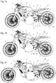
Figs. 1a, 1b, 1c show, in an axonometric view, a motorcycle with multi-configuration chassis according to the invention, illustrated in three different configurations of the countless configurations in which the motorcycle can be configured; -
Fig. 2 shows, in a partially sectioned axonometric view, the multi-configuration chassis complete with rigid chassis assembly, front fork assembly, rear fork assembly and saddle assembly; -
Fig. 3 shows, in a partially sectioned axonometric view, only the rigid chassis; -
Fig. 4 shows, in a partially sectioned transparent side view, the multi-configuration chassis complete with transmission assembly and rear wheel; -
Fig. 5 shows, in partially sectioned transparent side view, the system for adjusting the front fork assembly; -
Fig. 6 shows a diagram of the kinematic mechanism structure of the system for adjusting the front fork assembly; -
Fig. 7 shows, in a partially sectioned transparent side view, the system for adjusting the rear fork assembly and the saddle assembly; -
Fig. 8 shows a diagram of the kinematic structure of the system for adjusting the rear fork assembly and the saddle assembly; -
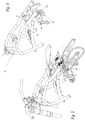
Figs. 9, 10 and 11 represent, respectively in a partially sectioned perspective view, in a top plan view and in a section along the line XI-XI ofFig. 10 , the system for adjusting the length of the front forks. - With reference to the details of the figures, a motorcycle with multi-configuration chassis comprises:
- a rigid chassis assembly Z6 for supporting the engine and the auxiliary fuel feed and mechanical devices;
- a rear fork assembly D;
- a front fork assembly Z1;
- a saddle assembly A4.
- With reference to
Figs. 2, 3 and4 , the engine of the motorcycle is connected to the rigid chassis Z6 in the points M2, M3 and M7. The output pinion M1 of the engine transmits motion to the double pinion A2 by means of the chain A1. The double pinion rotates mounted on a shaft in the point E, the shaft is housed on bushings fixed in the points M8 in the rigid chassis and in the points M9 in the rear fork D. The seats M8 and M9 are concentric to the point E. By means of the chain A3 the double pinion transmits motion to the wheel rotatable with axle in the point D1. -
Figs. 5, 6, 7 and 8 schematically show the front fork, rear fork and saddle assemblies, and the structural diagrams of their kinematic mechanisms for adjustment. - With reference to
Figs. 5 and 6 , the tilt of the fork F1 of the front wheel is implemented by means of varying the length of the rod Q connected to the chassis by means of the hinge P. - The rod Q can either be a hydraulic or electric cylinder or any other linear actuating means that allows the rod Q to extend or retract. The rod with variable length Q is connected to the rigid body V for supporting the forks by means of the connection V3.
- Rotation of the body V around the fulcrum R, connected to the rigid chassis, allows rotation of the forks. The body V, by means of the bearings V1 and V2, acts both as axial and radial support for the front fork assembly F1 and handlebar mounting Z1, better represented in
Figs. 9, 10 and 11 . - The body V, in jargon "steering head", is anchored to the forks and to the handlebar mounting through the plates Z2 and Z3 represented in
Fig. 9 . - With reference to
Figs. 5 ,9 and 10 , there is depicted the pin Z4 that connects the body V to the fork F1-fork plate Z2, Z3 and handlebar mounting Z1 assembly. - With reference to
Fig. 11 , the front forks are adjustable in length. The cylinder Z7 incorporates a shock absorber formed by the cylinder Z8, by the stem Z9 and by the spring Z10. - By feeding oil into the cylinder Z7, in the case in which the system is hydraulic, the cylinder Z8 moves and the whole of the hydraulic shock absorbing system moves as a consequence.
- The actuator that moves the shock absorber can be a hydraulic cylinder, such as the component Z9, or can be electric, or implemented with any other linear system of known type.
- The rear fork assembly D illustrated in
Fig. 8 is connected to the rigid chassis assembly by means of the points M and E. - The rear fork indicated with the letter D is hinged to the rigid chassis assembly in the fulcrum E. The fork, schematized as rigid body, rotates around the point E by means of the rod with variable length indicated with the letter A. The fork D is hinged to the rod A by means of the hinge B. The rod A, variable in length, is a hydraulic cylinder (variable rod) that can also be an electric cylinder or an automatic linear guide, according to the manufacturer's needs.
- The extension or retraction of the rod A allows rotation of the fork D, which determines an increase or decrease of the pitch of the motorcycle and/or a decrease or lowering of the height of the saddle from the ground, this latter also being adjustable by varying the configuration of the front forks.
- The rod A, which for simplicity is identified with the name of the cylinder, is connected to the rigid body N by means of the hinge O.
- The rigid body N is hinged to the rigid chassis assembly by means of the point M. The rigid body N, by means of the hinge H, is connected to the rod with variable length indicated with the letter F.
- The rod with variable length F is the rear shock absorber of the motorcycle. The shock absorber is connected to the rigid body which is the fork D, by means of the hinge M5.
- The shock absorber F exerts a resistant moment around the fulcrum E through to the arm M6 of the fork D. Once the travel of the cylinder A has been blocked, the kinematic mechanism allows the wheel to move so as to compress the shock absorber F.
- The kinematic mechanism also works if the positions of the cylinder A and the shock absorber F are inverted, so that the cylinder A takes the position of the shock absorber F and vice versa.
- The substantial difference lies in the operation of the shock absorber, which in the configuration indicated in
Figs. 7 and 8 , is a shock absorber that works in compression, i.e., it is compressed, while with the second construction method, which can in any case be implemented with the same kinematic mechanism, it works in traction, i.e., it is extended. - Adjustment of the tilt of the saddle assembly A4 is reproduced in
Figs. 5 and 6 . - The saddle A4 rotates around the fulcrum M, connected to the rigid chassis Z6, as illustrated in
Figs. 4 ,7 and 8 , through the rod with variable length I, which can be a cylinder or a variable linear element. - The rod I is hinged in the point C connected to the rigid chassis and in the point I1 connected to the saddle A4.
Claims (1)
- Motorcycle with multi-configuration chassis comprising:- a rigid chassis assembly (Z6) for supporting the engine and the auxiliary fuel feed and mechanical devices;- a rear fork assembly;- a front fork assembly;- a saddle assembly,wherein said multi-configuration chassis comprises hydraulic or electric cylinders adapted to modify their length to allow three adjustments selected from the following: rear fork assembly lengthening, , front fork assembly lengthening, saddle assembly tilt, andsaid front fork assembly comprises a hydraulic or electric cylinder (Z7) incorporating in a sliding manner a shock absorber consisting of a cylinder (Z8), of a stem (Z9) and of a spring (Z10); said saddle assembly comprises:-a saddle (A4) connected to the rigid chassis by means of a hinge with fulcrum (M);- a rod with variable length (I) comprising a hydraulic or electric cylinder having a first end connected to the rigid chassis assembly (Z6) by means of a hinge (C) and a second end connected to the saddle (A4) by means of a hinge connection (11), andcharacterized in that said hydraulic or electric cylinders are adapted to change their length to allow also a fourth type of adjustment by means of a front fork assembly tilt,wherein:said rear fork assembly comprises:- a rigid fork (D) hinged to the rigid chassis assembly (Z6) in a fulcrum (E);- a rod with variable length comprising a hydraulic or electric cylinder having a first end connected to the fork (D) by means of a hinge (B) and a second end connected to a rigid body (N) by means of a hinge connection (O);- a rigid body (N) rotatingly connected to the rigid chassis assembly (Z6) by means of a hinge (M);- a rod with variable length (F) forming the rear shock absorber of the motorcycle having a first end connected to the rigid fork (D) by means of a hinge (M5) and an arm (M6) and a second end connected to the rigid body (N) by means of a hinge connection (H);said front fork assembly comprises a rigid support body (V), connected to said rigid chassis assembly (Z6) by means of a pivot (R), and a hydraulic or electric cylinder (Q) comprising a first end connected to the rigid chassis assembly (Z6) by means of a hinge (P) and a second end connected to said rigid support body (V) of the front fork assembly by means of a hinge connection (V3).
Applications Claiming Priority (2)
| Application Number | Priority Date | Filing Date | Title |
|---|---|---|---|
| ITUA2015A001269A ITUA20151269A1 (en) | 2015-12-31 | 2015-12-31 | Motorcycle with multi-configuration frame |
| PCT/IT2016/000309 WO2017115393A2 (en) | 2015-12-31 | 2016-12-27 | Motorcycle with multi-configuration chassis |
Publications (2)
| Publication Number | Publication Date |
|---|---|
| EP3397550A2 EP3397550A2 (en) | 2018-11-07 |
| EP3397550B1 true EP3397550B1 (en) | 2021-09-22 |
Family
ID=57750313
Family Applications (1)
| Application Number | Title | Priority Date | Filing Date |
|---|---|---|---|
| EP16849916.8A Active EP3397550B1 (en) | 2015-12-31 | 2016-12-27 | Motorcycle with multi-configuration chassis |
Country Status (4)
| Country | Link |
|---|---|
| US (1) | US20210221465A1 (en) |
| EP (1) | EP3397550B1 (en) |
| IT (1) | ITUA20151269A1 (en) |
| WO (1) | WO2017115393A2 (en) |
Families Citing this family (2)
| Publication number | Priority date | Publication date | Assignee | Title |
|---|---|---|---|---|
| ES2784917B2 (en) * | 2020-07-03 | 2021-09-17 | Carmona Gutierrez Jose Antonio | Steering system for motorcycles |
| IT202100008522A1 (en) * | 2021-04-06 | 2022-10-06 | Umbria Kinetics Srl | OSCILLATION SYSTEM OF THE SWINGARM OF A WHEEL WITH RESPECT TO THE FRAME OF A VEHICLE. |
Family Cites Families (8)
| Publication number | Priority date | Publication date | Assignee | Title |
|---|---|---|---|---|
| DE3029373C2 (en) * | 1980-07-31 | 1985-05-02 | Jürgen 1000 Berlin Binder | Racing motorcycle |
| JPS6018476A (en) * | 1983-07-12 | 1985-01-30 | ヤマハ発動機株式会社 | Regulator for car height of motorcycle |
| JPH0662108B2 (en) * | 1984-05-07 | 1994-08-17 | ヤマハ発動機株式会社 | Attitude control device for vehicles such as motorcycles |
| JPH0822680B2 (en) * | 1985-04-11 | 1996-03-06 | ヤマハ発動機株式会社 | Vehicle height adjustment device |
| ES2049930T3 (en) * | 1989-10-26 | 1994-05-01 | Suzuki Co Ltd | MOTORCYCLE WITH BODY HEIGHT ADJUSTMENT MECHANISM. |
| US6899193B1 (en) * | 2004-02-20 | 2005-05-31 | Kevin J. Anibas | Motorcycle lateral suspension mechanism |
| JP4482442B2 (en) * | 2004-12-27 | 2010-06-16 | ヤマハ発動機株式会社 | vehicle |
| AT507383B1 (en) * | 2009-01-07 | 2010-12-15 | Ernst Dipl Ing Zimmer | MOTORCYCLE WITH HIGH RIDER SEAT POSITION |
-
2015
- 2015-12-31 IT ITUA2015A001269A patent/ITUA20151269A1/en unknown
-
2016
- 2016-12-27 US US16/066,918 patent/US20210221465A1/en not_active Abandoned
- 2016-12-27 EP EP16849916.8A patent/EP3397550B1/en active Active
- 2016-12-27 WO PCT/IT2016/000309 patent/WO2017115393A2/en not_active Ceased
Also Published As
| Publication number | Publication date |
|---|---|
| WO2017115393A2 (en) | 2017-07-06 |
| ITUA20151269A1 (en) | 2017-07-01 |
| EP3397550A2 (en) | 2018-11-07 |
| US20210221465A1 (en) | 2021-07-22 |
| WO2017115393A3 (en) | 2017-09-14 |
Similar Documents
| Publication | Publication Date | Title |
|---|---|---|
| EP3481708B1 (en) | Vehicle having three or more tilting wheels with reactive constraint suspension | |
| US5335929A (en) | Bicycle frame | |
| KR100489771B1 (en) | Swing arm type suspension system for vehicle | |
| US5599034A (en) | Single arm bicycle suspension fork | |
| US8827295B2 (en) | Front end device for a vehicle with a single steered front wheel and vehicle equipped with such a front end device | |
| US6823958B2 (en) | Progressive suspension device for the rear wheel of a motorcycle | |
| WO2013192622A1 (en) | Bicycle rear suspension with a two axis wheel path | |
| DE102007043121A1 (en) | Twist-beam axle with elastically suspended wheel carrier | |
| EP2202140B1 (en) | Stroke distance sensor system | |
| WO2009108112A1 (en) | Steering linkage | |
| CN105459747B (en) | A kind of FSC racing car lever push arm formula double cross arm independent suspension | |
| US6899193B1 (en) | Motorcycle lateral suspension mechanism | |
| WO2017115393A2 (en) | Motorcycle with multi-configuration chassis | |
| US20200102038A1 (en) | Leaning vehicle | |
| DE102016118272A1 (en) | SADDLE TYPE VEHICLE | |
| IT201900005556A1 (en) | ROLLANTE MOTORCYCLE WITH ROLLIO BLOCK DEVICE | |
| DE202014100624U1 (en) | Front suspension of a vehicle | |
| DE102013203188A1 (en) | Steering actuator assembly between the rear wheels of a two-lane vehicle | |
| CA3184148A1 (en) | Variable-geometry bicycle frame and method for dynamic changes to the geometry of a bicycle frame | |
| JPH03503624A (en) | cycle | |
| JP2024504415A5 (en) | ||
| US5720491A (en) | Light-weight cycle suspension | |
| DE4108905A1 (en) | Adaptive wheel suspension system for bicycle - has control processor receiving monitored data to adjust damping characteristics | |
| JP4559047B2 (en) | Vehicle swing arm suspension system | |
| DE102017109823A1 (en) | vehicle |
Legal Events
| Date | Code | Title | Description |
|---|---|---|---|
| STAA | Information on the status of an ep patent application or granted ep patent |
Free format text: STATUS: UNKNOWN |
|
| STAA | Information on the status of an ep patent application or granted ep patent |
Free format text: STATUS: THE INTERNATIONAL PUBLICATION HAS BEEN MADE |
|
| PUAI | Public reference made under article 153(3) epc to a published international application that has entered the european phase |
Free format text: ORIGINAL CODE: 0009012 |
|
| STAA | Information on the status of an ep patent application or granted ep patent |
Free format text: STATUS: REQUEST FOR EXAMINATION WAS MADE |
|
| 17P | Request for examination filed |
Effective date: 20180717 |
|
| AK | Designated contracting states |
Kind code of ref document: A2 Designated state(s): AL AT BE BG CH CY CZ DE DK EE ES FI FR GB GR HR HU IE IS IT LI LT LU LV MC MK MT NL NO PL PT RO RS SE SI SK SM TR |
|
| AX | Request for extension of the european patent |
Extension state: BA ME |
|
| DAV | Request for validation of the european patent (deleted) | ||
| DAX | Request for extension of the european patent (deleted) | ||
| STAA | Information on the status of an ep patent application or granted ep patent |
Free format text: STATUS: EXAMINATION IS IN PROGRESS |
|
| 17Q | First examination report despatched |
Effective date: 20200107 |
|
| GRAP | Despatch of communication of intention to grant a patent |
Free format text: ORIGINAL CODE: EPIDOSNIGR1 |
|
| STAA | Information on the status of an ep patent application or granted ep patent |
Free format text: STATUS: GRANT OF PATENT IS INTENDED |
|
| INTG | Intention to grant announced |
Effective date: 20210422 |
|
| GRAS | Grant fee paid |
Free format text: ORIGINAL CODE: EPIDOSNIGR3 |
|
| GRAA | (expected) grant |
Free format text: ORIGINAL CODE: 0009210 |
|
| STAA | Information on the status of an ep patent application or granted ep patent |
Free format text: STATUS: THE PATENT HAS BEEN GRANTED |
|
| AK | Designated contracting states |
Kind code of ref document: B1 Designated state(s): AL AT BE BG CH CY CZ DE DK EE ES FI FR GB GR HR HU IE IS IT LI LT LU LV MC MK MT NL NO PL PT RO RS SE SI SK SM TR |
|
| REG | Reference to a national code |
Ref country code: GB Ref legal event code: FG4D |
|
| REG | Reference to a national code |
Ref country code: DE Ref legal event code: R096 Ref document number: 602016064122 Country of ref document: DE |
|
| REG | Reference to a national code |
Ref country code: IE Ref legal event code: FG4D |
|
| REG | Reference to a national code |
Ref country code: CH Ref legal event code: EP Ref country code: AT Ref legal event code: REF Ref document number: 1432138 Country of ref document: AT Kind code of ref document: T Effective date: 20211015 |
|
| REG | Reference to a national code |
Ref country code: LT Ref legal event code: MG9D |
|
| REG | Reference to a national code |
Ref country code: NL Ref legal event code: MP Effective date: 20210922 |
|
| PG25 | Lapsed in a contracting state [announced via postgrant information from national office to epo] |
Ref country code: LT Free format text: LAPSE BECAUSE OF FAILURE TO SUBMIT A TRANSLATION OF THE DESCRIPTION OR TO PAY THE FEE WITHIN THE PRESCRIBED TIME-LIMIT Effective date: 20210922 Ref country code: BG Free format text: LAPSE BECAUSE OF FAILURE TO SUBMIT A TRANSLATION OF THE DESCRIPTION OR TO PAY THE FEE WITHIN THE PRESCRIBED TIME-LIMIT Effective date: 20211222 Ref country code: NO Free format text: LAPSE BECAUSE OF FAILURE TO SUBMIT A TRANSLATION OF THE DESCRIPTION OR TO PAY THE FEE WITHIN THE PRESCRIBED TIME-LIMIT Effective date: 20211222 Ref country code: HR Free format text: LAPSE BECAUSE OF FAILURE TO SUBMIT A TRANSLATION OF THE DESCRIPTION OR TO PAY THE FEE WITHIN THE PRESCRIBED TIME-LIMIT Effective date: 20210922 Ref country code: FI Free format text: LAPSE BECAUSE OF FAILURE TO SUBMIT A TRANSLATION OF THE DESCRIPTION OR TO PAY THE FEE WITHIN THE PRESCRIBED TIME-LIMIT Effective date: 20210922 Ref country code: RS Free format text: LAPSE BECAUSE OF FAILURE TO SUBMIT A TRANSLATION OF THE DESCRIPTION OR TO PAY THE FEE WITHIN THE PRESCRIBED TIME-LIMIT Effective date: 20210922 Ref country code: SE Free format text: LAPSE BECAUSE OF FAILURE TO SUBMIT A TRANSLATION OF THE DESCRIPTION OR TO PAY THE FEE WITHIN THE PRESCRIBED TIME-LIMIT Effective date: 20210922 |
|
| REG | Reference to a national code |
Ref country code: AT Ref legal event code: MK05 Ref document number: 1432138 Country of ref document: AT Kind code of ref document: T Effective date: 20210922 |
|
| PG25 | Lapsed in a contracting state [announced via postgrant information from national office to epo] |
Ref country code: LV Free format text: LAPSE BECAUSE OF FAILURE TO SUBMIT A TRANSLATION OF THE DESCRIPTION OR TO PAY THE FEE WITHIN THE PRESCRIBED TIME-LIMIT Effective date: 20210922 Ref country code: GR Free format text: LAPSE BECAUSE OF FAILURE TO SUBMIT A TRANSLATION OF THE DESCRIPTION OR TO PAY THE FEE WITHIN THE PRESCRIBED TIME-LIMIT Effective date: 20211223 |
|
| PG25 | Lapsed in a contracting state [announced via postgrant information from national office to epo] |
Ref country code: AT Free format text: LAPSE BECAUSE OF FAILURE TO SUBMIT A TRANSLATION OF THE DESCRIPTION OR TO PAY THE FEE WITHIN THE PRESCRIBED TIME-LIMIT Effective date: 20210922 |
|
| PG25 | Lapsed in a contracting state [announced via postgrant information from national office to epo] |
Ref country code: IS Free format text: LAPSE BECAUSE OF FAILURE TO SUBMIT A TRANSLATION OF THE DESCRIPTION OR TO PAY THE FEE WITHIN THE PRESCRIBED TIME-LIMIT Effective date: 20220122 Ref country code: SK Free format text: LAPSE BECAUSE OF FAILURE TO SUBMIT A TRANSLATION OF THE DESCRIPTION OR TO PAY THE FEE WITHIN THE PRESCRIBED TIME-LIMIT Effective date: 20210922 Ref country code: RO Free format text: LAPSE BECAUSE OF FAILURE TO SUBMIT A TRANSLATION OF THE DESCRIPTION OR TO PAY THE FEE WITHIN THE PRESCRIBED TIME-LIMIT Effective date: 20210922 Ref country code: PT Free format text: LAPSE BECAUSE OF FAILURE TO SUBMIT A TRANSLATION OF THE DESCRIPTION OR TO PAY THE FEE WITHIN THE PRESCRIBED TIME-LIMIT Effective date: 20220124 Ref country code: PL Free format text: LAPSE BECAUSE OF FAILURE TO SUBMIT A TRANSLATION OF THE DESCRIPTION OR TO PAY THE FEE WITHIN THE PRESCRIBED TIME-LIMIT Effective date: 20210922 Ref country code: NL Free format text: LAPSE BECAUSE OF FAILURE TO SUBMIT A TRANSLATION OF THE DESCRIPTION OR TO PAY THE FEE WITHIN THE PRESCRIBED TIME-LIMIT Effective date: 20210922 Ref country code: ES Free format text: LAPSE BECAUSE OF FAILURE TO SUBMIT A TRANSLATION OF THE DESCRIPTION OR TO PAY THE FEE WITHIN THE PRESCRIBED TIME-LIMIT Effective date: 20210922 Ref country code: EE Free format text: LAPSE BECAUSE OF FAILURE TO SUBMIT A TRANSLATION OF THE DESCRIPTION OR TO PAY THE FEE WITHIN THE PRESCRIBED TIME-LIMIT Effective date: 20210922 Ref country code: CZ Free format text: LAPSE BECAUSE OF FAILURE TO SUBMIT A TRANSLATION OF THE DESCRIPTION OR TO PAY THE FEE WITHIN THE PRESCRIBED TIME-LIMIT Effective date: 20210922 Ref country code: AL Free format text: LAPSE BECAUSE OF FAILURE TO SUBMIT A TRANSLATION OF THE DESCRIPTION OR TO PAY THE FEE WITHIN THE PRESCRIBED TIME-LIMIT Effective date: 20210922 |
|
| REG | Reference to a national code |
Ref country code: DE Ref legal event code: R097 Ref document number: 602016064122 Country of ref document: DE |
|
| PG25 | Lapsed in a contracting state [announced via postgrant information from national office to epo] |
Ref country code: MC Free format text: LAPSE BECAUSE OF FAILURE TO SUBMIT A TRANSLATION OF THE DESCRIPTION OR TO PAY THE FEE WITHIN THE PRESCRIBED TIME-LIMIT Effective date: 20210922 Ref country code: DK Free format text: LAPSE BECAUSE OF FAILURE TO SUBMIT A TRANSLATION OF THE DESCRIPTION OR TO PAY THE FEE WITHIN THE PRESCRIBED TIME-LIMIT Effective date: 20210922 |
|
| PLBE | No opposition filed within time limit |
Free format text: ORIGINAL CODE: 0009261 |
|
| REG | Reference to a national code |
Ref country code: CH Ref legal event code: PL |
|
| STAA | Information on the status of an ep patent application or granted ep patent |
Free format text: STATUS: NO OPPOSITION FILED WITHIN TIME LIMIT |
|
| 26N | No opposition filed |
Effective date: 20220623 |
|
| REG | Reference to a national code |
Ref country code: BE Ref legal event code: MM Effective date: 20211231 |
|
| PG25 | Lapsed in a contracting state [announced via postgrant information from national office to epo] |
Ref country code: LU Free format text: LAPSE BECAUSE OF NON-PAYMENT OF DUE FEES Effective date: 20211227 Ref country code: IE Free format text: LAPSE BECAUSE OF NON-PAYMENT OF DUE FEES Effective date: 20211227 |
|
| PG25 | Lapsed in a contracting state [announced via postgrant information from national office to epo] |
Ref country code: SI Free format text: LAPSE BECAUSE OF FAILURE TO SUBMIT A TRANSLATION OF THE DESCRIPTION OR TO PAY THE FEE WITHIN THE PRESCRIBED TIME-LIMIT Effective date: 20210922 Ref country code: FR Free format text: LAPSE BECAUSE OF NON-PAYMENT OF DUE FEES Effective date: 20211231 Ref country code: BE Free format text: LAPSE BECAUSE OF NON-PAYMENT OF DUE FEES Effective date: 20211231 |
|
| PG25 | Lapsed in a contracting state [announced via postgrant information from national office to epo] |
Ref country code: LI Free format text: LAPSE BECAUSE OF NON-PAYMENT OF DUE FEES Effective date: 20211231 Ref country code: CH Free format text: LAPSE BECAUSE OF NON-PAYMENT OF DUE FEES Effective date: 20211231 |
|
| PG25 | Lapsed in a contracting state [announced via postgrant information from national office to epo] |
Ref country code: IT Free format text: LAPSE BECAUSE OF FAILURE TO SUBMIT A TRANSLATION OF THE DESCRIPTION OR TO PAY THE FEE WITHIN THE PRESCRIBED TIME-LIMIT Effective date: 20210922 |
|
| PG25 | Lapsed in a contracting state [announced via postgrant information from national office to epo] |
Ref country code: CY Free format text: LAPSE BECAUSE OF FAILURE TO SUBMIT A TRANSLATION OF THE DESCRIPTION OR TO PAY THE FEE WITHIN THE PRESCRIBED TIME-LIMIT Effective date: 20210922 |
|
| PG25 | Lapsed in a contracting state [announced via postgrant information from national office to epo] |
Ref country code: SM Free format text: LAPSE BECAUSE OF FAILURE TO SUBMIT A TRANSLATION OF THE DESCRIPTION OR TO PAY THE FEE WITHIN THE PRESCRIBED TIME-LIMIT Effective date: 20210922 Ref country code: HU Free format text: LAPSE BECAUSE OF FAILURE TO SUBMIT A TRANSLATION OF THE DESCRIPTION OR TO PAY THE FEE WITHIN THE PRESCRIBED TIME-LIMIT; INVALID AB INITIO Effective date: 20161227 |
|
| P01 | Opt-out of the competence of the unified patent court (upc) registered |
Effective date: 20231211 |
|
| PG25 | Lapsed in a contracting state [announced via postgrant information from national office to epo] |
Ref country code: MK Free format text: LAPSE BECAUSE OF FAILURE TO SUBMIT A TRANSLATION OF THE DESCRIPTION OR TO PAY THE FEE WITHIN THE PRESCRIBED TIME-LIMIT Effective date: 20210922 |
|
| PG25 | Lapsed in a contracting state [announced via postgrant information from national office to epo] |
Ref country code: MT Free format text: LAPSE BECAUSE OF FAILURE TO SUBMIT A TRANSLATION OF THE DESCRIPTION OR TO PAY THE FEE WITHIN THE PRESCRIBED TIME-LIMIT Effective date: 20210922 |
|
| PGFP | Annual fee paid to national office [announced via postgrant information from national office to epo] |
Ref country code: DE Payment date: 20250529 Year of fee payment: 9 |
|
| PGFP | Annual fee paid to national office [announced via postgrant information from national office to epo] |
Ref country code: GB Payment date: 20250527 Year of fee payment: 9 |
|
| PG25 | Lapsed in a contracting state [announced via postgrant information from national office to epo] |
Ref country code: TR Free format text: LAPSE BECAUSE OF FAILURE TO SUBMIT A TRANSLATION OF THE DESCRIPTION OR TO PAY THE FEE WITHIN THE PRESCRIBED TIME-LIMIT Effective date: 20210922 |