EP3397355B1 - Sturzdetektionswarn-/-alarmvorrichtung und -verfahren - Google Patents
Sturzdetektionswarn-/-alarmvorrichtung und -verfahren Download PDFInfo
- Publication number
- EP3397355B1 EP3397355B1 EP16819753.1A EP16819753A EP3397355B1 EP 3397355 B1 EP3397355 B1 EP 3397355B1 EP 16819753 A EP16819753 A EP 16819753A EP 3397355 B1 EP3397355 B1 EP 3397355B1
- Authority
- EP
- European Patent Office
- Prior art keywords
- fall
- harness
- alert
- indicator
- state
- Prior art date
- Legal status (The legal status is an assumption and is not a legal conclusion. Google has not performed a legal analysis and makes no representation as to the accuracy of the status listed.)
- Active
Links
Images

Classifications
-
- G—PHYSICS
- G08—SIGNALLING
- G08B—SIGNALLING SYSTEMS, e.g. PERSONAL CALLING SYSTEMS; ORDER TELEGRAPHS; ALARM SYSTEMS
- G08B25/00—Alarm systems in which the location of the alarm condition is signalled to a central station, e.g. fire or police telegraphic systems
- G08B25/01—Alarm systems in which the location of the alarm condition is signalled to a central station, e.g. fire or police telegraphic systems characterised by the transmission medium
- G08B25/016—Personal emergency signalling and security systems
-
- A—HUMAN NECESSITIES
- A62—LIFE-SAVING; FIRE-FIGHTING
- A62B—DEVICES, APPARATUS OR METHODS FOR LIFE-SAVING
- A62B35/00—Safety belts or body harnesses; Similar equipment for limiting displacement of the human body, especially in case of sudden changes of motion
- A62B35/0006—Harnesses; Accessories therefor
- A62B35/0018—Full body harnesses covering at least shoulders and thighs
-
- A—HUMAN NECESSITIES
- A62—LIFE-SAVING; FIRE-FIGHTING
- A62B—DEVICES, APPARATUS OR METHODS FOR LIFE-SAVING
- A62B35/00—Safety belts or body harnesses; Similar equipment for limiting displacement of the human body, especially in case of sudden changes of motion
- A62B35/0006—Harnesses; Accessories therefor
- A62B35/0025—Details and accessories
-
- A—HUMAN NECESSITIES
- A62—LIFE-SAVING; FIRE-FIGHTING
- A62B—DEVICES, APPARATUS OR METHODS FOR LIFE-SAVING
- A62B35/00—Safety belts or body harnesses; Similar equipment for limiting displacement of the human body, especially in case of sudden changes of motion
- A62B35/04—Safety belts or body harnesses; Similar equipment for limiting displacement of the human body, especially in case of sudden changes of motion incorporating energy absorbing means
Definitions
- This disclosure relates to personal protective equipment (PPE) and more particularly to fall protection equipment (FPE), and even more particularly to fall indicators/fall detection devices as used in connection with fall harnesses and other fall protection equipment.
- PPE personal protective equipment
- FPE fall protection equipment
- Fall harnesses are an example of a critical piece of fall protection safety equipment that are integral to preventing accidents on the job site. They provide a reliable restraint system worn by the worker that is connected to a fixed anchor point on a supporting structure. Fall harnesses are designed to arrest the fall of a worker quickly and safely but result in the worker being suspended in the fall harness. If there is no ladder or scaffolding for the worker to climb back up, the worker will remain suspended until additional rescue help can be rendered. Being suspended in the fall harness for an extended period of time can lead to serious injury or death. Consequently, rapid response is critical.
- a fall indicator in a fall harness to provide notice that a fall harness has experienced a arrested fall while worn by worker, with the fall indicator being formed by a folded length of one of the straps that forms the fall harness that is secured in the folded condition by a breakable connection that breaks when the harness experiences an arrested fall while worn by a worker.
- fall indicators have a label or other indicia that is exposed when the breakable connection is broken and the folded length of strap unfolds, with the now exposed label or other indicia providing notice that the harness has experienced an arrested fall.
- US 2012/0050036 describes a harness for fall protection.
- US 2010/0231402 describes a personal fall protection monitoring system.
- US 2012/0228056 describes safety harnesses, connective ring attachments and back pads for use in safety harnesses.
- a fall detection/fall indicator device is provided that automatically senses when a user of fall protection equipment, such as a fall harness, has experienced an arrested fall and capable of providing an alarm/alert to other personnel so that they may provide assistance to the user in a timely fashion.
- a fall harness for use in fall protection.
- the fall harness includes a plurality of straps configured to attach the harness to a user and to other fall protection equipment.
- the harness further includes a fall indicator having a first state wherein the harness has not experienced an arrested fall, and a second state wherein the harness has experienced an arrested fall while worn by a user.
- the fall indicator includes a length of one of the straps, the length having a folded condition in the first state wherein the length is folded upon itself and maintained in the folded condition by a connection that breaks in response to the harness experiencing an arrested fall while worn by a user, and an unfolded condition in the second state wherein the connection is broken and the length unfolded in response to an arrested fall experienced by the harness while worn by a user.
- the fall indicator further includes an electrical connection having a pair of electrical contacts that are contacted together to form a closed circuit in the first state and that are spaced from each other in the second state to form an open circuit.
- the contacts are mounted on the length of strap so that the contacts face each other in adjacent portions of the length of strap in the folded condition and are contacted together to form the closed circuit, and so that the contacts are spaced from each other with the length of strap in the unfolded condition to form the open circuit.
- the fall indicator further includes an alert device operably connected to the electrical connection and responsive to the open circuit to provide an alert to other personnel that the fall indicator is in the second state after the harness experiences an arrested fall while worn by a user.
- the electrical connection includes a snap fastener having a post component defining one of the contacts, and a socket component defining the other contact and configured to releasably receive the post component.
- a processing unit is operably connected to the electrical connection to detect the open circuit and to the alarm device to initiate the alert in response to detection of the open circuit.
- the processing unit is a microprocessor unit.
- a housing mounts at least one of the processing unit and the alert device to the harness. In a further feature, the housing is fixed on the length of strap.
- the alert device is configured to emit an audible acoustic alert.
- the alert device includes a siren device.
- the alert device is configured to emit a visual alert.
- the alert device includes a strobe light device.
- the alert device is configured to emit a wireless signal that can be detected by a device remote from the harness to alert the device that the fall indicator is in the second state.
- the alert device includes a wireless transmitter.
- the harness includes at least one more fall indicator.
- a fall indicator for use on a piece of fall protection equipment to provide an alert to other personnel that a worker using or wearing the piece of fall protection equipment has experienced an arrested fall.
- the fall indicator has a first state wherein the piece of fall protection equipment has not experienced an arrested fall, and a second state wherein the harness has experienced an arrested fall while worn or used by a worker.
- the fall indicator includes a length of strap, the length having a folded condition in the first state wherein the length is folded upon itself and maintained in the folded condition by a connection that breaks in response to the piece of fall protection equipment experiencing an arrested fall, and an unfolded condition in the second state wherein the connection is broken and the length unfolded in response to an arrested fall.
- the fall indicator further includes an electrical connection having a pair of electrical contacts that are contacted together to form a closed circuit in the first date and that our spaced from each other in the second state to form an open circuit.
- the contacts are mounted on the length of strap so that the contacts face each other in adjacent portions of the length of strap in the folded condition and are contacted together to form the closed circuit, and so that the contacts are spaced from each other with the length of strap in the unfolded condition to form the open circuit.
- the fall indicator further includes an alert device operably connected to the electrical connection and responsive to the open circuit to provide an alert to other personnel that the fall indicator is in the second state after the piece of fall protection equipment experiences an arrested fall.
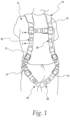
- an item of personal protective equipment (PPE) for providing fall protection is shown as a piece of fall protection equipment (FPE) in the form of a safety/fall harness 10 for use in fall protection.
- the safety harness includes a plurality of straps 12 configured to attach the harness 10 to a worker/user 14 and to other fall protection equipment, such as, for example, an anchor, a fall protection lanyard, or a self retracting lifeline.
- PPE personal protective equipment
- FPE fall protection equipment
- the safety harness includes a plurality of straps 12 configured to attach the harness 10 to a worker/user 14 and to other fall protection equipment, such as, for example, an anchor, a fall protection lanyard, or a self retracting lifeline.
- the harness depicted in Fig. 1 is for purposes of illustration and further specific details of the fall harness 10 will not be discussed herein except for those required for an understanding of the disclosed concepts, and that the appended claims are not limited to any specific details of a fall harness unless expressly recited in the claims.
- One or more fall protection/fall indicator devices 20 are provided at one or more corresponding key locations on the harness 10 where the harness 10 will experience a shock load when a user 14 of the harness 10 experiences an arrested fall.
- Each of the fall indicators 20 has a first state wherein the user 14 and the harness 10 have not experienced an arrested fall, and a second state wherein the user 14 and the harness 10 have experienced an arrested fall. In the second state, each of the fall indicators 20 provide an alarm/alert to other personnel that the user 14 has experienced an arrested fall, thereby enabling such personnel to provide assistance to the user 14 in a timely fashion.
- fall harnesses are well known and because they can be, and are, provided in a number of different configurations with different details that are compatible with the concepts of this disclosure, and further because the details of the safety harness 10 outside of the fall indicator 20 are not critical to understanding the fall indicator 20 and the method according to this disclosure, further details of the harness 10 outside of the fall indicator 20 will not be provided herein.
- Figs. 2A and 2B show the details of one of the fall indicators 20, and it should be understood that these details are consistent for all of the fall indicators 20 provided on the harness 10.
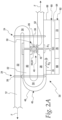
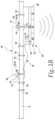
- the fall indicator 20 includes a length 22 of one of the straps 12, the length 22 having a folded condition in the first state shown in Fig. 2A wherein the length 22 is folded upon itself and maintained in the folded condition by a breakable or releasable connection 24 that breaks or releases in response to the harness 10 and the user 14 experiencing an arrested fall, and an unfolded condition in the second state shown in Fig. 2B wherein the connection 24 is broken and the length 22 unfolded in response to an arrested fall experienced by the harness 10 in the user 14.
- connection 24 is provided in the form of two spaced lines of stitching 26 that extend through and connect adjacent portions 28, 30, and 32 of the length 22 at folds 34 of the fall indicator 20 in the folded condition.
- proper selection of materials and stitch configuration will allow the lines of stitching 26 to break when the length 22 of strapping 12 experiences a predetermined tensile shock load F that corresponds to the expected load that will be experienced during an arrested fall.
- connection 24 in the form of the pair of spaced lines of stitching 26
- suitable forms of the connection 24 are contemplated within the scope of this disclosure, such as, for example, a single line of stitching, bonding agents or adhesive, and/or one or more breakable/releasable rivet connections.
- the fall indicator 20 includes an electrical connection 40 having a pair of electrical contacts 42 and 44 that are part of an electrical circuit, shown schematically at 45 in Figs. 2A and 2B .
- the electrical contacts 42 and 44 are connected together to form a closed circuit, shown schematically at 46 in Fig. 2A , in the first state and folded condition, and that are spaced from each other in the second state and unfolded condition to form an open circuit, shown schematically at 48 in Fig. 2B .
- the contacts 42 and 44 are mounted on the length 22 of strap 12 so that the contacts 42 and 44 face each other in adjacent portions 28 and 30 of the length 22 in the folded condition and are contacted together to form the closed circuit 46, as shown in Fig. 2A , and so that the contacts 42 and 44 will be spaced from each other to form the open circuit 48 when the length 22 of strap 12 is in the unfolded condition, as shown in Fig. 2B .
- the electrical connection 40 is provided in the form of an electrically conductive snap fastener 50 having an electrically conductive post component 52 defining one of the contacts 42 and an electrically conductive socket component 54 defining the other of the contacts 44 and configured to releasably receive a post 56 of the post component 52, with the engagement of the post 56 and the socket component 54 forming an electrically conductive connection.
- the post 56 in the illustrated embodiment of the snap fastener 50, includes a detent 57 that is movable past a detent 58 in the socket component 54 due to the resiliency of either the remainder of the post 56 or the remainder of the socket component 54.
- the fall indicator 20 further includes an electronics module 60 that at least includes an alert device 62 operably connected to the electrical connection 40 and responsive to the open circuit 48 to automatically provide an alert that the fall indicator 20 is in the second state after the harness 10 and the user 14 have experienced an arrested fall.
- an electronics module 60 that at least includes an alert device 62 operably connected to the electrical connection 40 and responsive to the open circuit 48 to automatically provide an alert that the fall indicator 20 is in the second state after the harness 10 and the user 14 have experienced an arrested fall.
- the electronics module 60 further includes a processing unit provided in the form of a microprocessor unit (MPU) 64 operably connected to the electrical connection 40 to automatically detect the open circuit 48 and operably connected to the alert device 62 to automatically initiate the alert in response to detection of the open circuit 48.
- MPU microprocessor unit
- the MPU 64 it will be desirable for the MPU 64 to be a very low power consumption MPU that is configured to wake up periodically to sense the condition of the fall indicator 20.
- the open circuit 48 is detected as a change in voltage at DI in the MPU 64 relative to the closed circuit 46 voltage at DI.
- a housing 66 is fixed on the length 22 of strap 12 and mounts and encloses the alert device 62 and the processing unit 64.
- the alert device 62 is configured to emit an audible acoustic alert/alarm that is detectable by personnel remote from the user 14. In some embodiments, the alert device 62 is configured to emit a visual alert that is detectable by personnel remote from the user 14. In some embodiments, the alert device 62 is configured to emit a wireless signal that can be detected by a device or devices (not shown) remote from the harness 10 and the user 14 to alert the remote device(s) that the fall indicator 20 is in the second state and that the user 14 has experienced an arrested fall.
- the remote device(s) may be in the form of one or more wireless phones (cell phones) that have a fall detection application software and that are carried by remote personnel, by a receiver that has an embedded acoustic alert device/generator, or/and a relay device that will relay the wireless signal to a cloud server or similar device configured to distribute the wireless signal, including the identification of the fallen user to the fallen user's supervisor and/or rescuers.
- the alert device 62 is configured to emit at least two of the visual alert, audible acoustic alert, and wireless signal.
- the alert device is configured to emit just one of the visual alert, audible acoustic alert, and wireless signal.
- the alert device 62 is configured to emit all three of the visual alert, audible acoustic alert, and wireless signal.
- the alert device 62 will include a siren device 68, of which many suitable types and configurations are known, with a high power siren device 68 capable of producing an 85 dB audible noise being desirable in many applications.
- the alert device 62 will include a strobe light device 70, of which many suitable types and configurations are known.
- the strobe light device 70 it will be desirable in some applications for the strobe light device 70 to be positioned so that it reflects of the material of the strap(s) 12 to further enhance the illumination.
- the alert device 62 will include a wireless transmitter 72, of which many suitable types and configurations are known.
- a method 74 for providing an alert that a fall harness 10 or other piece of fall protection equipment (FPE) 10 has experienced an arrested fall while worn or used by a user/worker 14.
- the method includes the step 76 of providing the piece of fall protection equipment 10 with an electrical circuit 45 that is closed in a first state wherein the piece of fall protection equipment 10 has not experienced an arrested fall, and that is open in a second state wherein the piece of fall protection equipment 10 has experienced an arrested fall while worn or used by a user 14.
- the method 74 further includes the step 78 of automatically initiating an alert in response to the open circuit.
- a method 80 for providing an alert that a fall harness 10 or other piece of fall protection equipment has experienced an arrested the fall when worn or used by a user 14, the piece of fall protection equipment 10 including a fall indicator 20 having a first state wherein the piece of fall protection equipment 10 has not experienced a fall, and a second state wherein the piece of fall protection equipment 10 has experienced a fall while worn or used by user 14.
- the method includes the steps of:
- the step 82 of electronically detecting includes creating 86 an open circuit 48 in response to the change of the fall indicator 20 from the first state to the second state.
- the electronics module 60 has been shown as being fixed to the fall indicator 20, the electronics module 60 could be fixed to other portions of the harness 10.
- the electronics module 60 has been shown as being mounted and enclosed in a single housing 66, the electronics module 60 could be mounted and enclosed in multiple housings.
- the illustrated embodiments show the alert device 62 as being connected to the electrical connection 40 via the MPU 64 and initiated by the MPU 64, other operable connections are contemplated that would initiate the alert device 62 in response to the open circuit 48.
- the illustrated embodiment of the electrical connection 40 is shown in the form of a snap fastener 50, other suitable forms of electrical connections having a pair of electrical contacts that can be connected in the first state and disconnected in the second state are contemplated within the scope of this disclosure.
- the fall indicator 20 has been disclosed herein in connection with a fall harness 10, use of the fall indicator 20 with other types of fall protection equipment, such as, for example, fall protection lanyards and SRL's, is contemplated within the scope of this disclosure.
- breakable/releasable connection 24 is shown the form of two lines of stitching 26 that extend through three layers of length 22 of strap 12, it is possible for either or both of the lines of stitching 26 to extend only through two layers of the length of strap 12, or for the connection to be a single line of stitching that extends only through two layers of the length of strap 12.
- US 2012/0050036 A1 teaches a safety harness that uses conductive webbing fibers to detect damage to the harness due to tearing of the webbing and the like, and teaches the use of circuitry and an alarm to alert the user to otherwise undetected damage to the harness, but does not teach or suggest a system or method for detecting when an arrested fall is experienced by a harness wearer.
- US 2010/0231402 A1 teaches a harness having tie-off hooks with integrated sensors that are configured to sense and communicate whether the harness wearer is properly tied off during use, e.g., at an elevated height, but does not teach or suggest a system or method for detecting when an arrested fall is experienced by the harness wearer.
- US 2012/0228056 A1 teaches a back pad system for a safety harness that includes a load indicator such as an area that visibly distends or tears when a wearer experiences a fall, but does not teach or suggest a system or method for detecting when an arrested fall is experienced by the harness wearer using a closed circuit formed by two electrical contacts mounted on a folded portion of a strap, the strap configured to unfold when a fall is experienced such that the two electrical contacts are spaced from each other and the circuit is opened, initiating an alert or alarm.
- a load indicator such as an area that visibly distends or tears when a wearer experiences a fall
Landscapes
- Business, Economics & Management (AREA)
- Emergency Management (AREA)
- Health & Medical Sciences (AREA)
- General Health & Medical Sciences (AREA)
- Engineering & Computer Science (AREA)
- Computer Security & Cryptography (AREA)
- Physics & Mathematics (AREA)
- General Physics & Mathematics (AREA)
- Emergency Lowering Means (AREA)
- Alarm Systems (AREA)
- Emergency Alarm Devices (AREA)
Claims (12)
- Fallanzeige (20) zur Verwendung auf einem Fallschutzausrüstungsteil, um einen Alarm für anderes Personal bereitzustellen, dass ein Arbeiter, der das Fallschutzausrüstungsteil verwendet oder trägt, Gegenstand eines gebremsten Falls war, wobei die Fallanzeige (20) einen ersten Status, in dem das Fallschutzausrüstungsteil nicht Gegenstand eines gebremsten Falls war, und einen zweiten Status aufweist, in dem das Fallschutzausrüstungsteil Gegenstand eines gebremsten Falls war, während es von einem Arbeiter getragen oder verwendet wurde, die Fallanzeige (20) umfassend:eine Länge (22) eines Riemens (12), wobei die Länge (22) einen gefalteten Zustand in dem ersten Status aufweist, wobei die Länge (22) auf sich selbst gefaltet und durch eine Verbindung (24) in dem gefalteten Zustand gehalten wird, die als Antwort darauf, dass das Fallschutzausrüstungsteil Gegenstand eines gebremsten Falls ist, bricht, und einen entfalteten Zustand in dem zweiten Status aufweist, in dem die Verbindung (24) gebrochen ist und die Länge (22) als Antwort auf einen gebremsten Fall entfaltet ist;eine elektrische Verbindung (40), die ein Paar elektrischer Kontakte (42, 44) aufweist, die in dem ersten Status miteinander in Kontakt gebracht sind, um einen geschlossenen Kreislauf (46) auszubilden, und die in dem zweiten Status voneinander beabstandet sind, um einen offenen Kreislauf (48) auszubilden, wobei die Kontakte (42, 44) an der Länge (22) des Riemens (12) angebracht sind, sodass die Kontakte (42, 44) in dem gefalteten Zustand einander in angrenzenden Abschnitten (28, 30) der Länge (22) des Riemens (12) zugewandt sind und miteinander in Kontakt gebracht sind, um den geschlossenen Kreislauf (46) auszubilden, und sodass die Kontakte (42, 44) voneinander beabstandet sind, wobei die Länge (22) des Riemens (12) in dem entfalteten Zustand ist, um den offenen Kreislauf (48) auszubilden; undeine Alarmvorrichtung (62), die betriebsfähig mit der elektrischen Verbindung (40) verbunden ist und auf den offenen Kreislauf (48) reaktionsfähig ist, um einen Alarm für anderes Personal bereitzustellen, dass die Fallanzeige (20) in dem zweiten Status ist, nachdem das Fallschutzausrüstungsteil Gegenstand eines gebremsten Falls war.
- Fallanzeige (20) nach Anspruch 1, wobei die Alarmvorrichtung (62) dazu konfiguriert ist, einen hörbaren akustischen Alarm zu emittieren.
- Fallanzeige (20) nach Anspruch 2, wobei die Alarmvorrichtung (62) eine Sirenenvorrichtung (68) umfasst.
- Fallanzeige (20) nach Anspruch 1, wobei die Alarmvorrichtung (62) dazu konfiguriert ist, einen visuellen Alarm zu emittieren.
- Fallanzeige (20) nach Anspruch 4, wobei die Alarmvorrichtung (62) eine Blinklichtvorrichtung (70) umfasst.
- Fallanzeige (20) nach Anspruch 1, wobei die Alarmvorrichtung (62) dazu konfiguriert ist, ein drahtloses Signal zu emittieren, das von einer von dem Gurtzeug (10) entfernten Vorrichtung detektiert werden kann, um die Vorrichtung zu alarmieren, dass die Fallanzeige (20) in dem zweiten Status ist.
- Fallanzeige (20) nach Anspruch 6, wobei die Alarmvorrichtung (62) einen drahtlosen Sender (72) umfasst.
- Fallgurtzeug (10) zur Verwendung im Fallschutz, das Fallgurtzeug (10) umfassend:eine Vielzahl von Riemen (12), die dazu konfiguriert sind, das Gurtzeug (10) an einem Benutzer (14) und an anderer Fallschutzausrüstung festzumachen; unddie Fallanzeige (20) nach Anspruch 1.
- Gurtzeug (10) nach Anspruch 8 oder Fallanzeige (20) nach Anspruch 1, wobei die elektrische Verbindung (40) einen Schnappverschluss (50) umfasst, der eine Stabkomponente (52), die einen der Kontakte (42, 44) definiert, und eine Buchsenkomponente (54) aufweist, die den anderen Kontakt definiert und dazu konfiguriert ist, die Stabkomponente (52) lösbar aufzunehmen.
- Gurtzeug (10) nach Anspruch 8, ferner umfassend:eine Verarbeitungseinheit (64), die betriebsfähig mit der elektrischen Verbindung (40) verbunden ist, um den offenen Kreislauf (48) zu detektieren, und mit der Alarmvorrichtung (62), um als Antwort auf die Detektion des offenen Kreislaufs (48) den Alarm auszulösen; undein Gehäuse (66), das mindestens eines aus der Verarbeitungseinheit (64) und der Alarmvorrichtung (62) an dem Gurtzeug (10) anbringt.
- Gurtzeug (10) nach Anspruch 10, wobei das Gehäuse (66) an der Länge (22) des Riemens (12) befestigt ist.
- Gurtzeug (10) nach Anspruch 8, ferner umfassend mindestens eine Fallanzeige (20) mehr.
Priority Applications (1)
| Application Number | Priority Date | Filing Date | Title |
|---|---|---|---|
| EP24209772.3A EP4477276A3 (de) | 2015-12-31 | 2016-12-01 | Sturzdetektionsalarm-/alarmvorrichtung und -verfahren |
Applications Claiming Priority (2)
| Application Number | Priority Date | Filing Date | Title |
|---|---|---|---|
| US201562273853P | 2015-12-31 | 2015-12-31 | |
| PCT/US2016/064332 WO2017116603A1 (en) | 2015-12-31 | 2016-12-01 | Fall detection alert/alarm device and method |
Related Child Applications (2)
| Application Number | Title | Priority Date | Filing Date |
|---|---|---|---|
| EP24209772.3A Division EP4477276A3 (de) | 2015-12-31 | 2016-12-01 | Sturzdetektionsalarm-/alarmvorrichtung und -verfahren |
| EP24209772.3A Division-Into EP4477276A3 (de) | 2015-12-31 | 2016-12-01 | Sturzdetektionsalarm-/alarmvorrichtung und -verfahren |
Publications (2)
| Publication Number | Publication Date |
|---|---|
| EP3397355A1 EP3397355A1 (de) | 2018-11-07 |
| EP3397355B1 true EP3397355B1 (de) | 2025-01-29 |
Family
ID=57680517
Family Applications (2)
| Application Number | Title | Priority Date | Filing Date |
|---|---|---|---|
| EP24209772.3A Pending EP4477276A3 (de) | 2015-12-31 | 2016-12-01 | Sturzdetektionsalarm-/alarmvorrichtung und -verfahren |
| EP16819753.1A Active EP3397355B1 (de) | 2015-12-31 | 2016-12-01 | Sturzdetektionswarn-/-alarmvorrichtung und -verfahren |
Family Applications Before (1)
| Application Number | Title | Priority Date | Filing Date |
|---|---|---|---|
| EP24209772.3A Pending EP4477276A3 (de) | 2015-12-31 | 2016-12-01 | Sturzdetektionsalarm-/alarmvorrichtung und -verfahren |
Country Status (4)
| Country | Link |
|---|---|
| US (4) | US10223898B2 (de) |
| EP (2) | EP4477276A3 (de) |
| CN (1) | CN108697911B (de) |
| WO (1) | WO2017116603A1 (de) |
Cited By (1)
| Publication number | Priority date | Publication date | Assignee | Title |
|---|---|---|---|---|
| US20240307717A1 (en) * | 2023-03-19 | 2024-09-19 | Paul Lingo | Personal Fall Arrest Assembly |
Families Citing this family (12)
| Publication number | Priority date | Publication date | Assignee | Title |
|---|---|---|---|---|
| WO2016094437A1 (en) * | 2014-12-08 | 2016-06-16 | Fire Innovations Llc | Firefighter multifunction ladder and escape belt |
| KR20190068583A (ko) * | 2016-10-14 | 2019-06-18 | 쓰리엠 이노베이티브 프로퍼티즈 캄파니 | 추락 방지 장치를 사용하여 에너지를 생성하기 위한 방법 및 기구 |
| US12412464B2 (en) | 2019-01-14 | 2025-09-09 | Msa Technology, Llc | Fall protection compliance system and method |
| US12429494B2 (en) | 2019-01-14 | 2025-09-30 | Msa Technology, Llc | Fall protection compliance system and method |
| EP4600928A3 (de) | 2019-01-14 | 2026-02-25 | MSA Technology, LLC | Sturzschutz-compliance-system und -verfahren |
| US20220088425A1 (en) * | 2019-02-19 | 2022-03-24 | 3M Innovative Properties Company | Systems and methods for monitoring the condition of a fall - protection safety system |
| US11247080B2 (en) * | 2019-10-10 | 2022-02-15 | Saudi Arabian Oil Company | Systems, methods, and apparatuses for ensuring worker safety |
| GB202001028D0 (en) * | 2020-01-24 | 2020-03-11 | Beacon Group Int Products Ltd | Fall arrest indicator |
| CN114034422B (zh) * | 2021-11-25 | 2024-09-06 | 安丹达工业技术(上海)有限公司 | 安全带坠落冲击指示装置 |
| WO2024018325A1 (en) * | 2022-07-20 | 2024-01-25 | 3M Innovative Properties Company | Composite connector comprising deformable section with interruptible signal-transmissive pathway |
| US12586963B2 (en) * | 2022-07-24 | 2026-03-24 | Lenovo (Singapore) Pte. Ltd | Electrical connector having an anomaly alert system and a brittle membrane |
| KR102870713B1 (ko) * | 2024-11-19 | 2025-10-16 | (주)디아이지엔지니어링건축사사무소 | 작업자 안전성과 작업성을 향상시킨 현장 조명벨트 |
Family Cites Families (18)
| Publication number | Priority date | Publication date | Assignee | Title |
|---|---|---|---|---|
| US3875450A (en) | 1973-02-26 | 1975-04-01 | Rca Corp | Cathode-ray tube with radiation-emitting index strip-like areas |
| JPH0947522A (ja) * | 1995-08-10 | 1997-02-18 | Takatsugu Oizumi | 安全ベルト |
| US8061479B2 (en) * | 2004-04-06 | 2011-11-22 | Harris Jr Rano J | Fall protection system |
| AU2006207863B2 (en) * | 2006-02-21 | 2009-05-07 | Fall Alert Industries Pty Ltd | Fall notifying apparatus |
| AU2007292897B2 (en) * | 2006-09-08 | 2012-04-26 | Honeywell Safety Products Usa, Inc. | Safety harnesses, connective ring attachments for use in safety harnesses and back pads for use in safety harnesses |
| US8292028B2 (en) * | 2006-09-11 | 2012-10-23 | Tech Safety Lines, Inc. | Fall arrest lanyard |
| JP2008259866A (ja) * | 2008-04-17 | 2008-10-30 | Takatsugu Oizumi | 多機能安全ベルト |
| US8106864B2 (en) | 2008-10-10 | 2012-01-31 | Lg Display Co., Ltd. | Liquid crystal display device |
| US8325053B2 (en) * | 2009-03-10 | 2012-12-04 | JCJ Inc. | Personal fall protection monitoring system |
| JP5116815B2 (ja) * | 2009-10-20 | 2013-01-09 | 藤井電工株式会社 | 安全帯およびその使用状況確認システム |
| US8902074B2 (en) * | 2010-08-26 | 2014-12-02 | Honeywell International, Inc. | Harness for fall protection |
| JP5311426B2 (ja) * | 2011-12-27 | 2013-10-09 | ニチユ三菱フォークリフト株式会社 | ピッキングフォークリフトの安全装置 |
| CN103366504B (zh) * | 2013-06-26 | 2015-09-02 | 重庆工业设备安装集团有限公司 | 纵横双生命线防护报警系统 |
| CN204073176U (zh) * | 2014-08-07 | 2015-01-07 | 上海旭富实业有限公司 | 一种安全带的防坠落标 |
| CN204147453U (zh) * | 2014-10-28 | 2015-02-11 | 国核工程有限公司 | 一种坠落声光报警缓冲式安全带 |
| US20160150360A1 (en) * | 2014-11-22 | 2016-05-26 | Fearless Technology, LLC | Canopy tracking device for skydiving equipment |
| CN204582358U (zh) * | 2015-04-20 | 2015-08-26 | 国家电网公司 | 一种具有报警功能的悬挂安全带 |
| CN105126270A (zh) * | 2015-08-31 | 2015-12-09 | 国网山东桓台县供电公司 | 电力系统智能防坠落登杆塔保护装置及其安全登杆方法 |
-
2016
- 2016-12-01 WO PCT/US2016/064332 patent/WO2017116603A1/en not_active Ceased
- 2016-12-01 CN CN201680082848.0A patent/CN108697911B/zh active Active
- 2016-12-01 EP EP24209772.3A patent/EP4477276A3/de active Pending
- 2016-12-01 EP EP16819753.1A patent/EP3397355B1/de active Active
- 2016-12-01 US US16/067,441 patent/US10223898B2/en active Active
-
2019
- 2019-01-18 US US16/251,613 patent/US10431072B2/en active Active
- 2019-08-19 US US16/543,804 patent/US10650664B2/en active Active
-
2020
- 2020-04-10 US US16/845,941 patent/US11024153B2/en active Active
Cited By (2)
| Publication number | Priority date | Publication date | Assignee | Title |
|---|---|---|---|---|
| US20240307717A1 (en) * | 2023-03-19 | 2024-09-19 | Paul Lingo | Personal Fall Arrest Assembly |
| US12544606B2 (en) * | 2023-03-19 | 2026-02-10 | Paul Lingo | Personal fall arrest system with transmitting alert module |
Also Published As
| Publication number | Publication date |
|---|---|
| US20190012900A1 (en) | 2019-01-10 |
| US20190371159A1 (en) | 2019-12-05 |
| EP4477276A2 (de) | 2024-12-18 |
| US20200242915A1 (en) | 2020-07-30 |
| US11024153B2 (en) | 2021-06-01 |
| WO2017116603A1 (en) | 2017-07-06 |
| CN108697911A (zh) | 2018-10-23 |
| US20190156656A1 (en) | 2019-05-23 |
| US10431072B2 (en) | 2019-10-01 |
| EP3397355A1 (de) | 2018-11-07 |
| US10650664B2 (en) | 2020-05-12 |
| CN108697911B (zh) | 2021-06-29 |
| US10223898B2 (en) | 2019-03-05 |
| EP4477276A3 (de) | 2025-01-22 |
Similar Documents
| Publication | Publication Date | Title |
|---|---|---|
| US11024153B2 (en) | Fall detection alert/alarm device and method | |
| US8928482B2 (en) | Personal fall protection system monitoring | |
| EP3138610B1 (de) | Sicherheitsausrüstung | |
| US10729922B2 (en) | Fall protection radio frequency emergency beacon | |
| KR101803319B1 (ko) | 하네스형 안전대에 부착가능한 에어백 시스템 | |
| CN109310895B (zh) | 具有无线坠落指示器的承重坠落保护连接器 | |
| KR101969385B1 (ko) | 하네스형 안전대의 배낭형 에어백 시스템 | |
| TW201127441A (en) | Safety belt and system for checking a belt-wearing status | |
| WO2012158554A2 (en) | Fall safety apparatus and method | |
| EP3178527B1 (de) | Fallschutzgurt mit beschädigungsanzeige | |
| CN111315452A (zh) | 安全背带、包括安全背带的安全设备和保护方法 | |
| EP3199205B1 (de) | Fallschutzgurt mit beschädigungsanzeige | |
| EP3178528B1 (de) | Fallschutzgurt mit beschädigungsanzeige | |
| KR20170074523A (ko) | 고소작업용 안전벨트 | |
| CN214312029U (zh) | 一种防坠落系统 | |
| GB2596170A (en) | Fall arrest indicator | |
| KR20210050730A (ko) | 고소작업자 추락방지용 경보장치 | |
| US20130154825A1 (en) | Hazard/perimeter safety system | |
| CN112043018A (zh) | 一种坠落救援保护装置 | |
| CN110559570A (zh) | 感应装置、检测系统及安全挂钩 |
Legal Events
| Date | Code | Title | Description |
|---|---|---|---|
| STAA | Information on the status of an ep patent application or granted ep patent |
Free format text: STATUS: UNKNOWN |
|
| STAA | Information on the status of an ep patent application or granted ep patent |
Free format text: STATUS: THE INTERNATIONAL PUBLICATION HAS BEEN MADE |
|
| PUAI | Public reference made under article 153(3) epc to a published international application that has entered the european phase |
Free format text: ORIGINAL CODE: 0009012 |
|
| STAA | Information on the status of an ep patent application or granted ep patent |
Free format text: STATUS: REQUEST FOR EXAMINATION WAS MADE |
|
| 17P | Request for examination filed |
Effective date: 20180628 |
|
| AK | Designated contracting states |
Kind code of ref document: A1 Designated state(s): AL AT BE BG CH CY CZ DE DK EE ES FI FR GB GR HR HU IE IS IT LI LT LU LV MC MK MT NL NO PL PT RO RS SE SI SK SM TR |
|
| AX | Request for extension of the european patent |
Extension state: BA ME |
|
| DAV | Request for validation of the european patent (deleted) | ||
| DAX | Request for extension of the european patent (deleted) | ||
| STAA | Information on the status of an ep patent application or granted ep patent |
Free format text: STATUS: EXAMINATION IS IN PROGRESS |
|
| 17Q | First examination report despatched |
Effective date: 20211129 |
|
| GRAP | Despatch of communication of intention to grant a patent |
Free format text: ORIGINAL CODE: EPIDOSNIGR1 |
|
| STAA | Information on the status of an ep patent application or granted ep patent |
Free format text: STATUS: GRANT OF PATENT IS INTENDED |
|
| INTG | Intention to grant announced |
Effective date: 20240709 |
|
| GRAS | Grant fee paid |
Free format text: ORIGINAL CODE: EPIDOSNIGR3 |
|
| GRAA | (expected) grant |
Free format text: ORIGINAL CODE: 0009210 |
|
| STAA | Information on the status of an ep patent application or granted ep patent |
Free format text: STATUS: THE PATENT HAS BEEN GRANTED |
|
| AK | Designated contracting states |
Kind code of ref document: B1 Designated state(s): AL AT BE BG CH CY CZ DE DK EE ES FI FR GB GR HR HU IE IS IT LI LT LU LV MC MK MT NL NO PL PT RO RS SE SI SK SM TR |
|
| REG | Reference to a national code |
Ref country code: GB Ref legal event code: FG4D |
|
| REG | Reference to a national code |
Ref country code: CH Ref legal event code: EP |
|
| REG | Reference to a national code |
Ref country code: DE Ref legal event code: R096 Ref document number: 602016091104 Country of ref document: DE |
|
| REG | Reference to a national code |
Ref country code: IE Ref legal event code: FG4D |
|
| REG | Reference to a national code |
Ref country code: NL Ref legal event code: MP Effective date: 20250129 |
|
| RAP2 | Party data changed (patent owner data changed or rights of a patent transferred) |
Owner name: HONEYWELL SAFETY PRODUCTS USA, INC. |
|
| REG | Reference to a national code |
Ref country code: DE Ref legal event code: R081 Ref document number: 602016091104 Country of ref document: DE Owner name: HONEYWELL SAFETY PRODUCTS USA, INC., WILMINGTO, US Free format text: FORMER OWNER: HONEYWELL INTERNATIONAL INC., MORRIS PLAINS, NJ, US |
|
| PG25 | Lapsed in a contracting state [announced via postgrant information from national office to epo] |
Ref country code: NL Free format text: LAPSE BECAUSE OF FAILURE TO SUBMIT A TRANSLATION OF THE DESCRIPTION OR TO PAY THE FEE WITHIN THE PRESCRIBED TIME-LIMIT Effective date: 20250129 |
|
| PG25 | Lapsed in a contracting state [announced via postgrant information from national office to epo] |
Ref country code: RS Free format text: LAPSE BECAUSE OF FAILURE TO SUBMIT A TRANSLATION OF THE DESCRIPTION OR TO PAY THE FEE WITHIN THE PRESCRIBED TIME-LIMIT Effective date: 20250429 |
|
| PG25 | Lapsed in a contracting state [announced via postgrant information from national office to epo] |
Ref country code: FI Free format text: LAPSE BECAUSE OF FAILURE TO SUBMIT A TRANSLATION OF THE DESCRIPTION OR TO PAY THE FEE WITHIN THE PRESCRIBED TIME-LIMIT Effective date: 20250129 |
|
| PG25 | Lapsed in a contracting state [announced via postgrant information from national office to epo] |
Ref country code: PL Free format text: LAPSE BECAUSE OF FAILURE TO SUBMIT A TRANSLATION OF THE DESCRIPTION OR TO PAY THE FEE WITHIN THE PRESCRIBED TIME-LIMIT Effective date: 20250129 |
|
| PG25 | Lapsed in a contracting state [announced via postgrant information from national office to epo] |
Ref country code: ES Free format text: LAPSE BECAUSE OF FAILURE TO SUBMIT A TRANSLATION OF THE DESCRIPTION OR TO PAY THE FEE WITHIN THE PRESCRIBED TIME-LIMIT Effective date: 20250129 |
|
| REG | Reference to a national code |
Ref country code: LT Ref legal event code: MG9D |
|
| PG25 | Lapsed in a contracting state [announced via postgrant information from national office to epo] |
Ref country code: IS Free format text: LAPSE BECAUSE OF FAILURE TO SUBMIT A TRANSLATION OF THE DESCRIPTION OR TO PAY THE FEE WITHIN THE PRESCRIBED TIME-LIMIT Effective date: 20250529 Ref country code: NO Free format text: LAPSE BECAUSE OF FAILURE TO SUBMIT A TRANSLATION OF THE DESCRIPTION OR TO PAY THE FEE WITHIN THE PRESCRIBED TIME-LIMIT Effective date: 20250429 |
|
| REG | Reference to a national code |
Ref country code: AT Ref legal event code: MK05 Ref document number: 1762868 Country of ref document: AT Kind code of ref document: T Effective date: 20250129 |
|
| PG25 | Lapsed in a contracting state [announced via postgrant information from national office to epo] |
Ref country code: HR Free format text: LAPSE BECAUSE OF FAILURE TO SUBMIT A TRANSLATION OF THE DESCRIPTION OR TO PAY THE FEE WITHIN THE PRESCRIBED TIME-LIMIT Effective date: 20250129 |
|
| PG25 | Lapsed in a contracting state [announced via postgrant information from national office to epo] |
Ref country code: PT Free format text: LAPSE BECAUSE OF FAILURE TO SUBMIT A TRANSLATION OF THE DESCRIPTION OR TO PAY THE FEE WITHIN THE PRESCRIBED TIME-LIMIT Effective date: 20250529 Ref country code: LV Free format text: LAPSE BECAUSE OF FAILURE TO SUBMIT A TRANSLATION OF THE DESCRIPTION OR TO PAY THE FEE WITHIN THE PRESCRIBED TIME-LIMIT Effective date: 20250129 |
|
| PG25 | Lapsed in a contracting state [announced via postgrant information from national office to epo] |
Ref country code: BG Free format text: LAPSE BECAUSE OF FAILURE TO SUBMIT A TRANSLATION OF THE DESCRIPTION OR TO PAY THE FEE WITHIN THE PRESCRIBED TIME-LIMIT Effective date: 20250129 Ref country code: GR Free format text: LAPSE BECAUSE OF FAILURE TO SUBMIT A TRANSLATION OF THE DESCRIPTION OR TO PAY THE FEE WITHIN THE PRESCRIBED TIME-LIMIT Effective date: 20250430 |
|
| REG | Reference to a national code |
Ref country code: GB Ref legal event code: 732E Free format text: REGISTERED BETWEEN 20250626 AND 20250702 |
|
| PG25 | Lapsed in a contracting state [announced via postgrant information from national office to epo] |
Ref country code: AT Free format text: LAPSE BECAUSE OF FAILURE TO SUBMIT A TRANSLATION OF THE DESCRIPTION OR TO PAY THE FEE WITHIN THE PRESCRIBED TIME-LIMIT Effective date: 20250129 |
|
| PG25 | Lapsed in a contracting state [announced via postgrant information from national office to epo] |
Ref country code: SE Free format text: LAPSE BECAUSE OF FAILURE TO SUBMIT A TRANSLATION OF THE DESCRIPTION OR TO PAY THE FEE WITHIN THE PRESCRIBED TIME-LIMIT Effective date: 20250129 |
|
| PG25 | Lapsed in a contracting state [announced via postgrant information from national office to epo] |
Ref country code: SM Free format text: LAPSE BECAUSE OF FAILURE TO SUBMIT A TRANSLATION OF THE DESCRIPTION OR TO PAY THE FEE WITHIN THE PRESCRIBED TIME-LIMIT Effective date: 20250129 |
|
| PG25 | Lapsed in a contracting state [announced via postgrant information from national office to epo] |
Ref country code: DK Free format text: LAPSE BECAUSE OF FAILURE TO SUBMIT A TRANSLATION OF THE DESCRIPTION OR TO PAY THE FEE WITHIN THE PRESCRIBED TIME-LIMIT Effective date: 20250129 |
|
| PG25 | Lapsed in a contracting state [announced via postgrant information from national office to epo] |
Ref country code: IT Free format text: LAPSE BECAUSE OF FAILURE TO SUBMIT A TRANSLATION OF THE DESCRIPTION OR TO PAY THE FEE WITHIN THE PRESCRIBED TIME-LIMIT Effective date: 20250129 |
|
| PG25 | Lapsed in a contracting state [announced via postgrant information from national office to epo] |
Ref country code: EE Free format text: LAPSE BECAUSE OF FAILURE TO SUBMIT A TRANSLATION OF THE DESCRIPTION OR TO PAY THE FEE WITHIN THE PRESCRIBED TIME-LIMIT Effective date: 20250129 Ref country code: CZ Free format text: LAPSE BECAUSE OF FAILURE TO SUBMIT A TRANSLATION OF THE DESCRIPTION OR TO PAY THE FEE WITHIN THE PRESCRIBED TIME-LIMIT Effective date: 20250129 |
|
| PG25 | Lapsed in a contracting state [announced via postgrant information from national office to epo] |
Ref country code: RO Free format text: LAPSE BECAUSE OF FAILURE TO SUBMIT A TRANSLATION OF THE DESCRIPTION OR TO PAY THE FEE WITHIN THE PRESCRIBED TIME-LIMIT Effective date: 20250129 |
|
| PG25 | Lapsed in a contracting state [announced via postgrant information from national office to epo] |
Ref country code: SK Free format text: LAPSE BECAUSE OF FAILURE TO SUBMIT A TRANSLATION OF THE DESCRIPTION OR TO PAY THE FEE WITHIN THE PRESCRIBED TIME-LIMIT Effective date: 20250129 |
|
| REG | Reference to a national code |
Ref country code: DE Ref legal event code: R097 Ref document number: 602016091104 Country of ref document: DE |
|
| PLBE | No opposition filed within time limit |
Free format text: ORIGINAL CODE: 0009261 |
|
| STAA | Information on the status of an ep patent application or granted ep patent |
Free format text: STATUS: NO OPPOSITION FILED WITHIN TIME LIMIT |
|
| 26N | No opposition filed |
Effective date: 20251030 |
|
| PGFP | Annual fee paid to national office [announced via postgrant information from national office to epo] |
Ref country code: GB Payment date: 20251223 Year of fee payment: 10 |
|
| PGFP | Annual fee paid to national office [announced via postgrant information from national office to epo] |
Ref country code: FR Payment date: 20251223 Year of fee payment: 10 |
|
| PGFP | Annual fee paid to national office [announced via postgrant information from national office to epo] |
Ref country code: DE Payment date: 20251229 Year of fee payment: 10 |