EP3396764A1 - Fuel cell system and fuel cell system control method - Google Patents
Fuel cell system and fuel cell system control method Download PDFInfo
- Publication number
- EP3396764A1 EP3396764A1 EP16878284.5A EP16878284A EP3396764A1 EP 3396764 A1 EP3396764 A1 EP 3396764A1 EP 16878284 A EP16878284 A EP 16878284A EP 3396764 A1 EP3396764 A1 EP 3396764A1
- Authority
- EP
- European Patent Office
- Prior art keywords
- fuel cell
- fuel
- battery
- cell stack
- power
- Prior art date
- Legal status (The legal status is an assumption and is not a legal conclusion. Google has not performed a legal analysis and makes no representation as to the accuracy of the status listed.)
- Granted
Links
- 239000000446 fuel Substances 0.000 title claims abstract description 641
- 238000000034 method Methods 0.000 title claims abstract description 71
- 238000010248 power generation Methods 0.000 claims abstract description 126
- 239000007800 oxidant agent Substances 0.000 claims abstract description 13
- 230000001590 oxidative effect Effects 0.000 claims abstract description 13
- 230000007423 decrease Effects 0.000 claims description 38
- 230000003247 decreasing effect Effects 0.000 claims description 11
- 239000007789 gas Substances 0.000 description 141
- 238000007084 catalytic combustion reaction Methods 0.000 description 18
- 230000001681 protective effect Effects 0.000 description 17
- 230000002950 deficient Effects 0.000 description 16
- 238000009792 diffusion process Methods 0.000 description 14
- 239000000567 combustion gas Substances 0.000 description 12
- 238000004364 calculation method Methods 0.000 description 9
- 239000002828 fuel tank Substances 0.000 description 8
- 239000000203 mixture Substances 0.000 description 8
- 230000006866 deterioration Effects 0.000 description 7
- 230000007812 deficiency Effects 0.000 description 6
- 238000002474 experimental method Methods 0.000 description 5
- UFHFLCQGNIYNRP-UHFFFAOYSA-N Hydrogen Chemical compound [H][H] UFHFLCQGNIYNRP-UHFFFAOYSA-N 0.000 description 4
- 239000001257 hydrogen Substances 0.000 description 4
- 229910052739 hydrogen Inorganic materials 0.000 description 4
- 230000001172 regenerating effect Effects 0.000 description 4
- QVGXLLKOCUKJST-UHFFFAOYSA-N atomic oxygen Chemical compound [O] QVGXLLKOCUKJST-UHFFFAOYSA-N 0.000 description 3
- 238000010586 diagram Methods 0.000 description 3
- 238000003487 electrochemical reaction Methods 0.000 description 3
- 238000002347 injection Methods 0.000 description 3
- 239000007924 injection Substances 0.000 description 3
- 239000001301 oxygen Substances 0.000 description 3
- 229910052760 oxygen Inorganic materials 0.000 description 3
- 239000007787 solid Substances 0.000 description 3
- CURLTUGMZLYLDI-UHFFFAOYSA-N Carbon dioxide Chemical compound O=C=O CURLTUGMZLYLDI-UHFFFAOYSA-N 0.000 description 2
- LFQSCWFLJHTTHZ-UHFFFAOYSA-N Ethanol Chemical compound CCO LFQSCWFLJHTTHZ-UHFFFAOYSA-N 0.000 description 2
- 239000003054 catalyst Substances 0.000 description 2
- 238000006555 catalytic reaction Methods 0.000 description 2
- 239000007788 liquid Substances 0.000 description 2
- 238000004519 manufacturing process Methods 0.000 description 2
- 239000005518 polymer electrolyte Substances 0.000 description 2
- XLYOFNOQVPJJNP-UHFFFAOYSA-N water Substances O XLYOFNOQVPJJNP-UHFFFAOYSA-N 0.000 description 2
- HBBGRARXTFLTSG-UHFFFAOYSA-N Lithium ion Chemical compound [Li+] HBBGRARXTFLTSG-UHFFFAOYSA-N 0.000 description 1
- 229910002092 carbon dioxide Inorganic materials 0.000 description 1
- 239000001569 carbon dioxide Substances 0.000 description 1
- 239000000919 ceramic Substances 0.000 description 1
- 238000006243 chemical reaction Methods 0.000 description 1
- 238000002485 combustion reaction Methods 0.000 description 1
- 230000003111 delayed effect Effects 0.000 description 1
- 239000006185 dispersion Substances 0.000 description 1
- 239000003792 electrolyte Substances 0.000 description 1
- 239000002737 fuel gas Substances 0.000 description 1
- 230000020169 heat generation Effects 0.000 description 1
- 238000010438 heat treatment Methods 0.000 description 1
- 239000011261 inert gas Substances 0.000 description 1
- 230000010354 integration Effects 0.000 description 1
- 229910001416 lithium ion Inorganic materials 0.000 description 1
- VUZPPFZMUPKLLV-UHFFFAOYSA-N methane;hydrate Chemical compound C.O VUZPPFZMUPKLLV-UHFFFAOYSA-N 0.000 description 1
- 230000003647 oxidation Effects 0.000 description 1
- 238000007254 oxidation reaction Methods 0.000 description 1
- 230000002093 peripheral effect Effects 0.000 description 1
- 238000010926 purge Methods 0.000 description 1
- 238000003860 storage Methods 0.000 description 1
- 238000010792 warming Methods 0.000 description 1
Images


Classifications
-
- B—PERFORMING OPERATIONS; TRANSPORTING
- B60—VEHICLES IN GENERAL
- B60L—PROPULSION OF ELECTRICALLY-PROPELLED VEHICLES; SUPPLYING ELECTRIC POWER FOR AUXILIARY EQUIPMENT OF ELECTRICALLY-PROPELLED VEHICLES; ELECTRODYNAMIC BRAKE SYSTEMS FOR VEHICLES IN GENERAL; MAGNETIC SUSPENSION OR LEVITATION FOR VEHICLES; MONITORING OPERATING VARIABLES OF ELECTRICALLY-PROPELLED VEHICLES; ELECTRIC SAFETY DEVICES FOR ELECTRICALLY-PROPELLED VEHICLES
- B60L50/00—Electric propulsion with power supplied within the vehicle
- B60L50/50—Electric propulsion with power supplied within the vehicle using propulsion power supplied by batteries or fuel cells
- B60L50/70—Electric propulsion with power supplied within the vehicle using propulsion power supplied by batteries or fuel cells using power supplied by fuel cells
-
- B—PERFORMING OPERATIONS; TRANSPORTING
- B60—VEHICLES IN GENERAL
- B60L—PROPULSION OF ELECTRICALLY-PROPELLED VEHICLES; SUPPLYING ELECTRIC POWER FOR AUXILIARY EQUIPMENT OF ELECTRICALLY-PROPELLED VEHICLES; ELECTRODYNAMIC BRAKE SYSTEMS FOR VEHICLES IN GENERAL; MAGNETIC SUSPENSION OR LEVITATION FOR VEHICLES; MONITORING OPERATING VARIABLES OF ELECTRICALLY-PROPELLED VEHICLES; ELECTRIC SAFETY DEVICES FOR ELECTRICALLY-PROPELLED VEHICLES
- B60L58/00—Methods or circuit arrangements for monitoring or controlling batteries or fuel cells, specially adapted for electric vehicles
- B60L58/30—Methods or circuit arrangements for monitoring or controlling batteries or fuel cells, specially adapted for electric vehicles for monitoring or controlling fuel cells
- B60L58/32—Methods or circuit arrangements for monitoring or controlling batteries or fuel cells, specially adapted for electric vehicles for monitoring or controlling fuel cells for controlling the temperature of fuel cells, e.g. by controlling the electric load
- B60L58/34—Methods or circuit arrangements for monitoring or controlling batteries or fuel cells, specially adapted for electric vehicles for monitoring or controlling fuel cells for controlling the temperature of fuel cells, e.g. by controlling the electric load by heating
-
- H—ELECTRICITY
- H01—ELECTRIC ELEMENTS
- H01M—PROCESSES OR MEANS, e.g. BATTERIES, FOR THE DIRECT CONVERSION OF CHEMICAL ENERGY INTO ELECTRICAL ENERGY
- H01M16/00—Structural combinations of different types of electrochemical generators
- H01M16/003—Structural combinations of different types of electrochemical generators of fuel cells with other electrochemical devices, e.g. capacitors, electrolysers
- H01M16/006—Structural combinations of different types of electrochemical generators of fuel cells with other electrochemical devices, e.g. capacitors, electrolysers of fuel cells with rechargeable batteries
-
- H—ELECTRICITY
- H01—ELECTRIC ELEMENTS
- H01M—PROCESSES OR MEANS, e.g. BATTERIES, FOR THE DIRECT CONVERSION OF CHEMICAL ENERGY INTO ELECTRICAL ENERGY
- H01M8/00—Fuel cells; Manufacture thereof
- H01M8/04—Auxiliary arrangements, e.g. for control of pressure or for circulation of fluids
- H01M8/04082—Arrangements for control of reactant parameters, e.g. pressure or concentration
- H01M8/04201—Reactant storage and supply, e.g. means for feeding, pipes
-
- H—ELECTRICITY
- H01—ELECTRIC ELEMENTS
- H01M—PROCESSES OR MEANS, e.g. BATTERIES, FOR THE DIRECT CONVERSION OF CHEMICAL ENERGY INTO ELECTRICAL ENERGY
- H01M8/00—Fuel cells; Manufacture thereof
- H01M8/04—Auxiliary arrangements, e.g. for control of pressure or for circulation of fluids
- H01M8/04223—Auxiliary arrangements, e.g. for control of pressure or for circulation of fluids during start-up or shut-down; Depolarisation or activation, e.g. purging; Means for short-circuiting defective fuel cells
- H01M8/04225—Auxiliary arrangements, e.g. for control of pressure or for circulation of fluids during start-up or shut-down; Depolarisation or activation, e.g. purging; Means for short-circuiting defective fuel cells during start-up
-
- H—ELECTRICITY
- H01—ELECTRIC ELEMENTS
- H01M—PROCESSES OR MEANS, e.g. BATTERIES, FOR THE DIRECT CONVERSION OF CHEMICAL ENERGY INTO ELECTRICAL ENERGY
- H01M8/00—Fuel cells; Manufacture thereof
- H01M8/04—Auxiliary arrangements, e.g. for control of pressure or for circulation of fluids
- H01M8/04223—Auxiliary arrangements, e.g. for control of pressure or for circulation of fluids during start-up or shut-down; Depolarisation or activation, e.g. purging; Means for short-circuiting defective fuel cells
- H01M8/04228—Auxiliary arrangements, e.g. for control of pressure or for circulation of fluids during start-up or shut-down; Depolarisation or activation, e.g. purging; Means for short-circuiting defective fuel cells during shut-down
-
- H—ELECTRICITY
- H01—ELECTRIC ELEMENTS
- H01M—PROCESSES OR MEANS, e.g. BATTERIES, FOR THE DIRECT CONVERSION OF CHEMICAL ENERGY INTO ELECTRICAL ENERGY
- H01M8/00—Fuel cells; Manufacture thereof
- H01M8/04—Auxiliary arrangements, e.g. for control of pressure or for circulation of fluids
- H01M8/04223—Auxiliary arrangements, e.g. for control of pressure or for circulation of fluids during start-up or shut-down; Depolarisation or activation, e.g. purging; Means for short-circuiting defective fuel cells
- H01M8/04268—Heating of fuel cells during the start-up of the fuel cells
-
- H—ELECTRICITY
- H01—ELECTRIC ELEMENTS
- H01M—PROCESSES OR MEANS, e.g. BATTERIES, FOR THE DIRECT CONVERSION OF CHEMICAL ENERGY INTO ELECTRICAL ENERGY
- H01M8/00—Fuel cells; Manufacture thereof
- H01M8/04—Auxiliary arrangements, e.g. for control of pressure or for circulation of fluids
- H01M8/04298—Processes for controlling fuel cells or fuel cell systems
- H01M8/043—Processes for controlling fuel cells or fuel cell systems applied during specific periods
- H01M8/04302—Processes for controlling fuel cells or fuel cell systems applied during specific periods applied during start-up
-
- H—ELECTRICITY
- H01—ELECTRIC ELEMENTS
- H01M—PROCESSES OR MEANS, e.g. BATTERIES, FOR THE DIRECT CONVERSION OF CHEMICAL ENERGY INTO ELECTRICAL ENERGY
- H01M8/00—Fuel cells; Manufacture thereof
- H01M8/04—Auxiliary arrangements, e.g. for control of pressure or for circulation of fluids
- H01M8/04298—Processes for controlling fuel cells or fuel cell systems
- H01M8/043—Processes for controlling fuel cells or fuel cell systems applied during specific periods
- H01M8/04303—Processes for controlling fuel cells or fuel cell systems applied during specific periods applied during shut-down
-
- H—ELECTRICITY
- H01—ELECTRIC ELEMENTS
- H01M—PROCESSES OR MEANS, e.g. BATTERIES, FOR THE DIRECT CONVERSION OF CHEMICAL ENERGY INTO ELECTRICAL ENERGY
- H01M8/00—Fuel cells; Manufacture thereof
- H01M8/04—Auxiliary arrangements, e.g. for control of pressure or for circulation of fluids
- H01M8/04298—Processes for controlling fuel cells or fuel cell systems
- H01M8/04313—Processes for controlling fuel cells or fuel cell systems characterised by the detection or assessment of variables; characterised by the detection or assessment of failure or abnormal function
- H01M8/0444—Concentration; Density
-
- H—ELECTRICITY
- H01—ELECTRIC ELEMENTS
- H01M—PROCESSES OR MEANS, e.g. BATTERIES, FOR THE DIRECT CONVERSION OF CHEMICAL ENERGY INTO ELECTRICAL ENERGY
- H01M8/00—Fuel cells; Manufacture thereof
- H01M8/04—Auxiliary arrangements, e.g. for control of pressure or for circulation of fluids
- H01M8/04298—Processes for controlling fuel cells or fuel cell systems
- H01M8/04313—Processes for controlling fuel cells or fuel cell systems characterised by the detection or assessment of variables; characterised by the detection or assessment of failure or abnormal function
- H01M8/04537—Electric variables
- H01M8/04604—Power, energy, capacity or load
- H01M8/04626—Power, energy, capacity or load of auxiliary devices, e.g. batteries, capacitors
-
- H—ELECTRICITY
- H01—ELECTRIC ELEMENTS
- H01M—PROCESSES OR MEANS, e.g. BATTERIES, FOR THE DIRECT CONVERSION OF CHEMICAL ENERGY INTO ELECTRICAL ENERGY
- H01M8/00—Fuel cells; Manufacture thereof
- H01M8/04—Auxiliary arrangements, e.g. for control of pressure or for circulation of fluids
- H01M8/04298—Processes for controlling fuel cells or fuel cell systems
- H01M8/04694—Processes for controlling fuel cells or fuel cell systems characterised by variables to be controlled
- H01M8/04701—Temperature
-
- H—ELECTRICITY
- H01—ELECTRIC ELEMENTS
- H01M—PROCESSES OR MEANS, e.g. BATTERIES, FOR THE DIRECT CONVERSION OF CHEMICAL ENERGY INTO ELECTRICAL ENERGY
- H01M8/00—Fuel cells; Manufacture thereof
- H01M8/04—Auxiliary arrangements, e.g. for control of pressure or for circulation of fluids
- H01M8/04298—Processes for controlling fuel cells or fuel cell systems
- H01M8/04694—Processes for controlling fuel cells or fuel cell systems characterised by variables to be controlled
- H01M8/04858—Electric variables
- H01M8/04925—Power, energy, capacity or load
- H01M8/04932—Power, energy, capacity or load of the individual fuel cell
-
- H—ELECTRICITY
- H01—ELECTRIC ELEMENTS
- H01M—PROCESSES OR MEANS, e.g. BATTERIES, FOR THE DIRECT CONVERSION OF CHEMICAL ENERGY INTO ELECTRICAL ENERGY
- H01M8/00—Fuel cells; Manufacture thereof
- H01M8/04—Auxiliary arrangements, e.g. for control of pressure or for circulation of fluids
- H01M8/04298—Processes for controlling fuel cells or fuel cell systems
- H01M8/04694—Processes for controlling fuel cells or fuel cell systems characterised by variables to be controlled
- H01M8/04858—Electric variables
- H01M8/04925—Power, energy, capacity or load
- H01M8/0494—Power, energy, capacity or load of fuel cell stacks
-
- H—ELECTRICITY
- H01—ELECTRIC ELEMENTS
- H01M—PROCESSES OR MEANS, e.g. BATTERIES, FOR THE DIRECT CONVERSION OF CHEMICAL ENERGY INTO ELECTRICAL ENERGY
- H01M8/00—Fuel cells; Manufacture thereof
- H01M8/04—Auxiliary arrangements, e.g. for control of pressure or for circulation of fluids
- H01M8/04298—Processes for controlling fuel cells or fuel cell systems
- H01M8/04992—Processes for controlling fuel cells or fuel cell systems characterised by the implementation of mathematical or computational algorithms, e.g. feedback control loops, fuzzy logic, neural networks or artificial intelligence
-
- H—ELECTRICITY
- H01—ELECTRIC ELEMENTS
- H01M—PROCESSES OR MEANS, e.g. BATTERIES, FOR THE DIRECT CONVERSION OF CHEMICAL ENERGY INTO ELECTRICAL ENERGY
- H01M2250/00—Fuel cells for particular applications; Specific features of fuel cell system
- H01M2250/40—Combination of fuel cells with other energy production systems
- H01M2250/402—Combination of fuel cell with other electric generators
-
- Y—GENERAL TAGGING OF NEW TECHNOLOGICAL DEVELOPMENTS; GENERAL TAGGING OF CROSS-SECTIONAL TECHNOLOGIES SPANNING OVER SEVERAL SECTIONS OF THE IPC; TECHNICAL SUBJECTS COVERED BY FORMER USPC CROSS-REFERENCE ART COLLECTIONS [XRACs] AND DIGESTS
- Y02—TECHNOLOGIES OR APPLICATIONS FOR MITIGATION OR ADAPTATION AGAINST CLIMATE CHANGE
- Y02B—CLIMATE CHANGE MITIGATION TECHNOLOGIES RELATED TO BUILDINGS, e.g. HOUSING, HOUSE APPLIANCES OR RELATED END-USER APPLICATIONS
- Y02B90/00—Enabling technologies or technologies with a potential or indirect contribution to GHG emissions mitigation
- Y02B90/10—Applications of fuel cells in buildings
-
- Y—GENERAL TAGGING OF NEW TECHNOLOGICAL DEVELOPMENTS; GENERAL TAGGING OF CROSS-SECTIONAL TECHNOLOGIES SPANNING OVER SEVERAL SECTIONS OF THE IPC; TECHNICAL SUBJECTS COVERED BY FORMER USPC CROSS-REFERENCE ART COLLECTIONS [XRACs] AND DIGESTS
- Y02—TECHNOLOGIES OR APPLICATIONS FOR MITIGATION OR ADAPTATION AGAINST CLIMATE CHANGE
- Y02E—REDUCTION OF GREENHOUSE GAS [GHG] EMISSIONS, RELATED TO ENERGY GENERATION, TRANSMISSION OR DISTRIBUTION
- Y02E60/00—Enabling technologies; Technologies with a potential or indirect contribution to GHG emissions mitigation
- Y02E60/10—Energy storage using batteries
-
- Y—GENERAL TAGGING OF NEW TECHNOLOGICAL DEVELOPMENTS; GENERAL TAGGING OF CROSS-SECTIONAL TECHNOLOGIES SPANNING OVER SEVERAL SECTIONS OF THE IPC; TECHNICAL SUBJECTS COVERED BY FORMER USPC CROSS-REFERENCE ART COLLECTIONS [XRACs] AND DIGESTS
- Y02—TECHNOLOGIES OR APPLICATIONS FOR MITIGATION OR ADAPTATION AGAINST CLIMATE CHANGE
- Y02E—REDUCTION OF GREENHOUSE GAS [GHG] EMISSIONS, RELATED TO ENERGY GENERATION, TRANSMISSION OR DISTRIBUTION
- Y02E60/00—Enabling technologies; Technologies with a potential or indirect contribution to GHG emissions mitigation
- Y02E60/30—Hydrogen technology
- Y02E60/50—Fuel cells
-
- Y—GENERAL TAGGING OF NEW TECHNOLOGICAL DEVELOPMENTS; GENERAL TAGGING OF CROSS-SECTIONAL TECHNOLOGIES SPANNING OVER SEVERAL SECTIONS OF THE IPC; TECHNICAL SUBJECTS COVERED BY FORMER USPC CROSS-REFERENCE ART COLLECTIONS [XRACs] AND DIGESTS
- Y02—TECHNOLOGIES OR APPLICATIONS FOR MITIGATION OR ADAPTATION AGAINST CLIMATE CHANGE
- Y02T—CLIMATE CHANGE MITIGATION TECHNOLOGIES RELATED TO TRANSPORTATION
- Y02T10/00—Road transport of goods or passengers
- Y02T10/60—Other road transportation technologies with climate change mitigation effect
- Y02T10/70—Energy storage systems for electromobility, e.g. batteries
-
- Y—GENERAL TAGGING OF NEW TECHNOLOGICAL DEVELOPMENTS; GENERAL TAGGING OF CROSS-SECTIONAL TECHNOLOGIES SPANNING OVER SEVERAL SECTIONS OF THE IPC; TECHNICAL SUBJECTS COVERED BY FORMER USPC CROSS-REFERENCE ART COLLECTIONS [XRACs] AND DIGESTS
- Y02—TECHNOLOGIES OR APPLICATIONS FOR MITIGATION OR ADAPTATION AGAINST CLIMATE CHANGE
- Y02T—CLIMATE CHANGE MITIGATION TECHNOLOGIES RELATED TO TRANSPORTATION
- Y02T90/00—Enabling technologies or technologies with a potential or indirect contribution to GHG emissions mitigation
- Y02T90/40—Application of hydrogen technology to transportation, e.g. using fuel cells
Definitions
- the present invention relates to a fuel cell system which outputs a generated power of a fuel cell to a secondary battery and a method for controlling a fuel cell system.
- the U. S. Laid-Open Patent Publication No. 2014/0113162 discloses in its specification a fuel cell system provided with a solid oxide fuel cell which receives a fuel and generates a power in accordance with a load.
- the fuel cell system as mentioned above can also be used as the system in which in order to ensure an output of a secondary battery the generated power of a fuel cell is charged to a secondary battery which supplies a power to a load such as, for example, a motor.
- the present invention was made in view of the problem mentioned above. Therefore, the present invention has an object to provide the fuel cell system with which deterioration in the fuel consumption is suppressed while ensuring the output of the secondary battery, and also to provide the method for controlling the fuel cell system.
- a method for controlling a fuel cell system in which a fuel and an oxidant are supplied to a fuel cell and a generated power from the fuel cell is outputted to a secondary battery.
- the method includes a charged amount acquisition step in which a charged amount of the secondary battery is acquired, a power generation control step in which when the charged amount of the secondary battery becomes equal to or less than a prescribed value, the fuel cell is started up from a state that the fuel cell stops power generation, or the generated power of the fuel cell is increased, a fuel amount acquisition step in which a remaining amount of the fuel which can be supplied to the fuel cell is acquired, and a setting step in which when the remaining amount of the fuel becomes small, the prescribed value is set to a smaller value as compared with when the remaining amount of the fuel is large.
- Fig. 1 is a block diagram showing main components of the fuel cell system 10 in the first embodiment of the present invention.
- the fuel cell system 10 is a battery auxiliary system to cause a fuel cell stack 1 to generate a power in accordance with the charge condition of a battery 9.
- the fuel cell system 10 of this embodiment is the fuel cell system with which the generated power is supplied to load equipment 8 or the battery 9 mounted on a vehicle.
- the load equipment 8 is an electric load connected to the battery 9 and to the fuel cell system 10.
- the load equipment 8 includes a driving motor 81 whose electric load changes.
- the load equipment 8 of this embodiment includes, besides the driving motor 81, a room air conditioner, vehicle auxiliary equipment, etc., which are not shown in the figure.
- the driving motor 81 is a power source to drive the vehicle.
- the driving motor 81 generates a regenerative power upon applying a break to the vehicle, wherein this regenerative power can be charged in the battery 9.
- the battery 9 is a power supply source to the driving motor 81, and this is realized, for example, by a lithium ion battery, a lead storage battery, or the like.
- the battery 9 charges the regenerative power of the driving motor 81 and the power outputted from the fuel cell system 10.
- the rated output power of the battery 9 is larger than the rated output power of the fuel cell stack 1.
- the battery 9 is a main power supply source to the load equipment 8
- the fuel cell stack 1 is an auxiliary power supply source to the load equipment 8.
- the battery 9 is provided with a charged amount sensor 61 to detect the charged amount (remaining amount) showing the power stored in the battery 9.
- the charged amount sensor 61 of this embodiment detects the state of charge (SOC) of the battery 9 as the charged amount of the battery 9, and outputs this detected value to a control unit 6. As the charged amount of the battery 9 increases, the SOC of the battery 9 increases.
- the SOC of the battery 9 is called as "battery SOC”.
- the fuel cell system 10 comprises fuel supply equipment 2 which supplies an anode gas (fuel gas) to the fuel cell stack 1 and oxidant supply equipment 3 which supplies a cathode gas (oxidant gas) to the fuel cell stack 1.
- the fuel cell system 10 is provided with gas discharge equipment 4 which discharges an anode-off gas (fuel off-gas) and a cathode off-gas (oxidant off-gas), these gases being discharged from the fuel cell stack 1 to outside.
- the gas discharge equipment 4 comprises an anode gas discharge path 29 and a cathode gas discharge path 39, as well as a discharged gas burner 40 and an exhaust gas discharge path 41.
- the fuel cell system 10 comprises: power converting equipment 5, which takes out the power from the fuel cell stack 1 and supplies it to at least any one of the load equipment 8 and the battery 9; and the control unit 6 which controls the whole of the fuel cell system.
- the fuel cell stack 1 is a solid oxide fuel cell (SOFC).
- SOFC solid oxide fuel cell
- the fuel cell stack 1 is a stack of a plurality of the cells, each of which has a composition that an electrolyte layer formed of a solid oxide such as a ceramic is sandwiched between an anode electrode (fuel electrode) and a cathode electrode (air electrode).
- the anode electrode of the fuel cell stack 1 To the anode electrode of the fuel cell stack 1 is supplied the anode gas that is reformed by the fuel supply equipment 2, and to the cathode electrode of the fuel cell stack 1 is supplied an air including oxygen, as the cathode gas, by the oxidant supply equipment 3.
- hydrogen included in the anode gas is caused to react with oxygen included in the cathode gas thereby generating a power, and at the same time, the anode off-gas and the cathode off-gas that are formed after the reaction are discharged to an outside air.
- the anode gas supply path 22 is a route along which the anode gas is supplied to the fuel cell stack 1, and the anode gas discharge path 29 is a route along which the anode off-gas from the fuel cell stack 1 is introduced into the discharged gas burner 40.
- the cathode gas supply path 33 is a route along which the cathode gas is supplied to the fuel cell stack 1
- the cathode gas discharge path 39 is a route along which the cathode off-gas from the fuel cell stack 1 is introduced into the discharged gas burner 40.
- the fuel supply equipment 2 comprises a fuel tank 20, a pump 21, the anode gas supply path 22, a fuel supply valve 23, an evaporator 24, a heat exchanger 25, and a reformer 26.
- the fuel tank 20 stores a liquid including a fuel.
- a fuel to be reformed for example, a liquid formed of mixture of ethanol and water is stored.
- the fuel tank 20 is provided with a fuel amount sensor 62.
- the fuel amount sensor 62 detects a remaining amount of the fuel to be reformed that is stored in the fuel tank 20.
- the detected value of the fuel amount sensor 62 is outputted to the control unit 6.
- the pump 21 sucks the fuel to be reformed so as to supply it to the fuel supply equipment 2 with a certain pressure.
- the anode gas supply path 22 is the path which connects between the pump 21 and the fuel cell stack 1.
- the anode gas supply path 22 comprises the fuel supply valve 23, the evaporator 24, the heat exchanger 25, and the reformer 26.
- the fuel supply valve 23 supplies to an injection nozzle the fuel to be reformed that is supplied from the pump 21 thereby injecting the fuel to be reformed into the evaporator 24 from the injection nozzle.
- the evaporator 24 gasifies the fuel to be reformed by utilizing a heat of the exhaust gas that is discharged from the discharged gas burner 40.
- the heat exchanger 25 In order to reform the fuel to be reformed in the reformer 26, by the heat that is supplied from the discharged gas burner 40, the heat exchanger 25 further heats up the fuel to be reformed that is gasified.
- the reformer 26 reforms the fuel to be reformed to the anode gas including hydrogen by a catalytic reaction thereby supplying the anode gas to the anode electrode of the fuel cell stack 1.
- a steam reformation in which the fuel is reformed by using a steam, is carried out, wherein in the case that the steam necessary for the steam reformation is insufficient, partial oxidation reformation, in which reformation is done by burning the fuel with an air instead of a steam, is carried out.
- the oxidant supply equipment 3 comprises a filter 30, an air aspiration path 31, a compressor 32, the cathode gas supply path 33, and a cathode gas flow rate control valve 34, as well as heating equipment comprising a heat exchanger 351, a diffusion burner 352, and a catalytic combustion burner 353.
- the filter 30 removes foreign matters included in the outside air so as to introduce this air to inside the fuel cell system 10.
- the air aspiration path 31 is the path through which the air having the foreign matters removed by the filter 30 is supplied to the compressor 32. On end of the air aspiration path 31 is connected to the filter 30, and the other end is connected to a suction port of the compressor 32.
- the compressor 32 is an actuator so as to supply the cathode gas to the fuel cell stack 1.
- the compressor 32 of this embodiment takes in the outside air through the filter 30, and then supplies this air to the fuel cell stack 1, etc.
- a relief valve 36 To the cathode gas supply path 33 is attached a relief valve 36. When the pressure inside the cathode gas supply path 33 goes beyond a certain value, it opens the cathode gas supply path 33 so as not to apply a load more than a certain value to the compressor 32.
- the cathode flow rate control valve 34 is a control valve to control a flow rate of the cathode gas that is supplied to the fuel cell stack 1.
- the cathode flow rate control valve 34 is composed of an electromagnetic valve.
- the opening degree of the cathode flow rate control valve 34 can be changed in stages, and it is controlled by the control unit 6.
- the heat exchanger 351 heats up the air for the combustion gas or the air for the cathode gas by utilizing a heat of the exhaust gas discharged from the discharged gas burner 40.
- the air heated by the heat exchanger 351 and the fuel for heating-up which is supplied from a branch path 222 and is heated up by an electric heater 242, are supplied into the diffusion burner 352 so as to be mixed. And, with an ignition device attached to the diffusion burner 352, the mixture of the air and the fuel for heating-up is burnt to constitute a pre-heat burner for the catalytic combustion burner 353. After completion of the start-up, the air supplied from the heat exchanger 351 is supplied to the catalytic combustion burner 353.
- the catalytic combustion burner 353 At the start-up of the fuel cell system 10, the catalytic combustion burner 353 generates a high temperature combustion gas by using a catalyst and a pre-heat burner.
- the air for the combustion gas supplied via a branch path 331 and the fuel for heating-up supplied from a branch path 223 are mixed under the state that these gases are contacted with a combustion catalyst. And, by igniting the mixture of the air and the fuel for heating-up with the pre-heat burner, a large quantity of the combustion gas is generated.
- This combustion gas is mainly composed of an inert gas not including oxygen.
- the combustion gas is supplied to the cathode electrode of the fuel cell stack 1, and heats up the fuel cell stack 1. Meanwhile, after completion of the start-up, generation of the combustion gas is terminated, whereby the air passed through the heat exchanger 351 and the diffusion burner 352 is supplied to the fuel cell stack 1 as the cathode gas.
- the gas discharge equipment 4 comprises the anode gas discharge path 29, the cathode gas discharge path 39, the discharged gas burner 40, and the exhaust gas discharge path 41.
- shut-off valve 28 is shut when the fuel cell system 10 is stopped. With this, the cathode off-gas, etc. can be prevented from reversely flowing to the anode electrode of the fuel cell stack 1 through the anode gas discharge path 29, so that deterioration of the anode can be avoided.
- the discharged gas burner 40 mixes the anode off-gas with the cathode off-gas, and burns this mixed gas by a catalytic combustion, wherein an exhaust gas (post-combustion gas) mainly comprising carbon dioxide and water is generated; and at the same time, it transmits the heat generated by the catalytic combustion to the heat exchanger 25.
- the discharged gas burner 40 discharges the exhaust gas to the exhaust gas discharge path 41.
- the exhaust gas discharge path 41 is the path through which the exhaust gas from the discharged gas burner 40 is discharged to the outside air.
- the exhaust gas discharge path 41 is connected to a muffler (not shown in the figure) after passing through the evaporator 24. With this, the evaporator 24 is heated up by the exhaust gas from the discharged gas burner 40.
- the power converting equipment 5 includes a DC-DC converter 51 which outputs the generated power of the fuel cell stack 1 from the fuel cell system 10 to at least any one of the load equipment 8 and the battery 9.
- the DC-DC converter 51 is the power converting equipment which takes out the generated power of the fuel cell stack 1.
- the DC-DC converter 51 raises the output voltage of the fuel cell stack 1 and supplies the generated power to at least any one of the driving motor 81 and the battery 9.
- To the primary side terminal of the DC-DC converter 51 is connected the fuel cell stack 1; and to the secondary side terminal thereof is connected the driving motor 81 and the battery 9.
- the fuel cell system 10 comprises: a branch path 221, the branch path 222, and the branch path 223, which are branched out from the anode gas supply path 22 to the discharged gas burner 40, the diffusion burner 352, and the catalytic combustion burner 353, respectively, so as to supply the fuel for heating-up to these respective equipment; and the branch path 331 which is branched out from the cathode gas supply path 33 so as to supply the air to the catalytic combustion burner 353.
- Each of the branch paths 221, 222, and 223 is provided with a control valve 231, a control valve 232, and a control valve 233, respectively; and the branch path 331 is provided with a control valve 341.
- the control valve 341 supplies a certain amount of the air to the catalytic combustion burner 353 during start-up of the fuel cell stack 1, and shuts off the branch path 331 upon completion of the start-up.
- the control valves 231, 232, and 233 open the respective branch paths 221, 222, and 223 so as to flow the fuel for heating-up, and shut off respective branch paths 221, 222, and 223 upon completion of the start-up thereof.
- the fuel supply valve 23 shuts off the anode gas supply path 22 during the start-up of the fuel cell system 10, but opens the anode gas supply path 22 so as to flow the fuel to be reformed upon completion of the start-up.
- the fuel for heating-up that is heated up by an electric heater 241, and thereby this is mixed with the air having passed through the fuel cell stack 1, so that the discharged gas burner 40 generates a heat by a catalytic reaction.
- the fuel to be reformed that is heated up by the heat exchanger 25 is supplied to the reformer 26, thereby temperature of the anode gas reformed in the reformer 26 is raised; and thus, the fuel cell stack 1 is warmed up.
- the control unit 6 comprises a widely used electronic circuit including a microcomputer, a microprocessor, and a CPU, as well as peripheral equipment, wherein by executing a specific program thereof, the process to control the fuel cell system 10 is carried out.
- the control unit 6 receives output signals from various sensors such as the charged amount sensor 61 and the fuel amount sensor 62; and responding to these signals received, it controls operation conditions of the fuel supply equipment 2, the oxidant supply equipment 3, the gas discharge equipment 4, and the power converting equipment 5.
- the operation unit 101 includes an EV (electric vehicle) key not shown in the figure, wherein when a driver operates to turn ON the EV's key, it outputs the start-up direction signal to the control unit 6, and when the operation to turn OFF the EV's key is done, it outputs the stop direction signal to the control unit 6.
- EV electric vehicle
- control unit 6 When the control unit 6 receives the start-up direction signal from the operation unit 101, it carries out the start-up control to start up the fuel cell system 10, and upon completion of the start-up control, it carries out the power generation operation to cause the fuel cell stack 1 generate a power in accordance with the state of the charge in the battery 9.
- the control unit 6 causes the fuel cell stack 1 generate a power by supplying the anode gas and the cathode gas to the fuel cell stack 1, and causes to supply the power thus generated to the load equipment 8 or the battery 9.
- the control unit 6 causes the fuel cell stack 1 pause the power generation.
- control unit 6 When the control unit 6 receives the stop direction signal from the operation unit 101, it carries out the stop control to stop the action of the fuel cell system 10.
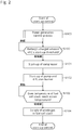
- Fig. 2 is a flow chart showing an example of the process procedure of the start-up control of the fuel cell system 10 in this embodiment.
- Step S900 the control unit 6 carries out the power generation control process wherein the switch-over timing of the working condition of the fuel cell stack 1 is determined.
- the switch-over timing of the fuel cell stack 1 includes the power generation timing to awake the fuel cell stack 1 from the state of being stopped so as to start up the power generation, the power increase timing to increase the power generation by the fuel cell stack 1, the stop timing to stop the power generation by the fuel cell stack 1, and the like.
- control unit 6 sets the FC's start-up threshold which determines the start-up timing of the fuel cell stack 1 as well as the FC's stop threshold which determines the stop timing to stop the power generation of the fuel cell stack 1. Meanwhile, with regard to the power generation control process in Step 900 will be explained later with referring to Fig. 3 .
- Step S100 the control unit 6 judges whether or not the charged amount of the battery 9 becomes equal to or less than the FC's start-up threshold. Then, if the charged amount of the battery 9 is more than the FC's start-up threshold, the control unit 6 waits start-up of the fuel cell stack 1 until the charged amount of the battery 9 reaches the FC's start-up threshold. On the other hand, when the charged amount of the battery 9 is decreased to the FC's start-up threshold, the process proceeds to Step S101.
- Step S101 when the charged amount of the battery 9 is decreased to the FC's start-up threshold, the control unit 6 starts up the compressor 32, and opens the cathode flow rate control valve 34, the control valve 341, and a control valve 342 with respective certain opening degrees. With this, the air (gas for burning) is supplied to the diffusion burner 352 and to the catalytic combustion burner 353.
- Step S102 the control unit 6 starts up the pump 21 and the diffusion burner 352 (ignition device), and also opens the control valves 231 to 233. With this, the fuel for heating-up is supplied to the diffusion burner 352, the catalytic combustion burner 353, and the discharged gas burner 40, respectively. Then, in the diffusion burner 352 the pre-heat burner is formed, and by using this pre-heat burner the combustion gas is formed in the catalytic combustion burner 353; and this combustion gas passes through the fuel cell stack 1 so that the fuel cell stack 1 is heated up.
- the combustion gas having passed through the fuel cell stack 1 reaches the discharged gas burner 40, whereby the discharged gas burner 40 is heated up by the catalytic combustion with the fuel for heating-up, and the heat exchanger 25 is heated up as well.
- the evaporator 24 and the heat exchanger 351 are heated up by the exhaust gas discharged from the discharge gas burner 40.
- Step S103 the control unit 6 judges whether or not the temperature of the fuel cell stack 1 reached the action temperature necessary for power generation of the fuel cell stack 1. Meanwhile, with regard to the judgement method of the temperature of the fuel cell stack 1, for example, if the temperature of the combustion gas detected by the temperature sensor goes beyond a certain value, then, with this, it may be judged that the fuel cell stack 1 reached the action temperature.
- Step S104 if the judgement is made that the temperature of the fuel cell stack 1 reached the action temperature thereof, the control unit 6 causes to stop the diffusion burner 352 and shuts off all the control valves 231, 232, 233, and 341, and opens the fuel supply valve 23.
- the fuel to be reformed that is stored in the fuel tank 20 becomes the anode gas while passing through the evaporator 24, the heat exchanger 25, and the reformer 26, thereby this anode gas is supplied to the anode electrode of the fuel cell stack 1.
- the air is continuously supplied from the cathode flow rate control valve 34, which is heated up in the heat exchanger 351, and then, supplied to the fuel cell stack 1 as the cathode gas.
- an electrochemical reaction between the anode gas and the cathode gas starts thereby starting the power generation as well; and with this, a series of the process procedure with regard to the stat-up control of this embodiment is over.
- Step S900 and Step S100 are carried out before execution of the start-up control by Steps S101 to S103; however, the processes of Step S900 and Step S100 may be carried out after execution of the start-up control by Steps S101 to S103, or these processes may be carried out in parallel.
- the fuel to be reformed that is supplied from the tank 20 is gasified by the evaporator 24; and then, the gasified fuel to be reformed is heated up by the heat exchanger 25. Then, the heated fuel to be reformed is reformed to the anode gas in the reformer 26; and then, this anode gas is supplied to the anode electrode of the fuel cell stack 1.
- the temperature of the air as the cathode gas is raised by the heat exchanger 351; and then, it is supplied to the cathode electrode of the fuel cell stack 1 after passing through the diffusion burner 352 and the catalytic combustion burner 353.
- the power is generated by the electrochemical reaction, and thereby this power is supplied to the DC-DC converter 51.
- the anode off-gas and the cathode off-gas after having been used in the electrochemical reaction are introduced into the discharged gas burner 40.
- these gases are burnt in the discharged gas burner 40 thereby becoming an exhaust gas, which thereafter heats up the evaporator 24 and the heat exchanger 351.
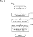
- Fig. 3 is a flow chart showing one example of the power generation control process that is carried out in Step S900 of this embodiment.
- Step S901 the control unit 6 acquires the charged amount of the battery 9.
- the control unit 6 in this embodiment acquires the battery SOC from the charged amount sensor 61. Meanwhile, it may also be allowed that a voltage sensor is arranged in the battery 9 to detect its own voltage, and on the basis of the detected value of the voltage sensor, the control unit 6 calculates the battery SOC or the charged amount according to a prescribed map, calculation formula, or the like.
- Step S902 the control unit 6 acquires the remaining amount of the fuel which can be supplied to the fuel cell stack 1.
- the control unit 6 in this embodiment acquires the remaining amount of the fuel to be reformed from the fuel amount sensor 62 as the remaining amount of the fuel of the fuel cell stack 1.
- the control unit 6 may calculate the remaining amount of the fuel by carrying out the time integration of the power amount generated by the fuel cell stack 1, or of the injection amount of the fuel by the fuel supply valve 23, or the like.
- Step S903 when the remaining amount of the fuel becomes small, the control unit 6 sets the FC's start-up threshold with regard to the battery SOC to a smaller value as compared with when the remaining amount of the fuel is large. For example, when the request power requested by the driving motor 81 is increased rapidly, the FC's start-up threshold is set such that, taking the start-up time, etc. of the fuel cell system 10 into consideration, the charged amount of the battery 9 may not be deficient owing to the insufficient power generation due to delay in the response of the fuel cell stack 1.
- Step S903 the control unit 6 may change the FC's start-up threshold so as to be lower as the remaining amount of the fuel decreases.
- the FC's start-up threshold becomes higher as the remaining amount of the fuel increases; and thus, the situation can be avoided that the charged amount of the battery 9 becomes deficient under the state that the much fuel is remained thereby resulting in the situation that the request power of the driving motor 81 cannot be obtained.
- the FC's start-up threshold becomes lower as the remaining amount of the fuel decreases, consumption of the fuel not contributing to power generation of the fuel cell stack 1 can be suppressed.
- the FC's start-up threshold may be set, for example, to zero so as to prohibit the fuel cell stack 1 from starting up. With this, useless start-up of the fuel cell stack 1 not contributing to charging of the battery 9 can be suppressed.
- the control unit 6 sets the target generated power, which is the target value of the generated power of the fuel cell stack 1, to a prescribed power value.
- This prescribed power value may be previously obtained by an experiment or the like, or may be changed to a larger value in response to rapid increase in the request power of the driving motor 81.
- Step S903 When the process of Step S903 is over, the process returns to the process procedure shown in Fig. 2 , thereby proceeding to the process of Step S100; and when the battery SOC becomes equal to or less than the FC's start-up threshold, the start-up control of the fuel cell system 10 is carried out.
- the method for controlling the fuel cell system 10 includes the charged amount acquiring Step S901 in which the charged amount of the battery 9 is acquired, and the power generation control Steps S100 to S103 in which when the charged amount of the battery 9 becomes equal to or less than the FC's start-up threshold (prescribed value), the fuel cell stack 1 is caused to be started up from the state of being stopped.
- the fuel cell system 10 like this supplies the fuel-containing anode gas and the oxidant-containing cathode gas to the fuel cell stack 1 so as to cause the fuel cell stack 1 to generate the power, and outputs this generated power to the battery 9.
- this control method includes: the fuel amount acquiring Step S902 in which the remaining amount of the fuel that can be supplied to the fuel cell stack 1 is acquired; and the setting Step S903 in which when the remaining amount of the fuel becomes small, the FC's start-up threshold is set to a lower value as compared with when the remaining amount of the fuel is large.
- FC's start-up threshold higher when the remaining amount of the fuel is large, consumption of the fuel is facilitated in preference to consumption of the charged amount of the battery 9; and thus, the situation that the charged amount of the battery 9 becomes deficient under the state that a large quantity of the fuel is remained can be suppressed.
- FC's start-up threshold is made lower when the remaining amount of the fuel becomes less, number of the start-up of the fuel cell stack 1 due to repeat of the charge and discharge of the battery 9 can be reduced; and thus, consumption of the fuel for heating-up not contributing to power generation of the fuel cell stack 1 can be reduced.
- the fuel cell stack 1 is caused to be started up so as to charge the generated power of the fuel cell stack 1 to the battery 9; and thus, deficiency of the charged amount of the battery 9 can be suppressed.
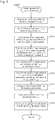
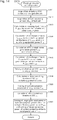
- Fig. 4 is a flow chart showing one example of the power generation control process in the second embodiment of the present invention. Because compositions of the fuel cell system of this embodiment are the same as those of Fig. 1 , hereunder, explanation will be made by giving the same symbol to the same component.
- Step S911 the control unit 6 acquires the battery SOC from the charged amount sensor 61.
- Step S912 the control unit 6 acquires the remaining amount of the fuel from the fuel amount sensor 62; and on the basis of the remaining amount of the fuel thus acquired, the remaining hydrogen amount H rest is estimated in accordance with a prescribed calculation formula. Namely, the control unit 6 acquires the remaining hydrogen amount H rest as the remaining amount of the fuel that can be supplied to the fuel cell stack 1.
- Step S913 the control unit 6 acquires a vehicle's power consumption, which shows the consumed power value of the load equipment 8.
- the control unit 6 records the acquired vehicle's power consumption values in the history information, which chronically shows the vehicle's power consumption values obtained in the past, and calculates the running load history P _vehicle by using this history information. Because the vehicle's power consumption includes the request power (or actual consumed power) of the driving motor 81, the vehicle's power consumption increases as the press amount of the accelerator pedal becomes larger.
- the control unit 6 of this embodiment calculates as the running load history P _vehicle the moving average value of plural vehicle's power consumptions obtained during a prescribed period.
- the running load history P _vehicle is not limited to the moving average value, but it may be a representative value relating to plural vehicle's power consumptions obtained during a prescribed period, such as a central value, a most frequent value, or a maximum value; or it may be a representative value corrected in accordance with the degree of dispersion.
- Step S914 the control unit 6 calculates the battery's discharge amount Startup during the FC's start-up period, wherein this discharge amount shows the power amount discharged from the battery 9 during the start-up period T_ startup of the fuel cell stack 1.
- the battery's discharge amount S _startup during the FC's start-up period used herein shows the ratio of the discharged power amount during the FC's start-up period to the rated capacity of the battery 9, and it is expressed by percentage.
- the battery's discharge amount Startup during the FC's start-up period can be calculated as follows. Namely, first, the discharged power of the battery 9 is obtained by adding the consumed power of the FC's auxiliary equipment, which is the auxiliary equipment of the fuel cell stack 1, to the vehicle's power consumption, and then, this discharged power is multiplied with the FC's start-up period T_ startup .
- the control unit 6 calculates the battery's discharge amount S_ startup during the FC's start-up period on the basis of the running load history P_ vehicle and the FC's auxiliary equipment power P_ fm , as shown in the following formula (1).
- the FC's auxiliary equipment power P_ fm is the power consumed by the auxiliary equipment of the fuel cell stack 1, wherein the FC's auxiliary equipment includes the pump 21, the compressor 32, the control valves 231 to 233, 341, and 342, etc.
- the power amount W [kWh] discharged from the battery 9 during the FC's start-up period T_ startup can be expressed by multiplying the rated capacity X_ batt of the battery 9 with the battery's discharge amount S _startup during the FC's start-up period.
- the power amount W [kWh] discharged from the battery 9 during the FC's start-up period T_ startup can be obtained by taking into consideration the charge and discharge efficiency E_ batt of the battery 9 in the consumed power amount obtained by multiplying the total consumed power (P_ vehicle +P_ fm ) of the loads connected to the battery 9 with the FC's start-up period T_ startup .
- the rated capacity X_ batt of the battery 9 is an upper limit value of the power amount chargeable to the battery 9.
- the total consumed power (P _vehicle +P _fm ) of the loads connected to the battery 9 is the sum of the running load history P _vehicle and the FC's auxiliary equipment power P _fm .
- the charge and discharge efficiency E_ batt of the battery 9 is expressed by percentage, wherein the power loss due to an internal resistance of the battery 9 is taken into consideration. Value of the FC's start-up period T_ startup can be obtained by an experiment or the like, wherein the unit thereof is second.
- FC's start-up threshold SOC_ rate Upon calculating the FC's start-up threshold SOC_ rate , by taking into consideration the battery's discharge amount S_ startup during the FC's start-up period as mentioned above, the situation that the charged amount of the battery 9 is deficient during start-up of the fuel cell stack 1 can be suppressed from happening.
- Step S915 the control unit 6 calculates the FC's rated power generation period T_ rate , which is the power generation period by the rated power generation of the fuel cell stack 1, on the basis of the fuel's remaining amount H rest of the fuel cell stack 1, as shown in the following formula (2).
- the power amount W [kWh] which can be generated by the fuel cell stack 1 with the rated power P_ rate during FC's rated power generation period T_ rate can be obtained by taking into consideration the power generation efficiency E_ rate of the fuel cell stack 1 in the power generation amount which is obtained by multiplying the fuel's remaining amount after start-up (H rest -H startup ) with the amount of heat generation of the fuel (120000).
- the fuel's remaining amount after start-up (H rest -H startup ) can be obtained by subtracting the consumption H startup of the fuel for heating-up that is necessary to start up the fuel cell stack 1 from the fuel's remaining amount H rest .
- the consumption H startup of the fuel for heating-up is the value which can be obtained by an experiment or the like.
- the power generation efficiency E_ rate of the fuel cell stack 1 is the power generation efficiency when the fuel cell stack 1 generates the power with the rated power P_ rate .
- the unit of the FC's rated power generation period T_ rate is second.
- T_ rate 3600 H rest ⁇ H startup ⁇ 120000 P _ rate ⁇ E _ rate 100
- the FC's rated power generation period T_ rate Upon calculating the FC's rated power generation period T_ rate , by taking into consideration the consumption H startup of the fuel for heating-up that is necessary to start up the fuel cell stack 1, start-up of the fuel cell stack 1 not contributing to charging of the battery 9 can be suppressed; and in addition, the situation that the charged amount of the battery 9 is deficient under the state that fuel of the fuel cell stack 1 remains can be suppressed from happening. Meanwhile, in view of the relationship in the formula (2), the FC's rated power generation period T_ rate becomes shorter as the fuel's remaining amount H rest becomes less.
- Step S916 the control unit 6 calculates the battery's discharge amount S_ assist during the FC's rated power generation period T_ rate on the basis of the vehicle's running load history P_ Vehicle , as shown by the following formula (3).
- the power amount W [kWh] that is discharged from the battery 9 during the FC's rated power generation period T_ rate can be obtained by multiplying the discharged power (P_ vehicle -P_ rate ) of the battery 9 with the FC's rated power generation period T_ rate .
- the discharged power (P_ vehicle -P_ rate ) of the battery 9 in the FC's rated power generation period T_ rate can be obtained by subtracting the rated power P_ rate of the fuel cell stack 1 which assists the battery 9 from the running load history P_ vehicle .
- the FC's rated power generation period T_ rate becomes shorter as the fuel's remaining amount H rest decreases, so that the battery's discharge amount S_ assist during the FC's rated power generation period decreases as the fuel's remaining amount H rest decreases.
- Step S917 in order to suppress the deficiency of the charged amount of the battery 9 under the state that the fuel of the fuel cell stack 1 remains, the control unit 6 sets the offset value SOC_ offset .
- the offset value SOC_ offset shows the battery SOC value with which the output of the battery 9 must be ensured when all the remaining amount of the fuel is consumed. Meanwhile, with regard to how to set the offset value SOC_ offset will be explained later with referring to Fig. 9 and Fig. 10 .
- Step S918 the control unit 6 calculates the FC's start-up threshold that determines the start-up timing of the fuel cell stack 1. This FC threshold is set such that the charged amount of the battery 9 may not be deficient before all the fuel in the tank 20 is consumed.
- the control unit 6 of this embodiment calculates the FC's start-up threshold SOC_ rate by using the offset value SOC_ offset , the battery's discharge amount S_ assist during the FC's rated power generation period, and the battery's discharge amount S_ startup during the FC's start-up period, as shown in the next formula (4).
- SO C _ rate min SO C _ reg , SO C _ offset + S _ assist + S _ startup
- FC's start-up threshold SOC_ rate Upon calculating the FC's start-up threshold SOC_ rate , by taking into consideration the battery's discharge amount Startup during the FC's start-up period, the FC's start-up threshold SOC_ rate is significantly corrected, so that the situation that the charged amount of the battery 9 is deficient during start-up of the fuel cell stack 1 can be avoided from happening.
- the FC's start-up threshold SOC_ rate in the formula (4) becomes lower as the fuel's remaining amount H rest decreases. Namely, as the fuel's remaining amount H rest decreases, start-up of the fuel cell stack 1 is suppressed more; and as the fuel's remaining amount H rest increases, start-up timing of the fuel cell stack 1 becomes quicker.
- the FC's stop threshold SOC_ reg in the formula (4) is the battery SOC to determine the stop timing of the fuel cell stack 1.
- the FC's stop threshold SOC_ reg is the value which can be obtained by an experiment or the like, wherein this is set so as to be larger than the FC's start-up threshold SOC_ rate .
- the FC's stop threshold SOC_ reg and the FC's start-up threshold SOC_ rate are provided with hysteresis, so that actions of start-up and stop of the fuel cell stack 1 can be stabilized.
- Step S919 if judgement is made that the battery SOC reached the FC's start-up threshold SOC_ rate , the control unit 6 sets the target power generation of the fuel cell stack 1 to the rated power P_ rate , and with this, a series of the process procedure with regard to the power generation control process of this embodiment is over. After this, in order to carry out the start-up control of the fuel cell system 10, the control unit 6 returns to the process procedure shown in Fig. 2 , and the process proceeds to Step S100.
- control unit 6 causes to start the diffusion burner 352, the catalytic combustion burner 353, etc., so as to raise the temperature of the fuel cell stack 1 to the action temperature necessary for the rated power generation; and then, it causes to supply the anode gas and the cathode gas to the fuel cell stack 1 with respective flow rates necessary for the rated power generation.
- the FC's start-up threshold SOC_ rate is set so as to be at least more than the offset value SOC_ offset , and also so to be higher as the fuel's remaining amount H rest increases.
- FC's start-up threshold SOC_ rate is set so as to be lower as the fuel's remaining amount H rest decreases, provided that the battery SOC at the time when all the fuel's remaining amount H rest is consumed is not less than the offset value SOC_ offset . With this, number of the start-up of the fuel cell stack 1 can be reduced with ensuring the charged amount of the battery 9.
- FC's start-up threshold SOC_ rate is set so as to be higher as the vehicle's running load history P_ vehicle increases.
- Fig. 5 is a figure showing the setting method to set the generated power of the fuel cell stack 1 in this embodiment.
- the horizontal axis indicates the battery SOC
- the vertical axis indicates the target output power of the fuel cell system 10.
- the target output power of the fuel cell system 10 is the target value of the generated power of the fuel cell stack 1 that must be outputted to at least any one of the driving motor 81 and the battery 9 from the fuel cell system 10.
- the control unit 6 sets the offset value SOC_ offset , and calculates the battery's discharge amount S _assist during the FC's rated power generation period and the battery's discharge amount S_ startup during the FC's start-up period on the basis of the vehicle's running load history P_ vehicle .
- a sum of SOC_ offset , S_ assist , and S_ startup is less than the FC's stop threshold SOC_ reg , so that the control unit 6 sets this sum as the FC's start-up threshold SOC_ rate .
- the control unit 6 causes the fuel cell stack 1 to start up, so that it can generate the power.
- the fuel cell stack 1 is kept under the state of being stopped.
- the power is outputted from the battery 9 to the driving motor 81 thereby causing the decrease in the battery SOC, whereby when the battery SOC is decreased to the FC's start-up threshold SOC_ rate , the start-up control of the fuel cell system 10 is carried out.
- FC's start-up section only the FC's auxiliary equipment such as the pump 21 and the compressor 32 is started up, with the power generation of the fuel cell stack 1 being zero. Therefore, the total power consumption of the vehicle's power consumption added with the power consumption of the FC auxiliary equipment is covered only by the battery 9.
- the target output power of the fuel cell system 10 is set to the rated power P_ rate of the fuel cell stack 1.
- the control unit 6 causes to start up the diffusion burner 352, the catalytic combustion burner 353, the discharged gas burner 40, etc., so as to raise the respective temperatures to the respective temperature ranges in which the fuel cell stack 1 can carry out the rated power generation.
- the control unit 6 causes to drive the fuel supply valve 23, the compressor 32, etc., so as to supply the anode gas and the cathode gas to the fuel cell stack 1 with the respective flow rates necessary to carry out the rated power generation.
- the target output power of the fuel cell system 10 is set to the rated power P_ rate of the fuel cell stack 1.
- the control unit 6 controls the temperature of the fuel cell stack 1, the supply amount of the anode gas, and the supply amount of the cathode gas, such that the fuel cell stack 1 can generate the power with the rated power P_ rate .
- the battery SOC with the amount of the offset value SOC_ offset can be ensured.
- the battery SOC becomes larger than the offset value SOC_ offset .
- the running load history P_ vehicle becomes zero, all the generated power of the fuel cell stack 1 is charged in the battery 9, so that the battery SOC increases.
- the control unit 6 stops power generation of the fuel cell stack 1. With this, useless power generation of the fuel cell stack 1 can be suppressed.
- the offset value SOC_ offset is previously determined such that even in the case that the running load history P_ vehicle increases, the battery 9 may not undergo the over-discharge when the fuel's remaining amount H rest runs out.
- FC's start-up threshold SOC_ rate which determines the start-up timing of the fuel cell stack 1 is set in accordance with the fuel's remaining amount H rest that can be supplied to the fuel cell stack 1, the charged amount necessary to protect the battery 9 can be ensured even when all of the fuel is consumed. Further, even in the case that the power consumption of the driving motor 81 rapidly increases at the time when the fuel's remaining amount H rest is small, by making the fuel cell stack 1 generate the power with the rated power P_ rate , over-discharge of the battery 9 due to the response delay of the fuel cell stack 1 can be suppressed with ensuring the request output of the driving motor 81.
- Fig. 6 shows one example of the relationship between the running load history P_ vehicle and the FC's start-up threshold SOC_ rate
- the discharge power of the battery 9 increases as the running load history P_ vehicle increases relative to the rated power P_ rate of the fuel cell stack 1, so that probability that the battery 9 undergoes over-discharge becomes high. Because of this, as the running load history P vehicle increases relative to the rated power P_ rate of the fuel cell stack 1, the control unit 6 raises the FC's start-up threshold SOC_ rate in order to quicken the assisting timing of the power supply from the battery 9 to the driving motor 81.
- Fig. 7 is a time chart illustrating the change in the output of the fuel cell system 10 with the change of the battery SOC in this embodiment.
- Fig. 7 the change of the battery SOC is shown by the solid line, and the change of the output power of the fuel cell system 10 is shown by the dotted line.
- the power is supplied to the load equipment such as the driving motor 81 only from the battery 9. Therefore, the battery SOC gradually decreases.
- the battery SOC reaches the FC's start-up threshold SOC_ rate , so that the start-up control of the fuel cell stack 1 starts.
- the FC's auxiliary equipment power P_ fm is necessary.
- the lowering rate of the battery SOC is large in the FC's start-up period T_ startup , wherein the battery SOC decreases lowered by the battery's discharge amount S_ startup in the FC's start-up period.
- the charged amount of the battery 9 with the amount of the offset value SOC_ offset can be properly ensured.
- the fuel cell stack 1 carries out the power generation with the rated power P_ rate , with facilitating the fuel consumption of the fuel cell stack 1 the decrease in the charged amount of the battery 9 can be suppressed.
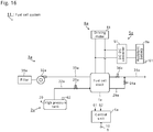
- Fig. 8 is a time chart when the fuel cell stack 1 carries out the power generation operation in accordance with the battery SOC after completion of start-up of the fuel cell system 10.
- the embodiment is presumed that after completion of start-up of the fuel cell stack 1, namely after the temperature of the fuel cell stack 1 reaches the action temperature capable of performing the rated power generation, judgement is made whether or not the acquired battery SOC is equal to or less than the FC's start-up threshold SOC_ rate .
- the battery's discharge amount S_ startup during the FC's start-up period is set to zero.
- Fig. 8 the change in the battery SOC is shown by the solid line, and the change in the fuel's remaining amount H rest is shown by the dotted line.
- the power is supplied to the load equipment 8 such as the driving motor 81 only from the battery 9. Therefore, the battery SOC decreases gradually.
- the battery SOC reaches the FC's start-up threshold SOC_ rate , so that the power generation by the fuel cell stack 1 with the rated power P_ rate starts. With this, the fuel's remaining amount H rest decreases gradually with passage of time. Meanwhile, as mentioned above, because the temperature of the fuel cell stack 1 is raised to the action temperature capable of performing the rated power generation, execution of the start-up control of the fuel cell stack 1 is omitted.
- the fuel cell stack 1 starts the power generation, the power is supplied not only from the battery 9 but also from the fuel cell stack 1; and thus, the discharge power of the battery 9 decreases. Because of this, the lowering rate of the battery SOC becomes slower.
- the fuel's remaining amount H rest becomes zero, so that the fuel cell stack 1 stops the power generation.
- the battery SOC with the amount of the offset value SOC_ offset is ensured. Because of this, during the fuel cell stack 1 is generating the power, the situation that the power supplied to the driving motor 81 decreases rapidly due to shortage of the battery SOC can be avoided.
- the situation that the charged amount of the battery 9 is deficient under the state that the fuel of the fuel cell stack 1 is remaining can be avoided. Accordingly, by efficiently utilizing the generated power of the fuel cell stack 1 with avoiding rapid decrease in the output of the driving motor 81, the charged amount of the battery 9 can be ensured.
- Fig. 9 is an explanatory figure showing one example of the setting method with which the offset value SOC_ offset to ensure the output of the battery 9 is set.
- the horizontal axis shows the battery margin, which shows the difference between the running load history P_ vehicle and the upper limit output which is the upper limit value of the output power of the battery 9, and the vertical axis shows the offset value SOC_ offset .
- the control unit 6 in this embodiment changes the offset value SOC_ offset in the range from the lower limit value SOC_ offset _ D to the upper limit value SOC_ offset _ H in accordance with the battery margin in the section from the first margin m1 to the second margin m2.
- the first margin m1 is the battery margin when the running load history P_ vehicle is increased to the vehicle's rated power P_ vehicle _ rate .
- the vehicle's rated power P_ vehicle_rate is the vehicle's power consumption when power consumption of the load equipment 8 becomes maximum. Meanwhile, the calculation method of the first margin m1 will be described with referring to the next figure.
- the second margin m2 is the value which can be obtained by an experiment or the like. For example, this is set to the battery margin when the running load history P_ vehicle becomes the value obtained by multiplying the vehicle's rated power with the coefficient "0.7".
- the control unit 6 lowers the FC's start-up threshold SOC_ rate as compared with the time when the battery margin is low.
- Fig. 10 is an explanatory figure showing one example of the calculation method to calculate the battery margin shown in Fig. 9 .
- Fig. 10(a) is an output characteristic figure showing the relationship between the battery's upper limit output and the battery SOC.
- Fig. 10(b) is an explanatory figure showing the calculation method of the first margin m1.
- the first margin m1 is set to the value which is obtained by subtracting the vehicle' rated power from the battery's upper limit output at the time when the battery SOC becomes the offset value SOC_ offset .
- the battery margin shown in Fig. 9 is calculated by subtracting the running load history P_ vehicle from the battery's upper limit output at the time when the battery SOC becomes the offset value SOC_ offset .
- the lower limit value SOC_ offset _ L of the offset value shown in Fig. 9 is determined by taking the output characteristics, etc. of the battery 9 into consideration.
- the battery margin is calculated by subtracting the running load history P_ vehicle from the battery's upper limit output at the time when the battery SOC becomes the offset value SOC_ offset .
- the difference between the battery's upper limit output of the battery SOC and the vehicle's power consumption at the moment may also be used as the battery margin.
- control unit 6 calculates the battery margin by taking the output characteristics of the battery 9 into consideration, wherein the offset value SOC_ offset is made lower as the battery margin becomes higher. With this, useless consumption of the fuel's remaining amount H rest by carrying out the power generation of the fuel cell stack 1 in spite that the battery SOC is sufficiently high can be suppressed. Therefore, the fuel consumption of the fuel cell stack 1 can be improved.
- the target generated power of the fuel cell stack 1 is set to the rated power P_ rate ; however, this may be set to a prescribed power which is lower than the rated power P_ rate . Even in the case like this, too, the charged amount of the battery 9 can be satisfactorily ensured after the remaining amount of the fuel is consumed.
- the control unit 6 changes the FC's start-up threshold SOC_ rate to a smaller value as the fuel's remaining amount H rest decreases.
- Step S900 in the power generation control process of Step S900, as shown in Fig. 8 , when the battery SOC decreases, the control unit 6 sets the target generated power of the fuel cell stack 1 to from zero to a higher prescribed power value as compared with when the battery SOC is high. With this, the situation that the charged amount of the battery 9 is deficient under the state that the fuel of the fuel cell stack 1 remains can be suppressed.
- the prescribed power value which is set to the target generated power is preferably set to the rated power value P_ rate of the fuel cell stack 1.
- the control unit 6 when the battery SOC becomes equal to or less than the FC's start-up threshold SOC_ rate , the control unit 6 causes to increase in stages the target generated power of the fuel cell stack 1 so as to lower the ratio of the fuel's remaining amount H rest to the battery SOC.
- the fuel's remaining amount H rest of the fuel cell stack 1 decreases in preference to the charged amount of the battery 9; and thus, the situation that the charged amount of the battery 9 becomes deficient under the state that the fuel is remaining can be suppressed.
- the control unit 6 when the battery SOC becomes larger than a specific FC's stop threshold SOC_ reg , the control unit 6 causes the fuel cell stack 1 to stop the power generation thereof. And, the control unit 6 sets the FC's stop threshold SOC_ reg to the value greater than the FC's start-up threshold SOC_ rate .
- Step S913 the control unit 6 calculates the running load history P_ vehicle , which shows the change history of the power that is consumed in the load equipment 8. And, by using this running load history P_ vehicle the control unit 6 calculates in Step S914 the battery's discharge amount Startup in the FC's start-up period, and also in Step S916 it calculates the battery's discharge amount S_ assist in the FC's rated power generation period. By using these calculation results, the control unit 6 calculates in Step S918 the FC's start-up threshold SOC_ rate .
- control unit 6 corrects the FC's start-up threshold SOC_ rate in accordance with the change history of the load equipment 8 that is connected to the battery 9. With this, the start-up timing of the fuel cell stack 1 is quickened in accordance with an increase in the amount of the discharged power from the battery 9 to the load equipment 8; and thus, with facilitating the fuel consumption of the fuel cell stack 1, the situation that the charged amount of the battery 9 is deficient can be avoided more surely.
- control unit 6 raises the FC's start-up threshold SOC _rate as the running load history P _vehicle -this shows the moving average value of the power consumption of the load equipment 8-increases.
- the start-up timing of the fuel cell stack 1 is quickened as the running load history P_ vehicle increases; and thus, the decrease in the charged amount of the battery 9 can be suppressed by reducing the remaining amount of the fuel.
- the moving average value of the power consumption of the load equipment 8 frequent change of the FC's start-up threshold SOC_ rate caused by change of the power consumption of the load equipment in short period of time can be avoided. Accordingly, the situation that start-up and stop of the fuel cell stack 1 are repeated can be suppressed.
- Step S915 the control unit 6 calculates the FC's rated power generation period T_ rate by using the consumption H startup of the fuel for heating-up that is supplied to the diffusion burner 352, the catalytic combustion burner 353, and the discharged gas burner 40 during the start-up period of the fuel cell stack 1. And, in Step S916 the control unit 6 calculates the battery's discharge amount S _assist in the FC's rated power generation period T_ rate , and by using this calculation result, calculates in Step S918 the FC's start-up threshold SOC_ rate .
- control unit 6 corrects the FC's start-up threshold SOC_ rate to a lower value by using the consumption H statup of the fuel for heating-up that is necessary to start up the fuel cell stack 1. With this, the start-up timing of the fuel cell stack 1 is delayed, or even the start-up itself is suppressed; and thus, the start-up of the fuel cell stack 1 not contributing to charging of the battery 9 can be suppressed.
- control unit 6 obtains in Step S915 the FC's rated power generation period T_ rate during which the fuel cell stack 1 generates the power with the rated power P_ rate on the basis of the fuel's remaining amount H rest ; and in Step S916 it calculates in accordance with the power consumption of the load equipment 8 the battery's discharge amount S_ assist in the FC's rated power generation period T_ rate . And further, control unit 6 calculates in Step S918 the FC's start-up threshold SOC_ rate by adding the battery's discharge amount S_ assist during the FC's rated power generation period to the offset value SOC_ offset .
- the control unit 6 sets the offset value SOC_ offset to a lower value as the battery margin increases larger, wherein this margin shows the difference between the battery's upper limit power and the vehicle's power consumption.
- the offset value SOC_ offset is made lower so that quickening of the start-up timing of the power generation of the fuel cell stack 1 more than necessary can be suppressed. With this, fuel consumption with poor efficiency in the fuel cell stack 1 can be suppressed, so that fuel consumption of the fuel cell system 10 can be improved.
- the next embodiment is provided with, in addition to the battery protective driving mode by the rated power generation of the fuel cell stack 1, the driving mode which prioritizes the fuel consumption wherein the fuel consumption of the fuel cell system 10 can be improved.
- Fig. 11 is the explanatory figure showing the relationship between the target output power of the fuel cell system 10 and the charged amount of the battery 9 in the third embodiment of the present invention.
- two driving sections the battery protective driving section and the fuel consumption prioritized driving section, are configured.
- the battery protective driving section is the same as the driving section of the fuel cell stack 1 from the lower limit value of the battery SOC to the threshold SOC_ rate , as shown in Fig. 5 .
- the control unit 6 prioritizes security of the charged amount of the battery 9 thereby setting the generated power of the fuel cell system 1 to the rated power P_ rate .
- the temperature of the fuel cell stack 1 needs to be kept in the upper limit side in the temperature range in which the power can be generated.
- the fuel consumption prioritized driving section S_ fit is configured in the battery SOC region which is higher than the drive switching threshold SOC_ rate which is a lower limit value of the battery protection driving section.
- the control unit 6 sets the target generated power of the fuel cell stack 1 to the high efficiency power value P_ eco which is lower than the rated power value P_ rate .
- the high efficiency power value P_ eco is set to the power value at which the energy efficiency of the fuel cell stack 1 is the highest under the condition that temperature of the fuel cell stack 1 is kept in the lower side in the temperature range in which the power can be generated.
- the battery protective driving section by setting the fuel consumption prioritized driving section S_ fit in the way as mentioned above, the number of start-up of the fuel cell stack 1 can be reduced, so that consumption of the fuel for heating-up used in the start-up control can be reduced.
- the energy efficiency of the entire system can be enhanced so that the fuel consumption can be improved.
- Fig. 12 is a conceptual figure with regard to the energy efficiency in the battery protective drive and the fuel consumption prioritized drive.
- the horizontal axis shows the generated power of the fuel cell stack 1
- the vertical axis shows the energy efficiency of the fuel cell stack 1.
- the control unit 6 keeps the temperature of the fuel cell stack 1 in the lower limit side of the power generation capable temperature range, for example at 650°C, and causes the fuel cell stack 1 to generate the power such that the energy efficiency of the fuel cell stack 1 may be the high efficiency power value P_ eco which is the highest in the energy efficiency. Namely, the control unit 6 causes to supply to the fuel cell stack 1 the anode gas and the cathode gas with the respective flow rates necessary to carry out the power generation with the high efficiency power value P_ eco . At the same time, the control unit 6 operates the DC-DC converter 51 so as to cause the fuel cell stack 1 to raise the voltage thereof until the power that is taken out from the fuel cell stack 1 to the battery 9 reaches the voltage value of the high efficiency power value P_ eco .
- the control unit 6 causes to keep the temperature of the fuel cell stack 1 in the upper limit side of the power generation capable temperature range, for example at 750°C, and causes the fuel cell stack 1 to generate the power such that the generated power may be the rated power value P_ r ⁇ te corresponding to the lower limit voltage of the fuel cell stack 1. Namely, the control unit 6 causes to supply to the fuel cell stack 1 the anode gas and the cathode gas with the respective flow rates necessary to generate the power with the rated power value P_ rate . At the same time, the control unit 6 operates the DC-DC converter 51 so as to cause the fuel cell stack 1 to drop the voltage thereof until the power that is taken out from the fuel cell stack 1 to the battery 9 reaches the voltage value of the rated power value P_ rate .
- the control unit 6 causes to lower the temperature of the fuel cell stack 1 within the temperature range that the fuel cell stack 1 can generate the power, and also sets the generated power of the fuel cell stack 1 to a lower value.
- the control unit 6 causes to raise the temperature of the fuel cell stack 1 within the temperature range that the fuel cell stack 1 can generate the power by using the fuel for heating-up, and also sets the generated power of the fuel cell stack 1 to a higher value.
- Fig. 13 is an explanatory figure showing one example of the setting method to set the fuel consumption prioritized driving section S_ fit .
- the horizontal axis shows the running load history P_ vehicle
- the vertical axis shows the fuel consumption prioritized driving section S_ fit .
- the control unit 6 changes the fuel consumption prioritized driving section S_ fit in the range from the lower limit value S_ fit _ L to the upper limit value S_fit_H in accordance with the value of the running load history P_ vehicle .
- the control unit 6 expands the fuel consumption prioritized driving section S_ fit as compared with when the vehicle's power consumption is small. With this, the efficiency of power generation of the fuel cell stack 1 improves, so that the charged amount to the battery 9 from the fuel cell stack 1 increases, thereby the fuel consumption of the fuel cell system 10 can be improved.
- Fig. 14 is a flow chart showing one example of the power generation control process carried out by Step S900 in this embodiment.
- the power generation control process of this embodiment comprises processes of Steps S934, S935, and Steps S937 to S942 in place of the processes of Steps S914, S915, and Steps S917 to S920 shown in Fig. 4 . Because the other processes are the same as the processes shown in Fig. 4 , the explanation with regard to them is omitted while tagging with the same respective symbols as before.
- Step S934 the control unit 6 calculates the battery's discharge amount S_ startup in the FC's start-up period in accordance with the formula (1), in the same manner as the process of Step S914.
- the FC's start-up period T_ startup of this embodiment is the value obtained by integrating the start-up period which is the time necessary to transfer from the stopping state of the fuel cell stack 1 to the fuel consumption prioritized drive and the warming-up period which is the time necessary to transfer from the fuel consumption prioritized drive to the battery protective drive.
- the start-up period is the time necessary to raise the temperature of the fuel cell stack 1 to the temperature necessary to carry out the fuel consumption prioritized drive
- the warming-up period is the time necessary to raise the temperature of the fuel cell stack 1 from the temperature state of the fuel consumption prioritized drive to the temperature necessary to carry out the battery protective drive.
- Step S935 the control unit 6 calculates the FC's rated power generation period T _rate in accordance with the formula (2), similarly to the process of Step S915.
- the consumption H startup of the fuel for heating-up in this embodiment is set to the value which is obtained by adding the consumption of the start-up fuel necessary to raise the temperature of the fuel cell stack 1 to the action temperature of the fuel consumption prioritized drive and the consumption of the warm-up fuel necessary to warm up the fuel cell stack 1 till the action temperature of the battery protective drive from the temperature state of the fuel consumption prioritized drive.
- Step S937 the control unit 6 sets the offset value SOC _offset in order to ensure the output of the battery 9 in accordance with the battery margin, as shown in Fig. 9 .
- the first margin m1 in this embodiment is obtained by adding the high efficiency power P _eco to the value obtained by subtracting the vehicle's rated power from the battery's upper limit output, as shown in Fig. 15 .
- the battery margin is obtained by adding the high efficiency power P _eco to the value obtained by subtracting the running load history P _vehicle from the battery's upper limit output when the battery SOC reaches the upper limit value SOC _offset_H of the offset value.
- Step P938 the control unit 6 sets the drive switching threshold SOC _rate which determines the switch-over timing from the fuel consumption prioritized drive to the battery protective drive in accordance with the formula (4), similarly to the process of Step S918.
- Step S939 the control unit 6 sets the fuel consumption prioritized driving section S _fit in accordance with the value of the running load history P _vehicle , as shown in Fig. 13 .
- Step S940 the control unit 6 calculates the FC's start-up threshold S _eco which determines the start-up timing of the fuel cell stack 1, as shown in the next formula (5).
- SO C _ eco min SO C _ reg , SO C _ rate + S _ fit
- Step S941 the control unit 6 sets the target generated power at the time when the battery SOC drops to the FC's start-up threshold SOC _eco to the high efficiency power value P _eco , and the target generated power at the time when the battery SOC drops to the drive switching threshold SOC _rate to the rated power value P _rate .
- the control unit 6 carries out the start-up control by Steps S100 to S104 shown in Fig. 2 .
- the control unit 6 causes to raise the temperature of the fuel cell stack 1 till the lower limit side in the range of the power generation capable temperature, and at the same time, causes to supply to the fuel cell stack 1 the cathode gas and the anode gas with the respective flow rates necessary to carry out the power generation with the high efficiency power P _eco .
- the control unit 6 causes to raise the temperature of the fuel cell stack 1 till the upper limit side in the range of the power generation capable temperature, and at the same time, causes to supply to the fuel cell stack 1 the cathode gas and the anode gas with the respective flow rates necessary to carry out the power generation with the rated power P _rate .
- the control unit 6 when the battery SOC (charged amount) becomes the FC's start-up threshold (first threshold) SOC _eco , the control unit 6 causes to carry out the fuel consumption prioritized drive. Namely, when the battery SOC decreases to the FC's start-up threshold SOC _eco , the control unit 6 causes the fuel cell stack 1 to start up so that the fuel cell stack 1 generates the power with the high efficiency power P _eco which is lower than the rated power P _rate . With this, the energy efficiency of the fuel cell stack 1 is improved, so that the fuel consumption of the fuel cell system 10 can be improved.
- the control unit 6 switches over the driving state of the fuel cell stack 1 from the fuel consumption prioritized drive to the battery protective drive. Namely, when the battery SOC is decreased to the drive switching threshold SOC _rate , the control unit 6 causes to raise the temperature of the fuel cell stack 1 so as to increase the power generation of the fuel cell stack 1, as shown in Fig. 12 . By so doing, with facilitating consumption of the remaining amount of the fuel, the charged amount of the battery 9 can be ensured.
- the battery protective driving section as shown in Fig. 11 , the charged amount of the battery 9 can be secured after the remaining amount of the fuel is consumed, so that with suppressing the performance deterioration of the battery 9, decrease in the drivability can be suppressed.
- Step S935 the control unit 6 calculates the FC's rated power generation period T _rate by using the consumption H startup of the fuel for heating-up which is necessary for starting-up and warming-up of the fuel cell stack 1.
- the drive switching threshold SOC _rate and the FC's start-up threshold SOC _eco are calculated.
- the fuel cell stack 1 can be accurately started up so as to switch over to the battery protective drive without causing deficiency of the charged amount in the battery 9.
- the fuel consumption prioritized driving section S _fit is expanded. Namely, as the power consumption of the load equipment 8 connected to the battery 9 increases, the section from the FC' start-up threshold SOC _eco to the drive switching threshold SOC _rate is expanded.
- the start-up timing of the fuel cell stack 1 is quickened thereby prolonging the period wherein the power generation is carried out under the state that the energy efficiency of the fuel cell stack 1 is high; and thus, amount of power supply from the fuel cell stack 1 to the battery 9 can be increased, and the fuel consumption of the fuel cell system 10 can be improved as well.
- the fuel cell stack 1 is caused to generate a power at two driving points in accordance with the value of the battery SOC; however, the way thereof is not limited to this.
- three or more driving points may be set in the fuel cell stack 1, wherein the control unit 6 controls such that the generated power of the fuel cell stack 1 is decreased in stages as the battery SOC decreases. Even in this way, the energy efficiency of the fuel cell stack 1 can be improved as compared with the second embodiment.
- Fig. 16 is a composition figure showing one composition example of a fuel cell system 11 provided with a polymer electrolyte fuel cell.
- the fuel cell system 11 supplies a power to the driving motor 81 arranged in load equipment 8a and to an assistant battery 9a which assists a power of the fuel cell stack 1.
- the fuel cell system 11 comprises a fuel cell stack 1a which is a laminate of plural polymer electrolyte fuel cells, a fuel supply equipment 2a, an oxidant supply equipment 3a, a power converter 5a, and a control unit 6a which controls supply flow rates of the anode gas and the cathode gas to the fuel cell stack 1a on the basis of a request power of the driving motor 81.
- the fuel supply equipment 2a comprises a high pressure tank 20a which stores the anode gas at a high pressure, an anode gas supply path 22a, an anode pressure control valve 23a to control an anode gas pressure, a purge valve 24a to discharge the anode off-gas, and an anode gas discharge path 29a.
- the oxidant supply equipment 3a comprises a filter 30a, a compressor 32a, a cathode gas supply path 33a, a cathode pressure control valve 34a to control a cathode gas pressure, and a cathode gas discharge path 39a.
- the power converter 5a comprises the DC-DC converter 51 to supply the generated power of the fuel cell system 11 to the load equipment 8a or to the assistant battery 9a.
- the control unit 6a acquires the battery SOC from the charged amount sensor 61; and as shown in Step S100 of Fig. 2 , when the battery SOC becomes equal to or less than the FC's start-up threshold, it causes the fuel cell stack 1a to start up. And, the control unit 6a acquires from the fuel amount sensor 62 the remaining amount of the fuel that can be supplied to the fuel cell stack 1a; and as shown in Step S903 of Fig. 3 , when the remaining amount of the fuel becomes small, it sets the FC's start-up threshold to a lower value as compared with when the remaining amount of the fuel is large.
- start-up of the fuel cell stack 1a can be suppressed, so that consumption of the fuel for heating-up not contributing to charging of the battery 9a can be suppressed. Accordingly, fuel consumption of the fuel cell system 11 can be improved with ensuring the output of the battery 9a.
- start-up of the fuel cell is suppressed when the remaining amount of the fuel is small relative to the charged amount of the secondary battery, so that useless consumption of the fuel can be suppressed.
- power generation of the fuel cell increases, so that the shortage in the charged amount of the secondary battery can be covered. Therefore, over-discharge of the battery does not readily take place, so that the situation that the battery performance is damaged can be suppressed.
- control unit 6 carries out the power generation control process of Step S900 shown in Fig. 2 during start-up control of the fuel cell stack 1; however, this process may be carried out during power generation operation or stop control of the fuel cell stack 1.
- control unit 6 may always renew the thresholds SOC _rate and SOC _eco during the period from start-up to stop of the fuel cell system 10.
Landscapes
- Engineering & Computer Science (AREA)
- Sustainable Development (AREA)
- Sustainable Energy (AREA)
- Life Sciences & Earth Sciences (AREA)
- Chemical & Material Sciences (AREA)
- Chemical Kinetics & Catalysis (AREA)
- Electrochemistry (AREA)
- General Chemical & Material Sciences (AREA)
- Manufacturing & Machinery (AREA)
- Power Engineering (AREA)
- Mechanical Engineering (AREA)
- Transportation (AREA)
- Artificial Intelligence (AREA)
- Evolutionary Computation (AREA)
- Fuzzy Systems (AREA)
- Medical Informatics (AREA)
- Software Systems (AREA)
- Theoretical Computer Science (AREA)
- Computing Systems (AREA)
- Automation & Control Theory (AREA)
- Health & Medical Sciences (AREA)
- Fuel Cell (AREA)
- Electric Propulsion And Braking For Vehicles (AREA)
Abstract
Description
- The present invention relates to a fuel cell system which outputs a generated power of a fuel cell to a secondary battery and a method for controlling a fuel cell system.
- The
U. S. Laid-Open Patent Publication No. 2014/0113162 discloses in its specification a fuel cell system provided with a solid oxide fuel cell which receives a fuel and generates a power in accordance with a load. - The fuel cell system as mentioned above can also be used as the system in which in order to ensure an output of a secondary battery the generated power of a fuel cell is charged to a secondary battery which supplies a power to a load such as, for example, a motor.
- In the system like this, when the fuel cell is started up from the stopped state thereof, or power generation of the fuel cell is increased, temperature of the fuel cell needs to be raised to the action temperature suitable for power generation; and thus, besides a fuel for power generation, a fuel for warming up the fuel cell is necessary.
- Therefore, during start-up of the fuel cell or when the power generation thereof is increased, consumption of the fuel not contributing to charging of the secondary battery increases; and thus, as the number of repeat in start-up of the fuel cell and increase of power generation is increased, with responding it, the fuel consumption of the fuel cell system deteriorates.
- The present invention was made in view of the problem mentioned above. Therefore, the present invention has an object to provide the fuel cell system with which deterioration in the fuel consumption is suppressed while ensuring the output of the secondary battery, and also to provide the method for controlling the fuel cell system.
- According to an aspect of this invention, there is provided a method for controlling a fuel cell system in which a fuel and an oxidant are supplied to a fuel cell and a generated power from the fuel cell is outputted to a secondary battery. The method includes a charged amount acquisition step in which a charged amount of the secondary battery is acquired, a power generation control step in which when the charged amount of the secondary battery becomes equal to or less than a prescribed value, the fuel cell is started up from a state that the fuel cell stops power generation, or the generated power of the fuel cell is increased, a fuel amount acquisition step in which a remaining amount of the fuel which can be supplied to the fuel cell is acquired, and a setting step in which when the remaining amount of the fuel becomes small, the prescribed value is set to a smaller value as compared with when the remaining amount of the fuel is large.
-
- [
Fig. 1 ]
Fig. 1 is a block diagram showing main components of the fuel cell system in the first embodiment of the present invention. - [
Fig. 2 ]
Fig. 2 is a flow chart showing one example of the start-up method of the fuel cell system in this embodiment. - [
Fig. 3 ]
Fig. 3 is a flow chart exemplifying content of the power generation control process of the fuel cell in this embodiment. - [
Fig. 4 ]
Fig. 4 is a flow chart exemplifying content of the power generation control process of the fuel cell in the second embodiment of the present invention. - [
Fig. 5 ]
Fig. 5 is an explanatory figure showing the relationship between the charged amount of the battery and the generated power of the fuel cell in this embodiment. - [
Fig. 6 ]
Fig. 6 is an explanatory figure showing one example of the setting method with which an FC's start-up threshold which determines the start-up timing of the fuel cell stack is set in accordance with the running load history. - [
Fig. 7 ]
Fig. 7 is a time chart showing the change of a generated power of the fuel cell in accordance with charged amount of the battery. - [
Fig. 8 ]
Fig. 8 is a time chart showing the change of remaining amount of the fuel in accordance with the charged amount of the battery. - [
Fig. 9 ]
Fig. 9 is an explanatory figure showing one example of the setting method with which the offset value that is determined for the battery protection is set in accordance with the battery margin. - [
Fig. 10 ]
Fig. 10 is an explanatory figure showing one example of the calculation method of the battery margin. - [
Fig. 11 ]
Fig. 11 is an explanatory figure exemplifying the relationship between the charged amount of the battery and the generated power of the fuel cell in the third embodiment of the present invention. - [
Fig. 12 ]
Fig. 12 is an explanatory figure showing the energy efficiency of the fuel cell in the fuel consumption prioritized drive and the battery protective drive. - [
Fig. 13 ]
Fig. 13 is a figure showing one example of the setting method with which a section of the fuel consumption prioritized drive is set in accordance with the running load history. - [
Fig. 14 ]
Fig. 14 is a flow chart exemplifying content of the power generation control process of the fuel cell in this embodiment. - [
Fig. 15 ]
Fig. 15 is an explanatory figure showing one example of the calculation method with which the battery margin to set the offset value is calculated. - [
Fig. 16 ]
Fig. 16 is a block diagram showing main components of the fuel cell system in the fourth embodiment of the present invention. - Hereunder, embodiments of the present invention will be explained with referring to the figures.
-
Fig. 1 is a block diagram showing main components of thefuel cell system 10 in the first embodiment of the present invention. - The
fuel cell system 10 is a battery auxiliary system to cause afuel cell stack 1 to generate a power in accordance with the charge condition of abattery 9. Thefuel cell system 10 of this embodiment is the fuel cell system with which the generated power is supplied to load equipment 8 or thebattery 9 mounted on a vehicle. - The load equipment 8 is an electric load connected to the
battery 9 and to thefuel cell system 10. The load equipment 8 includes adriving motor 81 whose electric load changes. The load equipment 8 of this embodiment includes, besides thedriving motor 81, a room air conditioner, vehicle auxiliary equipment, etc., which are not shown in the figure. - The driving
motor 81 is a power source to drive the vehicle. The drivingmotor 81 generates a regenerative power upon applying a break to the vehicle, wherein this regenerative power can be charged in thebattery 9. - The
battery 9 is a power supply source to thedriving motor 81, and this is realized, for example, by a lithium ion battery, a lead storage battery, or the like. Thebattery 9 charges the regenerative power of the drivingmotor 81 and the power outputted from thefuel cell system 10. In this embodiment, the rated output power of thebattery 9 is larger than the rated output power of thefuel cell stack 1. Namely, thebattery 9 is a main power supply source to the load equipment 8, and thefuel cell stack 1 is an auxiliary power supply source to the load equipment 8. - The
battery 9 is provided with acharged amount sensor 61 to detect the charged amount (remaining amount) showing the power stored in thebattery 9. Thecharged amount sensor 61 of this embodiment detects the state of charge (SOC) of thebattery 9 as the charged amount of thebattery 9, and outputs this detected value to a control unit 6. As the charged amount of thebattery 9 increases, the SOC of thebattery 9 increases. Hereinafter, the SOC of thebattery 9 is called as "battery SOC". - The
fuel cell system 10 comprises fuel supply equipment 2 which supplies an anode gas (fuel gas) to thefuel cell stack 1 andoxidant supply equipment 3 which supplies a cathode gas (oxidant gas) to thefuel cell stack 1. In addition, thefuel cell system 10 is provided withgas discharge equipment 4 which discharges an anode-off gas (fuel off-gas) and a cathode off-gas (oxidant off-gas), these gases being discharged from thefuel cell stack 1 to outside. Thegas discharge equipment 4 comprises an anodegas discharge path 29 and a cathodegas discharge path 39, as well as a dischargedgas burner 40 and an exhaustgas discharge path 41. Further, thefuel cell system 10 comprises: power converting equipment 5, which takes out the power from thefuel cell stack 1 and supplies it to at least any one of the load equipment 8 and thebattery 9; and the control unit 6 which controls the whole of the fuel cell system. - The
fuel cell stack 1 is a solid oxide fuel cell (SOFC). Thefuel cell stack 1 is a stack of a plurality of the cells, each of which has a composition that an electrolyte layer formed of a solid oxide such as a ceramic is sandwiched between an anode electrode (fuel electrode) and a cathode electrode (air electrode). - To the anode electrode of the
fuel cell stack 1 is supplied the anode gas that is reformed by the fuel supply equipment 2, and to the cathode electrode of thefuel cell stack 1 is supplied an air including oxygen, as the cathode gas, by theoxidant supply equipment 3. In thefuel cell stack 1, hydrogen included in the anode gas is caused to react with oxygen included in the cathode gas thereby generating a power, and at the same time, the anode off-gas and the cathode off-gas that are formed after the reaction are discharged to an outside air. - To a manifold formed in the anode side of the
fuel cell stack 1 are connected an anodegas supply path 22 and an anodegas discharge path 29 both of which constitute the path through which the anode gas flows; and to a manifold formed in the cathode side thereof are connected a cathodegas supply path 33 and a cathodegas discharge path 39 both of which constitute the path through which the cathode gas flows. - The anode
gas supply path 22 is a route along which the anode gas is supplied to thefuel cell stack 1, and the anodegas discharge path 29 is a route along which the anode off-gas from thefuel cell stack 1 is introduced into the dischargedgas burner 40. Also, the cathodegas supply path 33 is a route along which the cathode gas is supplied to thefuel cell stack 1, and the cathodegas discharge path 39 is a route along which the cathode off-gas from thefuel cell stack 1 is introduced into the dischargedgas burner 40. - The fuel supply equipment 2 comprises a
fuel tank 20, apump 21, the anodegas supply path 22, afuel supply valve 23, anevaporator 24, aheat exchanger 25, and areformer 26. - The
fuel tank 20 stores a liquid including a fuel. In thefuel tank 20, a fuel to be reformed, for example, a liquid formed of mixture of ethanol and water is stored. Thefuel tank 20 is provided with afuel amount sensor 62. Thefuel amount sensor 62 detects a remaining amount of the fuel to be reformed that is stored in thefuel tank 20. The detected value of thefuel amount sensor 62 is outputted to the control unit 6. - The
pump 21 sucks the fuel to be reformed so as to supply it to the fuel supply equipment 2 with a certain pressure. - The anode
gas supply path 22 is the path which connects between thepump 21 and thefuel cell stack 1. The anodegas supply path 22 comprises thefuel supply valve 23, theevaporator 24, theheat exchanger 25, and thereformer 26. - The
fuel supply valve 23 supplies to an injection nozzle the fuel to be reformed that is supplied from thepump 21 thereby injecting the fuel to be reformed into the evaporator 24 from the injection nozzle. - The
evaporator 24 gasifies the fuel to be reformed by utilizing a heat of the exhaust gas that is discharged from the dischargedgas burner 40. - In order to reform the fuel to be reformed in the
reformer 26, by the heat that is supplied from the dischargedgas burner 40, theheat exchanger 25 further heats up the fuel to be reformed that is gasified. - The
reformer 26 reforms the fuel to be reformed to the anode gas including hydrogen by a catalytic reaction thereby supplying the anode gas to the anode electrode of thefuel cell stack 1. In thereformer 26, a steam reformation, in which the fuel is reformed by using a steam, is carried out, wherein in the case that the steam necessary for the steam reformation is insufficient, partial oxidation reformation, in which reformation is done by burning the fuel with an air instead of a steam, is carried out. - The
oxidant supply equipment 3 comprises afilter 30, anair aspiration path 31, acompressor 32, the cathodegas supply path 33, and a cathode gas flowrate control valve 34, as well as heating equipment comprising aheat exchanger 351, adiffusion burner 352, and acatalytic combustion burner 353. - The
filter 30 removes foreign matters included in the outside air so as to introduce this air to inside thefuel cell system 10. - The
air aspiration path 31 is the path through which the air having the foreign matters removed by thefilter 30 is supplied to thecompressor 32. On end of theair aspiration path 31 is connected to thefilter 30, and the other end is connected to a suction port of thecompressor 32. - The
compressor 32 is an actuator so as to supply the cathode gas to thefuel cell stack 1. Thecompressor 32 of this embodiment takes in the outside air through thefilter 30, and then supplies this air to thefuel cell stack 1, etc. - To the cathode
gas supply path 33 is attached arelief valve 36. When the pressure inside the cathodegas supply path 33 goes beyond a certain value, it opens the cathodegas supply path 33 so as not to apply a load more than a certain value to thecompressor 32. - The cathode flow
rate control valve 34 is a control valve to control a flow rate of the cathode gas that is supplied to thefuel cell stack 1. For example, the cathode flowrate control valve 34 is composed of an electromagnetic valve. The opening degree of the cathode flowrate control valve 34 can be changed in stages, and it is controlled by the control unit 6. - The
heat exchanger 351 heats up the air for the combustion gas or the air for the cathode gas by utilizing a heat of the exhaust gas discharged from the dischargedgas burner 40. - At the start-up of the
fuel cell system 10, the air heated by theheat exchanger 351 and the fuel for heating-up, which is supplied from abranch path 222 and is heated up by anelectric heater 242, are supplied into thediffusion burner 352 so as to be mixed. And, with an ignition device attached to thediffusion burner 352, the mixture of the air and the fuel for heating-up is burnt to constitute a pre-heat burner for thecatalytic combustion burner 353. After completion of the start-up, the air supplied from theheat exchanger 351 is supplied to thecatalytic combustion burner 353. - At the start-up of the
fuel cell system 10, thecatalytic combustion burner 353 generates a high temperature combustion gas by using a catalyst and a pre-heat burner. In thecatalytic combustion burner 353, the air for the combustion gas supplied via abranch path 331 and the fuel for heating-up supplied from abranch path 223 are mixed under the state that these gases are contacted with a combustion catalyst. And, by igniting the mixture of the air and the fuel for heating-up with the pre-heat burner, a large quantity of the combustion gas is generated. This combustion gas is mainly composed of an inert gas not including oxygen. The combustion gas is supplied to the cathode electrode of thefuel cell stack 1, and heats up thefuel cell stack 1. Meanwhile, after completion of the start-up, generation of the combustion gas is terminated, whereby the air passed through theheat exchanger 351 and thediffusion burner 352 is supplied to thefuel cell stack 1 as the cathode gas. - The
gas discharge equipment 4 comprises the anodegas discharge path 29, the cathodegas discharge path 39, the dischargedgas burner 40, and the exhaustgas discharge path 41. - To the anode
gas discharge path 29 is attached a shut-offvalve 28. The shut-offvalve 28 is shut when thefuel cell system 10 is stopped. With this, the cathode off-gas, etc. can be prevented from reversely flowing to the anode electrode of thefuel cell stack 1 through the anodegas discharge path 29, so that deterioration of the anode can be avoided. - The discharged
gas burner 40 mixes the anode off-gas with the cathode off-gas, and burns this mixed gas by a catalytic combustion, wherein an exhaust gas (post-combustion gas) mainly comprising carbon dioxide and water is generated; and at the same time, it transmits the heat generated by the catalytic combustion to theheat exchanger 25. The dischargedgas burner 40 discharges the exhaust gas to the exhaustgas discharge path 41. - The exhaust
gas discharge path 41 is the path through which the exhaust gas from the dischargedgas burner 40 is discharged to the outside air. The exhaustgas discharge path 41 is connected to a muffler (not shown in the figure) after passing through theevaporator 24. With this, theevaporator 24 is heated up by the exhaust gas from the dischargedgas burner 40. - The power converting equipment 5 includes a DC-
DC converter 51 which outputs the generated power of thefuel cell stack 1 from thefuel cell system 10 to at least any one of the load equipment 8 and thebattery 9. - The DC-
DC converter 51 is the power converting equipment which takes out the generated power of thefuel cell stack 1. The DC-DC converter 51 raises the output voltage of thefuel cell stack 1 and supplies the generated power to at least any one of the drivingmotor 81 and thebattery 9. To the primary side terminal of the DC-DC converter 51 is connected thefuel cell stack 1; and to the secondary side terminal thereof is connected the drivingmotor 81 and thebattery 9. - In addition, in order to heat up the
fuel cell stack 1, thefuel cell system 10 comprises: abranch path 221, thebranch path 222, and thebranch path 223, which are branched out from the anodegas supply path 22 to the dischargedgas burner 40, thediffusion burner 352, and thecatalytic combustion burner 353, respectively, so as to supply the fuel for heating-up to these respective equipment; and thebranch path 331 which is branched out from the cathodegas supply path 33 so as to supply the air to thecatalytic combustion burner 353. - Each of the
branch paths control valve 231, acontrol valve 232, and acontrol valve 233, respectively; and thebranch path 331 is provided with acontrol valve 341. - The
control valve 341 supplies a certain amount of the air to thecatalytic combustion burner 353 during start-up of thefuel cell stack 1, and shuts off thebranch path 331 upon completion of the start-up. - At the start-up of the
fuel cell system 10, thecontrol valves respective branch paths respective branch paths fuel supply valve 23 shuts off the anodegas supply path 22 during the start-up of thefuel cell system 10, but opens the anodegas supply path 22 so as to flow the fuel to be reformed upon completion of the start-up. - During the start-up of the
fuel cell system 10, to the dischargedgas burner 40 is supplied from thebranch path 221 the fuel for heating-up that is heated up by anelectric heater 241, and thereby this is mixed with the air having passed through thefuel cell stack 1, so that the dischargedgas burner 40 generates a heat by a catalytic reaction. With this, the fuel to be reformed that is heated up by theheat exchanger 25 is supplied to thereformer 26, thereby temperature of the anode gas reformed in thereformer 26 is raised; and thus, thefuel cell stack 1 is warmed up. - The control unit 6 comprises a widely used electronic circuit including a microcomputer, a microprocessor, and a CPU, as well as peripheral equipment, wherein by executing a specific program thereof, the process to control the
fuel cell system 10 is carried out. - The control unit 6 receives output signals from various sensors such as the charged
amount sensor 61 and thefuel amount sensor 62; and responding to these signals received, it controls operation conditions of the fuel supply equipment 2, theoxidant supply equipment 3, thegas discharge equipment 4, and the power converting equipment 5. - To the control unit 6 is connected an operation unit 101 with which a start-up direction signal or a stop direction signal to the
fuel cell system 10 is outputted to the control unit 6. The operation unit 101 includes an EV (electric vehicle) key not shown in the figure, wherein when a driver operates to turn ON the EV's key, it outputs the start-up direction signal to the control unit 6, and when the operation to turn OFF the EV's key is done, it outputs the stop direction signal to the control unit 6. - When the control unit 6 receives the start-up direction signal from the operation unit 101, it carries out the start-up control to start up the
fuel cell system 10, and upon completion of the start-up control, it carries out the power generation operation to cause thefuel cell stack 1 generate a power in accordance with the state of the charge in thebattery 9. - For example, when the charged amount of the
battery 9 becomes equal to or less than a prescribed threshold, the control unit 6 causes thefuel cell stack 1 generate a power by supplying the anode gas and the cathode gas to thefuel cell stack 1, and causes to supply the power thus generated to the load equipment 8 or thebattery 9. On the other hand, when the charged amount of thebattery 9 becomes more than the prescribed threshold, the control unit 6 causes thefuel cell stack 1 pause the power generation. - When the control unit 6 receives the stop direction signal from the operation unit 101, it carries out the stop control to stop the action of the
fuel cell system 10. -
Fig. 2 is a flow chart showing an example of the process procedure of the start-up control of thefuel cell system 10 in this embodiment. - When the
fuel cell system 10 starts the start-up control, in Step S900 the control unit 6 carries out the power generation control process wherein the switch-over timing of the working condition of thefuel cell stack 1 is determined. The switch-over timing of thefuel cell stack 1 includes the power generation timing to awake thefuel cell stack 1 from the state of being stopped so as to start up the power generation, the power increase timing to increase the power generation by thefuel cell stack 1, the stop timing to stop the power generation by thefuel cell stack 1, and the like. - In this embodiment, the control unit 6 sets the FC's start-up threshold which determines the start-up timing of the
fuel cell stack 1 as well as the FC's stop threshold which determines the stop timing to stop the power generation of thefuel cell stack 1. Meanwhile, with regard to the power generation control process inStep 900 will be explained later with referring toFig. 3 . - In Step S100 the control unit 6 judges whether or not the charged amount of the
battery 9 becomes equal to or less than the FC's start-up threshold. Then, if the charged amount of thebattery 9 is more than the FC's start-up threshold, the control unit 6 waits start-up of thefuel cell stack 1 until the charged amount of thebattery 9 reaches the FC's start-up threshold. On the other hand, when the charged amount of thebattery 9 is decreased to the FC's start-up threshold, the process proceeds to Step S101. - In Step S101, when the charged amount of the
battery 9 is decreased to the FC's start-up threshold, the control unit 6 starts up thecompressor 32, and opens the cathode flowrate control valve 34, thecontrol valve 341, and a control valve 342 with respective certain opening degrees. With this, the air (gas for burning) is supplied to thediffusion burner 352 and to thecatalytic combustion burner 353. - In Step S102 the control unit 6 starts up the
pump 21 and the diffusion burner 352 (ignition device), and also opens thecontrol valves 231 to 233. With this, the fuel for heating-up is supplied to thediffusion burner 352, thecatalytic combustion burner 353, and the dischargedgas burner 40, respectively. Then, in thediffusion burner 352 the pre-heat burner is formed, and by using this pre-heat burner the combustion gas is formed in thecatalytic combustion burner 353; and this combustion gas passes through thefuel cell stack 1 so that thefuel cell stack 1 is heated up. Further, the combustion gas having passed through thefuel cell stack 1 reaches the dischargedgas burner 40, whereby the dischargedgas burner 40 is heated up by the catalytic combustion with the fuel for heating-up, and theheat exchanger 25 is heated up as well. In addition, theevaporator 24 and theheat exchanger 351 are heated up by the exhaust gas discharged from thedischarge gas burner 40. - In Step S103 the control unit 6 judges whether or not the temperature of the
fuel cell stack 1 reached the action temperature necessary for power generation of thefuel cell stack 1. Meanwhile, with regard to the judgement method of the temperature of thefuel cell stack 1, for example, if the temperature of the combustion gas detected by the temperature sensor goes beyond a certain value, then, with this, it may be judged that thefuel cell stack 1 reached the action temperature. - Meanwhile, with regard to the
evaporator 24, theheat exchanger 25, and thereformer 26, in principle, it is necessary to judge whether or not the temperature of each equipment reached a suitable temperature to reform the fuel to be reformed sufficiently well. However, if the times for the equipment mentioned above to reach the suitable respective temperatures are quicker than the time for thefuel cell stack 1 to reach the action temperature thereof, the judgments mentioned above are not necessary. - In Step S104, if the judgement is made that the temperature of the
fuel cell stack 1 reached the action temperature thereof, the control unit 6 causes to stop thediffusion burner 352 and shuts off all thecontrol valves fuel supply valve 23. - With this, the fuel to be reformed that is stored in the
fuel tank 20 becomes the anode gas while passing through theevaporator 24, theheat exchanger 25, and thereformer 26, thereby this anode gas is supplied to the anode electrode of thefuel cell stack 1. On the other hand, the air is continuously supplied from the cathode flowrate control valve 34, which is heated up in theheat exchanger 351, and then, supplied to thefuel cell stack 1 as the cathode gas. In thefuel cell stack 1, an electrochemical reaction between the anode gas and the cathode gas starts thereby starting the power generation as well; and with this, a series of the process procedure with regard to the stat-up control of this embodiment is over. - Meanwhile, in this embodiment the explanation was made with regard to the example that the processes of Step S900 and Step S100 are carried out before execution of the start-up control by Steps S101 to S103; however, the processes of Step S900 and Step S100 may be carried out after execution of the start-up control by Steps S101 to S103, or these processes may be carried out in parallel.
- Next, action of the
fuel cell system 10 in the power generation operation of thefuel cell stack 1 will be briefly explained. - In the power generation operation of the
fuel cell system 10, first, the fuel to be reformed that is supplied from thetank 20 is gasified by theevaporator 24; and then, the gasified fuel to be reformed is heated up by theheat exchanger 25. Then, the heated fuel to be reformed is reformed to the anode gas in thereformer 26; and then, this anode gas is supplied to the anode electrode of thefuel cell stack 1. On the other hand, the temperature of the air as the cathode gas is raised by theheat exchanger 351; and then, it is supplied to the cathode electrode of thefuel cell stack 1 after passing through thediffusion burner 352 and thecatalytic combustion burner 353. - In the
fuel cell stack 1 to which the anode gas and the cathode gas are supplied, the power is generated by the electrochemical reaction, and thereby this power is supplied to the DC-DC converter 51. At the same time, the anode off-gas and the cathode off-gas after having been used in the electrochemical reaction are introduced into the dischargedgas burner 40. Then, under the mixed state of the anode off-gas and the cathode off-gas, these gases are burnt in the dischargedgas burner 40 thereby becoming an exhaust gas, which thereafter heats up theevaporator 24 and theheat exchanger 351. -
Fig. 3 is a flow chart showing one example of the power generation control process that is carried out in Step S900 of this embodiment. - In Step S901 the control unit 6 acquires the charged amount of the
battery 9. The control unit 6 in this embodiment acquires the battery SOC from the chargedamount sensor 61. Meanwhile, it may also be allowed that a voltage sensor is arranged in thebattery 9 to detect its own voltage, and on the basis of the detected value of the voltage sensor, the control unit 6 calculates the battery SOC or the charged amount according to a prescribed map, calculation formula, or the like. - In Step S902 the control unit 6 acquires the remaining amount of the fuel which can be supplied to the
fuel cell stack 1. The control unit 6 in this embodiment acquires the remaining amount of the fuel to be reformed from thefuel amount sensor 62 as the remaining amount of the fuel of thefuel cell stack 1. Meanwhile, alternatively, the control unit 6 may calculate the remaining amount of the fuel by carrying out the time integration of the power amount generated by thefuel cell stack 1, or of the injection amount of the fuel by thefuel supply valve 23, or the like. - In Step S903 when the remaining amount of the fuel becomes small, the control unit 6 sets the FC's start-up threshold with regard to the battery SOC to a smaller value as compared with when the remaining amount of the fuel is large. For example, when the request power requested by the driving
motor 81 is increased rapidly, the FC's start-up threshold is set such that, taking the start-up time, etc. of thefuel cell system 10 into consideration, the charged amount of thebattery 9 may not be deficient owing to the insufficient power generation due to delay in the response of thefuel cell stack 1. - With this, in the situation that discharge of the
battery 9 to the drivingmotor 81 and the charge to thebattery 9 by the regenerative power of the drivingmotor 81 and the generated power of thefuel cell stack 1 are repeated, the number that the battery SOC crosses over the FC's start-up threshold can be reduced. Accordingly, during operation of thefuel cell system 10, consumption of the fuel for heating-up due to start-up of thefuel cell stack 1 can be reduced. - Because consumption of the fuel for heating-up not contributing to power generation of the
fuel cell stack 1 is suppressed as mentioned above, when possibility of shortage of the output (charged amount) of thebattery 9 is increased, thefuel cell stack 1 is caused to start up so that the generated power thereof can be accurately charged to thebattery 9. Accordingly, deterioration of the fuel consumption of thefuel cell system 10 can be suppressed while ensuring the output of thebattery 9. - For example, in Step S903 the control unit 6 may change the FC's start-up threshold so as to be lower as the remaining amount of the fuel decreases. With this, the FC's start-up threshold becomes higher as the remaining amount of the fuel increases; and thus, the situation can be avoided that the charged amount of the
battery 9 becomes deficient under the state that the much fuel is remained thereby resulting in the situation that the request power of the drivingmotor 81 cannot be obtained. On the other hand, because the FC's start-up threshold becomes lower as the remaining amount of the fuel decreases, consumption of the fuel not contributing to power generation of thefuel cell stack 1 can be suppressed. - As mentioned above, when the change is made such that the FC's start-up threshold lowers as the remaining amount of the fuel decreases, with facilitating consumption of the fuel in the
fuel cell stack 1 in preference to consumption of the charged amount of thebattery 9, deterioration of the fuel consumption of thefuel cell system 10 can be suppressed. - Further, when the remaining amount of the fuel is smaller as compared with consumption of the fuel for heating-up necessary to start up the
fuel cell stack 1, the FC's start-up threshold may be set, for example, to zero so as to prohibit thefuel cell stack 1 from starting up. With this, useless start-up of thefuel cell stack 1 not contributing to charging of thebattery 9 can be suppressed. - Thereafter, in order to avoid a shortage of the charged amount of the
battery 9, the control unit 6 sets the target generated power, which is the target value of the generated power of thefuel cell stack 1, to a prescribed power value. This prescribed power value may be previously obtained by an experiment or the like, or may be changed to a larger value in response to rapid increase in the request power of the drivingmotor 81. - When the process of Step S903 is over, the process returns to the process procedure shown in
Fig. 2 , thereby proceeding to the process of Step S100; and when the battery SOC becomes equal to or less than the FC's start-up threshold, the start-up control of thefuel cell system 10 is carried out. - As mentioned above, according to the first embodiment of the present invention, the method for controlling the
fuel cell system 10 includes the charged amount acquiring Step S901 in which the charged amount of thebattery 9 is acquired, and the power generation control Steps S100 to S103 in which when the charged amount of thebattery 9 becomes equal to or less than the FC's start-up threshold (prescribed value), thefuel cell stack 1 is caused to be started up from the state of being stopped. Thefuel cell system 10 like this supplies the fuel-containing anode gas and the oxidant-containing cathode gas to thefuel cell stack 1 so as to cause thefuel cell stack 1 to generate the power, and outputs this generated power to thebattery 9. - And, this control method includes: the fuel amount acquiring Step S902 in which the remaining amount of the fuel that can be supplied to the
fuel cell stack 1 is acquired; and the setting Step S903 in which when the remaining amount of the fuel becomes small, the FC's start-up threshold is set to a lower value as compared with when the remaining amount of the fuel is large. - Therefore, by making the FC's start-up threshold higher when the remaining amount of the fuel is large, consumption of the fuel is facilitated in preference to consumption of the charged amount of the
battery 9; and thus, the situation that the charged amount of thebattery 9 becomes deficient under the state that a large quantity of the fuel is remained can be suppressed. - Further, because the FC's start-up threshold is made lower when the remaining amount of the fuel becomes less, number of the start-up of the
fuel cell stack 1 due to repeat of the charge and discharge of thebattery 9 can be reduced; and thus, consumption of the fuel for heating-up not contributing to power generation of thefuel cell stack 1 can be reduced. In addition, only when the possibility of deficiency of the charged amount of thebattery 9 becomes high, thefuel cell stack 1 is caused to be started up so as to charge the generated power of thefuel cell stack 1 to thebattery 9; and thus, deficiency of the charged amount of thebattery 9 can be suppressed. - Therefore, according to this embodiment, with ensuring the output of the
battery 9, deterioration in the consumption of thefuel cell system 10 can be suppressed. - Meanwhile, in order to ensure the output of the
battery 9, it may be presumed to increase the rated power of thefuel cell stack 1 itself. In this case, however, not only the manufacturing cost of thefuel cell stack 1 increases but also the layout thereof becomes difficult. Therefore, as in the case of this embodiment, by lowering the FC's start-up threshold as the remaining amount of the fuel decreases lower, not only the deterioration in the fuel consumption of the fuel cell system can be suppressed with ensuring the output of thebattery 9, but also the manufacturing cost of thefuel cell stack 1 as well as the layout can be suppressed from being increased. -
Fig. 4 is a flow chart showing one example of the power generation control process in the second embodiment of the present invention. Because compositions of the fuel cell system of this embodiment are the same as those ofFig. 1 , hereunder, explanation will be made by giving the same symbol to the same component. - In Step S911 the control unit 6 acquires the battery SOC from the charged
amount sensor 61. - In Step S912 the control unit 6 acquires the remaining amount of the fuel from the
fuel amount sensor 62; and on the basis of the remaining amount of the fuel thus acquired, the remaining hydrogen amount Hrest is estimated in accordance with a prescribed calculation formula. Namely, the control unit 6 acquires the remaining hydrogen amount Hrest as the remaining amount of the fuel that can be supplied to thefuel cell stack 1. - In Step S913 the control unit 6 acquires a vehicle's power consumption, which shows the consumed power value of the load equipment 8. The control unit 6 records the acquired vehicle's power consumption values in the history information, which chronically shows the vehicle's power consumption values obtained in the past, and calculates the running load history P_vehicle by using this history information. Because the vehicle's power consumption includes the request power (or actual consumed power) of the driving
motor 81, the vehicle's power consumption increases as the press amount of the accelerator pedal becomes larger. - The control unit 6 of this embodiment calculates as the running load history P_vehicle the moving average value of plural vehicle's power consumptions obtained during a prescribed period. Meanwhile, the running load history P_vehicle is not limited to the moving average value, but it may be a representative value relating to plural vehicle's power consumptions obtained during a prescribed period, such as a central value, a most frequent value, or a maximum value; or it may be a representative value corrected in accordance with the degree of dispersion.
- In Step S914 the control unit 6 calculates the battery's discharge amount Startup during the FC's start-up period, wherein this discharge amount shows the power amount discharged from the
battery 9 during the start-up period T_startup of thefuel cell stack 1. The battery's discharge amount S_startup during the FC's start-up period used herein shows the ratio of the discharged power amount during the FC's start-up period to the rated capacity of thebattery 9, and it is expressed by percentage. - The battery's discharge amount Startup during the FC's start-up period can be calculated as follows. Namely, first, the discharged power of the
battery 9 is obtained by adding the consumed power of the FC's auxiliary equipment, which is the auxiliary equipment of thefuel cell stack 1, to the vehicle's power consumption, and then, this discharged power is multiplied with the FC's start-up period T_startup. - In this embodiment, the control unit 6 calculates the battery's discharge amount S_startup during the FC's start-up period on the basis of the running load history P_vehicle and the FC's auxiliary equipment power P_fm, as shown in the following formula (1). The FC's auxiliary equipment power P_fm is the power consumed by the auxiliary equipment of the
fuel cell stack 1, wherein the FC's auxiliary equipment includes thepump 21, thecompressor 32, thecontrol valves 231 to 233, 341, and 342, etc.
- As shown in the above formula, the power amount W [kWh] discharged from the
battery 9 during the FC's start-up period T_startup can be expressed by multiplying the rated capacity X_batt of thebattery 9 with the battery's discharge amount S_startup during the FC's start-up period. And, the power amount W [kWh] discharged from thebattery 9 during the FC's start-up period T_startup can be obtained by taking into consideration the charge and discharge efficiency E_batt of thebattery 9 in the consumed power amount obtained by multiplying the total consumed power (P_vehicle+P_fm) of the loads connected to thebattery 9 with the FC's start-up period T_startup. - Meanwhile, the rated capacity X_batt of the
battery 9 is an upper limit value of the power amount chargeable to thebattery 9. The total consumed power (P_vehicle+P_fm) of the loads connected to thebattery 9 is the sum of the running load history P_vehicle and the FC's auxiliary equipment power P_fm. The charge and discharge efficiency E_batt of thebattery 9 is expressed by percentage, wherein the power loss due to an internal resistance of thebattery 9 is taken into consideration. Value of the FC's start-up period T_startup can be obtained by an experiment or the like, wherein the unit thereof is second. - Then, by expanding the above formula, the battery's discharge amount S_startup during the FC's start-up period can be derived, as expressed by the formula (1).
[Math. 2]
- Upon calculating the FC's start-up threshold SOC_rate, by taking into consideration the battery's discharge amount S_startup during the FC's start-up period as mentioned above, the situation that the charged amount of the
battery 9 is deficient during start-up of thefuel cell stack 1 can be suppressed from happening. - In Step S915 the control unit 6 calculates the FC's rated power generation period T_rate, which is the power generation period by the rated power generation of the
fuel cell stack 1, on the basis of the fuel's remaining amount Hrest of thefuel cell stack 1, as shown in the following formula (2).
- As shown in the above formula, the power amount W [kWh] which can be generated by the
fuel cell stack 1 with the rated power P_rate during FC's rated power generation period T_rate can be obtained by taking into consideration the power generation efficiency E_rate of thefuel cell stack 1 in the power generation amount which is obtained by multiplying the fuel's remaining amount after start-up (Hrest-Hstartup) with the amount of heat generation of the fuel (120000). - Meanwhile, the fuel's remaining amount after start-up (Hrest-Hstartup) can be obtained by subtracting the consumption Hstartup of the fuel for heating-up that is necessary to start up the
fuel cell stack 1 from the fuel's remaining amount Hrest. The consumption Hstartup of the fuel for heating-up is the value which can be obtained by an experiment or the like. The power generation efficiency E_rate of thefuel cell stack 1 is the power generation efficiency when thefuel cell stack 1 generates the power with the rated power P_rate. The unit of the FC's rated power generation period T_rate is second. - Then, by expanding the above formula, the FC's rated power generation period T_rate can be derived, as shown in the formula (2).
[Math. 4]
- Upon calculating the FC's rated power generation period T_rate, by taking into consideration the consumption Hstartup of the fuel for heating-up that is necessary to start up the
fuel cell stack 1, start-up of thefuel cell stack 1 not contributing to charging of thebattery 9 can be suppressed; and in addition, the situation that the charged amount of thebattery 9 is deficient under the state that fuel of thefuel cell stack 1 remains can be suppressed from happening. Meanwhile, in view of the relationship in the formula (2), the FC's rated power generation period T_rate becomes shorter as the fuel's remaining amount Hrest becomes less. - In Step S916 the control unit 6 calculates the battery's discharge amount S_assist during the FC's rated power generation period T_rate on the basis of the vehicle's running load history P_Vehicle, as shown by the following formula (3).

- As shown in the above formula, the power amount W [kWh] that is discharged from the
battery 9 during the FC's rated power generation period T_rate can be obtained by multiplying the discharged power (P_vehicle-P_rate) of thebattery 9 with the FC's rated power generation period T_rate. The discharged power (P_vehicle-P_rate) of thebattery 9 in the FC's rated power generation period T_rate can be obtained by subtracting the rated power P_rate of thefuel cell stack 1 which assists thebattery 9 from the running load history P_vehicle. - Then, by expanding the above formula, the battery's discharge amount S_assist during the FC's rated power generation period can be derived as shown in the formula (3).
[Math. 6]
- By calculating the battery's discharge amount S_assist during the FC's rated power generation period, the situation that the charged amount of the
battery 9 is deficient during power generation of thefuel cell stack 1 can be suppressed from happening. Meanwhile, as shown in the formula (2), the FC's rated power generation period T_rate becomes shorter as the fuel's remaining amount Hrest decreases, so that the battery's discharge amount S_assist during the FC's rated power generation period decreases as the fuel's remaining amount Hrest decreases. - In Step S917, in order to suppress the deficiency of the charged amount of the
battery 9 under the state that the fuel of thefuel cell stack 1 remains, the control unit 6 sets the offset value SOC_offset. The offset value SOC_offset shows the battery SOC value with which the output of thebattery 9 must be ensured when all the remaining amount of the fuel is consumed. Meanwhile, with regard to how to set the offset value SOC_offset will be explained later with referring toFig. 9 andFig. 10 . - In Step S918 the control unit 6 calculates the FC's start-up threshold that determines the start-up timing of the
fuel cell stack 1. This FC threshold is set such that the charged amount of thebattery 9 may not be deficient before all the fuel in thetank 20 is consumed. - The control unit 6 of this embodiment calculates the FC's start-up threshold SOC_rate by using the offset value SOC_offset, the battery's discharge amount S_assist during the FC's rated power generation period, and the battery's discharge amount S_startup during the FC's start-up period, as shown in the next formula (4).
[Math. 7]
- Upon calculating the FC's start-up threshold SOC_rate, by taking into consideration the battery's discharge amount Startup during the FC's start-up period, the FC's start-up threshold SOC_rate is significantly corrected, so that the situation that the charged amount of the
battery 9 is deficient during start-up of thefuel cell stack 1 can be avoided from happening. - In addition, as shown in the formulas (2) and (3), because the battery's discharge amount S_assist during the FC's rated power generation period decreases as the fuel's remaining amount Hrest decreases, the FC's start-up threshold SOC_rate in the formula (4) becomes lower as the fuel's remaining amount Hrest decreases. Namely, as the fuel's remaining amount Hrest decreases, start-up of the
fuel cell stack 1 is suppressed more; and as the fuel's remaining amount Hrest increases, start-up timing of thefuel cell stack 1 becomes quicker. - The FC's stop threshold SOC_reg in the formula (4) is the battery SOC to determine the stop timing of the
fuel cell stack 1. The FC's stop threshold SOC_reg is the value which can be obtained by an experiment or the like, wherein this is set so as to be larger than the FC's start-up threshold SOC_rate. With this, the FC's stop threshold SOC_reg and the FC's start-up threshold SOC_rate are provided with hysteresis, so that actions of start-up and stop of thefuel cell stack 1 can be stabilized. - In Step S919, if judgement is made that the battery SOC reached the FC's start-up threshold SOC_ rate, the control unit 6 sets the target power generation of the
fuel cell stack 1 to the rated power P_rate, and with this, a series of the process procedure with regard to the power generation control process of this embodiment is over. After this, in order to carry out the start-up control of thefuel cell system 10, the control unit 6 returns to the process procedure shown inFig. 2 , and the process proceeds to Step S100. - With this, the control unit 6 causes to start the
diffusion burner 352, thecatalytic combustion burner 353, etc., so as to raise the temperature of thefuel cell stack 1 to the action temperature necessary for the rated power generation; and then, it causes to supply the anode gas and the cathode gas to thefuel cell stack 1 with respective flow rates necessary for the rated power generation. - As mentioned above, the FC's start-up threshold SOC_rate is set so as to be at least more than the offset value SOC_offset, and also so to be higher as the fuel's remaining amount Hrest increases. With this, start-up timing of the
fuel cell stack 1 is quickened, so that with facilitating consumption of the fuel the charged amount of thebattery 9 can be ensured. Accordingly, the situation that the charged amount of thebattery 9 is deficient under the state that a large amount of the fuel remains can be avoided from happening. - And, the FC's start-up threshold SOC_rate is set so as to be lower as the fuel's remaining amount Hrest decreases, provided that the battery SOC at the time when all the fuel's remaining amount Hrest is consumed is not less than the offset value SOC_offset. With this, number of the start-up of the
fuel cell stack 1 can be reduced with ensuring the charged amount of thebattery 9. - In addition, the FC's start-up threshold SOC_rate is set so as to be higher as the vehicle's running load history P_vehicle increases. With this, start-up of the
fuel cell stack 1 is quickened, so that the situation that the charged amount of thebattery 9 is deficient under the state that the fuel of thefuel cell stack 1 remains can be avoided from happening. -
Fig. 5 is a figure showing the setting method to set the generated power of thefuel cell stack 1 in this embodiment. - In
Fig. 5 , the horizontal axis indicates the battery SOC, and the vertical axis indicates the target output power of thefuel cell system 10. The target output power of thefuel cell system 10 is the target value of the generated power of thefuel cell stack 1 that must be outputted to at least any one of the drivingmotor 81 and thebattery 9 from thefuel cell system 10. - As mentioned in Step S917 in
Fig. 4 , the control unit 6 sets the offset value SOC_offset, and calculates the battery's discharge amount S_assist during the FC's rated power generation period and the battery's discharge amount S_startup during the FC's start-up period on the basis of the vehicle's running load history P_vehicle. InFig. 5 , a sum of SOC_offset, S_assist, and S_startup is less than the FC's stop threshold SOC_reg, so that the control unit 6 sets this sum as the FC's start-up threshold SOC_rate. With this, when the battery SOC drops to the FC's start-up threshold SOC_rate, the control unit 6 causes thefuel cell stack 1 to start up, so that it can generate the power. - For example, if the battery SOC immediately after the ON operation of the EV's key is more than the FC's start-up threshold SOC_rate, the
fuel cell stack 1 is kept under the state of being stopped. By driving of the vehicle, the power is outputted from thebattery 9 to the drivingmotor 81 thereby causing the decrease in the battery SOC, whereby when the battery SOC is decreased to the FC's start-up threshold SOC_rate, the start-up control of thefuel cell system 10 is carried out. - In the FC's start-up section, only the FC's auxiliary equipment such as the
pump 21 and thecompressor 32 is started up, with the power generation of thefuel cell stack 1 being zero. Therefore, the total power consumption of the vehicle's power consumption added with the power consumption of the FC auxiliary equipment is covered only by thebattery 9. - Here, the target output power of the
fuel cell system 10 is set to the rated power P_rate of thefuel cell stack 1. With this, the control unit 6 causes to start up thediffusion burner 352, thecatalytic combustion burner 353, the dischargedgas burner 40, etc., so as to raise the respective temperatures to the respective temperature ranges in which thefuel cell stack 1 can carry out the rated power generation. At the same time, the control unit 6 causes to drive thefuel supply valve 23, thecompressor 32, etc., so as to supply the anode gas and the cathode gas to thefuel cell stack 1 with the respective flow rates necessary to carry out the rated power generation. - In the FC's rated power generation section, in order to assist the power supply by the
battery 9 to the drivingmotor 81, etc., the target output power of thefuel cell system 10 is set to the rated power P_rate of thefuel cell stack 1. With this, the control unit 6 controls the temperature of thefuel cell stack 1, the supply amount of the anode gas, and the supply amount of the cathode gas, such that thefuel cell stack 1 can generate the power with the rated power P_rate. - For example, in the case that the running load history P_vehicle does not change but is constant, when the fuel's remaining amount Hrest stored in the
fuel tank 20 runs out, the battery SOC with the amount of the offset value SOC_offset can be ensured. - Or, in the case that the running load history P_vehicle decreases after start-up of the
fuel cell stack 1, when the fuel's remaining amount Hrest runs out, the battery SOC becomes larger than the offset value SOC_offset. When the running load history P_vehicle becomes zero, all the generated power of thefuel cell stack 1 is charged in thebattery 9, so that the battery SOC increases. When the battery SOC becomes more than the FC's stop threshold SOC_reg, the control unit 6 stops power generation of thefuel cell stack 1. With this, useless power generation of thefuel cell stack 1 can be suppressed. - On the other hand, in the case that the running load history P_vehicle increases after start-up of the
fuel cell stack 1, when the fuel's remaining amount Hrest runs out, the battery SOC becomes less than the offset value SOC_offset. Therefore, the offset value SOC_offset is previously determined such that even in the case that the running load history P_vehicle increases, thebattery 9 may not undergo the over-discharge when the fuel's remaining amount Hrest runs out. - As mentioned above, when the FC's start-up threshold SOC_rate which determines the start-up timing of the
fuel cell stack 1 is set in accordance with the fuel's remaining amount Hrest that can be supplied to thefuel cell stack 1, the charged amount necessary to protect thebattery 9 can be ensured even when all of the fuel is consumed. Further, even in the case that the power consumption of the drivingmotor 81 rapidly increases at the time when the fuel's remaining amount Hrest is small, by making thefuel cell stack 1 generate the power with the rated power P_rate, over-discharge of thebattery 9 due to the response delay of thefuel cell stack 1 can be suppressed with ensuring the request output of the drivingmotor 81. -
Fig. 6 shows one example of the relationship between the running load history P_vehicle and the FC's start-up threshold SOC_rate - As shown in
Fig. 6 , when the running load history P_vehicle is less than the rated power P_rate of thefuel cell stack 1, assistance from thefuel cell stack 1 is unnecessary, so that the FC's start-up threshold SOC_rate is set to the offset value SOC_offset. - On the other hand, the discharge power of the
battery 9 increases as the running load history P_vehicle increases relative to the rated power P_rate of thefuel cell stack 1, so that probability that thebattery 9 undergoes over-discharge becomes high. Because of this, as the running load history P vehicle increases relative to the rated power P_rate of thefuel cell stack 1, the control unit 6 raises the FC's start-up threshold SOC_rate in order to quicken the assisting timing of the power supply from thebattery 9 to the drivingmotor 81. - By so doing, as the power consumption of the
motor 81 increases, the FC's start-up threshold SOC_rate becomes higher, so that the start-up timing of thefuel cell stack 1 is quickened; and thus, the situation that the charged power of thebattery 9 is deficient during thefuel cell stack 1 is generating the power can be avoided from happening. -
Fig. 7 is a time chart illustrating the change in the output of thefuel cell system 10 with the change of the battery SOC in this embodiment. - In
Fig. 7 , the change of the battery SOC is shown by the solid line, and the change of the output power of thefuel cell system 10 is shown by the dotted line. - First, at the time t0, the power is supplied to the load equipment such as the driving
motor 81 only from thebattery 9. Therefore, the battery SOC gradually decreases. - At the time t1, the battery SOC reaches the FC's start-up threshold SOC_rate, so that the start-up control of the
fuel cell stack 1 starts. At this time, in thefuel cell system 10, in order to drive thepump 21 and thecompressor 32, the FC's auxiliary equipment power P_fm is necessary. Here, because the FC's auxiliary equipment power P_fm is covered with thebattery 9, the lowering rate of the battery SOC is large in the FC's start-up period T_startup, wherein the battery SOC decreases lowered by the battery's discharge amount S_startup in the FC's start-up period. - At the time t2, because the temperature of the
fuel cell stack 1 reaches the action temperature necessary for the rated power generation, power generation of thefuel cell stack 1 with the rated power P_rate starts. With this, the power is supplied to the load equipment 8 not only from thebattery 9 but also from thefuel cell stack 1; and thus, the discharge power of thebattery 9 decreases. Because of this, the lowering rate of the battery SOC becomes slow in the FC's rated power generation period T_rate; and thus, the battery SOC decreases by the battery's discharge amount S_assist in the FC's rated power generation period. - At the time t3, all the remaining amount of the fuel that is stored in the
fuel tank 20 is consumed, so that power generation of thefuel cell stack 1 stops, wherein the battery SOC with the amount of the offset value SOC_offset is ensured. Therefore, during thefuel cell stack 1 is generating the power, such a trouble as the decrease in the output of the drivingmotor 81 due to shortage of the power of thebattery 9 or over-discharge of thebattery 9 can be avoided from happening. - As mentioned above, by taking into consideration the battery's discharge amount S_startup during the FC's start-up period in the FC's start-up threshold SOC_rate, at the time t3 when all the remaining amount of the fuel of the
fuel cell stack 1 is consumed, the charged amount of thebattery 9 with the amount of the offset value SOC_offset can be properly ensured. In addition, when thefuel cell stack 1 carries out the power generation with the rated power P_rate, with facilitating the fuel consumption of thefuel cell stack 1 the decrease in the charged amount of thebattery 9 can be suppressed. -
Fig. 8 is a time chart when thefuel cell stack 1 carries out the power generation operation in accordance with the battery SOC after completion of start-up of thefuel cell system 10. - Here, the embodiment is presumed that after completion of start-up of the
fuel cell stack 1, namely after the temperature of thefuel cell stack 1 reaches the action temperature capable of performing the rated power generation, judgement is made whether or not the acquired battery SOC is equal to or less than the FC's start-up threshold SOC_rate. In this embodiment, because there is no need to use the fuel for heating-up, the battery's discharge amount S_startup during the FC's start-up period is set to zero. - In
Fig. 8 , the change in the battery SOC is shown by the solid line, and the change in the fuel's remaining amount Hrest is shown by the dotted line. - At the time t0, the power is supplied to the load equipment 8 such as the driving
motor 81 only from thebattery 9. Therefore, the battery SOC decreases gradually. - At the time t11, the battery SOC reaches the FC's start-up threshold SOC_rate, so that the power generation by the
fuel cell stack 1 with the rated power P_rate starts. With this, the fuel's remaining amount Hrest decreases gradually with passage of time. Meanwhile, as mentioned above, because the temperature of thefuel cell stack 1 is raised to the action temperature capable of performing the rated power generation, execution of the start-up control of thefuel cell stack 1 is omitted. - Because the
fuel cell stack 1 starts the power generation, the power is supplied not only from thebattery 9 but also from thefuel cell stack 1; and thus, the discharge power of thebattery 9 decreases. Because of this, the lowering rate of the battery SOC becomes slower. - At the time t12, the fuel's remaining amount Hrest becomes zero, so that the
fuel cell stack 1 stops the power generation. At this time, the battery SOC with the amount of the offset value SOC_offset is ensured. Because of this, during thefuel cell stack 1 is generating the power, the situation that the power supplied to the drivingmotor 81 decreases rapidly due to shortage of the battery SOC can be avoided. - As mentioned above, when the battery SOC is decreased to the FC's start-up threshold SOC_rate, power generation of the
fuel cell stack 1 is significantly increased, from zero to the rated power. Namely, when the ratio of the fuel's remaining amount Hrest to the battery SOC becomes significant, power generation of thefuel cell stack 1 is increased in stages so as to make this ratio smaller thereby decreasing the fuel's remaining amount Hrest. - With this, the situation that the charged amount of the
battery 9 is deficient under the state that the fuel of thefuel cell stack 1 is remaining can be avoided. Accordingly, by efficiently utilizing the generated power of thefuel cell stack 1 with avoiding rapid decrease in the output of the drivingmotor 81, the charged amount of thebattery 9 can be ensured. -
Fig. 9 is an explanatory figure showing one example of the setting method with which the offset value SOC_offset to ensure the output of thebattery 9 is set. - In
Fig. 9 , the horizontal axis shows the battery margin, which shows the difference between the running load history P_vehicle and the upper limit output which is the upper limit value of the output power of thebattery 9, and the vertical axis shows the offset value SOC_offset. - As shown in
Fig. 9 , as the battery margin is higher, possibility to cause deficiency of the charged amount of thebattery 9 before the remaining amount of the fuel is consumed decreases more; and thus, the offset value SOC_offset is set lower. - The control unit 6 in this embodiment changes the offset value SOC_offset in the range from the lower limit value SOC_offset_D to the upper limit value SOC_offset_H in accordance with the battery margin in the section from the first margin m1 to the second margin m2.
- The first margin m1 is the battery margin when the running load history P_vehicle is increased to the vehicle's rated power P_vehicle_rate. The vehicle's rated power P_vehicle_rate is the vehicle's power consumption when power consumption of the load equipment 8 becomes maximum. Meanwhile, the calculation method of the first margin m1 will be described with referring to the next figure.
- The second margin m2 is the value which can be obtained by an experiment or the like. For example, this is set to the battery margin when the running load history P_vehicle becomes the value obtained by multiplying the vehicle's rated power with the coefficient "0.7".
- As mentioned above, when the battery margin becomes higher, the control unit 6 lowers the FC's start-up threshold SOC_rate as compared with the time when the battery margin is low. By so doing, with ensuring the charged amount of the
battery 9, the chance that thefuel cell stack 1 undergoes the rated power generation can be lowered, so that the fuel consumption can be improved. -
Fig. 10 is an explanatory figure showing one example of the calculation method to calculate the battery margin shown inFig. 9 . -
Fig. 10(a) is an output characteristic figure showing the relationship between the battery's upper limit output and the battery SOC.Fig. 10(b) is an explanatory figure showing the calculation method of the first margin m1. - As shown in
Fig. 10(b) , the first margin m1 is set to the value which is obtained by subtracting the vehicle' rated power from the battery's upper limit output at the time when the battery SOC becomes the offset value SOC_offset. The battery margin shown inFig. 9 is calculated by subtracting the running load history P_vehicle from the battery's upper limit output at the time when the battery SOC becomes the offset value SOC_offset. - Meanwhile, as shown in
Fig. 10(a) , because the battery's upper limit output changes with the battery SOC, the lower limit value SOC_offset_L of the offset value shown inFig. 9 is determined by taking the output characteristics, etc. of thebattery 9 into consideration. - Here, the battery margin is calculated by subtracting the running load history P_vehicle from the battery's upper limit output at the time when the battery SOC becomes the offset value SOC_offset. However, the difference between the battery's upper limit output of the battery SOC and the vehicle's power consumption at the moment may also be used as the battery margin.
- As described above, the control unit 6 calculates the battery margin by taking the output characteristics of the
battery 9 into consideration, wherein the offset value SOC_offset is made lower as the battery margin becomes higher. With this, useless consumption of the fuel's remaining amount Hrest by carrying out the power generation of thefuel cell stack 1 in spite that the battery SOC is sufficiently high can be suppressed. Therefore, the fuel consumption of thefuel cell stack 1 can be improved. - Meanwhile, in this embodiment, in the case when the battery SOC decreases to the FC's start-up threshold SOC_rate, the target generated power of the
fuel cell stack 1 is set to the rated power P_rate; however, this may be set to a prescribed power which is lower than the rated power P_rate. Even in the case like this, too, the charged amount of thebattery 9 can be satisfactorily ensured after the remaining amount of the fuel is consumed. - According to the second embodiment of the present invention, in the power generation control process of the Step S900 shown in
Fig. 4 , as shown in the formulas (2) to (4), the control unit 6 changes the FC's start-up threshold SOC_rate to a smaller value as the fuel's remaining amount Hrest decreases. - With this, number of the start-up of the
fuel cell stack 1 caused by the charge and discharge of thebattery 9 can be decreased, so that the consumption H_startup of the fuel for heating-up not contributing to power generation of thefuel cell stack 1 can be reduced. Accordingly, with ensuring the charged amount of thebattery 9, the fuel consumption of thefuel cell system 10 can be improved. - In addition, according to this embodiment, in the power generation control process of Step S900, as shown in
Fig. 8 , when the battery SOC decreases, the control unit 6 sets the target generated power of thefuel cell stack 1 to from zero to a higher prescribed power value as compared with when the battery SOC is high. With this, the situation that the charged amount of thebattery 9 is deficient under the state that the fuel of thefuel cell stack 1 remains can be suppressed. - The prescribed power value which is set to the target generated power is preferably set to the rated power value P_rate of the
fuel cell stack 1. With this, the generated power of thefuel cell stack 1 which assists thebattery 9 is made maximum, so that even when the power consumption of the load equipment 8 increases rapidly, over-discharge hardly takes place in thebattery 9. Therefore, with promptly decreasing the remaining amount of the fuel of thefuel cell stack 1, output of thebattery 9 can be ensured furthermore. - Further, according to this embodiment, as shown in
Fig. 7 , when the battery SOC becomes equal to or less than the FC's start-up threshold SOC_rate, the control unit 6 causes to increase in stages the target generated power of thefuel cell stack 1 so as to lower the ratio of the fuel's remaining amount Hrest to the battery SOC. - With this, the fuel's remaining amount Hrest of the
fuel cell stack 1 decreases in preference to the charged amount of thebattery 9; and thus, the situation that the charged amount of thebattery 9 becomes deficient under the state that the fuel is remaining can be suppressed. - Further, according to this embodiment, as shown in
Fig. 5 , when the battery SOC becomes larger than a specific FC's stop threshold SOC_reg, the control unit 6 causes thefuel cell stack 1 to stop the power generation thereof. And, the control unit 6 sets the FC's stop threshold SOC_reg to the value greater than the FC's start-up threshold SOC_rate. - By so doing, because number of stop of power generation of the
fuel cell stack 1 can be reduced, number of start-up of thefuel cell stack 1 can also be reduced with this. Accordingly, consumption of the fuel for heating-up not contributing to charging of thebattery 9 can be suppressed, so that the fuel consumption of thefuel cell system 10 can be improved. In addition, as shown inFig. 5 , because a hysteresis is provided, repeat in start-up and stop of thefuel cell stack 1 does not readily occur, so that action of thefuel cell stack 1 can be stabilized. - In addition, according to this embodiment, as shown in
Fig. 4 , in Step S913 the control unit 6 calculates the running load history P_vehicle, which shows the change history of the power that is consumed in the load equipment 8. And, by using this running load history P_vehicle the control unit 6 calculates in Step S914 the battery's discharge amount Startup in the FC's start-up period, and also in Step S916 it calculates the battery's discharge amount S_assist in the FC's rated power generation period. By using these calculation results, the control unit 6 calculates in Step S918 the FC's start-up threshold SOC_rate. - Namely, the control unit 6 corrects the FC's start-up threshold SOC_rate in accordance with the change history of the load equipment 8 that is connected to the
battery 9. With this, the start-up timing of thefuel cell stack 1 is quickened in accordance with an increase in the amount of the discharged power from thebattery 9 to the load equipment 8; and thus, with facilitating the fuel consumption of thefuel cell stack 1, the situation that the charged amount of thebattery 9 is deficient can be avoided more surely. - For example, as shown in
Fig. 6 , the control unit 6 raises the FC's start-up threshold SOC_rate as the running load history P_vehicle -this shows the moving average value of the power consumption of the load equipment 8-increases. - With this, the start-up timing of the
fuel cell stack 1 is quickened as the running load history P_vehicle increases; and thus, the decrease in the charged amount of thebattery 9 can be suppressed by reducing the remaining amount of the fuel. In addition, by using the moving average value of the power consumption of the load equipment 8, frequent change of the FC's start-up threshold SOC_rate caused by change of the power consumption of the load equipment in short period of time can be avoided. Accordingly, the situation that start-up and stop of thefuel cell stack 1 are repeated can be suppressed. - In addition, according to this embodiment, in Step S915 the control unit 6 calculates the FC's rated power generation period T_rate by using the consumption Hstartup of the fuel for heating-up that is supplied to the
diffusion burner 352, thecatalytic combustion burner 353, and the dischargedgas burner 40 during the start-up period of thefuel cell stack 1. And, in Step S916 the control unit 6 calculates the battery's discharge amount S_assist in the FC's rated power generation period T_rate, and by using this calculation result, calculates in Step S918 the FC's start-up threshold SOC_rate. - Namely, the control unit 6 corrects the FC's start-up threshold SOC_rate to a lower value by using the consumption Hstatup of the fuel for heating-up that is necessary to start up the
fuel cell stack 1. With this, the start-up timing of thefuel cell stack 1 is delayed, or even the start-up itself is suppressed; and thus, the start-up of thefuel cell stack 1 not contributing to charging of thebattery 9 can be suppressed. - In addition, according to this embodiment, the control unit 6 obtains in Step S915 the FC's rated power generation period T_rate during which the
fuel cell stack 1 generates the power with the rated power P_rate on the basis of the fuel's remaining amount Hrest; and in Step S916 it calculates in accordance with the power consumption of the load equipment 8 the battery's discharge amount S_assist in the FC's rated power generation period T_rate. And further, control unit 6 calculates in Step S918 the FC's start-up threshold SOC_rate by adding the battery's discharge amount S_assist during the FC's rated power generation period to the offset value SOC_offset. - By causing the
fuel cell stack 1 to generate the power with the rated power in the way as mentioned above, power supply from thebattery 9 to the load equipment 8 is assisted to a maximum degree even if the vehicle's power consumption increases rapidly; and thus, deficient of the charged amount of thebattery 9 can be suppressed. Further, by taking the offset value SOC_offset into consideration in the FC's start-up threshold SOC_rate, the start-up timing of thefuel cell stack 1 is quickened; and thus, with facilitating the fuel consumption, output of thebattery 9 can be ensured furthermore. - Also, according to this embodiment, as shown in
Fig. 9 , the control unit 6 sets the offset value SOC_offset to a lower value as the battery margin increases larger, wherein this margin shows the difference between the battery's upper limit power and the vehicle's power consumption. - Namely, when there is an allowance in output of the
battery 9, in order to suppress deficiency of the charged amount of thebattery 9, the offset value SOC_offset is made lower so that quickening of the start-up timing of the power generation of thefuel cell stack 1 more than necessary can be suppressed. With this, fuel consumption with poor efficiency in thefuel cell stack 1 can be suppressed, so that fuel consumption of thefuel cell system 10 can be improved. - Meanwhile, in this embodiment, in order to prioritize security of the charged amount of the
battery 9, the example in which thefuel cell stack 1 is caused to generate the power with the rated power generation has been explained, wherein energy efficiency of thefuel cell system 10 decreases as the generated power of thefuel cell stack 1 increases. Therefore, it is hoped to suppress the generated power of thefuel cell stack 1 while ensuring the power of thebattery 9. Accordingly, the next embodiment is provided with, in addition to the battery protective driving mode by the rated power generation of thefuel cell stack 1, the driving mode which prioritizes the fuel consumption wherein the fuel consumption of thefuel cell system 10 can be improved. -
Fig. 11 is the explanatory figure showing the relationship between the target output power of thefuel cell system 10 and the charged amount of thebattery 9 in the third embodiment of the present invention. - As shown in
Fig. 11 , in this embodiment, two driving sections, the battery protective driving section and the fuel consumption prioritized driving section, are configured. - The battery protective driving section is the same as the driving section of the
fuel cell stack 1 from the lower limit value of the battery SOC to the threshold SOC_rate, as shown inFig. 5 . In the battery protective driving section, the control unit 6 prioritizes security of the charged amount of thebattery 9 thereby setting the generated power of thefuel cell system 1 to the rated power P_rate. Meanwhile, in order to cause thefuel cell stack 1 to generate the power with the rated power P_rate, the temperature of thefuel cell stack 1 needs to be kept in the upper limit side in the temperature range in which the power can be generated. - The fuel consumption prioritized driving section S_fit is configured in the battery SOC region which is higher than the drive switching threshold SOC_rate which is a lower limit value of the battery protection driving section. In the fuel consumption prioritized driving section S_fit, in order to improve the fuel consumption of the
fuel cell stack 1, the control unit 6 sets the target generated power of thefuel cell stack 1 to the high efficiency power value P_eco which is lower than the rated power value P_rate. Meanwhile, the high efficiency power value P_eco is set to the power value at which the energy efficiency of thefuel cell stack 1 is the highest under the condition that temperature of thefuel cell stack 1 is kept in the lower side in the temperature range in which the power can be generated. - In addition to the battery protective driving section, by setting the fuel consumption prioritized driving section S_fit in the way as mentioned above, the number of start-up of the
fuel cell stack 1 can be reduced, so that consumption of the fuel for heating-up used in the start-up control can be reduced. In addition, because number of the battery protective drive with poor energy efficiency during power generation operation of thefuel cell stack 1 can be reduced, the energy efficiency of the entire system can be enhanced so that the fuel consumption can be improved. -
Fig. 12 is a conceptual figure with regard to the energy efficiency in the battery protective drive and the fuel consumption prioritized drive. Here, the horizontal axis shows the generated power of thefuel cell stack 1, and the vertical axis shows the energy efficiency of thefuel cell stack 1. - In the fuel consumption prioritized drive, the control unit 6 keeps the temperature of the
fuel cell stack 1 in the lower limit side of the power generation capable temperature range, for example at 650°C, and causes thefuel cell stack 1 to generate the power such that the energy efficiency of thefuel cell stack 1 may be the high efficiency power value P_eco which is the highest in the energy efficiency. Namely, the control unit 6 causes to supply to thefuel cell stack 1 the anode gas and the cathode gas with the respective flow rates necessary to carry out the power generation with the high efficiency power value P_eco. At the same time, the control unit 6 operates the DC-DC converter 51 so as to cause thefuel cell stack 1 to raise the voltage thereof until the power that is taken out from thefuel cell stack 1 to thebattery 9 reaches the voltage value of the high efficiency power value P_eco. - In the battery protective drive, the control unit 6 causes to keep the temperature of the
fuel cell stack 1 in the upper limit side of the power generation capable temperature range, for example at 750°C, and causes thefuel cell stack 1 to generate the power such that the generated power may be the rated power value P_rαte corresponding to the lower limit voltage of thefuel cell stack 1. Namely, the control unit 6 causes to supply to thefuel cell stack 1 the anode gas and the cathode gas with the respective flow rates necessary to generate the power with the rated power value P_rate. At the same time, the control unit 6 operates the DC-DC converter 51 so as to cause thefuel cell stack 1 to drop the voltage thereof until the power that is taken out from thefuel cell stack 1 to thebattery 9 reaches the voltage value of the rated power value P_rate. - As mentioned above, when the battery SOC is more than the drive switching threshold SOC_rate, the control unit 6 causes to lower the temperature of the
fuel cell stack 1 within the temperature range that thefuel cell stack 1 can generate the power, and also sets the generated power of thefuel cell stack 1 to a lower value. On the other hand, when the battery SOC becomes less than the drive switching threshold SOC_rate, the control unit 6 causes to raise the temperature of thefuel cell stack 1 within the temperature range that thefuel cell stack 1 can generate the power by using the fuel for heating-up, and also sets the generated power of thefuel cell stack 1 to a higher value. -
Fig. 13 is an explanatory figure showing one example of the setting method to set the fuel consumption prioritized driving section S_fit. Here, the horizontal axis shows the running load history P_vehicle, and the vertical axis shows the fuel consumption prioritized driving section S_fit. - As shown in
Fig. 13 , as the running load history P_vehicle increases, necessity to assist the output of thebattery 9 by power generation of thefuel cell stack 1 increases, so that the fuel consumption prioritized driving section S_fit is made larger. - Specifically, in the section from the high efficiency power P_eco to the vehicle's rated power P_vehicle_rate, the control unit 6 changes the fuel consumption prioritized driving section S_fit in the range from the lower limit value S_fit_L to the upper limit value S_fit_H in accordance with the value of the running load history P_vehicle.
- As mentioned above, when the vehicle's power consumption, which is the power consumption of the load equipment 8, increases, the control unit 6 expands the fuel consumption prioritized driving section S_fit as compared with when the vehicle's power consumption is small. With this, the efficiency of power generation of the
fuel cell stack 1 improves, so that the charged amount to thebattery 9 from thefuel cell stack 1 increases, thereby the fuel consumption of thefuel cell system 10 can be improved. -
Fig. 14 is a flow chart showing one example of the power generation control process carried out by Step S900 in this embodiment. - The power generation control process of this embodiment comprises processes of Steps S934, S935, and Steps S937 to S942 in place of the processes of Steps S914, S915, and Steps S917 to S920 shown in
Fig. 4 . Because the other processes are the same as the processes shown inFig. 4 , the explanation with regard to them is omitted while tagging with the same respective symbols as before. - In Step S934 the control unit 6 calculates the battery's discharge amount S_startup in the FC's start-up period in accordance with the formula (1), in the same manner as the process of Step S914.
- The FC's start-up period T_startup of this embodiment is the value obtained by integrating the start-up period which is the time necessary to transfer from the stopping state of the
fuel cell stack 1 to the fuel consumption prioritized drive and the warming-up period which is the time necessary to transfer from the fuel consumption prioritized drive to the battery protective drive. Specifically, the start-up period is the time necessary to raise the temperature of thefuel cell stack 1 to the temperature necessary to carry out the fuel consumption prioritized drive; and the warming-up period is the time necessary to raise the temperature of thefuel cell stack 1 from the temperature state of the fuel consumption prioritized drive to the temperature necessary to carry out the battery protective drive. - In Step S935 the control unit 6 calculates the FC's rated power generation period T_rate in accordance with the formula (2), similarly to the process of Step S915.
- The consumption Hstartup of the fuel for heating-up in this embodiment is set to the value which is obtained by adding the consumption of the start-up fuel necessary to raise the temperature of the
fuel cell stack 1 to the action temperature of the fuel consumption prioritized drive and the consumption of the warm-up fuel necessary to warm up thefuel cell stack 1 till the action temperature of the battery protective drive from the temperature state of the fuel consumption prioritized drive. - Next, in Step S937 the control unit 6 sets the offset value SOC_offset in order to ensure the output of the
battery 9 in accordance with the battery margin, as shown inFig. 9 . - The first margin m1 in this embodiment is obtained by adding the high efficiency power P_eco to the value obtained by subtracting the vehicle's rated power from the battery's upper limit output, as shown in
Fig. 15 . Also, the battery margin is obtained by adding the high efficiency power P_eco to the value obtained by subtracting the running load history P_vehicle from the battery's upper limit output when the battery SOC reaches the upper limit value SOC_offset_H of the offset value. - In Step P938 the control unit 6 sets the drive switching threshold SOC_rate which determines the switch-over timing from the fuel consumption prioritized drive to the battery protective drive in accordance with the formula (4), similarly to the process of Step S918.
- In Step S939 the control unit 6 sets the fuel consumption prioritized driving section S_fit in accordance with the value of the running load history P_vehicle, as shown in
Fig. 13 . - In Step S940 the control unit 6 calculates the FC's start-up threshold S_eco which determines the start-up timing of the
fuel cell stack 1, as shown in the next formula (5).
[Math. 8]
- In Step S941 the control unit 6 sets the target generated power at the time when the battery SOC drops to the FC's start-up threshold SOC_eco to the high efficiency power value P_eco, and the target generated power at the time when the battery SOC drops to the drive switching threshold SOC_rate to the rated power value P_rate. When the process of Step S941 is over, the control unit 6 carries out the start-up control by Steps S100 to S104 shown in
Fig. 2 . - With this, when the battery SOC becomes the FC's start-up threshold SOC_eco, the control unit 6 causes to raise the temperature of the
fuel cell stack 1 till the lower limit side in the range of the power generation capable temperature, and at the same time, causes to supply to thefuel cell stack 1 the cathode gas and the anode gas with the respective flow rates necessary to carry out the power generation with the high efficiency power P_eco. - And, when the battery SOC becomes equal to or less than the drive switching threshold SOC_rate, the control unit 6 causes to raise the temperature of the
fuel cell stack 1 till the upper limit side in the range of the power generation capable temperature, and at the same time, causes to supply to thefuel cell stack 1 the cathode gas and the anode gas with the respective flow rates necessary to carry out the power generation with the rated power P_rate. - According to the third embodiment of the present invention, when the battery SOC (charged amount) becomes the FC's start-up threshold (first threshold) SOC_eco, the control unit 6 causes to carry out the fuel consumption prioritized drive. Namely, when the battery SOC decreases to the FC's start-up threshold SOC_eco, the control unit 6 causes the
fuel cell stack 1 to start up so that thefuel cell stack 1 generates the power with the high efficiency power P_eco which is lower than the rated power P_rate. With this, the energy efficiency of thefuel cell stack 1 is improved, so that the fuel consumption of thefuel cell system 10 can be improved. - Then, when the battery SOC becomes equal to or less than the drive switching threshold (second threshold) SOC_rate which is less than the FC's start-up threshold SOC_eco, the control unit 6 switches over the driving state of the
fuel cell stack 1 from the fuel consumption prioritized drive to the battery protective drive. Namely, when the battery SOC is decreased to the drive switching threshold SOC_rate, the control unit 6 causes to raise the temperature of thefuel cell stack 1 so as to increase the power generation of thefuel cell stack 1, as shown inFig. 12 . By so doing, with facilitating consumption of the remaining amount of the fuel, the charged amount of thebattery 9 can be ensured. - If the charged amount of the
battery 9 would run out before the remaining amount of the fuel, because the upper limit output of thebattery 9 is more than the rated power P_rate of thefuel cell stack 1, sufficient amount of the power cannot be supplied to the drivingmotor 81; and thus, it would be worried that over-discharge of thebattery 9 to cause a decrease in the output performance thereof could take place. In addition, to charge thebattery 9 by the generated power of thefuel cell stack 1 takes some time, so that before the vehicle can run there is some time necessary. - On the contrary, by configuring the battery protective driving section as shown in
Fig. 11 , the charged amount of thebattery 9 can be secured after the remaining amount of the fuel is consumed, so that with suppressing the performance deterioration of thebattery 9, decrease in the drivability can be suppressed. - In addition, according to this embodiment, in Step S935 the control unit 6 calculates the FC's rated power generation period T_rate by using the consumption Hstartup of the fuel for heating-up which is necessary for starting-up and warming-up of the
fuel cell stack 1. On the basis of this FC's rated power generation period T_rate, the drive switching threshold SOC_rate and the FC's start-up threshold SOC_eco are calculated. - Accordingly, because the drive switch-over timing from the fuel consumption prioritized drive to the battery protective drive as well as the start-up timing are corrected, the
fuel cell stack 1 can be accurately started up so as to switch over to the battery protective drive without causing deficiency of the charged amount in thebattery 9. - In addition, according to this embodiment, as shown in
Fig. 13 , as the running load history P_vehicle increases, the fuel consumption prioritized driving section S_fit is expanded. Namely, as the power consumption of the load equipment 8 connected to thebattery 9 increases, the section from the FC' start-up threshold SOC_eco to the drive switching threshold SOC_rate is expanded. - With this, the start-up timing of the
fuel cell stack 1 is quickened thereby prolonging the period wherein the power generation is carried out under the state that the energy efficiency of thefuel cell stack 1 is high; and thus, amount of power supply from thefuel cell stack 1 to thebattery 9 can be increased, and the fuel consumption of thefuel cell system 10 can be improved as well. - Meanwhile, in this embodiment, explanation has been made with regard to the example in which the
fuel cell stack 1 is caused to generate a power at two driving points in accordance with the value of the battery SOC; however, the way thereof is not limited to this. For example, three or more driving points may be set in thefuel cell stack 1, wherein the control unit 6 controls such that the generated power of thefuel cell stack 1 is decreased in stages as the battery SOC decreases. Even in this way, the energy efficiency of thefuel cell stack 1 can be improved as compared with the second embodiment. -
Fig. 16 is a composition figure showing one composition example of afuel cell system 11 provided with a polymer electrolyte fuel cell. - The
fuel cell system 11 supplies a power to the drivingmotor 81 arranged inload equipment 8a and to anassistant battery 9a which assists a power of thefuel cell stack 1. - The
fuel cell system 11 comprises a fuel cell stack 1a which is a laminate of plural polymer electrolyte fuel cells, afuel supply equipment 2a, an oxidant supply equipment 3a, apower converter 5a, and acontrol unit 6a which controls supply flow rates of the anode gas and the cathode gas to the fuel cell stack 1a on the basis of a request power of the drivingmotor 81. - The
fuel supply equipment 2a comprises a high pressure tank 20a which stores the anode gas at a high pressure, an anodegas supply path 22a, an anodepressure control valve 23a to control an anode gas pressure, apurge valve 24a to discharge the anode off-gas, and an anodegas discharge path 29a. - The oxidant supply equipment 3a comprises a
filter 30a, acompressor 32a, a cathodegas supply path 33a, a cathodepressure control valve 34a to control a cathode gas pressure, and a cathodegas discharge path 39a. Thepower converter 5a comprises the DC-DC converter 51 to supply the generated power of thefuel cell system 11 to theload equipment 8a or to theassistant battery 9a. - In the
fuel cell system 11 like this, too, thecontrol unit 6a acquires the battery SOC from the chargedamount sensor 61; and as shown in Step S100 ofFig. 2 , when the battery SOC becomes equal to or less than the FC's start-up threshold, it causes the fuel cell stack 1a to start up. And, thecontrol unit 6a acquires from thefuel amount sensor 62 the remaining amount of the fuel that can be supplied to the fuel cell stack 1a; and as shown in Step S903 ofFig. 3 , when the remaining amount of the fuel becomes small, it sets the FC's start-up threshold to a lower value as compared with when the remaining amount of the fuel is large. - According to the fourth embodiment of the present invention, similarly to the first to third embodiments, start-up of the fuel cell stack 1a can be suppressed, so that consumption of the fuel for heating-up not contributing to charging of the
battery 9a can be suppressed. Accordingly, fuel consumption of thefuel cell system 11 can be improved with ensuring the output of thebattery 9a. - As mentioned above, in all the embodiments, start-up of the fuel cell is suppressed when the remaining amount of the fuel is small relative to the charged amount of the secondary battery, so that useless consumption of the fuel can be suppressed. On the other hand, under the circumstance that shortage of the charged amount of the secondary battery can readily happen, power generation of the fuel cell increases, so that the shortage in the charged amount of the secondary battery can be covered. Therefore, over-discharge of the battery does not readily take place, so that the situation that the battery performance is damaged can be suppressed.
- In the above description, embodiments of the present invention have been explained. However, the embodiments described above are mere partial examples of the application of the present invention; and thus, the description does not intend to limit the scope of the present invention within the specific composition of these embodiments.
- For example, the control unit 6 carries out the power generation control process of Step S900 shown in
Fig. 2 during start-up control of thefuel cell stack 1; however, this process may be carried out during power generation operation or stop control of thefuel cell stack 1. Or, the control unit 6 may always renew the thresholds SOC_rate and SOC_eco during the period from start-up to stop of thefuel cell system 10. By so doing, the same results as those of the above embodiments can be obtained. - Meanwhile, the embodiments mentioned above may be arbitrarily combined.
- The present application claims a priority of Japanese Patent Application No.
2015-254162
Claims (11)
- A method for controlling a fuel cell system, wherein
the method is a method for controlling a fuel cell system in which a fuel and an oxidant are supplied to a fuel cell and a generated power from the fuel cell is outputted to a secondary battery, the method comprising:a charged amount acquisition step in which a charged amount of the secondary battery is acquired,a power generation control step in which when the charged amount of the secondary battery becomes equal to or less than a prescribed value, the fuel cell is started up from a state that the fuel cell stops power generation, or the generated power of the fuel cell is increased,a fuel amount acquisition step in which a remaining amount of the fuel which can be supplied to the fuel cell is acquired, anda setting step in which when the remaining amount of the fuel becomes small, the prescribed value is set to a smaller value as compared with when the remaining amount of the fuel is large. - The method for controlling a fuel cell system according to claim 1, wherein
the power generation control step sets, when the charged amount of the secondary battery becomes equal to or less than the prescribed value, the generated power of the fuel cell to a higher value as compared with when the charged amount is more than the prescribed value. - The method for controlling a fuel cell system according to claim 1 or 2, wherein
the power generation control step increases the generated power of the fuel cell in stages such that a ratio of the remaining amount of the fuel to the charged amount of the secondary battery may decrease. - The method for controlling a fuel cell system according to any one of claims 1 to 3, wherein
the power generation control step stops power generation of the fuel cell when the charged amount of the secondary battery becomes more than a specific threshold, and
the setting step sets the specific threshold to a value higher than the prescribed value. - The method for controlling a fuel cell system according to any one of claims 1 to 4, wherein
the setting step calculates the prescribed value in accordance with a change history of a load which is connected to the secondary battery. - The method for controlling a fuel cell system according to claim 5, wherein
the setting step raises the prescribed value higher as a moving average value of the load increases more. - The method for controlling a fuel cell system according to claim 5 or 6, wherein
the setting step corrects the prescribed value in accordance with a consumed amount of the fuel necessary to start up or warm up the fuel cell. - The method for controlling a fuel cell system according to claim 7, wherein
the setting step
obtains a power generation period by a rated power generation of the fuel cell on a basis of the remaining amount of the fuel, and calculates a discharge amount of the secondary battery in the power generation period in accordance with a value of the load, and
calculates the prescribed value by adding a prescribed offset value to the discharge amount of the secondary battery. - The method for controlling a fuel cell system according to claim 8, wherein
the setting step sets the prescribed offset value to a lower value as a difference between an upper limit output of the secondary battery and a consumed power of the load becomes larger. - The method for controlling a fuel cell system according to any one of claims 1 to 9, wherein
the power generation control step
causes the fuel cell to start up the fuel cell thereby causing the fuel cell to generate a power when the charged amount of the secondary battery decreased to a first threshold which is larger than the prescribed value, and
causes to increase the generated power of the fuel cell by raising a temperature of the fuel cell when the charged amount of the secondary battery decreased to a second threshold which is the prescribed value; and
the setting step expands a section between the first threshold and the second threshold as the load of the secondary battery increases. - A fuel cell system, comprising:a fuel cell which is connected to a secondary battery and generates a power in accordance with a state of the secondary battery,gas supply equipment to supply a fuel and an oxidant to the fuel cell,a sensor to detect a charged amount of the secondary battery, anda controller to cause the fuel cell start up from a state that the fuel cell is stopping power generation or to cause a generated power of the fuel cell increase, when the charged amount of the secondary battery becomes equal to or less than a prescribed value; andthe controller sets, when a remaining amount of the fuel stored in the gas supply equipment decreases, the prescribed value to a smaller value as compared with when the remaining amount of the fuel is large.
Applications Claiming Priority (2)
| Application Number | Priority Date | Filing Date | Title |
|---|---|---|---|
| JP2015254162 | 2015-12-25 | ||
| PCT/JP2016/085495 WO2017110390A1 (en) | 2015-12-25 | 2016-11-30 | Fuel cell system and fuel cell system control method |
Publications (3)
| Publication Number | Publication Date |
|---|---|
| EP3396764A1 true EP3396764A1 (en) | 2018-10-31 |
| EP3396764A4 EP3396764A4 (en) | 2019-01-02 |
| EP3396764B1 EP3396764B1 (en) | 2020-02-05 |
Family
ID=59090049
Family Applications (1)
| Application Number | Title | Priority Date | Filing Date |
|---|---|---|---|
| EP16878284.5A Active EP3396764B1 (en) | 2015-12-25 | 2016-11-30 | Fuel cell system and fuel cell system control method |
Country Status (7)
| Country | Link |
|---|---|
| US (1) | US20180375135A1 (en) |
| EP (1) | EP3396764B1 (en) |
| JP (1) | JP6586999B2 (en) |
| CN (1) | CN108432018B (en) |
| BR (1) | BR112018012973B1 (en) |
| CA (1) | CA3009598C (en) |
| WO (1) | WO2017110390A1 (en) |
Families Citing this family (26)
| Publication number | Priority date | Publication date | Assignee | Title |
|---|---|---|---|---|
| JP7291627B2 (en) * | 2017-07-31 | 2023-06-15 | 日産自動車株式会社 | Power supply system control method and power supply system control device |
| JP7021565B2 (en) * | 2018-03-05 | 2022-02-17 | トヨタ自動車株式会社 | Fuel cell system and its control method |
| JP2019154211A (en) * | 2018-03-06 | 2019-09-12 | 三菱自動車工業株式会社 | Electric vehicle |
| CN109217409B (en) * | 2018-08-31 | 2021-02-02 | Oppo广东移动通信有限公司 | Charging method and device and electronic equipment |
| CN111200142B (en) * | 2018-11-19 | 2021-02-12 | 中国科学院大连化学物理研究所 | Fuel cell starting process control system |
| CN111261906A (en) * | 2018-11-30 | 2020-06-09 | 四川众鑫阳科技有限公司 | Hydrogen supply discharge protection system of fuel cell |
| CN110154790A (en) * | 2018-12-27 | 2019-08-23 | 民航协发机场设备有限公司 | Vehicle powering system, the control method of vehicle powering system and vehicle |
| CN109713337B (en) * | 2018-12-28 | 2021-12-03 | 中科军联(张家港)新能源科技有限公司 | Direct methanol fuel cell and lithium ion battery hybrid output device and output method |
| JP7194081B2 (en) * | 2019-06-17 | 2022-12-21 | 株式会社豊田自動織機 | fuel cell system |
| JP2021061104A (en) * | 2019-10-03 | 2021-04-15 | 本田技研工業株式会社 | System, control method for system, and program |
| KR102692341B1 (en) * | 2019-10-31 | 2024-08-07 | 현대자동차주식회사 | Control method for fuel cell |
| WO2021116725A1 (en) * | 2019-12-09 | 2021-06-17 | 日産自動車株式会社 | Method for controlling fuel cell system and fuel cell system |
| CN111251910B (en) * | 2019-12-17 | 2022-04-29 | 武汉理工大学 | Power-on starting method of fuel cell automobile dual-source hybrid power system |
| US11287460B2 (en) | 2020-01-30 | 2022-03-29 | Semiconductor Components Industries, Llc | Methods and apparatus for managing a battery system |
| CN113511110B (en) * | 2020-04-10 | 2022-10-14 | 长城汽车股份有限公司 | Pure electric available power determining method and system and vehicle |
| JP7264110B2 (en) * | 2020-05-15 | 2023-04-25 | トヨタ自動車株式会社 | fuel cell system |
| CN112776671B (en) * | 2020-05-15 | 2022-09-16 | 长城汽车股份有限公司 | Fuel cell automobile energy management method and system and vehicle |
| JP7402122B2 (en) * | 2020-06-04 | 2023-12-20 | 本田技研工業株式会社 | Power supply control system, power supply control method, and program |
| KR20210154298A (en) * | 2020-06-11 | 2021-12-21 | 현대자동차주식회사 | Power control system and method of fuel cell vehicle |
| FR3113987B1 (en) * | 2020-09-10 | 2022-08-26 | Powidian | Method for controlling a fuel cell unit and associated devices |
| JP2022074967A (en) * | 2020-11-05 | 2022-05-18 | 本田技研工業株式会社 | Method for controlling fuel cell system |
| CN112803044B (en) * | 2020-12-31 | 2022-04-08 | 上海捷氢科技股份有限公司 | Hydrogen control method and system for fuel cell |
| CN113320442B (en) * | 2021-05-26 | 2023-07-04 | 黄冈格罗夫氢能汽车有限公司 | Hydrogen energy automobile auxiliary energy SOC control method and system |
| KR20220162514A (en) * | 2021-06-01 | 2022-12-08 | 현대자동차주식회사 | System and controlling method for operating fuel cell of vehicles |
| CN113540519B (en) * | 2021-07-23 | 2022-06-17 | 珠海格力电器股份有限公司 | Fuel cell standby power supply charging and discharging management system and method |
| CN115649015B (en) * | 2022-10-19 | 2023-12-15 | 苏州市华昌能源科技有限公司 | Time-period-based vehicle-mounted fuel cell energy management method |
Family Cites Families (9)
| Publication number | Priority date | Publication date | Assignee | Title |
|---|---|---|---|---|
| DE60007917T2 (en) * | 1999-05-26 | 2004-10-28 | Toyota Jidosha K.K., Toyota | Hybrid motor vehicle with built-in fuel cells and control processes therefor |
| JP5446025B2 (en) * | 2007-10-01 | 2014-03-19 | トヨタ自動車株式会社 | FUEL CELL SYSTEM AND FUEL CELL OUTPUT CONTROL METHOD |
| EP2385572A4 (en) * | 2009-12-10 | 2013-04-03 | Panasonic Corp | Fuel cell system, and electronic device |
| JP5585538B2 (en) * | 2011-06-03 | 2014-09-10 | トヨタ自動車株式会社 | Fuel cell system and fuel cell system control method |
| FI125987B (en) | 2011-06-30 | 2016-05-13 | Convion Oy | Procedure and arrangement for reducing the need for shielding gases |
| JP2014022246A (en) * | 2012-07-20 | 2014-02-03 | Panasonic Corp | Fuel cell power-generating system |
| JP2014072144A (en) * | 2012-10-01 | 2014-04-21 | Toyota Motor Corp | Internal combustion engine |
| JP2014099801A (en) * | 2012-11-15 | 2014-05-29 | Panasonic Corp | Communication system |
| JP2014192075A (en) * | 2013-03-28 | 2014-10-06 | Panasonic Corp | Fuel cell power generation system |
-
2016
- 2016-11-30 US US16/065,446 patent/US20180375135A1/en not_active Abandoned
- 2016-11-30 EP EP16878284.5A patent/EP3396764B1/en active Active
- 2016-11-30 JP JP2017557823A patent/JP6586999B2/en not_active Expired - Fee Related
- 2016-11-30 CN CN201680076279.9A patent/CN108432018B/en active Active
- 2016-11-30 WO PCT/JP2016/085495 patent/WO2017110390A1/en active Application Filing
- 2016-11-30 BR BR112018012973-9A patent/BR112018012973B1/en active IP Right Grant
- 2016-11-30 CA CA3009598A patent/CA3009598C/en active Active
Also Published As
| Publication number | Publication date |
|---|---|
| BR112018012973B1 (en) | 2022-08-02 |
| JP6586999B2 (en) | 2019-10-09 |
| US20180375135A1 (en) | 2018-12-27 |
| JPWO2017110390A1 (en) | 2018-11-08 |
| EP3396764A4 (en) | 2019-01-02 |
| BR112018012973A2 (en) | 2018-12-04 |
| CN108432018B (en) | 2021-06-22 |
| EP3396764B1 (en) | 2020-02-05 |
| CN108432018A (en) | 2018-08-21 |
| CA3009598C (en) | 2022-03-01 |
| CA3009598A1 (en) | 2017-06-29 |
| WO2017110390A1 (en) | 2017-06-29 |
Similar Documents
| Publication | Publication Date | Title |
|---|---|---|
| EP3396764B1 (en) | Fuel cell system and fuel cell system control method | |
| CA3009601C (en) | Solid oxide fuel cell system and method of controlling the same | |
| CA3008772C (en) | Fuel cell system and control method for fuel cell system | |
| EP3392948B1 (en) | Fuel cell system and control method for fuel cell system | |
| EP3392946B1 (en) | Fuel cell system and control method for fuel cell system | |
| JP6627887B2 (en) | Fuel cell system and control method of fuel cell system | |
| EP3392949B1 (en) | Control method for fuel cell system and fuel cell system |
Legal Events
| Date | Code | Title | Description |
|---|---|---|---|
| STAA | Information on the status of an ep patent application or granted ep patent |
Free format text: STATUS: THE INTERNATIONAL PUBLICATION HAS BEEN MADE |
|
| PUAI | Public reference made under article 153(3) epc to a published international application that has entered the european phase |
Free format text: ORIGINAL CODE: 0009012 |
|
| STAA | Information on the status of an ep patent application or granted ep patent |
Free format text: STATUS: REQUEST FOR EXAMINATION WAS MADE |
|
| 17P | Request for examination filed |
Effective date: 20180724 |
|
| AK | Designated contracting states |
Kind code of ref document: A1 Designated state(s): AL AT BE BG CH CY CZ DE DK EE ES FI FR GB GR HR HU IE IS IT LI LT LU LV MC MK MT NL NO PL PT RO RS SE SI SK SM TR |
|
| AX | Request for extension of the european patent |
Extension state: BA ME |
|
| A4 | Supplementary search report drawn up and despatched |
Effective date: 20181130 |
|
| RIC1 | Information provided on ipc code assigned before grant |
Ipc: H01M 8/04 20160101ALI20181123BHEP Ipc: H01M 8/04225 20160101ALI20181123BHEP Ipc: H01M 8/04303 20160101ALI20181123BHEP Ipc: H01M 8/04537 20160101ALI20181123BHEP Ipc: H01M 8/12 20160101ALI20181123BHEP Ipc: H01M 8/04828 20160101ALI20181123BHEP Ipc: H01M 8/04228 20160101ALI20181123BHEP Ipc: H01M 8/00 20160101ALI20181123BHEP Ipc: B60L 11/18 20060101ALI20181123BHEP Ipc: H01M 8/04302 20160101ALI20181123BHEP Ipc: H01M 8/04858 20160101AFI20181123BHEP |
|
| DAV | Request for validation of the european patent (deleted) | ||
| DAX | Request for extension of the european patent (deleted) | ||
| GRAP | Despatch of communication of intention to grant a patent |
Free format text: ORIGINAL CODE: EPIDOSNIGR1 |
|
| STAA | Information on the status of an ep patent application or granted ep patent |
Free format text: STATUS: GRANT OF PATENT IS INTENDED |
|
| RIC1 | Information provided on ipc code assigned before grant |
Ipc: H01M 8/04537 20160101ALI20190916BHEP Ipc: H01M 8/04858 20160101AFI20190916BHEP |
|
| INTG | Intention to grant announced |
Effective date: 20191009 |
|
| RAP1 | Party data changed (applicant data changed or rights of an application transferred) |
Owner name: NISSAN MOTOR CO., LTD. |
|
| RIN1 | Information on inventor provided before grant (corrected) |
Inventor name: YAGUCHI, TATSUYA Inventor name: SUZUKI, KENTA Inventor name: KUMADA, MITSUNORI |
|
| GRAS | Grant fee paid |
Free format text: ORIGINAL CODE: EPIDOSNIGR3 |
|
| GRAA | (expected) grant |
Free format text: ORIGINAL CODE: 0009210 |
|
| STAA | Information on the status of an ep patent application or granted ep patent |
Free format text: STATUS: THE PATENT HAS BEEN GRANTED |
|
| AK | Designated contracting states |
Kind code of ref document: B1 Designated state(s): AL AT BE BG CH CY CZ DE DK EE ES FI FR GB GR HR HU IE IS IT LI LT LU LV MC MK MT NL NO PL PT RO RS SE SI SK SM TR |
|
| REG | Reference to a national code |
Ref country code: GB Ref legal event code: FG4D |
|
| REG | Reference to a national code |
Ref country code: AT Ref legal event code: REF Ref document number: 1230502 Country of ref document: AT Kind code of ref document: T Effective date: 20200215 |
|
| REG | Reference to a national code |
Ref country code: DE Ref legal event code: R096 Ref document number: 602016029312 Country of ref document: DE |
|
| REG | Reference to a national code |
Ref country code: IE Ref legal event code: FG4D |
|
| REG | Reference to a national code |
Ref country code: CH Ref legal event code: EP |
|
| REG | Reference to a national code |
Ref country code: NL Ref legal event code: MP Effective date: 20200205 |
|
| PG25 | Lapsed in a contracting state [announced via postgrant information from national office to epo] |
Ref country code: NO Free format text: LAPSE BECAUSE OF FAILURE TO SUBMIT A TRANSLATION OF THE DESCRIPTION OR TO PAY THE FEE WITHIN THE PRESCRIBED TIME-LIMIT Effective date: 20200505 Ref country code: FI Free format text: LAPSE BECAUSE OF FAILURE TO SUBMIT A TRANSLATION OF THE DESCRIPTION OR TO PAY THE FEE WITHIN THE PRESCRIBED TIME-LIMIT Effective date: 20200205 Ref country code: PT Free format text: LAPSE BECAUSE OF FAILURE TO SUBMIT A TRANSLATION OF THE DESCRIPTION OR TO PAY THE FEE WITHIN THE PRESCRIBED TIME-LIMIT Effective date: 20200628 Ref country code: RS Free format text: LAPSE BECAUSE OF FAILURE TO SUBMIT A TRANSLATION OF THE DESCRIPTION OR TO PAY THE FEE WITHIN THE PRESCRIBED TIME-LIMIT Effective date: 20200205 |
|
| REG | Reference to a national code |
Ref country code: LT Ref legal event code: MG4D |
|
| PG25 | Lapsed in a contracting state [announced via postgrant information from national office to epo] |
Ref country code: LV Free format text: LAPSE BECAUSE OF FAILURE TO SUBMIT A TRANSLATION OF THE DESCRIPTION OR TO PAY THE FEE WITHIN THE PRESCRIBED TIME-LIMIT Effective date: 20200205 Ref country code: IS Free format text: LAPSE BECAUSE OF FAILURE TO SUBMIT A TRANSLATION OF THE DESCRIPTION OR TO PAY THE FEE WITHIN THE PRESCRIBED TIME-LIMIT Effective date: 20200605 Ref country code: SE Free format text: LAPSE BECAUSE OF FAILURE TO SUBMIT A TRANSLATION OF THE DESCRIPTION OR TO PAY THE FEE WITHIN THE PRESCRIBED TIME-LIMIT Effective date: 20200205 Ref country code: HR Free format text: LAPSE BECAUSE OF FAILURE TO SUBMIT A TRANSLATION OF THE DESCRIPTION OR TO PAY THE FEE WITHIN THE PRESCRIBED TIME-LIMIT Effective date: 20200205 Ref country code: GR Free format text: LAPSE BECAUSE OF FAILURE TO SUBMIT A TRANSLATION OF THE DESCRIPTION OR TO PAY THE FEE WITHIN THE PRESCRIBED TIME-LIMIT Effective date: 20200506 Ref country code: BG Free format text: LAPSE BECAUSE OF FAILURE TO SUBMIT A TRANSLATION OF THE DESCRIPTION OR TO PAY THE FEE WITHIN THE PRESCRIBED TIME-LIMIT Effective date: 20200505 |
|
| PG25 | Lapsed in a contracting state [announced via postgrant information from national office to epo] |
Ref country code: NL Free format text: LAPSE BECAUSE OF FAILURE TO SUBMIT A TRANSLATION OF THE DESCRIPTION OR TO PAY THE FEE WITHIN THE PRESCRIBED TIME-LIMIT Effective date: 20200205 |
|
| PG25 | Lapsed in a contracting state [announced via postgrant information from national office to epo] |
Ref country code: RO Free format text: LAPSE BECAUSE OF FAILURE TO SUBMIT A TRANSLATION OF THE DESCRIPTION OR TO PAY THE FEE WITHIN THE PRESCRIBED TIME-LIMIT Effective date: 20200205 Ref country code: CZ Free format text: LAPSE BECAUSE OF FAILURE TO SUBMIT A TRANSLATION OF THE DESCRIPTION OR TO PAY THE FEE WITHIN THE PRESCRIBED TIME-LIMIT Effective date: 20200205 Ref country code: ES Free format text: LAPSE BECAUSE OF FAILURE TO SUBMIT A TRANSLATION OF THE DESCRIPTION OR TO PAY THE FEE WITHIN THE PRESCRIBED TIME-LIMIT Effective date: 20200205 Ref country code: LT Free format text: LAPSE BECAUSE OF FAILURE TO SUBMIT A TRANSLATION OF THE DESCRIPTION OR TO PAY THE FEE WITHIN THE PRESCRIBED TIME-LIMIT Effective date: 20200205 Ref country code: EE Free format text: LAPSE BECAUSE OF FAILURE TO SUBMIT A TRANSLATION OF THE DESCRIPTION OR TO PAY THE FEE WITHIN THE PRESCRIBED TIME-LIMIT Effective date: 20200205 Ref country code: SM Free format text: LAPSE BECAUSE OF FAILURE TO SUBMIT A TRANSLATION OF THE DESCRIPTION OR TO PAY THE FEE WITHIN THE PRESCRIBED TIME-LIMIT Effective date: 20200205 Ref country code: SK Free format text: LAPSE BECAUSE OF FAILURE TO SUBMIT A TRANSLATION OF THE DESCRIPTION OR TO PAY THE FEE WITHIN THE PRESCRIBED TIME-LIMIT Effective date: 20200205 Ref country code: DK Free format text: LAPSE BECAUSE OF FAILURE TO SUBMIT A TRANSLATION OF THE DESCRIPTION OR TO PAY THE FEE WITHIN THE PRESCRIBED TIME-LIMIT Effective date: 20200205 |
|
| REG | Reference to a national code |
Ref country code: DE Ref legal event code: R097 Ref document number: 602016029312 Country of ref document: DE |
|
| REG | Reference to a national code |
Ref country code: AT Ref legal event code: MK05 Ref document number: 1230502 Country of ref document: AT Kind code of ref document: T Effective date: 20200205 |
|
| PLBE | No opposition filed within time limit |
Free format text: ORIGINAL CODE: 0009261 |
|
| STAA | Information on the status of an ep patent application or granted ep patent |
Free format text: STATUS: NO OPPOSITION FILED WITHIN TIME LIMIT |
|
| 26N | No opposition filed |
Effective date: 20201106 |
|
| PG25 | Lapsed in a contracting state [announced via postgrant information from national office to epo] |
Ref country code: AT Free format text: LAPSE BECAUSE OF FAILURE TO SUBMIT A TRANSLATION OF THE DESCRIPTION OR TO PAY THE FEE WITHIN THE PRESCRIBED TIME-LIMIT Effective date: 20200205 Ref country code: IT Free format text: LAPSE BECAUSE OF FAILURE TO SUBMIT A TRANSLATION OF THE DESCRIPTION OR TO PAY THE FEE WITHIN THE PRESCRIBED TIME-LIMIT Effective date: 20200205 |
|
| PG25 | Lapsed in a contracting state [announced via postgrant information from national office to epo] |
Ref country code: SI Free format text: LAPSE BECAUSE OF FAILURE TO SUBMIT A TRANSLATION OF THE DESCRIPTION OR TO PAY THE FEE WITHIN THE PRESCRIBED TIME-LIMIT Effective date: 20200205 Ref country code: PL Free format text: LAPSE BECAUSE OF FAILURE TO SUBMIT A TRANSLATION OF THE DESCRIPTION OR TO PAY THE FEE WITHIN THE PRESCRIBED TIME-LIMIT Effective date: 20200205 |
|
| PG25 | Lapsed in a contracting state [announced via postgrant information from national office to epo] |
Ref country code: MC Free format text: LAPSE BECAUSE OF FAILURE TO SUBMIT A TRANSLATION OF THE DESCRIPTION OR TO PAY THE FEE WITHIN THE PRESCRIBED TIME-LIMIT Effective date: 20200205 |
|
| REG | Reference to a national code |
Ref country code: CH Ref legal event code: PL |
|
| PG25 | Lapsed in a contracting state [announced via postgrant information from national office to epo] |
Ref country code: LU Free format text: LAPSE BECAUSE OF NON-PAYMENT OF DUE FEES Effective date: 20201130 |
|
| REG | Reference to a national code |
Ref country code: BE Ref legal event code: MM Effective date: 20201130 |
|
| PG25 | Lapsed in a contracting state [announced via postgrant information from national office to epo] |
Ref country code: LI Free format text: LAPSE BECAUSE OF NON-PAYMENT OF DUE FEES Effective date: 20201130 Ref country code: CH Free format text: LAPSE BECAUSE OF NON-PAYMENT OF DUE FEES Effective date: 20201130 |
|
| REG | Reference to a national code |
Ref country code: IE Ref legal event code: MM4A |
|
| PG25 | Lapsed in a contracting state [announced via postgrant information from national office to epo] |
Ref country code: IE Free format text: LAPSE BECAUSE OF NON-PAYMENT OF DUE FEES Effective date: 20201130 |
|
| PG25 | Lapsed in a contracting state [announced via postgrant information from national office to epo] |
Ref country code: TR Free format text: LAPSE BECAUSE OF FAILURE TO SUBMIT A TRANSLATION OF THE DESCRIPTION OR TO PAY THE FEE WITHIN THE PRESCRIBED TIME-LIMIT Effective date: 20200205 Ref country code: MT Free format text: LAPSE BECAUSE OF FAILURE TO SUBMIT A TRANSLATION OF THE DESCRIPTION OR TO PAY THE FEE WITHIN THE PRESCRIBED TIME-LIMIT Effective date: 20200205 Ref country code: CY Free format text: LAPSE BECAUSE OF FAILURE TO SUBMIT A TRANSLATION OF THE DESCRIPTION OR TO PAY THE FEE WITHIN THE PRESCRIBED TIME-LIMIT Effective date: 20200205 |
|
| PG25 | Lapsed in a contracting state [announced via postgrant information from national office to epo] |
Ref country code: MK Free format text: LAPSE BECAUSE OF FAILURE TO SUBMIT A TRANSLATION OF THE DESCRIPTION OR TO PAY THE FEE WITHIN THE PRESCRIBED TIME-LIMIT Effective date: 20200205 Ref country code: AL Free format text: LAPSE BECAUSE OF FAILURE TO SUBMIT A TRANSLATION OF THE DESCRIPTION OR TO PAY THE FEE WITHIN THE PRESCRIBED TIME-LIMIT Effective date: 20200205 |
|
| PG25 | Lapsed in a contracting state [announced via postgrant information from national office to epo] |
Ref country code: BE Free format text: LAPSE BECAUSE OF NON-PAYMENT OF DUE FEES Effective date: 20201130 |
|
| PGFP | Annual fee paid to national office [announced via postgrant information from national office to epo] |
Ref country code: FR Payment date: 20221010 Year of fee payment: 7 |
|
| PGFP | Annual fee paid to national office [announced via postgrant information from national office to epo] |
Ref country code: GB Payment date: 20221006 Year of fee payment: 7 Ref country code: DE Payment date: 20221004 Year of fee payment: 7 |
|
| REG | Reference to a national code |
Ref country code: DE Ref legal event code: R119 Ref document number: 602016029312 Country of ref document: DE |
|
| GBPC | Gb: european patent ceased through non-payment of renewal fee |
Effective date: 20231130 |