EP3396484A1 - Prozesssteuerung eines verbundfertigungsprozesses - Google Patents
Prozesssteuerung eines verbundfertigungsprozesses Download PDFInfo
- Publication number
- EP3396484A1 EP3396484A1 EP18166494.7A EP18166494A EP3396484A1 EP 3396484 A1 EP3396484 A1 EP 3396484A1 EP 18166494 A EP18166494 A EP 18166494A EP 3396484 A1 EP3396484 A1 EP 3396484A1
- Authority
- EP
- European Patent Office
- Prior art keywords
- inconsistencies
- composite material
- inconsistency
- image data
- composite
- Prior art date
- Legal status (The legal status is an assumption and is not a legal conclusion. Google has not performed a legal analysis and makes no representation as to the accuracy of the status listed.)
- Granted
Links
Images




Classifications
-
- B—PERFORMING OPERATIONS; TRANSPORTING
- B29—WORKING OF PLASTICS; WORKING OF SUBSTANCES IN A PLASTIC STATE IN GENERAL
- B29C—SHAPING OR JOINING OF PLASTICS; SHAPING OF MATERIAL IN A PLASTIC STATE, NOT OTHERWISE PROVIDED FOR; AFTER-TREATMENT OF THE SHAPED PRODUCTS, e.g. REPAIRING
- B29C70/00—Shaping composites, i.e. plastics material comprising reinforcements, fillers or preformed parts, e.g. inserts
- B29C70/04—Shaping composites, i.e. plastics material comprising reinforcements, fillers or preformed parts, e.g. inserts comprising reinforcements only, e.g. self-reinforcing plastics
- B29C70/28—Shaping operations therefor
- B29C70/30—Shaping by lay-up, i.e. applying fibres, tape or broadsheet on a mould, former or core; Shaping by spray-up, i.e. spraying of fibres on a mould, former or core
- B29C70/38—Automated lay-up, e.g. using robots, laying filaments according to predetermined patterns
- B29C70/386—Automated tape laying [ATL]
-
- G—PHYSICS
- G06—COMPUTING OR CALCULATING; COUNTING
- G06T—IMAGE DATA PROCESSING OR GENERATION, IN GENERAL
- G06T7/00—Image analysis
- G06T7/0002—Inspection of images, e.g. flaw detection
- G06T7/0004—Industrial image inspection
-
- B—PERFORMING OPERATIONS; TRANSPORTING
- B29—WORKING OF PLASTICS; WORKING OF SUBSTANCES IN A PLASTIC STATE IN GENERAL
- B29C—SHAPING OR JOINING OF PLASTICS; SHAPING OF MATERIAL IN A PLASTIC STATE, NOT OTHERWISE PROVIDED FOR; AFTER-TREATMENT OF THE SHAPED PRODUCTS, e.g. REPAIRING
- B29C70/00—Shaping composites, i.e. plastics material comprising reinforcements, fillers or preformed parts, e.g. inserts
- B29C70/04—Shaping composites, i.e. plastics material comprising reinforcements, fillers or preformed parts, e.g. inserts comprising reinforcements only, e.g. self-reinforcing plastics
- B29C70/28—Shaping operations therefor
- B29C70/30—Shaping by lay-up, i.e. applying fibres, tape or broadsheet on a mould, former or core; Shaping by spray-up, i.e. spraying of fibres on a mould, former or core
- B29C70/38—Automated lay-up, e.g. using robots, laying filaments according to predetermined patterns
-
- G—PHYSICS
- G01—MEASURING; TESTING
- G01N—INVESTIGATING OR ANALYSING MATERIALS BY DETERMINING THEIR CHEMICAL OR PHYSICAL PROPERTIES
- G01N21/00—Investigating or analysing materials by the use of optical means, i.e. using sub-millimetre waves, infrared, visible or ultraviolet light
- G01N21/84—Systems specially adapted for particular applications
- G01N21/88—Investigating the presence of flaws or contamination
- G01N21/8851—Scan or image signal processing specially adapted therefor, e.g. for scan signal adjustment, for detecting different kinds of defects, for compensating for structures, markings, edges
-
- G—PHYSICS
- G05—CONTROLLING; REGULATING
- G05B—CONTROL OR REGULATING SYSTEMS IN GENERAL; FUNCTIONAL ELEMENTS OF SUCH SYSTEMS; MONITORING OR TESTING ARRANGEMENTS FOR SUCH SYSTEMS OR ELEMENTS
- G05B19/00—Program-control systems
- G05B19/02—Program-control systems electric
- G05B19/418—Total factory control, i.e. centrally controlling a plurality of machines, e.g. direct or distributed numerical control [DNC], flexible manufacturing systems [FMS], integrated manufacturing systems [IMS] or computer integrated manufacturing [CIM]
- G05B19/41875—Total factory control, i.e. centrally controlling a plurality of machines, e.g. direct or distributed numerical control [DNC], flexible manufacturing systems [FMS], integrated manufacturing systems [IMS] or computer integrated manufacturing [CIM] characterised by quality surveillance of production
-
- G—PHYSICS
- G06—COMPUTING OR CALCULATING; COUNTING
- G06T—IMAGE DATA PROCESSING OR GENERATION, IN GENERAL
- G06T7/00—Image analysis
- G06T7/0002—Inspection of images, e.g. flaw detection
- G06T7/0004—Industrial image inspection
- G06T7/0006—Industrial image inspection using a design-rule based approach
-
- B—PERFORMING OPERATIONS; TRANSPORTING
- B25—HAND TOOLS; PORTABLE POWER-DRIVEN TOOLS; MANIPULATORS
- B25J—MANIPULATORS; CHAMBERS PROVIDED WITH MANIPULATION DEVICES
- B25J9/00—Program-controlled manipulators
- B25J9/16—Program controls
- B25J9/1679—Program controls characterised by the tasks executed
- B25J9/1684—Tracking a line or surface by means of sensors
-
- B—PERFORMING OPERATIONS; TRANSPORTING
- B29—WORKING OF PLASTICS; WORKING OF SUBSTANCES IN A PLASTIC STATE IN GENERAL
- B29K—INDEXING SCHEME ASSOCIATED WITH SUBCLASSES B29B, B29C OR B29D, RELATING TO MOULDING MATERIALS OR TO MATERIALS FOR MOULDS, REINFORCEMENTS, FILLERS OR PREFORMED PARTS, e.g. INSERTS
- B29K2105/00—Condition, form or state of moulded material or of the material to be shaped
- B29K2105/06—Condition, form or state of moulded material or of the material to be shaped containing reinforcements, fillers or inserts
- B29K2105/08—Condition, form or state of moulded material or of the material to be shaped containing reinforcements, fillers or inserts of continuous length, e.g. cords, rovings, mats, fabrics, strands or yarns
- B29K2105/0872—Prepregs
-
- G—PHYSICS
- G01—MEASURING; TESTING
- G01N—INVESTIGATING OR ANALYSING MATERIALS BY DETERMINING THEIR CHEMICAL OR PHYSICAL PROPERTIES
- G01N21/00—Investigating or analysing materials by the use of optical means, i.e. using sub-millimetre waves, infrared, visible or ultraviolet light
- G01N21/84—Systems specially adapted for particular applications
- G01N2021/8472—Investigation of composite materials
-
- G—PHYSICS
- G05—CONTROLLING; REGULATING
- G05B—CONTROL OR REGULATING SYSTEMS IN GENERAL; FUNCTIONAL ELEMENTS OF SUCH SYSTEMS; MONITORING OR TESTING ARRANGEMENTS FOR SUCH SYSTEMS OR ELEMENTS
- G05B19/00—Program-control systems
- G05B19/02—Program-control systems electric
- G05B19/42—Recording and playback systems, i.e. in which the program is recorded from a cycle of operations, e.g. the cycle of operations being manually controlled, after which this record is played back on the same machine
- G05B19/4202—Recording and playback systems, i.e. in which the program is recorded from a cycle of operations, e.g. the cycle of operations being manually controlled, after which this record is played back on the same machine preparation of the program medium using a drawing, a model
- G05B19/4207—Recording and playback systems, i.e. in which the program is recorded from a cycle of operations, e.g. the cycle of operations being manually controlled, after which this record is played back on the same machine preparation of the program medium using a drawing, a model in which a model is traced or scanned and corresponding data recorded
-
- G—PHYSICS
- G05—CONTROLLING; REGULATING
- G05B—CONTROL OR REGULATING SYSTEMS IN GENERAL; FUNCTIONAL ELEMENTS OF SUCH SYSTEMS; MONITORING OR TESTING ARRANGEMENTS FOR SUCH SYSTEMS OR ELEMENTS
- G05B2219/00—Program-control systems
- G05B2219/30—Nc systems
- G05B2219/32—Operator till task planning
- G05B2219/32191—Real time statistical process monitoring
-
- G—PHYSICS
- G05—CONTROLLING; REGULATING
- G05B—CONTROL OR REGULATING SYSTEMS IN GENERAL; FUNCTIONAL ELEMENTS OF SUCH SYSTEMS; MONITORING OR TESTING ARRANGEMENTS FOR SUCH SYSTEMS OR ELEMENTS
- G05B2219/00—Program-control systems
- G05B2219/30—Nc systems
- G05B2219/32—Operator till task planning
- G05B2219/32194—Quality prediction
-
- G—PHYSICS
- G05—CONTROLLING; REGULATING
- G05B—CONTROL OR REGULATING SYSTEMS IN GENERAL; FUNCTIONAL ELEMENTS OF SUCH SYSTEMS; MONITORING OR TESTING ARRANGEMENTS FOR SUCH SYSTEMS OR ELEMENTS
- G05B2219/00—Program-control systems
- G05B2219/30—Nc systems
- G05B2219/37—Measurements
- G05B2219/37198—Machine as measuring station, use tool or probe, in process incycle
-
- G—PHYSICS
- G05—CONTROLLING; REGULATING
- G05B—CONTROL OR REGULATING SYSTEMS IN GENERAL; FUNCTIONAL ELEMENTS OF SUCH SYSTEMS; MONITORING OR TESTING ARRANGEMENTS FOR SUCH SYSTEMS OR ELEMENTS
- G05B2219/00—Program-control systems
- G05B2219/30—Nc systems
- G05B2219/37—Measurements
- G05B2219/37208—Vision, visual inspection of workpiece
-
- G—PHYSICS
- G06—COMPUTING OR CALCULATING; COUNTING
- G06T—IMAGE DATA PROCESSING OR GENERATION, IN GENERAL
- G06T2207/00—Indexing scheme for image analysis or image enhancement
- G06T2207/30—Subject of image; Context of image processing
- G06T2207/30108—Industrial image inspection
Definitions
- the present disclosure relates generally to inspection and, more specifically, to the inspection of composite materials. Still more particularly, the present disclosure relates to using inspection data for process control of a composite fabrication process.
- Composite materials are laid down by an automatic material placement process into layers, called plies. After laying down a ply, the ply is manually inspected for inconsistencies.
- the inconsistencies may occur as part of a composite manufacturing process and may include foreign object debris (FOD), fuzz balls, resin balls, twisted tows, folded tows, slit tape tow "chips," missing tows, damaged tows, wrinkles, puckers, end of ply inconsistencies, gaps, laps, or any other undesirable feature introduced in the ply.
- FOD foreign object debris
- fuzz balls resin balls
- resin balls twisted tows
- folded tows folded tows
- slit tape tow "chips” missing tows, damaged tows, wrinkles, puckers
- end of ply inconsistencies gaps, laps, or any other undesirable feature introduced in the ply.
- Each component has a tolerance for an acceptable size of inconsistencies. After inspection, a size of in
- a manual inspection of a composite ply may take an undesirable amount of time to complete. Additional plies are not laid down until an inspection is completed. Thus, the manual inspection of the ply may add an undesirable amount of time to an overall manufacturing time.
- lifting platforms may be used. Moving the lifting platforms relative to the large parts may add an undesirable amount of time to the inspection process.
- a ply may be inspected by an operator walking across the component. By walking across the surface of the component, the operator may introduce additional inconsistencies to the ply or other plies of the component. Therefore, it would be desirable to have a method and apparatus that take into account at least some of the issues discussed above, as well as other possible issues.
- An illustrative embodiment of the present disclosure provides a system for process control of a composite fabrication process.
- the system comprises an automated composite placement head, a vision system, and a computer system.
- the automated composite placement head is configured to lay down composite material.
- the vision system is connected to the automated composite placement head and configured to produce image data during an inspection of the composite material, wherein the inspection takes place at least one of during or after laying down the composite material.
- the computer system is configured to identify inconsistencies within the image data, and make a number of metrology decisions based on the inconsistencies.
- a composite material is automatically imaged, during or after laying down the composite material, using a vision system to form image data.
- a computer system identifies inconsistencies in the composite material visible within the image data in real-time. The computer system makes a number of metrology decisions based on the inconsistencies.
- a further illustrative embodiment of the present disclosure provides a method.
- Image data of a composite material is created using a vision system.
- a computer system identifies inconsistencies in the composite material visible within the image data in real-time.
- the image data is displayed on a display in real-time with a width and a length superimposed over each of the inconsistencies that is visible within the image data on the display.
- the illustrative embodiments recognize and take into account one or more different considerations. For example, the illustrative embodiments recognize and take into account that there are methods of automated composite inspection. The illustrative embodiments also recognize and take into account that conventional methods of inspection may return an inconsistency location, an inconsistency size, or an inconsistency type. However, the illustrative embodiments also recognize and take into account that conventional automated composite inspections may not identify all types of inconsistencies. Further, the illustrative embodiments recognize and take into account that the conventional automated composite inspections provide in-tolerance or out-of-tolerance judgments using only data for the inconsistencies in an inspected ply.
- the illustrative embodiments recognize and take into account that it may be desirable to provide a composite inspection that takes into account more variables than a conventional inspection process.
- the illustrative embodiments recognize and take into account that taking into account historical data of other composite components or inconsistency data for other layers of a same composite structure may be desirable in composite inspections. For example, taking into account a quantity of inconsistencies in other composite plies in a same relative location of a component may be desirable. As another example, taking into account performance data for other components with a comparable number or type of inconsistencies in a substantially similar location as a current component may be desirable.
- the illustrative embodiments recognize and take into account that it may be desirable to provide process control during fabrication of a composite component.
- process control during fabrication of a composite component may provide information for fabrication of other composite structures.
- utilizing process control reduces at least one of manufacturing costs or manufacturing time of the composite component and other composite structures.
- the illustrative embodiments recognize and take into account that utilizing process control during composite fabrication may reduce inspection and rework labor costs for each composite component manufactured in the manufacturing environment.
- Each composite component may have in situ inspection in combination with process control to reduce inspection time.
- rework may be reduced by performing maintenance prior to manufacturing equipment introducing inconsistencies that could be preventable through maintenance.
- the illustrative embodiments recognize and take into account that monitoring manufacturing equipment status using process control, throughput in a factory may be increased by reducing or eliminating equipment downtime for equipment inspection.
- the illustrative examples recognize and take into account that performing inspections in situ reduces equipment downtime for composite component inspection.
- the illustrative embodiments recognize and take into account that production rates in a factory may be increased by reducing equipment downtime for composite component inspection.
- aircraft 100 has wing 102 and wing 104 connected to body 106.
- Aircraft 100 includes engine 108 connected to wing 102 and engine 110 connected to wing 104.
- Body 106 has tail section 112. Horizontal stabilizer 114, horizontal stabilizer 116, and vertical stabilizer 118 are connected to tail section 112 of body 106.
- Aircraft 100 is an example of an aircraft manufactured using process control of a composite fabrication process.
- at least one of body 106, wing 102, or wing 104 includes composite materials.
- the illustrative embodiments may be utilized during the manufacturing of at least one of body 106, wing 102, or wing 104 to provide process control.
- a computer system as described may identify inconsistencies in a composite material visible within image data for at least one of body 106, wing 102, or wing 104, and make a number of metrology decisions based on the inconsistencies.
- a number of items means one or more items.
- a number of metrology decisions is one or more metrology decisions.
- aircraft 100 is provided for purposes of illustrating one environment in which different illustrative embodiments may be implemented.
- the illustration of aircraft 100 in Figure 1 is not meant to imply architectural limitations as to the manner in which different illustrative embodiments may be implemented.
- aircraft 100 is shown as a commercial passenger aircraft.
- the different illustrative embodiments may be applied to other types of aircraft, such as a private passenger aircraft, a rotorcraft, or other suitable types of aircraft.
- the structure may be, for example, a mobile structure, a stationary structure, a land-based structure, an aquatic-based structure, or a space-based structure. More specifically, the structure may be a surface ship, a tank, a personnel carrier, a train, a spacecraft, a space station, a satellite, a submarine, a manufacturing facility, a building, or other suitable structures.
- Manufacturing environment 200 is a depiction of an environment in which an aircraft or components of the aircraft, such as aircraft 100, may be manufactured.
- System 202 for process control of a composite fabrication process is present in manufacturing environment 200.
- System 202 comprises automated composite placement head 204, vision system 206, and computer system 208.
- Automated composite placement head 204 is configured to lay down composite material 210.
- Composite material 210 may take any desirable form, including, but not limited to, at least one of prepreg tape, dry fibers, prepreg fibers, dry preforms, tows, slits, sheets, or any other desirable form of composite material.
- Automated composite placement head 204 may take the form any desirable placement system for the type of composite material 210.
- automated composite placement head 204 may be selected from at least one of automated fiber placement (AFP), contoured tape laminating machine (CLTM), automated laminating machine (ALM), automated fiber placement machine (AFPM) or any other desirable type of composite placement system.
- AFP automated fiber placement
- CLTM contoured tape laminating machine
- ALM automated laminating machine
- AFPM automated fiber placement machine
- Vision system 206 is connected to automated composite placement head 204 and is configured to produce image data 212 during an inspection of composite material 210.
- Vision system 206 may take any desirable form.
- Vision system 206 may include at least one of a still camera, a video camera, a backscatter vision system, an infrared camera, a hyper-spectral imaging camera, Light Detection and Ranging (LiDAR) sensors, or any other desirable type of vision sensor.
- the inspection takes place at least one of during or after laying down composite material 210.
- Computer system 208 is configured to identify inconsistencies 214 in composite material 210 visible within image data 212 , and make number of metrology decisions 225 based on inconsistencies 214.
- Computer system 208 is configured to make number of metrology decisions 225 in real time. When composite material 210 is imaged during lay down, computer system 208 is configured to make number of metrology decisions 225 in-process, while composite material 210 is being laid down. Computer system 208 is configured to make number of metrology decisions 225 automatically, without operator intervention.
- Inconsistencies 214 may be any type of inconsistency.
- inconsistencies 214 includes at least one of foreign object debris (FOD), fuzz balls, resin balls, twisted tows, folded tows, slit tape tow "chips," missing tows, damaged tows, wrinkles, puckers, end of ply inconsistencies, gaps, laps, or any other undesirable feature introduced in the ply.
- FOD foreign object debris
- fuzz balls resin balls
- resin balls twisted tows
- folded tows folded tows
- slit tape tow "chips” missing tows, damaged tows, wrinkles, puckers, end of ply inconsistencies, gaps, laps, or any other undesirable feature introduced in the ply.
- computer system 208 is configured to identify all types of inconsistencies.
- computer system 208 is configured to identify only designated types of inconsistencies.
- computer system 208 may be configured to identify foreign object debris (FOD).
- computer system 208 may be configured to identify foreign object debris (FOD), fuzz balls, or resin balls.
- computer system 208 is configured to identify all types of inconsistencies, but configured to not further process designated types of inconsistencies.
- computer system 208 may be configured to only measure or mark designated types of inconsistencies.
- Computer system 208 may change configurations based on at least one of type of composite material, a design/configuration of the component, a location on component 224, or any other desirable characteristic. In one illustrative example, computer system 208 may change configurations between prior level of composite material 254 and composite material 210.
- computer system 208 is further configured to measure inconsistencies 214. Measurements of inconsistencies 214 may have any desirable tolerance. In some illustrative examples, measuring inconsistencies 214 identified in image data 212 comprises measuring inconsistencies 214 to the nearest ⁇ 0.01 inch. In some illustrative examples, measuring inconsistencies 214 identified in image data 212 comprises measuring inconsistencies 214 to the nearest ⁇ 0.10 inch.
- each of inconsistencies 214 is measured directly from a respective contour identified using image processing.
- markers superimposed onto inconsistencies 214 may be measured to identify a width and length.
- Computer system 208 is further configured to store data 216 for inconsistencies 214 in database 218.
- Computer system 208 is configured to build machine learning datasets 220 and probabilistic information 222 using database 218.
- Computer system 208 is additionally configure to use machine learning datasets 220 and probabilistic information 222 to forecast a quality of a portion of component 224 containing composite material 210.
- an inspection is performed as automated composite placement head 204 lays down composite material 210.
- computer system 208 is configured to make number of metrology decisions 225 while automated composite placement head 204 is laying down composite material 210.
- the number of metrology decisions 225 may be any desirable action. In one example, number of metrology decisions 225 may be sending a warning. In another illustrative example, number of metrology decisions 225 may be modifying inconsistency allowance threshold 226 for component 224. In yet a further example, number of metrology decisions 225 may be modifying an inconsistency allowance threshold for a plurality of components. In some illustrative examples, a metrology decision may be to stop using a specific tool. Number of metrology decisions 225 may be at least one of setting inconsistencies "not to count,” setting inconsistencies "to count,” identifying component 224 for rework, or requesting maintenance of a specific tool.
- a metrology decision includes adjusting composite lay down parameters 227 for a current or future ply.
- a metrology decision may be to change at least one of lay down speed, lay down angle, composite compaction pressure, heat applied during lay down, cutting speed, cutting angle for a current or future ply.
- composite lay down parameters 227 of the current ply are changed in real time.
- composite lay down parameters 227 for a composite material are changed as the composite material is being laid down.
- number of metrology decisions 225 comprises adjusting composite lay down parameters for composite material 210 or a future ply.
- Computer system 208 is configured to analyze image data 212 and make a decision to change composite lay down parameters 227 independent of a human operator. Computer system 208 is configured to analyze image data 212 and determine if changing composite lay down parameters 227 is desirable in-real time.
- Number of metrology decisions 225 comprises modifying inconsistency allowance threshold 226 for component 224.
- the components may be selected based on a composite level, a specific tool, a type of inconsistency or any other desirable criteria.
- number of metrology decisions 225 comprises setting consistencies "not to count,” or "to count.” When inconsistencies are set “not to count,” these inconsistencies are not used in evaluating component 224 against an inconsistency allowance threshold, such as inconsistency allowance threshold 226. When inconsistencies are set “to count,” the inconsistencies are used in evaluating component 224 against an inconsistency allowance threshold, such as inconsistency allowance threshold 226. In some illustrative examples, when inconsistencies are set “not to count,” this may reduce the quantity of inconsistency allowance thresholds being used to evaluate component 224. Inconsistencies set "not to count,” may be described by any desirable combination of characteristics.
- inconsistencies set "not to count,” may be described by a type of inconsistency, a size of inconsistency, a type of inconsistency in a specific level of composite material of component 224, a size of inconsistency in a specific level of composite material of component 224, a location of inconsistencies within a design of component 224, or any other desirable characteristic.
- Computer system 208 is configured to employ a probabilistic approach to modify inconsistency allowance threshold 226 while imaging composite material 210.
- Inconsistency allowance threshold 226 is modified based on at least one property of inconsistencies 214 identified in image data 212, wherein properties 228 of inconsistencies 214 include at least one of size 230, density 232, location 234, inconsistency type 236, or randomness 238.
- Inconsistency allowance threshold 226 is used to evaluate component 224. Values over inconsistency allowance threshold 226 may trigger a warning, generate a report, stop laying down composite material 210, or trigger a rework.
- Inconsistency allowance threshold 226 may include any desirable characteristics of inconsistencies, such as inconsistencies 214. Inconsistency allowance threshold 226 may be relevant to all or a portion of composite material 210.
- Inconsistency allowance threshold 226 includes at least one of quantity of total inconsistencies 240, quantity of a specific type of inconsistencies 242, size of an inconsistency 244, size of a specific type of inconsistency 246, density of inconsistencies 248, or density of a specific type of inconsistency 250. Inconsistency allowance threshold 226 may be set for any portion of component 224. In some illustrative examples, inconsistency allowance threshold 226 is applied to all of composite material 210. In another illustrative example, inconsistency allowance threshold 226 is applied to only a portion of composite material 210.
- inconsistency allowance threshold 226 the value of inconsistency allowance threshold 226 is increased or decreased.
- inconsistency allowance threshold 226 includes quantity of a specific type of inconsistencies 242
- the allowable quantity may be increased or decreased for that specific type of inconsistency to modify inconsistency allowance threshold 226.
- inconsistency allowance threshold 226 is size of an inconsistency 244, a maximum allowable size for any inconsistency is increased or decreased to modify inconsistency allowance threshold 226.
- computer system 208 is configured to compare locations of inconsistencies 214 identified in image data 212 to design 252 of component 224.
- Design 252 of component 224 includes desired locations of portions of component 224.
- Design 252 includes dimensions and positioning of composite material 210 within component 224.
- Design 252 also includes dimensions and positioning of additional portions of component 224.
- component 224 may also include metallic components, electronic components, or other composite components.
- Design 252 of component 224 may be expressed as model 253 in database 218.
- component 224 includes prior level of composite material 254.
- Prior level of composite material 254 is laid down prior to composite material 210.
- Inconsistency allowance threshold 226 may take into account at least one of a quantity of inconsistencies identified in prior level of composite material 254 of component 224, types of inconsistencies identified in prior level of composite material 254 of component 224, or locations of inconsistencies identified in prior level of composite material 254 of component 224.
- Inconsistency allowance threshold 226 may be modified depending on inconsistencies identified in a prior level. For example, inconsistency allowance threshold 226 may be raised or lowered depending on inconsistencies in prior level of composite material 254.
- Database 218 includes data for making number of metrology decisions 225. As depicted, metrology data 256 and historical performance data 258 are within database 218.
- Metrology data 256 Data regarding prior level of composite material 254 is present in metrology data 256 within database 218.
- Metrology data 256 also includes any other desirable inspection data for component 224.
- inconsistency allowance threshold 226 is modified based on metrology data 256.
- inconsistency allowance threshold 226 is modified based on historical performance data 258 of other components.
- Historical performance data 258 includes performance outcomes for components having the same design as component 224.
- system 202 also includes display 260.
- computer system 208 is configured to show image data 212 on display 260 in real-time with a width and a length superimposed over each of inconsistencies 214 that is visible within image data 212 on display 260.
- inconsistencies 214 include inconsistency 262 and inconsistency 264.
- Inconsistency 262 is shown on display 260 in real-time with width 266 and length 268 superimposed over inconsistency 262.
- Inconsistency 264 is shown on display 260 in real-time with width 270 and length 272 superimposed over inconsistency 264.
- inconsistencies 214 In some illustrative examples, only designated types of inconsistencies 214 have a width and a length superimposed. In these illustrative examples, some types of inconsistencies 214 may not be marked within image data 212 on display 260. One example may be seen below in Figure 5 .
- Computer system 208 may be comprised of one or more computers that may be in communication with each other.
- Computer system 208 may include database 218.
- computer system 208 may be implemented using hardware, software, firmware, or a combination thereof.
- Computer system 208 may perform any desirable image processing on image data 212 to identify and measure inconsistencies 214.
- image processing may include at least one of setting color to gray, performing a Gaussian blur, using a canny edge detector, dilation, or erosion.
- computer system 208 performs at least one of finding the contours of the inconsistency, sorting the contours, or checking the contour size.
- Prior to displaying inconsistencies 214 on display 260 at least one of bounding box of the contour is computed, midpoints are calculated, lines are drawn between the midpoints, and pixels are set per metric scaling.
- manufacturing environment 200 in Figure 2 is not meant to imply physical or architectural limitations to the manner in which an illustrative embodiment may be implemented.
- Other components in addition to or in place of the ones illustrated, may be used. Some components may be optional.
- the blocks are presented to illustrate some functional components. One or more of these blocks may be combined, divided, or combined and divided into different blocks when implemented in an illustrative embodiment.
- computer system 208 is depicted as present in manufacturing environment 200, in other illustrative examples, computer system 208 may be present outside of manufacturing environment 200.
- database 218 is depicted on computer system 208, in other illustrative examples, database 218 may be present on a separate computer system.
- inconsistencies 214 within image data 212 are a subset of inconsistencies 276 identified in composite material 210.
- inconsistency allowance threshold 226 may be modified based on properties of all of inconsistencies 276.
- modifying inconsistency allowance threshold 226 may take into account not only randomness 238 of inconsistencies 214 but also randomness of all of inconsistencies 276.
- modifying inconsistency allowance threshold 226 may take into account both inconsistency type 236 of inconsistencies 214 and inconsistency types present in inconsistencies 276.
- Manufacturing environment 300 is a physical implementation of manufacturing environment 200 depicted in block format in Figure 2 . Portions of aircraft 100 may be manufactured in manufacturing environment 300.
- Manufacturing environment 300 includes component 302 and automated composite placement head 304.
- Automated composite placement head 304 is configured to lay down composite material 306 onto component 302.
- composite material 306 takes the form of prepreg tape.
- composite material 306 may take any desirable form, including, but not limited to, prepreg tape, dry fibers, prepreg fibers, dry preforms, tows, slits, or sheets.
- vision system 308 is connected to automated composite placement head 304. As automated composite placement head 304 lays composite material 306 onto component 302, vision system 308 may image composite material 306. Thus, an inspection step may be performed substantially simultaneously to a composite layup step. Although vision system 308 is connected to automated composite placement head 304, the inspection step may take place after composite material 306 is fully laid down. Thus, the inspection step may take place after a composite material laying step.
- Manufacturing environment 300 also includes display 310. As composite material 306 is inspected, image data is shown on display 310. Inconsistencies in composite material 306 visible within image data are shown on display 310.
- Inconsistency 400 is a physical implementation of one of inconsistencies 214 of Figure 2 .
- Image data 402 may be an implementation of image data 212 of Figure 2 .
- Image data 402 may be an image of a portion of component 302 of Figure 3 .
- Image data 402 may be formed during an inspection of a component of aircraft 100 of Figure 1 .
- Inconsistency 400 is visible within image data 402 of composite material 404. As depicted, inconsistency 400 is foreign object debris 406. As depicted, foreign object debris 406 has formed gap 408 around foreign object debris 406.
- View 500 is a view of inconsistency 400 after inconsistency 400 was identified in image data 402 of composite material 404. Width 502 and length 504 are superimposed over inconsistency 400.
- gap 408 formed by foreign object debris 406 does not have measurements superimposed. Gap 408 is not marked. In some illustrative examples, gap 408 is identified and measured but not marked. In some illustrative examples, gap 408 is identified in image data 402 but not measured or marked. In some illustrative examples, gap 408 is not identified, measured, or marked.
- a computer system such as computer system 208 of Figure 2 , is configured to detect any desirable type of inconsistency.
- some types of inconsistencies may be designated to not be identified within the image data.
- some types of inconsistencies may be designated to not be measured.
- the types of inconsistencies may be designated by a computer system, such as computer system 208 of Figure 2 or by a human operator.
- some types of inconsistencies may be designated to not have measurements superimposed in the image data.
- the types of inconsistencies may be designated by a computer system, such as computer system 208 of Figure 2 or by a human operator.
- a computer system, such as computer system 208 of Figure 2 only marks designated types of inconsistencies in image data.
- gaps may be an inconsistency type designated by a computer system, such as computer system 208 of Figure 2 , or by a human operator to not have measurements superimposed. In some illustrative examples, gaps may be identified and measured but not have measurements superimposed. In some illustrative examples, gaps may be identified but not measured. In other illustrative examples, a computer system, such as computer system 208 of Figure 2 , may be configured to not identify gaps, such as gap 408. In each of these illustrative examples, the designations may be set by a computer system, such as computer system 208 of Figure 2 , or by a human operator.
- the types of inconsistencies to be at least one of identified, measured, or marked in image data may be selected based on at least one of the type of material, a level of material, a location on a component, or any other desirable characteristic.
- the types of inconsistencies to not be at least one of identified, measured, or marked in image data may be selected based on at least one of the type of type of material, a level of material, a location on a component, or any other desirable characteristic.
- View 500 is representative of a view presented on a display (not depicted) to a human operator in real-time during inspection of composite material 404.
- the vision system (not depicted) moves relative to composite material 404, the image data displayed will change.
- the vision system (not depicted) is a video camera, inconsistency 400 will move across the display screen as the vision system moves relative to composite material 404.
- Inconsistencies 600 are a physical implementation of inconsistencies 214 of Figure 2 .
- Image data 604 may be an implementation of image data 212 of Figure 2 .
- Image data 604 may be an image of a portion of component 302 of Figure 3 .
- Image data 402 may be formed during an inspection of a component of aircraft 100 of Figure 1 .
- View (605) is representative of a view presented on a display to a human operator in real-time during inspection of composite material 602.
- the inspection of composite material 602 may take place as an automated composite placement head (not depicted) is laying down composite material 602.
- the inspection of composite material 602 may take place after the automated composite placement head (not depicted) has laid down all the composite material in a ply, including composite material 602 in image data 604.
- Inconsistencies 600 of image data 604 includes foreign object debris 606, fuzz ball 608, fuzz ball 610, folded tow 612, and end of ply inconsistency 614. As depicted, a width and a length are superimposed over each of inconsistencies 600 visible within image data 604 on the display (not depicted).
- width 616 and length 618 are superimposed over foreign object debris 606.
- width 620 and length 622 are superimposed over fuzz ball 608.
- a respective width and length of an inconsistency are not governed by the axis of composite material 602 being laid down. Further, a respective width and length are also not governed by an axis of the display screen. As depicted, a respective length of an inconsistency is the longest distance of the inconsistency. Width 620 and length 622 are not dependent on an orientation of composite material 602 or a display screen for image data 604.
- Width 624 and length 626 are superimposed over fuzz ball 610.
- Width 628 and length 630 are superimposed over folded tow 612.
- Length 632 and width 634 are superimposed over end of ply inconsistency 614.
- Figures 1 and Figures 3 -6 may be combined with components in Figure 2 , used with components in Figure 2 , or a combination of the two. Additionally, some of the components in Figures 1 and Figures 3 -6 may be illustrative examples of how components shown in block form in Figure 2 may be implemented as physical structures.
- Method 700 may be used to inspect a component of aircraft 100 of Figure 1 .
- Method 700 may be used to image composite material 210 of Figure 2 and make number of metrology decisions 225 based on inconsistencies 214 of Figure 2 within composite material 210.
- Method 700 may be implemented within manufacturing environment 300 using vision system 308 of Figure 3 .
- Method 700 may produce image data 402 of Figure 4 .
- Method 700 may produce image data 604 of Figure 6 .
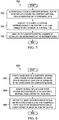
- Method 700 automatically images a composite material, during or after laying down the composite material, using a vision system to form image data (operation 702 ).
- Method 700 identifies, by a computer system, inconsistencies in the composite material visible within the image data in real-time (operation 704 ).
- Method 700 makes, by the computer system, a number of metrology decisions based on the inconsistencies (operation 706 ). Afterwards, the method terminates.
- the computer system makes the number of metrology decisions without input from a human operator.
- the computer system makes the number of metrology decisions in real time.
- the computer system makes the number of metrology decisions in-process.
- making the number of metrology decisions includes sending out a warning when an inconsistency of the inconsistencies identified in the image data violates an inconsistency allowance threshold.
- An inconsistency may violate an inconsistency allowance threshold based on at least one of the inconsistency's size, location, type, or some other property of the inconsistency. For example, the inconsistency may violate the inconsistency allowance threshold when the inconsistency allowance threshold is a size and the inconsistency is larger than the inconsistency allowance threshold.
- an inconsistency may violate an inconsistency allowance threshold when taking into account properties of other inconsistencies.
- an inconsistency may violate an inconsistency allowance threshold based on properties of the group, such as density, spacing, same type, same size, or other properties of the group inconsistencies.
- the inconsistency allowance threshold is a density of inconsistencies, and the location of the inconsistency relative to other inconsistencies creates a density of inconsistencies that violates the inconsistency allowance threshold.
- an inconsistency may violate an inconsistency allowance threshold based on frequency, which takes into account a count of inconsistencies as well as the location, density, type, and shape of the inconsistencies in image data.
- the composite material is part of a component.
- the inconsistency allowance threshold may take into account at least one of a quantity of inconsistencies identified in a prior level of composite material of the component, types of inconsistencies identified in a prior level of composite material of the component, or locations of inconsistencies identified in a prior level of composite material of the component.
- the inconsistency allowance threshold may be raised or lowered depending on the inconsistencies identified in the prior level. For example, if a high density of inconsistencies is present in a location of a prior level of composite material, the allowable density of inconsistencies over this location in the current composite material, expressed as an inconsistency allowance threshold, may be lower than if a high density of inconsistencies was not present in the location. As another example, an allowable quantity of large inconsistencies, expressed as an inconsistency allowance threshold, may be higher if less than a predicted quantity of large inconsistencies were present in a prior level of composite material.
- making the number of metrology decisions includes modifying an inconsistency allowance threshold while imaging the composite material.
- the inconsistency allowance threshold is modified based on properties of the inconsistencies identified in the image data including at least one of locations of the inconsistencies, a quantity of the inconsistencies, a density of the inconsistencies, or a measure of randomness of the inconsistencies.
- a frequency of the inconsistencies may be used. The frequency may take into account the location, density, type, and shape of the inconsistencies in image data. When used, the frequency of inconsistencies in image data may be compared to the frequency of inconsistencies in historical data for other composite layers of the component. For example, increased frequency of inconsistencies in several layers of one portion of the component may violate an inconsistency allowance threshold.
- the inconsistency allowance threshold may be lowered to trigger a warning earlier during the manufacturing process.
- the warning earlier there may be less waste and a lower manufacturing time.
- laying down composite material may be stopped prior to completing a full ply of the composite material.
- a volume of material to be reworked may be reduced, thus reducing waste.
- the additional manufacturing time of completing the ply is not expended.
- an overall quantity of inconsistencies of the inconsistency allowance threshold may be increased so that the warning is not triggered by the dense location of inconsistencies.
- a degree of randomness of inconsistencies detected may be greater than anticipated. When the degree of randomness of inconsistencies is considerably greater than anticipated, the inconsistency allowance threshold may be increased to more closely represent the actual degree of randomness present during inspection.
- the composite material is part of a component, and the inconsistency allowance threshold is modified based on a design of the component.
- the design of the component may include any desirable features of the component, such as thickness, locations of strain, locations associated with electronic components, locations of joints, required strength, contours, complexity of contours, penetrations, or other design features of the component.
- the inconsistency allowance threshold may be lowered for density of inconsistencies in a thinner region of the component.
- the inconsistency allowance threshold By lowering the inconsistency allowance threshold, there is a lower acceptable density in this thinner region of the component than in thicker regions of the component.
- support structures such as fasteners
- the inconsistency allowance threshold may take into account the presence of fastener holes.
- the inconsistency allowance threshold is modified based on historical performance data of other components. For example, the inconsistency allowance threshold for a quantity of large inconsistencies may be lowered based on an estimate of the performance of the current component with the identified inconsistencies. The estimate of the performance is based on performance data, such as strength data, of other components having similar inconsistencies.
- the historical performance data of components having the same design is used to estimate a current performance of the current component based on the identified inconsistencies and modify the inconsistency allowance threshold such that current component meets desired performance characteristics if the current component does not violate the inconsistency allowance threshold.
- the inconsistency allowance threshold may be modified based on modifying the design of the component.
- additional composite levels may be added to the design of the component.
- An inconsistency allowance threshold may take into account thickness of the component.
- An inconsistency allowance threshold may be greater when more material is present.
- an inconsistency allowance threshold may take into account frequency of inconsistencies, pattern of inconsistencies, and thickness of the component. If the thickness of the component changes, the inconsistency allowance threshold may also be modified.
- making the number of metrology decisions includes suggesting the use of additional support structures.
- making the number of metrology decisions may include making recommendations to include a larger quantity of fasteners in a component based on identified inconsistencies.
- Method 800 may be used to inspect a component of aircraft 100 of Figure 1 .
- Method 800 may be used to image composite material 210 of Figure 2 and display inconsistencies in composite material 210 within image data 212 of Figure 2 .
- Method 800 may be implemented within manufacturing environment 300 using vision system 308 and display 310 of Figure 3 .
- Method 800 may produce at least one of view 500 of Figure 5 or image data 604 of Figure 6 .
- Method 800 creates image data of a composite material using a vision system, wherein the image data is created at least one of during or after laying down the composite material (operation 802 ).
- Method 800 identifies, by a computer system, inconsistencies in the composite material visible within the image data in real-time (operation 804 ).
- Method 800 displays the image data on a display in real-time with a width and a length superimposed over each of the inconsistencies that is visible within the image data on the display (operation 806 ). Afterwards, the method terminates.
- each block in the flowcharts or block diagrams may represent a module, a segment, a function, and/or a portion of an operation or step.
- the function or functions noted in the blocks may occur out of the order noted in the figures.
- two blocks shown in succession may be executed substantially concurrently, or the blocks may sometimes be performed in the reverse order, depending upon the functionality involved.
- other blocks may be added, in addition to the illustrated blocks, in a flowchart or block diagram.
- method 700 may further comprise storing data for the inconsistencies in a database, building machine learning datasets and probabilistic information using the database, and using the machine learning datasets and probabilistic information to forecast a quality of a portion of a component containing the composite material.
- the forecast takes into account at least one of historical data for other components, the design of the component, or the inconsistencies identified in the composite material.
- method 700 further comprises displaying the image data in real-time with a width and a length superimposed over each of the inconsistencies that is visible within displayed image data. Displaying the image data in real-time allows operators to monitor the types of inconsistencies, locations of inconsistencies, and size of inconsistencies in real-time.
- method 700 further comprises assigning an inconsistency type, by the computer system, to each of the inconsistencies identified in the image data.
- assigning the inconsistency type additional information about the inconsistencies present on the composite material is provided to the computer system. With greater amounts of information, the computer system may better control and monitor a composite fabrication process. Further, by assigning the inconsistency type, the computer system may be able to diagnose out of tolerance conditions in specific types of materials, specific manufacturing tools, or in specific areas of a manufacturing environment.
- the inconsistencies identified in the image data are measured. Measurements of the inconsistencies may have any desirable tolerance. In some illustrative examples, measuring the inconsistencies identified in the image data comprises measuring the inconsistencies to the nearest ⁇ 0.01 inch. In some illustrative example, measuring the inconsistencies identified in the image data comprises measuring the inconsistencies to the nearest ⁇ 0.10 inch.
- method 800 may further comprise making, by the computer system, number of metrology decisions based on the inconsistencies, historical performance data, and a design of a component wherein the composite material is a part of the component.
- the number of metrology decisions comprises adjusting composite lay down parameters for the composite material or a future ply.
- a metrology decision may be to change at least one of lay down speed, lay down angle, composite compaction pressure, heat applied during lay down, cutting speed, cutting angle for a current or future ply.
- composite lay down parameters of the current ply are changed in real time.
- composite lay down parameters for a composite material are changed as the composite material is being laid down.
- the computer system is configured to analyze the image data and make a decision to change composite lay down parameters independent of a human operator.
- the computer system is configured to analyze the image data and determine if changing composite lay down parameters is desirable in-real time.
- method 800 may further comprise modifying, by the computer system, an inconsistency allowance threshold while imaging the composite material, wherein the inconsistency allowance threshold is modified based on the inconsistencies identified in the image data.
- Data processing system 900 may be used to implement computer system 208 of Figure 2 .
- data processing system 900 includes communications framework 902, which provides communications between processor unit 904, storage devices 906, communications unit 908, input/output unit 910, and display 912.
- communications framework 902 may be implemented as a bus system.
- Processor unit 904 is configured to execute instructions for software to perform a number of operations.
- Processor unit 904 may comprise a number of processors, a multi-processor core, and/or some other suitable type of processor, depending on the implementation.
- processor unit 904 may take the form of a hardware unit, such as a circuit system, an application specific integrated circuit (ASIC), a programmable logic device, or some other suitable type of hardware unit.
- ASIC application specific integrated circuit
- Storage devices 906 may be in communication with processor unit 904 through communications framework 902.
- a storage device also referred to as a computer-readable storage device, is any piece of hardware capable of storing information on a temporary and/or permanent basis. This information may include, but is not limited to, data, a program code, and/or other types of information.
- Memory 914 and persistent storage 916 are examples of storage devices 906.
- Memory 914 may take the form of, for example, a random access memory or some type of volatile or non-volatile storage device.
- Persistent storage 916 may comprise any number of components or devices.
- persistent storage 916 may comprise a hard drive, a flash memory drive, a rewritable optical disk, a rewritable magnetic tape, or some combination of the above.
- the media used by persistent storage 916 may or may not be removable.
- Communications unit 908 allows data processing system 900 to communicate with other data processing systems and/or devices. Communications unit 908 may provide communications using physical and/or wireless communications links.
- Input/output unit 910 allows input to be received from, and output to be sent to other devices connected to data processing system 900.
- input/output unit 910 may allow user input to be received through a keyboard, a mouse, and/or some other type of input device.
- input/output unit 910 may allow output to be sent to a printer connected to data processing system 900.
- Display 912 is configured to display information to a user.
- Display 912 may comprise, for example, without limitation, a monitor, a touch screen, a laser display, a holographic display, a virtual display device, and/or some other type of display device.
- processor unit 904 may perform the processes of the different illustrative embodiments using computer-implemented instructions. These instructions may be referred to as a program code, a computer-usable program code, or a computer-readable program code, and may be read and executed by one or more processors in processor unit 904.
- program code 918 is located in a functional form on computer-readable media 920, which is selectively removable, and may be loaded onto or transferred to data processing system 900 for execution by processor unit 904.
- Program code 918 and computer-readable media 920 together form computer program product 922.
- computer-readable media 920 may be computer-readable storage media 924 or computer-readable signal media 926.
- Computer-readable storage media 924 is a physical or tangible storage device used to store program code 918, rather than a medium that propagates or transmits program code 918.
- Computer-readable storage media 924 may be, for example, without limitation, an optical or magnetic disk, or a persistent storage device that is connected to data processing system 900.
- program code 918 may be transferred to data processing system 900 using computer-readable signal media 926.
- Computer-readable signal media 926 may be, for example, a propagated data signal containing program code 918. This data signal may be an electromagnetic signal, an optical signal, and/or some other type of signal that can be transmitted over physical and/or wireless communications links.
- data processing system 900 in Figure 9 is not meant to provide architectural limitations to the manner in which the illustrative embodiments may be implemented.
- the different illustrative embodiments may be implemented in a data processing system that includes components, in addition to or in place of those illustrated, for data processing system 900. Further, components shown in Figure 9 may be varied from the illustrative examples shown.
- aircraft manufacturing and service method 1000 may be described in the context of aircraft manufacturing and service method 1000 as shown in Figure 10 and aircraft 1100 as shown in Figure 11 .
- Figure 10 an illustration of an aircraft manufacturing and service method is depicted in accordance with an illustrative embodiment.
- aircraft manufacturing and service method 1000 may include specification and design 1002 of aircraft 1100 in Figure 11 and material procurement 1004.
- aircraft 1100 During production, component and subassembly manufacturing 1006 and system integration 1008 of aircraft 1100 takes place. Thereafter, aircraft 1100 may go through certification and delivery 1010 in order to be placed in service 1012. While in service 1012 by a customer, aircraft 1100 is scheduled for routine maintenance and service 1014, which may include modification, reconfiguration, refurbishment, and other maintenance or service.
- Each of the processes of aircraft manufacturing and service method 1000 may be performed or carried out by a system integrator, a third party, and/or an operator.
- the operator may be a customer.
- a system integrator may include, without limitation, any number of aircraft manufacturers and major-system subcontractors
- a third party may include, without limitation, any number of vendors, subcontractors, and suppliers
- an operator may be an airline, a leasing company, a military entity, a service organization, and so on.
- aircraft 1100 is produced by aircraft manufacturing and service method 1000 of Figure 10 and may include airframe 1102 with plurality of systems 1104 and interior 1106.
- systems 1104 include one or more of propulsion system 1108, electrical system 1110, hydraulic system 1112, and environmental system 1114. Any number of other systems may be included.
- propulsion system 1108, electrical system 1110, hydraulic system 1112, and environmental system 1114 Any number of other systems may be included.
- an aerospace example is shown, different illustrative embodiments may be applied to other industries, such as the automotive industry.
- Apparatuses and methods embodied herein may be employed during at least one of the stages of aircraft manufacturing and service method 1000.
- the phrase "at least one of,” when used with a list of items, means different combinations of one or more of the listed items may be used, and only one of each item in the list may be needed. In other words, “at least one of” means any combination of items and number of items may be used from the list, but not all of the items in the list are required.
- the item may be a particular object, a thing, or a category.
- “at least one of item A, item B, or item C” may include, without limitation, item A, item A and item B, or item B. This example also may include item A, item B, and item C or item B and item C. Of course, any combination of these items may be present. In other examples, "at least one of” may be, for example, without limitation, two of item A, one of item B, and ten of item C; four of item B and seven of item C; or other suitable combinations.
- system 202 of Figure 2 may be used during component and subassembly manufacturing 1006 to inspect composite material 210 of Figure 2 .
- Image data 212 of Figure 2 may be formed during component and subassembly manufacturing 1006 using method 700 of Figure 7 .
- System 202 of Figure 2 may be used to inspect any desirable portion of airframe 1102 or interior 1106.
- any desirable portion of airframe 1102 or interior 1106 may be inspected using system 202 of Figure 2 during system integration 1008 of aircraft 1100.
- Component 224 of Figure 2 to be inspected using system 202 may be replacement components inspected during maintenance and service 1014 of Figure 10 .
- replacement components of airframe 1102 or interior 1106 may be inspected using system 202 of Figure 2 .
- the replacement components may be inspected using method 700 of Figure 7 or method 800 of Figure 8 during maintenance and service 1014 of Figure 10 .
- the illustrative embodiments present an in-process economical intelligent camera system using computer vision, video data analytics/tools, and machine learning.
- a single non-intrusive system recognizes, identifies, and records inconsistencies during the composite lamination process for comparison to inconsistency allowances.
- this system can be taught to modify data collection as allowances for inconsistencies are revised based on improved process performance.
- the illustrative examples may eliminate a ply sequence by ply sequence walk around a part and recording findings for later evaluation by a manufacturing technician. Elimination of a ply sequence by ply sequence walk around would result in labor and flow-time reduction.
Landscapes
- Engineering & Computer Science (AREA)
- Physics & Mathematics (AREA)
- General Physics & Mathematics (AREA)
- Robotics (AREA)
- Chemical & Material Sciences (AREA)
- Mechanical Engineering (AREA)
- Quality & Reliability (AREA)
- Composite Materials (AREA)
- Automation & Control Theory (AREA)
- General Engineering & Computer Science (AREA)
- Manufacturing & Machinery (AREA)
- Computer Vision & Pattern Recognition (AREA)
- Theoretical Computer Science (AREA)
- Immunology (AREA)
- Health & Medical Sciences (AREA)
- Life Sciences & Earth Sciences (AREA)
- Analytical Chemistry (AREA)
- Biochemistry (AREA)
- General Health & Medical Sciences (AREA)
- Pathology (AREA)
- Signal Processing (AREA)
- Investigating Materials By The Use Of Optical Means Adapted For Particular Applications (AREA)
- Image Analysis (AREA)
- Length Measuring Devices By Optical Means (AREA)
- General Factory Administration (AREA)
- Moulding By Coating Moulds (AREA)
- Image Processing (AREA)
Applications Claiming Priority (1)
| Application Number | Priority Date | Filing Date | Title |
|---|---|---|---|
| US15/581,432 US10737446B2 (en) | 2017-04-28 | 2017-04-28 | Process control of a composite fabrication process |
Publications (2)
| Publication Number | Publication Date |
|---|---|
| EP3396484A1 true EP3396484A1 (de) | 2018-10-31 |
| EP3396484B1 EP3396484B1 (de) | 2022-09-28 |
Family
ID=61965756
Family Applications (1)
| Application Number | Title | Priority Date | Filing Date |
|---|---|---|---|
| EP18166494.7A Active EP3396484B1 (de) | 2017-04-28 | 2018-04-10 | Prozesssteuerung eines verbundfertigungsprozesses |
Country Status (8)
| Country | Link |
|---|---|
| US (1) | US10737446B2 (de) |
| EP (1) | EP3396484B1 (de) |
| JP (1) | JP7190815B2 (de) |
| CN (1) | CN108805857B (de) |
| BR (1) | BR102018006019B1 (de) |
| CA (1) | CA2995068C (de) |
| ES (1) | ES2933989T3 (de) |
| PT (1) | PT3396484T (de) |
Cited By (2)
| Publication number | Priority date | Publication date | Assignee | Title |
|---|---|---|---|---|
| DE102018124080A1 (de) * | 2018-09-28 | 2020-04-02 | Deutsches Zentrum für Luft- und Raumfahrt e.V. | Verfahren und Anlage zur Herstellung eines Faserlaminates aus einem Fasermaterial eines Faserverbundwerkstoffes zur Herstellung eines Faserverbundbauteils |
| EP3754605A1 (de) * | 2019-06-20 | 2020-12-23 | Deutsches Zentrum für Luft- und Raumfahrt e.V. | Verfahren und vorrichtung zum ermitteln von fehlstellen an einem fasermaterial sowie faserlegeanlage hierzu |
Families Citing this family (10)
| Publication number | Priority date | Publication date | Assignee | Title |
|---|---|---|---|---|
| US9651680B2 (en) * | 2012-11-15 | 2017-05-16 | Bwxt Technical Services Group, Inc. | Gamma ray spectroscopy monitoring method and apparatus |
| US11225039B2 (en) * | 2018-06-08 | 2022-01-18 | Aurora Flight Sciences Corporation | Systems and methods to automate composite manufacturing quality checks |
| US20200023537A1 (en) * | 2018-07-20 | 2020-01-23 | Aurora Flight Sciences Corporation | Composite manufacturing system and method |
| US12443173B2 (en) | 2021-10-12 | 2025-10-14 | Royal Engineered Composites, Inc. | Systems and methods for composite fabrication with AI quality control modules |
| ES2957904B2 (es) | 2022-06-27 | 2026-03-11 | Airbus Operations Slu | Sistema de detección de anomalías en la colocación automática de composites durante la fabricación de elementos estructurales |
| US20240153063A1 (en) * | 2022-07-08 | 2024-05-09 | The Boeing Company | Real Time Inconsistency Detection During Composite Material Manufacturing |
| US12422831B2 (en) | 2022-07-08 | 2025-09-23 | The Boeing Company | Property prediction for unconsolidated composite materials |
| US12566132B2 (en) | 2022-07-08 | 2026-03-03 | The Boeing Company | Real time contaminants identification during composite material manufacturing via non-contact chemical sensing |
| JP2024144253A (ja) * | 2023-03-30 | 2024-10-11 | ザ・ボーイング・カンパニー | 非接触化学センシングによる複合材料製造中のリアルタイムの汚染物質同定 |
| CN116214523B (zh) * | 2023-05-06 | 2023-07-07 | 深圳市中科云科技开发有限公司 | 工业机器人及其控制方法、装置 |
Citations (6)
| Publication number | Priority date | Publication date | Assignee | Title |
|---|---|---|---|---|
| US5562788A (en) * | 1994-09-20 | 1996-10-08 | The Boeing Company | Composite material laser flaw detection |
| WO2005036634A2 (en) * | 2003-08-20 | 2005-04-21 | Kla-Tencor Technologies Corporation | Interactive threshold tuning in an inspection system |
| WO2010132998A1 (en) * | 2009-05-22 | 2010-11-25 | Telere Technologies Inc . | Process for improving the production of photovoltaic products |
| EP2730914A1 (de) * | 2011-10-28 | 2014-05-14 | Toray Industries, Inc. | Verfahren zur herstellung von prepreg |
| EP3007022A2 (de) * | 2014-10-06 | 2016-04-13 | The Boeing Company | System und verfahren zur inspektion eines verbundteils während der herstellung |
| US20170030886A1 (en) * | 2015-07-31 | 2017-02-02 | Airbus Defence and Space GmbH | Probabilistic defect detection in laid fiber ribbons |
Family Cites Families (12)
| Publication number | Priority date | Publication date | Assignee | Title |
|---|---|---|---|---|
| US6064429A (en) | 1997-08-18 | 2000-05-16 | Mcdonnell Douglas Corporation | Foreign object video detection and alert system and method |
| JP3566589B2 (ja) * | 1998-07-28 | 2004-09-15 | 株式会社日立製作所 | 欠陥検査装置およびその方法 |
| US7236625B2 (en) | 2003-07-28 | 2007-06-26 | The Boeing Company | Systems and method for identifying foreign objects and debris (FOD) and defects during fabrication of a composite structure |
| US8934702B2 (en) * | 2003-12-02 | 2015-01-13 | The Boeing Company | System and method for determining cumulative tow gap width |
| US8068659B2 (en) | 2003-12-02 | 2011-11-29 | The Boeing Company | Method and system for determining cumulative foreign object characteristics during fabrication of a composite structure |
| US7454053B2 (en) * | 2004-10-29 | 2008-11-18 | Mitutoyo Corporation | System and method for automatically recovering video tools in a vision system |
| US7424902B2 (en) | 2004-11-24 | 2008-09-16 | The Boeing Company | In-process vision detection of flaw and FOD characteristics |
| US20060108048A1 (en) | 2004-11-24 | 2006-05-25 | The Boeing Company | In-process vision detection of flaws and fod by back field illumination |
| CN101074877A (zh) * | 2007-06-14 | 2007-11-21 | 南京航空航天大学 | 复合材料铺放质量视频检测系统及间隙检测方法 |
| GB201008139D0 (en) * | 2010-05-14 | 2010-06-30 | Paramata Ltd | Sensing system and method |
| CN103512906A (zh) * | 2013-10-17 | 2014-01-15 | 航天海鹰(镇江)特种材料有限公司 | 航空复合材料蜂窝结构件x射线cr检测方法 |
| US9618459B2 (en) * | 2015-05-18 | 2017-04-11 | Flightware, Inc. | Systems and methods for automated composite layup quality assurance |
-
2017
- 2017-04-28 US US15/581,432 patent/US10737446B2/en active Active
-
2018
- 2018-02-13 CA CA2995068A patent/CA2995068C/en active Active
- 2018-02-15 JP JP2018024891A patent/JP7190815B2/ja active Active
- 2018-03-26 BR BR102018006019-8A patent/BR102018006019B1/pt active IP Right Grant
- 2018-04-03 CN CN201810289871.8A patent/CN108805857B/zh active Active
- 2018-04-10 PT PT181664947T patent/PT3396484T/pt unknown
- 2018-04-10 ES ES18166494T patent/ES2933989T3/es active Active
- 2018-04-10 EP EP18166494.7A patent/EP3396484B1/de active Active
Patent Citations (6)
| Publication number | Priority date | Publication date | Assignee | Title |
|---|---|---|---|---|
| US5562788A (en) * | 1994-09-20 | 1996-10-08 | The Boeing Company | Composite material laser flaw detection |
| WO2005036634A2 (en) * | 2003-08-20 | 2005-04-21 | Kla-Tencor Technologies Corporation | Interactive threshold tuning in an inspection system |
| WO2010132998A1 (en) * | 2009-05-22 | 2010-11-25 | Telere Technologies Inc . | Process for improving the production of photovoltaic products |
| EP2730914A1 (de) * | 2011-10-28 | 2014-05-14 | Toray Industries, Inc. | Verfahren zur herstellung von prepreg |
| EP3007022A2 (de) * | 2014-10-06 | 2016-04-13 | The Boeing Company | System und verfahren zur inspektion eines verbundteils während der herstellung |
| US20170030886A1 (en) * | 2015-07-31 | 2017-02-02 | Airbus Defence and Space GmbH | Probabilistic defect detection in laid fiber ribbons |
Cited By (3)
| Publication number | Priority date | Publication date | Assignee | Title |
|---|---|---|---|---|
| DE102018124080A1 (de) * | 2018-09-28 | 2020-04-02 | Deutsches Zentrum für Luft- und Raumfahrt e.V. | Verfahren und Anlage zur Herstellung eines Faserlaminates aus einem Fasermaterial eines Faserverbundwerkstoffes zur Herstellung eines Faserverbundbauteils |
| DE102018124080B4 (de) * | 2018-09-28 | 2021-07-01 | Deutsches Zentrum für Luft- und Raumfahrt e.V. | Verfahren und Anlage zur Herstellung eines Faserlaminates aus einem Fasermaterial eines Faserverbundwerkstoffes zur Herstellung eines Faserverbundbauteils |
| EP3754605A1 (de) * | 2019-06-20 | 2020-12-23 | Deutsches Zentrum für Luft- und Raumfahrt e.V. | Verfahren und vorrichtung zum ermitteln von fehlstellen an einem fasermaterial sowie faserlegeanlage hierzu |
Also Published As
| Publication number | Publication date |
|---|---|
| CN108805857B (zh) | 2023-08-25 |
| US10737446B2 (en) | 2020-08-11 |
| JP7190815B2 (ja) | 2022-12-16 |
| CA2995068A1 (en) | 2018-10-28 |
| BR102018006019B1 (pt) | 2023-01-31 |
| EP3396484B1 (de) | 2022-09-28 |
| US20180311914A1 (en) | 2018-11-01 |
| CN108805857A (zh) | 2018-11-13 |
| ES2933989T3 (es) | 2023-02-15 |
| PT3396484T (pt) | 2022-10-06 |
| JP2018187916A (ja) | 2018-11-29 |
| BR102018006019A2 (pt) | 2019-02-26 |
| CA2995068C (en) | 2022-07-12 |
Similar Documents
| Publication | Publication Date | Title |
|---|---|---|
| CA2995068C (en) | Process control of a composite fabrication process | |
| CA2883726C (en) | Composite inspection and structural check of multiple layers | |
| Zambal et al. | A digital twin for composite parts manufacturing: Effects of defects analysis based on manufacturing data | |
| US10197392B2 (en) | Automated resin ridge reduction system | |
| JP2015172576A5 (ja) | 複合アイテムの検査方法及びシステム | |
| EP3995297A1 (de) | Verfahren und vorrichtung zur steuerung des kontakts von kompositseilen | |
| EP3367195B1 (de) | Identifizieren eines wegs für den zustand einer montagevalidierung | |
| US9720398B2 (en) | Method and apparatus for customizing tool paths for aircraft parts | |
| EP2664548B1 (de) | Schadensbeurteilungssystem und Betriebsverfahren dafür | |
| EP2562090B1 (de) | Systeme und Verfahren zur automatisierten Lokalisierung und Einstufung von Fehlern | |
| CN109458962B (zh) | 自动化铆钉测量系统 | |
| US9038470B1 (en) | Porosity inspection system for composite structures | |
| US9360459B2 (en) | Porosity inspection system for composite structure with non-parallel surfaces | |
| EP4016073B1 (de) | Erkennung von strukturellen inkonsistenzen mit abstandsdaten | |
| US12266090B2 (en) | Systems and methods for detecting defects in powder manufactured components | |
| EP4450265B1 (de) | Echtzeitinkonsistenzerkennung während der herstellung von verbundmaterial |
Legal Events
| Date | Code | Title | Description |
|---|---|---|---|
| PUAI | Public reference made under article 153(3) epc to a published international application that has entered the european phase |
Free format text: ORIGINAL CODE: 0009012 |
|
| STAA | Information on the status of an ep patent application or granted ep patent |
Free format text: STATUS: REQUEST FOR EXAMINATION WAS MADE |
|
| 17P | Request for examination filed |
Effective date: 20180410 |
|
| AK | Designated contracting states |
Kind code of ref document: A1 Designated state(s): AL AT BE BG CH CY CZ DE DK EE ES FI FR GB GR HR HU IE IS IT LI LT LU LV MC MK MT NL NO PL PT RO RS SE SI SK SM TR |
|
| AX | Request for extension of the european patent |
Extension state: BA ME |
|
| STAA | Information on the status of an ep patent application or granted ep patent |
Free format text: STATUS: EXAMINATION IS IN PROGRESS |
|
| 17Q | First examination report despatched |
Effective date: 20201029 |
|
| RIC1 | Information provided on ipc code assigned before grant |
Ipc: G05B 19/42 20060101ALN20211012BHEP Ipc: B25J 9/16 20060101ALN20211012BHEP Ipc: B29C 70/38 20060101ALI20211012BHEP Ipc: G05B 19/418 20060101AFI20211012BHEP |
|
| GRAP | Despatch of communication of intention to grant a patent |
Free format text: ORIGINAL CODE: EPIDOSNIGR1 |
|
| STAA | Information on the status of an ep patent application or granted ep patent |
Free format text: STATUS: GRANT OF PATENT IS INTENDED |
|
| RIC1 | Information provided on ipc code assigned before grant |
Ipc: G05B 19/42 20060101ALN20211028BHEP Ipc: B25J 9/16 20060101ALN20211028BHEP Ipc: B29C 70/38 20060101ALI20211028BHEP Ipc: G05B 19/418 20060101AFI20211028BHEP |
|
| INTG | Intention to grant announced |
Effective date: 20211124 |
|
| RIC1 | Information provided on ipc code assigned before grant |
Ipc: G05B 19/42 20060101ALN20211115BHEP Ipc: B25J 9/16 20060101ALN20211115BHEP Ipc: B29C 70/38 20060101ALI20211115BHEP Ipc: G05B 19/418 20060101AFI20211115BHEP |
|
| GRAJ | Information related to disapproval of communication of intention to grant by the applicant or resumption of examination proceedings by the epo deleted |
Free format text: ORIGINAL CODE: EPIDOSDIGR1 |
|
| STAA | Information on the status of an ep patent application or granted ep patent |
Free format text: STATUS: EXAMINATION IS IN PROGRESS |
|
| INTC | Intention to grant announced (deleted) | ||
| RIC1 | Information provided on ipc code assigned before grant |
Ipc: G05B 19/42 20060101ALN20220328BHEP Ipc: B25J 9/16 20060101ALN20220328BHEP Ipc: B29C 70/38 20060101ALI20220328BHEP Ipc: G05B 19/418 20060101AFI20220328BHEP |
|
| GRAP | Despatch of communication of intention to grant a patent |
Free format text: ORIGINAL CODE: EPIDOSNIGR1 |
|
| STAA | Information on the status of an ep patent application or granted ep patent |
Free format text: STATUS: GRANT OF PATENT IS INTENDED |
|
| INTG | Intention to grant announced |
Effective date: 20220530 |
|
| RIC1 | Information provided on ipc code assigned before grant |
Ipc: G05B 19/42 20060101ALN20220516BHEP Ipc: B25J 9/16 20060101ALN20220516BHEP Ipc: B29C 70/38 20060101ALI20220516BHEP Ipc: G05B 19/418 20060101AFI20220516BHEP |
|
| GRAS | Grant fee paid |
Free format text: ORIGINAL CODE: EPIDOSNIGR3 |
|
| GRAA | (expected) grant |
Free format text: ORIGINAL CODE: 0009210 |
|
| STAA | Information on the status of an ep patent application or granted ep patent |
Free format text: STATUS: THE PATENT HAS BEEN GRANTED |
|
| AK | Designated contracting states |
Kind code of ref document: B1 Designated state(s): AL AT BE BG CH CY CZ DE DK EE ES FI FR GB GR HR HU IE IS IT LI LT LU LV MC MK MT NL NO PL PT RO RS SE SI SK SM TR |
|
| REG | Reference to a national code |
Ref country code: GB Ref legal event code: FG4D |
|
| REG | Reference to a national code |
Ref country code: CH Ref legal event code: EP |
|
| REG | Reference to a national code |
Ref country code: PT Ref legal event code: SC4A Ref document number: 3396484 Country of ref document: PT Date of ref document: 20221006 Kind code of ref document: T Free format text: AVAILABILITY OF NATIONAL TRANSLATION Effective date: 20220930 |
|
| REG | Reference to a national code |
Ref country code: AT Ref legal event code: REF Ref document number: 1521641 Country of ref document: AT Kind code of ref document: T Effective date: 20221015 |
|
| REG | Reference to a national code |
Ref country code: DE Ref legal event code: R096 Ref document number: 602018041039 Country of ref document: DE |
|
| REG | Reference to a national code |
Ref country code: IE Ref legal event code: FG4D |
|
| REG | Reference to a national code |
Ref country code: SE Ref legal event code: TRGR |
|
| REG | Reference to a national code |
Ref country code: LT Ref legal event code: MG9D |
|
| PG25 | Lapsed in a contracting state [announced via postgrant information from national office to epo] |
Ref country code: RS Free format text: LAPSE BECAUSE OF FAILURE TO SUBMIT A TRANSLATION OF THE DESCRIPTION OR TO PAY THE FEE WITHIN THE PRESCRIBED TIME-LIMIT Effective date: 20220928 Ref country code: NO Free format text: LAPSE BECAUSE OF FAILURE TO SUBMIT A TRANSLATION OF THE DESCRIPTION OR TO PAY THE FEE WITHIN THE PRESCRIBED TIME-LIMIT Effective date: 20221228 Ref country code: LV Free format text: LAPSE BECAUSE OF FAILURE TO SUBMIT A TRANSLATION OF THE DESCRIPTION OR TO PAY THE FEE WITHIN THE PRESCRIBED TIME-LIMIT Effective date: 20220928 Ref country code: LT Free format text: LAPSE BECAUSE OF FAILURE TO SUBMIT A TRANSLATION OF THE DESCRIPTION OR TO PAY THE FEE WITHIN THE PRESCRIBED TIME-LIMIT Effective date: 20220928 Ref country code: FI Free format text: LAPSE BECAUSE OF FAILURE TO SUBMIT A TRANSLATION OF THE DESCRIPTION OR TO PAY THE FEE WITHIN THE PRESCRIBED TIME-LIMIT Effective date: 20220928 |
|
| REG | Reference to a national code |
Ref country code: NL Ref legal event code: MP Effective date: 20220928 |
|
| REG | Reference to a national code |
Ref country code: AT Ref legal event code: MK05 Ref document number: 1521641 Country of ref document: AT Kind code of ref document: T Effective date: 20220928 Ref country code: ES Ref legal event code: FG2A Ref document number: 2933989 Country of ref document: ES Kind code of ref document: T3 Effective date: 20230215 |
|
| PG25 | Lapsed in a contracting state [announced via postgrant information from national office to epo] |
Ref country code: HR Free format text: LAPSE BECAUSE OF FAILURE TO SUBMIT A TRANSLATION OF THE DESCRIPTION OR TO PAY THE FEE WITHIN THE PRESCRIBED TIME-LIMIT Effective date: 20220928 Ref country code: GR Free format text: LAPSE BECAUSE OF FAILURE TO SUBMIT A TRANSLATION OF THE DESCRIPTION OR TO PAY THE FEE WITHIN THE PRESCRIBED TIME-LIMIT Effective date: 20221229 |
|
| RAP4 | Party data changed (patent owner data changed or rights of a patent transferred) |
Owner name: THE BOEING COMPANY |
|
| PG25 | Lapsed in a contracting state [announced via postgrant information from national office to epo] |
Ref country code: SM Free format text: LAPSE BECAUSE OF FAILURE TO SUBMIT A TRANSLATION OF THE DESCRIPTION OR TO PAY THE FEE WITHIN THE PRESCRIBED TIME-LIMIT Effective date: 20220928 Ref country code: RO Free format text: LAPSE BECAUSE OF FAILURE TO SUBMIT A TRANSLATION OF THE DESCRIPTION OR TO PAY THE FEE WITHIN THE PRESCRIBED TIME-LIMIT Effective date: 20220928 Ref country code: CZ Free format text: LAPSE BECAUSE OF FAILURE TO SUBMIT A TRANSLATION OF THE DESCRIPTION OR TO PAY THE FEE WITHIN THE PRESCRIBED TIME-LIMIT Effective date: 20220928 Ref country code: AT Free format text: LAPSE BECAUSE OF FAILURE TO SUBMIT A TRANSLATION OF THE DESCRIPTION OR TO PAY THE FEE WITHIN THE PRESCRIBED TIME-LIMIT Effective date: 20220928 |
|
| PG25 | Lapsed in a contracting state [announced via postgrant information from national office to epo] |
Ref country code: SK Free format text: LAPSE BECAUSE OF FAILURE TO SUBMIT A TRANSLATION OF THE DESCRIPTION OR TO PAY THE FEE WITHIN THE PRESCRIBED TIME-LIMIT Effective date: 20220928 Ref country code: PL Free format text: LAPSE BECAUSE OF FAILURE TO SUBMIT A TRANSLATION OF THE DESCRIPTION OR TO PAY THE FEE WITHIN THE PRESCRIBED TIME-LIMIT Effective date: 20220928 Ref country code: IS Free format text: LAPSE BECAUSE OF FAILURE TO SUBMIT A TRANSLATION OF THE DESCRIPTION OR TO PAY THE FEE WITHIN THE PRESCRIBED TIME-LIMIT Effective date: 20230128 Ref country code: EE Free format text: LAPSE BECAUSE OF FAILURE TO SUBMIT A TRANSLATION OF THE DESCRIPTION OR TO PAY THE FEE WITHIN THE PRESCRIBED TIME-LIMIT Effective date: 20220928 |
|
| P01 | Opt-out of the competence of the unified patent court (upc) registered |
Effective date: 20230516 |
|
| REG | Reference to a national code |
Ref country code: DE Ref legal event code: R097 Ref document number: 602018041039 Country of ref document: DE |
|
| PG25 | Lapsed in a contracting state [announced via postgrant information from national office to epo] |
Ref country code: NL Free format text: LAPSE BECAUSE OF FAILURE TO SUBMIT A TRANSLATION OF THE DESCRIPTION OR TO PAY THE FEE WITHIN THE PRESCRIBED TIME-LIMIT Effective date: 20220928 Ref country code: AL Free format text: LAPSE BECAUSE OF FAILURE TO SUBMIT A TRANSLATION OF THE DESCRIPTION OR TO PAY THE FEE WITHIN THE PRESCRIBED TIME-LIMIT Effective date: 20220928 |
|
| PG25 | Lapsed in a contracting state [announced via postgrant information from national office to epo] |
Ref country code: DK Free format text: LAPSE BECAUSE OF FAILURE TO SUBMIT A TRANSLATION OF THE DESCRIPTION OR TO PAY THE FEE WITHIN THE PRESCRIBED TIME-LIMIT Effective date: 20220928 |
|
| PLBE | No opposition filed within time limit |
Free format text: ORIGINAL CODE: 0009261 |
|
| STAA | Information on the status of an ep patent application or granted ep patent |
Free format text: STATUS: NO OPPOSITION FILED WITHIN TIME LIMIT |
|
| 26N | No opposition filed |
Effective date: 20230629 |
|
| PG25 | Lapsed in a contracting state [announced via postgrant information from national office to epo] |
Ref country code: SI Free format text: LAPSE BECAUSE OF FAILURE TO SUBMIT A TRANSLATION OF THE DESCRIPTION OR TO PAY THE FEE WITHIN THE PRESCRIBED TIME-LIMIT Effective date: 20220928 |
|
| REG | Reference to a national code |
Ref country code: CH Ref legal event code: PL |
|
| PG25 | Lapsed in a contracting state [announced via postgrant information from national office to epo] |
Ref country code: LU Free format text: LAPSE BECAUSE OF NON-PAYMENT OF DUE FEES Effective date: 20230410 |
|
| REG | Reference to a national code |
Ref country code: BE Ref legal event code: MM Effective date: 20230430 |
|
| PG25 | Lapsed in a contracting state [announced via postgrant information from national office to epo] |
Ref country code: MC Free format text: LAPSE BECAUSE OF FAILURE TO SUBMIT A TRANSLATION OF THE DESCRIPTION OR TO PAY THE FEE WITHIN THE PRESCRIBED TIME-LIMIT Effective date: 20220928 |
|
| PG25 | Lapsed in a contracting state [announced via postgrant information from national office to epo] |
Ref country code: MC Free format text: LAPSE BECAUSE OF FAILURE TO SUBMIT A TRANSLATION OF THE DESCRIPTION OR TO PAY THE FEE WITHIN THE PRESCRIBED TIME-LIMIT Effective date: 20220928 Ref country code: LI Free format text: LAPSE BECAUSE OF NON-PAYMENT OF DUE FEES Effective date: 20230430 Ref country code: CH Free format text: LAPSE BECAUSE OF NON-PAYMENT OF DUE FEES Effective date: 20230430 |
|
| REG | Reference to a national code |
Ref country code: IE Ref legal event code: MM4A |
|
| PG25 | Lapsed in a contracting state [announced via postgrant information from national office to epo] |
Ref country code: BE Free format text: LAPSE BECAUSE OF NON-PAYMENT OF DUE FEES Effective date: 20230430 |
|
| PG25 | Lapsed in a contracting state [announced via postgrant information from national office to epo] |
Ref country code: IE Free format text: LAPSE BECAUSE OF NON-PAYMENT OF DUE FEES Effective date: 20230410 |
|
| PG25 | Lapsed in a contracting state [announced via postgrant information from national office to epo] |
Ref country code: IE Free format text: LAPSE BECAUSE OF NON-PAYMENT OF DUE FEES Effective date: 20230410 |
|
| PG25 | Lapsed in a contracting state [announced via postgrant information from national office to epo] |
Ref country code: BG Free format text: LAPSE BECAUSE OF FAILURE TO SUBMIT A TRANSLATION OF THE DESCRIPTION OR TO PAY THE FEE WITHIN THE PRESCRIBED TIME-LIMIT Effective date: 20220928 |
|
| PG25 | Lapsed in a contracting state [announced via postgrant information from national office to epo] |
Ref country code: BG Free format text: LAPSE BECAUSE OF FAILURE TO SUBMIT A TRANSLATION OF THE DESCRIPTION OR TO PAY THE FEE WITHIN THE PRESCRIBED TIME-LIMIT Effective date: 20220928 |
|
| PGFP | Annual fee paid to national office [announced via postgrant information from national office to epo] |
Ref country code: DE Payment date: 20250429 Year of fee payment: 8 |
|
| PGFP | Annual fee paid to national office [announced via postgrant information from national office to epo] |
Ref country code: ES Payment date: 20250505 Year of fee payment: 8 Ref country code: GB Payment date: 20250428 Year of fee payment: 8 |
|
| PGFP | Annual fee paid to national office [announced via postgrant information from national office to epo] |
Ref country code: IT Payment date: 20250422 Year of fee payment: 8 |
|
| PGFP | Annual fee paid to national office [announced via postgrant information from national office to epo] |
Ref country code: FR Payment date: 20250425 Year of fee payment: 8 |
|
| PG25 | Lapsed in a contracting state [announced via postgrant information from national office to epo] |
Ref country code: CY Free format text: LAPSE BECAUSE OF FAILURE TO SUBMIT A TRANSLATION OF THE DESCRIPTION OR TO PAY THE FEE WITHIN THE PRESCRIBED TIME-LIMIT; INVALID AB INITIO Effective date: 20180410 |
|
| PGFP | Annual fee paid to national office [announced via postgrant information from national office to epo] |
Ref country code: SE Payment date: 20250430 Year of fee payment: 8 |
|
| PG25 | Lapsed in a contracting state [announced via postgrant information from national office to epo] |
Ref country code: HU Free format text: LAPSE BECAUSE OF FAILURE TO SUBMIT A TRANSLATION OF THE DESCRIPTION OR TO PAY THE FEE WITHIN THE PRESCRIBED TIME-LIMIT; INVALID AB INITIO Effective date: 20180410 |
|
| PG25 | Lapsed in a contracting state [announced via postgrant information from national office to epo] |
Ref country code: TR Free format text: LAPSE BECAUSE OF FAILURE TO SUBMIT A TRANSLATION OF THE DESCRIPTION OR TO PAY THE FEE WITHIN THE PRESCRIBED TIME-LIMIT Effective date: 20220928 |
|
| PGFP | Annual fee paid to national office [announced via postgrant information from national office to epo] |
Ref country code: PT Payment date: 20260323 Year of fee payment: 9 |