EP3396351A1 - Device, system and method for directly sampling a liquid of a tank - Google Patents
Device, system and method for directly sampling a liquid of a tank Download PDFInfo
- Publication number
- EP3396351A1 EP3396351A1 EP17000716.5A EP17000716A EP3396351A1 EP 3396351 A1 EP3396351 A1 EP 3396351A1 EP 17000716 A EP17000716 A EP 17000716A EP 3396351 A1 EP3396351 A1 EP 3396351A1
- Authority
- EP
- European Patent Office
- Prior art keywords
- liquid
- tank
- sampling device
- main
- direct
- Prior art date
- Legal status (The legal status is an assumption and is not a legal conclusion. Google has not performed a legal analysis and makes no representation as to the accuracy of the status listed.)
- Granted
Links
- 239000007788 liquid Substances 0.000 title claims abstract description 155
- 238000005070 sampling Methods 0.000 title claims abstract description 59
- 238000000034 method Methods 0.000 title description 11
- 238000012856 packing Methods 0.000 claims abstract description 40
- NINIDFKCEFEMDL-UHFFFAOYSA-N Sulfur Chemical compound [S] NINIDFKCEFEMDL-UHFFFAOYSA-N 0.000 claims abstract description 9
- 239000005864 Sulphur Substances 0.000 claims abstract description 9
- 230000008878 coupling Effects 0.000 claims abstract description 3
- 238000010168 coupling process Methods 0.000 claims abstract description 3
- 238000005859 coupling reaction Methods 0.000 claims abstract description 3
- IJGRMHOSHXDMSA-UHFFFAOYSA-N Atomic nitrogen Chemical compound N#N IJGRMHOSHXDMSA-UHFFFAOYSA-N 0.000 claims description 6
- 238000009826 distribution Methods 0.000 claims description 6
- 235000015073 liquid stocks Nutrition 0.000 claims description 4
- 238000010926 purge Methods 0.000 claims description 4
- 229910052757 nitrogen Inorganic materials 0.000 claims description 3
- 238000011144 upstream manufacturing Methods 0.000 claims description 3
- 238000005406 washing Methods 0.000 description 12
- 241000196324 Embryophyta Species 0.000 description 11
- 239000007789 gas Substances 0.000 description 10
- 239000000047 product Substances 0.000 description 9
- 239000003921 oil Substances 0.000 description 7
- 235000019198 oils Nutrition 0.000 description 7
- 238000005259 measurement Methods 0.000 description 6
- 238000012544 monitoring process Methods 0.000 description 5
- 238000004458 analytical method Methods 0.000 description 4
- 230000000694 effects Effects 0.000 description 4
- 238000005086 pumping Methods 0.000 description 4
- UHOVQNZJYSORNB-UHFFFAOYSA-N Benzene Chemical compound C1=CC=CC=C1 UHOVQNZJYSORNB-UHFFFAOYSA-N 0.000 description 3
- 239000004215 Carbon black (E152) Substances 0.000 description 3
- 238000004140 cleaning Methods 0.000 description 3
- 238000004891 communication Methods 0.000 description 3
- 239000002360 explosive Substances 0.000 description 3
- 229930195733 hydrocarbon Natural products 0.000 description 3
- 150000002430 hydrocarbons Chemical class 0.000 description 3
- 239000000126 substance Substances 0.000 description 3
- RAHZWNYVWXNFOC-UHFFFAOYSA-N Sulphur dioxide Chemical compound O=S=O RAHZWNYVWXNFOC-UHFFFAOYSA-N 0.000 description 2
- 238000012512 characterization method Methods 0.000 description 2
- 238000011109 contamination Methods 0.000 description 2
- 239000012535 impurity Substances 0.000 description 2
- 238000011282 treatment Methods 0.000 description 2
- 230000009471 action Effects 0.000 description 1
- 239000000853 adhesive Substances 0.000 description 1
- 230000001070 adhesive effect Effects 0.000 description 1
- 239000007799 cork Substances 0.000 description 1
- 239000010779 crude oil Substances 0.000 description 1
- 238000004200 deflagration Methods 0.000 description 1
- 230000000994 depressogenic effect Effects 0.000 description 1
- -1 diesel Substances 0.000 description 1
- 238000001704 evaporation Methods 0.000 description 1
- 230000008020 evaporation Effects 0.000 description 1
- 238000004880 explosion Methods 0.000 description 1
- 238000007667 floating Methods 0.000 description 1
- 239000000446 fuel Substances 0.000 description 1
- 239000000295 fuel oil Substances 0.000 description 1
- 239000003502 gasoline Substances 0.000 description 1
- 230000005484 gravity Effects 0.000 description 1
- 230000036541 health Effects 0.000 description 1
- 239000011261 inert gas Substances 0.000 description 1
- 230000003993 interaction Effects 0.000 description 1
- 239000013067 intermediate product Substances 0.000 description 1
- 239000003350 kerosene Substances 0.000 description 1
- 238000012423 maintenance Methods 0.000 description 1
- 238000004519 manufacturing process Methods 0.000 description 1
- 239000000463 material Substances 0.000 description 1
- 239000002184 metal Substances 0.000 description 1
- 239000002480 mineral oil Substances 0.000 description 1
- 238000012986 modification Methods 0.000 description 1
- 230000004048 modification Effects 0.000 description 1
- 239000004006 olive oil Substances 0.000 description 1
- 235000008390 olive oil Nutrition 0.000 description 1
- 230000008569 process Effects 0.000 description 1
- 238000007670 refining Methods 0.000 description 1
- 235000010269 sulphur dioxide Nutrition 0.000 description 1
- 239000004291 sulphur dioxide Substances 0.000 description 1
Images

Classifications
-
- G—PHYSICS
- G01—MEASURING; TESTING
- G01N—INVESTIGATING OR ANALYSING MATERIALS BY DETERMINING THEIR CHEMICAL OR PHYSICAL PROPERTIES
- G01N1/00—Sampling; Preparing specimens for investigation
- G01N1/02—Devices for withdrawing samples
- G01N1/10—Devices for withdrawing samples in the liquid or fluent state
- G01N1/16—Devices for withdrawing samples in the liquid or fluent state with provision for intake at several levels
-
- G—PHYSICS
- G01—MEASURING; TESTING
- G01N—INVESTIGATING OR ANALYSING MATERIALS BY DETERMINING THEIR CHEMICAL OR PHYSICAL PROPERTIES
- G01N1/00—Sampling; Preparing specimens for investigation
- G01N1/02—Devices for withdrawing samples
- G01N1/10—Devices for withdrawing samples in the liquid or fluent state
- G01N1/14—Suction devices, e.g. pumps; Ejector devices
-
- G—PHYSICS
- G01—MEASURING; TESTING
- G01N—INVESTIGATING OR ANALYSING MATERIALS BY DETERMINING THEIR CHEMICAL OR PHYSICAL PROPERTIES
- G01N1/00—Sampling; Preparing specimens for investigation
- G01N1/02—Devices for withdrawing samples
- G01N1/10—Devices for withdrawing samples in the liquid or fluent state
- G01N1/20—Devices for withdrawing samples in the liquid or fluent state for flowing or falling materials
- G01N1/2035—Devices for withdrawing samples in the liquid or fluent state for flowing or falling materials by deviating part of a fluid stream, e.g. by drawing-off or tapping
- G01N2001/2071—Removable sample bottle
Definitions
- the present invention relates to a system for sampling and analysing a portion of liquid, preferably a hydrocarbon or a chemical substance, collected from a tank, preferably a big tank stock like those for stocking the mineral oils or the intermediate products of an oil refinery or petrochemical plant.
- the present invention relates to a system for collecting a predetermined quantity of liquid, for enabling analyses on a sample of the liquid itself, and for performing these activities safely and without the manual intervention of an operator.
- the present invention further relates to a method for operating, sampling and cleaning the system itself.
- a sample in a tank is collected manually by means of a sampling bottle, thus a metallic vessel provided with a cord that is lowered directly in the inner of the tank for performing the collection.
- a further problem is the possibility to operate such activities without a direct contact with the product to be collected, and without the presence of an operator in the tank area, which is normally dangerous for the human health and safety.
- Said device comprising a plurality of inlet lines to supply a liquid of a liquid tank stock to a main collector; a pump configured to circulate a collected liquid in the device; a packing section for packing a portion of the collected liquid; a main piping, fluidly coupling the main collector and the packing section, for supplying the packing section with a portion of said collected liquid; an in-line measuring instrument fluidly coupled to the main piping, in an intermediate position between the main collector and the packing section, for measuring one or more of the following liquid parameters: density, viscosity, temperature, electrical conductivity, or sulphur content.
- sampling device allows to sample in continuous a liquid contained in a tank stock without the operator intervention.
- the sampled products are generally oil or petrochemical products like: crude oil, oil, gasoline, diesel, kerosene, jet fuel, fuel oil, naphtha, virgin naphtha, and in general all products coming from the oil refining, included the petrochemical products.
- the present invention is also applicable to alimentary liquids, like olive oil or wine.
- said device allows the analysis in continuous of predetermined parameters indicative of the liquid quality of the collected liquid.
- a second scope of the present invention is a liquid sampling system comprising a direct tank liquid sampling device according to the first scope of the present invention, a liquid tank stock, and a surge pipe arranged vertically in the liquid tank stock and containing at least a portion of the inlet lines of the sampling device.
- Said system thanks to the surge pipe, allows to collect the liquid of the tank at a suitable distance from the internal wall of the tank and at several heights of the same.
- the representativity of the collected sample is guaranteed, because the sample is not collected close to the internal wall of the tank.
- the block of inlet lines with dirty contained over the surface of the internal walls of the tank is avoided.
- the surge pipe protects the bundle of inlet pipes from great turbulences that can be generated during the mix and treatment activities of the product.
- a third scope of the present invention is a method for direct sampling a liquid comprising the steps of:
- a fourth scope of the present invention is a monitoring plant of a group of tanks comprising a plurality of liquid sampling systems according to the second scope of the present invention and a centralized control unit.
- Said centralized control unit being configured to dialog and recover information from the local control units of direct tank liquid sampling devices.
- tank or stock tank means a cylindrical vessel, raising vertical above ground, having a height comprised between 10 and 24 meters and a diameter comprised between 5 and 40 meters.
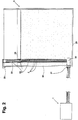
- FIG. 1 wherein the arrangement of the device according to the present invention is shown.
- a tank stock 3 is connected through a bundle of inlet lines 2, described in detail below in the text and in the Fig. 2 , to a main collector 7.
- Said bundle of inlet lines 2 supply the main collector 7 with portions of liquid collected a various heights in the tank 3.
- Each inlet lines is connected to the main collector 7 through an its own dedicated inlet 24.
- the liquid is collected each meter of height. Since the oil stock tanks normally have variable diameters but height of about 20 meters, with an inner effective height of about 18 meters, the liquid is collected at one meter from the bottom of the tank 3, and again, meter by meter, up to reach the eighteenth meter of height from the bottom.
- the sampling points of liquid in the tank are eighteen and consequently the inlet lines 2 are eighteen too, like the inlet 24 of the inlet lines 2 in the main collector 7.
- Each inlet line 2 is provided with an its own valve 26 which is automatically controlled for permitting or preventing the introduction of liquid in the main collector 7.
- the liquid flows into the main collector 7 because the liquid head in the tank 3 is normally situated higher than the main collector 7, thus the liquid reaches for gravity the main collector 7.
- the main collector 7 can be conveniently depressurized.
- one or more pumps can pump the liquid from the tank 3 to the main collector 7.
- the main collector 7 is filled with the liquid corresponding to the sampling height selected.
- the main collector 7 is configured to contain a quantity of collected liquid sufficient to fill the containers 12 and to perform all the online measurements required.
- the main collector 7, as shown in Fig. 1 can be a rectilinear conduit, arranged in vertical with respect to the ground, fluidly connected to a plurality of inlet lines 2.
- Said inlet points 24 can be arranged at various heights of the rectilinear conduit and on both sides of the same, as represented in Fig. 1 .
- Said main collector 7 can comprise a semicircular shaped pipe 8 which connects opposite sides of the main collector 7.
- the semicircular shaped pipe 8 connects the lower end with the upper end of the rectilinear conduit.
- the ring so realized thus the group constituted by the main collector 7 and the semicircular shaped pipe 8, is fluidly connected to a first portion of the main piping 19, which in turn connects said ring to the pump 4.
- Said ring comprises two valves 23A, 23B arranged along the semicircular shaped pipe 8, respectively upstream and downstream with respect to the main collector 7, as shown in Fig. 1 .
- the liquid in the main collector 7 can be circulated in one sense and in the opposite sense of flowing along said ring.
- the main collector 7 can be emptied from the bottom and the lower half of said ring can be washed with the liquid of the main collector 7.
- the pump 4, closing the valve 23A and opening the valve 23B the main collector 7 can be emptied from the top and the upper half of said ring can be washed with the liquid of the main collector 7.
- This washing procedure of said ring allows to eliminate the traces of the sample previously collected from the ring. For example, if the first phase of a portion of liquid is collected from the tank 3 through the inlet line 2 corresponding to the height of 3 meters, which is rich of impurities due to the fact that is close to the bottom of the tank, the subsequent portion of collected liquid is used to eliminate/reduce the traces of the previous portion of collected liquid and to clean the ring. If the new portion of liquid is collected through the inlet line 2 corresponding to the height of 12 meters, this new portion is circulated in said ring until it can be considered washed. Normally it's enough a single washing cycle of the ring, circulating the new collected liquid in one sense of flowing and in the opposite sense. Sometime it can be required two or more washing cycles.
- the portion of liquid used for washing is then re-sent in the tank 3 by means of the pump 4 and a return-pipe 18.
- the main collector 7 can be depressed opening one of the two valves 23A or 23B, acting the pump 4 and closing the valve 26 arranged on the inlet lines 2.
- the second portion of the main piping, indicated by the number 20, is arranged downstream the pump 4.
- a degaser 10 to collect the liquid and decant it in order to remove the gas within it.
- Said gas can accumulate in the liquid due to the turbulences generated by the pump 4.
- the liquid Internally to the degaser 10 the liquid is maintained with an almost constant level for guaranteeing a great discharge of gas from the liquid.
- the liquid is collected by the bottom of the degaser 10 for obtaining a flat liquid.
- the in-line measuring instrument 5 Along the portion 20 of the main piping or on a parallel pipe 9 of said portion is arranged the in-line measuring instrument 5.
- the parallel pipe 9 branches from the portion 20 of the main piping downstream the pump 4 and/or the degaser 10, and rejoins the same downstream a valve 28 arranged on the portion 20. In this way the in-line measuring instrument 5 can be bypassed if necessary, for example in case of maintenance.
- the incline measuring instrument 5 can be fluidly connected to the main piping 20 in a direct manner or, alternatively, through the parallel pipe 9.
- the in-line measuring instrument 5 can be configured to measure one or more of the following parameters of the liquid: density, viscosity, temperature, electrical conductivity, or sulphur content.
- This instrument allows to perform a characterization of the portion of the liquid collected. This characterization allows to operate choices on the subsequent treatments, for example the refinement on the liquid of the tank 3.
- a prompt analysis of the density allows to qualify the liquid, while, a comparison of the on time density at more than one levels allows to evaluate the homogeneity degree of the liquid contained in the tank.
- measurements on the temperature, viscosity, electrical conductivity and sulphur content can be used to qualify the liquid in the tank.
- the measurement performed by the instrument 5 is an in-line measurement, thus a direct measurement on the liquid that is flowing in the pipeline and it's performed in continuous.
- a return-pipe 18 branches and connects the main piping 20 to the tank 3, permitting to send back the sampled liquid to the tank 3.
- the most downstream portion 20 of the main piping can be connected to a dosimeter 11.
- the dosimeter 11 allows to collect a predetermined quantity of liquid from the main piping 20, for example 1 liter.
- This predetermined quantity of liquid can be then delivered to the packing section 6 through a further portion of the main piping, indicated with the reference 21. Said portion 21 couples the dosimeter 11 to the packing section 6.
- the packing section 6 allows to purge the collected liquid into one or more removable container 12.
- the packing section 6 comprises a dispensing head 13 configured to selectively purge the liquid received by the main collector 7, in particular by the dosimeter 11.
- the dispensing head 13 is installed on a carriage 25 movably connected to a rail 29.
- the movement system of said carriage 25 is preferably of pneumatic type, for avoiding electric devices in a zone at elevated risk of explosion and for satisfying the ATEX regulations: the rule 2014/34/UE, which is directed to the manufacturer of equipments intended for use in potentially explosive atmospheres, and the rule 99/92/CE, for the safe and safety of workers in explosive atmospheres.
- the carriage 25 is configured to move between predetermined positions corresponding to dispensing points. Positioning the removable containers 12 in predetermined positions defined by a rack 30, the mouth of the containers 12 is in correspondence of said predetermined positions of the carriage 25. Being the container 12 and the dispensing head 13 vertically aligned, the liquid dispensed by means of the dispensing head 13 falls in the removable container 12.
- the vertical alignment of dispensing head 13 and the container 12 is realized maintaining rest the dispensing head 13, while the rack 30 moves horizontally, moving the container 12 with respect to the dispensing head 13.
- the dosimeter 11 is a pneumatic cylinder configured for sucking a predetermined quantity of liquid and successively pumping the same quantity
- the liquid can be delivered to the head 13 by the dosimeter 11 itself.
- the action of the pump 4 allows the dispensing of liquid from the dispensing head 13.
- the removable containers 12 can be three bottles made of metal 12B, 12C, 12C, 12D with a capacity of 1 liter each one, like those typically used for sampling of oil products, and a bigger container 12A.
- the bigger container 12A has a capacity which is able to contain as much samples as the number of inlet lines from the tank 3.
- the collecting levels are eighteen and so the collectable samples through the inlet lines 2 are eighteen.
- the bigger container 12A can have a capacity of 18 liters if the dosimeter has a capacity of 1 liter.
- the collection of all levels of tank 3 allows to obtain a complete sampling of the liquid of tank 3. Furthermore, the sampling of all levels allows to perform analysis in continuous on the collected liquid, being the container removable and transportable to a laboratory.
- the containers 12, filled of the collected liquid of the tank 3, can be closed by means of a closure apparatus (not shown).
- Said closure apparatus places a cap over the container 12 for avoiding the contamination or the evaporation of the collected liquid.
- Said apparatus can comprise a rotary cylinder pneumatically acted, preliminary equipped with preformed or adhesive caps. The cylinder rotates and places the caps on the mouth of the container 12.
- removable containers 12 can be closed with a rubber cork.
- the dispensing head 13 can be purged with a jet of compressed gas, preferably nitrogen.
- the collected liquid can be dispensed through the dispensing head 13 in one of the removable containers 12.
- the sloop container 15 is fluidly connected to the pump 4 by means of a pipe 17 and part of the main piping 19. From the pump 4, the sloop container 15 is also fluidly connected to the tank 3 by means of a portion of the main piping 20 and the return-pipe 18.
- the sloop container 15 can be emptied in the tank 3.
- the device 1 can further comprise a gas distribution system 16 of compressed gas.
- Said distribution system 16 comprises a source of gas, for example a cylinder or a gas distribution grid.
- Said gas can be air, nitrogen or other inert gas.
- the under pressure gas of said distribution system 16 can be used for one or more of the following activities: purge the dispensing head 13, make inert the sloop container 15, empty and clean the main collector 7.
- the distribution system 16 can be fluidly connected to one or more of the following elements: packing section 6, sloop container 15, collecting point 31, main collector 7.
- the device 1 according to the present invention can be contained in a container 27 configured to be transportable. Said container 27 is opened on more sides for allowing the recirculation of air and avoiding to accumulate explosive gasses. For further applications, different from oil and petrochemical, the container 27 can be closed, provided that is ventilated.
- Said container 27 further protects the elements arranged inside it.
- Said container 27 is configured to contain the device 1 and only a portion of the inlet lines 2 which are mainly arranged outside the container 27 to connect the tank 3, which is arranged far from the device 1.
- the electric controls of the sampling device 1 are contained in a framework compliant with ATEX rules for avoiding deflagration risks.
- the device 1 can comprise a local control unit 14 suitable for controlling the valves, the measurement instruments 5, the packing section 6, electro-mechanical or pneumatic actuators of the device 1, and all other elements.
- Said local control unit 14 can be an autonomous programmable device.
- Said control unit can comprise one or more hardware and/or software components configured to call, decode, execute, archive, analyze, share, evaluate and/or categorize information.
- said control unit 14 can comprise a processor, an archiving means, a memory, an in/out module, a communication interface and a human-machine interface (not shown).
- the processor is configured to execute the instructions contained in the memory.
- Said memory can comprise a program executable by said processor.
- Said processor and said memory are furthermore configured to send/receive data through said in/out module and/or said communication interface.
- the communication interface can be of the type wireless.
- the interface man-machine allows the interaction between the operator and the local control unit 14 for displaying the collected data and for entering the control instructions for the device 1.
- a further scope of the present invention is represented by a liquid sampling system comprising a direct tank liquid sampling device 1 according to the first scope of the present invention, a liquid tank stock 3, a surge pipe 30 arranged vertically in the liquid tank stock 3 and containing at least a portion of inlet lines 2 of the sampling device 1.
- FIG. 2 With reference to Fig. 2 is schematically shown a section of the tank 3 and in particular its inner portion, wherein a surge pipe 30 is vertically arranged.
- Said surge pipe 30 is configured to contain an initial portion of each inlet line 2 of the sampling device 1.
- the inlet lines 2 are arranged in parallel, in the surge pipe 30, to form a bundle of pipes.
- Each inlet line 2 comprises an inlet end 33 through which the liquid of the tank 3 can enter and can be transported to the sampling device 1. That ends of the inlet lines 2 are arranged into the surge pipe 30.
- Said surge pipe 30 can be a pipe having a holed wall, through which the liquid of the tank 3 can flow.
- Said surge pipe 30 has a height which is substantially equal to that of the tank 3. The liquid in the surge pipe 3 is quite and can be collected with the inlet lines 2.
- Said bundle of pipes 30 maintains its vertical position by means of a lower support 32 arranged close to the bottom 29 of the tank 3, by means of a pass through hole on the floating roof 28 of the tank 3 and by means of a upper support 35 anchored to the external wall 34 of the tank 3.
- the surge pipe 30 is installed at a distance that is more than 500 mm, preferably more than 750 mm, from the inner surface of the tank, to avoid that impurities of the wall are sucked.
- a feedthrough element 31 allows the exit of the bundle of pipes of inlet lines 2 from the inner to the outer of the tank 3. Said feedthrough element 31 is configured so that the tight of the tank 3 is guaranteed.
- the pipe bundle came out of the tank 3 can be connected to the sampling device 1 above described.
- each inlet line 2 of the pipe bundle is connected to the main collector 7 by means of dedicated inlets 24.
- the system so conceived allows a direct sampling of the liquid of the tank stock 3.
- a further scope of the present invention is represented by a sampling method for direct sampling a liquid, for example a hydrocarbon or a petrochemical product, comprising the steps of:
- a first washing phase of the main collector 7 is performed. Said washing can be performed circulating a first portion of the new sample of collected liquid. The method uses the new sample, thus the subsequent in timing, for washing the main collector 7 of traces of the previous sample collected.
- a similar operation can be performed in the packing section 6.
- a second washing phase with a second portion of the new sample of collected liquid, can be performed circulating the new sample on the packing section 6.
- a last scope of the present invention is a monitoring plant (not shown) of a group of tanks comprising a plurality of liquid sampling systems according to the second scope of the present invention and a central control unit.
- Said group of tanks can comprise a plurality of tank stocks 3, each one fluidly connected with the respective sampling device 1.
- Said monitoring plant can comprise a central control unit connected to local control units 14 of the direct tank liquid sampling devices 1.
- Said central control unit allows to remotely and centrally control the devices 1.
- said central control unit can be installed in a control room of the plant wherein the tanks 3 are installed.
- Said plant can be for example a refinery plant or a petrochemical plant.
- Each tank 3 is thus equipped with its own sampling system which allows to automatically act the valves, the pumps, the electromechanical actuators, and all other elements of said sampling devices 1.
- Said monitoring plant allows to remotely operate the devices 1 for programming the collections at different heights in the various tanks 3 of the tanks park. Said plant further allows to remotely monitor the physical parameters of the liquid contained in the tanks 3, so to determine and fix the subsequent manufacturing processes for the liquid.
Landscapes
- Life Sciences & Earth Sciences (AREA)
- Hydrology & Water Resources (AREA)
- Physics & Mathematics (AREA)
- Health & Medical Sciences (AREA)
- Chemical & Material Sciences (AREA)
- Analytical Chemistry (AREA)
- Biochemistry (AREA)
- General Health & Medical Sciences (AREA)
- General Physics & Mathematics (AREA)
- Immunology (AREA)
- Pathology (AREA)
- Sampling And Sample Adjustment (AREA)
Abstract
Description
- The present invention relates to a system for sampling and analysing a portion of liquid, preferably a hydrocarbon or a chemical substance, collected from a tank, preferably a big tank stock like those for stocking the mineral oils or the intermediate products of an oil refinery or petrochemical plant.
- In particular, the present invention relates to a system for collecting a predetermined quantity of liquid, for enabling analyses on a sample of the liquid itself, and for performing these activities safely and without the manual intervention of an operator.
- The present invention further relates to a method for operating, sampling and cleaning the system itself.
- Traditionally a sample in a tank is collected manually by means of a sampling bottle, thus a metallic vessel provided with a cord that is lowered directly in the inner of the tank for performing the collection.
- This manual process has been in the time gone automatized and simplified by means of systems collecting the liquid directly from the tank.
- These systems suffer of the inconvenient that tend to get blocked and dirty in the conjunction area of the piping with the tank wall, and further do not guarantee the required representativity of the collected samples.
- Direct sampling systems from a tank which are easy to be maintained, reliable over time and able to guarantee the representativity of the collected sample are not available in the state of the art.
- A further problem is the possibility to operate such activities without a direct contact with the product to be collected, and without the presence of an operator in the tank area, which is normally dangerous for the human health and safety.
- The above mentioned disadvantages of the background art are now solved by a direct tank liquid sampling device according to a first scope of the present invention. Said device comprising a plurality of inlet lines to supply a liquid of a liquid tank stock to a main collector; a pump configured to circulate a collected liquid in the device; a packing section for packing a portion of the collected liquid; a main piping, fluidly coupling the main collector and the packing section, for supplying the packing section with a portion of said collected liquid; an in-line measuring instrument fluidly coupled to the main piping, in an intermediate position between the main collector and the packing section, for measuring one or more of the following liquid parameters: density, viscosity, temperature, electrical conductivity, or sulphur content.
- Advantageously said sampling device allows to sample in continuous a liquid contained in a tank stock without the operator intervention.
- In this way, the risk for the operator of falling in the tank or to breathe dangerous volatile substances, like benzene or Sulphur dioxide is avoided.
- The sampled products are generally oil or petrochemical products like: crude oil, oil, gasoline, diesel, kerosene, jet fuel, fuel oil, naphtha, virgin naphtha, and in general all products coming from the oil refining, included the petrochemical products. The present invention is also applicable to alimentary liquids, like olive oil or wine.
- Advantageously said device allows the analysis in continuous of predetermined parameters indicative of the liquid quality of the collected liquid.
- A second scope of the present invention is a liquid sampling system comprising a direct tank liquid sampling device according to the first scope of the present invention, a liquid tank stock, and a surge pipe arranged vertically in the liquid tank stock and containing at least a portion of the inlet lines of the sampling device.
- Said system, thanks to the surge pipe, allows to collect the liquid of the tank at a suitable distance from the internal wall of the tank and at several heights of the same. The representativity of the collected sample is guaranteed, because the sample is not collected close to the internal wall of the tank.
- Furthermore, thanks to this characteristic, the block of inlet lines with dirty contained over the surface of the internal walls of the tank is avoided. Finally, the surge pipe protects the bundle of inlet pipes from great turbulences that can be generated during the mix and treatment activities of the product.
- A third scope of the present invention is a method for direct sampling a liquid comprising the steps of:
- supplying a main collector with the liquid of a liquid stock tank by means of a plurality of inlet lines;
- pumping the collected liquid towards a packing section;
- selectively measuring one or more of the following parameters of the collected liquid before the liquid enters the packing section: density, viscosity, temperature, electrical conductivity, or sulphur content;
- packing the collected liquid into at least one removable container in the packing section.
- A fourth scope of the present invention is a monitoring plant of a group of tanks comprising a plurality of liquid sampling systems according to the second scope of the present invention and a centralized control unit. Said centralized control unit being configured to dialog and recover information from the local control units of direct tank liquid sampling devices.
- According to the present description, the term tank or stock tank means a cylindrical vessel, raising vertical above ground, having a height comprised between 10 and 24 meters and a diameter comprised between 5 and 40 meters.
- These and other advantages will appear in more detail from the detailed description, in the following, of non-limiting embodiments with reference to annexed drawings.
- In the drawings:
-
Fig. 1 shows a schematic view of a device according to the present invention; -
Fig. 2 shows a schematic view of a system according to the present invention and a section of a stock tank wherein a surge pipe is installed. - The following description of one or more preferred embodiments refers to the attached drawings.
- The same reference numbers in different drawings identify the same or similar elements.
- The scope of the invention is defined in the annexed claims.
- The various technical details, structures and characteristics of the following embodiments can be combined or interchanged in any appropriate manner.
- To comprehend the inventive concept of the present solution reference can be done to
Fig. 1 , wherein the arrangement of the device according to the present invention is shown. - in particular, a
tank stock 3 is connected through a bundle ofinlet lines 2, described in detail below in the text and in theFig. 2 , to a main collector 7. Said bundle ofinlet lines 2 supply the main collector 7 with portions of liquid collected a various heights in thetank 3. - Each inlet lines is connected to the main collector 7 through an its own
dedicated inlet 24. To eachinlet 24 and eachinlet line 2 corresponds a predetermined height of sampling in thetank 3. - Normally, the liquid is collected each meter of height. Since the oil stock tanks normally have variable diameters but height of about 20 meters, with an inner effective height of about 18 meters, the liquid is collected at one meter from the bottom of the
tank 3, and again, meter by meter, up to reach the eighteenth meter of height from the bottom. - In this example, the sampling points of liquid in the tank are eighteen and consequently the
inlet lines 2 are eighteen too, like theinlet 24 of theinlet lines 2 in the main collector 7. - Depending on the liquid head in the
tank 3, some sampling points can be immersed in the liquid and other no. - Each
inlet line 2 is provided with an itsown valve 26 which is automatically controlled for permitting or preventing the introduction of liquid in the main collector 7. - if one of the
valves 26 is opened, a height from which the liquid is collected from thetank 3 is selected. - Then the liquid flows in the
inlet line 2 dedicated to the specific selected height and enters in the main collector 7. - The liquid flows into the main collector 7 because the liquid head in the
tank 3 is normally situated higher than the main collector 7, thus the liquid reaches for gravity the main collector 7. For facilitating this outflow, the main collector 7 can be conveniently depressurized. When the distance between thedevice 1 and thetank 3 is excessive, one or more pumps can pump the liquid from thetank 3 to the main collector 7. - When the
valve 26 is open, the main collector 7 is filled with the liquid corresponding to the sampling height selected. - The main collector 7 is configured to contain a quantity of collected liquid sufficient to fill the containers 12 and to perform all the online measurements required.
- The main collector 7, as shown in
Fig. 1 , can be a rectilinear conduit, arranged in vertical with respect to the ground, fluidly connected to a plurality ofinlet lines 2. Saidinlet points 24 can be arranged at various heights of the rectilinear conduit and on both sides of the same, as represented inFig. 1 . - Said main collector 7 can comprise a semicircular shaped
pipe 8 which connects opposite sides of the main collector 7. In particular, when the main collector 7 is a rectilinear conduit, the semicircularshaped pipe 8 connects the lower end with the upper end of the rectilinear conduit. - The ring so realized, thus the group constituted by the main collector 7 and the semicircular
shaped pipe 8, is fluidly connected to a first portion of themain piping 19, which in turn connects said ring to the pump 4. - Said ring comprises two
valves pipe 8, respectively upstream and downstream with respect to the main collector 7, as shown inFig. 1 . - Acting the pump 4 and opening/closing in a proper way the
valves valve 23A and closing thevalve 23B, the main collector 7 can be emptied from the bottom and the lower half of said ring can be washed with the liquid of the main collector 7. On the contrary, acting the pump 4, closing thevalve 23A and opening thevalve 23B, the main collector 7 can be emptied from the top and the upper half of said ring can be washed with the liquid of the main collector 7. - This washing procedure of said ring allows to eliminate the traces of the sample previously collected from the ring. For example, if the first phase of a portion of liquid is collected from the
tank 3 through theinlet line 2 corresponding to the height of 3 meters, which is rich of impurities due to the fact that is close to the bottom of the tank, the subsequent portion of collected liquid is used to eliminate/reduce the traces of the previous portion of collected liquid and to clean the ring. If the new portion of liquid is collected through theinlet line 2 corresponding to the height of 12 meters, this new portion is circulated in said ring until it can be considered washed. Normally it's enough a single washing cycle of the ring, circulating the new collected liquid in one sense of flowing and in the opposite sense. Sometime it can be required two or more washing cycles. - The portion of liquid used for washing is then re-sent in the
tank 3 by means of the pump 4 and a return-pipe 18. - As already indicated, the main collector 7 can be depressed opening one of the two
valves valve 26 arranged on the inlet lines 2. - Normally the samples from the
tank 3 are collected one by one and between one and the other a washing cycle of the main collector 7 is performed. - The second portion of the main piping, indicated by the
number 20, is arranged downstream the pump 4. Along saidportion 20 can be arranged adegaser 10 to collect the liquid and decant it in order to remove the gas within it. Said gas can accumulate in the liquid due to the turbulences generated by the pump 4. Internally to thedegaser 10 the liquid is maintained with an almost constant level for guaranteeing a great discharge of gas from the liquid. The liquid is collected by the bottom of thedegaser 10 for obtaining a flat liquid. - Along the
portion 20 of the main piping or on aparallel pipe 9 of said portion is arranged the in-line measuring instrument 5. Theparallel pipe 9 branches from theportion 20 of the main piping downstream the pump 4 and/or thedegaser 10, and rejoins the same downstream avalve 28 arranged on theportion 20. In this way the in-line measuring instrument 5 can be bypassed if necessary, for example in case of maintenance. - The incline measuring instrument 5 can be fluidly connected to the
main piping 20 in a direct manner or, alternatively, through theparallel pipe 9. - The in-line measuring instrument 5 can be configured to measure one or more of the following parameters of the liquid: density, viscosity, temperature, electrical conductivity, or sulphur content.
- This instrument allows to perform a characterization of the portion of the liquid collected. This characterization allows to operate choices on the subsequent treatments, for example the refinement on the liquid of the
tank 3. - In particular, a prompt analysis of the density allows to qualify the liquid, while, a comparison of the on time density at more than one levels allows to evaluate the homogeneity degree of the liquid contained in the tank. Depending on the liquid contained in the tank, measurements on the temperature, viscosity, electrical conductivity and sulphur content can be used to qualify the liquid in the tank.
- The measurement performed by the instrument 5 is an in-line measurement, thus a direct measurement on the liquid that is flowing in the pipeline and it's performed in continuous.
- For the reason, in-line instruments of density, viscosity, temperature, electrical conductivity or sulphur content can be employed and for this reason no further details of them are here provided.
- Downstream the incline measuring instrument 5 a return-
pipe 18 branches and connects themain piping 20 to thetank 3, permitting to send back the sampled liquid to thetank 3. - The most
downstream portion 20 of the main piping can be connected to adosimeter 11. Thedosimeter 11 allows to collect a predetermined quantity of liquid from themain piping 20, for example 1 liter. - This predetermined quantity of liquid can be then delivered to the packing section 6 through a further portion of the main piping, indicated with the
reference 21. Saidportion 21 couples thedosimeter 11 to the packing section 6. - The packing section 6 allows to purge the collected liquid into one or more removable container 12.
- In particular, the packing section 6 comprises a dispensing
head 13 configured to selectively purge the liquid received by the main collector 7, in particular by thedosimeter 11. - The dispensing
head 13 is installed on acarriage 25 movably connected to arail 29. The movement system of saidcarriage 25 is preferably of pneumatic type, for avoiding electric devices in a zone at elevated risk of explosion and for satisfying the ATEX regulations: the rule 2014/34/UE, which is directed to the manufacturer of equipments intended for use in potentially explosive atmospheres, and the rule 99/92/CE, for the safe and safety of workers in explosive atmospheres. - The
carriage 25 is configured to move between predetermined positions corresponding to dispensing points. Positioning the removable containers 12 in predetermined positions defined by arack 30, the mouth of the containers 12 is in correspondence of said predetermined positions of thecarriage 25. Being the container 12 and the dispensinghead 13 vertically aligned, the liquid dispensed by means of the dispensinghead 13 falls in the removable container 12. - In an alternative version of the invention, the vertical alignment of dispensing
head 13 and the container 12 is realized maintaining rest the dispensinghead 13, while therack 30 moves horizontally, moving the container 12 with respect to the dispensinghead 13. - When the
dosimeter 11 is a pneumatic cylinder configured for sucking a predetermined quantity of liquid and successively pumping the same quantity, the liquid can be delivered to thehead 13 by thedosimeter 11 itself. Alternatively, the action of the pump 4 allows the dispensing of liquid from the dispensinghead 13. - The removable containers 12 can be three bottles made of
metal bigger container 12A. Thebigger container 12A has a capacity which is able to contain as much samples as the number of inlet lines from thetank 3. For example, in the above mentioned case, the collecting levels are eighteen and so the collectable samples through theinlet lines 2 are eighteen. In this case, thebigger container 12A can have a capacity of 18 liters if the dosimeter has a capacity of 1 liter. The collection of all levels oftank 3 allows to obtain a complete sampling of the liquid oftank 3. Furthermore, the sampling of all levels allows to perform analysis in continuous on the collected liquid, being the container removable and transportable to a laboratory. - The containers 12, filled of the collected liquid of the
tank 3, can be closed by means of a closure apparatus (not shown). Said closure apparatus places a cap over the container 12 for avoiding the contamination or the evaporation of the collected liquid. Said apparatus can comprise a rotary cylinder pneumatically acted, preliminary equipped with preformed or adhesive caps. The cylinder rotates and places the caps on the mouth of the container 12. - Alternatively said removable containers 12 can be closed with a rubber cork.
- Before a subsequent dispensing the main piping and the conduits of the packing section 6 are washed with the following washing process.
- the
carriage 25 is positioned in a further position that vertically corresponds to acollecting point 31 fluidly connected to a sloop container; - a portion of the new collected liquid is dispensed through the dispensing
head 13 for washing the pipes of traces of previously dispensed liquid; - the dispensed portion is collected in the
sloop container 15 which periodically is emptied sending back the collected liquid to thetank 3. - After the steps of the washing process, the dispensing
head 13 can be purged with a jet of compressed gas, preferably nitrogen. - When the dispensing
head 13 is cleaned by the traces of previously dispensed liquid, the collected liquid can be dispensed through the dispensinghead 13 in one of the removable containers 12. - The
sloop container 15 is fluidly connected to the pump 4 by means of apipe 17 and part of themain piping 19. From the pump 4, thesloop container 15 is also fluidly connected to thetank 3 by means of a portion of themain piping 20 and the return-pipe 18. - Acting the pump 4 and opening/closing specific valves arranged along the cited pipes, the
sloop container 15 can be emptied in thetank 3. - The
device 1 can further comprise agas distribution system 16 of compressed gas. -
Said distribution system 16 comprises a source of gas, for example a cylinder or a gas distribution grid. Said gas can be air, nitrogen or other inert gas. The under pressure gas of saiddistribution system 16 can be used for one or more of the following activities: purge the dispensinghead 13, make inert thesloop container 15, empty and clean the main collector 7. - The
distribution system 16 can be fluidly connected to one or more of the following elements: packing section 6,sloop container 15, collectingpoint 31, main collector 7. - The
device 1 according to the present invention can be contained in acontainer 27 configured to be transportable. Saidcontainer 27 is opened on more sides for allowing the recirculation of air and avoiding to accumulate explosive gasses. For further applications, different from oil and petrochemical, thecontainer 27 can be closed, provided that is ventilated. - Said
container 27 further protects the elements arranged inside it. Saidcontainer 27 is configured to contain thedevice 1 and only a portion of theinlet lines 2 which are mainly arranged outside thecontainer 27 to connect thetank 3, which is arranged far from thedevice 1. - The electric controls of the
sampling device 1 are contained in a framework compliant with ATEX rules for avoiding deflagration risks. - Finally the
device 1 according to the present invention can comprise alocal control unit 14 suitable for controlling the valves, the measurement instruments 5, the packing section 6, electro-mechanical or pneumatic actuators of thedevice 1, and all other elements. - Said
local control unit 14 can be an autonomous programmable device. Said control unit can comprise one or more hardware and/or software components configured to call, decode, execute, archive, analyze, share, evaluate and/or categorize information. In particular, saidcontrol unit 14 can comprise a processor, an archiving means, a memory, an in/out module, a communication interface and a human-machine interface (not shown). - The processor is configured to execute the instructions contained in the memory. Said memory can comprise a program executable by said processor. Said processor and said memory are furthermore configured to send/receive data through said in/out module and/or said communication interface. The communication interface can be of the type wireless. The interface man-machine allows the interaction between the operator and the
local control unit 14 for displaying the collected data and for entering the control instructions for thedevice 1. - A further scope of the present invention is represented by a liquid sampling system comprising a direct tank
liquid sampling device 1 according to the first scope of the present invention, aliquid tank stock 3, asurge pipe 30 arranged vertically in theliquid tank stock 3 and containing at least a portion ofinlet lines 2 of thesampling device 1. - With reference to
Fig. 2 is schematically shown a section of thetank 3 and in particular its inner portion, wherein asurge pipe 30 is vertically arranged. - Said
surge pipe 30 is configured to contain an initial portion of eachinlet line 2 of thesampling device 1. The inlet lines 2 are arranged in parallel, in thesurge pipe 30, to form a bundle of pipes. Eachinlet line 2 comprises aninlet end 33 through which the liquid of thetank 3 can enter and can be transported to thesampling device 1. That ends of theinlet lines 2 are arranged into thesurge pipe 30. - Said
surge pipe 30 can be a pipe having a holed wall, through which the liquid of thetank 3 can flow. Saidsurge pipe 30 has a height which is substantially equal to that of thetank 3. The liquid in thesurge pipe 3 is quite and can be collected with the inlet lines 2. - Said bundle of
pipes 30 maintains its vertical position by means of alower support 32 arranged close to the bottom 29 of thetank 3, by means of a pass through hole on the floatingroof 28 of thetank 3 and by means of aupper support 35 anchored to theexternal wall 34 of thetank 3. - The
surge pipe 30 is installed at a distance that is more than 500 mm, preferably more than 750 mm, from the inner surface of the tank, to avoid that impurities of the wall are sucked. - A
feedthrough element 31 allows the exit of the bundle of pipes ofinlet lines 2 from the inner to the outer of thetank 3. Saidfeedthrough element 31 is configured so that the tight of thetank 3 is guaranteed. - The pipe bundle came out of the
tank 3 can be connected to thesampling device 1 above described. In particular, eachinlet line 2 of the pipe bundle is connected to the main collector 7 by means ofdedicated inlets 24. - The system so conceived allows a direct sampling of the liquid of the
tank stock 3. - A further scope of the present invention is represented by a sampling method for direct sampling a liquid, for example a hydrocarbon or a petrochemical product, comprising the steps of:
- supplying a main collector 7 with the liquid coming from a
liquid stock tank 3 by means of a plurality ofinlet lines 2; - pumping the collected liquid towards a packing section 6;
- selectively measuring one or more of the following parameters of the collected liquid before the liquid enters the packing section 6: density, viscosity, temperature, electrical conductivity, or sulphur content;
- packing the collected liquid into at least one
removable container - In particular, to avoid contamination of the new collected sample with the previously collected sample, before a subsequent packing phase, a first washing phase of the main collector 7 is performed. Said washing can be performed circulating a first portion of the new sample of collected liquid. The method uses the new sample, thus the subsequent in timing, for washing the main collector 7 of traces of the previous sample collected.
- A similar operation can be performed in the packing section 6. A second washing phase, with a second portion of the new sample of collected liquid, can be performed circulating the new sample on the packing section 6.
- A last scope of the present invention is a monitoring plant (not shown) of a group of tanks comprising a plurality of liquid sampling systems according to the second scope of the present invention and a central control unit.
- Said group of tanks can comprise a plurality of
tank stocks 3, each one fluidly connected with therespective sampling device 1. - Said monitoring plant can comprise a central control unit connected to
local control units 14 of the direct tankliquid sampling devices 1. Said central control unit allows to remotely and centrally control thedevices 1. In a particular embodiment, said central control unit can be installed in a control room of the plant wherein thetanks 3 are installed. Said plant can be for example a refinery plant or a petrochemical plant. - Each
tank 3 is thus equipped with its own sampling system which allows to automatically act the valves, the pumps, the electromechanical actuators, and all other elements of saidsampling devices 1. - Said monitoring plant allows to remotely operate the
devices 1 for programming the collections at different heights in thevarious tanks 3 of the tanks park. Said plant further allows to remotely monitor the physical parameters of the liquid contained in thetanks 3, so to determine and fix the subsequent manufacturing processes for the liquid. - To conclude, it is clear that the invention so conceived can be susceptible of various modifications and variations, all covered by the scope of the invention; furthermore all the details are replaceable by technically equivalent elements. In practice, the materials used and the dimensions may be any according to the technical requirements.
- Finally, here-below are described some advantageous embodiments:
- Method for direct sampling a liquid comprising the steps of:
- supplying a main collector 7 with the liquid of a
liquid stock tank 3 by means of a plurality ofinlet lines 2; - pumping the collected liquid towards a packing section 6;
- selectively measuring one or more of the following parameters of the collected liquid before the liquid enters the packing section 6: density, viscosity, temperature, electrical conductivity, or sulphur content;
- packing the collected liquid into at least one
removable container
- supplying a main collector 7 with the liquid of a
- Method for direct sampling a liquid according to the previous embodiment, wherein before a subsequent phase of packing a first cleaning phase of the main collector 7 with a first portion of a subsequent collected liquid sample occurs.
- Method for direct sampling a liquid according to one of the two previous embodiments, further comprising a second cleaning phase of the packing section 6 with a second portion of the subsequent collected liquid sample.
- Device, system or method according to present invention, wherein said liquid is hydrocarbon or a chemical product.
- Monitoring plant of a group of tanks comprising a plurality of liquid sampling systems according to the present invention and a central control unit connected to
local control units 14 of the direct tankliquid sampling devices 1.
Claims (15)
- Direct tank liquid sampling device (1) comprising:- a plurality of inlet lines (2) to supply a liquid of a liquid tank stock (3) to a main collector (7);- a pump (4) configured to circulate the collected liquid in the device (1);- a packing section (6);- a main piping (19, 20, 21) fluidly coupling the main collector (7) and the packing section (6) for supplying the packing section (6) with a portion of said collected liquid;- an in-line measuring instrument (5) fluidly coupled to the main piping ((19, 20, 21) in an intermediate position between the main collector (7) and the packing section (6), said incline measuring instrument (5) being configured for measuring one or more of the following liquid parameters; density, viscosity, temperature, electrical conductivity, or sulphur content.
- Direct tank liquid sampling device (1) according to claim 1, wherein said incline measuring instrument (5) is arranged along said main piping (19, 20, 21) or along a parallel piping (9) fluidly coupled to the main piping (19, 20, 21).
- Direct tank liquid sampling device (1) according to claim 1 or 2, wherein the inlet lines (2) collect the liquid of the liquid tank stock (3) at predetermined heights which are different each other.
- Direct tank liquid sampling device (1) according to any one of preceding claims, wherein the main collector (7) is fluidly coupled to the pump (4) through a semicircular shaped pipe (8) connecting the bottom to the top of the main collector (7) so that a portion of the collected liquid can be circulated in the main collector (7) by means of the pump (4) and acting two valves (23A, 23B) arranged along the semicircular shaped pipe (8), respectively upstream and downstream the main collector (7).
- Direct tank liquid sampling device (1) according to any one of preceding claims, further comprising a degasser (10) arranged along the main piping (19, 20, 21) downstream the pump (4).
- Direct tank liquid sampling device (1) according to any one of preceding claims, further comprising a dosimeter (11) arranged along the main piping (19, 20, 21) upstream the packing section (6).
- Direct tank liquid sampling device (1) according to any of preceding claims, wherein the packing section (6) comprises:- art least one removable container (12A, 12B, 12C, 12D) to be filled;- a dispensing head (13) configured to selectively pour the liquid received from the main collector (7);- a carriage (25) configured to move the dispensing head (13) with respect to the at least one removable container (12A, 12B, 12C, 12D) so to align the dispensing head (13) with a mouth of said at least one removable container (12A, 12B, 12C, 12D) during the pouring.
- Direct tank liquid sampling device (1) according to claim 7, wherein the packing section (6) further comprises a slop container (15) wherein the dispensing head (13) pours a portion of liquid between subsequent dispensing phases so to eliminate eventual traces of a previous pouring.
- Direct tank liquid sampling device (1) according to claim 8, wherein the slop container (15) is fluidly connected to the inlet of the pump (4) through a by-pass piping (17).
- Direct tank liquid sampling device (1) according to any one of preceding claims, further comprising a return-pipe (18) fluidly connected to the main piping (19, 20, 21) and configured to flow-back the collected liquid from the device (1) to the liquid stock tank (3).
- Direct tank liquid sampling device (1) according to any one of preceding claims, further comprising a distribution system of nitrogen or air compressed (16) configured to purge the dispensing head (13) and/or to the main collector (7) and/or to the slop container (15).
- Direct tank liquid sampling device (1) according to any one of preceding claims, wherein the sampling device (1) is configured to be transportable.
- Liquid sampling system comprising:- a direct tank liquid sampling device (1) according to one or more of preceding claims;- a liquid tank stock (3);- a surge pipe (30) arranged vertically in the liquid tank stock (3) and containing at least a portion of the inlet lines (2) of the sampling device (1).
- Liquid sampling system according to claim 13, wherein the surge pipe comprises a perforated pipe (30) wherein the inlet lines (2) are arranged so that their ends are positioned at different heights of the tank (3) and are fluidly in contact with the liquid contained in the tank (3).
- Liquid sampling system according to claim 13 or 14, wherein the surge pipe (30) is positioned at least 500 mm from the internal wall of the liquid tank stock (3).
Priority Applications (3)
| Application Number | Priority Date | Filing Date | Title |
|---|---|---|---|
| EP17000716.5A EP3396351B1 (en) | 2017-04-26 | 2017-04-26 | Device and system for directly sampling a liquid of a tank |
| PCT/EP2018/000217 WO2018197040A1 (en) | 2017-04-26 | 2018-04-24 | Device, system and method for direct sampling a liquid of a tank |
| US16/605,059 US11226269B2 (en) | 2017-04-26 | 2018-04-24 | Device, system and method for direct sampling a liquid of a tank |
Applications Claiming Priority (1)
| Application Number | Priority Date | Filing Date | Title |
|---|---|---|---|
| EP17000716.5A EP3396351B1 (en) | 2017-04-26 | 2017-04-26 | Device and system for directly sampling a liquid of a tank |
Publications (2)
| Publication Number | Publication Date |
|---|---|
| EP3396351A1 true EP3396351A1 (en) | 2018-10-31 |
| EP3396351B1 EP3396351B1 (en) | 2022-11-09 |
Family
ID=59399200
Family Applications (1)
| Application Number | Title | Priority Date | Filing Date |
|---|---|---|---|
| EP17000716.5A Active EP3396351B1 (en) | 2017-04-26 | 2017-04-26 | Device and system for directly sampling a liquid of a tank |
Country Status (3)
| Country | Link |
|---|---|
| US (1) | US11226269B2 (en) |
| EP (1) | EP3396351B1 (en) |
| WO (1) | WO2018197040A1 (en) |
Families Citing this family (1)
| Publication number | Priority date | Publication date | Assignee | Title |
|---|---|---|---|---|
| US11371914B2 (en) | 2019-09-11 | 2022-06-28 | Saudi Arabian Oil Company | Automated hydrogen sulfide sampler |
Citations (7)
| Publication number | Priority date | Publication date | Assignee | Title |
|---|---|---|---|---|
| NL45547C (en) * | ||||
| FR726701A (en) * | 1931-11-24 | 1932-06-02 | Dampfkessel Und Gasometerfabri | Device for taking liquid from a closed receptacle for testing |
| US4413533A (en) * | 1981-10-29 | 1983-11-08 | Exxon Research And Engineering Co. | Sampling device for isokinetic sampling |
| US20050087027A1 (en) * | 2003-10-28 | 2005-04-28 | General Electric Company | A configurable multi-point sampling method and system for representative gas composition measurements in a stratified gas flow stream |
| WO2007113668A2 (en) * | 2006-04-04 | 2007-10-11 | Obschestvo S Ogranichennoy Otvetstvennostyu | Device for the removal of liquid samples from the storage tank |
| WO2012061872A1 (en) * | 2010-11-08 | 2012-05-18 | Mezurx Pty Ltd | Sample analyser |
| US20150000385A1 (en) * | 2013-06-28 | 2015-01-01 | General Electric Company | Pressure management system for sensors |
Family Cites Families (3)
| Publication number | Priority date | Publication date | Assignee | Title |
|---|---|---|---|---|
| FR2379816A1 (en) * | 1977-02-02 | 1978-09-01 | Tepral Grpt Interet Economique | PROCEDURE AND INSTALLATION FOR THE AUTOMATIC COLLECTION OF BEER SAMPLES TO BE ANALYZED |
| FR2475223A1 (en) * | 1980-02-05 | 1981-08-07 | Kronenbourg Brasseries | INDEPENDENT ISOBAROMETRIC SAMPLING APPARATUS FOR SAMPLING SAMPLES ON GASEOUS DRINKS |
| US9285354B2 (en) * | 2007-04-02 | 2016-03-15 | The United States Of America As Represented By The Administrator Of The U.S. Environmental Protection Agency | Systems and methods for the detection of low-level harmful substances in a large volume of fluid |
-
2017
- 2017-04-26 EP EP17000716.5A patent/EP3396351B1/en active Active
-
2018
- 2018-04-24 WO PCT/EP2018/000217 patent/WO2018197040A1/en active Application Filing
- 2018-04-24 US US16/605,059 patent/US11226269B2/en active Active
Patent Citations (7)
| Publication number | Priority date | Publication date | Assignee | Title |
|---|---|---|---|---|
| NL45547C (en) * | ||||
| FR726701A (en) * | 1931-11-24 | 1932-06-02 | Dampfkessel Und Gasometerfabri | Device for taking liquid from a closed receptacle for testing |
| US4413533A (en) * | 1981-10-29 | 1983-11-08 | Exxon Research And Engineering Co. | Sampling device for isokinetic sampling |
| US20050087027A1 (en) * | 2003-10-28 | 2005-04-28 | General Electric Company | A configurable multi-point sampling method and system for representative gas composition measurements in a stratified gas flow stream |
| WO2007113668A2 (en) * | 2006-04-04 | 2007-10-11 | Obschestvo S Ogranichennoy Otvetstvennostyu | Device for the removal of liquid samples from the storage tank |
| WO2012061872A1 (en) * | 2010-11-08 | 2012-05-18 | Mezurx Pty Ltd | Sample analyser |
| US20150000385A1 (en) * | 2013-06-28 | 2015-01-01 | General Electric Company | Pressure management system for sensors |
Also Published As
| Publication number | Publication date |
|---|---|
| US20210131919A1 (en) | 2021-05-06 |
| EP3396351B1 (en) | 2022-11-09 |
| US11226269B2 (en) | 2022-01-18 |
| WO2018197040A1 (en) | 2018-11-01 |
Similar Documents
| Publication | Publication Date | Title |
|---|---|---|
| FI88211B (en) | ANORDNING FOER EMISSIONSFRI PROVTAGNING AV LAETT AVDUNSTANDE VAETSKOR | |
| US11226269B2 (en) | Device, system and method for direct sampling a liquid of a tank | |
| US4332768A (en) | Arrangement for supplying metered quantities of reagent liquid to the test tubes of an analyzing apparatus | |
| CN206358659U (en) | A kind of chemical reagent storage device | |
| RU2686352C1 (en) | Measuring system | |
| US9737918B2 (en) | Method and apparatus for cleaning railroad tank cars | |
| EP2803623A1 (en) | Filling unit of a container filling machine, having improved storing capability | |
| US9835525B2 (en) | Multiphase sample container and method | |
| US5115686A (en) | Vapor free multi-liquid sampler | |
| CN107091759A (en) | A kind of reaction vessel vacuumizing method sampler | |
| CN106353140A (en) | Vacuum sampling system | |
| CN206861256U (en) | A kind of chemistry laboratory central liquid supply system | |
| EP2455946B1 (en) | Method for filling a bottle with a radioactive fluid-base mixture | |
| CN206318260U (en) | A kind of holding vessel | |
| CN105910853A (en) | Instantaneous sampling apparatus for radioactive bench test | |
| CN116413079A (en) | Method for automatically sampling liquid storage tank | |
| CN207941530U (en) | A kind of reaction kettle for m-phthaloyl chloride production | |
| US20210255067A1 (en) | System and method for liquid displacement auto-sampling | |
| RU2749256C1 (en) | Mobile standard of the 2nd discharge for verification of well measurement units | |
| CN109516435A (en) | A kind of carbon fiber production liquid chemical material sampling remnant liquid recovering device and method | |
| RU2754759C1 (en) | Process fluid sampling device | |
| CN208291520U (en) | Bottle placer discharge automatic control system and bulking system | |
| US1416354A (en) | Vacuum sampler for tanks of refined oil and gasoline | |
| RU2750371C1 (en) | Separation tank for well measurement units | |
| US10161836B2 (en) | Pipeline sampling system and method |
Legal Events
| Date | Code | Title | Description |
|---|---|---|---|
| PUAI | Public reference made under article 153(3) epc to a published international application that has entered the european phase |
Free format text: ORIGINAL CODE: 0009012 |
|
| STAA | Information on the status of an ep patent application or granted ep patent |
Free format text: STATUS: THE APPLICATION HAS BEEN PUBLISHED |
|
| AK | Designated contracting states |
Kind code of ref document: A1 Designated state(s): AL AT BE BG CH CY CZ DE DK EE ES FI FR GB GR HR HU IE IS IT LI LT LU LV MC MK MT NL NO PL PT RO RS SE SI SK SM TR |
|
| AX | Request for extension of the european patent |
Extension state: BA ME |
|
| STAA | Information on the status of an ep patent application or granted ep patent |
Free format text: STATUS: REQUEST FOR EXAMINATION WAS MADE |
|
| 17P | Request for examination filed |
Effective date: 20190415 |
|
| RBV | Designated contracting states (corrected) |
Designated state(s): AL AT BE BG CH CY CZ DE DK EE ES FI FR GB GR HR HU IE IS IT LI LT LU LV MC MK MT NL NO PL PT RO RS SE SI SK SM TR |
|
| RAP1 | Party data changed (applicant data changed or rights of an application transferred) |
Owner name: MATULLI, RICCARDO Owner name: TRAVAGLI, FURIO |
|
| RIN1 | Information on inventor provided before grant (corrected) |
Inventor name: TRAVAGLI, FURIO Inventor name: MATULLI, RICCARDO |
|
| STAA | Information on the status of an ep patent application or granted ep patent |
Free format text: STATUS: EXAMINATION IS IN PROGRESS |
|
| 17Q | First examination report despatched |
Effective date: 20211202 |
|
| GRAP | Despatch of communication of intention to grant a patent |
Free format text: ORIGINAL CODE: EPIDOSNIGR1 |
|
| STAA | Information on the status of an ep patent application or granted ep patent |
Free format text: STATUS: GRANT OF PATENT IS INTENDED |
|
| RIC1 | Information provided on ipc code assigned before grant |
Ipc: G01N 1/20 20060101ALN20220530BHEP Ipc: G01N 1/16 20060101ALI20220530BHEP Ipc: G01N 1/14 20060101AFI20220530BHEP |
|
| RIC1 | Information provided on ipc code assigned before grant |
Ipc: G01N 1/20 20060101ALN20220620BHEP Ipc: G01N 1/16 20060101ALI20220620BHEP Ipc: G01N 1/14 20060101AFI20220620BHEP |
|
| INTG | Intention to grant announced |
Effective date: 20220704 |
|
| GRAS | Grant fee paid |
Free format text: ORIGINAL CODE: EPIDOSNIGR3 |
|
| GRAA | (expected) grant |
Free format text: ORIGINAL CODE: 0009210 |
|
| STAA | Information on the status of an ep patent application or granted ep patent |
Free format text: STATUS: THE PATENT HAS BEEN GRANTED |
|
| AK | Designated contracting states |
Kind code of ref document: B1 Designated state(s): AL AT BE BG CH CY CZ DE DK EE ES FI FR GB GR HR HU IE IS IT LI LT LU LV MC MK MT NL NO PL PT RO RS SE SI SK SM TR |
|
| REG | Reference to a national code |
Ref country code: GB Ref legal event code: FG4D |
|
| REG | Reference to a national code |
Ref country code: CH Ref legal event code: EP Ref country code: AT Ref legal event code: REF Ref document number: 1530677 Country of ref document: AT Kind code of ref document: T Effective date: 20221115 |
|
| REG | Reference to a national code |
Ref country code: DE Ref legal event code: R096 Ref document number: 602017063450 Country of ref document: DE |
|
| REG | Reference to a national code |
Ref country code: IE Ref legal event code: FG4D |
|
| REG | Reference to a national code |
Ref country code: LT Ref legal event code: MG9D |
|
| REG | Reference to a national code |
Ref country code: NL Ref legal event code: MP Effective date: 20221109 |
|
| REG | Reference to a national code |
Ref country code: AT Ref legal event code: MK05 Ref document number: 1530677 Country of ref document: AT Kind code of ref document: T Effective date: 20221109 |
|
| PG25 | Lapsed in a contracting state [announced via postgrant information from national office to epo] |
Ref country code: SE Free format text: LAPSE BECAUSE OF FAILURE TO SUBMIT A TRANSLATION OF THE DESCRIPTION OR TO PAY THE FEE WITHIN THE PRESCRIBED TIME-LIMIT Effective date: 20221109 Ref country code: PT Free format text: LAPSE BECAUSE OF FAILURE TO SUBMIT A TRANSLATION OF THE DESCRIPTION OR TO PAY THE FEE WITHIN THE PRESCRIBED TIME-LIMIT Effective date: 20230309 Ref country code: NO Free format text: LAPSE BECAUSE OF FAILURE TO SUBMIT A TRANSLATION OF THE DESCRIPTION OR TO PAY THE FEE WITHIN THE PRESCRIBED TIME-LIMIT Effective date: 20230209 Ref country code: LT Free format text: LAPSE BECAUSE OF FAILURE TO SUBMIT A TRANSLATION OF THE DESCRIPTION OR TO PAY THE FEE WITHIN THE PRESCRIBED TIME-LIMIT Effective date: 20221109 Ref country code: FI Free format text: LAPSE BECAUSE OF FAILURE TO SUBMIT A TRANSLATION OF THE DESCRIPTION OR TO PAY THE FEE WITHIN THE PRESCRIBED TIME-LIMIT Effective date: 20221109 Ref country code: ES Free format text: LAPSE BECAUSE OF FAILURE TO SUBMIT A TRANSLATION OF THE DESCRIPTION OR TO PAY THE FEE WITHIN THE PRESCRIBED TIME-LIMIT Effective date: 20221109 Ref country code: AT Free format text: LAPSE BECAUSE OF FAILURE TO SUBMIT A TRANSLATION OF THE DESCRIPTION OR TO PAY THE FEE WITHIN THE PRESCRIBED TIME-LIMIT Effective date: 20221109 |
|
| PG25 | Lapsed in a contracting state [announced via postgrant information from national office to epo] |
Ref country code: RS Free format text: LAPSE BECAUSE OF FAILURE TO SUBMIT A TRANSLATION OF THE DESCRIPTION OR TO PAY THE FEE WITHIN THE PRESCRIBED TIME-LIMIT Effective date: 20221109 Ref country code: PL Free format text: LAPSE BECAUSE OF FAILURE TO SUBMIT A TRANSLATION OF THE DESCRIPTION OR TO PAY THE FEE WITHIN THE PRESCRIBED TIME-LIMIT Effective date: 20221109 Ref country code: LV Free format text: LAPSE BECAUSE OF FAILURE TO SUBMIT A TRANSLATION OF THE DESCRIPTION OR TO PAY THE FEE WITHIN THE PRESCRIBED TIME-LIMIT Effective date: 20221109 Ref country code: IS Free format text: LAPSE BECAUSE OF FAILURE TO SUBMIT A TRANSLATION OF THE DESCRIPTION OR TO PAY THE FEE WITHIN THE PRESCRIBED TIME-LIMIT Effective date: 20230309 Ref country code: HR Free format text: LAPSE BECAUSE OF FAILURE TO SUBMIT A TRANSLATION OF THE DESCRIPTION OR TO PAY THE FEE WITHIN THE PRESCRIBED TIME-LIMIT Effective date: 20221109 Ref country code: GR Free format text: LAPSE BECAUSE OF FAILURE TO SUBMIT A TRANSLATION OF THE DESCRIPTION OR TO PAY THE FEE WITHIN THE PRESCRIBED TIME-LIMIT Effective date: 20230210 |
|
| PG25 | Lapsed in a contracting state [announced via postgrant information from national office to epo] |
Ref country code: NL Free format text: LAPSE BECAUSE OF FAILURE TO SUBMIT A TRANSLATION OF THE DESCRIPTION OR TO PAY THE FEE WITHIN THE PRESCRIBED TIME-LIMIT Effective date: 20221109 |
|
| PG25 | Lapsed in a contracting state [announced via postgrant information from national office to epo] |
Ref country code: SM Free format text: LAPSE BECAUSE OF FAILURE TO SUBMIT A TRANSLATION OF THE DESCRIPTION OR TO PAY THE FEE WITHIN THE PRESCRIBED TIME-LIMIT Effective date: 20221109 Ref country code: RO Free format text: LAPSE BECAUSE OF FAILURE TO SUBMIT A TRANSLATION OF THE DESCRIPTION OR TO PAY THE FEE WITHIN THE PRESCRIBED TIME-LIMIT Effective date: 20221109 Ref country code: EE Free format text: LAPSE BECAUSE OF FAILURE TO SUBMIT A TRANSLATION OF THE DESCRIPTION OR TO PAY THE FEE WITHIN THE PRESCRIBED TIME-LIMIT Effective date: 20221109 Ref country code: DK Free format text: LAPSE BECAUSE OF FAILURE TO SUBMIT A TRANSLATION OF THE DESCRIPTION OR TO PAY THE FEE WITHIN THE PRESCRIBED TIME-LIMIT Effective date: 20221109 Ref country code: CZ Free format text: LAPSE BECAUSE OF FAILURE TO SUBMIT A TRANSLATION OF THE DESCRIPTION OR TO PAY THE FEE WITHIN THE PRESCRIBED TIME-LIMIT Effective date: 20221109 |
|
| REG | Reference to a national code |
Ref country code: DE Ref legal event code: R097 Ref document number: 602017063450 Country of ref document: DE |
|
| PG25 | Lapsed in a contracting state [announced via postgrant information from national office to epo] |
Ref country code: SK Free format text: LAPSE BECAUSE OF FAILURE TO SUBMIT A TRANSLATION OF THE DESCRIPTION OR TO PAY THE FEE WITHIN THE PRESCRIBED TIME-LIMIT Effective date: 20221109 Ref country code: AL Free format text: LAPSE BECAUSE OF FAILURE TO SUBMIT A TRANSLATION OF THE DESCRIPTION OR TO PAY THE FEE WITHIN THE PRESCRIBED TIME-LIMIT Effective date: 20221109 |
|
| PLBE | No opposition filed within time limit |
Free format text: ORIGINAL CODE: 0009261 |
|
| STAA | Information on the status of an ep patent application or granted ep patent |
Free format text: STATUS: NO OPPOSITION FILED WITHIN TIME LIMIT |
|
| 26N | No opposition filed |
Effective date: 20230810 |
|
| PGFP | Annual fee paid to national office [announced via postgrant information from national office to epo] |
Ref country code: GB Payment date: 20230613 Year of fee payment: 7 |
|
| PG25 | Lapsed in a contracting state [announced via postgrant information from national office to epo] |
Ref country code: SI Free format text: LAPSE BECAUSE OF FAILURE TO SUBMIT A TRANSLATION OF THE DESCRIPTION OR TO PAY THE FEE WITHIN THE PRESCRIBED TIME-LIMIT Effective date: 20221109 |
|
| REG | Reference to a national code |
Ref country code: CH Ref legal event code: PL |
|
| PG25 | Lapsed in a contracting state [announced via postgrant information from national office to epo] |
Ref country code: LU Free format text: LAPSE BECAUSE OF NON-PAYMENT OF DUE FEES Effective date: 20230426 |
|
| REG | Reference to a national code |
Ref country code: BE Ref legal event code: MM Effective date: 20230430 |
|
| PG25 | Lapsed in a contracting state [announced via postgrant information from national office to epo] |
Ref country code: MC Free format text: LAPSE BECAUSE OF FAILURE TO SUBMIT A TRANSLATION OF THE DESCRIPTION OR TO PAY THE FEE WITHIN THE PRESCRIBED TIME-LIMIT Effective date: 20221109 |
|
| PG25 | Lapsed in a contracting state [announced via postgrant information from national office to epo] |
Ref country code: MC Free format text: LAPSE BECAUSE OF FAILURE TO SUBMIT A TRANSLATION OF THE DESCRIPTION OR TO PAY THE FEE WITHIN THE PRESCRIBED TIME-LIMIT Effective date: 20221109 Ref country code: LI Free format text: LAPSE BECAUSE OF NON-PAYMENT OF DUE FEES Effective date: 20230430 Ref country code: CH Free format text: LAPSE BECAUSE OF NON-PAYMENT OF DUE FEES Effective date: 20230430 |
|
| REG | Reference to a national code |
Ref country code: IE Ref legal event code: MM4A |
|
| PG25 | Lapsed in a contracting state [announced via postgrant information from national office to epo] |
Ref country code: BE Free format text: LAPSE BECAUSE OF NON-PAYMENT OF DUE FEES Effective date: 20230430 |
|
| PG25 | Lapsed in a contracting state [announced via postgrant information from national office to epo] |
Ref country code: IE Free format text: LAPSE BECAUSE OF NON-PAYMENT OF DUE FEES Effective date: 20230426 |
|
| PG25 | Lapsed in a contracting state [announced via postgrant information from national office to epo] |
Ref country code: IE Free format text: LAPSE BECAUSE OF NON-PAYMENT OF DUE FEES Effective date: 20230426 |
|
| PGFP | Annual fee paid to national office [announced via postgrant information from national office to epo] |
Ref country code: DE Payment date: 20240424 Year of fee payment: 8 |
|
| PGFP | Annual fee paid to national office [announced via postgrant information from national office to epo] |
Ref country code: IT Payment date: 20240424 Year of fee payment: 8 Ref country code: FR Payment date: 20240408 Year of fee payment: 8 |