EP3396324A2 - Systèmes d'affichage avionique et procédés de génération d'affichages avioniques comprenant une symbologie de lutte contre l'incendie aérienne - Google Patents
Systèmes d'affichage avionique et procédés de génération d'affichages avioniques comprenant une symbologie de lutte contre l'incendie aérienne Download PDFInfo
- Publication number
- EP3396324A2 EP3396324A2 EP18164816.3A EP18164816A EP3396324A2 EP 3396324 A2 EP3396324 A2 EP 3396324A2 EP 18164816 A EP18164816 A EP 18164816A EP 3396324 A2 EP3396324 A2 EP 3396324A2
- Authority
- EP
- European Patent Office
- Prior art keywords
- fire
- avionic display
- avionic
- controller
- thermal image
- Prior art date
- Legal status (The legal status is an assumption and is not a legal conclusion. Google has not performed a legal analysis and makes no representation as to the accuracy of the status listed.)
- Pending
Links
- 238000000034 method Methods 0.000 title claims abstract description 12
- 230000000007 visual effect Effects 0.000 claims description 21
- 238000001931 thermography Methods 0.000 claims description 4
- 230000015654 memory Effects 0.000 description 14
- 238000009826 distribution Methods 0.000 description 8
- XLYOFNOQVPJJNP-UHFFFAOYSA-N water Substances O XLYOFNOQVPJJNP-UHFFFAOYSA-N 0.000 description 8
- 239000013618 particulate matter Substances 0.000 description 6
- 230000003190 augmentative effect Effects 0.000 description 4
- 239000003550 marker Substances 0.000 description 3
- 239000000779 smoke Substances 0.000 description 3
- 230000003068 static effect Effects 0.000 description 3
- 230000004075 alteration Effects 0.000 description 2
- 230000001419 dependent effect Effects 0.000 description 2
- 238000010586 diagram Methods 0.000 description 2
- 239000000446 fuel Substances 0.000 description 2
- 230000006870 function Effects 0.000 description 2
- 238000005259 measurement Methods 0.000 description 2
- 230000008569 process Effects 0.000 description 2
- 230000004044 response Effects 0.000 description 2
- 230000007704 transition Effects 0.000 description 2
- RZVHIXYEVGDQDX-UHFFFAOYSA-N 9,10-anthraquinone Chemical compound C1=CC=C2C(=O)C3=CC=CC=C3C(=O)C2=C1 RZVHIXYEVGDQDX-UHFFFAOYSA-N 0.000 description 1
- 230000009471 action Effects 0.000 description 1
- 230000002411 adverse Effects 0.000 description 1
- 230000007175 bidirectional communication Effects 0.000 description 1
- 230000008859 change Effects 0.000 description 1
- 239000002131 composite material Substances 0.000 description 1
- 230000001010 compromised effect Effects 0.000 description 1
- 230000002708 enhancing effect Effects 0.000 description 1
- 230000037406 food intake Effects 0.000 description 1
- 231100001261 hazardous Toxicity 0.000 description 1
- 230000036541 health Effects 0.000 description 1
- 238000007726 management method Methods 0.000 description 1
- 238000013507 mapping Methods 0.000 description 1
- 230000003340 mental effect Effects 0.000 description 1
- 238000004377 microelectronic Methods 0.000 description 1
- 238000012544 monitoring process Methods 0.000 description 1
- 238000000926 separation method Methods 0.000 description 1
Images


Classifications
-
- G—PHYSICS
- G06—COMPUTING; CALCULATING OR COUNTING
- G06T—IMAGE DATA PROCESSING OR GENERATION, IN GENERAL
- G06T11/00—2D [Two Dimensional] image generation
- G06T11/60—Editing figures and text; Combining figures or text
-
- B—PERFORMING OPERATIONS; TRANSPORTING
- B64—AIRCRAFT; AVIATION; COSMONAUTICS
- B64D—EQUIPMENT FOR FITTING IN OR TO AIRCRAFT; FLIGHT SUITS; PARACHUTES; ARRANGEMENT OR MOUNTING OF POWER PLANTS OR PROPULSION TRANSMISSIONS IN AIRCRAFT
- B64D43/00—Arrangements or adaptations of instruments
-
- A—HUMAN NECESSITIES
- A62—LIFE-SAVING; FIRE-FIGHTING
- A62C—FIRE-FIGHTING
- A62C3/00—Fire prevention, containment or extinguishing specially adapted for particular objects or places
- A62C3/02—Fire prevention, containment or extinguishing specially adapted for particular objects or places for area conflagrations, e.g. forest fires, subterranean fires
- A62C3/0228—Fire prevention, containment or extinguishing specially adapted for particular objects or places for area conflagrations, e.g. forest fires, subterranean fires with delivery of fire extinguishing material by air or aircraft
-
- G—PHYSICS
- G01—MEASURING; TESTING
- G01C—MEASURING DISTANCES, LEVELS OR BEARINGS; SURVEYING; NAVIGATION; GYROSCOPIC INSTRUMENTS; PHOTOGRAMMETRY OR VIDEOGRAMMETRY
- G01C23/00—Combined instruments indicating more than one navigational value, e.g. for aircraft; Combined measuring devices for measuring two or more variables of movement, e.g. distance, speed or acceleration
- G01C23/005—Flight directors
Definitions
- the following disclosure relates generally to aircraft and, more particularly, to avionic display systems and methods for generating avionic displays including aerial firefighting symbology, which enhances situational awareness and aids pilot decision-making during aerial firefighting operations.
- Aerial firefighting commonly involves the operation of aircraft (A/C) in low altitude, high risk flight environments.
- Such flight environments may encompass fire-affected areas ranging from sparsely-populated or unpopulated regions of wilderness to densely-populated urban areas, such city environments in which A/C may be employed to combat structure fires in high-rise buildings.
- the flight environments may be characterized by elevated and shifting thermal gradients, dynamic wind conditions, and fire-induced updrafts. Visibility may be compromised by adverse weather conditions, time of day, and/or by the presence of large amounts of smoke, ash, and other airborne particulate matter.
- the airspace encompassing a fire-affected region may be occupied by other A/C, elevated terrain, man-made structures, and other obstacles.
- an EVS is an aircraft-based system including at least one thermal image sensor, such as an infrared camera or millimeter wave radar sensor, which collects thermal image data external to the A/C during flight.
- the thermal image data collected by the EVS sensor is presented to the aircrew as an EVS image, which appears on a Head Up Display (HUD) or a Head Down Display (HDD) located in the A/C cockpit.
- the EVS image may be combined or blended with another database-dependent display to yield a composite display.
- a Combined Vision System (CVS) display can be produced by integrating an EVS image into the Synthetic Vision System (SVS) image of a Synthetic Vision Primary Flight Display (SV-PFD).
- the larger database-dependent SVS image provides a contextual view exceeding the scope of the EVS image utilizing a stored terrain database, while the EVS image provides real-time, sensor-derived visual information more closely resembling the actual flight environment of the A/C.
- Such a CVS display and, specifically, the EVS image may thus serve as a useful, vision-enhancing tool during aerial firefighting operations in which visibility is often hindered.
- CVS displays and other avionic display incorporating EVS images are generally not adapted to address the unique challenges and mental tasks encountered by pilots in the context of aerial firefighting.
- avionic display systems such as vision enhancing systems having augmented functionalities, which further improve situational awareness and aid pilot decision-making during aerial firefighting operations.
- Embodiments of such avionic display systems are described herein, as are methods for generating avionic displays including aerial firefighting symbology.
- the avionic display system includes an avionic display device, a thermal image sensor, and a controller operably coupled to the display device and to the thermal image sensor.
- the thermal image sensor can be an infrared camera, a millimeter wave radar device, or another sensor suitable for gathering thermal image data within a sensor Field of View (FOV) external to an aircraft (A/C).
- FOV Field of View
- the controller compiles a fire map of a fire-affected area in proximity of the A/C based, at least in part, on the thermal image data collected by the thermal image sensor.
- the controller Concurrently, the controller generates a first avionic display having a display Field of View (FOV) on the avionic display device.
- the first avionic display is generated to include symbology representative of the sensor FOV, as well as graphics representative portions of the fire map located outside of the sensor FOV.
- the first avionic display can produced as a two dimensional avionic display, such as a Horizontal Navigation (HNAV) or Vertical Navigation (VNAV) display.
- the first avionic display can produced as a three dimensional avionic display, such as a Combined Vision System (CVS) display.
- HNAV Horizontal Navigation
- VNAV Vertical Navigation
- CVS Combined Vision System
- the avionic display system includes an avionic display device and a controller, which is operably coupled to the display device and which generates an avionic display thereon.
- the controller generates avionic display to include graphics depicting a fire-affected area in proximity of the A/C, as well as symbology indicative of a current A/C position and the boundaries of a virtual fire alert envelope surrounding the current A/C position.
- the controller may further selectively generate visual alerts on the avionic display when, for example, fire encroaches into the fire alert envelope.
- the controller may also actively adjust the boundaries of the fire alert envelope with respect to the A/C position in response to variations in the current A/C position (current altitude, latitude, and/or longitude), current wind speeds, local fire temperatures, and/or other such parameters.
- the controller may also be configured to establish whether a fire escape route is available to the A/C based, at least in part, on the fire map and the fire alert envelope. Specifically, the controller may repeatedly search for and identify horizontal or substantially level fire escape routes that avoid encroachment of fire into the fire alert envelope and which require minimal, if any gain in altitude by the A/C.
- the controller If establishing that a substantially level fire escape route is available to the A/C, the controller generates graphics on the avionic display identifying the fire escape route. Conversely, if the controller cannot establish a substantially level fire escape route, a visual alert may be generated on the avionic display.
- Methods are further provided for generating avionic displays including aerial firefighting symbology.
- Embodiments of the method are carried-out by an avionic display system including an avionic display device, a thermal image sensor (e.g., an infrared camera or MMW radar device) having a sensor FOV, and a controller operably coupled to the avionic display device and to the thermal image sensor.
- the controller may establish a fire map of a fire-affected area in proximity of the A/C by recalling the fire map from a memory, by receiving the fire map over a wireless datalink, and/or by compiling the fire map utilizing thermal image data received from the sensor.
- the controller further updates the fire map on repeated bases utilizing, for example, thermal image data captured by the thermal image sensor as the sensor FOV sweeps across the fire-affected area.
- the controller utilizes the fire map to generate a first avionic display on the avionic display device.
- the controller generates the first avionic display to include symbology denoting the sensor FOV and graphics representative of portions of the fire map located outside of the sensor FOV, but within the display FOV.
- the aerial firefighting symbology can include graphics representative of a fire map, which plots or charts active combustive regions or fire zones over a geographical area.
- the fire map may also contain other fire-related information, such as local fire temperature distribution charts, airborne-particulate matter density charts, the locations of any firebreaks or water resources in proximity of the A/C, and vector information pertaining to the rate and direction of fire propagation.
- the fire map may be initially provided to the ownship A/C from an external source (e.g., transmitted to the A/C en route to the fire-affected area) and/or initially compiled by the avionic display system utilizing at least one thermal image sensor carried by the A/C.
- the thermal image sensor can be, for example, an infrared camera or Millimeter Wave (MMV) radar included within an Enhanced Vision System (EVS).
- MMV Millimeter Wave
- EVS Enhanced Vision System
- the avionic display system repeatedly updates the fire map in accordance with newly-received thermal image data provided by the thermal sensor; e.g., the appropriate regions of the fire map may be updated utilizing the thermal image data as the sensor Field of View (FOV) sweeps across different portions of the fire-affected area.
- FOV Field of View
- the fire map may also be updated in accordance with data received from sources external to the ownship A/C, such as thermal imaging data supplied by other manned A/C, satellite, or unmanned A/C in proximity of the fire-affected area. Any newly-received fire map data may be compared to the stored fire map and corresponding adjustments may be made to update the fire map in accordance with the most recent or reliable data available.
- the avionic display is similarly updated to present the most recent version of the fire map to the aircrew of the A/C.
- Embodiments of the avionic display system may visually integrate regions of the fire map onto corresponding portions of a two dimensional (2D) or three dimensional (3D) display environment. Graphics representative of actively-burning regions located within the sensor FOV may be visually distinguished from graphics representative of the fire map located outside the sensor FOV, but within the display FOV.
- the avionic display system may also impart any fire graphics within the sensor FOV to have a varied (e.g. more striking) appearance relative to the fire graphics outside the sensor FOV.
- the fire graphics within the sensor FOV may be generated to have an actively-burning appearance by applying a fire animation or by producing a visual representation of the real-time thermal data captured by the thermal image sensor.
- the boundaries of the EVS image may be visually distinguish by shading the EVS image, by producing a boarder graphic around the EVS image, or in another manner.
- graphics may be generated to indicate the current spread and range of the sensor FOV.
- Additional graphics or symbology supporting aerial firefighting efforts may also be produced on the avionic display or displays generated by the avionic display system.
- Such graphics can visually convey airborne-particulate matter distributions, local fire temperatures, the location of nearby water resources, and the like. Visual indications of the speed and direction of fire movement, measured or forecast, can also be provided.
- the avionic display system may produce symbology identifying one or more substantially level fire escape routes (egress passages) available to the ownship A/C.
- the avionic display system may generate graphics indicative of a region of space surrounding the A/C position and into which fire encroachment should be avoided. This region of space (hereafter, the "fire alert envelope”) can also be utilized for alerting functionalities.
- the avionic display system may generate alerts when fire encroachment into the fire alert envelope occurs and/or when the ownship A/C is unable to advance forward (or progress on current flight path if significant crab) at the present altitude without fire encroachment into the fire alert envelope.
- an alert may be generated when the avionic display system determines that a substantially level fire escape route is not presently available to the ownship A/C.
- Such alerts may be produced as visual alerts expressed on the avionic display as, for example, alterations in the visual appearance (e.g., color coding) of the fire escape route graphics and/or the fire alert envelope graphics.
- FIG. 1 sets-forth a block diagram of an avionic display system 10 , which is illustrated in accordance with an exemplary and non-limiting embodiment of the present disclosure.
- avionic display system 10 includes the following components or subsystems, each of which may be comprised of one device or multiple interconnected devices: (i) a controller 12, (ii) one or more avionic display devices 14, (iii) ownship data sources 16, (iv) a pilot input interface 18, (v) a memory 20 containing any number of onboard databases 22, and (vi) a datalink subsystem 24 including an antenna 26.
- Controller 12 includes at least first, second, third, and fourth inputs, which are operatively coupled to ownship data sources 16, to pilot input interface 18, to memory 20, and to datalink subsystem 24, respectively. Additionally, controller 12 includes at least first, second, and third outputs, which are operatively coupled to avionic display devices 14, to memory 20, and to datalink subsystem 24, respectively. In further embodiments, avionic display system 10 may include a greater or lesser number of components, which may be interconnected in various different manners and utilizing any combination of wireless or wired (e.g., avionic bus) connections. Although avionic display system 10 is schematically illustrated in FIG. 1 as a single unit, the individual elements and components of avionic display system 10 can be implemented in a distributed manner using any number of physically-distinct and operatively-interconnected pieces of hardware or equipment.
- Avionic display devices 14 may include any number of image-generating devices, which each feature a display screen on which one or more graphical displays are produced. Avionic display devices 14 will often be affixed to the static structure of the A/C cockpit, whether as Head Up Display (HUD) devices, Head Down Display (HDD) devices, or a combination thereof. Alternatively, one or more of avionic display devices 14 may assume the form of or include a movable display device (e.g., head-worn display devices) or a portable display device, such as an Electronic Flight Bag (EFB), tablet, or laptop computer, carried into the A/C cockpit by a pilot or other aircrew member.
- HUD Head Up Display
- HDD Head Down Display
- one or more of avionic display devices 14 may assume the form of or include a movable display device (e.g., head-worn display devices) or a portable display device, such as an Electronic Flight Bag (EFB), tablet, or laptop computer, carried into the A/C cockpit by a pilot or other aircrew member
- avionic display device 14 may not be deployed onboard the A/C itself and may instead be remotely located therefrom; e.g., in certain implementations, the A/C may assume the form of an Unmanned Aerial Vehicle (UAV) included within a UAV system, and the operator or pilot may control the UAV from a remote location.
- UAV Unmanned Aerial Vehicle
- controller 12 drives avionic display devices 14 to generate one or more graphical displays thereon. For example, and as schematically indicated on the left side of FIG.
- controller 12 may drive avionic display devices 14 to generate: (i) a 3D avionic display 28 including aerial firefighting symbology 30, and (ii) a 2D avionic display 32 including aerial firefighting symbology 34.
- Avionic displays 28, 32 may be produced on a single display screen in, for example, a side-by-side or picture-in-picture format. Alternatively, avionic displays 28, 32 may be produced on separate display screens.
- Controller 12 may comprise or be associated with any suitable number of individual microprocessors, flight control computers, navigational equipment, memories (including or in addition to memory 20 ), power supplies, storage devices, interface cards, and other standard components known in the relevant field. Controller 12 may include or cooperate with any number of software programs (e.g., avionics display programs) or instructions (e.g., as stored in memory 20 ) designed to carry out the various methods, process tasks, calculations, and control/display functions described more fully herein. Although illustrated as a separate block in FIG. 1 , memory 20 may be partially or wholly integrated into controller 12 in embodiments.
- software programs e.g., avionics display programs
- instructions e.g., as stored in memory 20
- controller 12 and memory 20 are produced as an Application Specific Integrated Circuit (ASIC), a System-in-Package (SiP), or a microelectronic module.
- Memory 20 may store data utilized to support the operation of avionic display system 10 .
- memory 20 may store any number of databases 22, which may include navigational, weather, and/or terrain databases.
- databases 22 may be included in an Enhanced Ground Proximity Warning System (EGPWS) or a Runway Awareness and Advisory System (RAAS).
- EGPWS Enhanced Ground Proximity Warning System
- RAAS Runway Awareness and Advisory System
- controller 12 and the other components of avionic display system 10 may be included or cooperate with any number and type of systems commonly deployed onboard A/C including, for example, a Flight Management System (FMS), an Attitude Heading Reference System (AHRS), an Instrument Landing System (ILS), and an Inertial Reference System (IRS), to list but a few examples.
- FMS Flight Management System
- AHRS Attitude Heading Reference System
- ILS Instrument Landing System
- IRS Inertial Reference System
- Datalink subsystem 24 may assume any form enabling wireless bi-directional communication between the ownship A/C and one or more external data sources, such as a traffic control authority and/or neighboring A/C within the general vicinity of the ownship A/C.
- Datalink subsystem 24 may be utilized to provide Air Traffic Control (ATC) data to the ownship A/C and/or to send information from the ownship A/C to ATC in compliance with known standards and specifications.
- ATC Air Traffic Control
- information may be transmitted to controller 12 via datalink subsystem 24 pertaining to aerial firefighting efforts, such as air traffic information and instructions coordinating aerial and ground-based firefighting teams.
- Data may also be wirelessly received via datalink subsystem 24, which can be utilized by avionic display system 10 to further initially compile, augment, and update the fire map of the fire-affected area.
- data may be wireless transmitted to avionic display system 10 describing additional thermal image data of the fire-affected region collected by other manned A/C, unmanned A/C (e.g., UAVs or drones), satellite, or ground-based resources able to collect such data.
- ownship data sources 16 include multiple onboard sensors and other components suitable for collecting data utilized in carrying-out the processes described herein.
- the particular types of data collected by ownship data sources 16 and provided to controller 12 will vary amongst different embodiments of avionic display system 10 .
- ownship data sources 16 will include a number of flight parameter sensors 38, which supply data to controller 12 describing various different operational conditions of the ownship A/C utilized in generating avionic displays 28, 32.
- Data provided by ownship data sources 16 can include, without limitation: airspeed data; groundspeed data; altitude data; attitude data including pitch data and roll data; yaw data; geographic position data, such as Global Positioning System (GPS) data; data relating to gross A/C weight; time/date information; heading information; data describing current and forecasted atmospheric conditions, such wind speed and direction measurements; flight path data; track data; radar altitude data; geometric altitude data; and data pertaining to fuel consumption, to list but a few examples.
- Ownship data sources 16 may also include at least one thermal image sensor 36, which is capable of detecting fire heat signatures.
- Thermal image sensor 36 can be, for example, a forward-looking infrared camera or a MMW radar located within a radome beneath the A/C or otherwise affixed to the A/C.
- FIG. 2 is a screenshot of an exemplary CVS 40 generated on one of avionic display devices 14 during operation of avionic display system 10 ( FIG. 1 ), as illustrated in accordance with an exemplary embodiment of the present disclosure.
- CVS 40 generally corresponds with 3D avionic display 28 shown in FIG. 1 , although different reference numerals are utilized to emphasize that 3D avionic display 28 need not assume the form of a CVS in all embodiments.
- CVS 40 is generated in a 3D perspective view format as seen from the vantage point of the A/C cockpit.
- CVS 40 can be generated from other vantage points, such as that of a virtual chase plane following the ownship A/C.
- EVS image 42 is a smaller, centralized image combined with or integrated into (e.g., scaled, aligned, and blended with) with SVS image 44, which is larger in scope.
- EVS image 42 is generated utilizing the real-time thermal imaging data captured by thermal image sensor 36 ( FIG. 1 ).
- SVS image 44 is generated utilizing information contained within a terrain database, a navigational database, or a similar database included in databases 22 stored in memory 20 ( FIG. 1 ).
- EVS window When graphics are produced on CVS 40 visually denoting the area of CVS 40 encompassed by EVS image 42, such graphics are generically referred to herein as an "EVS window."
- An example of such an EVS window 45 is shown in FIG. 2 and produced as a dashed box or other border graphic denoting the boundaries of SVS image 44.
- a light shading or similar visual effect may be applied over EFV image 42 shown on CVS 40 to visually distinguish the display area encompassed by image 42 from the broader SVS image 44.
- EVS window is utilized to broadly refer to one or more graphic elements or visual effects, which visually distinguish the display area encompassed by an EVS image (e.g., EVS image 44 ) from a larger display image, such as SVS image 44 of CVS 40.
- EVS image e.g., EVS image 44
- CVS 40 can also include other graphic elements, which visually convey pertinent flight parameters to the pilot or aircrew.
- additional graphic elements are well-known within the avionics industry and can include Horizontal Situation Indicator (HSI) graphics, Attitude Director Indicator (ADI) graphics, airspeed indicator graphics, altitude indicator graphics, Flight Path Vector (FPV) markers, and barometric pressure readouts, to list but a few examples. Many of these graphics are not shown in FIG. 2 to avoid unnecessarily obscuring the drawing. However, a few such graphics are shown in FIG. 2 for context and include an FPV marker 48 and ADI graphics 50, 52, 54.
- HAI Horizontal Situation Indicator
- ADI Attitude Director Indicator
- FPV Flight Path Vector
- ADI graphics 50, 52, 54 are updated, as appropriate, to reflect changes in the attitude of the ownship A/C.
- ADI graphics 50, 52, 54 include an ADI A/C symbol 50 in the form of two L-shaped polygons, a zero pitch reference line 52, and a pitch tape graphic 54.
- CVS 40 is further generated to include aerial firefighting symbology 56, which visually conveys to a pilot (or other viewer of CVS 40 ) information pertaining a fire-affected region in the vicinity of the ownship A/C.
- aerial firefighting symbology 56 includes graphics representative of a number of active-combustive regions or fire zones. Seven fire zones are shown in the current FOV of CVS 40 and SVS scene 44, as represented by fire zone graphics 58(a)-(g). This example notwithstanding, multiple fire zone graphics may not always appear on CVS 40, depending upon a given fire distribution.
- a single fire zone graphic may appear on CVS 40 depicting the unitary conflagration.
- avionic display system 10 revises fire zone graphics 58 on CVS 40 in accordance with changes in the fire distribution, as indicated by the most recent version of the fire map stored within memory 20 ( FIG. 1 ).
- fire zone graphics 58(a)-(g) may appear to merge, separate, and otherwise vary as the real-world fire distribution evolves over time.
- the fire graphics located within the current FOV of thermal image sensor 36 are advantageously generated to have a varied appearance relative to those fire zone graphics located outside of the sensor FOV, but within the current FOV of CVS 40.
- those fire zones (or fire zone portions) included within EVS image 42 and encompassed by EVS window 45 may visually represent the real-time thermal image data recorded by thermal image sensor 36 and, thus, appear to be actively burning or have a flame-like animation applied thereto.
- those fire zones located outside of EVS image 42 may be presented utilizing static graphics (e.g., relatively thick boundary lines), which are mapped onto the 3D SVS terrain of SVS scene 44.
- static graphics e.g., relatively thick boundary lines
- the leftmost portion of graphic 58(b) resides outside of EVS image 42 and is drawn as a thick boundary line in a static or non-animated format.
- the rightmost portion of graphic 58(b) extends into EVS image 42 and is generated to reflect the real-time thermal sensor data, which depicts an actively-burning fire line mapped onto the 3D SVS terrain.
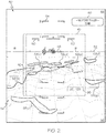
- CVS 40 enables a pilot to quickly distinguish those regions of the displayed fire map located within the current FOV of thermal image sensor 36 (and thus representative of the real-time thermal image data captured by sensor 36 ) from those regions of the displayed fire map located outside of the current sensor FOV (and thus representative of stored fire map data). This is highly useful in the context of aerial firefighting. Additionally, CVS 40 provides the pilot and other aircrew members with a clear, virtual representation of the A/C flight environment, which may vary significantly from the view seen from the A/C cockpit under actual or real-world conditions. This may be appreciated by briefly comparing the screenshot of CVS 40 shown in FIG. 2 to the corresponding real-world view, as seen from the A/C cockpit and shown in FIG. 3 .
- the real-world cockpit view is obscured by poor visibility conditions due to time of day (e.g., nighttime operation), instrumental meteorological conditions, and/or the presence of significant quantities of smoke, ash, or other airborne particulate matter within the airspace surrounding the fire-afflicted region.
- time of day e.g., nighttime operation
- instrumental meteorological conditions e.g., the presence of significant quantities of smoke, ash, or other airborne particulate matter within the airspace surrounding the fire-afflicted region.
- Embodiments of avionic display system 10 may further generate one or more 2D avionic displays, which are augmented to include aerial firefighting symbology.
- the 2D avionic display can be produced as a Vertical Navigation (VNAV) display, such as a Vertical Situation Display (VSD); a Horizontal Navigation (HNAV) display, such as a 2D moving map display; a Multi-Function Display (MFD); or the like.
- FIG. 4 presents a screenshot of an exemplary HNAV display 70, which may be generated by avionic display system 10 concurrently with a 3D avionic display, such as CVS 40 ( FIG. 2 ).
- An ownship A/C icon 72 indicates the current horizontal position (latitude and longitude) of the ownship A/C within geographical area 74 encompassed by HNAV display 70.
- Aerial firefighting symbology 76 is further produced on HNAV display 70 and includes a number of fire zone graphics 78, which represent actively-burning regions within the FOV of HNAV display 70.
- fire zone graphics 78(a)-(h) represent actively-burning regions within the FOV of HNAV display 70.
- Fire zone graphics 78(a)-(h) may distinguished from the other terrain included within geographical area 74 by shading, application of a fill pattern, or a similar visual effect. If desired, the boundaries of fire zone graphics 78(a)-(h) may be demarcated by relatively thick boundary lines or otherwise visually denoted on HNAV display 70.
- HNAV display 70 further includes at least one graphic or icon 80 identifying the FOV of SVS image 44 contained in CVS display 40 ( FIG. 2 ).
- Icon 80 can be produced as a triangular icon including two wedge line graphics 82, which converge toward ownship A/C icon 72.
- the angle between wedge line graphics 82 denotes the spread of the SVS FOV and the spread of the sensor FOV.
- icon 80 can be varied accordingly.
- An arc-shaped dashed line 84 is further provided to visually denote the distance or depth of the sensor FOV.
- Triangular icon 80 extends beyond arc-shaped dashed line 84 to further encompass an extended region 86.
- Extended region 86 thus represents the volume of space further shown in SVS image 44 and encompassed by EVS window 45, but extending beyond the current FOV of thermal image sensor 36.
- Controller 12 of avionic display system 10 may further visually distinguish between those portions of the fire zones located within the sensor FOV from those portions of the fire zones located outside the sensor FOV, but within the display FOV. For example, as indicated in FIG.
- those portions of the fire map residing within the sensor FOV may be color coded to a first color (e.g., red or amber); those portions of the fire map within the SVS FOV, but outside of the sensor FOV may be color coded to a second color (e.g., amber); and those portions of the fire map outside of the SVS FOV may be generated in a third color (e.g. blue, white, or green).
- a first color e.g., red or amber
- those portions of the fire map within the SVS FOV, but outside of the sensor FOV may be color coded to a second color (e.g., amber)
- those portions of the fire map outside of the SVS FOV may be generated in a third color (e.g. blue, white, or green).
- different variations in the visual appearance of the fire graphics may be utilized to visually those regions of the fire map located within the sensor FOV, such as a changes to the opacity or transparency of fire zone graphics 78(a)-(h
- HNAV display 70 is generated to further include a fire alert envelope graphic 88, which surrounds and may be centered about ownship A/C icon 72.
- Fire alert envelope graphic 88 identifies the boundaries of a virtual fire alert envelope, which surrounds the ownship A/C and which is designated as a fire buffer or designated fire-free zone into which fire encroachment should be prevented, to the extent possible.
- the fire alert envelope represented by graphic 88 may be defined by a predetermined radius surrounding the present horizontal position of the A/C. In this case, the radius may be selected based upon A/C type, thermal tolerances of the A/C components, and other factors.
- the fire alert envelope may have more complex symmetrical or asymmetrical 3D shapes. Additionally or alternatively, the boundaries of the fire alert envelope may be actively adjusted in response to changes in any number of dynamic factors, such as local temperatures, wind speeds, and/or fire propagation parameters (e.g., the measured or predicted speed and direction of fire propagation). The boundaries of the fire alert envelope may also be adjusted based upon A/C position (altitude, latitude, and longitude) in certain instances. With respect to altitude, in particular, the current Above Ground Level (AGL) altitude of the ownship A/C may be considered in adjusting the fire alert envelope boundaries to accommodate variations in terrain elevation.
- AGL Above Ground Level
- the shape and/or dimensions fire alert envelope may be adjustable by pilot input, by the A/C owner, by the Original Equipment Manufacturer (OEM), or other such entity.
- OEM Original Equipment Manufacturer
- graphics may be repeatedly or continually adjusted to reflect such alterations to the fire alert envelope boundaries.
- the radius and/or shape of fire alert envelope graphic 88 shown in FIG. 4 may change or morph, as appropriate, to reflect in real-time any adjustments to the fire alert envelope boundaries.
- fire alert envelope graphic 88 is generated as a circular marker, which may be overlaid with a partially transparent pattern or fill color.
- the appearance of fire alert envelope graphic 88 may be modified as appropriate to generate visual alerts useful in the context of aerial firefighting.
- the shading of fire alert envelope graphic 88 may transition from a pre-established informational color (e.g., white or green) to a pre-established caution or warning color (e.g., amber or red) when avionic display system 10 detects the occurrence of a fire-related alert event.
- avionic display system 10 may generate such a visual alert on HNAV display 70 if determining fire has encroached into the fire alert envelope represented by graphic 88. Additionally or alternatively, avionic display system 10 may generate such an alert when determining that the ownship A/C can no longer progress in a forward direction or continue to proceed on the current flight path (if significant crab in the case of a rotary wing A/C) without undesired fire exposure, such as fire encroachment into the fire alert envelope represented by graphic 88.
- Avionic display system 10 may determine whether the above-described alert conditions are satisfied based upon the current A/C position, A/C flight parameters (e.g., flight track, airspeed, altitude, etc.), current wind speed and direction measurements, terrain topology, fire distributions indicated by the stored fire map, fire vector information (e.g., the rate and direction of fire spread), and so on.
- avionic display system 10 may generate a visual alert on HNAV display 70 ( FIG. 4 ) and/or CVS 40 ( FIG. 2 ) in a different manner. For example, and briefly returning to FIG.
- a textual annunciation 90 indicating the alert condition and perhaps advising an responsive action may be produced on CVS.
- Various other audible and/or haptic alerts may also be produced in conjunction with such a visual alert, if so desired.
- multiple fire alert envelopes may be established around the ownship A/C and utilized to generate a series of graded alerts on the avionic display(s) generated by avionic display system 10 , which vary in severity depending upon the urgency of the fire-alert condition.
- Embodiments of avionic display system 10 may further monitor fire escape routes available to the ownship A/C when located within or flown into a fire-affected region.
- avionic display system 10 continually monitors for the availability of at least one substantially level fire escape route; that is, a fire escape route or path available to the A/C, which avoids undesired A/C exposure to fire (or to highly elevated heat levels caused by fire) that does not require the ownship A/C to climb by more than a threshold amount.
- avionic display system 10 may establish such a substantially level fire escape route by repeatedly mapping or plotting a projected horizontal path, which extends from the present position of the ownship A/C to a fire-free zone and which avoids fire encroachment into the above-described fire alert envelope.
- controller 12 of avionic display system 10 may consider various different factors or parameters, such as the present fire distribution indicated by the fire map route, the boundaries of the fire alert envelope, wind direction and speed, nearby flight obstacles, elevated terrain topology, firebreaks (e.g., bodies of water or areas devoid of vegetation), and other such information.
- avionic display system 10 may further consider forecasted weather conditions and fire parameters, such as fire distributions projected into the near future based upon current fire locations, wind speed and direction, the recent direction and speed of fire movement, terrain topology, and any firebreaks in the vicinity of the ownship A/C.
- forecasted weather conditions and fire parameters such as fire distributions projected into the near future based upon current fire locations, wind speed and direction, the recent direction and speed of fire movement, terrain topology, and any firebreaks in the vicinity of the ownship A/C.
- fire escape route graphic 92 When at least one satisfactory, substantially level fire escape route is identified by controller 12 of avionic display system 10 , corresponding graphics visually identifying the fire escape route may be presented on one or more of avionic displays generated by system 10 .
- An example of a fire escape route graphic 92 produced on HNAV display 70 is shown in FIG. 4 and generated as a dashed line color coded to an informational color (e.g., white or green).
- fire escape route graphic 92 may be generated to have a different appearance (e.g., that of a corridor) and/or may be produced on a different avionic display; e.g., graphics denoting the fire escape route can also be generated on CVS 40 in addition to or lieu of graphic 92 produced on HNAV display 70.
- fire escape route graphic 92 can be selectively modified when it is desired to produce a visual alert on HNAV display 70; e.g., the color of fire escape route graphic 92 may transition to a pre-established warning or caution color when the alert conditions described above are satisfied.
- a single, preferred or optimized fire escape route may be presented on HNAV display 70 to prevent display clutter. Such a preferred fire escape route may be selected based upon any number of criteria, such as estimated pilot work load, fuel efficiency, proximity to other A/C, lateral separation between the ownship A/C and the fire zones, and the like.
- the avionic display or displays generated by avionic display system 10 may be augmented to include yet further aerial firefighting symbology or graphics.
- additional firefighting symbology can include visual indications of local fire temperatures, as indicated by the latest-version of the fire map stored in memory 20.
- color coding may be utilized to indicate the average temperatures of the fire zones; e.g., as indicated in FIG.
- fire zone graphic 58(a) located in the lower left corner of CVS 40 may be generated in a different color relative to fire zone graphics 58(b)-(e) to denote that the area encompassed by graphic 58(a) has a higher average temperature than do the areas encompassed by graphics 58(b)-(e).
- the avionic display(s) may also be generated to include symbology indicative of fire movement, such as the speed and direction of fire propagation.
- Fire propagation indicators may be generated to reflect measured fire propagation metrics, forecast fire propagation, or a combination thereof. An example of such graphics is shown FIG.
- arrows 94 denote the direction (as indicated by arrow orientation) and speed (as indicated by arrow size) of fire movement for the body of fire represented by fire zone graphic 78(c).
- Such visually conveyed fire propagation information may help a pilot anticipate fire movement relative to the ownship A/C position and plan accordingly.
- Still further aerial firefighting symbology may be produced on HNAV display 70, on CVS 40, and/or on another avionic display.
- graphics e.g., shaded region 96 further shown in FIG. 4
- This may be useful to a pilot in planning aerial firefighting operations as such regions of dense airborne-particulate matter are desirably avoided by the ownship A/C; e.g., to maintain visibility from the A/C cockpit and/or to avoid the ingestion of excessive quantities of Foreign Object Debris (FOD) by the A/C engines.
- FOD Foreign Object Debris
- graphics can be produced on CVS 40 and/or HNAV display 70 indicative of thermal sensor range limits; e.g., textual annunciations 98 identifying the lateral and vertical sensor range limits can be produced in SVS window 45 of CVS 40, as shown in FIG. 2 .
- graphics 100 denoting the location of water resources can be identified on HNAV display 70 and/or CVS 40.
- the location of nearby water resources can be indicated on HNAV display 70 if, for example, such water resources are located outside of the current display FOV.
- Arrow graphic 102 further shown in FIG. 4 demonstrates this possibility.
- the location of nearby water resources can be determined by recalling this information from a terrain database included in databases 22, utilizing thermal image sensor 36, via data received by datalink subsystem 24, or in another manner.
- the avionic display system includes an avionic display device, a thermal image sensor (e.g., an infrared camera or MMW radar device) configured to detect thermal image data external to the ownship, and a controller operably coupled to the avionic display device and to the thermal image sensor.
- a thermal image sensor e.g., an infrared camera or MMW radar device
- the controller is configured to: (i) compile a fire map of a fire-affected area in proximity of the ownship A/C); and (ii) generate a first avionic display on the avionic display device including symbology representative of a FOV of the thermal image sensor and portions of the fire map outside of the FOV of the thermal image sensor.
- the controller may compile the fire map by recording and compiling thermal image data as the FOV of the thermal image sensor sweeps across the fire-affected area.
- the fire map may also be compiled from thermal imaging data provided by external sources, such as other manned A/C, unmanned A/C, or satellite.
- the avionic display can be a 3D avionic display, such as a CVS display including an EVS window denoting the sensor FOV. Additionally, or alternatively, the avionic display system may generate a 2D avionic display, such as a HNAV display, which includes wedge lines or other triangular graphic representative of the sensor FOV.
- a 3D avionic display such as a CVS display including an EVS window denoting the sensor FOV.
- the avionic display system may generate a 2D avionic display, such as a HNAV display, which includes wedge lines or other triangular graphic representative of the sensor FOV.
Landscapes
- Engineering & Computer Science (AREA)
- Physics & Mathematics (AREA)
- General Physics & Mathematics (AREA)
- Remote Sensing (AREA)
- Radar, Positioning & Navigation (AREA)
- Aviation & Aerospace Engineering (AREA)
- Ecology (AREA)
- Health & Medical Sciences (AREA)
- Public Health (AREA)
- Business, Economics & Management (AREA)
- Emergency Management (AREA)
- Biodiversity & Conservation Biology (AREA)
- Life Sciences & Earth Sciences (AREA)
- Forests & Forestry (AREA)
- Theoretical Computer Science (AREA)
- Software Systems (AREA)
- Computer Hardware Design (AREA)
- Computer Graphics (AREA)
- General Engineering & Computer Science (AREA)
- Optics & Photonics (AREA)
- Radar Systems Or Details Thereof (AREA)
- Alarm Systems (AREA)
- Fire Alarms (AREA)
- Architecture (AREA)
- Mechanical Engineering (AREA)
- Coating By Spraying Or Casting (AREA)
Applications Claiming Priority (1)
| Application Number | Priority Date | Filing Date | Title |
|---|---|---|---|
| US15/480,860 US10388049B2 (en) | 2017-04-06 | 2017-04-06 | Avionic display systems and methods for generating avionic displays including aerial firefighting symbology |
Publications (2)
| Publication Number | Publication Date |
|---|---|
| EP3396324A2 true EP3396324A2 (fr) | 2018-10-31 |
| EP3396324A3 EP3396324A3 (fr) | 2018-12-19 |
Family
ID=61837613
Family Applications (1)
| Application Number | Title | Priority Date | Filing Date |
|---|---|---|---|
| EP18164816.3A Pending EP3396324A3 (fr) | 2017-04-06 | 2018-03-28 | Systèmes d'affichage avionique et procédés de génération d'affichages avioniques comprenant une symbologie de lutte contre l'incendie aérienne |
Country Status (3)
| Country | Link |
|---|---|
| US (1) | US10388049B2 (fr) |
| EP (1) | EP3396324A3 (fr) |
| CN (1) | CN108725809A (fr) |
Families Citing this family (8)
| Publication number | Priority date | Publication date | Assignee | Title |
|---|---|---|---|---|
| EP3084737B1 (fr) * | 2013-12-17 | 2021-03-17 | Tyco Fire Products LP | Système et procédé de surveillance et de suppression d'incendie |
| US10569875B2 (en) * | 2017-09-29 | 2020-02-25 | Deere & Company | Using unmanned aerial vehicles (UAVs or drones) in forestry imaging and assessment applications |
| US10706726B2 (en) * | 2018-03-06 | 2020-07-07 | Honeywell International Inc. | Multiple flight data reference for a specific selection on a vertical and lateral display |
| US11346938B2 (en) | 2019-03-15 | 2022-05-31 | Msa Technology, Llc | Safety device for providing output to an individual associated with a hazardous environment |
| EP4077877A4 (fr) * | 2019-12-19 | 2024-01-17 | Oceaneering Int Inc | Système d'identification d'espèces de mammifères marins présentes au niveau d'un site de construction en mer |
| US20220366794A1 (en) * | 2021-05-11 | 2022-11-17 | Honeywell International Inc. | Systems and methods for ground-based automated flight management of urban air mobility vehicles |
| US11928505B2 (en) * | 2021-05-12 | 2024-03-12 | Lockheed Martin Corporation | Feature extraction from perception data for pilot assistance with high workload tasks |
| US11823449B2 (en) * | 2021-10-05 | 2023-11-21 | International Business Machines Corporation | Identifying changes in firebreak lines |
Family Cites Families (22)
| Publication number | Priority date | Publication date | Assignee | Title |
|---|---|---|---|---|
| US5832187A (en) | 1995-11-03 | 1998-11-03 | Lemelson Medical, Education & Research Foundation, L.P. | Fire detection systems and methods |
| IL117521A0 (en) | 1996-03-17 | 1996-10-31 | Israel Aircraft Ind Ltd Malat | A fire imaging system and method |
| AUPR619701A0 (en) * | 2001-07-06 | 2001-08-02 | Metal Storm Limited | Fire fighting |
| US7155506B1 (en) * | 2000-06-02 | 2006-12-26 | Vignette Corporation | Method for continous, frame-specific click-stream recording |
| DE10119468A1 (de) * | 2001-04-12 | 2002-10-24 | Epigenomics Ag | Mikroarray-Verfahren zur Anreicherung von DNA-Fragmenten aus komplexen Mischungen |
| GB0111991D0 (en) * | 2001-05-16 | 2001-07-04 | Ncr Int Inc | Self-service terminal |
| US6696958B2 (en) | 2002-01-14 | 2004-02-24 | Rosemount Aerospace Inc. | Method of detecting a fire by IR image processing |
| US7098809B2 (en) * | 2003-02-18 | 2006-08-29 | Honeywell International, Inc. | Display methodology for encoding simultaneous absolute and relative altitude terrain data |
| CA2437926A1 (fr) * | 2003-08-20 | 2005-02-20 | 9G Wireless Inc. | Dispositif de reseau ad hoc mobile pour equipes mobiles |
| US7042387B2 (en) * | 2004-02-06 | 2006-05-09 | Aviation Communication & Surveillance Systems Llc | Systems and methods for displaying hazards |
| DE102004006033B3 (de) | 2004-02-06 | 2005-09-08 | Eads Deutschland Gmbh | Verfahren zur Erkennung und Bekämpfung von Wald-und Flächenbränden |
| FR2871879B1 (fr) * | 2004-06-18 | 2006-09-01 | Thales Sa | Procede d'evaluation et de signalisation des marges laterales de manoeuvre de part et d'autre de la trajectoire du plan de vol d'un aeronef |
| WO2006002328A2 (fr) * | 2004-06-23 | 2006-01-05 | Plain Sight Systems, Inc. | Systeme et procede d'analyse de documents, de traitement et d'extraction d'informations |
| US7813736B2 (en) * | 2006-06-28 | 2010-10-12 | At&T Intellectual Property I, L.P. | Method and apparatus for improving network performance in a communication system |
| AT505798B1 (de) | 2007-09-20 | 2011-12-15 | Naderhirn Michael | Verfahren zur automatischen vermeidung von kollisionen eines objektes mit weiteren objekten |
| US20100036549A1 (en) * | 2008-07-18 | 2010-02-11 | Honeywell International Inc. | Methods and systems for displaying a predicted distribution of fire retardant material from an aircraft |
| US8493412B2 (en) * | 2008-10-31 | 2013-07-23 | Honeywell Internatioal Inc. | Methods and systems for displaying sensor-based images of an external environment |
| CN101650866A (zh) | 2009-09-22 | 2010-02-17 | 华南理工大学 | 一种应用于无人机的火灾检测系统及其火灾检测方法 |
| US9520066B2 (en) * | 2010-04-21 | 2016-12-13 | The Boeing Company | Determining landing sites for aircraft |
| US8228227B2 (en) * | 2010-12-02 | 2012-07-24 | Honeywell International Inc. | Systems and methods for improving relevant weather determination |
| EP2672289B1 (fr) | 2012-06-06 | 2014-09-10 | AIRBUS HELICOPTERS DEUTSCHLAND GmbH | Système informatique d'obstacle d'un hélicoptère |
| US9483951B1 (en) * | 2014-06-17 | 2016-11-01 | Rockwell Collins, Inc. | Airborne system and method for detecting and avoiding atmospheric particulates |
-
2017
- 2017-04-06 US US15/480,860 patent/US10388049B2/en active Active
-
2018
- 2018-03-28 EP EP18164816.3A patent/EP3396324A3/fr active Pending
- 2018-04-04 CN CN201810297042.4A patent/CN108725809A/zh active Pending
Non-Patent Citations (1)
| Title |
|---|
| None |
Also Published As
| Publication number | Publication date |
|---|---|
| EP3396324A3 (fr) | 2018-12-19 |
| US20180292661A1 (en) | 2018-10-11 |
| US10388049B2 (en) | 2019-08-20 |
| CN108725809A (zh) | 2018-11-02 |
Similar Documents
| Publication | Publication Date | Title |
|---|---|---|
| US10388049B2 (en) | Avionic display systems and methods for generating avionic displays including aerial firefighting symbology | |
| US8849477B2 (en) | Avionics display system and method for generating three dimensional display including error-compensated airspace | |
| US6021374A (en) | Stand alone terrain conflict detector and operating methods therefor | |
| CN103661963B (zh) | 用于指示飞机是否在ifr程序转弯的距离和高度标准内的方法和系统 | |
| US8362925B2 (en) | Avionics display system and method for generating flight information pertaining to neighboring aircraft | |
| EP2837914B1 (fr) | Systèmes d'affichage et procédés permettant des affichages indiquant une heure d'arrivée requise | |
| EP2148176B1 (fr) | Systèmes d'affichage d'avion avec enveloppe d'avertissement d'obstacle | |
| EP3364154B1 (fr) | Systèmes d'affichage de cockpit et procédés pour générer des affichages de cockpit comprenant une symbologie de gestion de l'énergie à approche directe | |
| EP3205980A1 (fr) | Procédés et systèmes pour faciliter l'attente d'une destination indisponible | |
| EP3111170B1 (fr) | Vision de synthèse projetée | |
| US20100030467A1 (en) | System and method for performing 4-dimensional navigation | |
| EP3309519B1 (fr) | Système pour aéronef et procédé associé permettant d'afficher le cisaillement du vent | |
| US8810435B2 (en) | Apparatus and method for displaying a helicopter approach to an airport landing pad | |
| US20100161158A1 (en) | Systems and methods for enhancing terrain elevation awareness | |
| US20100117867A1 (en) | Systems and methods for enhancing obstacles and terrain profile awareness | |
| US10854091B2 (en) | Energy management visualization methods and systems | |
| EP2759805A2 (fr) | Procédé et système d'affichage d'un point d'interception de terrain d'hélicoptère pendant l'atterrissage | |
| CN111912408A (zh) | 由具有导航设备的飞行器执行的方法和飞行器的导航装置 | |
| US9950806B2 (en) | Method for displaying an image of a scene outside of an aircraft in an augmented reality context | |
| Karwowski | Synthetic Vision Systems |
Legal Events
| Date | Code | Title | Description |
|---|---|---|---|
| PUAI | Public reference made under article 153(3) epc to a published international application that has entered the european phase |
Free format text: ORIGINAL CODE: 0009012 |
|
| STAA | Information on the status of an ep patent application or granted ep patent |
Free format text: STATUS: REQUEST FOR EXAMINATION WAS MADE |
|
| 17P | Request for examination filed |
Effective date: 20180328 |
|
| AK | Designated contracting states |
Kind code of ref document: A2 Designated state(s): AL AT BE BG CH CY CZ DE DK EE ES FI FR GB GR HR HU IE IS IT LI LT LU LV MC MK MT NL NO PL PT RO RS SE SI SK SM TR |
|
| AX | Request for extension of the european patent |
Extension state: BA ME |
|
| PUAL | Search report despatched |
Free format text: ORIGINAL CODE: 0009013 |
|
| AK | Designated contracting states |
Kind code of ref document: A3 Designated state(s): AL AT BE BG CH CY CZ DE DK EE ES FI FR GB GR HR HU IE IS IT LI LT LU LV MC MK MT NL NO PL PT RO RS SE SI SK SM TR |
|
| AX | Request for extension of the european patent |
Extension state: BA ME |
|
| RIC1 | Information provided on ipc code assigned before grant |
Ipc: A62C 3/02 20060101ALI20181109BHEP Ipc: G01C 23/00 20060101AFI20181109BHEP Ipc: G06T 19/00 20110101ALI20181109BHEP |
|
| STAA | Information on the status of an ep patent application or granted ep patent |
Free format text: STATUS: EXAMINATION IS IN PROGRESS |
|
| 17Q | First examination report despatched |
Effective date: 20200708 |
|
| STAA | Information on the status of an ep patent application or granted ep patent |
Free format text: STATUS: EXAMINATION IS IN PROGRESS |
|
| STAA | Information on the status of an ep patent application or granted ep patent |
Free format text: STATUS: EXAMINATION IS IN PROGRESS |
|
| GRAP | Despatch of communication of intention to grant a patent |
Free format text: ORIGINAL CODE: EPIDOSNIGR1 |
|
| STAA | Information on the status of an ep patent application or granted ep patent |
Free format text: STATUS: GRANT OF PATENT IS INTENDED |
|
| INTG | Intention to grant announced |
Effective date: 20220111 |
|
| P01 | Opt-out of the competence of the unified patent court (upc) registered |
Effective date: 20230525 |