EP3396149A1 - Link structure - Google Patents
Link structure Download PDFInfo
- Publication number
- EP3396149A1 EP3396149A1 EP18164537.5A EP18164537A EP3396149A1 EP 3396149 A1 EP3396149 A1 EP 3396149A1 EP 18164537 A EP18164537 A EP 18164537A EP 3396149 A1 EP3396149 A1 EP 3396149A1
- Authority
- EP
- European Patent Office
- Prior art keywords
- fuel cock
- switch
- cam
- fuel
- engine
- Prior art date
- Legal status (The legal status is an assumption and is not a legal conclusion. Google has not performed a legal analysis and makes no representation as to the accuracy of the status listed.)
- Granted
Links
- 239000000446 fuel Substances 0.000 claims abstract description 184
- 239000010763 heavy fuel oil Substances 0.000 abstract description 5
- 230000033001 locomotion Effects 0.000 description 19
- 238000010586 diagram Methods 0.000 description 16
- 238000010248 power generation Methods 0.000 description 14
- 230000000052 comparative effect Effects 0.000 description 7
- 238000006243 chemical reaction Methods 0.000 description 6
- 239000002828 fuel tank Substances 0.000 description 6
- 230000002093 peripheral effect Effects 0.000 description 4
- 239000007858 starting material Substances 0.000 description 4
- 230000005540 biological transmission Effects 0.000 description 2
- 230000005611 electricity Effects 0.000 description 2
- 239000003502 gasoline Substances 0.000 description 2
- 239000007788 liquid Substances 0.000 description 2
- 238000002485 combustion reaction Methods 0.000 description 1
- 230000006866 deterioration Effects 0.000 description 1
- 238000004519 manufacturing process Methods 0.000 description 1
- 239000000463 material Substances 0.000 description 1
- 238000000465 moulding Methods 0.000 description 1
- 239000011347 resin Substances 0.000 description 1
- 229920005989 resin Polymers 0.000 description 1
- 239000007787 solid Substances 0.000 description 1
Images


Classifications
-
- F—MECHANICAL ENGINEERING; LIGHTING; HEATING; WEAPONS; BLASTING
- F02—COMBUSTION ENGINES; HOT-GAS OR COMBUSTION-PRODUCT ENGINE PLANTS
- F02M—SUPPLYING COMBUSTION ENGINES IN GENERAL WITH COMBUSTIBLE MIXTURES OR CONSTITUENTS THEREOF
- F02M37/00—Apparatus or systems for feeding liquid fuel from storage containers to carburettors or fuel-injection apparatus; Arrangements for purifying liquid fuel specially adapted for, or arranged on, internal-combustion engines
- F02M37/0011—Constructional details; Manufacturing or assembly of elements of fuel systems; Materials therefor
- F02M37/0017—Constructional details; Manufacturing or assembly of elements of fuel systems; Materials therefor related to fuel pipes or their connections, e.g. joints or sealings
-
- F—MECHANICAL ENGINEERING; LIGHTING; HEATING; WEAPONS; BLASTING
- F02—COMBUSTION ENGINES; HOT-GAS OR COMBUSTION-PRODUCT ENGINE PLANTS
- F02B—INTERNAL-COMBUSTION PISTON ENGINES; COMBUSTION ENGINES IN GENERAL
- F02B63/00—Adaptations of engines for driving pumps, hand-held tools or electric generators; Portable combinations of engines with engine-driven devices
- F02B63/04—Adaptations of engines for driving pumps, hand-held tools or electric generators; Portable combinations of engines with engine-driven devices for electric generators
- F02B63/044—Adaptations of engines for driving pumps, hand-held tools or electric generators; Portable combinations of engines with engine-driven devices for electric generators the engine-generator unit being placed on a frame or in an housing
- F02B63/048—Portable engine-generator combinations
-
- F—MECHANICAL ENGINEERING; LIGHTING; HEATING; WEAPONS; BLASTING
- F02—COMBUSTION ENGINES; HOT-GAS OR COMBUSTION-PRODUCT ENGINE PLANTS
- F02D—CONTROLLING COMBUSTION ENGINES
- F02D11/00—Arrangements for, or adaptations to, non-automatic engine control initiation means, e.g. operator initiated
- F02D11/04—Arrangements for, or adaptations to, non-automatic engine control initiation means, e.g. operator initiated characterised by mechanical control linkages
-
- F—MECHANICAL ENGINEERING; LIGHTING; HEATING; WEAPONS; BLASTING
- F02—COMBUSTION ENGINES; HOT-GAS OR COMBUSTION-PRODUCT ENGINE PLANTS
- F02M—SUPPLYING COMBUSTION ENGINES IN GENERAL WITH COMBUSTIBLE MIXTURES OR CONSTITUENTS THEREOF
- F02M37/00—Apparatus or systems for feeding liquid fuel from storage containers to carburettors or fuel-injection apparatus; Arrangements for purifying liquid fuel specially adapted for, or arranged on, internal-combustion engines
- F02M37/0011—Constructional details; Manufacturing or assembly of elements of fuel systems; Materials therefor
- F02M37/0023—Valves in the fuel supply and return system
-
- F—MECHANICAL ENGINEERING; LIGHTING; HEATING; WEAPONS; BLASTING
- F02—COMBUSTION ENGINES; HOT-GAS OR COMBUSTION-PRODUCT ENGINE PLANTS
- F02M—SUPPLYING COMBUSTION ENGINES IN GENERAL WITH COMBUSTIBLE MIXTURES OR CONSTITUENTS THEREOF
- F02M37/00—Apparatus or systems for feeding liquid fuel from storage containers to carburettors or fuel-injection apparatus; Arrangements for purifying liquid fuel specially adapted for, or arranged on, internal-combustion engines
- F02M37/0076—Details of the fuel feeding system related to the fuel tank
-
- F—MECHANICAL ENGINEERING; LIGHTING; HEATING; WEAPONS; BLASTING
- F02—COMBUSTION ENGINES; HOT-GAS OR COMBUSTION-PRODUCT ENGINE PLANTS
- F02M—SUPPLYING COMBUSTION ENGINES IN GENERAL WITH COMBUSTIBLE MIXTURES OR CONSTITUENTS THEREOF
- F02M37/00—Apparatus or systems for feeding liquid fuel from storage containers to carburettors or fuel-injection apparatus; Arrangements for purifying liquid fuel specially adapted for, or arranged on, internal-combustion engines
- F02M37/04—Feeding by means of driven pumps
- F02M37/08—Feeding by means of driven pumps electrically driven
-
- H—ELECTRICITY
- H01—ELECTRIC ELEMENTS
- H01H—ELECTRIC SWITCHES; RELAYS; SELECTORS; EMERGENCY PROTECTIVE DEVICES
- H01H19/00—Switches operated by an operating part which is rotatable about a longitudinal axis thereof and which is acted upon directly by a solid body external to the switch, e.g. by a hand
- H01H19/54—Switches operated by an operating part which is rotatable about a longitudinal axis thereof and which is acted upon directly by a solid body external to the switch, e.g. by a hand the operating part having at least five or an unspecified number of operative positions
- H01H19/60—Angularly-movable actuating part carrying no contacts
- H01H19/635—Contacts actuated by rectilinearly-movable member linked to operating part, e.g. by pin and slot
-
- F—MECHANICAL ENGINEERING; LIGHTING; HEATING; WEAPONS; BLASTING
- F02—COMBUSTION ENGINES; HOT-GAS OR COMBUSTION-PRODUCT ENGINE PLANTS
- F02M—SUPPLYING COMBUSTION ENGINES IN GENERAL WITH COMBUSTIBLE MIXTURES OR CONSTITUENTS THEREOF
- F02M37/00—Apparatus or systems for feeding liquid fuel from storage containers to carburettors or fuel-injection apparatus; Arrangements for purifying liquid fuel specially adapted for, or arranged on, internal-combustion engines
- F02M37/04—Feeding by means of driven pumps
- F02M37/08—Feeding by means of driven pumps electrically driven
- F02M2037/082—Details of the entry of the current supply lines into the pump housing, e.g. wire connectors, grommets, plugs or sockets
Definitions
- the present invention relates to a link structure of a fuel cock and an engine switch.
- a configuration of using a plurality of shafts coupled in a bendable manner to transmit power between a fuel cock and an engine switch and a configuration of using a link mechanism to transmit power are known as link structures of the fuel cock and the engine switch (for example, see Japanese Utility Model Publication Nos. 64-47948 and Japanese Patent Laid-Open No. 2005-105971 ).
- a fuel cock integrated with an engine switch so as to open and close a contact point in conjunction with a rotation operation of a lever of the fuel cock is known as this type of link structure (for example, see Japanese Patent Laid-Open No. 2004-293475 ).
- the fuel cock of Japanese Patent Laid-Open No. 2004-293475 is provided with a notch mechanism for positioning associated with a click feeling at an operating position and a stop position of the engine.
- the numbers of components are large in the conventional configurations. This complicates the structure and causes an increase in the weight or an increase in the size. While the conventional configurations can prevent the fuel cock from being left open when the engine switch is OFF, it is difficult to use up the fuel remaining between the fuel cock and a carburetor. When the fuel remains for a long time, the fuel is deteriorated, and this causes a poor start.
- an object of the present invention is to allow linking a fuel cock and an engine switch with a simple configuration and reducing residual fuel.
- the present invention provides a link structure of a fuel cock and an engine switch, the link structure including: a cam that rotates integrally with the fuel cock; and a link component that links the fuel cock and the engine switch, the link component including: a switch operation portion pressed by the cam to switch off the engine switch when the fuel cock is further rotated beyond a position where the fuel cock is switched from ON to OFF; and a cam contact wall where the cam comes into contact to change rotational resistance of the fuel cock to allow providing a predetermined operation feeling when the fuel cock is further rotated beyond the position where the fuel cock is switched from ON to OFF.
- the power transmission between the fuel cock and the engine switch can be realized only by the link component, and the number of components can be reduced.
- the operation of the engine can be continued even when the fuel cock is at the OFF position.
- the engine switch can be turned off with a small turn angle of the fuel cock from the OFF position, and the user can easily recognize whether the fuel cock is ON or OFF.
- the cam contact wall is an inclined wall extending inside of the fuel cock in a radial direction from a retracted position outside of the fuel cock in the radial direction with respect to the cam at the time that the fuel cock is switched off.
- an operation feeling equivalent to a click feeling can be provided with a simple configuration. Furthermore, the operation feeling of the fuel cock can be easily adjusted by shape adjustment of an inclined angle of the cam contact wall or the like.
- the engine switch is a press type, and a contact position of the engine switch and the switch operation portion is set such that a moment acting on the link component from the engine switch through the switch operation portion after a press of the engine switch acts in a same direction as a moment acting on the link component when the cam comes into contact with the cam contact wall after rotation of the fuel cock toward an OFF side.
- the force generated by the moments can act on the link component in the same direction, and unnecessary motion of the link component can be prevented.
- the link component is guided such that the link component is movable toward a side in which the switch operation portion switches off the engine switch. According to the configuration, motion in directions other than the guided direction can be prevented, and the movement of the link component can be smooth.
- the fuel cock and the engine switch can be linked with a simple configuration, and residual fuel can be easily reduced.
- Fig. 1 is a perspective view showing an appearance of a power generation apparatus 1 applying a link structure according to the embodiment of the present invention.
- the power generation apparatus 1 includes a housing 10 that is a substantially rectangular solid, and a control panel 11 is installed on a side surface of the housing 10.
- a control panel 11 is installed on a side surface of the housing 10.
- the surface provided with the control panel 11 will be referred to as a front surface.
- Various terminals such as a power outlet 12, and various operation switches, such as a frequency selector switch 13, and the like are provided on the control panel 11.
- a removable cover 14 is provided on a left side surface positioned on the left with reference to the front surface of the housing 10, and the cover 14 can be removed to access the inside of the housing 10.
- a recoil starter 20 and a rotary fuel cock operation knob 21 are exposed to the outside and provided on the left side surface of the housing 10, and the recoil starter 20 and the operation knob 21 can be operated from the outside.
- a handle 25 is provided on an upper surface of the housing 10, and a fuel cap 26 is exposed on a front surface side of the handle 25. The fuel cap 26 can be removed to supply fuel to a fuel tank 30 descried later ( Fig. 2 described later) in the power generation apparatus 1.
- a plurality of legs 27 that support the housing 10 are attached to a lower surface of the housing 10.
- Fig. 2 is a diagram in which the housing 10 is removed from the power generation apparatus 1. Note that a right direction in the drawing of Fig. 2 is equivalent to a front surface side of the power generation apparatus 1, and a left direction in the drawing is equivalent to a back surface side of the power generation apparatus 1.
- the power generation apparatus 1 is provided with an engine 31 on a lower part near the back surface of the housing 10, and an air cleaner 33 and a carburetor 34 are arranged around the engine 31.
- the fuel tank 30 is arranged on an upper part near the front surface of the housing 10, and the recoil starter 20, an engine switch plate 40 (hereinafter, referred to as a switch plate 40), an engine switch 50 ( Fig. 3 described later), and the like are arranged below the fuel tank 30.
- the engine 31 is an internal combustion engine that uses gasoline as a fuel.
- An alternator not shown uses power of the engine 31 to generate electricity, and an inverter not shown converts the generated electricity into predetermined electric power.
- the electric power is supplied to the power outlet 12 and the like.
- a fuel pipe 35 ( Fig. 3 ) extending from a fuel pump 31P ( Fig. 3 ) is connected to the carburetor 34, and the fuel pump 31P supplies the fuel in the fuel tank 30 to the carburetor 34.
- the carburetor 34 supplies air cleaned by the air cleaner 33 and the fuel to the engine 31.
- the fuel of the engine 31 is not limited to gasoline, and the fuel may be other liquid fuel.
- a plate-like front frame (frame member) 36 extending in an up and down direction on the side of the fuel tank 30 is provided on the front side of the power generation apparatus 1.
- a fuel cock 21A, the switch plate 40, the engine switch 50, and the like are supported by the front frame 36.
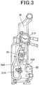
- Fig. 3 is a diagram showing the front frame 36 along with a peripheral configuration as viewed from a back side of Fig. 2 .
- a fuel pipe 26A extending from the fuel pump 31P is arranged on a back side of the front frame 36, and the fuel cock 21A is provided on the fuel pipe 26A.
- a valve stem of the fuel cock 21A penetrates through the front frame 36, and the operation knob 21 is coupled to a tip of the fuel cock 21A.
- the operation knob 21 rotates integrally with the fuel cock 21A.
- the fuel cock 21A is rotated and operated in a predetermined direction (clockwise in the present configuration) by the operation knob 21, and the fuel pipe 26A is switched from open to closed (the fuel cock 21A is switched from ON to OFF).
- the fuel cock 21A is rotated and operated in an opposite direction (counterclockwise in the present configuration) by the operation knob 21, and the fuel pipe 26A is switched from closed to open (the fuel cock 21A is switched from OFF to ON) .
- the engine switch 50 is a press type switch that switches on and off the engine 31, and as shown in Fig. 3 , the engine switch 50 is arranged at substantially the same height as the fuel cock 21A.
- the engine switch 50 includes a protrusion 50A protruding toward the fuel cock 21A, and the protrusion 50A is pressed to switch off the engine 31.
- the protrusion 50A is biased toward the fuel cock 21A by a biasing member (not shown) in the engine switch 50, and when the protrusion 50A is not pressed, the recoil starter 20 can start the engine 31 to continue the operation of the engine 31.
- the switch plate 40 is a link component that links the fuel cock 21A and the engine switch 50. The switch plate 40 will be described later.
- Fig. 4 is a diagram showing a link structure of the fuel cock 21A and the engine switch 50.
- the switch plate 40 is arranged on a back side of the operation knob 21 that rotates integrally with the fuel cock 21A.
- the switch plate 40 is supported by pin-shaped support members 52 arranged at an interval on the front and the back, and the switch plate 40 is movable toward the engine switch 50.
- a cam 22 that rotates integrally with the operation knob 21 is provided on the operation knob 21, and the cam 22 moves the switch plate 40 toward the engine switch 50 or toward the opposite side thereof.
- a movement direction when the switch plate 40 moves toward the engine switch 50 will be referred to as an X direction
- a movement direction when the switch plate 40 moves toward the opposite side of the engine switch 50 will be referred to as a Y direction.
- reference sign C1 denotes a shaft center common to the operation knob 21 and the fuel cock 21A (also coincides with the rotation center).
- the switch plate 40 will be described.
- Fig. 5 is a diagram showing the switch plate 40 along with a peripheral configuration. Note that in Fig. 5 , solid lines indicate the switch plate 40 and the cam 22 of Fig. 4 , and two-dot chain lines indicate the parts other than the cam 22 of the operation knob 21.
- the switch plate 40 includes: a recessed portion 41 recessed to allow the cam 22 of the operation knob 21 to enter; a first end portion 42 provided on an end portion in the X direction of the recessed portion 41; and a second end portion 43 provided on an end portion in the Y direction of the recessed portion 41, wherein the recessed portion 41, the first end portion 42, and the second end portion 43 are integrated with the switch plate 40.
- the switch plate 40 also includes guide grooves 44 in a long hole shape extending in the X and Y directions, the guide grooves 44 arranged at an interval on the front and the back.
- the support member 52 supported by the frame (the front frame 36 in the present configuration) of the power generation apparatus 1 is arranged on each of the guide grooves 44, and the guide grooves 44 and the support members 52 support the switch plate 40 such that the switch plate 40 is movable in the X and Y directions.
- Figs. 4 and 5 show a state in which the fuel cock 21A is rotated by the operation knob 21 toward the ON side (counterclockwise in Figs. 4 and 5 ) until the cam 22 abuts the second end portion 43 of the switch plate 40, and the switch plate 40 is moved in the Y direction to the greatest extent.
- the fuel cock 21A is fully open, and the engine switch 50 is also ON because the switch plate 40 does not press the engine switch 50. Therefore, in the switch plate 40, the second end portion 43 forms an area in which the fuel cock 21A is fully open, and the cam 22 comes into contact while the engine switch 50 is at the ON position.
- the recessed portion 41 forms a movement area of the cam 22 while the fuel cock 21A is switched on or off.
- the recessed portion 41 is formed in a recessed shape that prevents the switch plate 40 from moving to the position for pressing the protrusion 50A of the engine switch 50 while the cam 22 moves in the area equivalent to the recessed portion 41.
- the recessed portion 41 is formed in a recessed shape extending in the circumferential direction of the operation knob 21, outside of the operation knob 21 in the radial direction with respect to the moving cam 22, to hold the switch plate 40 at a position not pressing the protrusion 50A of the engine switch 50.
- the outside of the operation knob 21 in the radial direction coincides with the outside of the fuel cock 21A in the radial direction
- the circumferential direction of the operation knob 21 coincides with the circumferential direction of the fuel cock 21A.
- the engine switch is held in the ON state while the fuel cock 21A is switched on or off by the operation knob 21.
- the first end portion 42 forms a contact area (movement area) of the cam 22 while the fuel cock 21A further rotates in the OFF state after the fuel cock 21A is switched off.
- the first end portion 42 includes a cam contact wall 45 that is an inclined wall extending inside of the operation knob 21 in the radial direction from a retracted position outside of the operation knob 21 in the radial direction with respect to the cam 22 after the fuel cock 21A is switched off.
- the cam 22 of the fuel cock 21A in the OFF state comes into contact with the cam contact wall 45, and the cam 22 also comes into contact with the cam contact wall 45 while the fuel cock 21A is further rotated (rotated clockwise) in the OFF state. Since the cam contact wall 45 extends inside of the operation knob 21 in the radial direction with respect to the cam 22, the cam contact wall 45 forms a step that the cam 22 moving in the rotation direction of the operation knob 21 climbs over. Therefore, the amount of the cam 22 pushing out the cam contact wall 45 in the X direction can be large even if a turn angle of the operation knob 21 is relatively small. As a result, an extending portion 46 described later of the switch plate 40 can switch off the engine switch 50 at once with a small turn angle.
- the extending portion 46 described later of the switch plate 40 abuts the protrusion 50A of the engine switch 50 while the cam 22 is in contact with the cam contact wall 45. Therefore, the force biasing the protrusion 50A in the Y direction acts as force (reaction force) pressing the cam contact wall 45 against the cam 22, and the operation knob 21 needs to be rotated clockwise against the biasing force. Therefore, the rotational resistance (equivalent to force required for clockwise rotation) of the operation knob 21 further increases by the amount of the biasing force of the protrusion 50A.
- change characteristics such as strength of the rotational resistance of the operation knob 21 caused by the cam contact wall 45, that is, change characteristics of the force required for the rotation operation of the fuel cock 21A, can be easily adjusted by adjusting the inclined angle of the cam contact wall 45 or by changing the shape of the inclination.
- the first end portion 42 includes the extending portion 46 extending from the cam contact wall 45 toward the protrusion 50A of the engine switch 50.
- the extending portion 46 is moved by the cam 22 toward the engine switch 50 to press the protrusion 50A of the engine switch 50 in the X direction when the fuel cock 21A further rotates beyond the OFF position from the state in which the cam 22 is brought into contact with the cam contact wall 45 by the operation knob 21 (see Fig. 6C described later). Therefore, the extending portion 46 functions as a switch operation portion that turns off the engine switch 50 according to the movement of the cam 22.
- a resin material is used to manufacture the switch plate 40 by integral molding.
- a hollow is provided inside of the switch plate 40 as shown in Fig. 5 , and the weight of the entire switch plate 40 is reduced.
- the switch plate 40 is also provided with a rib 45R in an area of the cam contact wall 45, and the rib 45R reinforces the cam contact wall 45.
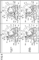
- Figs. 6A to 6C show a case in which the fuel cock 21A is further rotated and operated by the operation knob 21 beyond the OFF position from the ON position.
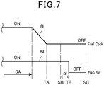
- Fig. 7 is a diagram showing changes in ON (ON in Fig. 7 ) and OFF (OFF in Fig. 7 ) of the fuel cock 21A and the engine switch 50. Note that in Fig. 7 , reference sign f1 denotes a characteristic curve of the fuel cock 21A, and reference sign f2 shows a characteristic curve of the engine switch 50.
- the extending portion 46 of the switch plate 40 abuts the protrusion 50A of the engine switch 50 in the case of the state SB. Therefore, the fuel cock 21A needs to be rotated against the biasing force of the protrusion 50A.
- the rotational resistance of the fuel cock 21A further increases by the amount of the biasing force, and the force required for the operation of the fuel cock 21A further increases.
- the engine switch 50 is switched from ON to OFF by the extending portion 46 of the switch plate 40 at a timing TB just after the state SB, and the click feeling can be provided between the state SB and the timing TB (indicated by reference sign ⁇ in Fig. 7 ).
- the user can easily recognize that the fuel cock 21A is switched off while the engine switch 50 is ON.
- the reaction force from the protrusion 50A acts as force that restricts the rotation of the fuel cock 21A through the cam 22, and the fuel cock 21A and the engine switch 50 are held in the OFF state.
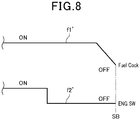
- Fig. 8 shows a reference example of a configuration in which the engine switch 50 is switched from ON to OFF while the fuel cock 21A is switched from ON to OFF.
- reference sign f1' shows a characteristic curve of the fuel cock 21A
- reference sign f2' shows a characteristic curve of the engine switch 50.
- the fuel cock 21A is switched off after the engine switch 50 is switched off. Therefore, the fuel remaining between the fuel cock 21A and the carburetor 34 cannot be used to operate the engine 31.
- the engine switch 50 is ON at the position where the fuel cock 21A is switched from ON to OFF as shown in Fig. 7 . Therefore, the operation of the engine 31 can be continued even when the fuel cock 21A is at the OFF position. As a result, the fuel remaining between the fuel cock 21A and the carburetor 34 can be used to operate the engine 31.
- the user can have the operation feeling that allows recognizing that the fuel cock 21A is switched off while the engine switch 50 is in the ON state. Therefore, the user can easily recognize whether the fuel cock 21A is ON or OFF. As a result, the fuel remaining between the fuel cock 21A and the carburetor 34 can be easily used up, and the toughness against a poor start caused by a deterioration of fuel can be improved.
- the cam 22 and the switch plate 40 link the fuel cock 21A and the engine switch 50. Therefore, the number of components can be small, and this can reduce the complication of the structure, the increase in the weight, and the increase in the size.
- Fig. 9 is a diagram illustrating a comparative example showing another arrangement of the switch plate 40 and the engine switch 50 and an arrangement configuration of the present embodiment.
- the comparative example shown in Fig. 9 is different in that the position of the protrusion 50A of the engine switch 50 is a position lower than in the present embodiment.
- the switch plate 40 abuts the protrusion 50A in the state SC. Therefore, a moment MR that rotates the fuel cock 21A toward the ON side (counterclockwise in Fig. 9 ) is generated by reaction force FC1 acting from the protrusion 50A.
- the position of the gap (gaps SU and SL) between the support member 52 and the guide groove 44 changes upward and downward between the states SB and SC, and therefore, there is up and down motion of the switch plate 40.
- the switch plate 40 moves toward the engine switch 50, vibration is generated in the perpendicular direction relative to the movement direction (X direction) in the comparative example.
- a moment MF2 that rotates the fuel cock 21A toward the OFF side is generated by reaction force FC2 of the action of the switch plate 40 from the protrusion 50A in the state SC as shown in Fig. 9 .
- FC2 reaction force
- the position of the gap (gap SU) between the support member 52 and the guide groove 44 is the same position in the states SB and SC in the present embodiment, and there is no up and down motion of the switch plate 40.
- the switch plate 40 moves toward the engine switch 50, there is no vibration in the perpendicular direction relative to the movement direction (X direction), and the switch plate 40 can be smoothly moved.
- the switch plate 40 (link component) that links the fuel cock 21A and the engine switch 50 is provided in the configuration of the present embodiment, and under the configuration, the switch plate 40 is configured as follows.
- the switch plate 40 includes: the extending portion 46 (switch operation portion) that is pressed by the cam 22 rotating integrally with the fuel cock 21A to switch off the engine switch 50 when the fuel cock 21A is further rotated beyond the position where the fuel cock 21A is switched from ON to OFF; and the cam contact wall 45 where the cam 22 comes into contact to change the rotational resistance of the fuel cock 21A to allow providing the operation feeling equivalent to the click feeling when the fuel cock 21A is further rotated beyond the position where the fuel cock 21A is switched from ON to OFF.
- the power transmission between the fuel cock 21A and the engine switch 50 can be realized just by the switch plate 40, and the number of components can be smaller than in the conventional configuration including a link mechanism and a notch mechanism. This can reduce the complication of the structure, the increase in the weight, and the increase in the size.
- the operation of the engine 31 can be continued even when the fuel cock 21A is at the OFF position.
- the engine switch 50 can be turned off with a small turn angle of the fuel cock 21A from the OFF position, and the user can easily recognize whether the fuel cock 21A is ON or OFF. Therefore, the fuel cock 21A and the engine switch 50 can be linked with a simple configuration, and the residual fuel can be easily reduced.
- the cam contact wall 45 is formed by the inclined wall extending inside of the fuel cock 21A in the radial direction from the retracted position outside of the fuel cock 21A in the radial direction with respect to the cam 22 at the time that the fuel cock 21A is switched off.
- the click feeling can be provided with a simple configuration, and the operation feeling of the fuel cock 21A can be easily adjusted by shape adjustment of the inclined angle of the cam contact wall 45 or the like.
- the shape is not limited to the shape providing the click feeling, and the shape may be changed to a shape providing another operation feeling.
- the contact position of the engine switch 50 and the extending portion 46 of the switch plate 40 is set such that the moment MF2 acting on the switch plate 40 from the engine switch 50 through the extending portion 46 after the press of the engine switch 50 acts in the same direction as the moment MF1 (state SB in Fig 9 ) acting on the switch plate 40 when the cam 22 comes into contact with the cam contact wall 45 after the rotation of the fuel cock 21A toward the OFF side.
- the force generated by the moments MF1 and MF2 can act on the switch plate 40 in the same direction, and unnecessary motion (up and down motion in the present configuration) of the switch plate 40 can be prevented.
- the switch plate 40 is guided such that the switch plate 40 is movable toward the side in which the extending portion 46 (switch operation portion) switches off the engine switch 50. Therefore, the motion in directions other than the guided direction can be prevented, and the movement of the switch plate 40 can be smooth.
- the embodiment is just a mode for carrying out the present invention, and the embodiment can be arbitrarily modified and applied without departing from the scope of the present invention.
- the shapes of the switch plate 40 and the cam 22 are not limited to the shapes, and the shapes may be appropriately changed.
- the movement direction of the switch plate 40 is not limited to the horizontal direction, and the movement direction may be appropriately changed to the vertical direction or the like.
- the arrangement relationship between the switch plate 40 and the engine switch 50 may also be appropriately changed.
- the engine switch 50 may be various well-known switches that can be turned on and off by the switch plate 40, and the engine switch 50 may not be limited to the press type.
- the fuel of the engine 31 is liquid fuel in the case described in the embodiment, the fuel is not limited to this, and the fuel may be gas fuel, such as LP gas.
- a gas supply port can be provided in place of the fuel tank 30, or a cassette gas can be arranged.
- the present invention is applied to the link structure applied to the power generation apparatus 1 in the described case, the present invention is not limited to this.
- the present invention can be widely applied to various well-known apparatuses including the fuel cock 21A and the engine switch 50.
- a switch plate (40) (link component) that links a fuel cock (21A) and an engine switch (50) is provided.
- the switch plate (40) includes: an extending portion (46) (switch operation portion) pressed by a cam (22), which rotates integrally with the fuel cock (21A), to switch off the engine switch (50) when the fuel cock (21A) is further rotated beyond a position where the fuel cock (21A) is switched from ON to OFF; and a cam contact wall (45) where the cam (22) comes into contact to change rotational resistance of the fuel cock (21A) to allow providing a predetermined operation feeling when the fuel cock (21A) further rotates beyond the position where the fuel cock (21A) is switched from ON to OFF.
Landscapes
- Engineering & Computer Science (AREA)
- Chemical & Material Sciences (AREA)
- Combustion & Propulsion (AREA)
- Mechanical Engineering (AREA)
- General Engineering & Computer Science (AREA)
- Rotary Switch, Piano Key Switch, And Lever Switch (AREA)
- Control Of Throttle Valves Provided In The Intake System Or In The Exhaust System (AREA)
- Output Control And Ontrol Of Special Type Engine (AREA)
Abstract
Description
- The present invention relates to a link structure of a fuel cock and an engine switch.
- A configuration of using a plurality of shafts coupled in a bendable manner to transmit power between a fuel cock and an engine switch and a configuration of using a link mechanism to transmit power are known as link structures of the fuel cock and the engine switch (for example, see Japanese Utility Model Publication Nos.
64-47948 2005-105971 - A fuel cock integrated with an engine switch so as to open and close a contact point in conjunction with a rotation operation of a lever of the fuel cock is known as this type of link structure (for example, see Japanese Patent Laid-Open No.
2004-293475 2004-293475 - However, the numbers of components are large in the conventional configurations. This complicates the structure and causes an increase in the weight or an increase in the size. While the conventional configurations can prevent the fuel cock from being left open when the engine switch is OFF, it is difficult to use up the fuel remaining between the fuel cock and a carburetor. When the fuel remains for a long time, the fuel is deteriorated, and this causes a poor start.
- Accordingly, an object of the present invention is to allow linking a fuel cock and an engine switch with a simple configuration and reducing residual fuel.
- To attain the object, the present invention provides a link structure of a fuel cock and an engine switch, the link structure including: a cam that rotates integrally with the fuel cock; and a link component that links the fuel cock and the engine switch, the link component including: a switch operation portion pressed by the cam to switch off the engine switch when the fuel cock is further rotated beyond a position where the fuel cock is switched from ON to OFF; and a cam contact wall where the cam comes into contact to change rotational resistance of the fuel cock to allow providing a predetermined operation feeling when the fuel cock is further rotated beyond the position where the fuel cock is switched from ON to OFF.
- According to the configuration, the power transmission between the fuel cock and the engine switch can be realized only by the link component, and the number of components can be reduced. The operation of the engine can be continued even when the fuel cock is at the OFF position. In addition, the engine switch can be turned off with a small turn angle of the fuel cock from the OFF position, and the user can easily recognize whether the fuel cock is ON or OFF.
- In the configuration, the cam contact wall is an inclined wall extending inside of the fuel cock in a radial direction from a retracted position outside of the fuel cock in the radial direction with respect to the cam at the time that the fuel cock is switched off.
- According to the configuration, an operation feeling equivalent to a click feeling can be provided with a simple configuration. Furthermore, the operation feeling of the fuel cock can be easily adjusted by shape adjustment of an inclined angle of the cam contact wall or the like.
- In the configuration, the engine switch is a press type, and a contact position of the engine switch and the switch operation portion is set such that a moment acting on the link component from the engine switch through the switch operation portion after a press of the engine switch acts in a same direction as a moment acting on the link component when the cam comes into contact with the cam contact wall after rotation of the fuel cock toward an OFF side.
- According to the configuration, the force generated by the moments can act on the link component in the same direction, and unnecessary motion of the link component can be prevented.
- In the configuration, the link component is guided such that the link component is movable toward a side in which the switch operation portion switches off the engine switch. According to the configuration, motion in directions other than the guided direction can be prevented, and the movement of the link component can be smooth.
- According to the present invention, the fuel cock and the engine switch can be linked with a simple configuration, and residual fuel can be easily reduced.
-
-
Fig. 1 is a perspective view showing an appearance of a power generation apparatus applying a link mechanism according to an embodiment of the present invention; -
Fig. 2 is a diagram in which a housing is removed from the power generation apparatus; -
Fig. 3 is a diagram showing a front frame of the power generation apparatus along with a peripheral configuration as viewed from a back side ofFig. 2 ; -
Fig. 4 is a diagram showing a link structure of a fuel cock and an engine switch; -
Fig. 5 is a diagram showing a switch plate along with a peripheral configuration; -
Fig. 6A is a diagram showing a state in which the fuel cock is rotated and operated to an ON position and to a fully open position; -
Fig. 6B is a diagram showing a state in which a cam of the fuel cock comes into contact with a cam contact wall; -
Fig. 6C is a diagram showing a state in which the fuel cock is further rotated from the state in which the cam is in contact with the cam contact wall; -
Fig. 7 is a diagram showing changes in ON/OFF of the fuel cock and the engine switch; -
Fig. 8 is a diagram showing changes in ON/OFF of a fuel cock and an engine switch in a reference example; and -
Fig. 9 is a diagram illustrating arrangement configurations of a comparative example and the present embodiment. - An embodiment of the present invention will now be described with reference to the drawings.
-
Fig. 1 is a perspective view showing an appearance of apower generation apparatus 1 applying a link structure according to the embodiment of the present invention. - As shown in
Fig. 1 , thepower generation apparatus 1 includes ahousing 10 that is a substantially rectangular solid, and acontrol panel 11 is installed on a side surface of thehousing 10. Hereinafter, the surface provided with thecontrol panel 11 will be referred to as a front surface. - Various terminals, such as a
power outlet 12, and various operation switches, such as afrequency selector switch 13, and the like are provided on thecontrol panel 11. Aremovable cover 14 is provided on a left side surface positioned on the left with reference to the front surface of thehousing 10, and thecover 14 can be removed to access the inside of thehousing 10. - A
recoil starter 20 and a rotary fuel cock operation knob 21 (hereinafter, referred to as an operation knob 21) are exposed to the outside and provided on the left side surface of thehousing 10, and therecoil starter 20 and theoperation knob 21 can be operated from the outside. Ahandle 25 is provided on an upper surface of thehousing 10, and afuel cap 26 is exposed on a front surface side of thehandle 25. Thefuel cap 26 can be removed to supply fuel to afuel tank 30 descried later (Fig. 2 described later) in thepower generation apparatus 1. A plurality oflegs 27 that support thehousing 10 are attached to a lower surface of thehousing 10. -
Fig. 2 is a diagram in which thehousing 10 is removed from thepower generation apparatus 1. Note that a right direction in the drawing ofFig. 2 is equivalent to a front surface side of thepower generation apparatus 1, and a left direction in the drawing is equivalent to a back surface side of thepower generation apparatus 1. - The
power generation apparatus 1 is provided with anengine 31 on a lower part near the back surface of thehousing 10, and anair cleaner 33 and acarburetor 34 are arranged around theengine 31. Thefuel tank 30 is arranged on an upper part near the front surface of thehousing 10, and therecoil starter 20, an engine switch plate 40 (hereinafter, referred to as a switch plate 40), an engine switch 50 (Fig. 3 described later), and the like are arranged below thefuel tank 30. - The
engine 31 is an internal combustion engine that uses gasoline as a fuel. An alternator not shown uses power of theengine 31 to generate electricity, and an inverter not shown converts the generated electricity into predetermined electric power. The electric power is supplied to thepower outlet 12 and the like. A fuel pipe 35 (Fig. 3 ) extending from afuel pump 31P (Fig. 3 ) is connected to thecarburetor 34, and thefuel pump 31P supplies the fuel in thefuel tank 30 to thecarburetor 34. Thecarburetor 34 supplies air cleaned by theair cleaner 33 and the fuel to theengine 31. - Note that the fuel of the
engine 31 is not limited to gasoline, and the fuel may be other liquid fuel. - As shown in
Fig. 2 , a plate-like front frame (frame member) 36 extending in an up and down direction on the side of thefuel tank 30 is provided on the front side of thepower generation apparatus 1. Afuel cock 21A, theswitch plate 40, theengine switch 50, and the like are supported by thefront frame 36. -
Fig. 3 is a diagram showing thefront frame 36 along with a peripheral configuration as viewed from a back side ofFig. 2 . - A
fuel pipe 26A extending from thefuel pump 31P is arranged on a back side of thefront frame 36, and thefuel cock 21A is provided on thefuel pipe 26A. A valve stem of thefuel cock 21A penetrates through thefront frame 36, and theoperation knob 21 is coupled to a tip of thefuel cock 21A. - The
operation knob 21 rotates integrally with thefuel cock 21A. Thefuel cock 21A is rotated and operated in a predetermined direction (clockwise in the present configuration) by theoperation knob 21, and thefuel pipe 26A is switched from open to closed (thefuel cock 21A is switched from ON to OFF). Thefuel cock 21A is rotated and operated in an opposite direction (counterclockwise in the present configuration) by theoperation knob 21, and thefuel pipe 26A is switched from closed to open (thefuel cock 21A is switched from OFF to ON) . - The
engine switch 50 is a press type switch that switches on and off theengine 31, and as shown inFig. 3 , theengine switch 50 is arranged at substantially the same height as thefuel cock 21A. Theengine switch 50 includes aprotrusion 50A protruding toward thefuel cock 21A, and theprotrusion 50A is pressed to switch off theengine 31. - The
protrusion 50A is biased toward thefuel cock 21A by a biasing member (not shown) in theengine switch 50, and when theprotrusion 50A is not pressed, therecoil starter 20 can start theengine 31 to continue the operation of theengine 31. Theswitch plate 40 is a link component that links thefuel cock 21A and theengine switch 50. Theswitch plate 40 will be described later. -
Fig. 4 is a diagram showing a link structure of thefuel cock 21A and theengine switch 50. - As shown in
Fig. 4 , theswitch plate 40 is arranged on a back side of theoperation knob 21 that rotates integrally with thefuel cock 21A. Theswitch plate 40 is supported by pin-shapedsupport members 52 arranged at an interval on the front and the back, and theswitch plate 40 is movable toward theengine switch 50. Acam 22 that rotates integrally with theoperation knob 21 is provided on theoperation knob 21, and thecam 22 moves theswitch plate 40 toward theengine switch 50 or toward the opposite side thereof. - Hereinafter, a movement direction when the
switch plate 40 moves toward theengine switch 50 will be referred to as an X direction, and a movement direction when theswitch plate 40 moves toward the opposite side of theengine switch 50 will be referred to as a Y direction. In each of the drawings includingFig. 4 , reference sign C1 denotes a shaft center common to theoperation knob 21 and thefuel cock 21A (also coincides with the rotation center). - The
switch plate 40 will be described. -
Fig. 5 is a diagram showing theswitch plate 40 along with a peripheral configuration. Note that inFig. 5 , solid lines indicate theswitch plate 40 and thecam 22 ofFig. 4 , and two-dot chain lines indicate the parts other than thecam 22 of theoperation knob 21. - The
switch plate 40 includes: a recessedportion 41 recessed to allow thecam 22 of theoperation knob 21 to enter; afirst end portion 42 provided on an end portion in the X direction of the recessedportion 41; and asecond end portion 43 provided on an end portion in the Y direction of the recessedportion 41, wherein the recessedportion 41, thefirst end portion 42, and thesecond end portion 43 are integrated with theswitch plate 40. - The
switch plate 40 also includesguide grooves 44 in a long hole shape extending in the X and Y directions, theguide grooves 44 arranged at an interval on the front and the back. Thesupport member 52 supported by the frame (thefront frame 36 in the present configuration) of thepower generation apparatus 1 is arranged on each of theguide grooves 44, and theguide grooves 44 and thesupport members 52 support theswitch plate 40 such that theswitch plate 40 is movable in the X and Y directions. -
Figs. 4 and5 show a state in which thefuel cock 21A is rotated by theoperation knob 21 toward the ON side (counterclockwise inFigs. 4 and5 ) until thecam 22 abuts thesecond end portion 43 of theswitch plate 40, and theswitch plate 40 is moved in the Y direction to the greatest extent. In this state, thefuel cock 21A is fully open, and theengine switch 50 is also ON because theswitch plate 40 does not press theengine switch 50. Therefore, in theswitch plate 40, thesecond end portion 43 forms an area in which thefuel cock 21A is fully open, and thecam 22 comes into contact while theengine switch 50 is at the ON position. - In the
switch plate 40, the recessedportion 41 forms a movement area of thecam 22 while thefuel cock 21A is switched on or off. The recessedportion 41 is formed in a recessed shape that prevents theswitch plate 40 from moving to the position for pressing theprotrusion 50A of theengine switch 50 while thecam 22 moves in the area equivalent to the recessedportion 41. - More specifically, the recessed
portion 41 is formed in a recessed shape extending in the circumferential direction of theoperation knob 21, outside of theoperation knob 21 in the radial direction with respect to the movingcam 22, to hold theswitch plate 40 at a position not pressing theprotrusion 50A of theengine switch 50. Note that the outside of theoperation knob 21 in the radial direction coincides with the outside of thefuel cock 21A in the radial direction, and the circumferential direction of theoperation knob 21 coincides with the circumferential direction of thefuel cock 21A. - As a result, the engine switch is held in the ON state while the
fuel cock 21A is switched on or off by theoperation knob 21. - In the
switch plate 40, thefirst end portion 42 forms a contact area (movement area) of thecam 22 while thefuel cock 21A further rotates in the OFF state after thefuel cock 21A is switched off. Thefirst end portion 42 includes acam contact wall 45 that is an inclined wall extending inside of theoperation knob 21 in the radial direction from a retracted position outside of theoperation knob 21 in the radial direction with respect to thecam 22 after thefuel cock 21A is switched off. - The
cam 22 of thefuel cock 21A in the OFF state comes into contact with thecam contact wall 45, and thecam 22 also comes into contact with thecam contact wall 45 while thefuel cock 21A is further rotated (rotated clockwise) in the OFF state. Since thecam contact wall 45 extends inside of theoperation knob 21 in the radial direction with respect to thecam 22, thecam contact wall 45 forms a step that thecam 22 moving in the rotation direction of theoperation knob 21 climbs over. Therefore, the amount of thecam 22 pushing out thecam contact wall 45 in the X direction can be large even if a turn angle of theoperation knob 21 is relatively small. As a result, an extendingportion 46 described later of theswitch plate 40 can switch off theengine switch 50 at once with a small turn angle. - In this case, since the
cam 22 pushes out thecam contact wall 45 in the X direction with a small turn angle, the frictional force between thecam 22 and theswitch plate 40 increases, and the rotational resistance (equivalent to force required for clockwise rotation) of theoperation knob 21 increases. - As shown in
Fig. 6B described later, the extendingportion 46 described later of theswitch plate 40 abuts theprotrusion 50A of theengine switch 50 while thecam 22 is in contact with thecam contact wall 45. Therefore, the force biasing theprotrusion 50A in the Y direction acts as force (reaction force) pressing thecam contact wall 45 against thecam 22, and theoperation knob 21 needs to be rotated clockwise against the biasing force. Therefore, the rotational resistance (equivalent to force required for clockwise rotation) of theoperation knob 21 further increases by the amount of the biasing force of theprotrusion 50A. - When the
cam 22 climbs over the step generated by thecam contact wall 45, the increase in the rotation resistance of theoperation knob 21 stops. As a result, an operation feeling equivalent to a click feeling is provided. - Note that change characteristics, such as strength of the rotational resistance of the
operation knob 21 caused by thecam contact wall 45, that is, change characteristics of the force required for the rotation operation of thefuel cock 21A, can be easily adjusted by adjusting the inclined angle of thecam contact wall 45 or by changing the shape of the inclination. - The
first end portion 42 includes the extendingportion 46 extending from thecam contact wall 45 toward theprotrusion 50A of theengine switch 50. The extendingportion 46 is moved by thecam 22 toward theengine switch 50 to press theprotrusion 50A of theengine switch 50 in the X direction when thefuel cock 21A further rotates beyond the OFF position from the state in which thecam 22 is brought into contact with thecam contact wall 45 by the operation knob 21 (seeFig. 6C described later). Therefore, the extendingportion 46 functions as a switch operation portion that turns off theengine switch 50 according to the movement of thecam 22. - A resin material is used to manufacture the
switch plate 40 by integral molding. In this case, a hollow is provided inside of theswitch plate 40 as shown inFig. 5 , and the weight of theentire switch plate 40 is reduced. Theswitch plate 40 is also provided with arib 45R in an area of thecam contact wall 45, and therib 45R reinforces thecam contact wall 45. - Next, an operation of the link structure of the
fuel cock 21A and theengine switch 50 will be described. -
Figs. 6A to 6C show a case in which thefuel cock 21A is further rotated and operated by theoperation knob 21 beyond the OFF position from the ON position.Fig. 7 is a diagram showing changes in ON (ON inFig. 7 ) and OFF (OFF inFig. 7 ) of thefuel cock 21A and theengine switch 50. Note that inFig. 7 , reference sign f1 denotes a characteristic curve of thefuel cock 21A, and reference sign f2 shows a characteristic curve of theengine switch 50. - As shown in
Fig. 6A , when thefuel cock 21A is rotated and operated by theoperation knob 21 to the ON position and to the fully open position, thecam 22 comes into contact with thesecond end portion 43 of theswitch plate 40. In this case, theswitch plate 40 is at a position retracted to the greatest extent from theengine switch 50, and theengine switch 50 is ON. The state in which both thefuel cock 21A and theengine switch 50 are ON will be referred to as a state SA (seeFig. 7 ). - When the
fuel cock 21A is rotated and operated by theoperation knob 21 toward the OFF side from the state SA, thecam 22 abuts thecam contact wall 45 of thefirst end portion 42 of theswitch plate 40 as shown inFig. 6B . The state shown inFig. 6B will be referred to as a state SB. - As shown in
Fig. 7 , there is a timing TA that thefuel cock 21A is switched from ON to OFF between the state SA and the state SB. Therefore, thefuel cock 21A is OFF, and theengine switch 50 is ON in the state SB. - In the state SB, the
cam 22 abuts thecam contact wall 45 as shown inFig. 6B . Therefore, when thefuel cock 21A is further rotated clockwise by theoperation knob 21, a large amount of movement of theswitch plate 40 can be secured even if the turn angle of thefuel cock 21A is small. As a result, theengine switch 50 can be switched off with a small turn angle after thefuel cock 21A is turned off. - Since the
cam 22 abuts thecam contact wall 45, the frictional resistance between thecam 22 and thecam contact wall 45 increases when thefuel cock 21A is further rotated clockwise by theoperation knob 21. As a result, the rotational resistance in rotating thefuel cock 21A increases, and the force required for the operation of thefuel cock 21A increases. - Moreover, the extending
portion 46 of theswitch plate 40 abuts theprotrusion 50A of theengine switch 50 in the case of the state SB. Therefore, thefuel cock 21A needs to be rotated against the biasing force of theprotrusion 50A. The rotational resistance of thefuel cock 21A further increases by the amount of the biasing force, and the force required for the operation of thefuel cock 21A further increases. - Once the
fuel cock 21A is rotated and operated by theoperation knob 21 against the biasing force of the extendingportion 46, the increase in the rotational resistance of thefuel cock 21A stops when thecam 22 climbs over thecam contact wall 45. - In this way, the rotational resistance of the
fuel cock 21A is changed from increase to decrease in a short time along with the clockwise rotation of thefuel cock 21A starting from the state SB. This allows the user to recognize a so-called one click feeling. - As shown in
Fig. 7 , theengine switch 50 is switched from ON to OFF by the extendingportion 46 of theswitch plate 40 at a timing TB just after the state SB, and the click feeling can be provided between the state SB and the timing TB (indicated by reference sign α inFig. 7 ). As a result, the user can easily recognize that thefuel cock 21A is switched off while theengine switch 50 is ON. - When the
fuel cock 21A is further rotated and operated by theoperation knob 21 beyond the OFF position from the timing TB, thecam 22 climbs over thecam contact wall 45 of theswitch plate 40 as shown inFig. 6C . The state shown inFig. 6C will be referred to as a state SC. - In the state SC, the reaction force from the
protrusion 50A acts as force that restricts the rotation of thefuel cock 21A through thecam 22, and thefuel cock 21A and theengine switch 50 are held in the OFF state. - Here,
Fig. 8 shows a reference example of a configuration in which theengine switch 50 is switched from ON to OFF while thefuel cock 21A is switched from ON to OFF. InFig. 8 , reference sign f1' shows a characteristic curve of thefuel cock 21A, and reference sign f2' shows a characteristic curve of theengine switch 50. - According to the reference example, the
fuel cock 21A is switched off after theengine switch 50 is switched off. Therefore, the fuel remaining between thefuel cock 21A and thecarburetor 34 cannot be used to operate theengine 31. - On the other hand, in the present configuration, the
engine switch 50 is ON at the position where thefuel cock 21A is switched from ON to OFF as shown inFig. 7 . Therefore, the operation of theengine 31 can be continued even when thefuel cock 21A is at the OFF position. As a result, the fuel remaining between thefuel cock 21A and thecarburetor 34 can be used to operate theengine 31. - Moreover, the user can have the operation feeling that allows recognizing that the
fuel cock 21A is switched off while theengine switch 50 is in the ON state. Therefore, the user can easily recognize whether thefuel cock 21A is ON or OFF. As a result, the fuel remaining between thefuel cock 21A and thecarburetor 34 can be easily used up, and the toughness against a poor start caused by a deterioration of fuel can be improved. - Furthermore, the
cam 22 and theswitch plate 40 link thefuel cock 21A and theengine switch 50. Therefore, the number of components can be small, and this can reduce the complication of the structure, the increase in the weight, and the increase in the size. - Next, an arrangement of the
switch plate 40 and theengine switch 50 will be described. -
Fig. 9 is a diagram illustrating a comparative example showing another arrangement of theswitch plate 40 and theengine switch 50 and an arrangement configuration of the present embodiment. - The comparative example shown in
Fig. 9 is different in that the position of theprotrusion 50A of theengine switch 50 is a position lower than in the present embodiment. - In the comparative example, the
switch plate 40 abuts theprotrusion 50A in the state SC. Therefore, a moment MR that rotates thefuel cock 21A toward the ON side (counterclockwise inFig. 9 ) is generated by reaction force FC1 acting from theprotrusion 50A. - The moment MR moves the
switch plate 40 downward as shown inFig. 9 , and internalupper surfaces 44U of theguide grooves 44 of theswitch plate 40 abut upper ends of thesupport members 52. Therefore, a gap SL is formed between a lower end of thesupport member 52 and an internallower surface 44L of theguide groove 44. - On the other hand, in the state SB, the
engine switch 50 and theswitch plate 40 are separated both in the comparative example and the present embodiment. Therefore, upward force FB indicated by an arrow FB inFig. 9 is generated in theswitch plate 40 due to abutment force of thecam 22 and thecam contact wall 45. The force FB generates a moment MF1 that rotates thefuel cock 21A clockwise. - The moment MF1 moves the
switch plate 40 upward, and the internallower surfaces 44L of theguide grooves 44 of theswitch plate 40 abut the lower ends of thesupport members 52. Therefore, a gap SU is formed between the upper end of thesupport member 52 and the internalupper surface 44U of theguide groove 44. - In this way, in the comparative example, the position of the gap (gaps SU and SL) between the
support member 52 and theguide groove 44 changes upward and downward between the states SB and SC, and therefore, there is up and down motion of theswitch plate 40. As a result, when theswitch plate 40 moves toward theengine switch 50, vibration is generated in the perpendicular direction relative to the movement direction (X direction) in the comparative example. - On the other hand, in the present embodiment, a moment MF2 that rotates the
fuel cock 21A toward the OFF side (clockwise inFig. 9 ) is generated by reaction force FC2 of the action of theswitch plate 40 from theprotrusion 50A in the state SC as shown inFig. 9 . Note that only the part that the reaction force FC2 acts on theswitch plate 40 is different from the reaction force FC1. - Therefore, the position of the gap (gap SU) between the
support member 52 and theguide groove 44 is the same position in the states SB and SC in the present embodiment, and there is no up and down motion of theswitch plate 40. As a result, when theswitch plate 40 moves toward theengine switch 50, there is no vibration in the perpendicular direction relative to the movement direction (X direction), and theswitch plate 40 can be smoothly moved. - As described, the switch plate 40 (link component) that links the
fuel cock 21A and theengine switch 50 is provided in the configuration of the present embodiment, and under the configuration, theswitch plate 40 is configured as follows. - The
switch plate 40 includes: the extending portion 46 (switch operation portion) that is pressed by thecam 22 rotating integrally with thefuel cock 21A to switch off theengine switch 50 when thefuel cock 21A is further rotated beyond the position where thefuel cock 21A is switched from ON to OFF; and thecam contact wall 45 where thecam 22 comes into contact to change the rotational resistance of thefuel cock 21A to allow providing the operation feeling equivalent to the click feeling when thefuel cock 21A is further rotated beyond the position where thefuel cock 21A is switched from ON to OFF. - According to the configuration, the power transmission between the
fuel cock 21A and theengine switch 50 can be realized just by theswitch plate 40, and the number of components can be smaller than in the conventional configuration including a link mechanism and a notch mechanism. This can reduce the complication of the structure, the increase in the weight, and the increase in the size. - Furthermore, the operation of the
engine 31 can be continued even when thefuel cock 21A is at the OFF position. In addition, theengine switch 50 can be turned off with a small turn angle of thefuel cock 21A from the OFF position, and the user can easily recognize whether thefuel cock 21A is ON or OFF. Therefore, thefuel cock 21A and theengine switch 50 can be linked with a simple configuration, and the residual fuel can be easily reduced. - Furthermore, the
cam contact wall 45 is formed by the inclined wall extending inside of thefuel cock 21A in the radial direction from the retracted position outside of thefuel cock 21A in the radial direction with respect to thecam 22 at the time that thefuel cock 21A is switched off. According to the configuration, the click feeling can be provided with a simple configuration, and the operation feeling of thefuel cock 21A can be easily adjusted by shape adjustment of the inclined angle of thecam contact wall 45 or the like. For example, the shape is not limited to the shape providing the click feeling, and the shape may be changed to a shape providing another operation feeling. - In the present configuration, as shown in the state SC of
Fig. 9 , the contact position of theengine switch 50 and the extendingportion 46 of theswitch plate 40 is set such that the moment MF2 acting on theswitch plate 40 from theengine switch 50 through the extendingportion 46 after the press of theengine switch 50 acts in the same direction as the moment MF1 (state SB inFig 9 ) acting on theswitch plate 40 when thecam 22 comes into contact with thecam contact wall 45 after the rotation of thefuel cock 21A toward the OFF side. - According to the configuration, the force generated by the moments MF1 and MF2 can act on the
switch plate 40 in the same direction, and unnecessary motion (up and down motion in the present configuration) of theswitch plate 40 can be prevented. - Furthermore, the
switch plate 40 is guided such that theswitch plate 40 is movable toward the side in which the extending portion 46 (switch operation portion) switches off theengine switch 50. Therefore, the motion in directions other than the guided direction can be prevented, and the movement of theswitch plate 40 can be smooth. - The embodiment is just a mode for carrying out the present invention, and the embodiment can be arbitrarily modified and applied without departing from the scope of the present invention.
- For example, the shapes of the
switch plate 40 and thecam 22 are not limited to the shapes, and the shapes may be appropriately changed. The movement direction of theswitch plate 40 is not limited to the horizontal direction, and the movement direction may be appropriately changed to the vertical direction or the like. The arrangement relationship between theswitch plate 40 and theengine switch 50 may also be appropriately changed. - The
engine switch 50 may be various well-known switches that can be turned on and off by theswitch plate 40, and theengine switch 50 may not be limited to the press type. - Although the fuel of the
engine 31 is liquid fuel in the case described in the embodiment, the fuel is not limited to this, and the fuel may be gas fuel, such as LP gas. In the case of the gas fuel, a gas supply port can be provided in place of thefuel tank 30, or a cassette gas can be arranged. - Although the present invention is applied to the link structure applied to the
power generation apparatus 1 in the described case, the present invention is not limited to this. The present invention can be widely applied to various well-known apparatuses including thefuel cock 21A and theengine switch 50. - To allow linking a fuel cock and an engine switch with a simple configuration and reducing residual fuel, a switch plate (40) (link component) that links a fuel cock (21A) and an engine switch (50) is provided. The switch plate (40) includes: an extending portion (46) (switch operation portion) pressed by a cam (22), which rotates integrally with the fuel cock (21A), to switch off the engine switch (50) when the fuel cock (21A) is further rotated beyond a position where the fuel cock (21A) is switched from ON to OFF; and a cam contact wall (45) where the cam (22) comes into contact to change rotational resistance of the fuel cock (21A) to allow providing a predetermined operation feeling when the fuel cock (21A) further rotates beyond the position where the fuel cock (21A) is switched from ON to OFF.
-
- 1 power generation apparatus
- 21 fuel cock operation knob
- 21A fuel cock
- 26A fuel pipe
- 31 engine
- 34 carburetor
- 40 engine switch plate (link component)
- 44 guide groove
- 45 cam contact wall
- 46 extending portion (switch operation portion)
- 50 engine switch
- 50A protrusion
- 52 support member
- C1 shaft center of fuel cock
- MR, MF1, MF2 moments
- SL, SU gaps
Claims (4)
- A link structure of a fuel cock (21A) and an engine switch (50), the link structure characterized by comprising:a cam (22) that rotates integrally with the fuel cock; anda link component (40) that links the fuel cock and the engine switch,the link component comprising:a switch operation portion (46) pressed by the cam to switch off the engine switch when the fuel cock is further rotated beyond a position where the fuel cock is switched from ON to OFF; anda cam contact wall (45) where the cam comes into contact to change rotational resistance of the fuel cock to allow providing a predetermined operation feeling when the fuel cock further rotates beyond the position where the fuel cock is switched from ON to OFF.
- The link structure according to claim 1, wherein
the cam contact wall is an inclined wall extending inside of the fuel cock in a radial direction from a retracted position outside of the fuel cock in the radial direction with respect to the cam at the time that the fuel cock is switched off. - The link structure according to claim 1 or 2, wherein
the engine switch is a press type, and
a contact position of the engine switch and the switch operation portion is set such that a moment (MF2) acting on the link component from the engine switch through the switch operation portion after a press of the engine switch acts in a same direction as a moment (MF1) acting on the link component when the cam comes into contact with the cam contact wall after rotation of the fuel cock toward an OFF side. - The link structure according to claim 3, wherein
the link component is guided such that the link component is movable toward a side in which the switch operation portion switches off the engine switch.
Applications Claiming Priority (1)
| Application Number | Priority Date | Filing Date | Title |
|---|---|---|---|
| JP2017089558A JP6850671B2 (en) | 2017-04-28 | 2017-04-28 | Interlocking structure |
Publications (2)
| Publication Number | Publication Date |
|---|---|
| EP3396149A1 true EP3396149A1 (en) | 2018-10-31 |
| EP3396149B1 EP3396149B1 (en) | 2020-09-16 |
Family
ID=61832380
Family Applications (1)
| Application Number | Title | Priority Date | Filing Date |
|---|---|---|---|
| EP18164537.5A Active EP3396149B1 (en) | 2017-04-28 | 2018-03-28 | Link structure |
Country Status (4)
| Country | Link |
|---|---|
| US (1) | US10619608B2 (en) |
| EP (1) | EP3396149B1 (en) |
| JP (1) | JP6850671B2 (en) |
| CN (1) | CN108798950B (en) |
Citations (5)
| Publication number | Priority date | Publication date | Assignee | Title |
|---|---|---|---|---|
| JPS6447948A (en) | 1987-08-19 | 1989-02-22 | Hitachi Ltd | Automatic cell sorter |
| EP0693760A1 (en) * | 1994-07-19 | 1996-01-24 | ABBPATENT GmbH | Low voltage switch gear |
| JP2002309959A (en) * | 2001-04-13 | 2002-10-23 | Fuji Heavy Ind Ltd | Engine control switch of engine generator |
| JP2004293475A (en) | 2003-03-27 | 2004-10-21 | Fuji Heavy Ind Ltd | Fuel cock structure of carburetor |
| JP2005105971A (en) | 2003-09-30 | 2005-04-21 | Fuji Heavy Ind Ltd | Engine fuel cock |
Family Cites Families (4)
| Publication number | Priority date | Publication date | Assignee | Title |
|---|---|---|---|---|
| JPS5717066Y2 (en) * | 1977-04-27 | 1982-04-09 | ||
| JPS55135131U (en) * | 1979-03-20 | 1980-09-25 | ||
| JPS57206743A (en) * | 1981-06-15 | 1982-12-18 | Honda Motor Co Ltd | Operating control device of engine |
| JP4441149B2 (en) * | 2001-08-07 | 2010-03-31 | 本田技研工業株式会社 | Engine operation control device |
-
2017
- 2017-04-28 JP JP2017089558A patent/JP6850671B2/en active Active
-
2018
- 2018-03-28 EP EP18164537.5A patent/EP3396149B1/en active Active
- 2018-04-13 CN CN201810329644.3A patent/CN108798950B/en active Active
- 2018-04-18 US US15/955,890 patent/US10619608B2/en active Active
Patent Citations (5)
| Publication number | Priority date | Publication date | Assignee | Title |
|---|---|---|---|---|
| JPS6447948A (en) | 1987-08-19 | 1989-02-22 | Hitachi Ltd | Automatic cell sorter |
| EP0693760A1 (en) * | 1994-07-19 | 1996-01-24 | ABBPATENT GmbH | Low voltage switch gear |
| JP2002309959A (en) * | 2001-04-13 | 2002-10-23 | Fuji Heavy Ind Ltd | Engine control switch of engine generator |
| JP2004293475A (en) | 2003-03-27 | 2004-10-21 | Fuji Heavy Ind Ltd | Fuel cock structure of carburetor |
| JP2005105971A (en) | 2003-09-30 | 2005-04-21 | Fuji Heavy Ind Ltd | Engine fuel cock |
Also Published As
| Publication number | Publication date |
|---|---|
| JP2018188977A (en) | 2018-11-29 |
| JP6850671B2 (en) | 2021-03-31 |
| EP3396149B1 (en) | 2020-09-16 |
| CN108798950A (en) | 2018-11-13 |
| CN108798950B (en) | 2020-10-02 |
| US10619608B2 (en) | 2020-04-14 |
| US20180313309A1 (en) | 2018-11-01 |
Similar Documents
| Publication | Publication Date | Title |
|---|---|---|
| US7902476B2 (en) | Ignition switch assembly for a gas valve | |
| KR100930662B1 (en) | Apparatus for generating hysteresis of electronic accelerator pedal | |
| US8171919B2 (en) | Exhaust gas recirculation valve | |
| JP2006214307A (en) | Starting device of rotary throttle valve type carburetor | |
| US20100300240A1 (en) | Apparatus for generating hysteresis of electronic accelerator pedal | |
| US7243647B2 (en) | Universal integrated device for controlling gas-burner rings of a cooking surface including a gas tap and a catenary element | |
| JP2006194244A (en) | Carburetor device | |
| EP3396149B1 (en) | Link structure | |
| JP2010201613A (en) | Working machine operated by hand | |
| US8695950B2 (en) | Auto choke apparatus | |
| US7152563B2 (en) | Operation unit of engine | |
| WO2009034445A2 (en) | Rotary control device including a gas tap and a catenary element for burners of a cooking range | |
| JP2012087791A (en) | Carburetor | |
| CN105736151A (en) | Digital generator three-in-one switch | |
| KR100750404B1 (en) | Electronic control type throttle valve | |
| KR100750405B1 (en) | Electronic control type throttle valve apparatus | |
| KR101553615B1 (en) | Accelerator Pedal with Hysteresis Generating Structure | |
| JP2001342768A (en) | Ignition switch | |
| JP6442108B1 (en) | Cartridge type gas cylinder removal mechanism | |
| JP2000310129A (en) | Working machine driven by otto engine provided with carburetor | |
| US10589411B2 (en) | Handheld work apparatus | |
| US9863369B2 (en) | Carburetor with idle down feature | |
| KR100376401B1 (en) | An electro-accelerator pedal systems | |
| CN113217943A (en) | Fire power adjusting device | |
| JP2003278602A (en) | Variable venturi type carburetor |
Legal Events
| Date | Code | Title | Description |
|---|---|---|---|
| PUAI | Public reference made under article 153(3) epc to a published international application that has entered the european phase |
Free format text: ORIGINAL CODE: 0009012 |
|
| STAA | Information on the status of an ep patent application or granted ep patent |
Free format text: STATUS: REQUEST FOR EXAMINATION WAS MADE |
|
| 17P | Request for examination filed |
Effective date: 20180328 |
|
| AK | Designated contracting states |
Kind code of ref document: A1 Designated state(s): AL AT BE BG CH CY CZ DE DK EE ES FI FR GB GR HR HU IE IS IT LI LT LU LV MC MK MT NL NO PL PT RO RS SE SI SK SM TR |
|
| AX | Request for extension of the european patent |
Extension state: BA ME |
|
| STAA | Information on the status of an ep patent application or granted ep patent |
Free format text: STATUS: EXAMINATION IS IN PROGRESS |
|
| 17Q | First examination report despatched |
Effective date: 20200129 |
|
| GRAP | Despatch of communication of intention to grant a patent |
Free format text: ORIGINAL CODE: EPIDOSNIGR1 |
|
| STAA | Information on the status of an ep patent application or granted ep patent |
Free format text: STATUS: GRANT OF PATENT IS INTENDED |
|
| RIC1 | Information provided on ipc code assigned before grant |
Ipc: F02M 37/08 20060101ALN20200604BHEP Ipc: H01H 19/635 20060101ALI20200604BHEP Ipc: F02B 63/04 20060101ALN20200604BHEP Ipc: F02M 37/00 20060101AFI20200604BHEP |
|
| INTG | Intention to grant announced |
Effective date: 20200626 |
|
| GRAS | Grant fee paid |
Free format text: ORIGINAL CODE: EPIDOSNIGR3 |
|
| GRAA | (expected) grant |
Free format text: ORIGINAL CODE: 0009210 |
|
| STAA | Information on the status of an ep patent application or granted ep patent |
Free format text: STATUS: THE PATENT HAS BEEN GRANTED |
|
| AK | Designated contracting states |
Kind code of ref document: B1 Designated state(s): AL AT BE BG CH CY CZ DE DK EE ES FI FR GB GR HR HU IE IS IT LI LT LU LV MC MK MT NL NO PL PT RO RS SE SI SK SM TR |
|
| REG | Reference to a national code |
Ref country code: GB Ref legal event code: FG4D |
|
| REG | Reference to a national code |
Ref country code: CH Ref legal event code: EP |
|
| REG | Reference to a national code |
Ref country code: DE Ref legal event code: R096 Ref document number: 602018007795 Country of ref document: DE |
|
| REG | Reference to a national code |
Ref country code: IE Ref legal event code: FG4D |
|
| REG | Reference to a national code |
Ref country code: AT Ref legal event code: REF Ref document number: 1314364 Country of ref document: AT Kind code of ref document: T Effective date: 20201015 |
|
| PG25 | Lapsed in a contracting state [announced via postgrant information from national office to epo] |
Ref country code: GR Free format text: LAPSE BECAUSE OF FAILURE TO SUBMIT A TRANSLATION OF THE DESCRIPTION OR TO PAY THE FEE WITHIN THE PRESCRIBED TIME-LIMIT Effective date: 20201217 Ref country code: NO Free format text: LAPSE BECAUSE OF FAILURE TO SUBMIT A TRANSLATION OF THE DESCRIPTION OR TO PAY THE FEE WITHIN THE PRESCRIBED TIME-LIMIT Effective date: 20201216 Ref country code: FI Free format text: LAPSE BECAUSE OF FAILURE TO SUBMIT A TRANSLATION OF THE DESCRIPTION OR TO PAY THE FEE WITHIN THE PRESCRIBED TIME-LIMIT Effective date: 20200916 Ref country code: HR Free format text: LAPSE BECAUSE OF FAILURE TO SUBMIT A TRANSLATION OF THE DESCRIPTION OR TO PAY THE FEE WITHIN THE PRESCRIBED TIME-LIMIT Effective date: 20200916 Ref country code: SE Free format text: LAPSE BECAUSE OF FAILURE TO SUBMIT A TRANSLATION OF THE DESCRIPTION OR TO PAY THE FEE WITHIN THE PRESCRIBED TIME-LIMIT Effective date: 20200916 Ref country code: BG Free format text: LAPSE BECAUSE OF FAILURE TO SUBMIT A TRANSLATION OF THE DESCRIPTION OR TO PAY THE FEE WITHIN THE PRESCRIBED TIME-LIMIT Effective date: 20201216 |
|
| REG | Reference to a national code |
Ref country code: AT Ref legal event code: MK05 Ref document number: 1314364 Country of ref document: AT Kind code of ref document: T Effective date: 20200916 |
|
| REG | Reference to a national code |
Ref country code: NL Ref legal event code: MP Effective date: 20200916 |
|
| PG25 | Lapsed in a contracting state [announced via postgrant information from national office to epo] |
Ref country code: LV Free format text: LAPSE BECAUSE OF FAILURE TO SUBMIT A TRANSLATION OF THE DESCRIPTION OR TO PAY THE FEE WITHIN THE PRESCRIBED TIME-LIMIT Effective date: 20200916 Ref country code: RS Free format text: LAPSE BECAUSE OF FAILURE TO SUBMIT A TRANSLATION OF THE DESCRIPTION OR TO PAY THE FEE WITHIN THE PRESCRIBED TIME-LIMIT Effective date: 20200916 |
|
| REG | Reference to a national code |
Ref country code: LT Ref legal event code: MG4D |
|
| PG25 | Lapsed in a contracting state [announced via postgrant information from national office to epo] |
Ref country code: EE Free format text: LAPSE BECAUSE OF FAILURE TO SUBMIT A TRANSLATION OF THE DESCRIPTION OR TO PAY THE FEE WITHIN THE PRESCRIBED TIME-LIMIT Effective date: 20200916 Ref country code: CZ Free format text: LAPSE BECAUSE OF FAILURE TO SUBMIT A TRANSLATION OF THE DESCRIPTION OR TO PAY THE FEE WITHIN THE PRESCRIBED TIME-LIMIT Effective date: 20200916 Ref country code: RO Free format text: LAPSE BECAUSE OF FAILURE TO SUBMIT A TRANSLATION OF THE DESCRIPTION OR TO PAY THE FEE WITHIN THE PRESCRIBED TIME-LIMIT Effective date: 20200916 Ref country code: PT Free format text: LAPSE BECAUSE OF FAILURE TO SUBMIT A TRANSLATION OF THE DESCRIPTION OR TO PAY THE FEE WITHIN THE PRESCRIBED TIME-LIMIT Effective date: 20210118 Ref country code: SM Free format text: LAPSE BECAUSE OF FAILURE TO SUBMIT A TRANSLATION OF THE DESCRIPTION OR TO PAY THE FEE WITHIN THE PRESCRIBED TIME-LIMIT Effective date: 20200916 Ref country code: LT Free format text: LAPSE BECAUSE OF FAILURE TO SUBMIT A TRANSLATION OF THE DESCRIPTION OR TO PAY THE FEE WITHIN THE PRESCRIBED TIME-LIMIT Effective date: 20200916 |
|
| PG25 | Lapsed in a contracting state [announced via postgrant information from national office to epo] |
Ref country code: AL Free format text: LAPSE BECAUSE OF FAILURE TO SUBMIT A TRANSLATION OF THE DESCRIPTION OR TO PAY THE FEE WITHIN THE PRESCRIBED TIME-LIMIT Effective date: 20200916 Ref country code: AT Free format text: LAPSE BECAUSE OF FAILURE TO SUBMIT A TRANSLATION OF THE DESCRIPTION OR TO PAY THE FEE WITHIN THE PRESCRIBED TIME-LIMIT Effective date: 20200916 Ref country code: ES Free format text: LAPSE BECAUSE OF FAILURE TO SUBMIT A TRANSLATION OF THE DESCRIPTION OR TO PAY THE FEE WITHIN THE PRESCRIBED TIME-LIMIT Effective date: 20200916 Ref country code: PL Free format text: LAPSE BECAUSE OF FAILURE TO SUBMIT A TRANSLATION OF THE DESCRIPTION OR TO PAY THE FEE WITHIN THE PRESCRIBED TIME-LIMIT Effective date: 20200916 Ref country code: IS Free format text: LAPSE BECAUSE OF FAILURE TO SUBMIT A TRANSLATION OF THE DESCRIPTION OR TO PAY THE FEE WITHIN THE PRESCRIBED TIME-LIMIT Effective date: 20210116 |
|
| REG | Reference to a national code |
Ref country code: DE Ref legal event code: R097 Ref document number: 602018007795 Country of ref document: DE |
|
| PG25 | Lapsed in a contracting state [announced via postgrant information from national office to epo] |
Ref country code: SK Free format text: LAPSE BECAUSE OF FAILURE TO SUBMIT A TRANSLATION OF THE DESCRIPTION OR TO PAY THE FEE WITHIN THE PRESCRIBED TIME-LIMIT Effective date: 20200916 |
|
| PLBE | No opposition filed within time limit |
Free format text: ORIGINAL CODE: 0009261 |
|
| STAA | Information on the status of an ep patent application or granted ep patent |
Free format text: STATUS: NO OPPOSITION FILED WITHIN TIME LIMIT |
|
| 26N | No opposition filed |
Effective date: 20210617 |
|
| PG25 | Lapsed in a contracting state [announced via postgrant information from national office to epo] |
Ref country code: DK Free format text: LAPSE BECAUSE OF FAILURE TO SUBMIT A TRANSLATION OF THE DESCRIPTION OR TO PAY THE FEE WITHIN THE PRESCRIBED TIME-LIMIT Effective date: 20200916 Ref country code: SI Free format text: LAPSE BECAUSE OF FAILURE TO SUBMIT A TRANSLATION OF THE DESCRIPTION OR TO PAY THE FEE WITHIN THE PRESCRIBED TIME-LIMIT Effective date: 20200916 |
|
| PG25 | Lapsed in a contracting state [announced via postgrant information from national office to epo] |
Ref country code: MC Free format text: LAPSE BECAUSE OF FAILURE TO SUBMIT A TRANSLATION OF THE DESCRIPTION OR TO PAY THE FEE WITHIN THE PRESCRIBED TIME-LIMIT Effective date: 20200916 Ref country code: IT Free format text: LAPSE BECAUSE OF FAILURE TO SUBMIT A TRANSLATION OF THE DESCRIPTION OR TO PAY THE FEE WITHIN THE PRESCRIBED TIME-LIMIT Effective date: 20200916 |
|
| REG | Reference to a national code |
Ref country code: CH Ref legal event code: PL |
|
| REG | Reference to a national code |
Ref country code: BE Ref legal event code: MM Effective date: 20210331 |
|
| PG25 | Lapsed in a contracting state [announced via postgrant information from national office to epo] |
Ref country code: LI Free format text: LAPSE BECAUSE OF NON-PAYMENT OF DUE FEES Effective date: 20210331 Ref country code: IE Free format text: LAPSE BECAUSE OF NON-PAYMENT OF DUE FEES Effective date: 20210328 Ref country code: LU Free format text: LAPSE BECAUSE OF NON-PAYMENT OF DUE FEES Effective date: 20210328 Ref country code: CH Free format text: LAPSE BECAUSE OF NON-PAYMENT OF DUE FEES Effective date: 20210331 |
|
| PG25 | Lapsed in a contracting state [announced via postgrant information from national office to epo] |
Ref country code: BE Free format text: LAPSE BECAUSE OF NON-PAYMENT OF DUE FEES Effective date: 20210331 |
|
| GBPC | Gb: european patent ceased through non-payment of renewal fee |
Effective date: 20220328 |
|
| PG25 | Lapsed in a contracting state [announced via postgrant information from national office to epo] |
Ref country code: GB Free format text: LAPSE BECAUSE OF NON-PAYMENT OF DUE FEES Effective date: 20220328 |
|
| PGFP | Annual fee paid to national office [announced via postgrant information from national office to epo] |
Ref country code: FR Payment date: 20230208 Year of fee payment: 6 |
|
| PG25 | Lapsed in a contracting state [announced via postgrant information from national office to epo] |
Ref country code: NL Free format text: LAPSE BECAUSE OF NON-PAYMENT OF DUE FEES Effective date: 20200923 Ref country code: CY Free format text: LAPSE BECAUSE OF FAILURE TO SUBMIT A TRANSLATION OF THE DESCRIPTION OR TO PAY THE FEE WITHIN THE PRESCRIBED TIME-LIMIT Effective date: 20200916 |
|
| PG25 | Lapsed in a contracting state [announced via postgrant information from national office to epo] |
Ref country code: HU Free format text: LAPSE BECAUSE OF FAILURE TO SUBMIT A TRANSLATION OF THE DESCRIPTION OR TO PAY THE FEE WITHIN THE PRESCRIBED TIME-LIMIT; INVALID AB INITIO Effective date: 20180328 |
|
| PG25 | Lapsed in a contracting state [announced via postgrant information from national office to epo] |
Ref country code: MK Free format text: LAPSE BECAUSE OF FAILURE TO SUBMIT A TRANSLATION OF THE DESCRIPTION OR TO PAY THE FEE WITHIN THE PRESCRIBED TIME-LIMIT Effective date: 20200916 |
|
| PGFP | Annual fee paid to national office [announced via postgrant information from national office to epo] |
Ref country code: DE Payment date: 20240220 Year of fee payment: 7 |