EP3396124A1 - Valve opening/closing timing control device - Google Patents
Valve opening/closing timing control device Download PDFInfo
- Publication number
- EP3396124A1 EP3396124A1 EP16878069.0A EP16878069A EP3396124A1 EP 3396124 A1 EP3396124 A1 EP 3396124A1 EP 16878069 A EP16878069 A EP 16878069A EP 3396124 A1 EP3396124 A1 EP 3396124A1
- Authority
- EP
- European Patent Office
- Prior art keywords
- side rotational
- rotational member
- driving
- rotation axis
- ring gear
- Prior art date
- Legal status (The legal status is an assumption and is not a legal conclusion. Google has not performed a legal analysis and makes no representation as to the accuracy of the status listed.)
- Granted
Links
Images


Classifications
-
- F—MECHANICAL ENGINEERING; LIGHTING; HEATING; WEAPONS; BLASTING
- F01—MACHINES OR ENGINES IN GENERAL; ENGINE PLANTS IN GENERAL; STEAM ENGINES
- F01L—CYCLICALLY OPERATING VALVES FOR MACHINES OR ENGINES
- F01L1/00—Valve-gear or valve arrangements, e.g. lift-valve gear
- F01L1/34—Valve-gear or valve arrangements, e.g. lift-valve gear characterised by the provision of means for changing the timing of the valves without changing the duration of opening and without affecting the magnitude of the valve lift
- F01L1/344—Valve-gear or valve arrangements, e.g. lift-valve gear characterised by the provision of means for changing the timing of the valves without changing the duration of opening and without affecting the magnitude of the valve lift changing the angular relationship between crankshaft and camshaft, e.g. using helicoidal gear
- F01L1/352—Valve-gear or valve arrangements, e.g. lift-valve gear characterised by the provision of means for changing the timing of the valves without changing the duration of opening and without affecting the magnitude of the valve lift changing the angular relationship between crankshaft and camshaft, e.g. using helicoidal gear using bevel or epicyclic gear
-
- F—MECHANICAL ENGINEERING; LIGHTING; HEATING; WEAPONS; BLASTING
- F01—MACHINES OR ENGINES IN GENERAL; ENGINE PLANTS IN GENERAL; STEAM ENGINES
- F01L—CYCLICALLY OPERATING VALVES FOR MACHINES OR ENGINES
- F01L2250/00—Camshaft drives characterised by their transmission means
- F01L2250/02—Camshaft drives characterised by their transmission means the camshaft being driven by chains
-
- F—MECHANICAL ENGINEERING; LIGHTING; HEATING; WEAPONS; BLASTING
- F01—MACHINES OR ENGINES IN GENERAL; ENGINE PLANTS IN GENERAL; STEAM ENGINES
- F01L—CYCLICALLY OPERATING VALVES FOR MACHINES OR ENGINES
- F01L2250/00—Camshaft drives characterised by their transmission means
- F01L2250/04—Camshaft drives characterised by their transmission means the camshaft being driven by belts
-
- F—MECHANICAL ENGINEERING; LIGHTING; HEATING; WEAPONS; BLASTING
- F01—MACHINES OR ENGINES IN GENERAL; ENGINE PLANTS IN GENERAL; STEAM ENGINES
- F01L—CYCLICALLY OPERATING VALVES FOR MACHINES OR ENGINES
- F01L2820/00—Details on specific features characterising valve gear arrangements
- F01L2820/03—Auxiliary actuators
- F01L2820/032—Electric motors
Definitions
- This invention pertains to a valve opening and closing timing control apparatus which specifies a relative rotational phase between a driving-side rotational member and a driven-side rotational member by an electric actuator.
- Patent document 1 discloses a technique as a valve opening and closing timing control apparatus including the aforementioned construction, the valve opening and closing timing control apparatus including a hypo-cycloid deceleration mechanism where a ring gear is fixed to an inner peripheral wall of a driving-side rotational member (a sprocket in Patent document 1), and an inner gear (a planetary gear in Patent document 1) is supported at an eccentric shaft eccentric to a center axis of the driving-side rotational member, a part of teeth provided at the inner gear being meshed with a part of teeth provided at an inner periphery of the ring gear.
- a hypo-cycloid deceleration mechanism where a ring gear is fixed to an inner peripheral wall of a driving-side rotational member (a sprocket in Patent document 1), and an inner gear (a planetary gear in Patent document 1) is supported at an eccentric shaft eccentric to a center axis of the driving-side rotational member, a part of teeth provided at the inner gear being meshed with a part of teeth
- Patent document 1 discloses a construction including an electric actuator (an electromagnetic portion in Patent document 1) and a driven-side rotational member (an output shaft in Patent document 1) which is connected to a camshaft and at which plural engagement bores are formed, the plural engagement bores engaging with engagement projections of the inner gear.
- the inner gear rotates by driving of the electric actuator relative to the ring gear by an angle corresponding to a difference between the number of teeth of the ring gear and the number of teeth of the inner gear based on revolution of the inner gear which is supported at the eccentric shaft. Because the engagement projections of the inner gear engage with the engagement bores of the driven-side rotational member, the driven-side rotational member rotates by an angle corresponding to a rotation angle of the inner gear relative to the driven-side rotational member as a result of driving of the electric actuator.
- Patent document 1 JP2004-3419A
- an outer periphery of the engagement projection necessarily constantly makes contact with an inner periphery of the engagement bore with no clearance while the engagement bore and the engagement projection are highly accurately formed so that an excess stress is not generated upon contact between the outer periphery of the engagement projection and the inner periphery of the engagement bore.
- the plural engagement bores and the plural engagement projections are necessary for restraining stress concentration.
- time and accuracy are required upon processing, which may require improvement.
- lubricant is supplied to an inside of the deceleration mechanism for enhancing meshing of the gears. That is, a technique for enhancing discharge of lubricant is also required.
- a valve opening and closing timing control apparatus including a deceleration apparatus where an inner gear revolves about an eccentric axis is desirably constructed so that a mechanism for linking the inner gear and a driven-side rotational member is restrained from receiving stress concentration.
- the present invention is characterized by including a driving-side rotational member rotating synchronously with a crankshaft of an internal combustion engine about a rotation axis of the driving-side rotational member, a driven-side rotational member arranged coaxially with the rotation axis of the driving-side rotational member and rotatable relative to the driving-side rotational member, the driven-side rotational member rotating integrally with a camshaft for opening and closing a valve of the internal combustion engine, and a phase adjustment mechanism specifying a relative rotational phase between the driving-side rotational member and the driven-side rotational member by an electric actuator, the phase adjustment mechanism including a ring gear arranged coaxially with the rotation axis, the ring gear including internal teeth and serving as the driven-side rotational member, an inner gear arranged coaxially with an eccentric axis which is in parallel with the rotation axis, the inner gear including external teeth of which number is different from a number of teeth of the ring gear, and a linkage mechanism which brings the inner gear to be
- the first engagement portion of the coupling member is displaced in the first direction relative to the driving-side rotational member while the second engagement portion of the coupling member is displaced in the second direction relative to the inner gear with the revolution of the inner gear.
- the coupling member receives the displacement of the inner gear in the rotation direction. Because the rotation of the inner gear relative to the driving-side rotational member is restricted by the coupling member, the driven-side rotational member is rotated relative to the driving-side rotational member.
- the first engagement portion and the second engagement portion are constructed to perform a linear movement.
- Each of the first engagement portion and the second engagement portion may be therefore constructed to receive a rotation force at a large surface, which may eliminate stress concentration. Accordingly, in the valve opening and closing timing control apparatus including the deceleration apparatus where the inner gear revolves about the eccentric axis, the stress concentration at the linkage mechanism which brings the inner gear and the driving-side rotational member to be linked to each other is restrained. Further, because the first engagement portion and the second engagement portion are integrally provided on the imaginary plane orthogonal to the rotation axis, a thickness of the coupling member is restrained from increasing, thereby achieving downsizing of the valve opening and closing timing control apparatus.
- the linkage mechanism may be constructed by including a penetration groove which penetrates through from an inner space to an outer space of the driving-side rotational member along the first direction and the coupling member including the first engagement portion formed in an arm form for engagement with the penetration groove.
- the first engagement portion formed in the arm form is brought to engage with the penetration groove, so that a linear displacement along the first direction may be stably performed.
- the penetration groove is formed through from the inner space to the outer space of the driving-side rotational member, lubricant in the inner space is discharged to the outside through the penetration groove by inertia force in a case where the driving-side rotational member is rotated.
- the lubricant is effectively circulated so that dust and dirt at the inside may be effectively discharged.
- the driving-side rotational member may be constituted by an outer case including an inner space which houses the phase adjustment mechanism and a plate covering the outer case, the penetration groove being provided at the outer case.
- the penetration groove is provided at the outer case which is formed to be thick for securing the inner space in the direction along the rotation axis, a groove depth of the penetration groove may increase, which may make the first engagement portion which engages with the penetration groove to be thick. As a result, strength of engagement may easily increase. Further, because the penetration groove is provided, the lubricant at the inside of the outer case where the lubricant is largely stored may be positively discharged.
- the plate may include a projecting portion at an inner surface for positioning the ring gear in a direction along the rotation axis by making contact with the ring gear.
- the projecting portion provided at the inner surface of the plate makes contact with the ring gear so as to stabilize the position of the ring gear in the direction along the rotation axis.
- a valve opening and closing timing control apparatus 1 is constructed by including a driving-side rotational member A rotating synchronously with a crankshaft 2 of an engine E which serves as an internal combustion engine, a driven-side rotational member B rotating integrally with an intake camshaft 3, and a phase adjustment mechanism C specifying a relative rotational phase between the driving-side rotational member A and the driven-side rotational member B by a driving force of a phase control motor M (an example of an electric actuator).
- a phase control motor M an example of an electric actuator
- the engine E is constructed as a four-cycle engine where pistons 4 housed in plural cylinder bores provided at a cylinder block are connected to the crankshaft 2 by respective connecting rods 5.
- a timing belt 6 (which may be a timing chain, for example) is wound over from an output pulley 2S of the crankshaft 2 of the engine E to a drive pulley 11S of the driving-side rotational member A.
- valve opening and closing timing control apparatus 1 entirely rotates about a rotation axis X in a state where the engine E is operated.
- the driven-side rotational member B is constructed to be displaceable in the same direction as the rotation direction or an opposite direction relative to the driving-side rotational member A by driving of the phase adjustment mechanism C.
- valve opening and closing timing control apparatus 1 driving of the phase control motor M is controlled by a control unit such as an ECU, for example, to thereby specify the relative rotational phase between the driving-side rotational member A and the driven-side rotational member B by the phase adjustment mechanism C.
- a control unit such as an ECU, for example, to thereby specify the relative rotational phase between the driving-side rotational member A and the driven-side rotational member B by the phase adjustment mechanism C.
- an outer case 11 at which the drive pulley 11S is provided and a front plate 12 are fastened together by plural fastening bolts 13.
- the driven-side rotational member B and the phase adjustment mechanism C constructed as a hypotrochoid reduction gear (a specific example of a differential deceleration mechanism) are housed.
- the driven-side rotational member B is constituted by a ring gear 21 at which an internal teeth portion 21A including a number of internal teeth is formed.
- the phase adjustment mechanism C is constituted by the ring gear 21, an inner gear 22 at which an external teeth portion 22A including a number of external teeth is formed, a drive shaft 24 linked to the inner gear 22, and a coupling member 30 serving as a linkage mechanism which brings the inner gear 22 to be linked to the driving-side rotational member A.
- the ring gear 21 is arranged coaxially with the rotation axis X and the inner gear 22 is arranged coaxially with an eccentric axis Y which is in parallel with the rotation axis X.
- a part of the external teeth portion 22A is meshed with a part of the internal teeth portion 21A.
- the number of teeth of the external teeth portion 22A of the inner gear 22 is less by one than the number of teeth of the internal teeth portion 21A of the ring gear 21.
- the phase control motor M (an electric motor) is supported at the engine E by a support frame 7 so that an output shaft Ma of the phase control motor M is arranged coaxially with the rotation axis X.
- the ring gear 21 includes a construction where a driven plate 21P arranged orthogonal to the rotation axis X is integrally provided with a ring-formed portion at which the internal teeth portion 21A is provided.
- a connection bolt 35 is inserted to be positioned within a bore portion at a center of the driven plate 21P to be meshed with the intake camshaft 3.
- the ring gear 21 is connected to the intake camshaft 3 so as to be coaxial with the rotation axis X.
- the drive shaft 24 includes a first support portion 24A at an outer end side in a direction along the rotation axis X and a second support portion 24B at an inner end side in the direction along the rotation axis X.
- the first support portion 24A forms an outer peripheral surface with reference to the rotation axis X and the second support portion 24B forms an outer peripheral surface with reference to the eccentric axis Y.
- a pair of cut portions is formed at the outer periphery of the second support portion 24B so that spring members 25 are fitted in the respective cut portions.
- the drive shaft 24 also includes a bore portion 24C with reference to the rotation axis X.
- a pair of engagement grooves 24T is formed at the bore portion 24C so as to be parallel with the rotation axis X. Engagement members 28 of the output shaft Ma of the phase control motor M engage with the pair of engagement grooves 24T.
- a single lubrication groove 24G in parallel with the rotation axis X is formed at the bore portion 24C.
- a lubrication passage 24R is formed by penetrating through from the lubrication groove 24G to an outer surface and a pair of lubrication passages 24R is formed by penetrating through from the pair of engagement grooves 24T to the outer surface (see Fig. 3 ).
- a first ball bearing 26 is fitted in an opening at a center of the front plate 12.
- the first support portion 24A is inserted to be positioned within the first ball bearing 26 so that the drive shaft 24 is rotatably supported relative to the driving-side rotational member A with reference to the rotation axis X.
- a second ball bearing 27 is externally fitted to the second support portion 24B of the drive shaft 24 and is fitted in the pair of cut portions of the drive shaft 24 so that a biasing force is applied to an inner circumference of the second ball bearing 27.
- the inner gear 22 is externally fitted to the second ball bearing 27 so as to be rotatable.
- a C-ring 29 serving as a retaining ring is provided to inhibit the second ball bearing 27 from disengaging from the second support portion 24B.
- the part of the external teeth portion 22A of the inner gear 22 is meshed with the part of the internal teeth portion 21A of the ring gear 21 while the inner gear 22 is supported to be rotatable with reference to the eccentric axis Y.
- the aforementioned meshing is held by the biasing force of the pair of spring members 25.
- the coupling member 30 constituting the linkage mechanism is manufactured by press working on a plate-formed member.
- the coupling member 30 integrally includes a pair of first engagement arms 31 (each of which serves as an example of a first engagement portion) protruding outwardly with reference to the rotation axis X, a pair of second engagement arms 32 (each of which serves as an example of a second engagement portion) protruding in a direction orthogonal to the first engagement arms 31, and a ring-formed portion 33 connecting the first engagement arms 31 and the second engagement arms 32.
- Engagement recess portions 32A are formed at the respective second engagement arms 32 (the example of the second engagement portion) so as to open towards the rotation axis X.
- the pair of first engagement arms 31, the pair of second engagement arms 32 and the ring-formed portion 33 connecting the first engagement arms 31 and the second engagement arms 32 are arranged on an imaginary plane orthogonal to the rotation axis X.
- Each of the first engagement arms 31 (the example of the first engagement portion) is constituted in a plate-formed region which linearly extends along a first direction as viewed in the direction along the rotation axis X.
- Each of the engagement recess portions 32A of the second engagement arms 32 (the example of the second engagement portion) is formed in a recess form recessed along a second direction as viewed in the direction along the rotation axis X.
- a pair of first linkage portions AT (each of which serves as a specific example of a penetration groove) is formed as a penetration groove at a connection surface of the outer case 11 constituting the driving-side rotational member A, the connection surface making contact with the front plate 12.
- Each of the first linkage portions AT extends in a radial direction with reference to the rotation axis X from the inner space to an outer space of the outer case 11.
- a direction of a straight line where the pair of first linkage portions AT is arranged side by side corresponds to the first direction (i.e., a left-right direction in Fig. 3 ).
- a pair of second linkage portions 22T is formed as protrusions at positions in an end surface of the inner gear 22, the positions being opposed to each other with reference to the eccentric axis Y.
- a direction where the pair of second linkage portions 22T is arranged side by side corresponds to the second direction (i.e., an up-down direction in Fig. 3 ).
- each of the first linkage portions AT includes a pair of first guide surfaces G1 formed in parallel with the first direction as viewed in the direction along the rotation axis X.
- Each of the second linkage portions 22T is formed in a rectangular form while including a pair of second guide surfaces G2 formed in parallel with the second direction as viewed in the direction along the rotation axis X.
- the first engagement arms 31 of the coupling member 30 are brought to engage with the first linkage portions AT while the engagement recess portions 32A of the second engagement arms 32 of the coupling member 30 are brought to engage with the second linkage portions 22T so that the coupling member 30 may function as an Oldham coupling.
- a groove depth L1 of the first linkage portion AT is specified sufficiently greater than a thickness L2 of the first engagement arm 31.
- a front surface of the first engagement arm 31 makes contact with the front plate 12 while a clearance is defined between a rear surface of the first engagement arm 31 and a bottom portion of the first linkage portion AT.
- Plural projecting portions 12A are provided at an inner surface of the front plate 12 so as to position the ring gear 21 in the direction along the rotation axis X by making contact with an end surface of the ring gear 21.
- the output shaft Ma of the phase control motor M is driven to rotate at a faster speed or a slower speed than the rotation speed of the intake camshaft 3 so as to bring the eccentric axis Y of the second support portion 24B to revolve about the rotation axis X. Because of the aforementioned revolution, meshing position of the internal teeth portion 21A of the ring gear 21 with the external teeth portion 22A of the inner gear 22 moves along an inner circumference of the ring gear 21, so that the inner gear 22 may rotate with reference to the eccentric axis Y.
- the eccentric axis Y of the inner gear 22 revolves about the rotation axis X
- displacement of the inner gear 22 is transmitted to the engagement recess portions 32A from the second linkage portions 22T.
- the coupling member 30 is displaced in the first direction with the displacement of the inner gear 22.
- the coupling member 30 is inhibited from being displaced and the inner gear 22 only is displaced in the second direction. It is understandable that the coupling member 30 may be displaced simultaneously in the first direction and the second direction.
- the number of teeth of the external teeth portion 22A of the inner gear 22 is specified less by one than the number of teeth of the internal teeth portion 21A of the ring gear 21.
- the relative rotation between the inner gear 22 and the outer case 11 which constitutes the driving-side rotational member A is restricted by the coupling member 30.
- the ring gear 21 rotates with reference to the rotation axis X by a rotation force applied in a direction where the inner gear 22 rotates with the revolution of the inner gear 22. That is, by the revolution of the inner gear 22 relative to the ring gear 21, the ring gear 21 rotates with reference to the driving-side rotational member A.
- the relative rotational phase between the driving-side rotational member A and the driven-side rotational member B are specified to achieve setting of the opening and closing timing by the intake camshaft 3.
- the coupling member 30 is displaced in the first direction and the second direction.
- the relative rotation between the inner gear 22 and the driving-side rotational member A is interfered and the intake camshaft 3 connected to the ring gear 21 (driven-side rotational member B) is rotated relative to the driving-side rotational member A.
- the coupling member 30 which may be formed thinner by press working on the plate-formed member is provided, the thickness of the valve opening and closing timing control apparatus 1 may be reduced.
- each of the first engagement arms 31 is guided by the first guide surfaces G1 of the first linkage portion AT in a state of slidably contacting the first guide surfaces G1.
- the engagement recess portion 32A of each of the second engagement arms 32 is guided by the second guide surfaces G2 of the second linkage portion 22T in a state of slidably contacting with the second guide surfaces G2. Because of the aforementioned guiding, smooth linear displacement is performed at each sliding portion so that the sliding portion is inhibited from locally receiving stress.
- the valve opening and closing timing control apparatus 1 is arranged at an inner portion of a chain case that drives the intake camshaft 3 and an exhaust camshaft of the engine E. Because of such positional relationship, a part of lubricant supplied to the camshaft or a chain flows into the bore portion 24C of the drive shaft 24 from the opening at the center of the front plate 12 and is supplied to each portion in the inner space of the outer case 11, thereby smoothly operating the phase adjustment mechanism C.
- the lubricant flowing into the bore portion 24C is supplied to an inner portion of the ring gear 21 from an inner end position and is supplied between the internal teeth portion 21A of the ring gear 21 and the external teeth portion 22A of the inner gear 22 to thereafter flow to the inner space of the outer case 11.
- a part of the lubricant flowing to the bore portion 24C flows to an outer surface of the drive shaft 24 from the plural lubrication grooves 24G so as to be supplied to between the first engagement arms 31 of the coupling member 30 and the first linkage portions AT and between the second engagement arms 32 and the second linkage portions 22T.
- the valve opening and closing timing control apparatus 1 rotates, the lubricant at the inner space of the outer case 11 and the lubricant supplied to the first engagement arms 31 are discharged to the outside by inertia force through a clearance between each of the first linkage portions AT and the first engagement arms 31. Because the lubricant is discharged to the outside through the clearance, dust and dirt at the inner space may be discharged together with the lubricant, for example.
- the plural projecting portions 12A provided at the inner surface of the front plate 12 are arranged contactable with the end surface of the ring gear 21, the position of the ring gear 21 in the direction along the rotation axis X is determined.
- the present invention may be constructed as below, in addition to the aforementioned embodiment (components including the same functions as the embodiment bear the same reference numerals as the embodiment).
- the present invention is applicable to a valve opening and closing timing control apparatus including a phase adjustment mechanism where external teeth of an inner gear are meshed with internal teeth of a ring gear.
Landscapes
- Engineering & Computer Science (AREA)
- Mechanical Engineering (AREA)
- General Engineering & Computer Science (AREA)
- Valve Device For Special Equipments (AREA)
Abstract
Description
- This invention pertains to a valve opening and closing timing control apparatus which specifies a relative rotational phase between a driving-side rotational member and a driven-side rotational member by an electric actuator.
-
Patent document 1 discloses a technique as a valve opening and closing timing control apparatus including the aforementioned construction, the valve opening and closing timing control apparatus including a hypo-cycloid deceleration mechanism where a ring gear is fixed to an inner peripheral wall of a driving-side rotational member (a sprocket in Patent document 1), and an inner gear (a planetary gear in Patent document 1) is supported at an eccentric shaft eccentric to a center axis of the driving-side rotational member, a part of teeth provided at the inner gear being meshed with a part of teeth provided at an inner periphery of the ring gear.Patent document 1 discloses a construction including an electric actuator (an electromagnetic portion in Patent document 1) and a driven-side rotational member (an output shaft in Patent document 1) which is connected to a camshaft and at which plural engagement bores are formed, the plural engagement bores engaging with engagement projections of the inner gear. - According to the aforementioned construction, the inner gear rotates by driving of the electric actuator relative to the ring gear by an angle corresponding to a difference between the number of teeth of the ring gear and the number of teeth of the inner gear based on revolution of the inner gear which is supported at the eccentric shaft. Because the engagement projections of the inner gear engage with the engagement bores of the driven-side rotational member, the driven-side rotational member rotates by an angle corresponding to a rotation angle of the inner gear relative to the driven-side rotational member as a result of driving of the electric actuator.
- According to the technique in
Patent document 1, while the revolution of the inner gear about the eccentric shaft is allowed, the aforementioned revolution is transmitted to the driven-side rotational member (output shaft). Therefore, an inner diameter of the engagement bore provided at the driven-side rotational member is specified greater than an outer diameter of the engagement projection. - Nevertheless, in the construction where a rotational force is transmitted by the engagement of the engagement projection with the engagement bore as in the technique disclosed in
Patent document 1, an outer periphery of the engagement projection necessarily constantly makes contact with an inner periphery of the engagement bore with no clearance while the engagement bore and the engagement projection are highly accurately formed so that an excess stress is not generated upon contact between the outer periphery of the engagement projection and the inner periphery of the engagement bore. - Specifically, in the construction where the engagement projection engages with the engagement bore, because the rotational force is transmitted via a small surface where the outer periphery of the engagement projection makes contact with the inner periphery of the engagement bore, the plural engagement bores and the plural engagement projections are necessary for restraining stress concentration. Thus, time and accuracy are required upon processing, which may require improvement.
- In addition, according to the deceleration mechanism such as in the valve opening and closing timing control apparatus disclosed in
Patent document 1 where the gears including the large number of teeth are combined, lubricant is supplied to an inside of the deceleration mechanism for enhancing meshing of the gears. That is, a technique for enhancing discharge of lubricant is also required. - Accordingly, a valve opening and closing timing control apparatus including a deceleration apparatus where an inner gear revolves about an eccentric axis is desirably constructed so that a mechanism for linking the inner gear and a driven-side rotational member is restrained from receiving stress concentration.
- The present invention is characterized by including a driving-side rotational member rotating synchronously with a crankshaft of an internal combustion engine about a rotation axis of the driving-side rotational member, a driven-side rotational member arranged coaxially with the rotation axis of the driving-side rotational member and rotatable relative to the driving-side rotational member, the driven-side rotational member rotating integrally with a camshaft for opening and closing a valve of the internal combustion engine, and a phase adjustment mechanism specifying a relative rotational phase between the driving-side rotational member and the driven-side rotational member by an electric actuator, the phase adjustment mechanism including a ring gear arranged coaxially with the rotation axis, the ring gear including internal teeth and serving as the driven-side rotational member, an inner gear arranged coaxially with an eccentric axis which is in parallel with the rotation axis, the inner gear including external teeth of which number is different from a number of teeth of the ring gear, and a linkage mechanism which brings the inner gear to be linked to the driving-side rotational member, the phase adjustment mechanism being constructed as a differential deceleration mechanism where the inner gear is rotated relative to the ring gear by revolution of a position of the eccentric axis with reference to the rotation axis by a driving force of the electric actuator in a state where a part of a teeth portion of the ring gear is meshed with a part of a teeth portion of the inner gear, the linkage mechanism being constructed by including a coupling member at which a first engagement portion engaging with the driving-side rotational member in a displaceable manner in a first direction serving as a radial direction and a second engagement portion engaging with the inner gear in a displaceable manner in a second direction orthogonal to the first direction are integrally provided on an imaginary plane orthogonal to the rotation axis.
- Accordingly, in a case of the revolution of the position of the eccentric axis with reference to the rotation axis by the electric actuator, the first engagement portion of the coupling member is displaced in the first direction relative to the driving-side rotational member while the second engagement portion of the coupling member is displaced in the second direction relative to the inner gear with the revolution of the inner gear. Thus, the coupling member receives the displacement of the inner gear in the rotation direction. Because the rotation of the inner gear relative to the driving-side rotational member is restricted by the coupling member, the driven-side rotational member is rotated relative to the driving-side rotational member. Specifically, in the present construction, the first engagement portion and the second engagement portion are constructed to perform a linear movement. Each of the first engagement portion and the second engagement portion may be therefore constructed to receive a rotation force at a large surface, which may eliminate stress concentration. Accordingly, in the valve opening and closing timing control apparatus including the deceleration apparatus where the inner gear revolves about the eccentric axis, the stress concentration at the linkage mechanism which brings the inner gear and the driving-side rotational member to be linked to each other is restrained. Further, because the first engagement portion and the second engagement portion are integrally provided on the imaginary plane orthogonal to the rotation axis, a thickness of the coupling member is restrained from increasing, thereby achieving downsizing of the valve opening and closing timing control apparatus.
- In the present invention, the linkage mechanism may be constructed by including a penetration groove which penetrates through from an inner space to an outer space of the driving-side rotational member along the first direction and the coupling member including the first engagement portion formed in an arm form for engagement with the penetration groove.
- Accordingly, the first engagement portion formed in the arm form is brought to engage with the penetration groove, so that a linear displacement along the first direction may be stably performed. In addition, because the penetration groove is formed through from the inner space to the outer space of the driving-side rotational member, lubricant in the inner space is discharged to the outside through the penetration groove by inertia force in a case where the driving-side rotational member is rotated. The lubricant is effectively circulated so that dust and dirt at the inside may be effectively discharged.
- In the present invention, the driving-side rotational member may be constituted by an outer case including an inner space which houses the phase adjustment mechanism and a plate covering the outer case, the penetration groove being provided at the outer case.
- Accordingly, because the penetration groove is provided at the outer case which is formed to be thick for securing the inner space in the direction along the rotation axis, a groove depth of the penetration groove may increase, which may make the first engagement portion which engages with the penetration groove to be thick. As a result, strength of engagement may easily increase. Further, because the penetration groove is provided, the lubricant at the inside of the outer case where the lubricant is largely stored may be positively discharged.
- In the present invention, the plate may include a projecting portion at an inner surface for positioning the ring gear in a direction along the rotation axis by making contact with the ring gear.
- Accordingly, the projecting portion provided at the inner surface of the plate makes contact with the ring gear so as to stabilize the position of the ring gear in the direction along the rotation axis.
-
- [
Fig. 1] Fig. 1 is a cross-sectional view of a valve opening and closing timing control apparatus; - [
Fig. 2] Fig. 2 is a cross-sectional view taken along a line II-II inFig. 1 ; - [
Fig. 3] Fig. 3 is a cross-sectional view taken along a line III-III inFig. 1 ; and - [
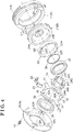
Fig. 4] Fig. 4 is an exploded perspective view of the valve opening and closing timing control apparatus. - An embodiment of the invention is explained with reference to the attached drawings.
- As illustrated in
Figs. 1 to 4 , a valve opening and closingtiming control apparatus 1 is constructed by including a driving-side rotational member A rotating synchronously with acrankshaft 2 of an engine E which serves as an internal combustion engine, a driven-side rotational member B rotating integrally with anintake camshaft 3, and a phase adjustment mechanism C specifying a relative rotational phase between the driving-side rotational member A and the driven-side rotational member B by a driving force of a phase control motor M (an example of an electric actuator). - The engine E is constructed as a four-cycle engine where
pistons 4 housed in plural cylinder bores provided at a cylinder block are connected to thecrankshaft 2 by respective connectingrods 5. A timing belt 6 (which may be a timing chain, for example) is wound over from anoutput pulley 2S of thecrankshaft 2 of the engine E to adrive pulley 11S of the driving-side rotational member A. - Accordingly, the valve opening and closing
timing control apparatus 1 entirely rotates about a rotation axis X in a state where the engine E is operated. The driven-side rotational member B is constructed to be displaceable in the same direction as the rotation direction or an opposite direction relative to the driving-side rotational member A by driving of the phase adjustment mechanism C. - In the valve opening and closing
timing control apparatus 1, driving of the phase control motor M is controlled by a control unit such as an ECU, for example, to thereby specify the relative rotational phase between the driving-side rotational member A and the driven-side rotational member B by the phase adjustment mechanism C. By specifying the relative rotational phase in the aforementioned manner, opening and closing timing of eachintake valve 3B controlled by eachcam portion 3A is achieved. - In the driving-side rotational member A, an
outer case 11 at which thedrive pulley 11S is provided and afront plate 12 are fastened together byplural fastening bolts 13. In an inner space of theouter case 11, the driven-side rotational member B and the phase adjustment mechanism C constructed as a hypotrochoid reduction gear (a specific example of a differential deceleration mechanism) are housed. - The driven-side rotational member B is constituted by a
ring gear 21 at which aninternal teeth portion 21A including a number of internal teeth is formed. The phase adjustment mechanism C is constituted by thering gear 21, aninner gear 22 at which anexternal teeth portion 22A including a number of external teeth is formed, adrive shaft 24 linked to theinner gear 22, and acoupling member 30 serving as a linkage mechanism which brings theinner gear 22 to be linked to the driving-side rotational member A. - As illustrated in
Fig. 2 , thering gear 21 is arranged coaxially with the rotation axis X and theinner gear 22 is arranged coaxially with an eccentric axis Y which is in parallel with the rotation axis X. A part of theexternal teeth portion 22A is meshed with a part of theinternal teeth portion 21A. The number of teeth of theexternal teeth portion 22A of theinner gear 22 is less by one than the number of teeth of theinternal teeth portion 21A of thering gear 21. - The phase control motor M (an electric motor) is supported at the engine E by a
support frame 7 so that an output shaft Ma of the phase control motor M is arranged coaxially with the rotation axis X. - The
ring gear 21 includes a construction where a drivenplate 21P arranged orthogonal to the rotation axis X is integrally provided with a ring-formed portion at which theinternal teeth portion 21A is provided. Aconnection bolt 35 is inserted to be positioned within a bore portion at a center of the drivenplate 21P to be meshed with theintake camshaft 3. As a result, thering gear 21 is connected to theintake camshaft 3 so as to be coaxial with the rotation axis X. - The
drive shaft 24 includes afirst support portion 24A at an outer end side in a direction along the rotation axis X and asecond support portion 24B at an inner end side in the direction along the rotation axis X. Thefirst support portion 24A forms an outer peripheral surface with reference to the rotation axis X and thesecond support portion 24B forms an outer peripheral surface with reference to the eccentric axis Y. A pair of cut portions is formed at the outer periphery of thesecond support portion 24B so thatspring members 25 are fitted in the respective cut portions. Thedrive shaft 24 also includes abore portion 24C with reference to the rotation axis X. A pair ofengagement grooves 24T is formed at thebore portion 24C so as to be parallel with the rotation axis X.Engagement members 28 of the output shaft Ma of the phase control motor M engage with the pair ofengagement grooves 24T. - A
single lubrication groove 24G in parallel with the rotation axis X is formed at thebore portion 24C. Alubrication passage 24R is formed by penetrating through from thelubrication groove 24G to an outer surface and a pair oflubrication passages 24R is formed by penetrating through from the pair ofengagement grooves 24T to the outer surface (seeFig. 3 ). - As illustrated in
Fig. 1 , afirst ball bearing 26 is fitted in an opening at a center of thefront plate 12. Thefirst support portion 24A is inserted to be positioned within thefirst ball bearing 26 so that thedrive shaft 24 is rotatably supported relative to the driving-side rotational member A with reference to the rotation axis X. - In addition, a second ball bearing 27 is externally fitted to the
second support portion 24B of thedrive shaft 24 and is fitted in the pair of cut portions of thedrive shaft 24 so that a biasing force is applied to an inner circumference of thesecond ball bearing 27. Theinner gear 22 is externally fitted to the second ball bearing 27 so as to be rotatable. Further, a C-ring 29 serving as a retaining ring is provided to inhibit the second ball bearing 27 from disengaging from thesecond support portion 24B. - Accordingly, the part of the
external teeth portion 22A of theinner gear 22 is meshed with the part of theinternal teeth portion 21A of thering gear 21 while theinner gear 22 is supported to be rotatable with reference to the eccentric axis Y. The aforementioned meshing is held by the biasing force of the pair ofspring members 25. - The
coupling member 30 constituting the linkage mechanism is manufactured by press working on a plate-formed member. Thecoupling member 30 integrally includes a pair of first engagement arms 31 (each of which serves as an example of a first engagement portion) protruding outwardly with reference to the rotation axis X, a pair of second engagement arms 32 (each of which serves as an example of a second engagement portion) protruding in a direction orthogonal to thefirst engagement arms 31, and a ring-formedportion 33 connecting thefirst engagement arms 31 and thesecond engagement arms 32.Engagement recess portions 32A are formed at the respective second engagement arms 32 (the example of the second engagement portion) so as to open towards the rotation axis X. - The pair of
first engagement arms 31, the pair ofsecond engagement arms 32 and the ring-formedportion 33 connecting thefirst engagement arms 31 and thesecond engagement arms 32 are arranged on an imaginary plane orthogonal to the rotation axis X. - Each of the first engagement arms 31 (the example of the first engagement portion) is constituted in a plate-formed region which linearly extends along a first direction as viewed in the direction along the rotation axis X. Each of the
engagement recess portions 32A of the second engagement arms 32 (the example of the second engagement portion) is formed in a recess form recessed along a second direction as viewed in the direction along the rotation axis X. - A pair of first linkage portions AT (each of which serves as a specific example of a penetration groove) is formed as a penetration groove at a connection surface of the
outer case 11 constituting the driving-side rotational member A, the connection surface making contact with thefront plate 12. Each of the first linkage portions AT extends in a radial direction with reference to the rotation axis X from the inner space to an outer space of theouter case 11. A direction of a straight line where the pair of first linkage portions AT is arranged side by side corresponds to the first direction (i.e., a left-right direction inFig. 3 ). A pair ofsecond linkage portions 22T is formed as protrusions at positions in an end surface of theinner gear 22, the positions being opposed to each other with reference to the eccentric axis Y. A direction where the pair ofsecond linkage portions 22T is arranged side by side corresponds to the second direction (i.e., an up-down direction inFig. 3 ). - As illustrated in
Fig. 3 , each of the first linkage portions AT includes a pair of first guide surfaces G1 formed in parallel with the first direction as viewed in the direction along the rotation axis X. Each of thesecond linkage portions 22T is formed in a rectangular form while including a pair of second guide surfaces G2 formed in parallel with the second direction as viewed in the direction along the rotation axis X. - In the aforementioned construction, the
first engagement arms 31 of thecoupling member 30 are brought to engage with the first linkage portions AT while theengagement recess portions 32A of thesecond engagement arms 32 of thecoupling member 30 are brought to engage with thesecond linkage portions 22T so that thecoupling member 30 may function as an Oldham coupling. - Based on the aforementioned engagement, a positional relationship where linear portions of the
first engagement arm 31 make contact with the first guide surfaces G1 of the first linkage portion AT and linear portions in the recess portion of thesecond engagement arm 32 make contact with the second guide surfaces G2 of thesecond linkage portion 22T is obtained. - As illustrated in
Fig. 4 , a groove depth L1 of the first linkage portion AT is specified sufficiently greater than a thickness L2 of thefirst engagement arm 31. Thus, a front surface of thefirst engagement arm 31 makes contact with thefront plate 12 while a clearance is defined between a rear surface of thefirst engagement arm 31 and a bottom portion of the first linkage portion AT. - Plural projecting
portions 12A are provided at an inner surface of thefront plate 12 so as to position thering gear 21 in the direction along the rotation axis X by making contact with an end surface of thering gear 21. - The output shaft Ma of the phase control motor M is driven to rotate at a faster speed or a slower speed than the rotation speed of the
intake camshaft 3 so as to bring the eccentric axis Y of thesecond support portion 24B to revolve about the rotation axis X. Because of the aforementioned revolution, meshing position of theinternal teeth portion 21A of thering gear 21 with theexternal teeth portion 22A of theinner gear 22 moves along an inner circumference of thering gear 21, so that theinner gear 22 may rotate with reference to the eccentric axis Y. - In a case where the eccentric axis Y of the
inner gear 22 revolves about the rotation axis X, displacement of theinner gear 22 is transmitted to theengagement recess portions 32A from thesecond linkage portions 22T. In a case where the displacement includes a component in the first direction, thecoupling member 30 is displaced in the first direction with the displacement of theinner gear 22. In a case where the displacement includes a component in the second direction, thecoupling member 30 is inhibited from being displaced and theinner gear 22 only is displaced in the second direction. It is understandable that thecoupling member 30 may be displaced simultaneously in the first direction and the second direction. - The number of teeth of the
external teeth portion 22A of theinner gear 22 is specified less by one than the number of teeth of theinternal teeth portion 21A of thering gear 21. Thus, in a case of one revolution of the eccentric axis Y of theinner gear 22 about the rotation axis X, thering gear 21 rotates by one tooth, which realizes a large deceleration. - In the aforementioned construction, the relative rotation between the
inner gear 22 and theouter case 11 which constitutes the driving-side rotational member A is restricted by thecoupling member 30. Thus, thering gear 21 rotates with reference to the rotation axis X by a rotation force applied in a direction where theinner gear 22 rotates with the revolution of theinner gear 22. That is, by the revolution of theinner gear 22 relative to thering gear 21, thering gear 21 rotates with reference to the driving-side rotational member A. As a result, the relative rotational phase between the driving-side rotational member A and the driven-side rotational member B are specified to achieve setting of the opening and closing timing by theintake camshaft 3. - According to the aforementioned construction, in a case where the eccentric axis Y of the
inner gear 22 revolves relative to thering gear 21, thecoupling member 30 is displaced in the first direction and the second direction. Thus, the relative rotation between theinner gear 22 and the driving-side rotational member A is interfered and theintake camshaft 3 connected to the ring gear 21 (driven-side rotational member B) is rotated relative to the driving-side rotational member A. In addition, because thecoupling member 30 which may be formed thinner by press working on the plate-formed member is provided, the thickness of the valve opening and closingtiming control apparatus 1 may be reduced. - For example, in a case where the
coupling member 30 is displaced in the first direction, each of thefirst engagement arms 31 is guided by the first guide surfaces G1 of the first linkage portion AT in a state of slidably contacting the first guide surfaces G1. In a case where thecoupling member 30 is displaced in the second direction, theengagement recess portion 32A of each of thesecond engagement arms 32 is guided by the second guide surfaces G2 of thesecond linkage portion 22T in a state of slidably contacting with the second guide surfaces G2. Because of the aforementioned guiding, smooth linear displacement is performed at each sliding portion so that the sliding portion is inhibited from locally receiving stress. - The valve opening and closing
timing control apparatus 1 is arranged at an inner portion of a chain case that drives theintake camshaft 3 and an exhaust camshaft of the engine E. Because of such positional relationship, a part of lubricant supplied to the camshaft or a chain flows into thebore portion 24C of thedrive shaft 24 from the opening at the center of thefront plate 12 and is supplied to each portion in the inner space of theouter case 11, thereby smoothly operating the phase adjustment mechanism C. - That is, the lubricant flowing into the
bore portion 24C is supplied to an inner portion of thering gear 21 from an inner end position and is supplied between theinternal teeth portion 21A of thering gear 21 and theexternal teeth portion 22A of theinner gear 22 to thereafter flow to the inner space of theouter case 11. A part of the lubricant flowing to thebore portion 24C flows to an outer surface of thedrive shaft 24 from theplural lubrication grooves 24G so as to be supplied to between thefirst engagement arms 31 of thecoupling member 30 and the first linkage portions AT and between thesecond engagement arms 32 and thesecond linkage portions 22T. - Specifically, because the valve opening and closing
timing control apparatus 1 rotates, the lubricant at the inner space of theouter case 11 and the lubricant supplied to thefirst engagement arms 31 are discharged to the outside by inertia force through a clearance between each of the first linkage portions AT and thefirst engagement arms 31. Because the lubricant is discharged to the outside through the clearance, dust and dirt at the inner space may be discharged together with the lubricant, for example. - In addition, because the plural projecting
portions 12A provided at the inner surface of thefront plate 12 are arranged contactable with the end surface of thering gear 21, the position of thering gear 21 in the direction along the rotation axis X is determined. - The present invention may be constructed as below, in addition to the aforementioned embodiment (components including the same functions as the embodiment bear the same reference numerals as the embodiment).
- (a) The first linkage portions AT which engage with the respective
first engagement arms 31 may be provided at thefront plate 12. In addition, grooves may be formed at opposed surfaces of theouter case 11 and thefront plate 12 along the first direction to constitute the first linkage portions AT. - (b) Even in a case where the first linkage portions AT are formed at any of the
outer case 11 and thefront plate 12, the construction where the first linkage portion AT extends through from the inner space to the outer space of theouter case 11 is not necessarily employed. The first linkage portion AT may be a sac hole not being communicated to the outer space. - (c) The first linkage portion AT may be constructed so that a recess portion in a groove formed at the
first engagement arm 31 may be fitted to a guide member provided in a projecting form at theouter case 11 so as to be movable relative to the guide member. - (d) The
second linkage portion 22T may be constructed so that a groove portion which radially extends is formed at the end surface of theinner gear 22 and a member that is fitted in the groove portion may be provided at thecoupling member 30. - The present invention is applicable to a valve opening and closing timing control apparatus including a phase adjustment mechanism where external teeth of an inner gear are meshed with internal teeth of a ring gear.
-
- 1
- valve opening and closing timing control apparatus
- 2
- crank shaft
- 3
- camshaft (intake camshaft)
- 11
- outer case
- 12
- plate (front plate)
- 12A
- projecting portion
- 21
- ring gear
- 21A
- teeth portion (internal teeth portion)
- 22
- inner gear
- 22A
- teeth portion (external teeth portion)
- 30
- linkage mechanism, coupling member
- 31
- first engagement portion (first engagement arm)
- 32
- second engagement portion (second engagement arm)
- A
- driving-side rotational member
- AT
- penetration groove
- B
- driven-side rotational member
- C
- phase adjustment mechanism
- E
- internal combustion engine (engine)
- M
- electric actuator (phase control motor)
- X
- rotation axis
- Y
- eccentric axis
Claims (4)
- A valve opening and closing timing control apparatus comprising:a driving-side rotational member rotating synchronously with a crankshaft of an internal combustion engine about a rotation axis of the driving-side rotational member;a driven-side rotational member arranged coaxially with the rotation axis of the driving-side rotational member and rotatable relative to the driving-side rotational member, the driven-side rotational member rotating integrally with a camshaft for opening and closing a valve of the internal combustion engine; anda phase adjustment mechanism specifying a relative rotational phase between the driving-side rotational member and the driven-side rotational member by an electric actuator,the phase adjustment mechanism including a ring gear arranged coaxially with the rotation axis, the ring gear including internal teeth and serving as the driven-side rotational member, an inner gear arranged coaxially with an eccentric axis which is in parallel with the rotation axis, the inner gear including external teeth of which number is different from a number of teeth of the ring gear, and a linkage mechanism which brings the inner gear to be linked to the driving-side rotational member, the phase adjustment mechanism being constructed as a differential deceleration mechanism where the inner gear is rotated relative to the ring gear by revolution of a position of the eccentric axis with reference to the rotation axis by a driving force of the electric actuator in a state where a part of a teeth portion of the ring gear is meshed with a part of a teeth portion of the inner gear,the linkage mechanism being constructed by including a coupling member at which a first engagement portion engaging with the driving-side rotational member in a displaceable manner in a first direction serving as a radial direction and a second engagement portion engaging with the inner gear in a displaceable manner in a second direction orthogonal to the first direction are integrally provided on an imaginary plane orthogonal to the rotation axis.
- The valve opening and closing timing control apparatus according to claim 1, wherein the linkage mechanism is constructed by including a penetration groove which penetrates through from an inner space to an outer space of the driving-side rotational member along the first direction and the coupling member including the first engagement portion formed in an arm form for engagement with the penetration groove.
- The valve opening and closing timing control apparatus according to claim 2, wherein the driving-side rotational member is constituted by an outer case including an inner space which houses the phase adjustment mechanism and a plate covering the outer case, the penetration groove being provided at the outer case.
- The valve opening and closing timing control apparatus according to claim 3, wherein the plate includes a projecting portion at an inner surface for positioning the ring gear in a direction along the rotation axis by making contact with the ring gear.
Applications Claiming Priority (2)
| Application Number | Priority Date | Filing Date | Title |
|---|---|---|---|
| JP2015249014A JP6531641B2 (en) | 2015-12-21 | 2015-12-21 | Valve timing control device |
| PCT/JP2016/077523 WO2017110172A1 (en) | 2015-12-21 | 2016-09-16 | Valve opening/closing timing control device |
Publications (3)
| Publication Number | Publication Date |
|---|---|
| EP3396124A1 true EP3396124A1 (en) | 2018-10-31 |
| EP3396124A4 EP3396124A4 (en) | 2019-01-09 |
| EP3396124B1 EP3396124B1 (en) | 2019-10-23 |
Family
ID=59089975
Family Applications (1)
| Application Number | Title | Priority Date | Filing Date |
|---|---|---|---|
| EP16878069.0A Active EP3396124B1 (en) | 2015-12-21 | 2016-09-16 | Valve opening/closing timing control device |
Country Status (5)
| Country | Link |
|---|---|
| US (1) | US10450906B2 (en) |
| EP (1) | EP3396124B1 (en) |
| JP (1) | JP6531641B2 (en) |
| CN (1) | CN208364192U (en) |
| WO (1) | WO2017110172A1 (en) |
Cited By (1)
| Publication number | Priority date | Publication date | Assignee | Title |
|---|---|---|---|---|
| DE102018125582B4 (en) | 2017-11-06 | 2023-09-28 | Denso Corporation | Valve timing adjustment device |
Families Citing this family (14)
| Publication number | Priority date | Publication date | Assignee | Title |
|---|---|---|---|---|
| JP2018096387A (en) * | 2016-12-08 | 2018-06-21 | アイシン精機株式会社 | Gear transmission mechanism |
| JP6965636B2 (en) * | 2017-08-30 | 2021-11-10 | 株式会社デンソー | Valve timing adjuster |
| JP7006023B2 (en) * | 2017-08-30 | 2022-01-24 | 株式会社デンソー | Eccentric swing type speed reducer |
| JP2019157679A (en) * | 2018-03-08 | 2019-09-19 | アイシン精機株式会社 | Valve opening/closing timing controller |
| CN108798819B (en) * | 2018-06-22 | 2023-11-21 | 绵阳富临精工机械股份有限公司 | Electric phase adjusting device |
| CN108952873B (en) * | 2018-08-31 | 2023-11-03 | 绵阳富临精工机械股份有限公司 | Rear-mounted VVT phaser |
| CN108979775B (en) * | 2018-08-31 | 2023-10-31 | 绵阳富临精工机械股份有限公司 | Front-mounted VVT (variable valve timing) phaser |
| JP7206712B2 (en) * | 2018-09-05 | 2023-01-18 | 株式会社アイシン | Valve timing control device |
| JP7243252B2 (en) | 2019-02-12 | 2023-03-22 | 株式会社デンソー | VALVE TIMING ADJUSTMENT DEVICE, CONTROL DEVICE AND CONTROL METHOD THEREOF |
| JP7226780B2 (en) * | 2019-03-15 | 2023-02-21 | 株式会社Soken | valve timing adjuster |
| JP7226779B2 (en) * | 2019-03-15 | 2023-02-21 | 株式会社Soken | valve timing adjuster |
| JP7400236B2 (en) * | 2019-07-18 | 2023-12-19 | 株式会社アイシン | Valve opening/closing timing control device |
| JP7338289B2 (en) * | 2019-07-18 | 2023-09-05 | 株式会社アイシン | Valve timing control device |
| CN116122931A (en) * | 2023-02-13 | 2023-05-16 | 富临精工股份有限公司 | Cam shaft phase modulator |
Family Cites Families (19)
| Publication number | Priority date | Publication date | Assignee | Title |
|---|---|---|---|---|
| JPS4950641U (en) * | 1972-08-14 | 1974-05-04 | ||
| JPS62101943A (en) * | 1985-10-30 | 1987-05-12 | Hitachi Ltd | reduction gear |
| DE59802310D1 (en) * | 1997-09-19 | 2002-01-17 | Tcg Unitech Ag | Device for adjusting the camshaft of an internal combustion engine |
| JP3937164B2 (en) | 2002-04-19 | 2007-06-27 | 株式会社デンソー | Valve timing adjustment device |
| DE10248355A1 (en) * | 2002-10-17 | 2004-04-29 | Ina-Schaeffler Kg | Camshaft adjuster with electric drive |
| JP4269341B2 (en) * | 2004-04-23 | 2009-05-27 | 株式会社デンソー | Valve timing adjustment device |
| DE102005018956A1 (en) | 2005-04-23 | 2006-11-23 | Schaeffler Kg | Device for adjusting the camshaft of an internal combustion engine |
| JP2007071060A (en) * | 2005-09-05 | 2007-03-22 | Denso Corp | Valve timing adjustment device |
| JP4924922B2 (en) * | 2006-01-16 | 2012-04-25 | 株式会社デンソー | Valve timing adjustment device |
| KR20110074753A (en) * | 2008-10-22 | 2011-07-01 | 니탄 밸브 가부시키가이샤 | Phase-variable device in automobile engine |
| JP4987031B2 (en) * | 2009-04-27 | 2012-07-25 | 日立オートモティブシステムズ株式会社 | Valve timing control device for internal combustion engine |
| JP5538053B2 (en) * | 2010-04-28 | 2014-07-02 | 日立オートモティブシステムズ株式会社 | Variable valve operating device for internal combustion engine |
| JP5666922B2 (en) * | 2011-01-12 | 2015-02-12 | 日立オートモティブシステムズ株式会社 | Valve timing controller and internal combustion engine valve timing controller |
| DE102012013660A1 (en) * | 2012-07-10 | 2014-01-30 | Iwis Motorsysteme Gmbh & Co. Kg | Chain-based transmission device |
| CN104379885B (en) * | 2012-07-12 | 2016-12-07 | 日立汽车系统株式会社 | The variable valve gear of internal combustion engine |
| WO2014016242A1 (en) * | 2012-07-25 | 2014-01-30 | Hilite Germany Gmbh | Camshaft adjuster transmission |
| DE102013215816B3 (en) * | 2013-04-22 | 2014-10-16 | Magna Powertrain Ag & Co. Kg | Phaser |
| JP2015102064A (en) * | 2013-11-27 | 2015-06-04 | アイシン精機株式会社 | Valve timing control device |
| JP5987868B2 (en) * | 2014-07-22 | 2016-09-07 | 株式会社デンソー | Valve timing adjustment device |
-
2015
- 2015-12-21 JP JP2015249014A patent/JP6531641B2/en active Active
-
2016
- 2016-09-16 WO PCT/JP2016/077523 patent/WO2017110172A1/en not_active Ceased
- 2016-09-16 US US15/769,186 patent/US10450906B2/en active Active
- 2016-09-16 EP EP16878069.0A patent/EP3396124B1/en active Active
- 2016-09-16 CN CN201690001305.7U patent/CN208364192U/en active Active
Cited By (1)
| Publication number | Priority date | Publication date | Assignee | Title |
|---|---|---|---|---|
| DE102018125582B4 (en) | 2017-11-06 | 2023-09-28 | Denso Corporation | Valve timing adjustment device |
Also Published As
| Publication number | Publication date |
|---|---|
| US10450906B2 (en) | 2019-10-22 |
| WO2017110172A1 (en) | 2017-06-29 |
| JP6531641B2 (en) | 2019-06-19 |
| CN208364192U (en) | 2019-01-11 |
| US20180306070A1 (en) | 2018-10-25 |
| EP3396124B1 (en) | 2019-10-23 |
| EP3396124A4 (en) | 2019-01-09 |
| JP2017115601A (en) | 2017-06-29 |
Similar Documents
| Publication | Publication Date | Title |
|---|---|---|
| EP3396124B1 (en) | Valve opening/closing timing control device | |
| CN110023596B (en) | Valve timing control device | |
| CN107829792B (en) | Valve timing control device | |
| CN107829793B (en) | Valve timing control device | |
| US10731521B2 (en) | Valve opening and closing timing control apparatus | |
| JPH11218014A (en) | Variable valve timing device | |
| EP2613029A1 (en) | Camshaft device | |
| JP6604188B2 (en) | Valve timing control device | |
| WO2018092390A1 (en) | Valve opening/closing timing control device | |
| CN110878716B (en) | Valve timing control device | |
| CN112585338B (en) | Phase changing unit and valve timing changing device | |
| JP2015045282A (en) | Valve opening/closing timing control device | |
| CN213360202U (en) | Valve timing control device | |
| EP3936739B1 (en) | Electric actuator | |
| JP2023086586A (en) | Valve timing control device | |
| JP4447564B2 (en) | Valve timing adjustment device | |
| JP7040283B2 (en) | Valve opening / closing timing control device | |
| US20260028922A1 (en) | Valve open and close period control device | |
| JP2024119301A (en) | Valve timing adjustment device | |
| JPH07139318A (en) | Valve timing adjustment device | |
| CN116255218A (en) | valve timing control device | |
| JP2003120225A (en) | Valve timing control device for internal combustion engine | |
| JP2019044617A (en) | Valve timing adjustment device | |
| JP2000356114A (en) | Valve timing adjustment device |
Legal Events
| Date | Code | Title | Description |
|---|---|---|---|
| STAA | Information on the status of an ep patent application or granted ep patent |
Free format text: STATUS: THE INTERNATIONAL PUBLICATION HAS BEEN MADE |
|
| PUAI | Public reference made under article 153(3) epc to a published international application that has entered the european phase |
Free format text: ORIGINAL CODE: 0009012 |
|
| STAA | Information on the status of an ep patent application or granted ep patent |
Free format text: STATUS: REQUEST FOR EXAMINATION WAS MADE |
|
| 17P | Request for examination filed |
Effective date: 20180406 |
|
| AK | Designated contracting states |
Kind code of ref document: A1 Designated state(s): AL AT BE BG CH CY CZ DE DK EE ES FI FR GB GR HR HU IE IS IT LI LT LU LV MC MK MT NL NO PL PT RO RS SE SI SK SM TR |
|
| AX | Request for extension of the european patent |
Extension state: BA ME |
|
| REG | Reference to a national code |
Ref country code: DE Ref legal event code: R079 Ref document number: 602016023140 Country of ref document: DE Free format text: PREVIOUS MAIN CLASS: F01L0001344000 Ipc: F01L0001352000 |
|
| A4 | Supplementary search report drawn up and despatched |
Effective date: 20181211 |
|
| RIC1 | Information provided on ipc code assigned before grant |
Ipc: F01L 1/352 20060101AFI20181205BHEP |
|
| DAV | Request for validation of the european patent (deleted) | ||
| DAX | Request for extension of the european patent (deleted) | ||
| GRAP | Despatch of communication of intention to grant a patent |
Free format text: ORIGINAL CODE: EPIDOSNIGR1 |
|
| STAA | Information on the status of an ep patent application or granted ep patent |
Free format text: STATUS: GRANT OF PATENT IS INTENDED |
|
| INTG | Intention to grant announced |
Effective date: 20190607 |
|
| GRAS | Grant fee paid |
Free format text: ORIGINAL CODE: EPIDOSNIGR3 |
|
| GRAA | (expected) grant |
Free format text: ORIGINAL CODE: 0009210 |
|
| STAA | Information on the status of an ep patent application or granted ep patent |
Free format text: STATUS: THE PATENT HAS BEEN GRANTED |
|
| AK | Designated contracting states |
Kind code of ref document: B1 Designated state(s): AL AT BE BG CH CY CZ DE DK EE ES FI FR GB GR HR HU IE IS IT LI LT LU LV MC MK MT NL NO PL PT RO RS SE SI SK SM TR |
|
| REG | Reference to a national code |
Ref country code: GB Ref legal event code: FG4D |
|
| REG | Reference to a national code |
Ref country code: CH Ref legal event code: EP |
|
| REG | Reference to a national code |
Ref country code: IE Ref legal event code: FG4D |
|
| REG | Reference to a national code |
Ref country code: DE Ref legal event code: R096 Ref document number: 602016023140 Country of ref document: DE |
|
| REG | Reference to a national code |
Ref country code: AT Ref legal event code: REF Ref document number: 1193869 Country of ref document: AT Kind code of ref document: T Effective date: 20191115 |
|
| REG | Reference to a national code |
Ref country code: NL Ref legal event code: MP Effective date: 20191023 |
|
| REG | Reference to a national code |
Ref country code: LT Ref legal event code: MG4D |
|
| PG25 | Lapsed in a contracting state [announced via postgrant information from national office to epo] |
Ref country code: BG Free format text: LAPSE BECAUSE OF FAILURE TO SUBMIT A TRANSLATION OF THE DESCRIPTION OR TO PAY THE FEE WITHIN THE PRESCRIBED TIME-LIMIT Effective date: 20200123 Ref country code: FI Free format text: LAPSE BECAUSE OF FAILURE TO SUBMIT A TRANSLATION OF THE DESCRIPTION OR TO PAY THE FEE WITHIN THE PRESCRIBED TIME-LIMIT Effective date: 20191023 Ref country code: PT Free format text: LAPSE BECAUSE OF FAILURE TO SUBMIT A TRANSLATION OF THE DESCRIPTION OR TO PAY THE FEE WITHIN THE PRESCRIBED TIME-LIMIT Effective date: 20200224 Ref country code: NL Free format text: LAPSE BECAUSE OF FAILURE TO SUBMIT A TRANSLATION OF THE DESCRIPTION OR TO PAY THE FEE WITHIN THE PRESCRIBED TIME-LIMIT Effective date: 20191023 Ref country code: PL Free format text: LAPSE BECAUSE OF FAILURE TO SUBMIT A TRANSLATION OF THE DESCRIPTION OR TO PAY THE FEE WITHIN THE PRESCRIBED TIME-LIMIT Effective date: 20191023 Ref country code: LV Free format text: LAPSE BECAUSE OF FAILURE TO SUBMIT A TRANSLATION OF THE DESCRIPTION OR TO PAY THE FEE WITHIN THE PRESCRIBED TIME-LIMIT Effective date: 20191023 Ref country code: NO Free format text: LAPSE BECAUSE OF FAILURE TO SUBMIT A TRANSLATION OF THE DESCRIPTION OR TO PAY THE FEE WITHIN THE PRESCRIBED TIME-LIMIT Effective date: 20200123 Ref country code: SE Free format text: LAPSE BECAUSE OF FAILURE TO SUBMIT A TRANSLATION OF THE DESCRIPTION OR TO PAY THE FEE WITHIN THE PRESCRIBED TIME-LIMIT Effective date: 20191023 Ref country code: GR Free format text: LAPSE BECAUSE OF FAILURE TO SUBMIT A TRANSLATION OF THE DESCRIPTION OR TO PAY THE FEE WITHIN THE PRESCRIBED TIME-LIMIT Effective date: 20200124 Ref country code: LT Free format text: LAPSE BECAUSE OF FAILURE TO SUBMIT A TRANSLATION OF THE DESCRIPTION OR TO PAY THE FEE WITHIN THE PRESCRIBED TIME-LIMIT Effective date: 20191023 |
|
| PG25 | Lapsed in a contracting state [announced via postgrant information from national office to epo] |
Ref country code: HR Free format text: LAPSE BECAUSE OF FAILURE TO SUBMIT A TRANSLATION OF THE DESCRIPTION OR TO PAY THE FEE WITHIN THE PRESCRIBED TIME-LIMIT Effective date: 20191023 Ref country code: IS Free format text: LAPSE BECAUSE OF FAILURE TO SUBMIT A TRANSLATION OF THE DESCRIPTION OR TO PAY THE FEE WITHIN THE PRESCRIBED TIME-LIMIT Effective date: 20200224 Ref country code: RS Free format text: LAPSE BECAUSE OF FAILURE TO SUBMIT A TRANSLATION OF THE DESCRIPTION OR TO PAY THE FEE WITHIN THE PRESCRIBED TIME-LIMIT Effective date: 20191023 |
|
| PG25 | Lapsed in a contracting state [announced via postgrant information from national office to epo] |
Ref country code: AL Free format text: LAPSE BECAUSE OF FAILURE TO SUBMIT A TRANSLATION OF THE DESCRIPTION OR TO PAY THE FEE WITHIN THE PRESCRIBED TIME-LIMIT Effective date: 20191023 |
|
| REG | Reference to a national code |
Ref country code: DE Ref legal event code: R097 Ref document number: 602016023140 Country of ref document: DE |
|
| PG2D | Information on lapse in contracting state deleted |
Ref country code: IS |
|
| PG25 | Lapsed in a contracting state [announced via postgrant information from national office to epo] |
Ref country code: EE Free format text: LAPSE BECAUSE OF FAILURE TO SUBMIT A TRANSLATION OF THE DESCRIPTION OR TO PAY THE FEE WITHIN THE PRESCRIBED TIME-LIMIT Effective date: 20191023 Ref country code: DK Free format text: LAPSE BECAUSE OF FAILURE TO SUBMIT A TRANSLATION OF THE DESCRIPTION OR TO PAY THE FEE WITHIN THE PRESCRIBED TIME-LIMIT Effective date: 20191023 Ref country code: ES Free format text: LAPSE BECAUSE OF FAILURE TO SUBMIT A TRANSLATION OF THE DESCRIPTION OR TO PAY THE FEE WITHIN THE PRESCRIBED TIME-LIMIT Effective date: 20191023 Ref country code: RO Free format text: LAPSE BECAUSE OF FAILURE TO SUBMIT A TRANSLATION OF THE DESCRIPTION OR TO PAY THE FEE WITHIN THE PRESCRIBED TIME-LIMIT Effective date: 20191023 Ref country code: CZ Free format text: LAPSE BECAUSE OF FAILURE TO SUBMIT A TRANSLATION OF THE DESCRIPTION OR TO PAY THE FEE WITHIN THE PRESCRIBED TIME-LIMIT Effective date: 20191023 Ref country code: IS Free format text: LAPSE BECAUSE OF FAILURE TO SUBMIT A TRANSLATION OF THE DESCRIPTION OR TO PAY THE FEE WITHIN THE PRESCRIBED TIME-LIMIT Effective date: 20200223 |
|
| REG | Reference to a national code |
Ref country code: AT Ref legal event code: MK05 Ref document number: 1193869 Country of ref document: AT Kind code of ref document: T Effective date: 20191023 |
|
| PLBE | No opposition filed within time limit |
Free format text: ORIGINAL CODE: 0009261 |
|
| STAA | Information on the status of an ep patent application or granted ep patent |
Free format text: STATUS: NO OPPOSITION FILED WITHIN TIME LIMIT |
|
| PG25 | Lapsed in a contracting state [announced via postgrant information from national office to epo] |
Ref country code: SM Free format text: LAPSE BECAUSE OF FAILURE TO SUBMIT A TRANSLATION OF THE DESCRIPTION OR TO PAY THE FEE WITHIN THE PRESCRIBED TIME-LIMIT Effective date: 20191023 Ref country code: IT Free format text: LAPSE BECAUSE OF FAILURE TO SUBMIT A TRANSLATION OF THE DESCRIPTION OR TO PAY THE FEE WITHIN THE PRESCRIBED TIME-LIMIT Effective date: 20191023 Ref country code: SK Free format text: LAPSE BECAUSE OF FAILURE TO SUBMIT A TRANSLATION OF THE DESCRIPTION OR TO PAY THE FEE WITHIN THE PRESCRIBED TIME-LIMIT Effective date: 20191023 |
|
| 26N | No opposition filed |
Effective date: 20200724 |
|
| PG25 | Lapsed in a contracting state [announced via postgrant information from national office to epo] |
Ref country code: SI Free format text: LAPSE BECAUSE OF FAILURE TO SUBMIT A TRANSLATION OF THE DESCRIPTION OR TO PAY THE FEE WITHIN THE PRESCRIBED TIME-LIMIT Effective date: 20191023 Ref country code: AT Free format text: LAPSE BECAUSE OF FAILURE TO SUBMIT A TRANSLATION OF THE DESCRIPTION OR TO PAY THE FEE WITHIN THE PRESCRIBED TIME-LIMIT Effective date: 20191023 |
|
| REG | Reference to a national code |
Ref country code: CH Ref legal event code: PL |
|
| GBPC | Gb: european patent ceased through non-payment of renewal fee |
Effective date: 20200916 |
|
| REG | Reference to a national code |
Ref country code: BE Ref legal event code: MM Effective date: 20200930 |
|
| PG25 | Lapsed in a contracting state [announced via postgrant information from national office to epo] |
Ref country code: LU Free format text: LAPSE BECAUSE OF NON-PAYMENT OF DUE FEES Effective date: 20200916 |
|
| PG25 | Lapsed in a contracting state [announced via postgrant information from national office to epo] |
Ref country code: BE Free format text: LAPSE BECAUSE OF NON-PAYMENT OF DUE FEES Effective date: 20200930 Ref country code: CH Free format text: LAPSE BECAUSE OF NON-PAYMENT OF DUE FEES Effective date: 20200930 Ref country code: LI Free format text: LAPSE BECAUSE OF NON-PAYMENT OF DUE FEES Effective date: 20200930 Ref country code: IE Free format text: LAPSE BECAUSE OF NON-PAYMENT OF DUE FEES Effective date: 20200916 Ref country code: GB Free format text: LAPSE BECAUSE OF NON-PAYMENT OF DUE FEES Effective date: 20200916 |
|
| PG25 | Lapsed in a contracting state [announced via postgrant information from national office to epo] |
Ref country code: TR Free format text: LAPSE BECAUSE OF FAILURE TO SUBMIT A TRANSLATION OF THE DESCRIPTION OR TO PAY THE FEE WITHIN THE PRESCRIBED TIME-LIMIT Effective date: 20191023 Ref country code: MT Free format text: LAPSE BECAUSE OF FAILURE TO SUBMIT A TRANSLATION OF THE DESCRIPTION OR TO PAY THE FEE WITHIN THE PRESCRIBED TIME-LIMIT Effective date: 20191023 Ref country code: CY Free format text: LAPSE BECAUSE OF FAILURE TO SUBMIT A TRANSLATION OF THE DESCRIPTION OR TO PAY THE FEE WITHIN THE PRESCRIBED TIME-LIMIT Effective date: 20191023 |
|
| PG25 | Lapsed in a contracting state [announced via postgrant information from national office to epo] |
Ref country code: MK Free format text: LAPSE BECAUSE OF FAILURE TO SUBMIT A TRANSLATION OF THE DESCRIPTION OR TO PAY THE FEE WITHIN THE PRESCRIBED TIME-LIMIT Effective date: 20191023 Ref country code: MC Free format text: LAPSE BECAUSE OF FAILURE TO SUBMIT A TRANSLATION OF THE DESCRIPTION OR TO PAY THE FEE WITHIN THE PRESCRIBED TIME-LIMIT Effective date: 20191023 |
|
| PGFP | Annual fee paid to national office [announced via postgrant information from national office to epo] |
Ref country code: DE Payment date: 20250730 Year of fee payment: 10 |
|
| PGFP | Annual fee paid to national office [announced via postgrant information from national office to epo] |
Ref country code: FR Payment date: 20250808 Year of fee payment: 10 |