EP3396060A1 - Processing device, sheet manufacturing apparatus, processing method, and sheet manufacturing method - Google Patents
Processing device, sheet manufacturing apparatus, processing method, and sheet manufacturing method Download PDFInfo
- Publication number
- EP3396060A1 EP3396060A1 EP18168809.4A EP18168809A EP3396060A1 EP 3396060 A1 EP3396060 A1 EP 3396060A1 EP 18168809 A EP18168809 A EP 18168809A EP 3396060 A1 EP3396060 A1 EP 3396060A1
- Authority
- EP
- European Patent Office
- Prior art keywords
- color material
- particles
- processing device
- substrate
- conduit
- Prior art date
- Legal status (The legal status is an assumption and is not a legal conclusion. Google has not performed a legal analysis and makes no representation as to the accuracy of the status listed.)
- Granted
Links
Images




Classifications
-
- D—TEXTILES; PAPER
- D21—PAPER-MAKING; PRODUCTION OF CELLULOSE
- D21B—FIBROUS RAW MATERIALS OR THEIR MECHANICAL TREATMENT
- D21B1/00—Fibrous raw materials or their mechanical treatment
- D21B1/04—Fibrous raw materials or their mechanical treatment by dividing raw materials into small particles, e.g. fibres
- D21B1/12—Fibrous raw materials or their mechanical treatment by dividing raw materials into small particles, e.g. fibres by wet methods, by the use of steam
- D21B1/30—Defibrating by other means
- D21B1/32—Defibrating by other means of waste paper
- D21B1/325—Defibrating by other means of waste paper de-inking devices
-
- D—TEXTILES; PAPER
- D21—PAPER-MAKING; PRODUCTION OF CELLULOSE
- D21B—FIBROUS RAW MATERIALS OR THEIR MECHANICAL TREATMENT
- D21B1/00—Fibrous raw materials or their mechanical treatment
- D21B1/02—Pretreatment of the raw materials by chemical or physical means
-
- D—TEXTILES; PAPER
- D21—PAPER-MAKING; PRODUCTION OF CELLULOSE
- D21C—PRODUCTION OF CELLULOSE BY REMOVING NON-CELLULOSE SUBSTANCES FROM CELLULOSE-CONTAINING MATERIALS; REGENERATION OF PULPING LIQUORS; APPARATUS THEREFOR
- D21C5/00—Other processes for obtaining cellulose, e.g. cooking cotton linters ; Processes characterised by the choice of cellulose-containing starting materials
- D21C5/02—Working-up waste paper
- D21C5/025—De-inking
- D21C5/027—Chemicals therefor
-
- D—TEXTILES; PAPER
- D21—PAPER-MAKING; PRODUCTION OF CELLULOSE
- D21H—PULP COMPOSITIONS; PREPARATION THEREOF NOT COVERED BY SUBCLASSES D21C OR D21D; IMPREGNATING OR COATING OF PAPER; TREATMENT OF FINISHED PAPER NOT COVERED BY CLASS B31 OR SUBCLASS D21G; PAPER NOT OTHERWISE PROVIDED FOR
- D21H11/00—Pulp or paper, comprising cellulose or lignocellulose fibres of natural origin only
- D21H11/14—Secondary fibres
-
- D—TEXTILES; PAPER
- D21—PAPER-MAKING; PRODUCTION OF CELLULOSE
- D21F—PAPER-MAKING MACHINES; METHODS OF PRODUCING PAPER THEREON
- D21F9/00—Complete machines for making continuous webs of paper
- D21F9/02—Complete machines for making continuous webs of paper of the Fourdrinier type
-
- Y—GENERAL TAGGING OF NEW TECHNOLOGICAL DEVELOPMENTS; GENERAL TAGGING OF CROSS-SECTIONAL TECHNOLOGIES SPANNING OVER SEVERAL SECTIONS OF THE IPC; TECHNICAL SUBJECTS COVERED BY FORMER USPC CROSS-REFERENCE ART COLLECTIONS [XRACs] AND DIGESTS
- Y02—TECHNOLOGIES OR APPLICATIONS FOR MITIGATION OR ADAPTATION AGAINST CLIMATE CHANGE
- Y02W—CLIMATE CHANGE MITIGATION TECHNOLOGIES RELATED TO WASTEWATER TREATMENT OR WASTE MANAGEMENT
- Y02W30/00—Technologies for solid waste management
- Y02W30/50—Reuse, recycling or recovery technologies
- Y02W30/64—Paper recycling
Definitions
- the present invention relates to a processing device, a sheet manufacturing apparatus, a processing method, and a sheet manufacturing method.
- JP-A-2000-284657 describes a method of removing the recorded layer from the surface of a recorded (used) recording medium by spraying the recorded layer that was formed by toner or ink on the surface of paper or other recording medium with a blasting grit, and then remanufacturing a recording medium.
- blasting grit material
- examples of materials that may be used as the blasting grit (material) in this method include sand, metal grit, glass grit, ceramic grit, walnut shell grit, ice particles, thermoplastic resin grit such as polyester or nylon particles, and thermoset resin grit made from melamine resin, phenol resin, alkyd resin, or urea formaldehyde resin (UF).
- the blast grit may penetrate parts of the recording medium where a recorded layer is not formed. In this case, blasting grit that becomes embedded in the recording medium interferes with recycling the recording medium. Furthermore, because the blasting grit is harder than the recording medium, the blasting grit may damage the recording medium when the grit hits the recording medium.
- An objective of the present invention is to provide a processing device, a sheet manufacturing apparatus, a processing method, and a sheet manufacturing method that suppress damage to a substrate when removing color material from a substrate, and are useful for recycling the substrate after color material is removed.
- the present invention is directed to solving at least part of the foregoing problem, and may be embodied as described below.
- a processing device has a color material removal device having at least one discharge nozzle configured to discharge particles containing cellulose to a substrate holding color material, and remove the color material from the substrate.
- a powder of particles containing cellulose is used to remove color material from a substrate.
- the substrate contains cellulose, damage to the substrate caused by the particles striking the substrate when removing the color material can be suppressed.
- the substrate can be supplied to the next process (such as a sheet manufacturing process) in a form that is convenient for recycling.
- any residual cellulose will not be an impurity if the substrate was originally made with cellulose, and residual particles have no adverse effect on recycling.
- the color material removal device is a double-walled conduit construction having an internal conduit and an external conduit in which the internal conduit is inserted, at least one of an opening to the internal conduit and an opening to the external conduit functioning as the discharge nozzle.
- the opening to the internal conduit or the opening to the external conduit can be used as the discharge nozzle, and the other of the two openings can be used for another application (such as discharging a gas or suctioning powder particles).
- an opening to the internal conduit functions as the discharge nozzle; and a gas is discharged from an opening to the external conduit.
- the gas discharged from the external conduit functions as an air curtain surrounding the particles discharged from the internal conduit.
- the particles can be prevented from dispersing before the particles reach the color material on the substrate, and as a result the particles can be made to strike a relatively confined area of the substrate with great force. This impact of the particles can quickly and efficiently remove the color material from the substrate.
- an opening to the external conduit functions as the discharge nozzle; and the particles are suctioned by the opening in the internal conduit.
- This suction can prevent the particles from dispersing before the particles reach the color material on the substrate, and as a result the particles can be made to strike a relatively confined area of the substrate with great force.
- This impact of the particles can quickly and efficiently remove the color material from the substrate.
- This impact of the particles can quickly and efficiently remove the color material from the substrate. Dispersal of particles after the particles strike the substrate and color material can also be prevented.
- an opening to the internal conduit and an opening to the external conduit both function as the discharge nozzle.
- areas on the substrate that are preferably bombarded by particles from the internal conduit to remove color material can be struck by particles from the internal conduit, and areas that are preferably bombarded by particles from the external conduit to remove color material can be struck by particles from the external conduit.
- the color material removal device has a plurality of discharge nozzles configured to discharge the particles in different directions.
- This configuration further improves the efficiency of color material removal by particles discharged from different directions hitting the color material on the substrate.
- the particles discharged from the nozzles differ by at least one of particle diameter and moisture content.
- this configuration can bombard the color material on the substrate with multiple types of particles having different properties.
- color material on the substrate that is preferably removed by particles of a first type of multiple types of particles can be struck by particles of the first type
- color material on the substrate that is preferably removed by particles of a second of multiple types of particles can be removed by particles of the second type.
- a processing device also has a housing configured to be kept airtight and having the discharge nozzle disposed inside the housing; and removes the color material inside the housing.
- particles discharged from the discharge nozzle, and color material that is removed by the particles can be prevented from dispersing to the surrounding area.
- the average diameter of the particles is greater than or equal to 0.1 ⁇ m and less than or equal to 50 ⁇ m.
- the particles can function desirably as a removal powder for removing color material from a substrate.
- the moisture content of the particles is greater than or equal to 5% and less than or equal to 20%.
- the mass of a powder containing moisture increases, the kinetic energy of the particles can be increased, and the particles can remove color material more efficiently.
- a processing device also has a moving device configured to move the discharge nozzle and the substrate relative to each other.
- the nozzles can be focused on the color material regardless of where the color material is located on the substrate.
- the particles can then be discharged directly to the color material, and can remove the color material from the substrate.
- a processing device also has a collection device configured to collect the particles and the color material after the color material is removed.
- particles and color material can be prevented from being left on the substrate.
- a processing device also has a separator configured to separate the collected particles and the color material.
- particles that can be used again, and color material that can be discarded, can be separated.
- a processing device also has a flow path configured to return the collected particles to the color material removal device; the color material removal device reusing the particles returned from the flow path to remove the color material.
- wastefully discarding particles that can be used again can be prevented.
- the color material removal device is configured to discharge a refrigerant with the particles.
- Heat is produced when the particles strike the color material, but heat generation can be suppressed by the coolant (refrigerant).
- the coolant refrigerant
- the color material can be prevented from being melted by the heat and binding with the substrate, and color material can be removed more efficiently. Cooling can also make the color material (resin) brittle, further improving the efficiency of color material removal.
- the difference in the coefficients of thermal expansion of the color material and the cellulose (fiber) when cooled can also be used to further improve efficiency removing color material.
- a processing device also has a color material detector configured to detect color material on the substrate.
- This configuration enables focusing the discharge of particles from the discharge nozzle of the color material removal device on the color material, and thereby enables quickly removing color material from the substrate.
- a processing device also has an ejection area decision device configured to determine, based on a detection result from the color material detector, an area on the substrate to which to discharge the particles.
- This configuration can efficiently remove color material from a substrate.
- Another aspect of the invention is a sheet manufacturing apparatus including a processing device according to the invention.
- a powder of particles containing cellulose is used to remove color material from a substrate.
- the substrate contains cellulose, damage to the substrate caused by the particles striking the substrate when removing the color material can be suppressed.
- the substrate can be supplied to the next process (such as a sheet manufacturing process) in a form that is convenient for recycling. Sheets can then be recycled (manufactured) using substrate material from which color material has been removed.
- any residual cellulose will not be an impurity if the substrate was originally made with cellulose, and residual particles have no adverse effect on recycling the substrate.
- Another aspect of the invention is a processing method including a color material removal process of discharging particles containing cellulose to a substrate holding a color material, and removing the color material from the substrate.
- a powder of particles containing cellulose is used to remove color material from a substrate.
- the substrate contains cellulose, damage to the substrate caused by the particles striking the substrate when removing the color material can be suppressed.
- the substrate can be supplied to the next process (such as a sheet manufacturing process) in a form that is convenient for recycling.
- any residual cellulose will not be an impurity if the substrate was originally made with cellulose, and residual particles have no adverse effect on recycling.
- Another aspect of the invention is a sheet manufacturing method including: a color material removal process of discharging particles containing cellulose to a substrate holding a color material, and removing the color material from the substrate; and manufacturing a sheet from the substrate after the color material is removed.
- a powder of particles containing cellulose is used to remove color material from a substrate.
- the substrate contains cellulose, damage to the substrate caused by the particles striking the substrate when removing the color material can be suppressed.
- the substrate can be supplied to the next process (such as a sheet manufacturing process) in a form that is convenient for recycling. Sheets can then be recycled (manufactured) using substrate material from which color material has been removed.
- any residual cellulose will not be an impurity if the substrate was originally made with cellulose, and residual particles have no adverse effect on recycling the substrate.
- a processing device, a sheet manufacturing apparatus, a processing method, and a sheet manufacturing method according to the invention are described below with reference to the accompanying figures.
- the processing device 1 has a color material removal device 7.
- the color material removal device 7 has at least one nozzle for ejecting particles RM containing cellulose to a feedstock M1 (substrate) containing a color material CM, and at least one nozzle 731 for removing the color material CM from the feedstock M1 (substrate). This method is implemented by the processing device 1.
- a powder of particles RM containing cellulose is used to remove color material CM from the feedstock M1.
- the feedstock M1 contains cellulose, damage to the feedstock M1 caused by the particles RM striking the feedstock M1 when removing the color material CM can be suppressed.
- the feedstock M1 can be supplied to the next process (such as a sheet S manufacturing process) in a form that is convenient for making new sheets.
- any residual particles RM will not be an impurity if the feedstock M1 was originally made with cellulose, and the residual particles RM have no adverse effect on recycling.
- the sheet manufacturing apparatus 100 of the invention includes the processing device 1 of the invention.
- the sheet manufacturing method of the invention includes a color material removal process of spraying a feedstock M1 (substrate) containing a color material CM with particles RM containing cellulose to remove the color material CM from the feedstock M1 (substrate), and then manufactures sheets S from the feedstock M1 (substrate) from which the color material CM was removed.
- the invention thus comprised can take advantage of the features of the processing device 1 (processing method) described above while additionally manufacturing (regenerating) sheets S from the feedstock M1 from which the color material CM was removed.
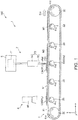
- FIG. 1 is a side view schematically illustrating the configuration of the upstream side (processing device of the invention) of a sheet manufacturing apparatus according to a first embodiment of the invention.
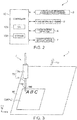
- FIG. 2 is a block diagram showing main parts of the processing device shown in FIG. 1 .
- FIG. 3 is an oblique view of the color material removal device of the processing device shown in FIG. 1 .
- FIG. 4 is a side view schematically illustrating the configuration on the downstream side of a sheet manufacturing apparatus according to the invention (first embodiment of the invention).
- FIG. 5 is a flow chart showing the sequence of steps executed by the sheet manufacturing apparatus according to the invention (first embodiment).
- FIG. 1 , FIG. 3 , and FIG. 4 (and in FIG. 8 to FIG. 13 ), the side at the top is referred to as up or above; and the side at the bottom is referred to as down or below.
- the left side is referred to as the left or the upstream side; and the right side is referred to as the right or the downstream side.
- the sheet manufacturing apparatus 100 has a processing device 1 on the upstream side.
- the processing device 1 has a conveyance mechanism 3 (X-axis moving mechanism), a Y-axis moving mechanism 5, a color material detector 4, a color material removal device 7, and a controller 10.
- the sheet manufacturing apparatus 100 has, on the downstream side, a feedstock supply device 11, a shredder 12, a defibrator 13, a classifier 14, a first web forming device 15, a cutter 16, a mixing device 17, a detangler 18, a second web forming device 19, a sheet forming device 20, a paper cutter 21, and a stacker 22.
- the sheet manufacturing apparatus 100 also has wetting unit 231, wetting unit 232, wetting unit 233, and wetting unit 234.
- the controller 10 may be configured to control the operation of parts of the feedstock supply device 11, or it may be configured to control the operation of the remaining parts of the sheet manufacturing apparatus 100 other than the parts of the processing device 1.
- the controller 10 controls the operation of parts of the controller 10
- the sheet manufacturing apparatus 100 may have a separate control means for controlling operation of the remaining parts.
- the controller 10 has a CPU (central processing unit) 101, and storage 102.
- the storage 102 stores data and control programs the CPU 101 executes to control the operation of parts.
- the sheet manufacturing method in this embodiment of the invention includes a color material detection process, an ejection area determination process, a color material removal process, a feedstock supply process, a shredding process, a defibrating process, a classification process, a first web forming process, a cutting process, a mixing process, a detangling process, a second web forming process, a sheet forming process, and a sheet cutting process.
- the sheet manufacturing apparatus 100 can execute these processes sequentially.
- the processes executed by the processing device 1 are the color material detection process, the ejection area determination process, and the color material removal process.
- the configuration on the downstream side of the sheet manufacturing apparatus 100 is described first, and the configuration on the upstream side of the sheet manufacturing apparatus 100, that is, the configuration of the processing device 1, is described next.
- the feedstock supply device 11 is the part that executes the feedstock supply process (see FIG. 5 ) supplying feedstock M1 (substrate) to the shredder 12.
- the feedstock M1 is a sheet material containing fiber (cellulose fiber), and is the material to which the processing device 1 applies the color material removal process to remove color material CM.
- the cellulose fiber may be any fibrous material containing mainly cellulose (narrowly defined cellulose) as a chemical compound, and in addition to cellulose (narrowly defined cellulose) may include hemicellulose or lignin.
- the form of the feedstock M1 is not specifically limited, and it may be woven cloth or non-woven cloth.
- the feedstock M1 may also be paper or recycled paper manufactured (regenerated) by defibrating recovered paper, or synthetic Yupo paper (R), and does not need to be recycled paper.
- the shredder 12 is the part that executes the shredding process (see FIG. 5 ) of shredding the feedstock M1 supplied from the feedstock supply device 11 in air (ambient air).
- the shredder 12 has a pair of shredder blades 121 and a chute (hopper) 122.
- the pair of shredder blades 121 shred the feedstock M1 passing therebetween, that is, cut the feedstock M1 into small shreds M2.
- the size and shape of the shreds M2 are preferably appropriate to the defibration process of the defibrator 13, and in this example are preferably pieces 100 mm or less on a side, and are further preferably pieces that are greater than or equal to 10 mm and less than or equal to 70 mm per side.
- the chute 122 is located below the pair of shredder blades 121, and in this example is funnel-shaped. As a result, the chute 122 can easily catch the shreds M2 that are shredded and dropped by the shredder blades 121.
- a wetting unit 231 is disposed beside the pair of shredder blades 121.
- the wetting unit 231 wets the shreds M2 in the chute 122.
- This wetting unit 231 has a filter (not shown in the figure) containing water, and is configured as a heaterless humidifier (or heated humidifier) that supplies a moist stream of air to the shreds M2 by passing air through the filter.
- a heaterless humidifier or heated humidifier
- the chute 122 connects to the defibrator 13 through a conduit (flow channel) 241.
- the shreds M2 collected in the chute 122 pass through the conduit 241 and are conveyed to the defibrator 13.
- the defibrator 13 is the part that executes the defibrating process (see FIG. 5 ) that defibrates the shreds M2 in a dry process in air.
- Defibrated material M3 can be produced from the shreds M2 by the defibration process of the defibrator 13.
- defibrate means to break apart and detangle into single individual fibers shreds M2 composed of many fibers bonded together.
- the resulting detangled fibers are the defibrated material M3.
- the shape of the defibrated material M3 is strands and ribbons.
- the defibrated material M3 may also contain clumps, which are multiple fibers tangled together into clumps.
- the defibrator 13 in this embodiment of the invention is configured as an impeller mill having a rotor that turns at high speed, and a liner disposed around the rotor. Shreds M2 introduced to the defibrator 13 are defibrated between the rotor and the liner.
- the defibrator 13 by rotation of the rotor, produces an air flow (current) from the shredder 12 to the classifier 14.
- shreds M2 can be suctioned from the conduit 241 to the defibrator 13.
- the defibrated material M3 can be fed through another conduit 242 to the classifier 14.
- a blower 261 is disposed in the conduit 242.
- the blower 261 is an air flow generator that produces a flow of air to the classifier 14. Conveyance of the defibrated material M3 to the classifier 14 is thereby promoted.
- the classifier 14 is the part that executes the classification process (see FIG. 2 ) of classifying the defibrated material M3 based on the length of the fibers.
- the defibrated material M3 is separated into first screened material M4-1, and second screened material M4-2 that is larger than the first screened material M4-1.
- the first screened material M4-1 is of a size appropriate to manufacturing sheets S downstream.
- the average length of the fibers is preferably greater than or equal to 100 ⁇ m and less than or equal to 10 mm.
- the second screened material M4-2 includes, for example, fiber that has not been sufficiently defibrated, and excessively agglomerated (clumped) defibrated fibers.
- the classifier 14 includes a drum 141, and a housing 142 enclosing the drum 141.
- the drum 141 is a sieve comprising a cylindrical mesh body that rotates on its center axis.
- the defibrated material M3 is introduced to the drum 141.
- defibrated material M3 that is smaller than the mesh passes through and is separated as first screened material M4-1, and defibrated material M3 that is larger than the mesh and therefore does not pass through, is separated as second screened material M4-2.
- the first screened material M4-1 drops from the drum 141.
- the second screened material M4-2 is discharged to the conduit (flow path) 243 connected to the drum 141.
- the end of the conduit 243 on the opposite end (downstream end) as the drum 141 is connected to another conduit 241.
- the second screened material M4-2 that has passed through the conduit 243 merges with the shreds M2 inside the conduit 241, and is introduced with the shreds M2 to the defibrator 13.
- the second screened material M4-2 is returned to the defibrator 13 and passes through the defibrating process with the shreds M2.
- the first screened material M4-1 from the drum 141 is dispersed while dropping through air, and descends toward the first web forming device 15 (separator).
- the first web forming device 15 is the part that executes a first web forming process (see FIG. 5 ) forming a first web M5 from the first screened material M4-1.
- the first web forming device 15 includes a mesh belt (separation belt) 151, three tension rollers 152, and a suction unit (suction mechanism) 153.
- the mesh belt 151 is an endless belt on which the first screened material M4-1 accumulates. This mesh belt 151 is mounted on three tension rollers 152. By rotationally driving the tension rollers 152, the first screened material M4-1 deposited on the mesh belt 151 is conveyed downstream.
- the size of the first screened material M4-1 is greater than or equal to the size of the mesh in the mesh belt 151. As a result, passage of the first screened material M4-1 through the mesh belt 151 is limited, and as a result the first screened material M4-1 accumulates on the mesh belt 151. Furthermore, because the first screened material M4-1 is conveyed downstream by the mesh belt 151 as the first screened material M4-1 accumulates on the mesh belt 151, the first screened material M4-1 is formed in a layer as a first web M5.
- the first screened material M4-1 may also contain dust, color material CM, and other material. Dust, for example, may be produced by shredding and defibration. Such dust and color material CM is later recovered in the storage hopper 27 described below.
- the suction unit 153 suctions air from below the mesh belt 151. As a result, dust and color material CM that has passed through the mesh belt 151 can be suctioned together with the air.
- the suction unit 153 is connected to a storage hopper 27 (recovery device) through another conduit (flow path) 244. Dust and color material CM suctioned by the suction unit 153 is captured by the storage hopper 27.
- Another conduit (flow path) 245 is also connected to the storage hopper 27.
- a blower 262 is disposed to the conduit 245. Operation of the blower 262 produces suction in the suction unit 153. This promotes formation of the first web M5 on the mesh belt 151. Dust and color material CM has been removed from the material forming the first web M5. Operation of the blower 262 causes the dust and color material CM to pass through the conduit 244 and reach the storage hopper 27.
- the housing 142 is connected to a wetting unit 232.
- the wetting unit 232 is preferably a heaterless humidifier.
- wet air is supplied into the housing 142. This wet air moistens the first screened material M4-1, and as a result can suppress sticking of the first screened material M4-1 to the inside walls of the housing 142 due to static electricity.
- Another wetting unit 235 is disposed downstream from the classifier 14.
- This wetting unit 235 is configured as an ultrasonic humidifier that mists water.
- moisture can be supplied to the first web M5, and the moisture content of the first web M5 can thereby be adjusted.
- This adjustment can also suppress sticking of the first web M5 to the mesh belt 151 due to static electricity.
- the first web M5 easily separates from the mesh belt 151 at the tension roller 152 from where the mesh belt 151 returns to the upstream side.
- the cutter 16 is a part that executes a cutting process (see FIG. 5 ) of cutting the first web M5 that has separated from the mesh belt 151.
- the cutter 16 has a propeller 161 that is rotationally supported, and a housing 162 that houses the propeller 161.
- the first web M5 is cut into pieces as it is fed into the rotating propeller 161.
- the cut first web M5 forms segments M6.
- the segments M6 then drop down in the housing 162.
- the housing 162 is connected to another wetting unit 233.
- the wetting unit 233 is preferably a heaterless humidifier. As a result, wet air is supplied into the housing 162. This wet air suppresses sticking of the segments M6 to the propeller 161 and to the inside walls of the housing 162 due to static electricity.
- a mixing device 17 is disposed on the downstream side of the cutter 16.
- the mixing device 17 is the part that executes a mixing process (see FIG. 5 ) of mixing the segments M6 with resin P1.
- the mixing device 17 includes a resin supply device 171, a conduit (flow path) 172, and a blower 173.
- the conduit 172 connects to the housing 162 of the cutter 16 and the housing 182 of the detangler 18, and is a flow path through which a mixture M7 of the segments M6 and resin P1 passes.
- the resin supply device 171 connects to the conduit 172.
- the resin supply device 171 has a screw feeder 174. By rotationally driving the screw feeder 174, the resin P1 can be supplied in powder or particle form to the conduit 172.
- the resin P1 supplied to the conduit 172 is mixed with the segments M6, forming the mixture M7.
- the resin P1 bonds fibers together in a downstream process, and may be a thermoplastic resin or a thermosetting resin, but is preferably a thermoplastic resin.
- thermoplastic resins include AS resin, ABS resin, polyethylene, polypropylene, ethylenevinylacetate copolymer (EVA), or other polyolefin, denatured polyolefins, polymethylmethacrylate or other acrylic resin, polyvinyl chloride, polystyrene, polyethylene terephthalate, polybutylene terephthalate or other polyesters, nylon 6, nylon 46, nylon 66, nylon 610, nylon 612, nylon 11, nylon 12, nylon 6-12, nylon 6-66 or other polyimide (nylon), polyphenylene ether, polyacetal, polyether, polyphenylene oxide, polyether ether ketone, polycarbonate, polyphenylene sulfide, thermoplastic polyimide, polyether imide, aromatic polyester, or other liquid crystal polymer, styrenes, polyolefins
- Additives other than resin P1 may also be supplied from the resin supply device 171, including, for example, coloring agents for adding color to the fiber, anti-blocking agents for suppressing clumping of the fiber and clumping of the resin P1, and flame retardants for making the fiber and manufactured sheets difficult to burn. Compounds already incorporating such other additives with the resin P1 may also be supplied.
- the blower 173 is disposed to the conduit 172 downstream from the resin supply device 171.
- the segments M6 and resin P1 are also mixed by the action of a rotating unit such as blades of the blower 173.
- the blower 173 is configured to produce an air current toward the detangler 18. This air current can also mix the segments M6 and resin P1 inside the conduit 172.
- the mixture M7 can be introduced to the detangler 18 as a uniform dispersion of the segments M6 and resin P1.
- the segments M6 in the mixture M7 are further detangled into smaller fibers while travelling through the conduit 172.
- the detangler 18 is the part that executes the detangling process (see FIG. 5 ) that detangles interlocked fibers in the mixture M7.
- the detangler 18 includes a drum 181 and a housing 182 that houses the drum 181.
- the drum 181 is a sieve comprising a cylindrical mesh body that rotates on its center axis.
- the mixture M7 is introduced to the drum 181.
- fiber in the mixture M7 that is smaller than the mesh can pass through the drum 181.
- the mixture M7 is detangled in this process.
- the mixture M7 that is detangled in the drum 181 is dispersed while dropping through air, and falls to the second web forming device 19 located below the drum 181.
- the second web forming device 19 is the part that executes the second web forming process (see FIG. 5 ) forming a second web M8 from the mixture M7.
- the second web forming device 19 includes a mesh belt (separation belt) 191, tension rollers 192, and a suction unit (suction mechanism) 193.
- the mesh belt 191 is an endless belt on which the mixture M7 accumulates. This mesh belt 191 is mounted on four tension rollers 192. By rotationally driving the tension rollers 192, the mixture M7 deposited on the mesh belt 191 is conveyed downstream.
- the mixture M7 on the mesh belt 191 is larger than the mesh in the mesh belt 191. As a result, the mixture M7 is suppressed from passing through the mesh belt 191, and therefore accumulates on the mesh belt 191.
- the mixture M7 is conveyed downstream by the mesh belt 191 as the mixture M7 accumulates on the mesh belt 191, and is formed in a layer as the second web M8.
- the suction unit 193 suctions air down from below the mesh belt 191. As a result, the mixture M7 can be pulled onto the mesh belt 191, and accumulation of the mixture M7 on the mesh belt 191 is thereby promoted.
- Another conduit (flow path) 246 is connected to the suction unit 193.
- a blower 263 is also disposed to the conduit 246. Operation of the blower 263 produces suction in the suction unit 193.
- Another wetting unit 234 is connected to the housing 182. Like the wetting unit 231 described above, the wetting unit 234 is preferably a heaterless humidifier. As a result, wet air is supplied into the housing 182. By humidifying the inside of the housing 182 by adding wet air, sticking of the mixture M7 to the inside walls of the housing 182 due to static electricity can be suppressed.
- Another wetting unit 236 is disposed below the detangler 18.
- This wetting unit 236 is preferably configured as an ultrasonic humidifier similarly to the wetting unit 235 described above.
- moisture can be supplied to the second web M8, and the moisture content of the second web M8 can thereby be adjusted.
- This adjustment can also suppress sticking of the second web M8 to the mesh belt 191 due to static electricity.
- the second web M8 easily separates from the mesh belt 191 at the tension roller 192 from where the mesh belt 191 returns to the upstream side.
- the combined amount of moisture (total moisture content) added by wetting unit 231 to wetting unit 236 is, for example, preferably greater than or equal to 0.5 parts by weight and less than or equal to 20 parts by weight per 100 parts by weight of the material before adding moisture.
- a sheet forming device 20 is disposed downstream from the second web forming device 19.
- the sheet forming device 20 is the part that executes the sheet forming process (see FIG. 5 ) forming sheets S from the second web M8.
- This sheet forming device 20 includes a calender 201 and a heater 202.
- the calender 201 comprises a pair of calender rollers 203, and the second web M8 can be compressed without heating (without melting the resin P1) by passing the second web M8 between the calender rollers 203. This process increases the density of the second web M8. The second web M8 is then conveyed toward the heater 202.
- one of the pair of calender rollers 203 is a drive roller that is driven by operation of a motor (not shown in the figure), and the other is a driven roller.
- the heater 202 has a pair of heat rollers 204, which can heat while compressing the second web M8 passing between the heat rollers 204.
- the combination of heat and pressure melts the resin P1 in the second web M8, and bonds fibers through the molten resin P1. As a result, a sheet S is formed.
- one of the pair of heat rollers 204 is a drive roller that is driven by operation of a motor (not shown in the figure), and the other is a driven roller.
- a paper cutter 21 is disposed downstream from the sheet forming device 20.
- the paper cutter 21 is the part that executes the sheet cutting process (see FIG. 5 ) that cuts the continuous sheet S into single sheets S.
- the paper cutter 21 includes a first cutter 211 and a second cutter 212.
- the first cutter 211 cuts the sheet S in the direction crosswise to the conveyance direction of the sheet S.
- the second cutter 212 is downstream from the first cutter 211, and cuts the sheets S in the direction parallel to the conveyance direction of the sheet S.
- Sheets S of a desired size are produced by the cutting action of the first cutter 211 and the second cutter 212.
- the sheets S are then conveyed further downstream and stacked in a stacker 22.
- the feedstock M1 that is remanufactured into sheets S is recovered paper that was previously printed on.
- the feedstock M1 before being introduced to the feedstock supply device 11 has a recorded layer (printed layer) PL that was used to record information using black or color toner or ink, dyes, pigments, or other color material CM. See FIG. 1 and FIG. 3 .
- a recorded layer printed layer
- CM color material
- a processing device 1 disposed on the upstream side of the sheet manufacturing apparatus 100 in this embodiment is therefore configured to remove color material CM from the feedstock M1. This processing device 1 is described below.
- the processing device 1 particularly improves the efficiency of removing color material CM when the color material CM is toner or ink.
- the processing device 1 has a conveyance mechanism 3, a Y-axis moving mechanism 5, a color material detector 4, a color material removal device 7, and a controller 10 (see Fig. 2 ). Note that the processing device 1 is preferably disposed in or connected to the feedstock supply device 11.
- the conveyance mechanism 3 conveys the feedstock M1 downstream, that is, forward on the X-axis (main scanning direction).
- the conveyance mechanism 3 includes a glue belt 31, two tension rollers 32, and a plurality of idler rollers 33.
- the glue belt 31 is an endless belt with a sticky surface.
- the sticky surface of the glue belt 31 holds the feedstock M1 firmly and stable during the color material detection process of the color material detector 4, and the color material removal process of the color material removal device 7.
- a plurality of feedstocks M1 can be loaded on the glue belt 31.
- the feedstocks M1 on the glue belt 31 may be oriented in the same direction, or not.
- the two tension rollers 32 are disposed on the upstream end and the downstream end in the conveyance direction of the glue belt 31 with a gap therebetween, and the glue belt 31 is mounted on the tension rollers 32.
- one tension roller 32 is connected to a motor (not shown in the figure), and is a drive roller that turns in the direction of arrow ⁇ 32 by driving the motor.
- the other tension roller 32 is a driven roller to which torque is transferred from the drive roller through the glue belt 31, and which turns in the same direction as the drive roller, that is, the direction of arrow ⁇ 32.
- the conveyance mechanism 3 can also vary the conveyance speed of the feedstock M1.
- a plurality of idler rollers 33 are disposed with a gap therebetween between the two tension rollers 32. Each idler roller 33 can turn in conjunction with driving the glue belt 31 in the same direction of rotation ⁇ 33 as the direction of rotation of the tension rollers 32.
- the idler rollers 33 can prevent the glue belt 31 from sagging, and therefore enable conveying the feedstock M1 stably.
- the Y-axis moving mechanism 5 supports the color material removal device 7 movably bidirectionally on the Y-axis (sub-scanning direction).
- the configuration of the Y-axis moving mechanism 5 is not specifically limited, and may be configured with a ball screw disposed parallel to the Y-axis, a motor as the drive source that rotates the ball screw, and a linear guide that guides the color material removal device 7 on the Y-axis in conjunction with rotation of the ball screw.
- the conveyance mechanism 3 and Y-axis moving mechanism 5 can move the nozzle 731 of the color material removal device 7 and the feedstock M1 (substrate) relative to each other on the x-y plane.
- the processing device 1 sheet manufacturing apparatus 100 thus comprises a moving means for moving the nozzle 731 of the color material removal device 7 and the feedstock M1 (substrate) relative to each other.
- the nozzle 731 can be positioned opposite the color material CM.
- Particles RM can then be ejected from the nozzle 731 to the color material CM so that the particles RM strike the color material CM. Bombardment of the color material CM with the particles RM can remove the color material CM from the feedstock M1.
- the processing device 1 also has a color material detector 4 that detects the color material CM (recorded layer PL) on the feedstock M1 (substrate) before removing the color material CM.
- the color material detector 4 is a part that is disposed along the glue belt 31 for executing the color material detection process (see FIG. 5 ) to detect color material CM on the feedstock M1.
- the controller 10 ejection area decision device determines the area on the feedstock M1 (substrate) to which to eject particles RM from the color material removal device 7.
- the color material detector 4 in this example has an imaging device 41 embodied by a CCD (charge coupled device) camera.
- the imaging device 41 is disposed and secured facing down.
- the imaging device 41 can take a gray scale picture of the feedstock M1.
- the captured image is then sent to the controller 10, which executes an imaging process extracting the location of the color material CM (recorded layer PL) on the feedstock M1.
- This imaging process is not specifically limited, but is preferably a digitizing process.
- a threshold is set, and image areas exceeding the threshold are determined to be areas where there is color material CM.
- the imaging area of the imaging device 41 is large enough to enable imaging the entire feedstock M1 if the feedstock M1 is directly below the imaging device 41.
- the processing device 1 can determine the area on the feedstock M1 (substrate) to which to eject particles RM from the color material removal device 7.
- the controller 10 functions as an ejection area decision device, and executes the ejection area determination process (see FIG. 5 ).
- the controller 10 functions as an ejection area decision device, and executes the ejection area determination process (see FIG. 5 ).
- particles RM ejected from the nozzle 731 of the color material removal device 7 can be focused on the color material CM, and color material CM can be quickly removed from the feedstock M1.
- the color material removal device 7 is disposed above the glue belt 31 and downstream from the color material detector 4.
- the color material removal device 7 ejects the particles RM (cellulose) to the feedstock M1 (substrate) containing color material CM, and executes the color material removal process (see FIG. 5 ) that removes the color material CM from the feedstock M1 (substrate).
- the color material removal device 7 has a holding tank 71.
- the holding tank 71 is a tank for holding the particles RM. When the holding tank 71 becomes empty, the holding tank 71 is refilled or replaced with another holding tank 71 holding a sufficient amount of particles RM.
- the color material removal device 7 also has an ejector 72 for ejecting the particles RM to the feedstock M1.
- the ejector 72 includes a conduit 73 and a blower 74.
- One end of the conduit 73 connects to the holding tank 71, and the opposite end is a nozzle 731 with the opening pointing down. Particles RM passing from the holding tank 71 through the conduit 73 are ejected from the nozzle 731.
- the velocity (ejection velocity) of the ejected particles RM is set appropriately to the size of the particles RM.
- the color material removal device 7 may be supported vertically on the Z-axis. This configuration enables adjusting the height of the nozzle 731 appropriately to the thickness of the feedstock M1.
- a blower 74 is disposed along the length of the conduit 73.
- the blower 74 in this example can produce a downward stream of air at a pressure ranging from greater than or equal to 0.1 MPa and less than or equal to 0.5 MPa.
- the particles RM pass through the conduit 73 and can be desirably ejected from the nozzle 731. Some of the particles RM that are ejected will strike the color material CM on the surface of the feedstock M1, and color material CM that is embedded in the feedstock M1. Impact of the particles RM striking the color material CM can separate the color material CM from the feedstock M1. In this way, the particles RM are a removal powder for separating and removing the color material CM from the feedstock M1.
- the particles RM function as an excellent removal powder for removing the color material CM.
- the particles RM that are ejected include particles RM that strike the color material CM, and particles RM that strike the feedstock M1 without hitting color material CM. In this case, some of the fiber in the feedstock M1 may also be removed.
- the decolorized feedstock M1 from which color material CM was removed is then conveyed to the feedstock supply device 11, and regenerated (manufactured) as a sheet S through the subsequent processes described above.
- the sheets S are high quality sheets from which color material CM, which could become an impurity in the remanufactured sheet, has been removed.
- particles RM containing cellulose are used to remove color material CM from the feedstock M1. Because the feedstock M1 contains cellulose, damage to the feedstock M1 by impact with the particles RM can be suppressed when particles RM strike the feedstock M1 while removing the color material CM.
- the feedstock M1 can be conveniently used to remanufacture sheets as described above.
- the cellulose contained in the particles RM is preferably the same as the cellulose contained in the feedstock M1 described above, may be any fibrous material containing mainly cellulose (narrowly defined cellulose) as a chemical compound, and in addition to cellulose (narrowly defined cellulose) may include hemicellulose or lignin.
- the average particle diameter of the particles RM is, for example, greater than or equal to 0.1 ⁇ m and less than or equal to 50 ⁇ m. Considering that the width of cellulose fibers contained in the feedstock M1 is generally about 10 ⁇ m to 30 ⁇ m, it is difficult for particles RM greater than 50 ⁇ m to efficiently strip color material CM adhering to the surface of fibers.
- the moisture content of the particles RM is preferably greater than or equal to 5% and less than or equal to 20%. Because mass increases as the moisture content increases, the kinetic energy of the particles RM also increases, and the particles RM can more efficiently remove color material CM. However, if the moisture content exceeds 20%, the particles RM may clump together or stick to the inside walls of the holding tank 71 and conduit 73 (nozzle 731), interfering with efficient particle ejection.
- idler roller 33a One of the idler rollers 33 is located below the nozzle 731 with the glue belt 31 therebetween (the idler roller 33 directly below the nozzle 731 is referred to below as idler roller 33a).
- This idler roller 33a can support the feedstock M1 and the glue belt 31 from below.
- the particles RM ejected from the nozzle 731 can desirably strike the color material CM.
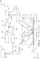
- FIG. 6 is a side view schematically illustrating the configuration of the upstream side (processing device of the invention) of a sheet manufacturing apparatus according to a second embodiment of the invention.
- FIG. 7 is a side view schematically illustrating a separating device of the processing device shown in FIG. 6 .
- a processing device, a sheet manufacturing apparatus, a processing method, and a sheet manufacturing method according to a second embodiment of the invention are described below with reference to the accompanying figures, focusing on differences with the foregoing embodiment and omitting further description of similar configurations.
- This embodiment is the same as the first embodiment described above except for the configuration of the processing device.
- the conveyance mechanism 3 in the first embodiment described above is a belt conveyor, but the embodiment of the configuration shown in FIG. 6 is configured to hold the feedstock M1 by means of suction on a stage while conveying the feedstock M1, or more specifically comprises a platen 34.
- This platen 34 may be supported movably on both the X-axis and the Y-axis.
- a belt similar to the first embodiment can also be used.
- the processing device 1 in this embodiment has an airtight housing 8, and the nozzle 731 of the color material removal device 7 is disposed inside the housing 8.
- This housing 8 includes a box-like case 81, and a seal 82 and another seal 83 disposed below the case 81.
- the case 81 covers part of the color material removal device 7 at the distal end (the nozzle 731 end) from the blower 74.
- Seals 82 are rollers that are disposed to both X-axis sides of the case 81 and rotate on the Y-axis.
- the other seal 83 is disposed to both Y-axis sides of the case 81, and is shaped like a belt extending on the X-axis. Seals 82 and seals 83 can contact the platen 34 and the feedstock M1 moving forward (sliding) on the X-axis. As a result, the inside of the housing 8 (case 81) can be kept airtight.
- the color material CM is removed from the feedstock M1 inside the housing 8 in this configuration.
- the particles RM ejected from the nozzle 731 of the color material removal device 7, and color material CM removed by the particles RM can be prevented from dispersing and soiling the surrounding area.
- maintenance of the inside of the processing device 1 is simplified.
- the nozzle 731 is directed down from the upstream side, that is, at an angle downward and to the right in FIG. 6 .
- the processing device 1 also has a collection unit 9.
- the collection unit 9 collects the particles RM and color material CM. More specifically, the collection unit 9 includes a vacuum 91, a separator 92, a particle storage tank 93, and a color material storage tank 94.
- the vacuum 91 and separator 92 connect through a conduit (flow path) 991.
- the separator 92 and particle storage tank 93 connect through another conduit (flow path) 992.
- the particle storage tank 93 connects through another conduit (flow path) 993 to a junction with the conduit 73 of the color material removal device 7.
- the separator 92 and color material storage tank 94 connect through another conduit (flow path) 994.
- the collection unit 9 of the processing device 1 has a vacuum 91 that collects the particles RM and color material CM after the color material CM is removed.
- the vacuum 91 includes a vacuum head 911, a duct 912, and a storage tank 913.
- the vacuum head 911 connects to the downstream side of the nozzle 731.
- the vacuum head 911 is conically shaped when seen from the side, and is directed at a downward left angle in FIG. 6 with the distal end open.
- the duct 912 is a conduit connecting the vacuum head 911 to the storage tank 913.
- the particles RM and color material CM collected by the vacuum head 911 pass through the duct 912 and enter the storage tank 913.
- a blower (not shown in the figure) may be connected to the duct 912. The blower produces suction in the vacuum head 911, enabling collecting the particles RM and color material CM through the vacuum head 911.
- the storage tank 913 is a part that temporarily stores the particles RM and color material CM from the duct 912.
- a vacuum 91 thus comprised can collect the particles RM and color material CM that is prevented from dispersing by the housing 8. As a result, particles RM and color material CM can be prevented from being left on the feedstock M1.
- the collection unit 9 of the processing device 1 also has a separator 92 that separates the collected particles RM and color material CM.
- the separator 92 in this example is configured to use differences in the static charge of the color material CM and particles RM to separate the particles RM and color material CM.
- the separator 92 includes a discharge device 921, a conveyance device 922, a charger 923, a blade 924, another conveyance device 925, a charger 926, and a blade 927.
- the discharge device 921 is a device that discharges the particles RM and color material CM conveyed thereto through conduit 991 to a conveyance device 922 therebelow.
- the conveyance device 922 includes an endless belt 922a, and two tension rollers 922b on which the endless belt 922a is mounted.
- the particles RM and color material CM discharged from the discharge device 921 accumulate in a layer on the endless belt 922a as a result of the tension rollers 922b turning on the Y-axis.
- the charger 923 is a negative charger that negatively charges the particles RM and color material CM on the endless belt 922a. As a result, the particles RM and color material CM are negatively charged, but due to the properties of the color material CM, the color material CM holds a stronger negative charge than the particles RM.
- the conveyance device 925 is disposed above the conveyance device 922.
- the conveyance device 925 comprises an endless belt 925a, and two tension rollers 925b on which the endless belt 925a is mounted.
- the charger 926 is a positive charger that positively charges the endless belt 925a.
- color material CM that holds a stronger negative charge than the particles RM is pulled from the one endless belt 922a to the other endless belt 925a, and more color material CM sticks to the endless belt 925a than particles RM.
- color material CM is removed from the endless belt 922a, leaving the particles RM.
- the blade 924 touches the endless belt 922a, and wipes residual particles RM from the endless belt 922a.
- the removed particles RM are collected in the particle storage tank 93.
- the other blade 927 contacts the endless belt 925a, and wipes color material CM from the endless belt 925a.
- the color material CM that is removed collects in the color material storage tank 94.
- the color material CM collected in the color material storage tank 94 may then be discarded.
- the separator 92 thus comprised can separate particles RM that can be reused from color material CM that can be discarded.
- the collection unit 9 of the processing device 1 also has a conduit 993 that returns the recovered particles RM to the conduit 73 of the color material removal device 7.
- particles RM that have passed through the conduit 993 merge in the conduit 73 with the particles RM discharged from the holding tank 71 of the color material removal device 7.
- the color material removal device 7 can reuse the particles RM returned from the conduit (flow path) 993 to remove color material CM.
- particles RM that can be reused can be recycled and prevented from being wastefully discarded.
- a configuration such as a screw feeder or circle feeder that facilitates passage of the particles RM through the conduit 993 may be disposed to the conduit 993.
- FIG. 8 is a side view schematically illustrating the configuration of the separating device of the processing device disposed on the upstream side of a sheet manufacturing apparatus according to a third embodiment of the invention.
- a processing device, a sheet manufacturing apparatus, a processing method, and a sheet manufacturing method according to a third embodiment of the invention are described below with reference to the accompanying figures, focusing on differences with the foregoing embodiments and omitting further description of similar configurations.
- This embodiment is the same as the second embodiment described above except for the configuration of the separator of the collection unit.
- the separator 95 of the collection unit 9 comprises a conduit 951, a conveyance device 952, a charger 953, a charger 954, and a blade 955.
- the storage tank 913 is omitted in this embodiment of the invention.
- the conduit 951 is a connector conduit between conduit 991 and conduit 992.
- the conveyance device 952 includes an endless belt 952a of which part is exposed inside the conduit 951, and three tension rollers 952b on which the endless belt 952a is mounted.
- the charger 953 is disposed on the upstream side of the conduit 951 upstream of where the endless belt 952a is exposed, and is a negative charger that negatively charges the particles RM and color material CM passing through the conduit 951. As a result, the particles RM and color material CM are both negatively charged, but due to their properties, the color material CM holds a stronger negative charge than the particles RM.
- the charger 954 is a positive charger that positively charges the endless belt 925a.
- color material CM that holds a stronger negative charge than the particles RM is pulled to the other endless belt 952a when passing below the endless belt 952a, and more color material CM sticks to the endless belt 952a than particles RM.
- the particles RM pass through conduit 951 to the conduit 992.
- the blade 955 touches the endless belt 952a, and wipes color material CM from the endless belt 952a.
- the removed color material CM is collected in the color material storage tank 94.
- the separator 95 thus comprised can separate particles RM that can be reused from color material CM that can be discarded.
- FIG. 9 is a side view schematically illustrating the configuration of the upstream side (processing device of the invention) of a sheet manufacturing apparatus according to a fourth embodiment of the invention.
- a processing device, a sheet manufacturing apparatus, a processing method, and a sheet manufacturing method according to a fourth embodiment of the invention are described below with reference to the accompanying figures, focusing on differences with the foregoing embodiments and omitting further description of similar configurations.
- This embodiment is the same as the second or third embodiment described above except for the configuration of the color material removal device.
- the ejector 72 of the color material removal device 7 in this embodiment of the invention is a double-walled structure 77 including an internal conduit 75, and an external conduit 76 in which the internal conduit 75 is inserted.
- the internal conduit 75 is a hard conduit with a nozzle 751 open in the bottom end.
- the external conduit 76 is a conduit of a harder material than the internal conduit 75, and the internal conduit 75 is inserted to the external conduit 76.
- the external conduit 76 also has a nozzle 761 open in the bottom end.
- the nozzle 751 of the internal conduit 75 protrudes below the bottom end of the nozzle 761 of the external conduit 76.
- the double-walled structure 77 comprising an internal conduit 75 and an external conduit 76 functions as a nozzle from which particles RM are sprayed down from at least one of the nozzle 751 of the internal conduit 75 and the nozzle 761 of the external conduit 76.
- the nozzle 751 of the internal conduit 75 functions as a nozzle from which particles RM are sprayed.
- the nozzle 761 of the external conduit 76 functions as an air nozzle from which air GS (gas) is sprayed in a downward direction. More specifically, air GS (gas) is sprayed down from the nozzle 761 of the external conduit 76.
- the color material removal device 7 having a double-walled structure 77 configured as described above can operate in the following three states.
- the first state is a state in which particles RM are discharged from the nozzle 751 of the internal conduit 75 while air GS is discharged from the nozzle 761 of the external conduit 76 as illustrated in FIG. 9 .
- the air GS discharged from the external conduit 76 functions as an air curtain around the particles RM discharged from the internal conduit 75.
- dispersion of the particles RM before the particles RM reach the recorded layer PL (color material CM) on the feedstock M1 can be prevented, and as a result causes the particles RM to strike a relatively confined area of the recorded layer PL with great force.
- This impact of the particles RM can quickly and efficiently remove the recorded layer PL (color material CM) from the feedstock M1.
- the air curtain can also prevent a drop in the discharge velocity of the particles RM.
- the second state is a state in which particles RM are discharged from the nozzle 751 of the internal conduit 75 but the discharge of air GS is stopped (that is, air GS is not discharged).
- the area of the recorded layer PL impacted by the particles RM is larger than an in the first state.
- the third state is a state in which particles RM are not discharged but air GS is discharged from the nozzle 761 of the external conduit 76.
- particles RM, color material CM that was removed, or other material is left on the platen 34 after the feedstock M1 has been removed, this third state enables dispersing any remaining material and cleaning the platen 34 (or belt 31).
- FIG. 10 is a side view schematically illustrating the configuration of the upstream side (processing device of the invention) of a sheet manufacturing apparatus according to a fifth embodiment of the invention.
- a processing device, a sheet manufacturing apparatus, a processing method, and a sheet manufacturing method according to a fifth embodiment of the invention are described below with reference to the accompanying figures, focusing on differences with the foregoing embodiments and omitting further description of similar configurations.
- This embodiment is the same as the fourth embodiment described above except for the function of the double-walled structure of the color material removal device.
- the nozzle 761 of the external conduit 76 of the double-walled structure 77 functions as the nozzle that ejects the particles RM.
- the nozzle 751 of the internal conduit 75 functions as a suction nozzle that vacuums up the color material CM together with the particles RM used to remove the color material CM.
- the particles RM are vacuumed up together with the color material CM by the nozzle 751 of the internal conduit 75.
- This suctioning action can prevent dispersion of the particles RM before the particles RM reach the recorded layer PL (color material CM) on the feedstock M1, and as a result causes the particles RM to strike a relatively confined area of the recorded layer PL with great force.
- This impact of the particles RM can quickly and efficiently remove the recorded layer PL (color material CM) from the feedstock M1. Dispersion of the particles RM that struck the feedstock M1, and the color material CM that was removed, can also be prevented.
- the internal conduit 75 is also preferably connected to the duct 912 of the collection unit 9 (not shown in FIG. 10 ). In this case, the particles RM and color material CM suctioned through the internal conduit 75 can be collected in the collection unit 9.
- the inside diameter (and outside diameter) of the part of the external conduit 76 extending from some lengthwise point to the nozzle 761 also decreases gradually to the distal bottom end. By reducing the inside diameter, the nozzle 761 is constricted and forceful ejection of the particles RM is promoted.
- a similar arrangement can be used in the other embodiments.
- FIG. 11 is a side view schematically illustrating the configuration of the upstream side (processing device of the invention) of a sheet manufacturing apparatus according to a sixth embodiment of the invention.
- a processing device, a sheet manufacturing apparatus, a processing method, and a sheet manufacturing method according to a sixth embodiment of the invention are described below with reference to the accompanying figures, focusing on differences with the foregoing embodiments and omitting further description of similar configurations.
- This embodiment is the same as the fourth embodiment described above except for the function of the double-walled structure of the color material removal device.
- both the nozzle 751 of the internal conduit 75 and the nozzle 761 of the external conduit 76 of the double-walled structure 77 function as nozzles that eject the particles RM.
- the particles RM discharged from the nozzle 751 of the internal conduit 75 (referred to below as particles RM1), and the particles RM discharged from the nozzle 761 of the external conduit 76 (referred to below as particles RM2) differ by one or both of the particle diameter and moisture content.
- the internal conduit 75 is connected to a holding tank 71 (not shown in FIG. 11 ) storing the particles RM1, and the external conduit 76 is connected to another holding tank 71 (not shown in FIG. 11 ) storing the particles RM2.
- the double-walled structure 77 configured as described above can operate in the following three states.
- the first state is the state shown in FIG. 11 in which particles RM2 are discharged while also discharging particles RM1.
- the second state is a state in which particles RM1 are discharged but particles RM2 are not discharged.
- the third state is a state in which the particles RM1 are not discharged but the particles RM2 are discharged.
- the three states can be desirably selected.
- particles RM1 or particles RM2 can be discharged appropriately to the distribution of the color material CM. More specifically, when removing color material CM, particles RM1 can be discharged to those areas desirably bombarded with particles RM1, and particles RM2 can be discharged to those areas desirably bombarded with particles RM2.
- particles RM1 and particles RM2 are described as two different types of particles RM that differ by a certain parameter, but the invention is not so limited and the particles RM may be the same.
- the discharge velocity of the particles RM1 discharged from the internal conduit 75, and the discharge velocity of the particles RM2 discharged from the external conduit 76, may be the same or different. If the discharge velocities of the particles RM differ, the discharge velocity of the particles RM1 may be greater than the discharge velocity of the particles RM2, or the discharge velocity of the particles RM1 may be less than the discharge velocity of the particles RM2.
- a configuration enabling adjusting the discharge velocity is also conceivable.
- FIG. 12 is a side view schematically illustrating the configuration of the upstream side (processing device of the invention) of a sheet manufacturing apparatus according to a seventh embodiment of the invention.
- a processing device, a sheet manufacturing apparatus, a processing method, and a sheet manufacturing method according to a seventh embodiment of the invention are described below with reference to the accompanying figures, focusing on differences with the foregoing embodiments and omitting further description of similar configurations.
- This embodiment is the same as the second or third embodiment described above except for the configuration of the color material removal device.
- the color material removal device 7 in this embodiment of the invention has three (a plurality of) ejectors 72 arrayed on the X-axis (identified below in order from the negative X-axis side as ejector 72A, ejector 72B, and ejector 72C).
- Ejector 72A, ejector 72B, and ejector 72C are disposed on different orientations inside the housing 8, and as a result the color material removal device 7 has three (a plurality of) nozzles 731 that discharge the particles RM from different directions.
- Particles RM are discharged from the nozzle 731 of ejector 72A descending at an angle to the right as seen in FIG. 12 .
- Particles RM are discharged from the nozzle 731 of ejector 72B descending vertically on the Z-axis as seen in FIG. 12 .
- Particles RM are discharged from the nozzle 731 of ejector 72C descending at an angle to the left as seen in FIG. 12 .
- the color material removal device 7 thus comprised improves the efficiency of color material CM removal as a result of the particles RM striking the color material CM on the feedstock M1 from three different directions.
- a configuration enabling adjusting the discharge velocity of the particles RM from the nozzles 731 is also conceivable.
- the color material removal device 7 also enables desirably selecting which of the three ejectors 72 discharge particles RM and which ejectors 72 do not discharge particles RM to remove the color material CM.
- the particles RM discharged from each of the nozzles 731 may differ by one or both of the particle diameter and moisture content.
- three types of particles RM that differ by at least one parameter can therefore be used to bombard the color material CM on the feedstock M1 and remove the color material CM.
- areas that are preferably struck by particles RM of a first type discharged from ejector 72A may be bombarded by particles RM of the first type
- areas that are preferably struck by particles RM of a second type discharged from ejector 72B may be bombarded by particles RM of the second type
- areas that are preferably struck by particles RM of a third type discharged from ejector 72C may be bombarded by particles RM of the third type.
- the arrangement of the three ejectors 72 is not limited to the arrangement shown in FIG. 12 .
- this embodiment describes a configuration having three ejectors 72, but the invention is not so limited and there may be only two or four or more.
- the plural ejectors 72 may include ejectors 72 that discharge the particles RM in the same direction.
- FIG. 13 is a side view schematically illustrating the configuration of the upstream side (processing device of the invention) of a sheet manufacturing apparatus according to an eighth embodiment of the invention.
- a processing device, a sheet manufacturing apparatus, a processing method, and a sheet manufacturing method according to an eighth embodiment of the invention are described below with reference to the accompanying figures, focusing on differences with the foregoing embodiments and omitting further description of similar configurations.
- This embodiment is the same as the first embodiment described above except for the configuration of the color material removal device.
- the color material removal device 7 in this embodiment of the invention has a coolant storage tank 78 storing a refrigerant RF.
- This coolant storage tank 78 connects through a conduit 79 to the conduit 73 of an ejector 72.
- the color material removal device 7 is configured to discharge a refrigerant RF with the particles RM from the nozzle 731. All the other embodiments may be adapted in the same way.
- Heat is produced when the particles RM strike the color material CM. Depending on the amount of heat generated, this can melt the color material CM (particularly when the color material CM is toner) and result in the color material CM binding with the feedstock M1. Production of such heat can be suppressed by discharging refrigerant RF with the particles RM. As a result, the color material CM can be cooled, melting of the color material CM can be minimized, and the color material CM can therefore be efficiently removed. Cooling can also make the color material CM (resin) brittle, further improving the efficiency of color material CM removal. The difference in the coefficients of thermal expansion of the color material CM and the cellulose (fiber) in the feedstock M1 when cooled can also be used to further improve efficiency of removing color material CM.
- the refrigerant RF is not specifically limited, and may be particles (a powder) of ice or dry ice. Note that dry ice is carbon dioxide in solid form.
- the color material removal device 7 can switch between discharging and not discharging refrigerant RF.
- discharge of refrigerant RF can also be applied to the sixth embodiment and seventh embodiment described above.
- processing device sheet manufacturing apparatus, processing method, and sheet manufacturing method of the invention may also be embodied by any two or more configurations (features) described herein.
- the device that moves the nozzles of the color material removal device and the feedstock (substrate) relatively to each other includes a conveyance device and Y-axis moving mechanism in the embodiment described above, but the invention is not so limited.
- the color material removal device may be supported to move independently on the X-axis and the Y-axis.
- the controller may also connect to another communication device through a network.
- the other communication device is not specifically limited, and may be a personal computer, digital camera, smartphone, or tablet computer, for example.
- the sheet manufacturing apparatus may be configured without the configuration on the downstream side in FIG. 4 .
- the feedstock from which color material was removed by the processing device is used as is without further processing, that is, the feedstock can be used for printing again.
Landscapes
- Engineering & Computer Science (AREA)
- Mechanical Engineering (AREA)
- Chemical Kinetics & Catalysis (AREA)
- Wood Science & Technology (AREA)
- Health & Medical Sciences (AREA)
- Chemical & Material Sciences (AREA)
- Life Sciences & Earth Sciences (AREA)
- General Chemical & Material Sciences (AREA)
- Toxicology (AREA)
- Nonwoven Fabrics (AREA)
- Paper (AREA)
- Accessory Devices And Overall Control Thereof (AREA)
- Cleaning In Electrography (AREA)
- Dry Formation Of Fiberboard And The Like (AREA)
Abstract
Description
- The present invention relates to a processing device, a sheet manufacturing apparatus, a processing method, and a sheet manufacturing method.
- As concerns about the environment and environmental awareness have increased, there is growing interest in not only reducing the amount of paper (recording media) that is used in the workplace, but also in recycling and remanufacturing paper in the workplace.
-
JP-A-2000-284657 - However, when the recorded layer is sprayed with a blast grit in the recording media recycling method described in
JP-A-2000-284657 - An objective of the present invention is to provide a processing device, a sheet manufacturing apparatus, a processing method, and a sheet manufacturing method that suppress damage to a substrate when removing color material from a substrate, and are useful for recycling the substrate after color material is removed.
- The present invention is directed to solving at least part of the foregoing problem, and may be embodied as described below.
- A processing device according to an aspect of the invention has a color material removal device having at least one discharge nozzle configured to discharge particles containing cellulose to a substrate holding color material, and remove the color material from the substrate.
- Thus comprised, a powder of particles containing cellulose is used to remove color material from a substrate. As described further below, because the substrate contains cellulose, damage to the substrate caused by the particles striking the substrate when removing the color material can be suppressed. Furthermore, because color material is removed when the substrate is recycled and the substrate therefore contains no impurities, the substrate can be supplied to the next process (such as a sheet manufacturing process) in a form that is convenient for recycling. Furthermore, even if some of the cellulose (particles) used to remove the color material remains in the substrate during recycling, any residual cellulose will not be an impurity if the substrate was originally made with cellulose, and residual particles have no adverse effect on recycling.
- Preferably in a processing device according to another aspect of the invention, the color material removal device is a double-walled conduit construction having an internal conduit and an external conduit in which the internal conduit is inserted, at least one of an opening to the internal conduit and an opening to the external conduit functioning as the discharge nozzle.
- Thus comprised, the opening to the internal conduit or the opening to the external conduit can be used as the discharge nozzle, and the other of the two openings can be used for another application (such as discharging a gas or suctioning powder particles).
- Further preferably in a processing device according to another aspect of the invention, an opening to the internal conduit functions as the discharge nozzle; and a gas is discharged from an opening to the external conduit.
- Thus comprised, the gas discharged from the external conduit functions as an air curtain surrounding the particles discharged from the internal conduit. As a result, the particles can be prevented from dispersing before the particles reach the color material on the substrate, and as a result the particles can be made to strike a relatively confined area of the substrate with great force. This impact of the particles can quickly and efficiently remove the color material from the substrate.
- Further preferably in a processing device according to another aspect of the invention, an opening to the external conduit functions as the discharge nozzle; and the particles are suctioned by the opening in the internal conduit.
- This suction can prevent the particles from dispersing before the particles reach the color material on the substrate, and as a result the particles can be made to strike a relatively confined area of the substrate with great force. This impact of the particles can quickly and efficiently remove the color material from the substrate. This impact of the particles can quickly and efficiently remove the color material from the substrate. Dispersal of particles after the particles strike the substrate and color material can also be prevented.
- Further preferably in a processing device according to another aspect of the invention, an opening to the internal conduit and an opening to the external conduit both function as the discharge nozzle.
- Thus comprised, areas on the substrate that are preferably bombarded by particles from the internal conduit to remove color material can be struck by particles from the internal conduit, and areas that are preferably bombarded by particles from the external conduit to remove color material can be struck by particles from the external conduit.
- Further preferably in a processing device according to another aspect of the invention, the color material removal device has a plurality of discharge nozzles configured to discharge the particles in different directions.
- This configuration further improves the efficiency of color material removal by particles discharged from different directions hitting the color material on the substrate.
- Further preferably in a processing device according to another aspect of the invention, the particles discharged from the nozzles differ by at least one of particle diameter and moisture content.
- When removing color material, this configuration can bombard the color material on the substrate with multiple types of particles having different properties. For example, color material on the substrate that is preferably removed by particles of a first type of multiple types of particles can be struck by particles of the first type, and color material on the substrate that is preferably removed by particles of a second of multiple types of particles can be removed by particles of the second type.
- Further preferably, a processing device according to another aspect of the invention also has a housing configured to be kept airtight and having the discharge nozzle disposed inside the housing; and removes the color material inside the housing.
- Thus comprised, particles discharged from the discharge nozzle, and color material that is removed by the particles, can be prevented from dispersing to the surrounding area.
- Further preferably in a processing device according to another aspect of the invention, the average diameter of the particles is greater than or equal to 0.1 µm and less than or equal to 50 µm.
- Thus comprised, the particles can function desirably as a removal powder for removing color material from a substrate.
- Further preferably in a processing device according to another aspect of the invention, the moisture content of the particles is greater than or equal to 5% and less than or equal to 20%.
- Thus comprised, because the mass of a powder containing moisture increases, the kinetic energy of the particles can be increased, and the particles can remove color material more efficiently.
- Further preferably, a processing device according to another aspect of the invention also has a moving device configured to move the discharge nozzle and the substrate relative to each other.
- Thus comprised, the nozzles can be focused on the color material regardless of where the color material is located on the substrate. The particles can then be discharged directly to the color material, and can remove the color material from the substrate.
- Further preferably, a processing device according to another aspect of the invention also has a collection device configured to collect the particles and the color material after the color material is removed.
- Thus comprised, particles and color material can be prevented from being left on the substrate.
- Further preferably, a processing device according to another aspect of the invention also has a separator configured to separate the collected particles and the color material.
- Thus comprised, particles that can be used again, and color material that can be discarded, can be separated.
- Further preferably, a processing device according to another aspect of the invention also has a flow path configured to return the collected particles to the color material removal device; the color material removal device reusing the particles returned from the flow path to remove the color material.
- Thus comprised, wastefully discarding particles that can be used again can be prevented.
- Further preferably in a processing device according to another aspect of the invention, the color material removal device is configured to discharge a refrigerant with the particles.
- Heat is produced when the particles strike the color material, but heat generation can be suppressed by the coolant (refrigerant). As a result, the color material can be prevented from being melted by the heat and binding with the substrate, and color material can be removed more efficiently. Cooling can also make the color material (resin) brittle, further improving the efficiency of color material removal. Furthermore, the difference in the coefficients of thermal expansion of the color material and the cellulose (fiber) when cooled can also be used to further improve efficiency removing color material.
- Further preferably, a processing device according to another aspect of the invention also has a color material detector configured to detect color material on the substrate.
- This configuration enables focusing the discharge of particles from the discharge nozzle of the color material removal device on the color material, and thereby enables quickly removing color material from the substrate.
- Further preferably, a processing device according to another aspect of the invention also has an ejection area decision device configured to determine, based on a detection result from the color material detector, an area on the substrate to which to discharge the particles.
- This configuration can efficiently remove color material from a substrate.
- Another aspect of the invention is a sheet manufacturing apparatus including a processing device according to the invention.
- Thus comprised, a powder of particles containing cellulose is used to remove color material from a substrate. As described further below, because the substrate contains cellulose, damage to the substrate caused by the particles striking the substrate when removing the color material can be suppressed. Furthermore, because color material is removed when the substrate is recycled and the substrate therefore contains no impurities, the substrate can be supplied to the next process (such as a sheet manufacturing process) in a form that is convenient for recycling. Sheets can then be recycled (manufactured) using substrate material from which color material has been removed. Furthermore, even if some of the cellulose (particles) used to remove the color material remains in the substrate during recycling, any residual cellulose will not be an impurity if the substrate was originally made with cellulose, and residual particles have no adverse effect on recycling the substrate.
- Another aspect of the invention is a processing method including a color material removal process of discharging particles containing cellulose to a substrate holding a color material, and removing the color material from the substrate.
- Thus comprised, a powder of particles containing cellulose is used to remove color material from a substrate. As described further below, because the substrate contains cellulose, damage to the substrate caused by the particles striking the substrate when removing the color material can be suppressed. Furthermore, because color material is removed when the substrate is recycled and the substrate therefore contains no impurities, the substrate can be supplied to the next process (such as a sheet manufacturing process) in a form that is convenient for recycling. Furthermore, even if some of the cellulose (particles) used to remove the color material remains in the substrate during recycling, any residual cellulose will not be an impurity if the substrate was originally made with cellulose, and residual particles have no adverse effect on recycling.
- Another aspect of the invention is a sheet manufacturing method including: a color material removal process of discharging particles containing cellulose to a substrate holding a color material, and removing the color material from the substrate; and manufacturing a sheet from the substrate after the color material is removed.
- Thus comprised, a powder of particles containing cellulose is used to remove color material from a substrate. As described further below, because the substrate contains cellulose, damage to the substrate caused by the particles striking the substrate when removing the color material can be suppressed. Furthermore, because color material is removed when the substrate is recycled and the substrate therefore contains no impurities, the substrate can be supplied to the next process (such as a sheet manufacturing process) in a form that is convenient for recycling. Sheets can then be recycled (manufactured) using substrate material from which color material has been removed. Furthermore, even if some of the cellulose (particles) used to remove the color material remains in the substrate during recycling, any residual cellulose will not be an impurity if the substrate was originally made with cellulose, and residual particles have no adverse effect on recycling the substrate.
- Other objects and attainments together with a fuller understanding of the invention will become apparent and appreciated by referring to the following description and claims taken in conjunction with the accompanying drawings.
- Embodiments of the present invention will now be described by way of further example only and with reference to the accompanying drawings, in which:
-
FIG. 1 is a side view schematically illustrating the configuration of the upstream side (processing device of the invention) of a sheet manufacturing apparatus according to a first embodiment of the invention. -
FIG. 2 is a block diagram showing main parts of the processing device shown inFIG. 1 . -
FIG. 3 is an oblique view of the color material removal device of the processing device shown inFIG. 1 . -
FIG. 4 is a side view schematically illustrating the configuration on the downstream side of a sheet manufacturing apparatus according to the invention (first embodiment of the invention). -
FIG. 5 is a flow chart showing the sequence of steps executed by the sheet manufacturing apparatus according to the invention (first embodiment). -
FIG. 6 is a side view schematically illustrating the configuration of the upstream side (processing device of the invention) of a sheet manufacturing apparatus according to a second embodiment of the invention. -
FIG. 7 is a side view schematically illustrating a separating device of the processing device shown inFIG. 6 . -
FIG. 8 is a side view schematically illustrating the configuration of the separating device of the processing device disposed on the upstream side of a sheet manufacturing apparatus according to a third embodiment of the invention. -
FIG. 9 is a side view schematically illustrating the configuration of the upstream side (processing device of the invention) of a sheet manufacturing apparatus according to a fourth embodiment of the invention. -
FIG. 10 is a side view schematically illustrating the configuration of the upstream side (processing device of the invention) of a sheet manufacturing apparatus according to a fifth embodiment of the invention. -
FIG. 11 is a side view schematically illustrating the configuration of the upstream side (processing device of the invention) of a sheet manufacturing apparatus according to a sixth embodiment of the invention. -
FIG. 12 is a side view schematically illustrating the configuration of the upstream side (processing device of the invention) of a sheet manufacturing apparatus according to a seventh embodiment of the invention. -
FIG. 13 is a side view schematically illustrating the configuration of the upstream side (processing device of the invention) of a sheet manufacturing apparatus according to an eighth embodiment of the invention. - A processing device, a sheet manufacturing apparatus, a processing method, and a sheet manufacturing method according to the invention are described below with reference to the accompanying figures.
- The
processing device 1 according to this embodiment has a colormaterial removal device 7. The colormaterial removal device 7 has at least one nozzle for ejecting particles RM containing cellulose to a feedstock M1 (substrate) containing a color material CM, and at least onenozzle 731 for removing the color material CM from the feedstock M1 (substrate). This method is implemented by theprocessing device 1. - Thus comprised, a powder of particles RM containing cellulose is used to remove color material CM from the feedstock M1. As described further below, because the feedstock M1 contains cellulose, damage to the feedstock M1 caused by the particles RM striking the feedstock M1 when removing the color material CM can be suppressed. Furthermore, because color material CM is removed when the feedstock M1 is recycled and the substrate therefore contains no impurities, the feedstock M1 can be supplied to the next process (such as a sheet S manufacturing process) in a form that is convenient for making new sheets. Furthermore, even if some of the particles RM (cellulose) used to remove the color material CM remain in the recycled feedstock M1, any residual particles RM will not be an impurity if the feedstock M1 was originally made with cellulose, and the residual particles RM have no adverse effect on recycling.
- The
sheet manufacturing apparatus 100 of the invention includes theprocessing device 1 of the invention. The sheet manufacturing method of the invention includes a color material removal process of spraying a feedstock M1 (substrate) containing a color material CM with particles RM containing cellulose to remove the color material CM from the feedstock M1 (substrate), and then manufactures sheets S from the feedstock M1 (substrate) from which the color material CM was removed. - The invention thus comprised can take advantage of the features of the processing device 1 (processing method) described above while additionally manufacturing (regenerating) sheets S from the feedstock M1 from which the color material CM was removed.
-
FIG. 1 is a side view schematically illustrating the configuration of the upstream side (processing device of the invention) of a sheet manufacturing apparatus according to a first embodiment of the invention. -
FIG. 2 is a block diagram showing main parts of the processing device shown inFIG. 1 . -
FIG. 3 is an oblique view of the color material removal device of the processing device shown inFIG. 1 . -
FIG. 4 is a side view schematically illustrating the configuration on the downstream side of a sheet manufacturing apparatus according to the invention (first embodiment of the invention). -
FIG. 5 is a flow chart showing the sequence of steps executed by the sheet manufacturing apparatus according to the invention (first embodiment). - Note that for convenience below, embodiments of the invention are described with reference to three mutually perpendicular axes, an X-axis, Y-axis, and Z-axis. The x-y plane defined by the X-axis and Y-axis is horizontal, and the Z-axis is perpendicular to the x-y plane. The direction indicated by the arrows on the axes is referred to as the forward direction, and the opposite direction as the reverse.
- In addition, in
FIG. 1 ,FIG. 3 , andFIG. 4 (and inFIG. 8 to FIG. 13 ), the side at the top is referred to as up or above; and the side at the bottom is referred to as down or below. In addition, inFIG. 1 andFIG. 4 (and inFIG. 8 to FIG. 13 ), the left side is referred to as the left or the upstream side; and the right side is referred to as the right or the downstream side. - As shown in
FIG. 1 , thesheet manufacturing apparatus 100 has aprocessing device 1 on the upstream side. As shown inFIG. 2 , theprocessing device 1 has a conveyance mechanism 3 (X-axis moving mechanism), a Y-axis moving mechanism 5, acolor material detector 4, a colormaterial removal device 7, and acontroller 10. - As shown in
FIG. 4 , thesheet manufacturing apparatus 100 has, on the downstream side, afeedstock supply device 11, ashredder 12, adefibrator 13, aclassifier 14, a firstweb forming device 15, acutter 16, a mixingdevice 17, adetangler 18, a secondweb forming device 19, asheet forming device 20, apaper cutter 21, and astacker 22. Thesheet manufacturing apparatus 100 also has wettingunit 231, wettingunit 232, wettingunit 233, and wettingunit 234. - The
controller 10 may be configured to control the operation of parts of thefeedstock supply device 11, or it may be configured to control the operation of the remaining parts of thesheet manufacturing apparatus 100 other than the parts of theprocessing device 1. When thecontroller 10 controls the operation of parts of thecontroller 10, thesheet manufacturing apparatus 100 may have a separate control means for controlling operation of the remaining parts. - Note that as shown in
FIG. 2 , thecontroller 10 has a CPU (central processing unit) 101, andstorage 102. Thestorage 102 stores data and control programs theCPU 101 executes to control the operation of parts. - As shown in
FIG. 5 , the sheet manufacturing method in this embodiment of the invention includes a color material detection process, an ejection area determination process, a color material removal process, a feedstock supply process, a shredding process, a defibrating process, a classification process, a first web forming process, a cutting process, a mixing process, a detangling process, a second web forming process, a sheet forming process, and a sheet cutting process. Thesheet manufacturing apparatus 100 can execute these processes sequentially. - Of these processes, the processes executed by the processing device 1 (preprocessing steps) are the color material detection process, the ejection area determination process, and the color material removal process.
- The configuration of parts of the
sheet manufacturing apparatus 100 is described below. - The configuration on the downstream side of the
sheet manufacturing apparatus 100 is described first, and the configuration on the upstream side of thesheet manufacturing apparatus 100, that is, the configuration of theprocessing device 1, is described next. - The
feedstock supply device 11 is the part that executes the feedstock supply process (seeFIG. 5 ) supplying feedstock M1 (substrate) to theshredder 12. The feedstock M1 is a sheet material containing fiber (cellulose fiber), and is the material to which theprocessing device 1 applies the color material removal process to remove color material CM. - Note that the cellulose fiber may be any fibrous material containing mainly cellulose (narrowly defined cellulose) as a chemical compound, and in addition to cellulose (narrowly defined cellulose) may include hemicellulose or lignin. The form of the feedstock M1 is not specifically limited, and it may be woven cloth or non-woven cloth. The feedstock M1 may also be paper or recycled paper manufactured (regenerated) by defibrating recovered paper, or synthetic Yupo paper (R), and does not need to be recycled paper.
- The
shredder 12 is the part that executes the shredding process (seeFIG. 5 ) of shredding the feedstock M1 supplied from thefeedstock supply device 11 in air (ambient air). Theshredder 12 has a pair ofshredder blades 121 and a chute (hopper) 122. - By turning in mutually opposite directions of rotation, the pair of
shredder blades 121 shred the feedstock M1 passing therebetween, that is, cut the feedstock M1 into small shreds M2. The size and shape of the shreds M2 are preferably appropriate to the defibration process of thedefibrator 13, and in this example are preferablypieces 100 mm or less on a side, and are further preferably pieces that are greater than or equal to 10 mm and less than or equal to 70 mm per side. - The
chute 122 is located below the pair ofshredder blades 121, and in this example is funnel-shaped. As a result, thechute 122 can easily catch the shreds M2 that are shredded and dropped by theshredder blades 121. - Above the
chute 122, a wettingunit 231 is disposed beside the pair ofshredder blades 121. The wettingunit 231 wets the shreds M2 in thechute 122. This wettingunit 231 has a filter (not shown in the figure) containing water, and is configured as a heaterless humidifier (or heated humidifier) that supplies a moist stream of air to the shreds M2 by passing air through the filter. By wet air being supplied to the shreds M2, shreds M2 sticking to thechute 122 due to static electricity can be suppressed. - The
chute 122 connects to thedefibrator 13 through a conduit (flow channel) 241. The shreds M2 collected in thechute 122 pass through theconduit 241 and are conveyed to thedefibrator 13. - The
defibrator 13 is the part that executes the defibrating process (seeFIG. 5 ) that defibrates the shreds M2 in a dry process in air. Defibrated material M3 can be produced from the shreds M2 by the defibration process of thedefibrator 13. - As used herein, defibrate means to break apart and detangle into single individual fibers shreds M2 composed of many fibers bonded together. The resulting detangled fibers are the defibrated material M3. The shape of the defibrated material M3 is strands and ribbons. The defibrated material M3 may also contain clumps, which are multiple fibers tangled together into clumps.
- The
defibrator 13 in this embodiment of the invention, for example, is configured as an impeller mill having a rotor that turns at high speed, and a liner disposed around the rotor. Shreds M2 introduced to thedefibrator 13 are defibrated between the rotor and the liner. - The
defibrator 13, by rotation of the rotor, produces an air flow (current) from theshredder 12 to theclassifier 14. As a result, shreds M2 can be suctioned from theconduit 241 to thedefibrator 13. In addition, after the defibration process, the defibrated material M3 can be fed through anotherconduit 242 to theclassifier 14. - A
blower 261 is disposed in theconduit 242. Theblower 261 is an air flow generator that produces a flow of air to theclassifier 14. Conveyance of the defibrated material M3 to theclassifier 14 is thereby promoted. - The
classifier 14 is the part that executes the classification process (seeFIG. 2 ) of classifying the defibrated material M3 based on the length of the fibers. In theclassifier 14, the defibrated material M3 is separated into first screened material M4-1, and second screened material M4-2 that is larger than the first screened material M4-1. The first screened material M4-1 is of a size appropriate to manufacturing sheets S downstream. - The average length of the fibers is preferably greater than or equal to 100 µm and less than or equal to 10 mm.
- The second screened material M4-2 includes, for example, fiber that has not been sufficiently defibrated, and excessively agglomerated (clumped) defibrated fibers.
- The
classifier 14 includes adrum 141, and ahousing 142 enclosing thedrum 141. - The
drum 141 is a sieve comprising a cylindrical mesh body that rotates on its center axis. The defibrated material M3 is introduced to thedrum 141. By thedrum 141 rotating, defibrated material M3 that is smaller than the mesh passes through and is separated as first screened material M4-1, and defibrated material M3 that is larger than the mesh and therefore does not pass through, is separated as second screened material M4-2. - The first screened material M4-1 drops from the
drum 141. - The second screened material M4-2 is discharged to the conduit (flow path) 243 connected to the
drum 141. The end of theconduit 243 on the opposite end (downstream end) as thedrum 141 is connected to anotherconduit 241. The second screened material M4-2 that has passed through theconduit 243 merges with the shreds M2 inside theconduit 241, and is introduced with the shreds M2 to thedefibrator 13. As a result, the second screened material M4-2 is returned to thedefibrator 13 and passes through the defibrating process with the shreds M2. - The first screened material M4-1 from the
drum 141 is dispersed while dropping through air, and descends toward the first web forming device 15 (separator). The firstweb forming device 15 is the part that executes a first web forming process (seeFIG. 5 ) forming a first web M5 from the first screened material M4-1. The firstweb forming device 15 includes a mesh belt (separation belt) 151, threetension rollers 152, and a suction unit (suction mechanism) 153. - The
mesh belt 151 is an endless belt on which the first screened material M4-1 accumulates. Thismesh belt 151 is mounted on threetension rollers 152. By rotationally driving thetension rollers 152, the first screened material M4-1 deposited on themesh belt 151 is conveyed downstream. - The size of the first screened material M4-1 is greater than or equal to the size of the mesh in the
mesh belt 151. As a result, passage of the first screened material M4-1 through themesh belt 151 is limited, and as a result the first screened material M4-1 accumulates on themesh belt 151. Furthermore, because the first screened material M4-1 is conveyed downstream by themesh belt 151 as the first screened material M4-1 accumulates on themesh belt 151, the first screened material M4-1 is formed in a layer as a first web M5. - The first screened material M4-1 may also contain dust, color material CM, and other material. Dust, for example, may be produced by shredding and defibration. Such dust and color material CM is later recovered in the
storage hopper 27 described below. - The
suction unit 153 suctions air from below themesh belt 151. As a result, dust and color material CM that has passed through themesh belt 151 can be suctioned together with the air. - The
suction unit 153 is connected to a storage hopper 27 (recovery device) through another conduit (flow path) 244. Dust and color material CM suctioned by thesuction unit 153 is captured by thestorage hopper 27. - Another conduit (flow path) 245 is also connected to the
storage hopper 27. Ablower 262 is disposed to theconduit 245. Operation of theblower 262 produces suction in thesuction unit 153. This promotes formation of the first web M5 on themesh belt 151. Dust and color material CM has been removed from the material forming the first web M5. Operation of theblower 262 causes the dust and color material CM to pass through theconduit 244 and reach thestorage hopper 27. - The
housing 142 is connected to awetting unit 232. Like the wettingunit 231 described above, the wettingunit 232 is preferably a heaterless humidifier. As a result, wet air is supplied into thehousing 142. This wet air moistens the first screened material M4-1, and as a result can suppress sticking of the first screened material M4-1 to the inside walls of thehousing 142 due to static electricity. - Another wetting
unit 235 is disposed downstream from theclassifier 14. This wettingunit 235 is configured as an ultrasonic humidifier that mists water. As a result, moisture can be supplied to the first web M5, and the moisture content of the first web M5 can thereby be adjusted. This adjustment can also suppress sticking of the first web M5 to themesh belt 151 due to static electricity. As a result, the first web M5 easily separates from themesh belt 151 at thetension roller 152 from where themesh belt 151 returns to the upstream side. - On the downstream side of the wetting
unit 235 is acutter 16. Thecutter 16 is a part that executes a cutting process (seeFIG. 5 ) of cutting the first web M5 that has separated from themesh belt 151. - The
cutter 16 has apropeller 161 that is rotationally supported, and ahousing 162 that houses thepropeller 161. The first web M5 is cut into pieces as it is fed into therotating propeller 161. The cut first web M5 forms segments M6. The segments M6 then drop down in thehousing 162. - The
housing 162 is connected to another wettingunit 233. Like the wettingunit 231 described above, the wettingunit 233 is preferably a heaterless humidifier. As a result, wet air is supplied into thehousing 162. This wet air suppresses sticking of the segments M6 to thepropeller 161 and to the inside walls of thehousing 162 due to static electricity. - A mixing
device 17 is disposed on the downstream side of thecutter 16. The mixingdevice 17 is the part that executes a mixing process (seeFIG. 5 ) of mixing the segments M6 with resin P1. The mixingdevice 17 includes aresin supply device 171, a conduit (flow path) 172, and ablower 173. - The
conduit 172 connects to thehousing 162 of thecutter 16 and thehousing 182 of thedetangler 18, and is a flow path through which a mixture M7 of the segments M6 and resin P1 passes. - The
resin supply device 171 connects to theconduit 172. Theresin supply device 171 has ascrew feeder 174. By rotationally driving thescrew feeder 174, the resin P1 can be supplied in powder or particle form to theconduit 172. The resin P1 supplied to theconduit 172 is mixed with the segments M6, forming the mixture M7. - Note that the resin P1 bonds fibers together in a downstream process, and may be a thermoplastic resin or a thermosetting resin, but is preferably a thermoplastic resin. Examples of such thermoplastic resins include AS resin, ABS resin, polyethylene, polypropylene, ethylenevinylacetate copolymer (EVA), or other polyolefin, denatured polyolefins, polymethylmethacrylate or other acrylic resin, polyvinyl chloride, polystyrene, polyethylene terephthalate, polybutylene terephthalate or other polyesters, nylon 6, nylon 46, nylon 66, nylon 610, nylon 612,
nylon 11,nylon 12, nylon 6-12, nylon 6-66 or other polyimide (nylon), polyphenylene ether, polyacetal, polyether, polyphenylene oxide, polyether ether ketone, polycarbonate, polyphenylene sulfide, thermoplastic polyimide, polyether imide, aromatic polyester, or other liquid crystal polymer, styrenes, polyolefins, polyvinyl chlorides, polyurethanes, polyesters, polyimides, polybutadienes, transpolyisoprenes, fluoroelastomers, polyethylene chlorides and other thermoplastic elastomers, as well as combinations of one or two or more of the foregoing. Preferably, a polyester or resin containing a polyester is used as the thermoplastic resin. - Additives other than resin P1 may also be supplied from the
resin supply device 171, including, for example, coloring agents for adding color to the fiber, anti-blocking agents for suppressing clumping of the fiber and clumping of the resin P1, and flame retardants for making the fiber and manufactured sheets difficult to burn. Compounds already incorporating such other additives with the resin P1 may also be supplied. - The
blower 173 is disposed to theconduit 172 downstream from theresin supply device 171. The segments M6 and resin P1 are also mixed by the action of a rotating unit such as blades of theblower 173. Theblower 173 is configured to produce an air current toward thedetangler 18. This air current can also mix the segments M6 and resin P1 inside theconduit 172. As a result, the mixture M7 can be introduced to thedetangler 18 as a uniform dispersion of the segments M6 and resin P1. The segments M6 in the mixture M7 are further detangled into smaller fibers while travelling through theconduit 172. - The
detangler 18 is the part that executes the detangling process (seeFIG. 5 ) that detangles interlocked fibers in the mixture M7. - The
detangler 18 includes adrum 181 and ahousing 182 that houses thedrum 181. - The
drum 181 is a sieve comprising a cylindrical mesh body that rotates on its center axis. The mixture M7 is introduced to thedrum 181. By thedrum 181 rotating, fiber in the mixture M7 that is smaller than the mesh can pass through thedrum 181. The mixture M7 is detangled in this process. - The mixture M7 that is detangled in the
drum 181 is dispersed while dropping through air, and falls to the secondweb forming device 19 located below thedrum 181. The secondweb forming device 19 is the part that executes the second web forming process (seeFIG. 5 ) forming a second web M8 from the mixture M7. The secondweb forming device 19 includes a mesh belt (separation belt) 191,tension rollers 192, and a suction unit (suction mechanism) 193. - The
mesh belt 191 is an endless belt on which the mixture M7 accumulates. Thismesh belt 191 is mounted on fourtension rollers 192. By rotationally driving thetension rollers 192, the mixture M7 deposited on themesh belt 191 is conveyed downstream. - Most of the mixture M7 on the
mesh belt 191 is larger than the mesh in themesh belt 191. As a result, the mixture M7 is suppressed from passing through themesh belt 191, and therefore accumulates on themesh belt 191. The mixture M7 is conveyed downstream by themesh belt 191 as the mixture M7 accumulates on themesh belt 191, and is formed in a layer as the second web M8. - The
suction unit 193 suctions air down from below themesh belt 191. As a result, the mixture M7 can be pulled onto themesh belt 191, and accumulation of the mixture M7 on themesh belt 191 is thereby promoted. - Another conduit (flow path) 246 is connected to the
suction unit 193. Ablower 263 is also disposed to theconduit 246. Operation of theblower 263 produces suction in thesuction unit 193. - Another wetting
unit 234 is connected to thehousing 182. Like the wettingunit 231 described above, the wettingunit 234 is preferably a heaterless humidifier. As a result, wet air is supplied into thehousing 182. By humidifying the inside of thehousing 182 by adding wet air, sticking of the mixture M7 to the inside walls of thehousing 182 due to static electricity can be suppressed. - Another wetting
unit 236 is disposed below thedetangler 18. This wettingunit 236 is preferably configured as an ultrasonic humidifier similarly to the wettingunit 235 described above. As a result, moisture can be supplied to the second web M8, and the moisture content of the second web M8 can thereby be adjusted. This adjustment can also suppress sticking of the second web M8 to themesh belt 191 due to static electricity. As a result, the second web M8 easily separates from themesh belt 191 at thetension roller 192 from where themesh belt 191 returns to the upstream side. - Note that the combined amount of moisture (total moisture content) added by wetting
unit 231 to wettingunit 236 is, for example, preferably greater than or equal to 0.5 parts by weight and less than or equal to 20 parts by weight per 100 parts by weight of the material before adding moisture. - A
sheet forming device 20 is disposed downstream from the secondweb forming device 19. Thesheet forming device 20 is the part that executes the sheet forming process (seeFIG. 5 ) forming sheets S from the second web M8. Thissheet forming device 20 includes acalender 201 and aheater 202. - The
calender 201 comprises a pair ofcalender rollers 203, and the second web M8 can be compressed without heating (without melting the resin P1) by passing the second web M8 between thecalender rollers 203. This process increases the density of the second web M8. The second web M8 is then conveyed toward theheater 202. Note that one of the pair ofcalender rollers 203 is a drive roller that is driven by operation of a motor (not shown in the figure), and the other is a driven roller. - The
heater 202 has a pair ofheat rollers 204, which can heat while compressing the second web M8 passing between theheat rollers 204. The combination of heat and pressure melts the resin P1 in the second web M8, and bonds fibers through the molten resin P1. As a result, a sheet S is formed. - The sheet S is then conveyed to the
paper cutter 21. Note that one of the pair ofheat rollers 204 is a drive roller that is driven by operation of a motor (not shown in the figure), and the other is a driven roller. - A
paper cutter 21 is disposed downstream from thesheet forming device 20. Thepaper cutter 21 is the part that executes the sheet cutting process (seeFIG. 5 ) that cuts the continuous sheet S into single sheets S. Thepaper cutter 21 includes afirst cutter 211 and asecond cutter 212. - The
first cutter 211 cuts the sheet S in the direction crosswise to the conveyance direction of the sheet S. - The
second cutter 212 is downstream from thefirst cutter 211, and cuts the sheets S in the direction parallel to the conveyance direction of the sheet S. - Sheets S of a desired size are produced by the cutting action of the
first cutter 211 and thesecond cutter 212. The sheets S are then conveyed further downstream and stacked in astacker 22. - In this embodiment of the invention the feedstock M1 that is remanufactured into sheets S is recovered paper that was previously printed on. As a result, the feedstock M1 before being introduced to the
feedstock supply device 11 has a recorded layer (printed layer) PL that was used to record information using black or color toner or ink, dyes, pigments, or other color material CM. SeeFIG. 1 andFIG. 3 . When making new sheets S, as much of the color material CM as possible is preferably removed. As a result, high quality sheets S from which impurities such as color material CM have been removed can be produced. - A
processing device 1 disposed on the upstream side of thesheet manufacturing apparatus 100 in this embodiment is therefore configured to remove color material CM from the feedstock M1. Thisprocessing device 1 is described below. Theprocessing device 1 particularly improves the efficiency of removing color material CM when the color material CM is toner or ink. - As shown in
FIG. 1 , theprocessing device 1 has aconveyance mechanism 3, a Y-axis moving mechanism 5, acolor material detector 4, a colormaterial removal device 7, and a controller 10 (seeFig. 2 ). Note that theprocessing device 1 is preferably disposed in or connected to thefeedstock supply device 11. - The
conveyance mechanism 3 conveys the feedstock M1 downstream, that is, forward on the X-axis (main scanning direction). Theconveyance mechanism 3 includes aglue belt 31, twotension rollers 32, and a plurality ofidler rollers 33. - The
glue belt 31 is an endless belt with a sticky surface. The sticky surface of theglue belt 31 holds the feedstock M1 firmly and stable during the color material detection process of thecolor material detector 4, and the color material removal process of the colormaterial removal device 7. A plurality of feedstocks M1 can be loaded on theglue belt 31. The feedstocks M1 on theglue belt 31 may be oriented in the same direction, or not. - The two
tension rollers 32 are disposed on the upstream end and the downstream end in the conveyance direction of theglue belt 31 with a gap therebetween, and theglue belt 31 is mounted on thetension rollers 32. Of the twotension rollers 32, onetension roller 32 is connected to a motor (not shown in the figure), and is a drive roller that turns in the direction of arrow α32 by driving the motor. Theother tension roller 32 is a driven roller to which torque is transferred from the drive roller through theglue belt 31, and which turns in the same direction as the drive roller, that is, the direction of arrow α32. When thetension rollers 32 turn, the feedstock M1 on theglue belt 31 is conveyed in the conveyance direction α31. - By adjusting the speed of the drive roller, the
conveyance mechanism 3 can also vary the conveyance speed of the feedstock M1. - A plurality of
idler rollers 33 are disposed with a gap therebetween between the twotension rollers 32. Eachidler roller 33 can turn in conjunction with driving theglue belt 31 in the same direction of rotation α33 as the direction of rotation of thetension rollers 32. Theidler rollers 33 can prevent theglue belt 31 from sagging, and therefore enable conveying the feedstock M1 stably. - The Y-
axis moving mechanism 5 supports the colormaterial removal device 7 movably bidirectionally on the Y-axis (sub-scanning direction). The configuration of the Y-axis moving mechanism 5 is not specifically limited, and may be configured with a ball screw disposed parallel to the Y-axis, a motor as the drive source that rotates the ball screw, and a linear guide that guides the colormaterial removal device 7 on the Y-axis in conjunction with rotation of the ball screw. - The
conveyance mechanism 3 and Y-axis moving mechanism 5 can move thenozzle 731 of the colormaterial removal device 7 and the feedstock M1 (substrate) relative to each other on the x-y plane. The processing device 1 (sheet manufacturing apparatus 100) thus comprises a moving means for moving thenozzle 731 of the colormaterial removal device 7 and the feedstock M1 (substrate) relative to each other. As a result, regardless of the location of color material CM (recorded layer PL) on the feedstock M1, thenozzle 731 can be positioned opposite the color material CM. Particles RM can then be ejected from thenozzle 731 to the color material CM so that the particles RM strike the color material CM. Bombardment of the color material CM with the particles RM can remove the color material CM from the feedstock M1. - As shown in
FIG. 1 , theprocessing device 1 also has acolor material detector 4 that detects the color material CM (recorded layer PL) on the feedstock M1 (substrate) before removing the color material CM. Thecolor material detector 4 is a part that is disposed along theglue belt 31 for executing the color material detection process (seeFIG. 5 ) to detect color material CM on the feedstock M1. Based on the detection result from thecolor material detector 4, that is, the location of the color material CM detected (extracted) by thecolor material detector 4, the controller 10 (ejection area decision device) determines the area on the feedstock M1 (substrate) to which to eject particles RM from the colormaterial removal device 7. - The
color material detector 4 in this example has animaging device 41 embodied by a CCD (charge coupled device) camera. Theimaging device 41 is disposed and secured facing down. As a result, when the feedstock M1 on theglue belt 31 passes directly below theimaging device 41, theimaging device 41 can take a gray scale picture of the feedstock M1. The captured image is then sent to thecontroller 10, which executes an imaging process extracting the location of the color material CM (recorded layer PL) on the feedstock M1. This imaging process is not specifically limited, but is preferably a digitizing process. A threshold is set, and image areas exceeding the threshold are determined to be areas where there is color material CM. The imaging area of theimaging device 41 is large enough to enable imaging the entire feedstock M1 if the feedstock M1 is directly below theimaging device 41. - Based on the detection result from the
color material detector 4, that is, the location of the color material CM detected (extracted) by thecolor material detector 4, theprocessing device 1 can determine the area on the feedstock M1 (substrate) to which to eject particles RM from the colormaterial removal device 7. - In this embodiment of the invention, the controller 10 (CPU 101) functions as an ejection area decision device, and executes the ejection area determination process (see
FIG. 5 ). As a result, particles RM ejected from thenozzle 731 of the colormaterial removal device 7 can be focused on the color material CM, and color material CM can be quickly removed from the feedstock M1. - As shown in
FIG. 1 , the colormaterial removal device 7 is disposed above theglue belt 31 and downstream from thecolor material detector 4. The colormaterial removal device 7 ejects the particles RM (cellulose) to the feedstock M1 (substrate) containing color material CM, and executes the color material removal process (seeFIG. 5 ) that removes the color material CM from the feedstock M1 (substrate). - The color
material removal device 7 has a holdingtank 71. The holdingtank 71 is a tank for holding the particles RM. When the holdingtank 71 becomes empty, the holdingtank 71 is refilled or replaced with another holdingtank 71 holding a sufficient amount of particles RM. - The color
material removal device 7 also has anejector 72 for ejecting the particles RM to the feedstock M1. Theejector 72 includes aconduit 73 and ablower 74. - One end of the
conduit 73 connects to the holdingtank 71, and the opposite end is anozzle 731 with the opening pointing down. Particles RM passing from the holdingtank 71 through theconduit 73 are ejected from thenozzle 731. The velocity (ejection velocity) of the ejected particles RM is set appropriately to the size of the particles RM. The colormaterial removal device 7 may be supported vertically on the Z-axis. This configuration enables adjusting the height of thenozzle 731 appropriately to the thickness of the feedstock M1. - A
blower 74 is disposed along the length of theconduit 73. Theblower 74 in this example can produce a downward stream of air at a pressure ranging from greater than or equal to 0.1 MPa and less than or equal to 0.5 MPa. As a result, the particles RM pass through theconduit 73 and can be desirably ejected from thenozzle 731. Some of the particles RM that are ejected will strike the color material CM on the surface of the feedstock M1, and color material CM that is embedded in the feedstock M1. Impact of the particles RM striking the color material CM can separate the color material CM from the feedstock M1. In this way, the particles RM are a removal powder for separating and removing the color material CM from the feedstock M1. More particularly, when the color material CM is toner or ink, the particles RM function as an excellent removal powder for removing the color material CM. The particles RM that are ejected include particles RM that strike the color material CM, and particles RM that strike the feedstock M1 without hitting color material CM. In this case, some of the fiber in the feedstock M1 may also be removed. The decolorized feedstock M1 from which color material CM was removed is then conveyed to thefeedstock supply device 11, and regenerated (manufactured) as a sheet S through the subsequent processes described above. The sheets S are high quality sheets from which color material CM, which could become an impurity in the remanufactured sheet, has been removed. - As described above, particles RM containing cellulose are used to remove color material CM from the feedstock M1. Because the feedstock M1 contains cellulose, damage to the feedstock M1 by impact with the particles RM can be suppressed when particles RM strike the feedstock M1 while removing the color material CM.
- Furthermore, even if particles RM remain in the feedstock M1, the particles RM are a material originally contained in the feedstock M1, therefore do not become an impurity, and after the color material CM is removed, the feedstock M1 can be conveniently used to remanufacture sheets as described above.
- Note that the cellulose contained in the particles RM is preferably the same as the cellulose contained in the feedstock M1 described above, may be any fibrous material containing mainly cellulose (narrowly defined cellulose) as a chemical compound, and in addition to cellulose (narrowly defined cellulose) may include hemicellulose or lignin.
- The average particle diameter of the particles RM is, for example, greater than or equal to 0.1 µm and less than or equal to 50 µm. Considering that the width of cellulose fibers contained in the feedstock M1 is generally about 10 µm to 30 µm, it is difficult for particles RM greater than 50 µm to efficiently strip color material CM adhering to the surface of fibers.
- On the other hand, if the size of the particles RM is too small, kinetic energy drops, and it is difficult to efficiently strip color material CM from the fibers. The cost of milling or manufacturing particles RM smaller than 0.1 µm is also high.
- The moisture content of the particles RM is preferably greater than or equal to 5% and less than or equal to 20%. Because mass increases as the moisture content increases, the kinetic energy of the particles RM also increases, and the particles RM can more efficiently remove color material CM. However, if the moisture content exceeds 20%, the particles RM may clump together or stick to the inside walls of the holding
tank 71 and conduit 73 (nozzle 731), interfering with efficient particle ejection. - One of the
idler rollers 33 is located below thenozzle 731 with theglue belt 31 therebetween (theidler roller 33 directly below thenozzle 731 is referred to below asidler roller 33a). Thisidler roller 33a can support the feedstock M1 and theglue belt 31 from below. As a result, the particles RM ejected from thenozzle 731 can desirably strike the color material CM. -
FIG. 6 is a side view schematically illustrating the configuration of the upstream side (processing device of the invention) of a sheet manufacturing apparatus according to a second embodiment of the invention.FIG. 7 is a side view schematically illustrating a separating device of the processing device shown inFIG. 6 . - A processing device, a sheet manufacturing apparatus, a processing method, and a sheet manufacturing method according to a second embodiment of the invention are described below with reference to the accompanying figures, focusing on differences with the foregoing embodiment and omitting further description of similar configurations.
- This embodiment is the same as the first embodiment described above except for the configuration of the processing device.
- The
conveyance mechanism 3 in the first embodiment described above is a belt conveyor, but the embodiment of the configuration shown inFIG. 6 is configured to hold the feedstock M1 by means of suction on a stage while conveying the feedstock M1, or more specifically comprises aplaten 34. Thisplaten 34 may be supported movably on both the X-axis and the Y-axis. However, a belt similar to the first embodiment can also be used. - As shown in
FIG. 6 , theprocessing device 1 in this embodiment has anairtight housing 8, and thenozzle 731 of the colormaterial removal device 7 is disposed inside thehousing 8. Thishousing 8 includes a box-like case 81, and aseal 82 and anotherseal 83 disposed below thecase 81. - The
case 81 covers part of the colormaterial removal device 7 at the distal end (thenozzle 731 end) from theblower 74. -
Seals 82 are rollers that are disposed to both X-axis sides of thecase 81 and rotate on the Y-axis. Theother seal 83 is disposed to both Y-axis sides of thecase 81, and is shaped like a belt extending on the X-axis.Seals 82 and seals 83 can contact theplaten 34 and the feedstock M1 moving forward (sliding) on the X-axis. As a result, the inside of the housing 8 (case 81) can be kept airtight. - The color material CM is removed from the feedstock M1 inside the
housing 8 in this configuration. As a result, the particles RM ejected from thenozzle 731 of the colormaterial removal device 7, and color material CM removed by the particles RM, can be prevented from dispersing and soiling the surrounding area. As a result, maintenance of the inside of theprocessing device 1 is simplified. - Note that in this embodiment, the
nozzle 731 is directed down from the upstream side, that is, at an angle downward and to the right inFIG. 6 . - The
processing device 1 also has acollection unit 9. Thecollection unit 9 collects the particles RM and color material CM. More specifically, thecollection unit 9 includes avacuum 91, aseparator 92, aparticle storage tank 93, and a colormaterial storage tank 94. Thevacuum 91 andseparator 92 connect through a conduit (flow path) 991. Theseparator 92 andparticle storage tank 93 connect through another conduit (flow path) 992. Theparticle storage tank 93 connects through another conduit (flow path) 993 to a junction with theconduit 73 of the colormaterial removal device 7. Theseparator 92 and colormaterial storage tank 94 connect through another conduit (flow path) 994. - The
collection unit 9 of theprocessing device 1 has avacuum 91 that collects the particles RM and color material CM after the color material CM is removed. Thevacuum 91 includes avacuum head 911, aduct 912, and astorage tank 913. - The
vacuum head 911 connects to the downstream side of thenozzle 731. Thevacuum head 911 is conically shaped when seen from the side, and is directed at a downward left angle inFIG. 6 with the distal end open. As a result, particles RM used to remove color material CM, and the color material CM that was removed by the particles RM, can be collected together. - The
duct 912 is a conduit connecting thevacuum head 911 to thestorage tank 913. The particles RM and color material CM collected by thevacuum head 911 pass through theduct 912 and enter thestorage tank 913. Note that a blower (not shown in the figure) may be connected to theduct 912. The blower produces suction in thevacuum head 911, enabling collecting the particles RM and color material CM through thevacuum head 911. - The
storage tank 913 is a part that temporarily stores the particles RM and color material CM from theduct 912. - A
vacuum 91 thus comprised can collect the particles RM and color material CM that is prevented from dispersing by thehousing 8. As a result, particles RM and color material CM can be prevented from being left on the feedstock M1. - The
collection unit 9 of theprocessing device 1 also has aseparator 92 that separates the collected particles RM and color material CM. Theseparator 92 in this example is configured to use differences in the static charge of the color material CM and particles RM to separate the particles RM and color material CM. The separator 92 (seeFig. 7 ) includes adischarge device 921, aconveyance device 922, acharger 923, ablade 924, anotherconveyance device 925, acharger 926, and ablade 927. - The
discharge device 921 is a device that discharges the particles RM and color material CM conveyed thereto throughconduit 991 to aconveyance device 922 therebelow. - Below the
discharge device 921 is aconveyance device 922. Theconveyance device 922 includes anendless belt 922a, and twotension rollers 922b on which theendless belt 922a is mounted. The particles RM and color material CM discharged from thedischarge device 921 accumulate in a layer on theendless belt 922a as a result of thetension rollers 922b turning on the Y-axis. - The
charger 923 is a negative charger that negatively charges the particles RM and color material CM on theendless belt 922a. As a result, the particles RM and color material CM are negatively charged, but due to the properties of the color material CM, the color material CM holds a stronger negative charge than the particles RM. - Another
conveyance device 925 is disposed above theconveyance device 922. Theconveyance device 925 comprises anendless belt 925a, and twotension rollers 925b on which theendless belt 925a is mounted. - The
charger 926 is a positive charger that positively charges theendless belt 925a. As a result, color material CM that holds a stronger negative charge than the particles RM is pulled from the oneendless belt 922a to the otherendless belt 925a, and more color material CM sticks to theendless belt 925a than particles RM. As a result, color material CM is removed from theendless belt 922a, leaving the particles RM. - The
blade 924 touches theendless belt 922a, and wipes residual particles RM from theendless belt 922a. The removed particles RM are collected in theparticle storage tank 93. - The
other blade 927 contacts theendless belt 925a, and wipes color material CM from theendless belt 925a. The color material CM that is removed collects in the colormaterial storage tank 94. The color material CM collected in the colormaterial storage tank 94 may then be discarded. - The
separator 92 thus comprised can separate particles RM that can be reused from color material CM that can be discarded. - The
collection unit 9 of theprocessing device 1 also has aconduit 993 that returns the recovered particles RM to theconduit 73 of the colormaterial removal device 7. As a result, particles RM that have passed through theconduit 993 merge in theconduit 73 with the particles RM discharged from the holdingtank 71 of the colormaterial removal device 7. As a result, the colormaterial removal device 7 can reuse the particles RM returned from the conduit (flow path) 993 to remove color material CM. As a result, particles RM that can be reused can be recycled and prevented from being wastefully discarded. - Note that a configuration such as a screw feeder or circle feeder that facilitates passage of the particles RM through the
conduit 993 may be disposed to theconduit 993. -
FIG. 8 is a side view schematically illustrating the configuration of the separating device of the processing device disposed on the upstream side of a sheet manufacturing apparatus according to a third embodiment of the invention. - A processing device, a sheet manufacturing apparatus, a processing method, and a sheet manufacturing method according to a third embodiment of the invention are described below with reference to the accompanying figures, focusing on differences with the foregoing embodiments and omitting further description of similar configurations.
- This embodiment is the same as the second embodiment described above except for the configuration of the separator of the collection unit.
- As shown in
FIG. 8 , in this embodiment of the invention theseparator 95 of thecollection unit 9 comprises aconduit 951, aconveyance device 952, acharger 953, acharger 954, and ablade 955. Thestorage tank 913 is omitted in this embodiment of the invention. - The
conduit 951 is a connector conduit betweenconduit 991 andconduit 992. - The
conveyance device 952 includes anendless belt 952a of which part is exposed inside theconduit 951, and threetension rollers 952b on which theendless belt 952a is mounted. - The
charger 953 is disposed on the upstream side of theconduit 951 upstream of where theendless belt 952a is exposed, and is a negative charger that negatively charges the particles RM and color material CM passing through theconduit 951. As a result, the particles RM and color material CM are both negatively charged, but due to their properties, the color material CM holds a stronger negative charge than the particles RM. - The
charger 954 is a positive charger that positively charges theendless belt 925a. As a result, color material CM that holds a stronger negative charge than the particles RM is pulled to the otherendless belt 952a when passing below theendless belt 952a, and more color material CM sticks to theendless belt 952a than particles RM. As a result, the particles RM pass throughconduit 951 to theconduit 992. - The
blade 955 touches theendless belt 952a, and wipes color material CM from theendless belt 952a. The removed color material CM is collected in the colormaterial storage tank 94. - The
separator 95 thus comprised can separate particles RM that can be reused from color material CM that can be discarded. -
FIG. 9 is a side view schematically illustrating the configuration of the upstream side (processing device of the invention) of a sheet manufacturing apparatus according to a fourth embodiment of the invention. - A processing device, a sheet manufacturing apparatus, a processing method, and a sheet manufacturing method according to a fourth embodiment of the invention are described below with reference to the accompanying figures, focusing on differences with the foregoing embodiments and omitting further description of similar configurations.
- This embodiment is the same as the second or third embodiment described above except for the configuration of the color material removal device.
- As shown in
FIG. 9 , theejector 72 of the colormaterial removal device 7 in this embodiment of the invention is a double-walled structure 77 including aninternal conduit 75, and anexternal conduit 76 in which theinternal conduit 75 is inserted. - The
internal conduit 75 is a hard conduit with anozzle 751 open in the bottom end. Theexternal conduit 76 is a conduit of a harder material than theinternal conduit 75, and theinternal conduit 75 is inserted to theexternal conduit 76. Theexternal conduit 76 also has anozzle 761 open in the bottom end. Thenozzle 751 of theinternal conduit 75 protrudes below the bottom end of thenozzle 761 of theexternal conduit 76. - The double-
walled structure 77 comprising aninternal conduit 75 and anexternal conduit 76 functions as a nozzle from which particles RM are sprayed down from at least one of thenozzle 751 of theinternal conduit 75 and thenozzle 761 of theexternal conduit 76. In this embodiment of the invention, thenozzle 751 of theinternal conduit 75 functions as a nozzle from which particles RM are sprayed. Thenozzle 761 of theexternal conduit 76 functions as an air nozzle from which air GS (gas) is sprayed in a downward direction. More specifically, air GS (gas) is sprayed down from thenozzle 761 of theexternal conduit 76. - The color
material removal device 7 having a double-walled structure 77 configured as described above can operate in the following three states. - The first state is a state in which particles RM are discharged from the
nozzle 751 of theinternal conduit 75 while air GS is discharged from thenozzle 761 of theexternal conduit 76 as illustrated inFIG. 9 . In this first state, the air GS discharged from theexternal conduit 76 functions as an air curtain around the particles RM discharged from theinternal conduit 75. As a result, dispersion of the particles RM before the particles RM reach the recorded layer PL (color material CM) on the feedstock M1 can be prevented, and as a result causes the particles RM to strike a relatively confined area of the recorded layer PL with great force. This impact of the particles RM can quickly and efficiently remove the recorded layer PL (color material CM) from the feedstock M1. The air curtain can also prevent a drop in the discharge velocity of the particles RM. - The second state is a state in which particles RM are discharged from the
nozzle 751 of theinternal conduit 75 but the discharge of air GS is stopped (that is, air GS is not discharged). In this second state, the area of the recorded layer PL impacted by the particles RM is larger than an in the first state. By thus changing between discharging air GS and not discharging air GS, the area of the recorded layer PL struck by the particles RM can be adjusted. - The third state is a state in which particles RM are not discharged but air GS is discharged from the
nozzle 761 of theexternal conduit 76. When particles RM, color material CM that was removed, or other material is left on theplaten 34 after the feedstock M1 has been removed, this third state enables dispersing any remaining material and cleaning the platen 34 (or belt 31). -
FIG. 10 is a side view schematically illustrating the configuration of the upstream side (processing device of the invention) of a sheet manufacturing apparatus according to a fifth embodiment of the invention. - A processing device, a sheet manufacturing apparatus, a processing method, and a sheet manufacturing method according to a fifth embodiment of the invention are described below with reference to the accompanying figures, focusing on differences with the foregoing embodiments and omitting further description of similar configurations.
- This embodiment is the same as the fourth embodiment described above except for the function of the double-walled structure of the color material removal device.
- As shown in
FIG. 10 , in this embodiment of the invention thenozzle 761 of theexternal conduit 76 of the double-walled structure 77 functions as the nozzle that ejects the particles RM. Thenozzle 751 of theinternal conduit 75 functions as a suction nozzle that vacuums up the color material CM together with the particles RM used to remove the color material CM. In other words, the particles RM are vacuumed up together with the color material CM by thenozzle 751 of theinternal conduit 75. This suctioning action can prevent dispersion of the particles RM before the particles RM reach the recorded layer PL (color material CM) on the feedstock M1, and as a result causes the particles RM to strike a relatively confined area of the recorded layer PL with great force. This impact of the particles RM can quickly and efficiently remove the recorded layer PL (color material CM) from the feedstock M1. Dispersion of the particles RM that struck the feedstock M1, and the color material CM that was removed, can also be prevented. - The
internal conduit 75 is also preferably connected to theduct 912 of the collection unit 9 (not shown inFIG. 10 ). In this case, the particles RM and color material CM suctioned through theinternal conduit 75 can be collected in thecollection unit 9. - In addition, the inside diameter (and outside diameter) of the part of the
external conduit 76 extending from some lengthwise point to thenozzle 761 also decreases gradually to the distal bottom end. By reducing the inside diameter, thenozzle 761 is constricted and forceful ejection of the particles RM is promoted. A similar arrangement can be used in the other embodiments. -
FIG. 11 is a side view schematically illustrating the configuration of the upstream side (processing device of the invention) of a sheet manufacturing apparatus according to a sixth embodiment of the invention. - A processing device, a sheet manufacturing apparatus, a processing method, and a sheet manufacturing method according to a sixth embodiment of the invention are described below with reference to the accompanying figures, focusing on differences with the foregoing embodiments and omitting further description of similar configurations.
- This embodiment is the same as the fourth embodiment described above except for the function of the double-walled structure of the color material removal device.
- As shown in
FIG. 11 , in this embodiment of the invention both thenozzle 751 of theinternal conduit 75 and thenozzle 761 of theexternal conduit 76 of the double-walled structure 77 function as nozzles that eject the particles RM. The particles RM discharged from thenozzle 751 of the internal conduit 75 (referred to below as particles RM1), and the particles RM discharged from thenozzle 761 of the external conduit 76 (referred to below as particles RM2) differ by one or both of the particle diameter and moisture content. - The
internal conduit 75 is connected to a holding tank 71 (not shown inFIG. 11 ) storing the particles RM1, and theexternal conduit 76 is connected to another holding tank 71 (not shown inFIG. 11 ) storing the particles RM2. - The double-
walled structure 77 configured as described above can operate in the following three states. - The first state is the state shown in
FIG. 11 in which particles RM2 are discharged while also discharging particles RM1. The second state is a state in which particles RM1 are discharged but particles RM2 are not discharged. The third state is a state in which the particles RM1 are not discharged but the particles RM2 are discharged. - The three states can be desirably selected. As a result, when multiple types of color material CM are included in the recorded layer PL, for example, particles RM1 or particles RM2 can be discharged appropriately to the distribution of the color material CM. More specifically, when removing color material CM, particles RM1 can be discharged to those areas desirably bombarded with particles RM1, and particles RM2 can be discharged to those areas desirably bombarded with particles RM2.
- Note that the particles RM1 and particles RM2 are described as two different types of particles RM that differ by a certain parameter, but the invention is not so limited and the particles RM may be the same.
- Furthermore, the discharge velocity of the particles RM1 discharged from the
internal conduit 75, and the discharge velocity of the particles RM2 discharged from theexternal conduit 76, may be the same or different. If the discharge velocities of the particles RM differ, the discharge velocity of the particles RM1 may be greater than the discharge velocity of the particles RM2, or the discharge velocity of the particles RM1 may be less than the discharge velocity of the particles RM2. - A configuration enabling adjusting the discharge velocity is also conceivable.
-
FIG. 12 is a side view schematically illustrating the configuration of the upstream side (processing device of the invention) of a sheet manufacturing apparatus according to a seventh embodiment of the invention. - A processing device, a sheet manufacturing apparatus, a processing method, and a sheet manufacturing method according to a seventh embodiment of the invention are described below with reference to the accompanying figures, focusing on differences with the foregoing embodiments and omitting further description of similar configurations.
- This embodiment is the same as the second or third embodiment described above except for the configuration of the color material removal device.
- As shown in
FIG. 12 , the colormaterial removal device 7 in this embodiment of the invention has three (a plurality of)ejectors 72 arrayed on the X-axis (identified below in order from the negative X-axis side asejector 72A,ejector 72B, andejector 72C).Ejector 72A,ejector 72B, andejector 72C are disposed on different orientations inside thehousing 8, and as a result the colormaterial removal device 7 has three (a plurality of)nozzles 731 that discharge the particles RM from different directions. - Particles RM are discharged from the
nozzle 731 ofejector 72A descending at an angle to the right as seen inFIG. 12 . Particles RM are discharged from thenozzle 731 ofejector 72B descending vertically on the Z-axis as seen inFIG. 12 . Particles RM are discharged from thenozzle 731 ofejector 72C descending at an angle to the left as seen inFIG. 12 . - The color
material removal device 7 thus comprised improves the efficiency of color material CM removal as a result of the particles RM striking the color material CM on the feedstock M1 from three different directions. - A configuration enabling adjusting the discharge velocity of the particles RM from the
nozzles 731 is also conceivable. - The color
material removal device 7 also enables desirably selecting which of the threeejectors 72 discharge particles RM and which ejectors 72 do not discharge particles RM to remove the color material CM. - The particles RM discharged from each of the
nozzles 731 may differ by one or both of the particle diameter and moisture content. As a result, three types of particles RM that differ by at least one parameter can therefore be used to bombard the color material CM on the feedstock M1 and remove the color material CM. For example, areas that are preferably struck by particles RM of a first type discharged fromejector 72A may be bombarded by particles RM of the first type, areas that are preferably struck by particles RM of a second type discharged fromejector 72B may be bombarded by particles RM of the second type, and areas that are preferably struck by particles RM of a third type discharged fromejector 72C may be bombarded by particles RM of the third type. - Note that the arrangement of the three
ejectors 72 is not limited to the arrangement shown inFIG. 12 . - In addition, this embodiment describes a configuration having three
ejectors 72, but the invention is not so limited and there may be only two or four or more. - Yet further, the
plural ejectors 72 may includeejectors 72 that discharge the particles RM in the same direction. -
FIG. 13 is a side view schematically illustrating the configuration of the upstream side (processing device of the invention) of a sheet manufacturing apparatus according to an eighth embodiment of the invention. - A processing device, a sheet manufacturing apparatus, a processing method, and a sheet manufacturing method according to an eighth embodiment of the invention are described below with reference to the accompanying figures, focusing on differences with the foregoing embodiments and omitting further description of similar configurations.
- This embodiment is the same as the first embodiment described above except for the configuration of the color material removal device.
- As shown in
FIG. 13 , the colormaterial removal device 7 in this embodiment of the invention has acoolant storage tank 78 storing a refrigerant RF. Thiscoolant storage tank 78 connects through aconduit 79 to theconduit 73 of anejector 72. As a result, the colormaterial removal device 7 is configured to discharge a refrigerant RF with the particles RM from thenozzle 731. All the other embodiments may be adapted in the same way. - Heat is produced when the particles RM strike the color material CM. Depending on the amount of heat generated, this can melt the color material CM (particularly when the color material CM is toner) and result in the color material CM binding with the feedstock M1. Production of such heat can be suppressed by discharging refrigerant RF with the particles RM. As a result, the color material CM can be cooled, melting of the color material CM can be minimized, and the color material CM can therefore be efficiently removed. Cooling can also make the color material CM (resin) brittle, further improving the efficiency of color material CM removal. The difference in the coefficients of thermal expansion of the color material CM and the cellulose (fiber) in the feedstock M1 when cooled can also be used to further improve efficiency of removing color material CM.
- The refrigerant RF is not specifically limited, and may be particles (a powder) of ice or dry ice. Note that dry ice is carbon dioxide in solid form.
- Note also that the color
material removal device 7 can switch between discharging and not discharging refrigerant RF. - Note also that discharge of refrigerant RF can also be applied to the sixth embodiment and seventh embodiment described above.
- Preferred embodiments of a processing device, a sheet manufacturing apparatus, a processing method, and a sheet manufacturing method according to the invention are described above, but the invention is not so limited. Parts of the processing device and sheet manufacturing apparatus may also replaced with equivalent configurations having the same function. Other configurations may also be added as desired.
- Furthermore, the processing device, sheet manufacturing apparatus, processing method, and sheet manufacturing method of the invention may also be embodied by any two or more configurations (features) described herein.
- The device that moves the nozzles of the color material removal device and the feedstock (substrate) relatively to each other includes a conveyance device and Y-axis moving mechanism in the embodiment described above, but the invention is not so limited. For example, the color material removal device may be supported to move independently on the X-axis and the Y-axis.
- The controller may also connect to another communication device through a network. The other communication device is not specifically limited, and may be a personal computer, digital camera, smartphone, or tablet computer, for example.
- Note also that the sheet manufacturing apparatus may be configured without the configuration on the downstream side in
FIG. 4 . In this case, the feedstock from which color material was removed by the processing device is used as is without further processing, that is, the feedstock can be used for printing again. - The invention being thus described, it will be obvious that it may be varied in many ways. Such variations are not to be regarded as a departure from the scope of the invention, and all such modifications as would be obvious to one skilled in the art are intended to be included within the scope of the following claims.
Claims (20)
- A processing device (1) comprising:
a color material removal device (7) having at least one discharge nozzle (731) configured to discharge particles (RM) containing cellulose to a substrate (M1) holding color material (CM), and remove the color material from the substrate. - The processing device described in claim 1, wherein:
the color material removal device comprises a double-walled conduit construction (77) having an internal conduit (75) and an external conduit (76) in which the internal conduit is inserted, at least one of an opening to the internal conduit and an opening to the external conduit functioning as the discharge nozzle. - The processing device described in claim 2, wherein:an opening to the internal conduit functions as the discharge nozzle; anda gas is discharged from an opening to the external conduit.
- The processing device described in claim 2, wherein:an opening to the external conduit functions as the discharge nozzle; andthe particles are suctioned by the opening in the internal conduit.
- The processing device described in claim 2, wherein:
an opening to the internal conduit and an opening to the external conduit both function as the discharge nozzle. - The processing device described in any one of the preceding claims, wherein:
the color material removal device has a plurality of discharge nozzles discharging the particles in different directions. - The processing device described in claim 6, wherein:
the particles discharged from the nozzles differ by at least one of particle diameter and moisture content. - The processing device described in any one of the preceding claims, further comprising:a housing (81) configured to be kept airtight and having the discharge nozzle disposed inside the housing;the color material being removed inside the housing.
- The processing device described in any one of the preceding claims, wherein:
the average diameter of the particles is greater than or equal to 0.1 µm and less than or equal to 50 µm. - The processing device described in any one of the preceding claims, wherein:
the moisture content of the particles is greater than or equal to 5% and less than or equal to 20%. - The processing device described in any one of the preceding claims, further comprising:
a moving device (3, 5) configured to move the discharge nozzle and the substrate relative to each other. - The processing device described in any one of the preceding claims, further comprising:
a collection device (9) configured to collect the particles and the color material after the color material is removed. - The processing device described in claim 12, further comprising:
a separator (92) configured to separate the collected particles and the color material. - The processing device described in claim 13, further comprising:a flow path (993) configured to return the collected particles to the color material removal device;the color material removal device reusing the particles returned from the flow path to remove the color material.
- The processing device described in any one of the preceding claims, wherein:
the color material removal device is configured to discharge a coolant with the particles. - The processing device described in any one of the preceding claims, further comprising:
a color material detector (4) configured to detect color material on the substrate. - The processing device described in claim 16, further comprising:
an ejection area decision device (10) configured to determine, based on a detection result from the color material detector, an area on the substrate to which to discharge the particles. - A sheet manufacturing apparatus comprising a processing device described in any one of the preceding claims.
- A processing method comprising a color material removal process of discharging particles (RM) containing cellulose to a substrate (M1) holding a color material (CM), and removing the color material from the substrate.
- A sheet manufacturing method comprising:a color material removal process of discharging particles (RM) containing cellulose to a substrate (M1) holding a color material (CM), and removing the color material from the substrate; andmanufacturing a sheet (S) from the substrate after the color material is removed.
Applications Claiming Priority (1)
| Application Number | Priority Date | Filing Date | Title |
|---|---|---|---|
| JP2017085121A JP6957957B2 (en) | 2017-04-24 | 2017-04-24 | Processing equipment, sheet manufacturing equipment, processing method and sheet manufacturing method |
Publications (2)
| Publication Number | Publication Date |
|---|---|
| EP3396060A1 true EP3396060A1 (en) | 2018-10-31 |
| EP3396060B1 EP3396060B1 (en) | 2022-06-01 |
Family
ID=62046777
Family Applications (1)
| Application Number | Title | Priority Date | Filing Date |
|---|---|---|---|
| EP18168809.4A Active EP3396060B1 (en) | 2017-04-24 | 2018-04-23 | Processing device, sheet manufacturing apparatus, processing method, and sheet manufacturing method |
Country Status (5)
| Country | Link |
|---|---|
| US (1) | US10781554B2 (en) |
| EP (1) | EP3396060B1 (en) |
| JP (1) | JP6957957B2 (en) |
| CN (1) | CN108729287B (en) |
| TW (1) | TWI665533B (en) |
Families Citing this family (2)
| Publication number | Priority date | Publication date | Assignee | Title |
|---|---|---|---|---|
| US11319668B2 (en) * | 2016-08-31 | 2022-05-03 | Seiko Epson Corporation | Sheet manufacturing apparatus |
| JP7293676B2 (en) * | 2019-01-31 | 2023-06-20 | セイコーエプソン株式会社 | Separator |
Citations (2)
| Publication number | Priority date | Publication date | Assignee | Title |
|---|---|---|---|---|
| JP2000284657A (en) | 1999-03-29 | 2000-10-13 | Canon Inc | Recording medium reproducing method and reproducing apparatus |
| EP2230045A1 (en) * | 2009-03-13 | 2010-09-22 | Palo Alto Research Center Incorporated | System and Method of Solid Ink Removal for Substrate Re-Use |
Family Cites Families (8)
| Publication number | Priority date | Publication date | Assignee | Title |
|---|---|---|---|---|
| US2622047A (en) * | 1948-03-01 | 1952-12-16 | Agrashell Inc | Ligno-cellulose aggregate and blast cleaning process employing the same |
| JPH0756478A (en) * | 1993-08-13 | 1995-03-03 | Ricoh Co Ltd | Method and apparatus for removing an image forming substance from an image carrier for imparting a destabilizing agent to an image area |
| JPH07271252A (en) * | 1994-03-31 | 1995-10-20 | Ricoh Co Ltd | Method for reusing image carrier and apparatus therefor |
| JP3506351B2 (en) * | 1996-07-15 | 2004-03-15 | 株式会社リコー | How to use the image carrier repeatedly |
| JPH1184710A (en) * | 1997-09-12 | 1999-03-30 | Ricoh Co Ltd | Recording material reproducing method and recording material reproducing apparatus |
| US6569214B2 (en) * | 2000-06-01 | 2003-05-27 | U.S. Technology Corporation | Composite polymer blast media |
| CN102672625B (en) * | 2011-03-17 | 2016-12-14 | 新东工业株式会社 | Shot peening nozzle and possess the blasting apparatus of this nozzle |
| JP6127882B2 (en) * | 2013-10-01 | 2017-05-17 | セイコーエプソン株式会社 | Sheet manufacturing apparatus and sheet manufacturing method |
-
2017
- 2017-04-24 JP JP2017085121A patent/JP6957957B2/en active Active
-
2018
- 2018-04-09 CN CN201810311699.1A patent/CN108729287B/en active Active
- 2018-04-19 TW TW107113319A patent/TWI665533B/en active
- 2018-04-23 EP EP18168809.4A patent/EP3396060B1/en active Active
- 2018-04-23 US US15/959,406 patent/US10781554B2/en active Active
Patent Citations (2)
| Publication number | Priority date | Publication date | Assignee | Title |
|---|---|---|---|---|
| JP2000284657A (en) | 1999-03-29 | 2000-10-13 | Canon Inc | Recording medium reproducing method and reproducing apparatus |
| EP2230045A1 (en) * | 2009-03-13 | 2010-09-22 | Palo Alto Research Center Incorporated | System and Method of Solid Ink Removal for Substrate Re-Use |
Also Published As
| Publication number | Publication date |
|---|---|
| US10781554B2 (en) | 2020-09-22 |
| JP2018185355A (en) | 2018-11-22 |
| US20180305869A1 (en) | 2018-10-25 |
| TW201839528A (en) | 2018-11-01 |
| EP3396060B1 (en) | 2022-06-01 |
| JP6957957B2 (en) | 2021-11-02 |
| TWI665533B (en) | 2019-07-11 |
| CN108729287B (en) | 2021-01-19 |
| CN108729287A (en) | 2018-11-02 |
Similar Documents
| Publication | Publication Date | Title |
|---|---|---|
| CN109322197B (en) | Defibration object manufacturing device and sheet manufacturing device | |
| EP3594395A1 (en) | Sheet, sheet manufacturing device, and sheet manufacturing method | |
| CN109750544B (en) | Separation device and fiber raw material regeneration device | |
| CN108724989B (en) | Processing apparatus, sheet manufacturing apparatus, processing method, and sheet manufacturing method | |
| US20190291475A1 (en) | Sheet processing device and sheet manufacturing apparatus | |
| EP3396060B1 (en) | Processing device, sheet manufacturing apparatus, processing method, and sheet manufacturing method | |
| EP3396061B1 (en) | Processing device, sheet manufacturing apparatus, processing method, and sheet manufacturing method | |
| US11008674B2 (en) | Fiber processing device and fibrous feedstock recycling device | |
| CN111254730A (en) | Defibration method of fiber body, defibration device, sheet manufacturing method, and manufacturing device | |
| US11298725B2 (en) | Sheet manufacturing apparatus | |
| US20190264390A1 (en) | Fiber ingredient reproduction apparatus and fiber ingredient reproduction method | |
| US20190092066A1 (en) | Paper strengthener coating device, sheet manufacturing apparatus, sheet, and paper strengthener coating method | |
| US11305954B2 (en) | Used paper supply device and sheet manufacturing apparatus | |
| US20200165781A1 (en) | Fiber body forming method and fiber body forming apparatus | |
| US20200164668A1 (en) | Sheet processing device and sheet processing method | |
| JP7035532B2 (en) | Processing equipment, sheet manufacturing equipment, processing method and sheet manufacturing method | |
| JP7043739B2 (en) | Processing method and sheet manufacturing method | |
| JP2020090764A (en) | Fibrous body molding method and fibrous body molding apparatus | |
| JP7467959B2 (en) | Fiber structure manufacturing equipment | |
| JP2019108643A (en) | Sheet processing apparatus and sheet processing method | |
| JP2024117949A (en) | Method for controlling a dust collector | |
| JP2019089260A (en) | Image erasing apparatus, image erasing method, and fiber material regenerating apparatus | |
| JP2019105015A (en) | Fiber processing device and fiber raw material regenerator |
Legal Events
| Date | Code | Title | Description |
|---|---|---|---|
| PUAI | Public reference made under article 153(3) epc to a published international application that has entered the european phase |
Free format text: ORIGINAL CODE: 0009012 |
|
| STAA | Information on the status of an ep patent application or granted ep patent |
Free format text: STATUS: THE APPLICATION HAS BEEN PUBLISHED |
|
| AK | Designated contracting states |
Kind code of ref document: A1 Designated state(s): AL AT BE BG CH CY CZ DE DK EE ES FI FR GB GR HR HU IE IS IT LI LT LU LV MC MK MT NL NO PL PT RO RS SE SI SK SM TR |
|
| AX | Request for extension of the european patent |
Extension state: BA ME |
|
| STAA | Information on the status of an ep patent application or granted ep patent |
Free format text: STATUS: REQUEST FOR EXAMINATION WAS MADE |
|
| 17P | Request for examination filed |
Effective date: 20190430 |
|
| RBV | Designated contracting states (corrected) |
Designated state(s): AL AT BE BG CH CY CZ DE DK EE ES FI FR GB GR HR HU IE IS IT LI LT LU LV MC MK MT NL NO PL PT RO RS SE SI SK SM TR |
|
| GRAP | Despatch of communication of intention to grant a patent |
Free format text: ORIGINAL CODE: EPIDOSNIGR1 |
|
| STAA | Information on the status of an ep patent application or granted ep patent |
Free format text: STATUS: GRANT OF PATENT IS INTENDED |
|
| INTG | Intention to grant announced |
Effective date: 20220310 |
|
| GRAS | Grant fee paid |
Free format text: ORIGINAL CODE: EPIDOSNIGR3 |
|
| GRAA | (expected) grant |
Free format text: ORIGINAL CODE: 0009210 |
|
| STAA | Information on the status of an ep patent application or granted ep patent |
Free format text: STATUS: THE PATENT HAS BEEN GRANTED |
|
| AK | Designated contracting states |
Kind code of ref document: B1 Designated state(s): AL AT BE BG CH CY CZ DE DK EE ES FI FR GB GR HR HU IE IS IT LI LT LU LV MC MK MT NL NO PL PT RO RS SE SI SK SM TR |
|
| REG | Reference to a national code |
Ref country code: GB Ref legal event code: FG4D |
|
| REG | Reference to a national code |
Ref country code: AT Ref legal event code: REF Ref document number: 1495442 Country of ref document: AT Kind code of ref document: T Effective date: 20220615 Ref country code: CH Ref legal event code: EP |
|
| REG | Reference to a national code |
Ref country code: IE Ref legal event code: FG4D |
|
| REG | Reference to a national code |
Ref country code: DE Ref legal event code: R096 Ref document number: 602018036102 Country of ref document: DE |
|
| REG | Reference to a national code |
Ref country code: LT Ref legal event code: MG9D |
|
| REG | Reference to a national code |
Ref country code: NL Ref legal event code: MP Effective date: 20220601 |
|
| PG25 | Lapsed in a contracting state [announced via postgrant information from national office to epo] |
Ref country code: SE Free format text: LAPSE BECAUSE OF FAILURE TO SUBMIT A TRANSLATION OF THE DESCRIPTION OR TO PAY THE FEE WITHIN THE PRESCRIBED TIME-LIMIT Effective date: 20220601 Ref country code: NO Free format text: LAPSE BECAUSE OF FAILURE TO SUBMIT A TRANSLATION OF THE DESCRIPTION OR TO PAY THE FEE WITHIN THE PRESCRIBED TIME-LIMIT Effective date: 20220901 Ref country code: LT Free format text: LAPSE BECAUSE OF FAILURE TO SUBMIT A TRANSLATION OF THE DESCRIPTION OR TO PAY THE FEE WITHIN THE PRESCRIBED TIME-LIMIT Effective date: 20220601 Ref country code: HR Free format text: LAPSE BECAUSE OF FAILURE TO SUBMIT A TRANSLATION OF THE DESCRIPTION OR TO PAY THE FEE WITHIN THE PRESCRIBED TIME-LIMIT Effective date: 20220601 Ref country code: GR Free format text: LAPSE BECAUSE OF FAILURE TO SUBMIT A TRANSLATION OF THE DESCRIPTION OR TO PAY THE FEE WITHIN THE PRESCRIBED TIME-LIMIT Effective date: 20220902 Ref country code: FI Free format text: LAPSE BECAUSE OF FAILURE TO SUBMIT A TRANSLATION OF THE DESCRIPTION OR TO PAY THE FEE WITHIN THE PRESCRIBED TIME-LIMIT Effective date: 20220601 Ref country code: ES Free format text: LAPSE BECAUSE OF FAILURE TO SUBMIT A TRANSLATION OF THE DESCRIPTION OR TO PAY THE FEE WITHIN THE PRESCRIBED TIME-LIMIT Effective date: 20220601 Ref country code: BG Free format text: LAPSE BECAUSE OF FAILURE TO SUBMIT A TRANSLATION OF THE DESCRIPTION OR TO PAY THE FEE WITHIN THE PRESCRIBED TIME-LIMIT Effective date: 20220901 |
|
| REG | Reference to a national code |
Ref country code: AT Ref legal event code: MK05 Ref document number: 1495442 Country of ref document: AT Kind code of ref document: T Effective date: 20220601 |
|
| PG25 | Lapsed in a contracting state [announced via postgrant information from national office to epo] |
Ref country code: RS Free format text: LAPSE BECAUSE OF FAILURE TO SUBMIT A TRANSLATION OF THE DESCRIPTION OR TO PAY THE FEE WITHIN THE PRESCRIBED TIME-LIMIT Effective date: 20220601 Ref country code: PL Free format text: LAPSE BECAUSE OF FAILURE TO SUBMIT A TRANSLATION OF THE DESCRIPTION OR TO PAY THE FEE WITHIN THE PRESCRIBED TIME-LIMIT Effective date: 20220601 Ref country code: LV Free format text: LAPSE BECAUSE OF FAILURE TO SUBMIT A TRANSLATION OF THE DESCRIPTION OR TO PAY THE FEE WITHIN THE PRESCRIBED TIME-LIMIT Effective date: 20220601 |
|
| PG25 | Lapsed in a contracting state [announced via postgrant information from national office to epo] |
Ref country code: NL Free format text: LAPSE BECAUSE OF FAILURE TO SUBMIT A TRANSLATION OF THE DESCRIPTION OR TO PAY THE FEE WITHIN THE PRESCRIBED TIME-LIMIT Effective date: 20220601 |
|
| PG25 | Lapsed in a contracting state [announced via postgrant information from national office to epo] |
Ref country code: SM Free format text: LAPSE BECAUSE OF FAILURE TO SUBMIT A TRANSLATION OF THE DESCRIPTION OR TO PAY THE FEE WITHIN THE PRESCRIBED TIME-LIMIT Effective date: 20220601 Ref country code: SK Free format text: LAPSE BECAUSE OF FAILURE TO SUBMIT A TRANSLATION OF THE DESCRIPTION OR TO PAY THE FEE WITHIN THE PRESCRIBED TIME-LIMIT Effective date: 20220601 Ref country code: RO Free format text: LAPSE BECAUSE OF FAILURE TO SUBMIT A TRANSLATION OF THE DESCRIPTION OR TO PAY THE FEE WITHIN THE PRESCRIBED TIME-LIMIT Effective date: 20220601 Ref country code: PT Free format text: LAPSE BECAUSE OF FAILURE TO SUBMIT A TRANSLATION OF THE DESCRIPTION OR TO PAY THE FEE WITHIN THE PRESCRIBED TIME-LIMIT Effective date: 20221003 Ref country code: EE Free format text: LAPSE BECAUSE OF FAILURE TO SUBMIT A TRANSLATION OF THE DESCRIPTION OR TO PAY THE FEE WITHIN THE PRESCRIBED TIME-LIMIT Effective date: 20220601 Ref country code: CZ Free format text: LAPSE BECAUSE OF FAILURE TO SUBMIT A TRANSLATION OF THE DESCRIPTION OR TO PAY THE FEE WITHIN THE PRESCRIBED TIME-LIMIT Effective date: 20220601 Ref country code: AT Free format text: LAPSE BECAUSE OF FAILURE TO SUBMIT A TRANSLATION OF THE DESCRIPTION OR TO PAY THE FEE WITHIN THE PRESCRIBED TIME-LIMIT Effective date: 20220601 |
|
| PG25 | Lapsed in a contracting state [announced via postgrant information from national office to epo] |
Ref country code: IS Free format text: LAPSE BECAUSE OF FAILURE TO SUBMIT A TRANSLATION OF THE DESCRIPTION OR TO PAY THE FEE WITHIN THE PRESCRIBED TIME-LIMIT Effective date: 20221001 |
|
| REG | Reference to a national code |
Ref country code: DE Ref legal event code: R097 Ref document number: 602018036102 Country of ref document: DE |
|
| PG25 | Lapsed in a contracting state [announced via postgrant information from national office to epo] |
Ref country code: AL Free format text: LAPSE BECAUSE OF FAILURE TO SUBMIT A TRANSLATION OF THE DESCRIPTION OR TO PAY THE FEE WITHIN THE PRESCRIBED TIME-LIMIT Effective date: 20220601 |
|
| PLBE | No opposition filed within time limit |
Free format text: ORIGINAL CODE: 0009261 |
|
| STAA | Information on the status of an ep patent application or granted ep patent |
Free format text: STATUS: NO OPPOSITION FILED WITHIN TIME LIMIT |
|
| PG25 | Lapsed in a contracting state [announced via postgrant information from national office to epo] |
Ref country code: DK Free format text: LAPSE BECAUSE OF FAILURE TO SUBMIT A TRANSLATION OF THE DESCRIPTION OR TO PAY THE FEE WITHIN THE PRESCRIBED TIME-LIMIT Effective date: 20220601 |
|
| 26N | No opposition filed |
Effective date: 20230302 |
|
| PG25 | Lapsed in a contracting state [announced via postgrant information from national office to epo] |
Ref country code: SI Free format text: LAPSE BECAUSE OF FAILURE TO SUBMIT A TRANSLATION OF THE DESCRIPTION OR TO PAY THE FEE WITHIN THE PRESCRIBED TIME-LIMIT Effective date: 20220601 |
|
| REG | Reference to a national code |
Ref country code: CH Ref legal event code: PL |
|
| PG25 | Lapsed in a contracting state [announced via postgrant information from national office to epo] |
Ref country code: LU Free format text: LAPSE BECAUSE OF NON-PAYMENT OF DUE FEES Effective date: 20230423 |
|
| REG | Reference to a national code |
Ref country code: BE Ref legal event code: MM Effective date: 20230430 |
|
| PG25 | Lapsed in a contracting state [announced via postgrant information from national office to epo] |
Ref country code: MC Free format text: LAPSE BECAUSE OF FAILURE TO SUBMIT A TRANSLATION OF THE DESCRIPTION OR TO PAY THE FEE WITHIN THE PRESCRIBED TIME-LIMIT Effective date: 20220601 |
|
| PG25 | Lapsed in a contracting state [announced via postgrant information from national office to epo] |
Ref country code: MC Free format text: LAPSE BECAUSE OF FAILURE TO SUBMIT A TRANSLATION OF THE DESCRIPTION OR TO PAY THE FEE WITHIN THE PRESCRIBED TIME-LIMIT Effective date: 20220601 Ref country code: LI Free format text: LAPSE BECAUSE OF NON-PAYMENT OF DUE FEES Effective date: 20230430 Ref country code: IT Free format text: LAPSE BECAUSE OF FAILURE TO SUBMIT A TRANSLATION OF THE DESCRIPTION OR TO PAY THE FEE WITHIN THE PRESCRIBED TIME-LIMIT Effective date: 20220601 Ref country code: CH Free format text: LAPSE BECAUSE OF NON-PAYMENT OF DUE FEES Effective date: 20230430 |
|
| REG | Reference to a national code |
Ref country code: IE Ref legal event code: MM4A |
|
| PG25 | Lapsed in a contracting state [announced via postgrant information from national office to epo] |
Ref country code: BE Free format text: LAPSE BECAUSE OF NON-PAYMENT OF DUE FEES Effective date: 20230430 |
|
| PG25 | Lapsed in a contracting state [announced via postgrant information from national office to epo] |
Ref country code: IE Free format text: LAPSE BECAUSE OF NON-PAYMENT OF DUE FEES Effective date: 20230423 |
|
| PG25 | Lapsed in a contracting state [announced via postgrant information from national office to epo] |
Ref country code: IE Free format text: LAPSE BECAUSE OF NON-PAYMENT OF DUE FEES Effective date: 20230423 |
|
| PG25 | Lapsed in a contracting state [announced via postgrant information from national office to epo] |
Ref country code: BG Free format text: LAPSE BECAUSE OF FAILURE TO SUBMIT A TRANSLATION OF THE DESCRIPTION OR TO PAY THE FEE WITHIN THE PRESCRIBED TIME-LIMIT Effective date: 20220601 |
|
| PG25 | Lapsed in a contracting state [announced via postgrant information from national office to epo] |
Ref country code: BG Free format text: LAPSE BECAUSE OF FAILURE TO SUBMIT A TRANSLATION OF THE DESCRIPTION OR TO PAY THE FEE WITHIN THE PRESCRIBED TIME-LIMIT Effective date: 20220601 |
|
| PGFP | Annual fee paid to national office [announced via postgrant information from national office to epo] |
Ref country code: DE Payment date: 20250422 Year of fee payment: 8 |
|
| PGFP | Annual fee paid to national office [announced via postgrant information from national office to epo] |
Ref country code: GB Payment date: 20250423 Year of fee payment: 8 |
|
| PGFP | Annual fee paid to national office [announced via postgrant information from national office to epo] |
Ref country code: FR Payment date: 20250425 Year of fee payment: 8 |
|
| PG25 | Lapsed in a contracting state [announced via postgrant information from national office to epo] |
Ref country code: CY Free format text: LAPSE BECAUSE OF FAILURE TO SUBMIT A TRANSLATION OF THE DESCRIPTION OR TO PAY THE FEE WITHIN THE PRESCRIBED TIME-LIMIT; INVALID AB INITIO Effective date: 20180423 |
|
| PG25 | Lapsed in a contracting state [announced via postgrant information from national office to epo] |
Ref country code: HU Free format text: LAPSE BECAUSE OF FAILURE TO SUBMIT A TRANSLATION OF THE DESCRIPTION OR TO PAY THE FEE WITHIN THE PRESCRIBED TIME-LIMIT; INVALID AB INITIO Effective date: 20180423 |
|
| PG25 | Lapsed in a contracting state [announced via postgrant information from national office to epo] |
Ref country code: TR Free format text: LAPSE BECAUSE OF FAILURE TO SUBMIT A TRANSLATION OF THE DESCRIPTION OR TO PAY THE FEE WITHIN THE PRESCRIBED TIME-LIMIT Effective date: 20220601 |