EP3396043A1 - Method of controlling washing machine - Google Patents
Method of controlling washing machine Download PDFInfo
- Publication number
- EP3396043A1 EP3396043A1 EP16877799.3A EP16877799A EP3396043A1 EP 3396043 A1 EP3396043 A1 EP 3396043A1 EP 16877799 A EP16877799 A EP 16877799A EP 3396043 A1 EP3396043 A1 EP 3396043A1
- Authority
- EP
- European Patent Office
- Prior art keywords
- water
- water injection
- balancer
- washing machine
- unbalance amount
- Prior art date
- Legal status (The legal status is an assumption and is not a legal conclusion. Google has not performed a legal analysis and makes no representation as to the accuracy of the status listed.)
- Granted
Links
Images




Classifications
-
- D—TEXTILES; PAPER
- D06—TREATMENT OF TEXTILES OR THE LIKE; LAUNDERING; FLEXIBLE MATERIALS NOT OTHERWISE PROVIDED FOR
- D06F—LAUNDERING, DRYING, IRONING, PRESSING OR FOLDING TEXTILE ARTICLES
- D06F33/00—Control of operations performed in washing machines or washer-dryers
- D06F33/30—Control of washing machines characterised by the purpose or target of the control
- D06F33/48—Preventing or reducing imbalance or noise
-
- D—TEXTILES; PAPER
- D06—TREATMENT OF TEXTILES OR THE LIKE; LAUNDERING; FLEXIBLE MATERIALS NOT OTHERWISE PROVIDED FOR
- D06F—LAUNDERING, DRYING, IRONING, PRESSING OR FOLDING TEXTILE ARTICLES
- D06F37/00—Details specific to washing machines covered by groups D06F21/00 - D06F25/00
- D06F37/20—Mountings, e.g. resilient mountings, for the rotary receptacle, motor, tub or casing; Preventing or damping vibrations
- D06F37/24—Mountings, e.g. resilient mountings, for the rotary receptacle, motor, tub or casing; Preventing or damping vibrations in machines with a receptacle rotating or oscillating about a vertical axis
- D06F37/245—Damping vibrations by displacing, supplying or ejecting a material, e.g. liquid, into or from counterbalancing pockets
-
- D—TEXTILES; PAPER
- D06—TREATMENT OF TEXTILES OR THE LIKE; LAUNDERING; FLEXIBLE MATERIALS NOT OTHERWISE PROVIDED FOR
- D06F—LAUNDERING, DRYING, IRONING, PRESSING OR FOLDING TEXTILE ARTICLES
- D06F2103/00—Parameters monitored or detected for the control of domestic laundry washing machines, washer-dryers or laundry dryers
- D06F2103/26—Imbalance; Noise level
-
- D—TEXTILES; PAPER
- D06—TREATMENT OF TEXTILES OR THE LIKE; LAUNDERING; FLEXIBLE MATERIALS NOT OTHERWISE PROVIDED FOR
- D06F—LAUNDERING, DRYING, IRONING, PRESSING OR FOLDING TEXTILE ARTICLES
- D06F2105/00—Systems or parameters controlled or affected by the control systems of washing machines, washer-dryers or laundry dryers
-
- D—TEXTILES; PAPER
- D06—TREATMENT OF TEXTILES OR THE LIKE; LAUNDERING; FLEXIBLE MATERIALS NOT OTHERWISE PROVIDED FOR
- D06F—LAUNDERING, DRYING, IRONING, PRESSING OR FOLDING TEXTILE ARTICLES
- D06F2105/00—Systems or parameters controlled or affected by the control systems of washing machines, washer-dryers or laundry dryers
- D06F2105/02—Water supply
-
- D—TEXTILES; PAPER
- D06—TREATMENT OF TEXTILES OR THE LIKE; LAUNDERING; FLEXIBLE MATERIALS NOT OTHERWISE PROVIDED FOR
- D06F—LAUNDERING, DRYING, IRONING, PRESSING OR FOLDING TEXTILE ARTICLES
- D06F37/00—Details specific to washing machines covered by groups D06F21/00 - D06F25/00
- D06F37/02—Rotary receptacles, e.g. drums
- D06F37/12—Rotary receptacles, e.g. drums adapted for rotation or oscillation about a vertical axis
- D06F37/14—Ribs or rubbing means forming part of the receptacle
Definitions
- the present invention relates to a control method of a washing machine capable of eliminating an unbalance of a washing tub in a dehydration process and suppressing vibrations and noises caused by an eccentricity of the washing tub during dehydration.
- vibrations and noises are generated when laundry is biased in a dehydration tub during dehydration.
- the vibrations and noises may develop into trouble depending on the installation location of the washing machine and the surrounding environment.
- the biasing of the laundry is relatively large, the eccentricity of the washing tub at the time of rotation becomes large, and a large torque is required for rotation, so that the dehydration operation cannot be started.
- Patent Document 1 discloses the following technique: detecting an unbalance amount and an unbalanced position of clothes in a washing tub during dehydration and braking the rotation of the washing tub to lower the centrifugal force when there is unbalance, so that the lumps of the clothes that cause the unbalance fall by gravity and are dispersed.
- Patent Document 2 discloses the following technique: determining whether there is unbalance in a washing tub during a low-speed rotation, stopping the motor when the unbalance is detected and injecting water into the washing tub to release the lumps of clothes for eliminating the unbalance.
- an unbalance detection and a dispersion operation can be performed only when the dehydration tub rotates at a low speed in the dehydration processing, and the unbalance may occur again due to the influence of the type of clothes and the like after the start of the high-speed rotation of the dehydration tub.
- the above-described delay in the driving time leads to a decrease in the circulation efficiency of the customer in the store.
- the present invention takes the following measures in view of the above problems.
- control method of the washing machine in the present invention is the control method of the washing machine described below, the washing machine includes: three or more hollow balancers provided with different angular phases around an axis at an inner circumferential surface of a washing tub; and a water injection device for injecting adjusted water into each of the balancers individually.
- the control method of the washing machine includes: in a dehydration process, an unbalanced position detection step for detecting an unbalanced position of the washing tub; a balancer selection step for determining the balancers that requires for water injection based on the unbalanced position detection step; a first water injection step for injecting the adjusted water into an arbitrary first balancer among a plurality of balancers when water injection is required for at least two of the balancers in the balancer selection step; an unbalance amount detection step for detecting a transition of the unbalance amount of the washing tub during the first water injection step; a water injection switching step for switching the water injection of the adjusted water from the first balancer to a second balancer when the unbalance amount detected by the unbalance amount detection step turns into an increase; and a second water injection step for injecting the adjusted water into the second balancer.
- the first balancer is a balancer that is located at a position having a furthest distance from the unbalanced position.
- control method of the washing machine includes: a time switching step for switching the water injection of the adjusted water from the first balancer to the second balancer when a predetermined time has elapsed from the first water injection step to the water injection switching step.
- each of the balancers is a baffle plate protruding from the inner circumferential surface of the washing tub and capable of stirring a laundry.
- balancers are provided at equal angle intervals along the inner circumferential surface of the washing tub.
- the time required for water injection is suitable for eliminating unbalance.
- the unbalance of the washing tub can be eliminated without slowing down or stopping the rotation, the vibrations or noises generated by the eccentricity of the washing tub can be suppressed, and the delay of the operation time can be effectively avoided.
- the time required for washing by a user is not delayed, it is advantageous to the utilization of the user's time and the improvement of the rotation efficiency of the laundromat.
- the unbalance amount is promptly reduced by injecting water into the balancer that most contributes to the elimination of unbalance, and a necessary time for injecting water is ensured by the water injection switching step, thereby contributing to a quicker elimination of unbalance.
- the balancer is a baffle plate capable of agitating the laundry
- the upsizing of the device is avoided, and the increasing in the number of parts to be manufactured also can be effectively avoided, which also contributes to manufacturing with a higher efficiency.
- FIG. 1 is a perspective view showing the appearance of a vertical type washing machine (hereinafter referred to as "washing machine") 1 according to one embodiment of the present invention.
- FIG. 2 is a schematic diagram showing the structures of the washing machine 1 of the present embodiment.
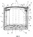
- FIG. 3 is a partial vertical cross-sectional perspective view of the washing machine 1 of the present embodiment.
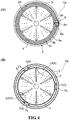
- FIG. 4 is a view of a part of the washing machine 1 observed from top.
- FIG.4(A) is a plan view
- FIG. 4(B) is a transverse sectional view of the dehydration tub 2 of the washing machine 1.
- FIG. 5 is a partial vertical sectional view of the washing machine 1 of the present embodiment.
- the washing machine 1 of the present embodiment includes: a washing machine main body 1a, an outer tub 3 and a dehydration tub 2 constituting a washing tub 1b, a water receiving ring unit 5, a nozzle unit 6, a driving part 40 and a control device (See FIG. 6 ).
- the washing machine body 1a shown in FIG. 1 has a substantially cuboid shape. On the upper surface 10a of the washing machine main body 1a, an opening 11 for throwing in and taking out the laundry into and from the dehydration tub 2 is formed, and an opening and closing a lid 11a capable of opening and closing the opening 11 is attached.
- the outer tub 3 is a bottomed tubular member constituting the profile of the washing tub 1b disposed inside the washing machine main body 1a and is capable of storing the washing water therein. As shown in FIG. 2 , on the outer circumferential surface 3a of the outer tub 3, an acceleration sensor 12 capable of detecting accelerations in horizontal and vertical directions is attached.
- the dehydration tub 2 is disposed coaxially with the outer tub 3 inside the outer tub 3, constitutes a washing tub 1b together with the outer tub 3, and is a bottomed tubular member supported a freely rotatable manner.
- the dehydration tub 2 can accommodate the laundry therein, and has a large number of water-passing holes 2b (see FIG. 3 ) on its wall surface 2a.
- a pulsator (stirring blade) 4 is freely rotatably disposed at the center of the bottom 2c of such a dehydration tub 2.
- the pulsator 4 includes: a substantially disc-shaped pulsator main body 4b, a plurality of upper vane portions 4c formed on the upper surface of the pulsator main body 4b and a plurality of lower vane portions 4a formed on the lower surface of the pulsator main body 4b.
- the pulsator 4 stirs the washing water stored in the outer tub 3 to generate a water flow.
- each baffle plate 7 serves as water-passing pipes, and correspond to the balancers of the present invention.
- Each baffle plate 7 is formed in the following manner: extending in the vertical direction from the bottom 2c to the upper end of the dehydration tub 2, and protruding from the inner circumferential surface 2a1 of the dehydration tub 2 toward the axis S1.
- each baffle plate 7 has a hollow shape, and has a cross-sectional shape of an arc shape.
- the baffle plate as the balancer also has a effect of agitating the laundry during the dehydration process.
- the shape of the baffle plate 7 is configured to slightly protrude toward the axis S1 of the dehydration tub 2 and is widened along the circumferential direction of the dehydration tub 2, so that the accommodating space of the dehydration tub 2 is suppressed from being narrowed.
- an opening portion 71 with an opening in the vicinity of the bottom portion 2c of the dehydration tub 2, more specifically, below the pulsator main body 4b is formed at the lower end portion of such a baffle plate 7.
- a horizontally elongated circulation water inlet 70 is formed at the upper end portion of the baffle plate 7. Therefore, in a washing process in which the drain valve 50a (see FIG. 2 ) is closed and the washing water is stored in the outer tub 3, as shown by the arrow in FIG.
- the washing water stirred by the lower vane portion 4a of the pulsator 4 enters the opening portion 71, overflows the interior of the baffle plate 7 and is discharged from the circulation water inlet 70 so that the clothes are rinsed.
- the washing water circulates in the dehydration tub 2. That is, the baffle plate 7 has a function of circulating the washing water.
- the water-passing pipe portion having the opening portion 71 and the circulation water inlet 70 and capable of performing a shower washing is also suitable for a conventional washing machine, but usually only one water-passing pipe portion is provided.
- a partition piece 7a is configured inside the baffle plate 7, and the partition piece 7a extends from a position between a position where communicating members 5a1, 5b1, 5c1 described below are connected to and the circulation water inlet 70 to a close position the inner circumferential surface 2a1 of the dehydration tub 2.
- the partition piece 7a extends from the upper end edge of the circulation water inlet 70, and the free end 7a1 side of the partition piece 7a curves downward.
- a gap 7b (see FIG. 2 ) is formed between the free end 7a1 of such a partition piece 7a and the inner peripheral surface 2a1 of the dehydration tub 2, and the adjusted water (to be described later) supplied from the water receiving ring unit 5 flows downward through this gap 7b.
- the water receiving ring unit 5 is a device constitutes the water injection device 1c of the present invention, and it is a device formed when annular water guide gutters 5a, 5b, 5c (see FIG.4(A) ) opened upward are overlapped in a three-layer manner toward the axis S1 of the dehydration tub 2 along a radial direction. As shown in FIG. 3 , it is fixed to the upper end portion of the inner circumferential surface 2a1 of the dehydration tub 2.
- the number of water guide gutters 5a, 5b, 5c is set to be the same as the number of baffle plates 7, and a water flow passage through which adjusted water can flow to one of the baffle plates 7 is formed inside.
- Such a water receiving ring unit 5 has substantially the same size and shape as a known liquid balancer attached to a conventional washing machine, and in the present embodiment, it replaces a liquid balancer to be mounted at a mounting position of a general liquid balancer.
- the liquid balancer has a function of passively eliminating the unbalance of the dehydration tub 2 during dehydration, as described later, its effect is small compared with the water receiving ring unit 5 which can actively eliminate the unbalance of the dehydration tub 2.
- Such a water receiving ring unit 5 is connected to the upper end portion of the baffle plate 7 through communicating members 5a1, 5b1 and 5c1.
- the communicating members 5a1, 5b1, 5c1 are connected to the baffle plate 7 above the circulation water inlet 70.
- the nozzle unit 6 is device constituting the water injection device 1c of the present invention, and it also a device that injects the adjusted water individually into such water guide gutters 5a, 5b, 5c.
- the nozzle unit 6 includes three water injection nozzles 6a, 6b, 6c disposed above the water guide gutters 5a, 5b, 5c and water supply valves 26a, 26b, 26c connected to the water injection nozzles 6a, 6b, 6c, 26c.
- the number of the water injection nozzles 6a, 6b, 6c is set to be the same as that of the water guide gutters 5a, 5b, 5c, and they are arranged at positions where the water can be injected into each of the water guide gutters 5a, 5b, 5c.
- tap water is used as the adjusted water.
- a direction switching water supply valve may also be adopted as the water supply valves 26a, 26b, and 26c.
- the water injection device 1c according to the present invention is formed by a receiving ring unit and a nozzle unit.
- the adjusted water injected into the water guide gutters 5a, 5b, 5c of the water receiving ring unit 5 from any one of the water injection nozzles 6a, 6b and 6c of the nozzle unit 6 flows into the baffle plates 7 via the communication members 5a1, 5b1, 5c1.
- the adjusted water flows into the baffle plate 7 from the water guide gutter 5c via the communicating member 5c1.
- the baffle plate 7 may be a pocket baffle structure capable of storing the adjusted water by a centrifugal force. Then, when the dehydration process approaches the end and the rotation speed of the dehydration tub 2 decreases, the centrifugal force in the baffle plate 7 gradually attenuates, the adjusted water flows out of the opening portion 71 by gravity and discharges out of the outer tub 3 via the drain pipe 5. At this time, the adjusted water flows into the lower portion of the pulsator body 4b via the opening portion 71. Therefore, the adjusted water is drained without wetting the clothes located above the pulsator body 4b.
- the driving portion 40 shown in FIG. 2 rotates the pulleys 15 and 15 and the conveyor belt 15b by the motor 10, and rotates the driving shaft 17 extending toward the bottom 2c of the dehydration tub 2 so as to apply the driving force to the dehydration tub 2 and the pulsator 4 to rotate the dehydration tub 2 and the pulsator 4.
- the washing machine 1 mainly rotates the pulsator 4 alone, and in the dehydrating process, the dehydration tub 2 and the pulsator 4 are integrally rotated at a high speed.
- a proximity switch 14 is disposed in the vicinity of one of the pulleys 15, and the passage of a mark 15a formed on the pulley 15 may be detected by the proximity switch 14.
- FIG. 6 is a block diagram showing an electrical structure of the washing machine 1 of the present embodiment.
- the operation of the washing machine 1 is controlled by a control device 30 including a microcomputer.
- the control device 30 includes a central control part (CPU) 31 which governs the control of the entire system, and the control device 30 is connected to a memory 32.
- the memory stores a low-speed rotation set value (N1) required for the rotation control of the dehydration tub 2 before the dehydration operation starts, a high-speed rotation set value (N2) after the start of the dehydration operation, the unbalance amount set value (ma) during low-speed dehydration operation and the unbalance amount set value (mb) during high-speed dehydration operation.
- N1 low-speed rotation set value
- N2 high-speed rotation set value
- ma unbalance amount set value
- mb unbalance amount set value
- the central control part 31 outputs a control signal to a rotation speed control part 33, and further outputs the control signal to a motor control part (motor control circuit) 34 to perform a control of the rotation of the motor 10.
- the rotation speed control part 33 receives a signal indicating the rotation speed of the motor 10 from the motor control part 34 in real time to form a control element.
- An acceleration sensor 12 is connected to an unbalance amount detection part 35, and the acceleration sensor 12 and the proximity switch 14 are connected to an unbalanced position detection part 36.
- the unbalance amount (M) is calculated by an unbalance amount detection part 35 according to the magnitude of the acceleration in the horizontal direction and the vertical direction from the acceleration sensor 12, and the unbalance amount is outputted to an unbalance amount determination part 37.
- an angle of the unbalance direction is calculated by the unbalanced position detection part 36 according to a signal indicating the position of the marker 15a inputted from the proximity switch 14, and an unbalanced position signal is outputted to a water injection control part 38.
- the water injection control part 38 determines whether to supply water to any one of the baffle plates 7 in the dehydration tub 2 and the amount of water to be supplied based on a control program stored in advance. Then, the selected water supply valves 26a, 26b, 26c are opened, and injection of the adjusted water is started. When the unbalance occurs in the dehydration tub 2, the adjusted water is injected into the water guide gutters 5a, 5b, 5c of the water receiving ring unit 5 from the water injection nozzles 6a, 6b, 6c selected based on the calculation of the unbalance amount. When the unbalance is eliminated by the baffle plate 7, the injection of the adjusted water is stopped.
- the water injection control portion 38 carries out a control in a manner of supplying the adjusted water to the baffle plate 7 (A) in the case in which a mass LD (X) of the laundry, which forms a main reason of unbalance, are provided between the baffle plate 7(B) and the baffle plate 7(C) of the dehydration tub 2.
- a mass LD (Y) of the laundry is in the vicinity of the baffle plate 7(A)
- the control is performed so that the adjusted water is supplied to both the baffle plate 7(B) and the baffle plate 7(C).
- the mass LD (Y) of the laundry is located in the vicinity of one of the baffle plates 7, the case in which water injection needs to be performed into the plurality of baffles 7 in order to eliminate the unbalance will be described in details.
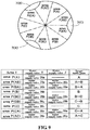
- the central control part 31 shown in FIG. 6 opens a water supply valve X and a water supply valve Z as described in the parameter table of FIG. 9 .
- the determination of the unbalanced position can be divided into two cases: identifying a balancer for eliminating the unbalanced position (i.e. a baffle plate) as one unbalanced position (N) and identifying a balancer for eliminating the unbalanced position as two unbalanced positions (N).
- the area Y of the unbalanced position (N) that identifies one baffle required for eliminating the unbalanced position (N) is the areas P(A), P(B) and P(C).
- the area Y of the unbalanced position (N) required for eliminating the unbalanced position (N) is the areas P(AB), P(BA), P(BC), P(CB), P(CA) and P(AC). It should be noted that, regarding the markings of these six areas, the description order of the portions marking any two of ABC corresponds to the order of the baffle plates to be injected by the water injection device 1c as it is.
- the baffle plate 7 to be injected into the water supply valve X corresponding to the first described character corresponds to the first balancer
- the baffle plate 7 to be injected into the water supply valve Z corresponding to the second character corresponds to the second balancer.
- a balancer that is not described in ABC corresponds to the other balancer, and in the present embodiment, it is the baffle plate 7 closest to the unbalanced position (N).
- the baffle plate 7 corresponding to the first balancer is the baffle plate 7 that is most distant from the unbalanced position (N).
- control method of a washing machine includes : in a dehydration process, an unbalanced position detection step for detecting an unbalanced position (N) of the washing tub 2; a balancer selection step for determining the balancers that requires for water injection (i.e.
- a baffle plate 7 based on the unbalanced position detection step; a first water injection step for injecting the adjusted water into the baffle plates 7 through water supply valves X in a plurality of baffle plates when water injection is required for at least two of the baffle plates 7 in the balancer selection step; an unbalance amount detection step for detecting a transition M in the washing tub 1b during the first water injection step; a water injection switching step for switching the water injection of the adjusted water from the water supply valve X to the water supply valve Y when the unbalance amount detected by the unbalance amount detection step turns into an increase; and a second water injection step for injecting the adjusted water into the baffle plate 7 through the water injection valve Y.
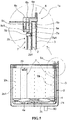
- FIGS. 7 and 8 are flowcharts showing the control of the washing machine 1 of the present embodiment.
- the central control part 31 when the central control part 31 receives an input signal from a dehydration button (not shown) or a signal to start the dehydration process during the operation of the washing procedures, the process proceeds to step SP1, and the dehydration process starts.
- step SP1 the central control part 31 accelerates the rotation of the dehydration tub 2 after the dehydration tub 2 is reversed slowly.
- step SP2 the central control part 31 rotates the dehydration tub 2 at a low speed based on the low-speed rotation set value (N1).
- step SP3 the central control part 31 detects the unbalance amount (M) based on the acceleration value (the x component of the acceleration sensor) given from the acceleration sensor 12.
- step SP4 the central control part 31 compares the unbalance amount (M) with the unbalance amount set value (ma) stored in the memory 32, and determines whether M ⁇ ma holds. When it is determined that M ⁇ ma holds, the process proceeds to step SP6. On the other hand, when it is determined that M ⁇ ma does not hold, the process proceeds to step SP5.
- the unbalance amount set value (ma) is a threshold value indicating that the bias of the laundry is large to the extent that it is difficult to be eliminated even if the adjusted water is supplied to the baffle plate 7. That is, in the case of proceeding to step SP5, it means that it is determined that the bias of the laundry is large to the extent that it is difficult to be eliminated even if the adjusted water is supplied to the baffle plate 7.
- step SP5 after stopping the rotation of the dehydration tub 2, the central control part 31 returns to step SP1 and repeats steps S1 to S4.
- step SP6 when the central control part 31 determines that the elapsed time from the start of the low-speed rotation of the dehydration tub 2 is equal to or greater than the predetermined set time for performing the low-speed rotation processing, the central control part 31 proceeds to step SP7.
- step SP7 the central control part 31 rotates the dehydration tub 2 at a high speed based on the high-speed rotation set value (N2).
- step SP8 the central control part 31 detects the unbalance amount (M) and the unbalanced position (N) based on the acceleration value given from the acceleration sensor 12. That is, step SP8 corresponds to the unbalanced position detecting step according to the present invention.
- step SP9 the central control part 31 compares the unbalance amount (M) with the unbalance amount set value (mb) stored in the memory 32, and determines whether M ⁇ mb holds. When it is determined that M ⁇ mb holds, the process proceeds to step SP23 to be described later. On the other hand, when it is determined that M ⁇ mb does not hold, the process proceeds to step SP10.
- the unbalance amount set value (mb) is a value smaller than the unbalance amount set value (ma), and it is a threshold value indicating that the bias of the laundry is small to the extent that noises cannot be generated even if the adjusted water is not supplied to the baffle plate 7. That is, when it is determined that the eccentric load is small or absent and noises are not generated even if water is not supplied to the baffle plate 7, the process proceeds to step SP23.
- step SP10 based on the unbalanced position (N), the central control part 31 exchanges the water supply valve X, the area Y, and the water supply valve Z shown in FIG. 9 with the values of the parameter table and stores them in, for example, the memory 32. That is, the step SP10 corresponds to a balancer selection step according to the present invention.
- step SP11 the central control part 31 opens the water supply valve X described in the parameter table of FIG. 9 . That is, step SP11 corresponds to the first water injection step according to the present invention.
- step SP12 shown in FIG. 8 the central control part 31 recalculates the unbalance amount (M) based on the acceleration value given from the acceleration sensor 12. That is, step SP12 corresponds to an unbalance amount detection step according to the present invention for detecting the transition of the unbalance amount (M) of the washing tub 1b. It should be noted that, in the step SP12, the unbalance amount (M) commonly shows a gradually reduced trend at the beginning.
- step SP13 the central control part 31 compares the unbalance amount (M) with the unbalance amount set value (mb) stored in the memory 32, and determines whether M ⁇ mb holds. When it is determined that M ⁇ mb holds, the process proceeds to step SP23 to be described later. On the other hand, if it is determined that M ⁇ mb does not hold, the process proceeds to step SP14.
- the unbalance amount set value (mb) is a value smaller than the unbalance amount set value (ma), and it is a threshold value indicating that the bias of the laundry is small to the extent that noises cannot be generated even if the adjusted water is not supplied to the baffle plate 7. In other words, when it is determined that the eccentric load is small or absent and noises are not generated even if water is not supplied to the baffle plate 7, the process proceeds to step SP23.
- step SP14 when the unbalance amount (M) detected in step 12 has not turned to an increase, the central control part 31 proceeds to step SP15.
- step SP16 When it is determined that the unbalance amount (M) has turned to an increase, the process proceeds to step SP16.
- step SP15 when the central control part 31 determines that the elapsed time after the opening of the water supply valve X is equal to or greater than the set time, the process proceeds to step SP16.
- the elapsed time is equal to or smaller than the set time, the process returns to step SP12.
- the set time is, for example, the time it takes for the interior of one baffle plate 7 to be substantially filled with the adjusted water.
- step SP16 the central control part 31 determines which area Y in the areas Y shown in the parameter table of FIG. 9 is the unbalanced position (N) exchanged in the step SP12 and stored in the memory 32.
- the process proceeds to step SP21 to be described later.
- the unbalanced position (N) is the area Y where the water supply valve Z is set, that is, the area P (AB), P (BA), P (BC), P(CB), P(CA) or P(AC)
- the process proceeds to step SP 17.
- step SP 17 the central control part 31 determines whether the water is being injected by the water supply valve X. When the water is being injected by the water supply valve X, the process proceeds to step SP18. When the water is not being injected by the water supply valve X, the process proceeds to step SP19.
- step SP18 the water supply valve X described in the parameter table of FIG. 9 is closed and the water supply valve Z is opened.
- the water supply valve X is a water supply valve 26a corresponding to the baffle plate 7(A)
- the water supply valve Z is the water supply valve 26b corresponding to the baffle plate 7(B) located at a position closer to the area P (AB) than the baffle plate 7 (A) corresponding to the water supply valve 26a, i.e. the second position that is farthest from the area P (AB). That is, the step SP18 corresponds to the second water injection step according to the present invention.
- step SP19 the central control part 31 determines whether water is being injected by the water supply valve Z. When the water is being injected by the water supply valve Z, the process proceeds to step SP20. If the water is not being injected by the water supply valve Z, the process proceeds to step SP21 which will be described later.
- step SP20 the water supply valve Z described in the parameter table of FIG. 9 is closed and other valves are opened.
- the water supply valve Z becomes the water supply valve 26b corresponding to the baffle plate 7(B)
- the other valves are the water supply valves 26c corresponding to the baffle plate 7(C), which is located at a position that is closer to the area P(AB) than the baffle plate 7(B) corresponding to the water supply valve 26c, that is, at a position that is closest to the area P(AB). That is, step SP20 corresponds to other water injection steps.
- step SP21 shown in FIG. 7 the central control part 31 enables all the water supply valves X and Z to be in a closed state.
- step SP22 the central control part 31 stops the rotation of the dehydration tub 2 and then returns to step SP1.
- step SP23 shown in FIG. 7 the central control part 31 enables all the water supply valves X, Z to be in a closed state.
- step SP24 the central control part 31 rotates the dehydration tub 2 at the maximum rotation speed for a predetermined time to perform a dehydration process. Thereafter, the dehydration process is terminated.
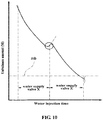
- FIG. 10 the change of a series of eccentricity from the above step SP11 through step SP18 to SP23 is shown.
- the portion indicated by the imaginary line shows the change that the water injection into the baffle plate injected by the water supply valve X exceeds the required amount.
- the step SP14 of detecting the time point at which the unbalance amount (M) rises and switching the water injection valve at the time point it is possible to quickly inject the water into the required baffle plate 7 without increasing additional time for the unbalance amount (M).
- the third water supply valve which has not injected water is opened.
- the water is injected into a plurality of baffle plates 7, the water is injected in order from the baffle plate 7 that is the most distant from the unbalanced position (N) to the baffle plate 7 that is closest to the unbalanced position (N).
- the baffle plate is switched depending on whether the unbalance amount (M) turns into an increase or a predetermined time has elapsed, and when the unbalance amount (M) is smaller than the imbalance amount set value (mb) by a series of water injections, the process is shifted to the operation described below.
- the unbalance amount (M) is not smaller than the imbalance amount set value (mb), that is, when the result in step SP19 is NO, the operation is started again from the beginning of the dehydration process.
- the dehydration tub 2 is accelerated to a high-speed spinning rotation and the dehydration is performed.
- the dehydration is finished and deceleration of the dehydration tub 2 is started and the centrifugal force falls below the gravitational acceleration, the adjusted water in the baffle plate 7 flows downward from the opening 71 and is discharged.
- the washing machine 1 can be designed as follows: the occurrence of vibrations and noises can be prevented and the delay of the operation time can be effectively avoided regardless of the specific stage from the start to the end of the dehydration operation.
- the water injection is switched for the next baffle plate 7.
- the time required for water injection can be made suitable for eliminating the unbalance even if a plurality of balancers needs to be filled with water.
- an excessively long time required for eliminating the unbalance is avoided, and the dehydration process is performed smoothly.
- the unbalance of the dehydration tub 2 in the washing tub 1b is eliminated without slowing or stopping the rotation.
- Generation of vibrations and noises due to the eccentricity of the dehydration tub 2 can be suppressed and a delay in operation time can be effectively avoided.
- the time required for the user's laundry is not delayed, it can contribute to an effective utilization of the user's time and an improvement on the circulation efficiency of the laundromat.
- the first balancer i.e. the baffle plate 7 supplied with water by the water supply valve X
- the baffle plate 7 which is located at a position having a furthest distance from the unbalanced position (N).
- the unbalance amount (M) is promptly reduced by injecting water into the baffle plate 7 which most contributes to the reduction of the unbalance amount (M), and meanwhile, the water is injected for necessary time by the step SP18 which is the water injection switching step, thereby achieving the elimination of the unbalance more rapidly.
- the step SP15 when the increase in the unbalance amount (M) is not detected by the step SP14, the step SP15, that is, the time switching step as described above, is also configured.
- the water injected to the first balancer i.e. the baffle plate 7 in which water is injected from the water supply valve X
- the step SP15 contributes to further eliminate the unbalance.
- the baffle plate 7 for agitating the laundry which was originally mounted on the washing machine 1 is utilized as a balancer, by effectively utilizing the existing configuration, the upsizing of the device is avoided, and the increasing in the number of parts to be manufactured also can be effectively avoided, which also contributes to manufacturing with a higher efficiency.
- the plurality of baffle plates 7 serving as balancers are provided at equal angular intervals on the inner circumferential surface 2a1 of the dehydration tub 2.
- the water receiving ring unit 5 is constituted by three water guide gutters 5a, 5b, 5c, and correspondingly, three baffle plates 7 are provided.
- the present invention is not limited to this, but it just suffices that three or more baffle plates 7 are provided and the number and the configurations of the water guide gutters 5a, 5b, 5c are the same as those of the baffle plates 7.
- the water receiving ring unit 5 may have a configuration in which a plurality of water guide gutters 5a, 5b, 5c is stacked in the vertical direction, so that a horizontal width of the water receiving ring unit 5 is narrowed and the opening of the dehydration tub 2 can be expanded.
- the baffle plate 7 may have a shape that expands upward or downward depending on the operation (situation) of the washing machine 1.
Landscapes
- Engineering & Computer Science (AREA)
- Textile Engineering (AREA)
- Control Of Washing Machine And Dryer (AREA)
- Main Body Construction Of Washing Machines And Laundry Dryers (AREA)
- Detail Structures Of Washing Machines And Dryers (AREA)
Abstract
Description
- The present invention relates to a control method of a washing machine capable of eliminating an unbalance of a washing tub in a dehydration process and suppressing vibrations and noises caused by an eccentricity of the washing tub during dehydration.
- As for ordinary washing machines installed in households or laundromats, vibrations and noises are generated when laundry is biased in a dehydration tub during dehydration. The vibrations and noises may develop into trouble depending on the installation location of the washing machine and the surrounding environment. In addition, when the biasing of the laundry is relatively large, the eccentricity of the washing tub at the time of rotation becomes large, and a large torque is required for rotation, so that the dehydration operation cannot be started.
- In view of this,
Patent Document 1 discloses the following technique: detecting an unbalance amount and an unbalanced position of clothes in a washing tub during dehydration and braking the rotation of the washing tub to lower the centrifugal force when there is unbalance, so that the lumps of the clothes that cause the unbalance fall by gravity and are dispersed. - In addition,
Patent Document 2 discloses the following technique: determining whether there is unbalance in a washing tub during a low-speed rotation, stopping the motor when the unbalance is detected and injecting water into the washing tub to release the lumps of clothes for eliminating the unbalance. - However, in the configuration disclosed in
Patent Document 1, an unbalance detection and a dispersion operation can be performed only when the dehydration tub rotates at a low speed in the dehydration processing, and the unbalance may occur again due to the influence of the type of clothes and the like after the start of the high-speed rotation of the dehydration tub. - Further, in the configurations disclosed in
Patent Documents Patent Document 2, the power consumption is increased, besides, a problem exits that water consumption is also increased. - In the washing machine installed in the laundromat, in particular, the above-described delay in the driving time leads to a decrease in the circulation efficiency of the customer in the store.
-
- Patent Literature 1: Japanese Laid-Open Patent Publication No.
9-290089 - Patent Literature 2: Japanese Laid-Open Patent Publication No.
5650927 - It is an object of the present invention to effectively solve such problems, and it is an object of the present invention to provide a control method of a washing machine to eliminate the unbalance of the washing tub without slowing down or stopping the rotation even if the laundry is unevenly distributed in the dehydration tub during the dehydration operation. Vibrations and noises generated by the eccentricity of the washing tub are suppressed and delays in operation time are effectively avoided.
- The present invention takes the following measures in view of the above problems.
- That is, the control method of the washing machine in the present invention is the control method of the washing machine described below, the washing machine includes: three or more hollow balancers provided with different angular phases around an axis at an inner circumferential surface of a washing tub; and a water injection device for injecting adjusted water into each of the balancers individually. The control method of the washing machine includes: in a dehydration process, an unbalanced position detection step for detecting an unbalanced position of the washing tub; a balancer selection step for determining the balancers that requires for water injection based on the unbalanced position detection step; a first water injection step for injecting the adjusted water into an arbitrary first balancer among a plurality of balancers when water injection is required for at least two of the balancers in the balancer selection step; an unbalance amount detection step for detecting a transition of the unbalance amount of the washing tub during the first water injection step; a water injection switching step for switching the water injection of the adjusted water from the first balancer to a second balancer when the unbalance amount detected by the unbalance amount detection step turns into an increase; and a second water injection step for injecting the adjusted water into the second balancer.
- Further, the first balancer is a balancer that is located at a position having a furthest distance from the unbalanced position.
- Further, the control method of the washing machine includes: a time switching step for switching the water injection of the adjusted water from the first balancer to the second balancer when a predetermined time has elapsed from the first water injection step to the water injection switching step.
- Further, the each of the balancers is a baffle plate protruding from the inner circumferential surface of the washing tub and capable of stirring a laundry.
- Further, the balancers are provided at equal angle intervals along the inner circumferential surface of the washing tub.
- According to the present invention described above, even when water injection is required for a plurality of balancers, the time required for water injection is suitable for eliminating unbalance. Thus, it is possible to prevent the time required for eliminating the unbalance from being too long, and the dehydration process is smoothly performed. That is, according to the present invention, even if the laundry is biased inside the washing tub at the time of the dehydration operation, the unbalance of the washing tub can be eliminated without slowing down or stopping the rotation, the vibrations or noises generated by the eccentricity of the washing tub can be suppressed, and the delay of the operation time can be effectively avoided. As a result, since the time required for washing by a user is not delayed, it is advantageous to the utilization of the user's time and the improvement of the rotation efficiency of the laundromat.
- Further, according to the present invention in which the first balancer is a balancer that is located at a position having a furthest distance from the unbalanced position, the unbalance amount is promptly reduced by injecting water into the balancer that most contributes to the elimination of unbalance, and a necessary time for injecting water is ensured by the water injection switching step, thereby contributing to a quicker elimination of unbalance.
- Further, according to the present invention having such a time switching step, even if the water injection into the first balancer has a low level of unbalance relief, an excessively long time for the water injection is avoided, and it is more advantageous to the elimination of unbalance.
- Further, according to the present invention in which the balancer is a baffle plate capable of agitating the laundry, by effectively utilizing the existing configuration, the upsizing of the device is avoided, and the increasing in the number of parts to be manufactured also can be effectively avoided, which also contributes to manufacturing with a higher efficiency.
- Further, according to the present invention in which the balancers are provided at equiangular intervals, a control from the determination of the unbalanced position to the determination of the balancer requiring water injection is simply performed, so that the elimination of the unbalance can be performed efficiently.
-
-
FIG. 1 is a perspective view showing an appearance of awashing machine 1 according to one embodiment of the present invention; -
FIG. 2 is a schematic diagram showing structures of thesame washing machine 1; -
FIG. 3 is a partial vertical cross-sectional perspective view of thesame washing machine 1; -
FIG. 4 is a view of a part of thesame washing machine 1 observed from top; -
FIG. 5 is a partial vertical sectional view of thesame washing machine 1; -
FIG. 6 is an electrical system block diagram of thesame washing machine 1; -
FIG. 7 is a flowchart showing the flow of control in the dehydration process of thesame washing machine 1; -
FIG. 8 is a flowchart showing the flow of control in the dehydration process of thesame washing machine 1; -
FIG. 9 is a diagram for explaining the flow of control in the dehydration process of thesame washing machine 1; and -
FIG. 10 is a diagram showing a transition of an unbalance amount (M) in the control of thesame washing machine 1. - An embodiment of the present invention will be described in detail below with reference to the drawings.
-
FIG. 1 is a perspective view showing the appearance of a vertical type washing machine (hereinafter referred to as "washing machine") 1 according to one embodiment of the present invention.FIG. 2 is a schematic diagram showing the structures of thewashing machine 1 of the present embodiment.FIG. 3 is a partial vertical cross-sectional perspective view of thewashing machine 1 of the present embodiment.FIG. 4 is a view of a part of thewashing machine 1 observed from top.FIG.4(A) is a plan view, andFIG. 4(B) is a transverse sectional view of thedehydration tub 2 of thewashing machine 1.FIG. 5 is a partial vertical sectional view of thewashing machine 1 of the present embodiment. - The
washing machine 1 of the present embodiment includes: a washing machinemain body 1a, anouter tub 3 and adehydration tub 2 constituting awashing tub 1b, a water receivingring unit 5, anozzle unit 6, a drivingpart 40 and a control device (SeeFIG. 6 ). - The
washing machine body 1a shown inFIG. 1 has a substantially cuboid shape. On theupper surface 10a of the washing machinemain body 1a, anopening 11 for throwing in and taking out the laundry into and from thedehydration tub 2 is formed, and an opening and closing alid 11a capable of opening and closing theopening 11 is attached. - The
outer tub 3 is a bottomed tubular member constituting the profile of thewashing tub 1b disposed inside the washing machinemain body 1a and is capable of storing the washing water therein. As shown inFIG. 2 , on the outercircumferential surface 3a of theouter tub 3, anacceleration sensor 12 capable of detecting accelerations in horizontal and vertical directions is attached. - The
dehydration tub 2 is disposed coaxially with theouter tub 3 inside theouter tub 3, constitutes awashing tub 1b together with theouter tub 3, and is a bottomed tubular member supported a freely rotatable manner. Thedehydration tub 2 can accommodate the laundry therein, and has a large number of water-passingholes 2b (seeFIG. 3 ) on itswall surface 2a. - A pulsator (stirring blade) 4 is freely rotatably disposed at the center of the
bottom 2c of such adehydration tub 2. As shown inFIG. 3 , thepulsator 4 includes: a substantially disc-shaped pulsatormain body 4b, a plurality of upper vane portions 4c formed on the upper surface of the pulsatormain body 4b and a plurality oflower vane portions 4a formed on the lower surface of the pulsatormain body 4b. Thepulsator 4 stirs the washing water stored in theouter tub 3 to generate a water flow. - As shown in
FIGS. 3 and4(B) , on the inner circumferential surface 2al of thedehydration tub 2, three baffle plates(water injection pipe) 7 are provided at equal intervals (equiangular) in the circumferential direction. Thebaffle plates 7 serve as water-passing pipes, and correspond to the balancers of the present invention. Eachbaffle plate 7 is formed in the following manner: extending in the vertical direction from the bottom 2c to the upper end of thedehydration tub 2, and protruding from the inner circumferential surface 2a1 of thedehydration tub 2 toward the axis S1. In addition, eachbaffle plate 7 has a hollow shape, and has a cross-sectional shape of an arc shape. Due to such a shape, the baffle plate as the balancer also has a effect of agitating the laundry during the dehydration process. In this way, the shape of thebaffle plate 7 is configured to slightly protrude toward the axis S1 of thedehydration tub 2 and is widened along the circumferential direction of thedehydration tub 2, so that the accommodating space of thedehydration tub 2 is suppressed from being narrowed. - As shown in
FIGS. 2 and3 , at the lower end portion of such abaffle plate 7, an openingportion 71 with an opening in the vicinity of thebottom portion 2c of thedehydration tub 2, more specifically, below the pulsatormain body 4b is formed. In addition, a horizontally elongatedcirculation water inlet 70 is formed at the upper end portion of thebaffle plate 7. Therefore, in a washing process in which thedrain valve 50a (seeFIG. 2 ) is closed and the washing water is stored in theouter tub 3, as shown by the arrow inFIG. 3 , the washing water stirred by thelower vane portion 4a of thepulsator 4 enters the openingportion 71, overflows the interior of thebaffle plate 7 and is discharged from thecirculation water inlet 70 so that the clothes are rinsed. In addition, by repeating this operation, the washing water circulates in thedehydration tub 2. That is, thebaffle plate 7 has a function of circulating the washing water. It should be noted that, the water-passing pipe portion having the openingportion 71 and thecirculation water inlet 70 and capable of performing a shower washing is also suitable for a conventional washing machine, but usually only one water-passing pipe portion is provided. - Furthermore, a
partition piece 7a is configured inside thebaffle plate 7, and thepartition piece 7a extends from a position between a position where communicating members 5a1, 5b1, 5c1 described below are connected to and thecirculation water inlet 70 to a close position the inner circumferential surface 2a1 of thedehydration tub 2. Thepartition piece 7a extends from the upper end edge of thecirculation water inlet 70, and the free end 7a1 side of thepartition piece 7a curves downward. Agap 7b (seeFIG. 2 ) is formed between the free end 7a1 of such apartition piece 7a and the inner peripheral surface 2a1 of thedehydration tub 2, and the adjusted water (to be described later) supplied from the waterreceiving ring unit 5 flows downward through thisgap 7b. - The water
receiving ring unit 5 is a device constitutes thewater injection device 1c of the present invention, and it is a device formed when annularwater guide gutters FIG.4(A) ) opened upward are overlapped in a three-layer manner toward the axis S1 of thedehydration tub 2 along a radial direction. As shown inFIG. 3 , it is fixed to the upper end portion of the inner circumferential surface 2a1 of thedehydration tub 2. The number ofwater guide gutters baffle plates 7, and a water flow passage through which adjusted water can flow to one of thebaffle plates 7 is formed inside. Such a waterreceiving ring unit 5 has substantially the same size and shape as a known liquid balancer attached to a conventional washing machine, and in the present embodiment, it replaces a liquid balancer to be mounted at a mounting position of a general liquid balancer. Though the liquid balancer has a function of passively eliminating the unbalance of thedehydration tub 2 during dehydration, as described later, its effect is small compared with the waterreceiving ring unit 5 which can actively eliminate the unbalance of thedehydration tub 2. - Such a water
receiving ring unit 5 is connected to the upper end portion of thebaffle plate 7 through communicating members 5a1, 5b1 and 5c1. The communicating members 5a1, 5b1, 5c1 are connected to thebaffle plate 7 above thecirculation water inlet 70. - The
nozzle unit 6 is device constituting thewater injection device 1c of the present invention, and it also a device that injects the adjusted water individually into suchwater guide gutters nozzle unit 6 includes threewater injection nozzles water guide gutters water supply valves water injection nozzles water injection nozzles water guide gutters water guide gutters water supply valves - That is, the
water injection device 1c according to the present invention is formed by a receiving ring unit and a nozzle unit. - With such a configuration of the
water injection device 1c, in the dehydration process in which thedrain valve 50a is opened and the washing water in theouter tub 3 is discharged from thedrain port 50, the adjusted water injected into thewater guide gutters receiving ring unit 5 from any one of thewater injection nozzles nozzle unit 6 flows into thebaffle plates 7 via the communication members 5a1, 5b1, 5c1. For example, when the adjusted water is injected from thewater injection nozzle 6c, as indicated by an arrow inFIG. 5 , the adjusted water flows into thebaffle plate 7 from thewater guide gutter 5c via the communicating member 5c1. When thedehydration tub 2 is in a high-speed rotation state, the adjusted water flowing into thebaffle plate 7 sticks to the inner circumferential surface 2a1 of thedehydration tub 2 by the centrifugal force and stays therein. As a result, the weight of thebaffle plate 7 increases and the balance of thedehydration tub 2 changes. In this way, thebaffle plate 7 may be a pocket baffle structure capable of storing the adjusted water by a centrifugal force. Then, when the dehydration process approaches the end and the rotation speed of thedehydration tub 2 decreases, the centrifugal force in thebaffle plate 7 gradually attenuates, the adjusted water flows out of the openingportion 71 by gravity and discharges out of theouter tub 3 via thedrain pipe 5. At this time, the adjusted water flows into the lower portion of thepulsator body 4b via the openingportion 71. Therefore, the adjusted water is drained without wetting the clothes located above thepulsator body 4b. - The driving
portion 40 shown inFIG. 2 rotates thepulleys conveyor belt 15b by themotor 10, and rotates the drivingshaft 17 extending toward the bottom 2c of thedehydration tub 2 so as to apply the driving force to thedehydration tub 2 and thepulsator 4 to rotate thedehydration tub 2 and thepulsator 4. In the washing process, thewashing machine 1 mainly rotates thepulsator 4 alone, and in the dehydrating process, thedehydration tub 2 and thepulsator 4 are integrally rotated at a high speed. Aproximity switch 14 is disposed in the vicinity of one of thepulleys 15, and the passage of amark 15a formed on thepulley 15 may be detected by theproximity switch 14. -
FIG. 6 is a block diagram showing an electrical structure of thewashing machine 1 of the present embodiment. The operation of thewashing machine 1 is controlled by acontrol device 30 including a microcomputer. Thecontrol device 30 includes a central control part (CPU) 31 which governs the control of the entire system, and thecontrol device 30 is connected to a memory 32.The memory stores a low-speed rotation set value (N1) required for the rotation control of thedehydration tub 2 before the dehydration operation starts, a high-speed rotation set value (N2) after the start of the dehydration operation, the unbalance amount set value (ma) during low-speed dehydration operation and the unbalance amount set value (mb) during high-speed dehydration operation. In addition, when the program stored in thememory 32 is executed by the microcomputer to carry out a predetermined operation, data etc. to be actually used for executing the above-mentioned program temporarily stored in thememory 32 by thecontrol device 30. - The
central control part 31 outputs a control signal to a rotationspeed control part 33, and further outputs the control signal to a motor control part (motor control circuit) 34 to perform a control of the rotation of themotor 10. It should be noted that, the rotationspeed control part 33 receives a signal indicating the rotation speed of themotor 10 from themotor control part 34 in real time to form a control element. Anacceleration sensor 12 is connected to an unbalanceamount detection part 35, and theacceleration sensor 12 and theproximity switch 14 are connected to an unbalancedposition detection part 36. - Therefore, when the
proximity switch 14 detects themarker 15a (SeeFIG. 2 ), the unbalance amount (M) is calculated by an unbalanceamount detection part 35 according to the magnitude of the acceleration in the horizontal direction and the vertical direction from theacceleration sensor 12, and the unbalance amount is outputted to an unbalanceamount determination part 37. On the other hand, an angle of the unbalance direction is calculated by the unbalancedposition detection part 36 according to a signal indicating the position of themarker 15a inputted from theproximity switch 14, and an unbalanced position signal is outputted to a waterinjection control part 38. - Upon receiving the unbalance amount from the unbalance
amount determination part 37 and the signal indicating the unbalanced position from the unbalancedposition detection part 36, the waterinjection control part 38 determines whether to supply water to any one of thebaffle plates 7 in thedehydration tub 2 and the amount of water to be supplied based on a control program stored in advance. Then, the selectedwater supply valves dehydration tub 2, the adjusted water is injected into thewater guide gutters receiving ring unit 5 from thewater injection nozzles baffle plate 7, the injection of the adjusted water is stopped. - It should be noted that, for example, as shown in
FIG. 4(B) , the waterinjection control portion 38 carries out a control in a manner of supplying the adjusted water to the baffle plate 7 (A) in the case in which a mass LD (X) of the laundry, which forms a main reason of unbalance, are provided between the baffle plate 7(B) and the baffle plate 7(C) of thedehydration tub 2. In addition, when a mass LD (Y) of the laundry is in the vicinity of the baffle plate 7(A), the control is performed so that the adjusted water is supplied to both the baffle plate 7(B) and the baffle plate 7(C). - Here, in the present embodiment, for the above-mentioned case that the mass LD (Y) of the laundry is located in the vicinity of one of the
baffle plates 7, the case in which water injection needs to be performed into the plurality ofbaffles 7 in order to eliminate the unbalance will be described in details. - That is, the
central control part 31 shown inFIG. 6 opens a water supply valve X and a water supply valve Z as described in the parameter table ofFIG. 9 . Here, in the present embodiment, by dividing into nine items as shown inFIG. 9 , the determination of the unbalanced position can be divided into two cases: identifying a balancer for eliminating the unbalanced position (i.e. a baffle plate) as one unbalanced position (N) and identifying a balancer for eliminating the unbalanced position as two unbalanced positions (N). - That is, the area Y of the unbalanced position (N) that identifies one baffle required for eliminating the unbalanced position (N) is the areas P(A), P(B) and P(C). In addition, the area Y of the unbalanced position (N) required for eliminating the unbalanced position (N) is the areas P(AB), P(BA), P(BC), P(CB), P(CA) and P(AC). It should be noted that, regarding the markings of these six areas, the description order of the portions marking any two of ABC corresponds to the order of the baffle plates to be injected by the
water injection device 1c as it is. - That is, among the characters of ABC written in these six areas, the
baffle plate 7 to be injected into the water supply valve X corresponding to the first described character corresponds to the first balancer, and thebaffle plate 7 to be injected into the water supply valve Z corresponding to the second character corresponds to the second balancer. - In addition, a balancer that is not described in ABC corresponds to the other balancer, and in the present embodiment, it is the
baffle plate 7 closest to the unbalanced position (N). - In other words, the
baffle plate 7 corresponding to the first balancer is thebaffle plate 7 that is most distant from the unbalanced position (N). - Here, the control method of a washing machine according to the present embodiment includes : in a dehydration process, an unbalanced position detection step for detecting an unbalanced position (N) of the
washing tub 2; a balancer selection step for determining the balancers that requires for water injection (i.e. a baffle plate 7) based on the unbalanced position detection step; a first water injection step for injecting the adjusted water into thebaffle plates 7 through water supply valves X in a plurality of baffle plates when water injection is required for at least two of thebaffle plates 7 in the balancer selection step; an unbalance amount detection step for detecting a transition M in thewashing tub 1b during the first water injection step; a water injection switching step for switching the water injection of the adjusted water from the water supply valve X to the water supply valve Y when the unbalance amount detected by the unbalance amount detection step turns into an increase; and a second water injection step for injecting the adjusted water into thebaffle plate 7 through the water injection valve Y. -
FIGS. 7 and8 are flowcharts showing the control of thewashing machine 1 of the present embodiment. - In the present embodiment, when the
central control part 31 receives an input signal from a dehydration button (not shown) or a signal to start the dehydration process during the operation of the washing procedures, the process proceeds to step SP1, and the dehydration process starts. - In step SP1, the
central control part 31 accelerates the rotation of thedehydration tub 2 after thedehydration tub 2 is reversed slowly. - In step SP2, the
central control part 31 rotates thedehydration tub 2 at a low speed based on the low-speed rotation set value (N1). - In step SP3, the
central control part 31 detects the unbalance amount (M) based on the acceleration value (the x component of the acceleration sensor) given from theacceleration sensor 12. - In step SP4, the
central control part 31 compares the unbalance amount (M) with the unbalance amount set value (ma) stored in thememory 32, and determines whether M<ma holds. When it is determined that M<ma holds, the process proceeds to step SP6. On the other hand, when it is determined that M<ma does not hold, the process proceeds to step SP5. Here, the unbalance amount set value (ma) is a threshold value indicating that the bias of the laundry is large to the extent that it is difficult to be eliminated even if the adjusted water is supplied to thebaffle plate 7. That is, in the case of proceeding to step SP5, it means that it is determined that the bias of the laundry is large to the extent that it is difficult to be eliminated even if the adjusted water is supplied to thebaffle plate 7. - In step SP5, after stopping the rotation of the
dehydration tub 2, thecentral control part 31 returns to step SP1 and repeats steps S1 to S4. - In step SP6, when the
central control part 31 determines that the elapsed time from the start of the low-speed rotation of thedehydration tub 2 is equal to or greater than the predetermined set time for performing the low-speed rotation processing, thecentral control part 31 proceeds to step SP7. - In step SP7, the
central control part 31 rotates thedehydration tub 2 at a high speed based on the high-speed rotation set value (N2). - In step SP8, the
central control part 31 detects the unbalance amount (M) and the unbalanced position (N) based on the acceleration value given from theacceleration sensor 12. That is, step SP8 corresponds to the unbalanced position detecting step according to the present invention. - In step SP9, the
central control part 31 compares the unbalance amount (M) with the unbalance amount set value (mb) stored in thememory 32, and determines whether M<mb holds. When it is determined that M<mb holds, the process proceeds to step SP23 to be described later. On the other hand, when it is determined that M<mb does not hold, the process proceeds to step SP10. Here, the unbalance amount set value (mb) is a value smaller than the unbalance amount set value (ma), and it is a threshold value indicating that the bias of the laundry is small to the extent that noises cannot be generated even if the adjusted water is not supplied to thebaffle plate 7. That is, when it is determined that the eccentric load is small or absent and noises are not generated even if water is not supplied to thebaffle plate 7, the process proceeds to step SP23. - In step SP10, based on the unbalanced position (N), the
central control part 31 exchanges the water supply valve X, the area Y, and the water supply valve Z shown inFIG. 9 with the values of the parameter table and stores them in, for example, thememory 32. That is, the step SP10 corresponds to a balancer selection step according to the present invention. - In step SP11, the
central control part 31 opens the water supply valve X described in the parameter table ofFIG. 9 . That is, step SP11 corresponds to the first water injection step according to the present invention. - In step SP12 shown in
FIG. 8 , thecentral control part 31 recalculates the unbalance amount (M) based on the acceleration value given from theacceleration sensor 12. That is, step SP12 corresponds to an unbalance amount detection step according to the present invention for detecting the transition of the unbalance amount (M) of thewashing tub 1b. It should be noted that, in the step SP12, the unbalance amount (M) commonly shows a gradually reduced trend at the beginning. - In step SP13, the
central control part 31 compares the unbalance amount (M) with the unbalance amount set value (mb) stored in thememory 32, and determines whether M<mb holds. When it is determined that M<mb holds, the process proceeds to step SP23 to be described later. On the other hand, if it is determined that M<mb does not hold, the process proceeds to step SP14. Here, the unbalance amount set value (mb) is a value smaller than the unbalance amount set value (ma), and it is a threshold value indicating that the bias of the laundry is small to the extent that noises cannot be generated even if the adjusted water is not supplied to thebaffle plate 7. In other words, when it is determined that the eccentric load is small or absent and noises are not generated even if water is not supplied to thebaffle plate 7, the process proceeds to step SP23. - In step SP14, when the unbalance amount (M) detected in
step 12 has not turned to an increase, thecentral control part 31 proceeds to step SP15. When it is determined that the unbalance amount (M) has turned to an increase, the process proceeds to step SP16. - In step SP15, when the
central control part 31 determines that the elapsed time after the opening of the water supply valve X is equal to or greater than the set time, the process proceeds to step SP16. When the elapsed time is equal to or smaller than the set time, the process returns to step SP12. Here, the set time is, for example, the time it takes for the interior of onebaffle plate 7 to be substantially filled with the adjusted water. - In step SP16, the
central control part 31 determines which area Y in the areas Y shown in the parameter table ofFIG. 9 is the unbalanced position (N) exchanged in the step SP12 and stored in thememory 32. When it is determined that the unbalanced position (N) is the area Y where the water supply valve Z is not set, that is, the area P(A), P(B) or P(C), the process proceeds to step SP21 to be described later. When it is determined that the unbalanced position (N) is the area Y where the water supply valve Z is set, that is, the area P (AB), P (BA), P (BC), P(CB), P(CA) or P(AC), the process proceeds to stepSP 17. - In
step SP 17, thecentral control part 31 determines whether the water is being injected by the water supply valve X. When the water is being injected by the water supply valve X, the process proceeds to step SP18. When the water is not being injected by the water supply valve X, the process proceeds to step SP19. - In step SP18, the water supply valve X described in the parameter table of
FIG. 9 is closed and the water supply valve Z is opened. For example, when the initial unbalanced position (N) is the area P(AB), the water supply valve X is awater supply valve 26a corresponding to the baffle plate 7(A), and the water supply valve Z is thewater supply valve 26b corresponding to the baffle plate 7(B) located at a position closer to the area P (AB) than the baffle plate 7 (A) corresponding to thewater supply valve 26a, i.e. the second position that is farthest from the area P (AB). That is, the step SP18 corresponds to the second water injection step according to the present invention. - In step SP19, the
central control part 31 determines whether water is being injected by the water supply valve Z. When the water is being injected by the water supply valve Z, the process proceeds to step SP20. If the water is not being injected by the water supply valve Z, the process proceeds to step SP21 which will be described later. - In step SP20, the water supply valve Z described in the parameter table of
FIG. 9 is closed and other valves are opened. For example, when the initial unbalanced position (N) is the area P(AB), the water supply valve Z becomes thewater supply valve 26b corresponding to the baffle plate 7(B), and the other valves are thewater supply valves 26c corresponding to the baffle plate 7(C), which is located at a position that is closer to the area P(AB) than the baffle plate 7(B) corresponding to thewater supply valve 26c, that is, at a position that is closest to the area P(AB). That is, step SP20 corresponds to other water injection steps. - In step SP21 shown in
FIG. 7 , thecentral control part 31 enables all the water supply valves X and Z to be in a closed state. - In step SP22, the
central control part 31 stops the rotation of thedehydration tub 2 and then returns to step SP1. - In such way, when it is determined that the unbalanced load is so large as not to be eliminated by the water supply to the
baffle plate 7, the processes of steps SP21 and SP22 are performed and the dehydration process is restarted from the beginning. - In step SP23 shown in
FIG. 7 , thecentral control part 31 enables all the water supply valves X, Z to be in a closed state. - In step SP24, the
central control part 31 rotates thedehydration tub 2 at the maximum rotation speed for a predetermined time to perform a dehydration process. Thereafter, the dehydration process is terminated. - In addition, in
FIG. 10 , the change of a series of eccentricity from the above step SP11 through step SP18 to SP23 is shown. In this way, first, regarding the curve indicating the eccentricity, i.e. the unbalance amount (M), the portion indicated by the imaginary line shows the change that the water injection into the baffle plate injected by the water supply valve X exceeds the required amount. In the present embodiment, by providing the step SP14 of detecting the time point at which the unbalance amount (M) rises and switching the water injection valve at the time point, it is possible to quickly inject the water into the requiredbaffle plate 7 without increasing additional time for the unbalance amount (M). - In addition, in the present embodiment, in the case in which the unbalance amount (M) still is not smaller than an unbalance amount set value (mb) at the time of carrying out a water injection (corresponding to injecting water to the second balancer) by the water supply valve Z, the third water supply valve which has not injected water is opened. As described above, in this embodiment, when the water is injected into a plurality of
baffle plates 7, the water is injected in order from thebaffle plate 7 that is the most distant from the unbalanced position (N) to thebaffle plate 7 that is closest to the unbalanced position (N). Then, the baffle plate is switched depending on whether the unbalance amount (M) turns into an increase or a predetermined time has elapsed, and when the unbalance amount (M) is smaller than the imbalance amount set value (mb) by a series of water injections, the process is shifted to the operation described below. When the unbalance amount (M) is not smaller than the imbalance amount set value (mb), that is, when the result in step SP19 is NO, the operation is started again from the beginning of the dehydration process. - Thereafter, when the unbalance amount (M) becomes equal to or smaller than the set value, the
dehydration tub 2 is accelerated to a high-speed spinning rotation and the dehydration is performed. When the dehydration is finished and deceleration of thedehydration tub 2 is started and the centrifugal force falls below the gravitational acceleration, the adjusted water in thebaffle plate 7 flows downward from theopening 71 and is discharged. - According to the flow of the dehydration process by the above control method, even if the water injection is required for a plurality of
baffle plates 7, the unbalance state is eliminated promptly and easily. Therefore, thewashing machine 1 can be designed as follows: the occurrence of vibrations and noises can be prevented and the delay of the operation time can be effectively avoided regardless of the specific stage from the start to the end of the dehydration operation. - As described above, for the control method of the
washing machine 1 of the present invention, at the time point of step SP14 that the unbalance amount (M) rises during the water injection into thebaffle plate 7 that performs the water injection first, the water injection is switched for thenext baffle plate 7. By performing above control, the time required for water injection can be made suitable for eliminating the unbalance even if a plurality of balancers needs to be filled with water. In particular, it effectively avoids unnecessary increase in the time for water injection into thebaffle plate 7 that serves as the first balancer. As a result, an excessively long time required for eliminating the unbalance is avoided, and the dehydration process is performed smoothly. - That is, according to the present embodiment, even if the uneven distribution of laundry in the
dehydration tub 2 occurs in the dehydration process, the unbalance of thedehydration tub 2 in thewashing tub 1b is eliminated without slowing or stopping the rotation. Generation of vibrations and noises due to the eccentricity of thedehydration tub 2 can be suppressed and a delay in operation time can be effectively avoided. As a result, since the time required for the user's laundry is not delayed, it can contribute to an effective utilization of the user's time and an improvement on the circulation efficiency of the laundromat. - In addition, the first balancer, i.e. the
baffle plate 7 supplied with water by the water supply valve X, is thebaffle plate 7 which is located at a position having a furthest distance from the unbalanced position (N). Thus, the unbalance amount (M) is promptly reduced by injecting water into thebaffle plate 7 which most contributes to the reduction of the unbalance amount (M), and meanwhile, the water is injected for necessary time by the step SP18 which is the water injection switching step, thereby achieving the elimination of the unbalance more rapidly. - Further, in the present embodiment, when the increase in the unbalance amount (M) is not detected by the step SP14, the step SP15, that is, the time switching step as described above, is also configured. Thus, even if the water injected to the first balancer (i.e. the
baffle plate 7 in which water is injected from the water supply valve X) have a low degree of actual eliminating the unbalance, an excessively long time for the water injection is avoided, and it contributes to further eliminate the unbalance. - Further, in the present embodiment, since the
baffle plate 7 for agitating the laundry which was originally mounted on thewashing machine 1 is utilized as a balancer, by effectively utilizing the existing configuration, the upsizing of the device is avoided, and the increasing in the number of parts to be manufactured also can be effectively avoided, which also contributes to manufacturing with a higher efficiency. - In addition, in the present embodiment, the plurality of
baffle plates 7 serving as balancers are provided at equal angular intervals on the inner circumferential surface 2a1 of thedehydration tub 2. Thus, a control from the determination of unbalanced position (N) to the determination of the water supply valve X is simplified, and the efficient elimination of the unbalance is achieved at the same time. - Although one embodiment of the present invention has been described above, the configuration of the present embodiment is not limited to the one described above, and various modifications are possible.
- For example, in the above-described embodiment, an example in which the present invention is applied to a so-called vertical type fully automatic washing machine as a washing machine has been disclosed, but, the control method according to the present invention undoubtedly can be used for a home-use diagonal drum-type fully automatic washing machine and can be widely applied to a horizontal type washer-dryer in a store of a laundromat.
- Further, for example, in the above embodiment, the water
receiving ring unit 5 is constituted by threewater guide gutters baffle plates 7 are provided. However, the present invention is not limited to this, but it just suffices that three ormore baffle plates 7 are provided and the number and the configurations of thewater guide gutters baffle plates 7. - Further, the water
receiving ring unit 5 may have a configuration in which a plurality ofwater guide gutters receiving ring unit 5 is narrowed and the opening of thedehydration tub 2 can be expanded. - Further, the
baffle plate 7 may have a shape that expands upward or downward depending on the operation (situation) of thewashing machine 1. - Other configurations can be modified in various ways without departing from the spirit of the present invention.
- 1: Washing machine; 1b: Washing tub; 1c: Water injection device; 2al: Inner peripheral surface (of a dehydration tub); 7: Balancer (baffle plate); S1: Axis; SP8: Unbalanced position detection step; SP10: Balancer selection step; SP11: First water injection step; SP14, SP16, SP17, SP18: Water injection switching step; SP15, SP16, SP17, SP18: Time switching step; SP18: Second water injection step
Claims (5)
- A control method of a washing machine, wherein the washing machine comprises:three or more hollow balancers provided with different angular phases around an axis at an inner circumferential surface of a washing tub; anda water injection device for injecting adjusted water into each of the balancers individually,wherein the control method of the washing machine comprises:in a dehydration process,an unbalanced position detection step for detecting an unbalanced position of the washing tub;a balancer selection step for determining the balancers that requires for water injection based on the unbalanced position detection step;a first water injection step for injecting the adjusted water into an arbitrary first balancer among a plurality of balancers when water injection is required for at least two of the balancers in the balancer selection step;an unbalance amount detection step for detecting a transition of the unbalance amount of the washing tub during the first water injection step;a water injection switching step for switching the water injection of the adjusted water from the first balancer to a second balancer when the unbalance amount detected by the unbalance amount detection step turns into an increase; anda second water injection step for injecting the adjusted water into the second balancer.
- The control method of the washing machine according to claim 1, wherein the first balancer is a balancer that is located at a position having a furthest distance from the unbalanced position.
- The control method of the washing machine according to claim 1 or claim 2, comprising:a time switching step for switching the water injection of the adjusted water from the first balancer to the second balancer when a predetermined time has elapsed from the first water injection step to the water injection switching step.
- The control method of the washing machine according to claim 1 or claim 2, wherein the each of the balancers is a baffle plate protruding from the inner circumferential surface of the washing tub and capable of stirring a laundry.
- The control method of the washing machine according to claim 1 or claim 2, wherein the balancers are provided at equal angle intervals along the inner circumferential surface of the washing tub.
Applications Claiming Priority (2)
| Application Number | Priority Date | Filing Date | Title |
|---|---|---|---|
| JP2015251163A JP2017113232A (en) | 2015-12-24 | 2015-12-24 | Washing machine control method |
| PCT/CN2016/111802 WO2017107989A1 (en) | 2015-12-24 | 2016-12-23 | Method of controlling washing machine |
Publications (3)
| Publication Number | Publication Date |
|---|---|
| EP3396043A1 true EP3396043A1 (en) | 2018-10-31 |
| EP3396043A4 EP3396043A4 (en) | 2019-01-09 |
| EP3396043B1 EP3396043B1 (en) | 2021-05-19 |
Family
ID=59089174
Family Applications (1)
| Application Number | Title | Priority Date | Filing Date |
|---|---|---|---|
| EP16877799.3A Active EP3396043B1 (en) | 2015-12-24 | 2016-12-23 | Method of controlling a washing machine |
Country Status (5)
| Country | Link |
|---|---|
| US (1) | US10619285B2 (en) |
| EP (1) | EP3396043B1 (en) |
| JP (1) | JP2017113232A (en) |
| CN (1) | CN108431320B (en) |
| WO (1) | WO2017107989A1 (en) |
Families Citing this family (13)
| Publication number | Priority date | Publication date | Assignee | Title |
|---|---|---|---|---|
| JP7100839B2 (en) * | 2017-11-21 | 2022-07-14 | 青島海爾洗衣机有限公司 | Drum type washing machine |
| CN113005716B (en) * | 2019-12-18 | 2023-01-17 | 广东美的白色家电技术创新中心有限公司 | Washing device, control method thereof, and readable storage medium |
| KR102824479B1 (en) * | 2019-12-20 | 2025-06-24 | 엘지전자 주식회사 | Controlling Method of Laundry Treatment Apparatus |
| JP7503266B2 (en) * | 2020-06-29 | 2024-06-20 | 青島海爾洗衣机有限公司 | washing machine |
| JP7527560B2 (en) * | 2020-06-29 | 2024-08-05 | 青島海爾洗衣机有限公司 | washing machine |
| JP7482479B2 (en) * | 2020-06-29 | 2024-05-14 | 青島海爾洗衣机有限公司 | washing machine |
| CN114318777B (en) * | 2020-09-30 | 2023-02-17 | 无锡小天鹅电器有限公司 | Balancing device, barrel assembly and clothes treatment equipment |
| CN114318767B (en) * | 2020-09-30 | 2023-02-24 | 无锡小天鹅电器有限公司 | Clothes treatment equipment and control method thereof |
| JP7556816B2 (en) * | 2021-04-02 | 2024-09-26 | 東芝ライフスタイル株式会社 | washing machine |
| JP7589917B2 (en) * | 2021-04-26 | 2024-11-26 | 青島海爾洗衣机有限公司 | washing machine |
| JP2023035692A (en) * | 2021-09-01 | 2023-03-13 | 青島海爾洗衣机有限公司 | washing machine |
| JP2023035691A (en) * | 2021-09-01 | 2023-03-13 | 青島海爾洗衣机有限公司 | washing machine |
| CN117298712B (en) * | 2023-10-27 | 2024-07-26 | 深圳市汉斯顿净水设备有限公司 | Rotary filter element capable of keeping high rotation speed stability |
Family Cites Families (22)
| Publication number | Priority date | Publication date | Assignee | Title |
|---|---|---|---|---|
| US2534269A (en) * | 1948-05-26 | 1950-12-19 | Kahn | Automatic balancing system for cleaning machine cylinders |
| US3610069A (en) * | 1969-11-14 | 1971-10-05 | Arundale Mfg Inc | Molded one-piece balancing ring |
| US5280660A (en) * | 1992-10-05 | 1994-01-25 | Pellerin Milnor Corporation | Centrifugal extracting machine having balancing system |
| JP2954031B2 (en) * | 1995-08-28 | 1999-09-27 | 三星電子株式会社 | Washing machine balance |
| JP3332769B2 (en) | 1996-02-27 | 2002-10-07 | 三洋電機株式会社 | Centrifugal dewatering device |
| JP2901913B2 (en) * | 1996-03-12 | 1999-06-07 | 株式会社東芝 | Dewatering tank balancer |
| JPH1024186A (en) | 1996-07-10 | 1998-01-27 | Sanyo Electric Co Ltd | Drum type washing machine |
| JP3188209B2 (en) | 1997-03-21 | 2001-07-16 | 三洋電機株式会社 | Centrifugal dehydrator |
| US5829084A (en) * | 1997-06-02 | 1998-11-03 | Fujiwara; Leslie H. | Method and system for balancing an upright washing machine |
| JP2001062185A (en) | 1999-08-30 | 2001-03-13 | Sanyo Electric Co Ltd | Drum type washing machine |
| PL1736589T3 (en) * | 2005-06-24 | 2015-03-31 | V Zug Ag | Washing machine with unbalance detector |
| US8695381B2 (en) * | 2008-03-28 | 2014-04-15 | Electrolux Home Products, Inc. | Laundering device vibration control |
| KR20110057302A (en) * | 2009-11-24 | 2011-06-01 | 삼성전자주식회사 | Fluid balancer and washing machine with it |
| KR101370421B1 (en) | 2009-12-31 | 2014-03-25 | 아세릭 에이. 에스 | A washing machine wherein the unbalanced load is balanced |
| JP5650927B2 (en) | 2010-05-20 | 2015-01-07 | ハイアール グループ コーポレーション | Washing machine |
| WO2011144559A1 (en) * | 2010-05-20 | 2011-11-24 | Arcelik Anonim Sirketi | A washing machine wherein the unbalanced load is balanced |
| US9003838B2 (en) * | 2010-12-08 | 2015-04-14 | Whirlpool Corporation | Laundry treating appliance with balancing system |
| US8713977B2 (en) * | 2010-12-08 | 2014-05-06 | Whirlpool Corporation | Laundry treating appliance with balancing system |
| US8991223B2 (en) * | 2010-12-08 | 2015-03-31 | Whirlpool Corporation | Laundry treating appliance with balancing system |
| CN102560965B (en) | 2012-01-17 | 2014-02-05 | 江苏海狮机械集团有限公司 | Roller balancing device for full-automatic washer extractor |
| KR102032845B1 (en) | 2013-02-13 | 2019-10-16 | 엘지전자 주식회사 | Laundry Treating Apparatus |
| JP6608659B2 (en) * | 2015-09-17 | 2019-11-20 | 青島海爾洗衣机有限公司 | Washing machine and control method of washing machine |
-
2015
- 2015-12-24 JP JP2015251163A patent/JP2017113232A/en active Pending
-
2016
- 2016-12-23 US US16/065,786 patent/US10619285B2/en active Active
- 2016-12-23 EP EP16877799.3A patent/EP3396043B1/en active Active
- 2016-12-23 WO PCT/CN2016/111802 patent/WO2017107989A1/en not_active Ceased
- 2016-12-23 CN CN201680075501.3A patent/CN108431320B/en active Active
Also Published As
| Publication number | Publication date |
|---|---|
| WO2017107989A1 (en) | 2017-06-29 |
| US20190003100A1 (en) | 2019-01-03 |
| JP2017113232A (en) | 2017-06-29 |
| CN108431320A (en) | 2018-08-21 |
| EP3396043A4 (en) | 2019-01-09 |
| US10619285B2 (en) | 2020-04-14 |
| CN108431320B (en) | 2021-03-02 |
| EP3396043B1 (en) | 2021-05-19 |
Similar Documents
| Publication | Publication Date | Title |
|---|---|---|
| EP3396043B1 (en) | Method of controlling a washing machine | |
| JP6608659B2 (en) | Washing machine and control method of washing machine | |
| CN105839336B (en) | The control method of washing machine | |
| CN104862920B (en) | Washing machine with ball balancer and the method for controlling its vibration | |
| JP6736807B2 (en) | Washing machine | |
| US9187856B2 (en) | Washing machine and washing method | |
| CN114729489B (en) | Washing machine | |
| JP7093069B2 (en) | washing machine | |
| JP7369398B2 (en) | washing machine | |
| JP7527560B2 (en) | washing machine | |
| KR20220021710A (en) | Clothes Treating Apparatus and Controlling Method thereof | |
| KR100673708B1 (en) | How to dehydrate laundry | |
| JP7503266B2 (en) | washing machine | |
| KR20230172686A (en) | Washing apparutus and controlling method thereof | |
| KR20120109171A (en) | Method for controlling dehydration in drum type washing machine | |
| KR20120109172A (en) | Method for controlling dehydration in drum type washing machine | |
| WO2007064052A1 (en) | Control process of dehydration in drum type washing machine | |
| AU2006202729B1 (en) | Improved lower torus for a washing machine | |
| KR20110013156A (en) | Control method of laundry treatment equipment |
Legal Events
| Date | Code | Title | Description |
|---|---|---|---|
| STAA | Information on the status of an ep patent application or granted ep patent |
Free format text: STATUS: THE INTERNATIONAL PUBLICATION HAS BEEN MADE |
|
| PUAI | Public reference made under article 153(3) epc to a published international application that has entered the european phase |
Free format text: ORIGINAL CODE: 0009012 |
|
| STAA | Information on the status of an ep patent application or granted ep patent |
Free format text: STATUS: REQUEST FOR EXAMINATION WAS MADE |
|
| 17P | Request for examination filed |
Effective date: 20180704 |
|
| AK | Designated contracting states |
Kind code of ref document: A1 Designated state(s): AL AT BE BG CH CY CZ DE DK EE ES FI FR GB GR HR HU IE IS IT LI LT LU LV MC MK MT NL NO PL PT RO RS SE SI SK SM TR |
|
| AX | Request for extension of the european patent |
Extension state: BA ME |
|
| A4 | Supplementary search report drawn up and despatched |
Effective date: 20181210 |
|
| RIC1 | Information provided on ipc code assigned before grant |
Ipc: D06F 33/02 20060101AFI20181204BHEP Ipc: D06F 37/24 20060101ALN20181204BHEP Ipc: D06F 37/14 20060101ALN20181204BHEP |
|
| DAV | Request for validation of the european patent (deleted) | ||
| DAX | Request for extension of the european patent (deleted) | ||
| STAA | Information on the status of an ep patent application or granted ep patent |
Free format text: STATUS: EXAMINATION IS IN PROGRESS |
|
| 17Q | First examination report despatched |
Effective date: 20200630 |
|
| REG | Reference to a national code |
Ref country code: DE Ref legal event code: R079 Ref document number: 602016058237 Country of ref document: DE Free format text: PREVIOUS MAIN CLASS: D06F0033020000 Ipc: D06F0033480000 |
|
| GRAP | Despatch of communication of intention to grant a patent |
Free format text: ORIGINAL CODE: EPIDOSNIGR1 |
|
| STAA | Information on the status of an ep patent application or granted ep patent |
Free format text: STATUS: GRANT OF PATENT IS INTENDED |
|
| RIC1 | Information provided on ipc code assigned before grant |
Ipc: D06F 37/24 20060101ALI20210201BHEP Ipc: D06F 105/00 20200101ALN20210201BHEP Ipc: D06F 33/48 20200101AFI20210201BHEP Ipc: D06F 37/14 20060101ALN20210201BHEP Ipc: D06F 103/26 20200101ALN20210201BHEP Ipc: D06F 105/02 20200101ALN20210201BHEP |
|
| INTG | Intention to grant announced |
Effective date: 20210305 |
|
| GRAS | Grant fee paid |
Free format text: ORIGINAL CODE: EPIDOSNIGR3 |
|
| GRAA | (expected) grant |
Free format text: ORIGINAL CODE: 0009210 |
|
| STAA | Information on the status of an ep patent application or granted ep patent |
Free format text: STATUS: THE PATENT HAS BEEN GRANTED |
|
| AK | Designated contracting states |
Kind code of ref document: B1 Designated state(s): AL AT BE BG CH CY CZ DE DK EE ES FI FR GB GR HR HU IE IS IT LI LT LU LV MC MK MT NL NO PL PT RO RS SE SI SK SM TR |
|
| REG | Reference to a national code |
Ref country code: GB Ref legal event code: FG4D |
|
| REG | Reference to a national code |
Ref country code: CH Ref legal event code: EP |
|
| REG | Reference to a national code |
Ref country code: DE Ref legal event code: R096 Ref document number: 602016058237 Country of ref document: DE |
|
| REG | Reference to a national code |
Ref country code: AT Ref legal event code: REF Ref document number: 1394058 Country of ref document: AT Kind code of ref document: T Effective date: 20210615 |
|
| REG | Reference to a national code |
Ref country code: IE Ref legal event code: FG4D |
|
| REG | Reference to a national code |
Ref country code: LT Ref legal event code: MG9D |
|
| REG | Reference to a national code |
Ref country code: AT Ref legal event code: MK05 Ref document number: 1394058 Country of ref document: AT Kind code of ref document: T Effective date: 20210519 |
|
| REG | Reference to a national code |
Ref country code: NL Ref legal event code: MP Effective date: 20210519 |
|
| PG25 | Lapsed in a contracting state [announced via postgrant information from national office to epo] |
Ref country code: BG Free format text: LAPSE BECAUSE OF FAILURE TO SUBMIT A TRANSLATION OF THE DESCRIPTION OR TO PAY THE FEE WITHIN THE PRESCRIBED TIME-LIMIT Effective date: 20210819 Ref country code: AT Free format text: LAPSE BECAUSE OF FAILURE TO SUBMIT A TRANSLATION OF THE DESCRIPTION OR TO PAY THE FEE WITHIN THE PRESCRIBED TIME-LIMIT Effective date: 20210519 Ref country code: HR Free format text: LAPSE BECAUSE OF FAILURE TO SUBMIT A TRANSLATION OF THE DESCRIPTION OR TO PAY THE FEE WITHIN THE PRESCRIBED TIME-LIMIT Effective date: 20210519 Ref country code: FI Free format text: LAPSE BECAUSE OF FAILURE TO SUBMIT A TRANSLATION OF THE DESCRIPTION OR TO PAY THE FEE WITHIN THE PRESCRIBED TIME-LIMIT Effective date: 20210519 Ref country code: LT Free format text: LAPSE BECAUSE OF FAILURE TO SUBMIT A TRANSLATION OF THE DESCRIPTION OR TO PAY THE FEE WITHIN THE PRESCRIBED TIME-LIMIT Effective date: 20210519 |
|
| PG25 | Lapsed in a contracting state [announced via postgrant information from national office to epo] |
Ref country code: SE Free format text: LAPSE BECAUSE OF FAILURE TO SUBMIT A TRANSLATION OF THE DESCRIPTION OR TO PAY THE FEE WITHIN THE PRESCRIBED TIME-LIMIT Effective date: 20210519 Ref country code: RS Free format text: LAPSE BECAUSE OF FAILURE TO SUBMIT A TRANSLATION OF THE DESCRIPTION OR TO PAY THE FEE WITHIN THE PRESCRIBED TIME-LIMIT Effective date: 20210519 Ref country code: NO Free format text: LAPSE BECAUSE OF FAILURE TO SUBMIT A TRANSLATION OF THE DESCRIPTION OR TO PAY THE FEE WITHIN THE PRESCRIBED TIME-LIMIT Effective date: 20210819 Ref country code: PL Free format text: LAPSE BECAUSE OF FAILURE TO SUBMIT A TRANSLATION OF THE DESCRIPTION OR TO PAY THE FEE WITHIN THE PRESCRIBED TIME-LIMIT Effective date: 20210519 Ref country code: PT Free format text: LAPSE BECAUSE OF FAILURE TO SUBMIT A TRANSLATION OF THE DESCRIPTION OR TO PAY THE FEE WITHIN THE PRESCRIBED TIME-LIMIT Effective date: 20210920 Ref country code: IS Free format text: LAPSE BECAUSE OF FAILURE TO SUBMIT A TRANSLATION OF THE DESCRIPTION OR TO PAY THE FEE WITHIN THE PRESCRIBED TIME-LIMIT Effective date: 20210919 Ref country code: GR Free format text: LAPSE BECAUSE OF FAILURE TO SUBMIT A TRANSLATION OF THE DESCRIPTION OR TO PAY THE FEE WITHIN THE PRESCRIBED TIME-LIMIT Effective date: 20210820 Ref country code: LV Free format text: LAPSE BECAUSE OF FAILURE TO SUBMIT A TRANSLATION OF THE DESCRIPTION OR TO PAY THE FEE WITHIN THE PRESCRIBED TIME-LIMIT Effective date: 20210519 |
|
| PG25 | Lapsed in a contracting state [announced via postgrant information from national office to epo] |
Ref country code: NL Free format text: LAPSE BECAUSE OF FAILURE TO SUBMIT A TRANSLATION OF THE DESCRIPTION OR TO PAY THE FEE WITHIN THE PRESCRIBED TIME-LIMIT Effective date: 20210519 |
|
| PG25 | Lapsed in a contracting state [announced via postgrant information from national office to epo] |
Ref country code: RO Free format text: LAPSE BECAUSE OF FAILURE TO SUBMIT A TRANSLATION OF THE DESCRIPTION OR TO PAY THE FEE WITHIN THE PRESCRIBED TIME-LIMIT Effective date: 20210519 Ref country code: ES Free format text: LAPSE BECAUSE OF FAILURE TO SUBMIT A TRANSLATION OF THE DESCRIPTION OR TO PAY THE FEE WITHIN THE PRESCRIBED TIME-LIMIT Effective date: 20210519 Ref country code: EE Free format text: LAPSE BECAUSE OF FAILURE TO SUBMIT A TRANSLATION OF THE DESCRIPTION OR TO PAY THE FEE WITHIN THE PRESCRIBED TIME-LIMIT Effective date: 20210519 Ref country code: CZ Free format text: LAPSE BECAUSE OF FAILURE TO SUBMIT A TRANSLATION OF THE DESCRIPTION OR TO PAY THE FEE WITHIN THE PRESCRIBED TIME-LIMIT Effective date: 20210519 Ref country code: DK Free format text: LAPSE BECAUSE OF FAILURE TO SUBMIT A TRANSLATION OF THE DESCRIPTION OR TO PAY THE FEE WITHIN THE PRESCRIBED TIME-LIMIT Effective date: 20210519 Ref country code: SM Free format text: LAPSE BECAUSE OF FAILURE TO SUBMIT A TRANSLATION OF THE DESCRIPTION OR TO PAY THE FEE WITHIN THE PRESCRIBED TIME-LIMIT Effective date: 20210519 Ref country code: SK Free format text: LAPSE BECAUSE OF FAILURE TO SUBMIT A TRANSLATION OF THE DESCRIPTION OR TO PAY THE FEE WITHIN THE PRESCRIBED TIME-LIMIT Effective date: 20210519 |
|
| REG | Reference to a national code |
Ref country code: DE Ref legal event code: R097 Ref document number: 602016058237 Country of ref document: DE |
|
| PLBE | No opposition filed within time limit |
Free format text: ORIGINAL CODE: 0009261 |
|
| STAA | Information on the status of an ep patent application or granted ep patent |
Free format text: STATUS: NO OPPOSITION FILED WITHIN TIME LIMIT |
|
| 26N | No opposition filed |
Effective date: 20220222 |
|
| PG25 | Lapsed in a contracting state [announced via postgrant information from national office to epo] |
Ref country code: IS Free format text: LAPSE BECAUSE OF FAILURE TO SUBMIT A TRANSLATION OF THE DESCRIPTION OR TO PAY THE FEE WITHIN THE PRESCRIBED TIME-LIMIT Effective date: 20210919 Ref country code: AL Free format text: LAPSE BECAUSE OF FAILURE TO SUBMIT A TRANSLATION OF THE DESCRIPTION OR TO PAY THE FEE WITHIN THE PRESCRIBED TIME-LIMIT Effective date: 20210519 |
|
| REG | Reference to a national code |
Ref country code: DE Ref legal event code: R119 Ref document number: 602016058237 Country of ref document: DE |
|
| PG25 | Lapsed in a contracting state [announced via postgrant information from national office to epo] |
Ref country code: MC Free format text: LAPSE BECAUSE OF FAILURE TO SUBMIT A TRANSLATION OF THE DESCRIPTION OR TO PAY THE FEE WITHIN THE PRESCRIBED TIME-LIMIT Effective date: 20210519 |
|
| REG | Reference to a national code |
Ref country code: CH Ref legal event code: PL |
|
| GBPC | Gb: european patent ceased through non-payment of renewal fee |
Effective date: 20211223 |
|
| REG | Reference to a national code |
Ref country code: BE Ref legal event code: MM Effective date: 20211231 |
|
| PG25 | Lapsed in a contracting state [announced via postgrant information from national office to epo] |
Ref country code: LU Free format text: LAPSE BECAUSE OF NON-PAYMENT OF DUE FEES Effective date: 20211223 Ref country code: IE Free format text: LAPSE BECAUSE OF NON-PAYMENT OF DUE FEES Effective date: 20211223 Ref country code: GB Free format text: LAPSE BECAUSE OF NON-PAYMENT OF DUE FEES Effective date: 20211223 Ref country code: DE Free format text: LAPSE BECAUSE OF NON-PAYMENT OF DUE FEES Effective date: 20220701 |
|
| PG25 | Lapsed in a contracting state [announced via postgrant information from national office to epo] |
Ref country code: FR Free format text: LAPSE BECAUSE OF NON-PAYMENT OF DUE FEES Effective date: 20211231 Ref country code: BE Free format text: LAPSE BECAUSE OF NON-PAYMENT OF DUE FEES Effective date: 20211231 |
|
| PG25 | Lapsed in a contracting state [announced via postgrant information from national office to epo] |
Ref country code: LI Free format text: LAPSE BECAUSE OF NON-PAYMENT OF DUE FEES Effective date: 20211231 Ref country code: CH Free format text: LAPSE BECAUSE OF NON-PAYMENT OF DUE FEES Effective date: 20211231 |
|
| PG25 | Lapsed in a contracting state [announced via postgrant information from national office to epo] |
Ref country code: IT Free format text: LAPSE BECAUSE OF NON-PAYMENT OF DUE FEES Effective date: 20211223 |
|
| PG25 | Lapsed in a contracting state [announced via postgrant information from national office to epo] |
Ref country code: CY Free format text: LAPSE BECAUSE OF FAILURE TO SUBMIT A TRANSLATION OF THE DESCRIPTION OR TO PAY THE FEE WITHIN THE PRESCRIBED TIME-LIMIT Effective date: 20210519 |
|
| PG25 | Lapsed in a contracting state [announced via postgrant information from national office to epo] |
Ref country code: HU Free format text: LAPSE BECAUSE OF FAILURE TO SUBMIT A TRANSLATION OF THE DESCRIPTION OR TO PAY THE FEE WITHIN THE PRESCRIBED TIME-LIMIT; INVALID AB INITIO Effective date: 20161223 |
|
| PG25 | Lapsed in a contracting state [announced via postgrant information from national office to epo] |
Ref country code: MK Free format text: LAPSE BECAUSE OF FAILURE TO SUBMIT A TRANSLATION OF THE DESCRIPTION OR TO PAY THE FEE WITHIN THE PRESCRIBED TIME-LIMIT Effective date: 20210519 |
|
| PG25 | Lapsed in a contracting state [announced via postgrant information from national office to epo] |
Ref country code: MT Free format text: LAPSE BECAUSE OF FAILURE TO SUBMIT A TRANSLATION OF THE DESCRIPTION OR TO PAY THE FEE WITHIN THE PRESCRIBED TIME-LIMIT Effective date: 20210519 |
|
| PG25 | Lapsed in a contracting state [announced via postgrant information from national office to epo] |
Ref country code: TR Free format text: LAPSE BECAUSE OF FAILURE TO SUBMIT A TRANSLATION OF THE DESCRIPTION OR TO PAY THE FEE WITHIN THE PRESCRIBED TIME-LIMIT Effective date: 20210519 |