EP3396040A1 - Device for manufacturing particulate-containing article and method for manufacturing particulate-containing article - Google Patents
Device for manufacturing particulate-containing article and method for manufacturing particulate-containing article Download PDFInfo
- Publication number
- EP3396040A1 EP3396040A1 EP17744244.9A EP17744244A EP3396040A1 EP 3396040 A1 EP3396040 A1 EP 3396040A1 EP 17744244 A EP17744244 A EP 17744244A EP 3396040 A1 EP3396040 A1 EP 3396040A1
- Authority
- EP
- European Patent Office
- Prior art keywords
- sheet
- powder
- conveyance
- blades
- fiber
- Prior art date
- Legal status (The legal status is an assumption and is not a legal conclusion. Google has not performed a legal analysis and makes no representation as to the accuracy of the status listed.)
- Granted
Links
Images




Classifications
-
- A—HUMAN NECESSITIES
- A61—MEDICAL OR VETERINARY SCIENCE; HYGIENE
- A61F—FILTERS IMPLANTABLE INTO BLOOD VESSELS; PROSTHESES; DEVICES PROVIDING PATENCY TO, OR PREVENTING COLLAPSING OF, TUBULAR STRUCTURES OF THE BODY, e.g. STENTS; ORTHOPAEDIC, NURSING OR CONTRACEPTIVE DEVICES; FOMENTATION; TREATMENT OR PROTECTION OF EYES OR EARS; BANDAGES, DRESSINGS OR ABSORBENT PADS; FIRST-AID KITS
- A61F13/00—Bandages or dressings; Absorbent pads
- A61F13/15—Absorbent pads, e.g. sanitary towels, swabs or tampons for external or internal application to the body; Supporting or fastening means therefor; Tampon applicators
- A61F13/15577—Apparatus or processes for manufacturing
- A61F13/15617—Making absorbent pads from fibres or pulverulent material with or without treatment of the fibres
- A61F13/15658—Forming continuous, e.g. composite, fibrous webs, e.g. involving the application of pulverulent material on parts thereof
-
- A—HUMAN NECESSITIES
- A61—MEDICAL OR VETERINARY SCIENCE; HYGIENE
- A61F—FILTERS IMPLANTABLE INTO BLOOD VESSELS; PROSTHESES; DEVICES PROVIDING PATENCY TO, OR PREVENTING COLLAPSING OF, TUBULAR STRUCTURES OF THE BODY, e.g. STENTS; ORTHOPAEDIC, NURSING OR CONTRACEPTIVE DEVICES; FOMENTATION; TREATMENT OR PROTECTION OF EYES OR EARS; BANDAGES, DRESSINGS OR ABSORBENT PADS; FIRST-AID KITS
- A61F13/00—Bandages or dressings; Absorbent pads
- A61F13/15—Absorbent pads, e.g. sanitary towels, swabs or tampons for external or internal application to the body; Supporting or fastening means therefor; Tampon applicators
- A61F13/15577—Apparatus or processes for manufacturing
- A61F13/15585—Apparatus or processes for manufacturing of babies' napkins, e.g. diapers
-
- A—HUMAN NECESSITIES
- A61—MEDICAL OR VETERINARY SCIENCE; HYGIENE
- A61F—FILTERS IMPLANTABLE INTO BLOOD VESSELS; PROSTHESES; DEVICES PROVIDING PATENCY TO, OR PREVENTING COLLAPSING OF, TUBULAR STRUCTURES OF THE BODY, e.g. STENTS; ORTHOPAEDIC, NURSING OR CONTRACEPTIVE DEVICES; FOMENTATION; TREATMENT OR PROTECTION OF EYES OR EARS; BANDAGES, DRESSINGS OR ABSORBENT PADS; FIRST-AID KITS
- A61F13/00—Bandages or dressings; Absorbent pads
- A61F13/15—Absorbent pads, e.g. sanitary towels, swabs or tampons for external or internal application to the body; Supporting or fastening means therefor; Tampon applicators
- A61F13/53—Absorbent pads, e.g. sanitary towels, swabs or tampons for external or internal application to the body; Supporting or fastening means therefor; Tampon applicators characterised by the absorbing medium
-
- A—HUMAN NECESSITIES
- A61—MEDICAL OR VETERINARY SCIENCE; HYGIENE
- A61F—FILTERS IMPLANTABLE INTO BLOOD VESSELS; PROSTHESES; DEVICES PROVIDING PATENCY TO, OR PREVENTING COLLAPSING OF, TUBULAR STRUCTURES OF THE BODY, e.g. STENTS; ORTHOPAEDIC, NURSING OR CONTRACEPTIVE DEVICES; FOMENTATION; TREATMENT OR PROTECTION OF EYES OR EARS; BANDAGES, DRESSINGS OR ABSORBENT PADS; FIRST-AID KITS
- A61F13/00—Bandages or dressings; Absorbent pads
- A61F13/15—Absorbent pads, e.g. sanitary towels, swabs or tampons for external or internal application to the body; Supporting or fastening means therefor; Tampon applicators
- A61F13/84—Accessories, not otherwise provided for, for absorbent pads
- A61F13/8405—Additives, e.g. for odour, disinfectant or pH control
-
- B—PERFORMING OPERATIONS; TRANSPORTING
- B05—SPRAYING OR ATOMISING IN GENERAL; APPLYING FLUENT MATERIALS TO SURFACES, IN GENERAL
- B05C—APPARATUS FOR APPLYING FLUENT MATERIALS TO SURFACES, IN GENERAL
- B05C19/00—Apparatus specially adapted for applying particulate materials to surfaces
- B05C19/04—Apparatus specially adapted for applying particulate materials to surfaces the particulate material being projected, poured or allowed to flow onto the surface of the work
-
- B—PERFORMING OPERATIONS; TRANSPORTING
- B32—LAYERED PRODUCTS
- B32B—LAYERED PRODUCTS, i.e. PRODUCTS BUILT-UP OF STRATA OF FLAT OR NON-FLAT, e.g. CELLULAR OR HONEYCOMB, FORM
- B32B27/00—Layered products comprising a layer of synthetic resin
- B32B27/12—Layered products comprising a layer of synthetic resin next to a fibrous or filamentary layer
-
- B—PERFORMING OPERATIONS; TRANSPORTING
- B32—LAYERED PRODUCTS
- B32B—LAYERED PRODUCTS, i.e. PRODUCTS BUILT-UP OF STRATA OF FLAT OR NON-FLAT, e.g. CELLULAR OR HONEYCOMB, FORM
- B32B29/00—Layered products comprising a layer of paper or cardboard
- B32B29/02—Layered products comprising a layer of paper or cardboard next to a fibrous or filamentary layer
-
- B—PERFORMING OPERATIONS; TRANSPORTING
- B32—LAYERED PRODUCTS
- B32B—LAYERED PRODUCTS, i.e. PRODUCTS BUILT-UP OF STRATA OF FLAT OR NON-FLAT, e.g. CELLULAR OR HONEYCOMB, FORM
- B32B5/00—Layered products characterised by the non- homogeneity or physical structure, i.e. comprising a fibrous, filamentary, particulate or foam layer; Layered products characterised by having a layer differing constitutionally or physically in different parts
- B32B5/02—Layered products characterised by the non- homogeneity or physical structure, i.e. comprising a fibrous, filamentary, particulate or foam layer; Layered products characterised by having a layer differing constitutionally or physically in different parts characterised by structural features of a fibrous or filamentary layer
- B32B5/022—Non-woven fabric
-
- B—PERFORMING OPERATIONS; TRANSPORTING
- B32—LAYERED PRODUCTS
- B32B—LAYERED PRODUCTS, i.e. PRODUCTS BUILT-UP OF STRATA OF FLAT OR NON-FLAT, e.g. CELLULAR OR HONEYCOMB, FORM
- B32B5/00—Layered products characterised by the non- homogeneity or physical structure, i.e. comprising a fibrous, filamentary, particulate or foam layer; Layered products characterised by having a layer differing constitutionally or physically in different parts
- B32B5/14—Layered products characterised by the non- homogeneity or physical structure, i.e. comprising a fibrous, filamentary, particulate or foam layer; Layered products characterised by having a layer differing constitutionally or physically in different parts characterised by a layer differing constitutionally or physically in different parts, e.g. denser near its faces
-
- B—PERFORMING OPERATIONS; TRANSPORTING
- B32—LAYERED PRODUCTS
- B32B—LAYERED PRODUCTS, i.e. PRODUCTS BUILT-UP OF STRATA OF FLAT OR NON-FLAT, e.g. CELLULAR OR HONEYCOMB, FORM
- B32B5/00—Layered products characterised by the non- homogeneity or physical structure, i.e. comprising a fibrous, filamentary, particulate or foam layer; Layered products characterised by having a layer differing constitutionally or physically in different parts
- B32B5/22—Layered products characterised by the non- homogeneity or physical structure, i.e. comprising a fibrous, filamentary, particulate or foam layer; Layered products characterised by having a layer differing constitutionally or physically in different parts characterised by the presence of two or more layers which are next to each other and are fibrous, filamentary, formed of particles or foamed
- B32B5/24—Layered products characterised by the non- homogeneity or physical structure, i.e. comprising a fibrous, filamentary, particulate or foam layer; Layered products characterised by having a layer differing constitutionally or physically in different parts characterised by the presence of two or more layers which are next to each other and are fibrous, filamentary, formed of particles or foamed one layer being a fibrous or filamentary layer
- B32B5/26—Layered products characterised by the non- homogeneity or physical structure, i.e. comprising a fibrous, filamentary, particulate or foam layer; Layered products characterised by having a layer differing constitutionally or physically in different parts characterised by the presence of two or more layers which are next to each other and are fibrous, filamentary, formed of particles or foamed one layer being a fibrous or filamentary layer another layer next to it also being fibrous or filamentary
-
- B—PERFORMING OPERATIONS; TRANSPORTING
- B32—LAYERED PRODUCTS
- B32B—LAYERED PRODUCTS, i.e. PRODUCTS BUILT-UP OF STRATA OF FLAT OR NON-FLAT, e.g. CELLULAR OR HONEYCOMB, FORM
- B32B7/00—Layered products characterised by the relation between layers; Layered products characterised by the relative orientation of features between layers, or by the relative values of a measurable parameter between layers, i.e. products comprising layers having different physical, chemical or physicochemical properties; Layered products characterised by the interconnection of layers
- B32B7/02—Physical, chemical or physicochemical properties
-
- B—PERFORMING OPERATIONS; TRANSPORTING
- B32—LAYERED PRODUCTS
- B32B—LAYERED PRODUCTS, i.e. PRODUCTS BUILT-UP OF STRATA OF FLAT OR NON-FLAT, e.g. CELLULAR OR HONEYCOMB, FORM
- B32B7/00—Layered products characterised by the relation between layers; Layered products characterised by the relative orientation of features between layers, or by the relative values of a measurable parameter between layers, i.e. products comprising layers having different physical, chemical or physicochemical properties; Layered products characterised by the interconnection of layers
- B32B7/04—Interconnection of layers
- B32B7/12—Interconnection of layers using interposed adhesives or interposed materials with bonding properties
-
- D—TEXTILES; PAPER
- D04—BRAIDING; LACE-MAKING; KNITTING; TRIMMINGS; NON-WOVEN FABRICS
- D04H—MAKING TEXTILE FABRICS, e.g. FROM FIBRES OR FILAMENTARY MATERIAL; FABRICS MADE BY SUCH PROCESSES OR APPARATUS, e.g. FELTS, NON-WOVEN FABRICS; COTTON-WOOL; WADDING ; NON-WOVEN FABRICS FROM STAPLE FIBRES, FILAMENTS OR YARNS, BONDED WITH AT LEAST ONE WEB-LIKE MATERIAL DURING THEIR CONSOLIDATION
- D04H1/00—Non-woven fabrics formed wholly or mainly of staple fibres or like relatively short fibres
- D04H1/40—Non-woven fabrics formed wholly or mainly of staple fibres or like relatively short fibres from fleeces or layers composed of fibres without existing or potential cohesive properties
- D04H1/407—Non-woven fabrics formed wholly or mainly of staple fibres or like relatively short fibres from fleeces or layers composed of fibres without existing or potential cohesive properties containing absorbing substances, e.g. activated carbon
-
- D—TEXTILES; PAPER
- D06—TREATMENT OF TEXTILES OR THE LIKE; LAUNDERING; FLEXIBLE MATERIALS NOT OTHERWISE PROVIDED FOR
- D06C—FINISHING, DRESSING, TENTERING OR STRETCHING TEXTILE FABRICS
- D06C11/00—Teasing, napping or otherwise roughening or raising pile of textile fabrics
-
- B—PERFORMING OPERATIONS; TRANSPORTING
- B32—LAYERED PRODUCTS
- B32B—LAYERED PRODUCTS, i.e. PRODUCTS BUILT-UP OF STRATA OF FLAT OR NON-FLAT, e.g. CELLULAR OR HONEYCOMB, FORM
- B32B2250/00—Layers arrangement
- B32B2250/03—3 layers
-
- B—PERFORMING OPERATIONS; TRANSPORTING
- B32—LAYERED PRODUCTS
- B32B—LAYERED PRODUCTS, i.e. PRODUCTS BUILT-UP OF STRATA OF FLAT OR NON-FLAT, e.g. CELLULAR OR HONEYCOMB, FORM
- B32B2264/00—Composition or properties of particles which form a particulate layer or are present as additives
- B32B2264/02—Synthetic macromolecular particles
- B32B2264/0214—Particles made of materials belonging to B32B27/00
-
- B—PERFORMING OPERATIONS; TRANSPORTING
- B32—LAYERED PRODUCTS
- B32B—LAYERED PRODUCTS, i.e. PRODUCTS BUILT-UP OF STRATA OF FLAT OR NON-FLAT, e.g. CELLULAR OR HONEYCOMB, FORM
- B32B2307/00—Properties of the layers or laminate
- B32B2307/70—Other properties
- B32B2307/726—Permeability to liquids, absorption
-
- B—PERFORMING OPERATIONS; TRANSPORTING
- B32—LAYERED PRODUCTS
- B32B—LAYERED PRODUCTS, i.e. PRODUCTS BUILT-UP OF STRATA OF FLAT OR NON-FLAT, e.g. CELLULAR OR HONEYCOMB, FORM
- B32B2555/00—Personal care
- B32B2555/02—Diapers or napkins
Definitions
- the present invention relates to an apparatus and method for manufacturing a powder-containing article containing a powder.
- a powder-containing article containing a powder has been used in a disposable diaper or the like, in some cases.
- a powder-containing article containing a liquid-absorbable powder has been used as an absorbent body.
- Patent Literature 1 As an example of an apparatus for manufacturing the powder-containing article, an apparatus described in the following Patent Literature 1 has been known.
- the apparatus described in the Patent Literature 1 comprises a shaping roll having a plurality of protruding portions on an outer peripheral surface thereof, an anvil roll having a plurality of recessed portions meshable with the protruding portions, and a device for supplying a liquid-absorbable powder to a sheet being moved on an outer peripheral surface of the anvil roll.
- the shaping roll and the anvil roll cooperatingly form, in the sheet, a plurality of storage chambers each depressed toward a reverse side of the sheet, and particles of a powder are supplied into and stored in each of the storage chambers.
- a powder-containing article manufactured by this apparatus has a problem that positions of the powder particles within the storage chamber are unstable. Accordingly, for example, in the case where this powder-containing article is applied to wearable article, there is a possibility that a user has an uncomfortable feeling due to displacement of the powder particles during use of the wearable article. Further, in the case where, as the above powder, a type of powder having a given function such as liquid absorbability is used, there is a possibility that the function of the powder is not adequately fulfilled because the powder particles are not stably disposed in adequate positions.
- Patent Literature 1 WO 2014/104118A
- the present invention provides an apparatus for manufacturing a powder-containing article containing a powder.
- the apparatus comprises: a sheet conveyance device which conveys, along a conveyance path, a sheet in which a given region from an obverse surface toward a reverse side thereof is composed of a non-woven fabric; a powder supply device which is provided on the conveyance path, and supplies the powder to at least a partial zone of the sheet, from an obverse side of the sheet; and a fiber-raising device which is provided on the conveyance path at a position upstream, in a conveyance direction of the sheet, of a powder supply position where the powder is supplied to the sheet, and raises fibers in at least part of the powder supply zone of the sheet, from the obverse side of the sheet.
- the present invention further provides a method for manufacturing a powder-containing article containing a powder.
- the method comprises: a conveyance step of conveying, along a conveyance path, a sheet in which a given region from an obverse surface toward a reverse side thereof is composed of a non-woven fabric; a powder supply step of supplying the powder to at least a partial zone of the sheet being conveyed along the conveyance path, from an obverse side of the sheet; and a fiber-raising step of raising, from the obverse side of the sheet, fibers in at least part of the powder supply zone of the sheet being conveyed along the conveyance path, at a position of the conveyance path upstream, in a conveyance direction of the sheet, of a powder supply position where the powder is supplied to the sheet.
- the present invention makes it possible to manufacture a powder-containing article in which displacement of particles of the powder within the sheet is suppressed to enable the powder to be stably disposed in an appropriate position.
- FIG. 1 is a schematic diagram depicting a powder-containing article manufacturing apparatus 1 according to a first embodiment of the present invention (hereinafter referred to simply as "manufacturing apparatus 1").
- this manufacturing apparatus 1 comprises a first sheet conveyance device (sheet conveyance device) 10, a second sheet conveyance device 20, a fiber-raising device 30, a powder supply device 40, a suction device 50, a folding device 60, a pressure-joining device 70, a first adhesive application device 82, and a second adhesive application device 84.
- the manufacturing apparatus 1 is an apparatus for manufacturing a powder-containing article 2 containing a powder S. This embodiment will be described based on an example in which an article containing a liquid-absorbable powder S is manufactured as the powder-containing article. For example, this powder-containing article containing the liquid-absorbable powder S is utilized as an absorbent body of a disposable diaper, or the like.
- the powder-containing article 2 comprises a first sheet (non-woven fabric-containing sheet) 201, a second sheet 202, and the powder S.
- powder S examples include a powder of SAP (Super Absorbent Polymer).
- the first sheet 201 a laminate sheet with a non-woven fabric, more specifically, a sheet is used which comprises a diffusive sub-sheet 201a composing a reverse surface thereof, and a short fiber sub-sheet 201b composing a portion of the sheet on its obverse side with respect to the diffusive sub-sheet 201a, as depicted in FIG. 5A .
- the short fiber sub-sheet 201b is a non-woven fabric composed of short fibers.
- the short fiber sub-sheet 201b is a non-woven fabric obtained through air-through processing, i.e., a non-woven fabric formed by laying short fibers and applying hot air thereto.
- short fiber means a fiber having a fiber length of less than 100 mm, preferably less than 80 mm, more preferably less than 70 mm, as measured by the average fiber length measurement method (C method) defined in JIS 1015.
- the short fiber sub-sheet 201b a sheet composed of short fibers having an average fiber length of about 50 mm is used.
- the diffusive sub-sheet 201a is a sheet having a thickness less than that of the short fiber sub-sheet 201b and a density greater than that of of the short fiber sub-sheet 201b, and having high liquid diffusivity enough to allow permeation of liquid in a wider range.
- a tissue paper sheet having a thickness less than that of the first sheet 201 is used as the second sheet 202.
- the first sheet conveyance device 10 is a device for conveying the first sheet 201.
- the first sheet conveyance device 10 comprises a belt conveyer 18, and a plurality of guide rolls 11, 12, 13.
- the belt conveyer 18 is configured to be driven by a motor or the like, so as to convey the first sheet 201 in the direction indicated by the arrowed line Y1 in FIG. 1 along a conveyance path LI, and sequentially feed the first sheet 201 to the fiber-raising device 30, the powder supply device 40, the second adhesive application device 84, the folding device 60 and the pressure-joining device 70, in this order.
- the second sheet conveyance device 20 is a device for conveying the second sheet 202.
- the second sheet conveyance device 20 is configured to convey the second sheet 202 toward an obverse surface of the first sheet 201 being conveyed, as indicated by the arrowed line Y2 in FIG. 1 .
- the second sheet conveyance device 20 comprises a motor (not depicted) for feeding out the second sheet 202, and a plurality of guide rolls 21, 22 for guiding the second sheet 202 to the obverse surface of the first sheet 201.
- One 21 of the guide rolls functions as a second sheet supply section for supplying the second sheet 202 to the obverse surface of the first sheet 201.
- the guide roll 21 is located adjacent to the obverse surface of the first sheet 201, and the second sheet 202 is guided to the obverse surface of the first sheet 201 by the guide roll 21.
- the guide roll 21 is disposed at a position immediately downstream of a position opposed to an aftermentioned distribution port 48c of the powder supply device 40, i.e., at a position immediately downstream (in the conveyance direction Y1 of the first sheet 201) of a powder supply zone of the first sheet 201 to which the powder S is to be supplied.
- the guide roll 21 is operable to supply the second sheet 202 to the obverse surface of the first sheet 201 at a position immediately downstream (in the conveyance direction Y1 of the first sheet 201) of a powder supply position where the powder S is supplied to the first sheet 201, and cover the obverse surface of the first sheet 201 with the second sheet 202.
- the first adhesive application device 82 is disposed on a conveyance path of the second sheet 202 at a position upstream of the guide roll 21 in the conveyance direction of the second sheet 202. In this embodiment, the first adhesive application device 82 is disposed at a position immediately upstream of the guide roll 21.
- the fiber-raising device 30 is a device for raising fibers of the first sheet 201 from an obverse side of the first sheet 201.
- FIG. 2 is a sectional view taken along the line II-II in FIG. 1 .
- the fiber-raising device 30 comprises a tiller 31, and a motor (drive section) 39 for driving the tiller 31.
- the tiller 31 comprises a cylindrical shaft 32 extending in a given direction, and a plurality of cutter plates 33 each fixed to an outer peripheral surface of the shaft 32.
- the cutter plates 33 are arranged at even intervals along a direction parallel to a center line of the shaft 32.
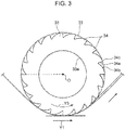
- FIG. 3 is a schematic front view of the cutter plates 33. All of the cutter plates 33 have the same shape. Specifically, they have an approximately circular disk shape formed with a through-holes 33a in a central region thereof. Each of the cutter plates 33 is fixed to the outer peripheral surface of the shaft 32 in a state in which the shaft 32 is inserted in the through-hole 33a of the cutter plate 33. Each of the cutter plates 33 is fixed such that the center thereof is located on the center line O of the shaft 32.
- a plurality of blades 34 are formed in an outer peripheral face of the cutter plate 33 along a circumferential direction of the cutter plate 33. All of the blades 34 have the same shape, and are arranged at even intervals in the circumferential direction of the cutter plate 33
- the shaft 32 is configured to be rotationally driven about the center line O of the shaft 32 by the motor 39. Upon this rotational driving, each of the cutter plates 33 is rotated about the center line O of the shaft 32 together with the shaft 32, so that the blades 34 are moved on a circumferential plane of a circular cylinder having a center line coincident with the center line O of the shaft 32.
- the tiller 31 is disposed in a posture where the center line O of the shaft 32 extends in a direction which is orthogonal to a direction parallel to the conveyance direction Y1 of the first sheet 201, and parallel to the obverse surface of the first sheet 201.
- the blades 34 are rotated along a circumferential plane of a circular cylinder having a center line which is a line O (center line O of the shaft 32) extending in a direction orthogonal to the conveyance direction of the first sheet 201 and parallel to the obverse surface of the first sheet 201.
- the broken line in FIG. 3 indicates another cutter plate 33 disposed adjacent to the cutter plate 33 indicated by the solid line.
- the adjacent two cutter plates 33 are arranged in a state in which they are shifted in phase such that each of the blades 34 of one of the cutter plates 33 is located in the middle between adjacent ones of the blades 34 of the other cutter plate 33, in front view.
- the fiber-raising device 30 is disposed at a position enabling the blades 34 to sequentially contact the short fiber sub-sheet 201b. Specifically, the fiber-raising device 30 is disposed such that the first sheet 201 is wound around part of an outer peripheral surface of the tiller 31 formed by distal edges 34c of the blades 34 of the cutter plates 33, in a posture where the obverse surface of the first sheet 201 (an obverse surface of the short fiber sub-sheet 201b) is oriented toward the tiller 31.
- the first sheet conveyance device 10 conveys the first sheet 201 in a state in which the first sheet 201 is wound around part of the outer peripheral surface of the tiller 31, and the short fiber sub-sheet 201b of the first sheet 201 is in contact with some of the distal edges 34c of the blades 34 of the cutter plates 33.
- the first sheet 201 contacts some of the blades 34 over a given circumferential range of the cutter plates 3 3.
- a movement direction (conveyance direction) Y1 of the first sheet 201 and a movement direction Y3 of the blades 34 are set to be the same, i.e., the blades 34 are moved toward a downstream side of the conveyance direction Y1 of the first sheet 201.
- a movement speed of the blades 34 and a conveyance speed of the first sheet 201 are different from each other, i.e., the first sheet 201 is moved relative to the blades 34. Accordingly, the blades 34 sequentially scratch the first sheet 201 and thus fibers of the first sheet 201 are raised.
- each of the blades 34 directly contacts only the obverse surface of the first sheet 201.
- fibers in a given region of the first sheet 201 on its reverse side are also raised, so that almost all fibers of the short fiber sub-sheet 201b can be raised in a thickness direction of the first sheet 201.
- the diffusive sub-sheet 201a is not subjected to fiber-raising.
- a circumferential movement speed of the distal edges of the blades 34 i.e., a circumferential speed of the tiller 31, at the fiber-raising position P1 is set to be less than the conveyance speed of the first sheet 201.
- the first sheet 201 is moved relative to the blades 34, toward a downstream side of the movement direction Y3 of the blades 34 (conveyance direction Y1 of the first sheet 201).
- the circumferential speed of the tiller 31 is set in the range of 40% to 80% of the conveyance speed of the first sheet 201.
- the circumferential speed of the tiller 31 is set to be greater than 80% of the conveyance speed of the first sheet 201, the relative movement of the first sheet 201 with respect to the blades 34 is likely to become excessively small, thereby leading to a problem of failing to sufficiently raise fiber of the first sheet 201.
- the circumferential speed of the tiller 31 is set to be less than 40% of the conveyance speed of the first sheet 201, each of the blades 34 is likely to be excessively engaged with the first sheet 201, thereby leading to a problem of damage to the first sheet 201. Therefore, in this embodiment, the circumferential speed of the tiller 31 is set in the range of 40% to 80%, e.g., at about 55%, of the conveyance speed of the first sheet 201.
- Each of the blades 34 has a first face 34a provided on an upstream side of the movement direction of the blades 34 and facing an upstream side of the conveyance direction Y1 of the first sheet 201, and a second face 34b extending from the distal edge 34c of the first face 34a (an outer edge of the first face 34a in a radial direction of the cutter plate 33) toward the downstream side of the movement direction of the blades 34 and an inward side of the radial direction of the cutter plate 33.
- the first face 34a extends in the radial direction of the cutter plate 33 and along a line passing through the center line O of the shaft 32.
- the second face 34b extends from the distal edge 34c of the first surface 34a toward a downstream side of a rotational direction of the cutter plate 33, while curving inwardly in the radial direction of the cutter plate 33.
- the first sheet 201 is moved relative to the blades 34, toward the downstream side of the movement direction Y3 of the blades 34 (conveyance direction Y1 of the first sheet 201), as mentioned above. Therefore, the first face 34a of the blade 34 can scratch the first sheet 201 to thereby raise fibers of the first sheet 201. More specifically, the first face 34a of the blade 34 scoopingly scratches fibers of the first sheet 201 to thereby raise the fibers of the first sheet 201.
- the cutter plates 33 are provided in a position opposed to the entire region of the first sheet 201 in its width direction, so that fibers of the first sheet 201 (short fiber sub-sheet 201b) are raised over the entire region in the width direction thereof. Further, the cutter plates 33 are continuously rotated, so that fibers of the first sheet 201 (short fiber sub-sheet 201b) are raised over the entire region in a longitudinal direction (conveyance direction) of the first sheet 201.
- the first faces 34a of the blades 34 of the cutter plates 33 may be configured such that all of them extend along the radial line passing through the center line O of the shaft 32, i.e., extend in a direction orthogonal to the conveyance direction Y1 of the first sheet 201.
- some of the first faces 34a may be formed in a shape extending in a direction oblique to the conveyance direction Y1 of the first sheet 201, i.e., formed such that each of the blades 34 thereof has a knife-like blade edge.
- the first type of cutter plate 33 with the blades 34 each having the first face 34a extending in a direction orthogonal to the conveyance direction Y1 of the first sheet 201, and the second type of cutter plate 33 with the blades 34 each having the first face 34a extending in a direction oblique to the conveyance direction Y1 of the first sheet 201, may be alternately disposed in a direction parallel to the center line of the shaft 32.
- each of the cutter plates 33 may be configured such that the first faces 34a of some of the blades 34 thereof have a shape extending in a direction orthogonal to the conveyance direction Y1 of the first sheet 201, and the first faces 34a of the remaining blades 34 have a shape extending in a direction oblique to the conveyance direction Y1 of the first sheet 201.
- fibers of the first plate 201 can be raised by the cutter plates 33, and fibers in the obverse surface of the first sheet 201 are partly cut by the blades 34 each having the knife-like blade edge to be made openings in the obverse surface of the first sheet 201.
- FIG. 5A is a view depicting the first sheet 201 before the fiber-raising
- FIG. 5B is a view depicting the first sheet 201 just after the fiber-raising.
- short fibers of the short fiber sub-sheet 201b are in a state in which they extend along the obverse surface of the first sheet 201, i.e., in a state in which they lie along the obverse surface of the first sheet 201.
- the blades 34 of the cutter plates sequentially come into contact with the first sheet 201 in the above initial state, the blades 34 pull out the fibers of the short fiber sub-sheet 201b toward the obverse side of the first sheet 201 (toward the side of the tiller 31), and accordingly the fibers reach a state in which the fibers extend toward the obverse side of the first sheet 201, as depicted in FIG. 5B .
- the thickness of the first sheet 201 short fiber sub-sheet 201b
- the density of the first sheet 201 short fiber sub-sheet 201b
- the powder supply device 40 is a device for supplying the powder S from the obverse side of the first sheet 201 to the first sheet 201.
- the powder supply device 40 comprises a powder storage unit 42, a metering unit 44, and a powder distribution unit 46.
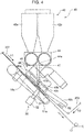
- FIG. 4 is a diagram enlargedly depicting a part of FIG. 1 and depicting an internal structure of the powder distribution unit 46.
- the powder distribution unit 46 comprises a powder guide section 47, and an opening-closing mechanism 48 comprising a housing 48a internally having a relatively wide space.
- the powder storage unit 42 is a component storing therein the powder S.
- the powder storage unit 42 comprises two tanks 42a, 42b each storing therein the powder S.
- Each of these two tanks 42a, 42b has a bottom wall formed with an opening for allowing the powder S to drop toward the metering unit 44, so that the powder is fed to the metering unit 44 via this opening.
- the metering unit 44 is a device for metering each of the powders S fed from the tanks 42a, 42b, and feeding the metered powders to the powder distribution unit 46.
- the metering unit 44 is configured to continuously convey the powder S fed from each of the tanks 42a, 42b, downwardly at a given flow rate.
- the powder S to be conveyed falls downwardly from an outlet 44a provided in a bottom wall of the metering unit 44.
- the powder guide section 47 is a component for guiding the powder falling from the outlet 44a of the metering unit 44, downwardly.
- the powder guide section 47 is composed of a vertically-extending tubular member which is internally formed with a space communicating with the outlet 44a. The powder falling from the outlet 44a of the metering unit 44 flow through the powder guide section 47, and then fall downwardly from a powder supply port 47a formed at a lower end of the powder guide section 47.
- the lower end of the powder guide section 47 formed with the powder supply port 47a is inserted into the housing 48a through a top wall of the housing 48a, so that the powder S falling from the powder supply port 47a flow into the housing 48a.
- a bottom wall of the housing 48a has a distribution port 48c which is formed at a position opposed to the powder supply port 47a to penetrate the bottom wall in an upward-rearward direction. More specifically, the distribution port 48c is disposed at a position spaced apart vertically downwardly from the powder supply port 47a, and overlapping the powder supply port 47a in top plan view (as viewed along the vertical direction). Accordingly, the powder S falling from the powder supply port 47a falls toward the distribution port 48c.
- the belt conveyer 18 is disposed beneath the distribution port 48c, so that the powder S falling toward the distribution port 48c is supplied to the first sheet 201 at a position on the belt conveyer 18, through the distribution port 48c, from the obverse side of the first sheet 201.
- the powder S is supplied to the first sheet 201 uniformly in terms of the width direction of the first sheet 201.
- the belt conveyer 18 is disposed such that a downstream end region, in the conveyance direction Y1 of the first sheet 201, of a conveyer belt 18a thereof on which the first sheet 201 is placed is located downward of an upstream end region of the conveyer belt 18a in the conveyance direction Y1 of the first sheet 201.
- the first sheet 201 receives supply of the powder S from above while being conveyed obliquely downwardly with respect to the vertical direction.
- the housing 48a is configured such that the bottom wall thereof extends parallel to the obverse surface of a part of the first sheet 201 being conveyed on the belt conveyer 18, at a position adjacent to the obverse surface of the part of the first sheet 201, and the distribution port 48c is disposed at a position adjacent to the obverse surface of the part of the first sheet 201.
- the metering unit 44 continuously conveys the powder S downwardly, as mentioned above, so that the powder S continuously falls from the powder supply port 47a toward the distribution port 48c.
- an aftermentioned shutter valve 48b provided in the opening-closing mechanism 48 is operable to intermittently restrict the powder S from reaching the first sheet 201. This allows the powder S to be intermittently supplied to the first sheet 201.
- the opening-closing mechanism 48 is provided with a shutter value 48b fixed to the housing 48a in a rotatable state.
- This shutter value 48b is configured to periodically pass through a region between the powder supply port 47a and the distribution port 48c to cover an upper side of the distribution port 48c to thereby periodically restrict the powder S from reaching the distribution port 48c.
- the shutter valve 48b is a plate-shaped member extending parallel to the part of the first sheet 201 being conveyed on the belt conveyer 18, wherein the shutter valve 48b is configured to be rotationally driven on a plane parallel to the part of the first sheet 201 by a motor, so as to periodically pass through the region between the powder supply port 47a and the distribution port 48c.
- the shutter valve 48b periodically restricts the powder S from reaching the first sheet 201 via the distribution port 48c, so that the powder S is intermittently supplied from the distribution port 48c to the first sheet 201.
- a component designated by the reference sign 49b is a discharger for discharging, to the outside, a part of the powder S within the housing 48a, scattered around the distribution port 48c when the shutter valve 48b restricts the powder S from reaching the first sheet 201.
- the suction device 50 is a device for suctioning the part of the first sheet 201 being conveyed on the belt conveyer 18 from the reverse side of the first sheet 201.
- the suction device 50 comprises a suction passage 51 formed with a suction port 51a, and a suction pump 52 connected to the suction passage 51, wherein the suction device 50 is configured to suck in air surrounding the suction port 51a by driving of the suction pump 52.
- the suction port 51a is disposed around a position opposed to the distribution port 48c.
- the suction port 51a extends from a position just below the distribution port 48c to a position downstream of the distribution port 48c in the conveyance direction Y1 of the first sheet 201, so that the suction device 50 can suction the reverse surface of a part of the first sheet 201 passing through a region from the position just below the distribution port 48c to the position downstream of the distribution port 48c in the conveyance direction Y1 of the first sheet 201.
- the suction port 51a is disposed on a reverse side of the conveyer belt 18a, and configured to suction the part of the first sheet 201 via a plurality of air holes formed in the conveyer belt 18a.
- the first adhesive application device 82 is a device for applying an adhesive to the second sheet 202.
- the first adhesive application device 82 may be designed to apply a hot-melt adhesive to the second sheet 202.
- the first adhesive application device 82 is disposed on the conveyance path of the second sheet 202 at a position upstream of the guide roll 21, as mentioned above, and configured to apply an adhesive to a surface of the second sheet 202 at a position before reaching to the obverse surface of the first sheet 201.
- the second sheet 202 applied with the adhesive is covered over the first sheet 201 by the guide roll 21, and, during the covering, the first sheet 201 and the second sheet 202 are adhesively bonded together.
- the guide roll 21 functions as a second sheet supply section for supplying the second sheet 202 to the obverse surface of the first sheet 201, and further functions as a bonding device for adhesively bonding the two sheets 201, 202 together.
- the guide roll 21 is configured to pressure-join the two sheets 201, 202 bonded together, in a thickness direction of them.
- the first sheet 201 and the second sheet 202 are bonded together while being pressure-joined in the thickness direction of them.
- the second adhesive application device 84 is located downstream of the guide roll 21 in the conveyance direction of the first sheet 201.
- the second adhesive application device 84 is a device for applying an adhesive to part of a region of the second sheet 202 protruding outwardly from the first sheet 201.
- the second adhesive application device 84 may be designed to apply a hot-melt adhesive to the second sheet 202.
- the second sheet 202 is composed of a sheet having a width greater than that of the first sheet 201.
- the second sheet 202 on the first sheet 201 will protrude outwardly with respect to the first sheet 201 in the width direction thereof.
- width-directional opposite end portions of the second sheet 202 protrude outwardly with respect to the first sheet 201.
- the second adhesive application device 84 is operable to apply an adhesive to the width-directional opposite end portions of the second sheet 202.
- the folding device 60 is a device for holding the second sheet 202 such that the second sheet 202 enfolds the first sheet 201, as depicted in FIG. 5E . More specifically, the folding device 60 is configured to fold the width-directional opposite end portions of the second sheet 202 such that it wraps around the reverse side of the first sheet 201 to extend along the reverse surface of the first sheet 201.
- the folding device 60 is located downstream of the second adhesive application device 84 in the conveyance direction of the first sheet 201. In this embodiment, the folding device 60 is located immediately downstream of the second adhesive application device 84.
- the folding device 60 also functions as a bonding device for adhesively bonding the first sheet 201 and the second sheet 202 together.
- the pressure-joining device 70 is a device for pressure-joining an assembly of the first sheet 201 and the second sheet 202 bonded together, in a thickness direction thereof.
- the pressure-joining device 70 comprises a pair of rollers 72, 72, wherein the pressure-joining device 70 is configured to allow the assembly of the first sheet 201 and the second sheet 202 to pass through between the rollers 72, 72 so as to pressure-join the assembly in the thickness direction thereof.
- a method for manufacturing a powder-containing article 2 containing a powder S, by the manufacturing apparatus 1 configured as described above is as follows.
- a first sheet 201 is prepared in which a portion thereof to be subjected to fiber-raising in an aftermentioned fiber-raising step, i.e., a portion thereof exposed to an obverse side of the first sheet 201 is composed of a short fiber sub-sheet 201b comprised of a non-woven fabric of short fibers (preparation step). Subsequently, the first sheet 201 is conveyed along a conveyance path L1 (conveyance step).
- the first sheet 201 is subjected to fiber-raining using the fiber-raising device 30 to thereby shift the state of the first sheet 201 from the state depicted in FIG. 5A to the state depicted in FIG. 5B (fiber-raising step A1).
- the powder S is supplied from the powder supply device 40 to the first sheet 201 from the obverse side thereof, and introduced to and held in the inside of the first sheet 201, to thereby shift the state of the first sheet 201 from the state depicted in FIG. 5B to the state depicted in FIG. 5C (powder supply step A2).
- the powder S is supplied to the first sheet 201 from the obverse side thereof, while the first sheet 201 is suctioned from a reverse side thereof by the suction device 50.
- a second sheet 202 is supplied to an obverse surface of the first sheet 201 after being supplied with the powder S (second sheet supplying step A3).
- the second sheet supplying step after an adhesive is applied onto the second sheet 202 by the first adhesive application device 82, the second sheet 202 is supplied to the obverse surface of the first sheet 201.
- the first sheet 201 and the second sheet 202 are bonded together while pressure-joining them in their thickness direction, to thereby shift the state of the first sheet 201 from the state depicted in FIG. 5C to the state depicted in FIG. 5D (first bonding step A3, bonding step).
- the second sheet 202 is folded to bond the two sheets 201, 202 together, by the folding device bonding device 60, to thereby shift the state of an assembly of the two sheets 201, 202 from the state depicted in FIG. 5D to the state depicted in FIG. 5E (second bonding step A4, bonding step).
- the assembly of the first sheet 201 and the second sheet 202 bonded together is pressure-joined in a thickness direction thereof by the pressure-joining device 70, to thereby shift the state of the assembly of the two sheets 201, 202 from the state depicted in FIG. 5E to the state depicted in FIG. 5F (pressure-joining step A5) to manufacture a powder-containing article 2 containing a liquid-absorbable powder S.
- the powder S is intermittently supplied from the powder supply device 40 in the conveyance direction of the first sheet 201, as mentioned above.
- the powder-containing article 2 is appropriately cut in a zone thereof in which the powder S is not placed , and used as an absorbent body of a diaper, or the like.
- fibers of the short fiber sub-sheet 201b of the first sheet 201 exposed to the obverse surface thereof are raised from the obverse side thereof.
- the powder S supplied to the first sheet 201 from the obverse side thereof is introduced into the first sheet 201, so that it is possible to manufacture a powder-containing article 2 in which particles of the powder S are moderately dispersed and stably disposed at adequate positions.
- fibers of the first sheet 201 extend along the obverse surface of the first sheet 201 while being superimposed on each other in the thickness direction of the first sheet 201, as depicted in FIG. 5A .
- the powder S is supplied to the obverse surface of the first sheet 201 in the above state, the powder S is merely placed on the obverse surface of the first sheet 201 without being introduced to the inside of the first sheet 201.
- the first embodiment by raising fibers of the first sheet 201, spaces are formed between respective ones of fibers composing the first sheet 201 (short fiber sub-sheet 201b), and particles of the powder S supplied to the first sheet 201 (short fiber sub-sheet 201b) are introduced into the spaces (inter-fiber spaces). Therefore, it is possible to interpose one or more fibers between adjacent ones of the particles of the powder S to restrict displacement of the particles of the powder S by the fibers. Therefore, it is possible to manufacture a powder-containing article 2 in which particles of the powder S are moderately dispersed and adequately and stably disposed at desired positions. Further, in a powder-containing article 2 containing a liquid-absorbable powder S, it is possible to suppress displacement or positional bias of the liquid-absorbable powder S, and occurrence of the gel block, to enhance liquid absorbability.
- the first sheet 201 (short fiber sub-sheet 201b) becomes soft as a result of the fiber-raising, and has an excellent cushioning function, so that it is possible to suppress a situation where, when the powder S is supplied to the first sheet 201, some particles of the supplied powder S bounce from and drop out of the first sheet 201. Therefore, it is possible to efficiently supply the powder S to the first sheet 201.
- the powder S is supplied from the obverse side of the first sheet 201 while the first sheet 201 is suctioned from the reverse side thereof by the suction device 50.
- particles of the powder S can be dispersedly arranged within the first sheet 201 (short fiber sub-sheet 201b) in the thickness direction of the first sheet 201. Therefore, the particles of the powder S can bury, respectively, in the inter-fiber spaces, so that it is possible to more reliably interpose one or more fibers between adjacent ones of the particles of the powder S.
- the suction port 51a of the suction device 50 is provided between the position beneath the distribution port 48c, i.e., the position opposed to the distribution port 48c, and the positon downstream of the distribution port 48c in the conveyance direction Y1 of the first sheet 201, to thereby suppress a situation where a suction force by the suction device 50 is given to the first sheet 201 at a position before reaching the powder supply position. Therefore, a situation can be suppressed in which raised fibers lie down due to the suction force before supplying the powder S, so that it is possible to form spaces between respective ones of the fibers to reliably introduce particles of the powder S into the inter-fiber spaces.
- the diffusive sub-sheet 201a composing the reverse surface and its adjacent portion of the first sheet 201 is not subjected to fiber-raising.
- the density of the reverse surface and its adjacent portion of the first sheet 201 can be maintained at a higher value than that of the remaining portion on the obverse side of the first sheet 201, so that it is possible to suppress a situation where the powder S escapes through the reverse side of the first sheet 201, while allowing particles of the powder S to be introduced to the inside of the first sheet 201 from the obverse side thereof and moderately dispersed, as mentioned above, and thus efficiently dispersedly arrange the particles of the powder S within the first sheet 201.
- the reverse surface of the first sheet 201 is composed of the diffusive sib-sheet 201b having a relatively high density, and this diffusive sib-sheet 201b is maintained in the high density state without being subjected to fiber-raising. Therefore, it is possible to more reliably restrict the powder S from escaping toward the reverse side of the first sheet 201, by the diffusive sub-sheet 201b.
- fibers composing a portion of the first sheet 201 to be subjected to fiber-rising are short fibers.
- distal ends of raised fibers of the first sheet 201 are more exposed to the obverse side of the first sheet 201, so that many of spaces formed between respective ones of the fibers (inter-fiber spaces) can be opened on the obverse side of the first sheet 201. Therefore, it is possible to allow particles of the powder S to more reliably flow into the inter-fiber spaces through the openings around the distal ends of the raised fibers.
- a portion of the first sheer to be subjected to fiber-raising may be comprised of a non-woven fabric composed of long fibers.
- the fibers can also be pulled out toward the obverse side of the first sheet 201 by fiber-raising so as to form spaces between respective ones of the fibers of the first sheet 201.
- a frequency that an inter-fiber space is opened on the obverse side of the first sheet is kept down, and thereby the powder S is less likely to be introduced to the inside of the first sheet.
- the fiber-raising device needs to be designed to have a structure suited to a non-woven fabric of long fibers, or needs to be operated under operation conditions suited to a non-woven fabric of long fibers.
- the obverse side of the first sheet 201 is comprised of a non-woven fabric of short fibers, so that fiber-raising can be easily achieved by the fiber-raising device 30 configured as described above, and, through the fiber-raising, it is possible to obtain a state in which distal ends of many of the fibers are exposed to the obverse side of the first sheet 201. Therefore, particles of the powder S are allowed to move to the inside of the first sheet 201 via openings around the distal ends of the fibers, i.e., can be more reliably introduced into the inter-fiber spaces.
- the first sheet 201 and the second sheet 202 are bonded together by the guide roll 21 and the folding device 60.
- the powder S in the first sheet 201 can be confined therein by the second sheet 202, so that it is possible to avoid leakage of the powder S from between the first sheet 201 and the second sheet 202. Therefore, the powder S can be adequately contained in the powder-containing article 2.
- the second sheet 202 is supplied to and bonded to the obverse surface of the first sheet 201, in the vicinity of the powder supply position where the powder S is supplied to the first sheet 201.
- the folding device 60 the first sheet 201 and the second sheet 202 are bonded together in a state in which the width-directional opposite end portions of the second sheet 202 enfolds the first sheet 201.
- the width-directional opposite end portions of the second sheet 202 enfolds the first sheet 201.
- the first sheet 201 and the second sheet 202 are pressure-joined by the pressure-joining device 70.
- the pressure-joining device 70 it is possible to keep down the thickness of the powder-containing article 2.
- particles of the powder S can be securely pressed by surrounding fibers.
- the blades 34 are moved from the upstream side to the downstream side of the conveyance direction Y1 of the first sheet 201 under the condition that the movement direction Y3 of the blades 34 is coincident with the movement direction Y1 of the first sheet 201. Further, the movement speed of the blades 34 is set to be less than the movement (conveyance) speed of the first sheet 201.
- the conveyance speed of the first sheet 201 it is possible to increase the conveyance speed of the first sheet 201 to enhance efficiency regarding manufacturing of the powder-containing article 2, and keep down the relative speed between the first sheet 201 and the blades 34, to suppress a situation where the first sheet 201 is excessively engaged with each of the blades 34, leading to damage to the first sheet 201, and a situation where, due to such excessive engagement, the conveyance speed of the first sheet 201 largely fluctuates, and thus convey the first sheet 201 toward the downstream sided, in an adequate state and at an adequate speed.
- the blades 34 are moved in a direction opposite to the conveyance direction Y1 of the first sheet 201, at the fiber-raising position P1, i.e., the blades 34 are moved from the downstream side to the upstream side of the conveyance direction Y1 of the first sheet 201, under the condition that the conveyance speed of the first sheet 201 is increased, the movement speed of the first sheet 201 becomes extremely high, relative to the movement speed of the blades 34. Thus, when they come into contact with each other, the first sheet 201 is likely to be excessively engaged with each of the blades 34.
- the movement direction Y3 of the blades 34 and the conveyance direction Y1 of the first sheet 201 are the same at the fiber-raising position P1, so that it is possible to keep down the relative speed therebetween to thereby suppress the situation where the first sheet 201 is excessively engaged with each of the blades 34.
- the first sheet 201 is moved relative to the blades 34, from the downstream side to the upstream side of the movement direction of the blades 34, it is possible to bring the first sheet 201 into contact with a portion of each of the blades 34 on the downstream side of the movement direction of the blades 34 to raise fibers of the first sheet 201.
- the movement direction Y3 of the blades 34 is set to be the same as the conveyance direction Y1 of the first sheet 201, and the movement speed of the blades 34 is set to be less than the conveyance speed of the first sheet 201.
- the obverse surface of the first sheet 201 is moderately engaged with each of the blades 34, while the conveyance speed of the first sheet 201 is maintained at a relatively high value, so that fibers of the first sheet 201 can be successfully raised.
- the first face 34a which is an upstream-side face in the movement direction of the blades 34 and faces the upstream side of the conveyance direction Y1 of the first sheet 201 at the fiber-raising position P1 extends in the radial direction of the cutter plate 33
- the second face 34b which is a downstream-side face in the movement direction of the blades 34 and faces the downstream side of the conveyance direction Y1 of the first sheet 201 at the fiber-raising position P1 extends from the outer edge 34c of the first face 34a in the radial direction of the cutter plate 33, toward the downstream side of the movement direction of the blades 34 and the inward side of the radial direction of the cutter plate 33.
- the distal edge 34c of each of the blades 34 which is a portion contactable with the first sheet 201 is formed in a shape sharp-edged toward an outward side of the radial direction of the cutter plate 33.
- the distal edge 34c of the blade 34 can be adequately engaged with the first sheet 201 to raise fibers of the first sheet 201.
- first face 34a contactable with the first sheet 201 extends in a direction orthogonal to the obverse surface of the first sheet 201, at the fiber-raising position P1.
- fibers of the first sheet 201 are more likely to be released from the blade 34, so that it is possible to adequately convey the first sheet 201. That is, each of the blades 34 can be smoothly separated from the first sheet 201, so that it is possible to suppress a situation where the first sheet 201 is damaged due to excessive engagement between each of the blades 34 and the first sheet 201.
- the conveyer belt 18a of the belt conveyer 18 is disposed to extend obliquely downwardly with respect to the vertical direction, to convey the first sheet 201 obliquely downwardly at a position opposed to the distribution port 48c.
- both of a movement direction of the powder S falling from the distribution port 48c and the conveyance direction of the first sheet 201 can be set to extend vertically downwardly, so that it is possible to suppress a situation where some particles of the powder S bounce from and drop out of the first sheet 201, and thus efficiently supply the powder S to the first sheet 201.
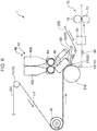
- a conveyance drum 518 may be used in place of the belt conveyer 18, as depicted in FIG. 6 .
- the first sheet 201 after being subjected to fiber-raising is supplied to an outer peripheral surface of the conveyance drum 518.
- the powder S is supplied to the first sheet 201 at a position along the outer peripheral surface of the conveyance drum 518, and then, through the guide roll 21, the second sheet 202 is supplied to the first sheet 201 at a position along the outer peripheral surface of the conveyance drum 518.
- the first sheet 201 and the second sheet 202 to which an adhesive is applied by the first adhesive application device 82 are bonded together while being pressure-joined in the thickness direction of them.
- a plurality of air holes may be formed in the outer peripheral surface of the conveyance drum 518, and communicated with the suction device 50 such that the first sheet 201 can be suctioned from the reverse side thereof via the air holes.
- the conveyance drum 518 By using the conveyance drum 518 in this manner, a device size in the conveyance direction of the first sheet 201, and a device installation area can be reduced as compared to the belt conveyer 18.
- the belt conveyer 18 makes it possible to avoid a situation where centrifugal force is applied to the first sheet 201 and the powder S as in the case using the conveyance drum 518, and thus more efficiently supply the powder S to the first sheet 201.
- the first embodiment has been described based on an example in which the guide roll 21 of the second sheet conveyance device 20 for supplying the second sheet 202 to the obverse surface of the first sheet 201 is disposed downstream (in the conveyance direction Y1 of the first sheet 201) of the position opposed to the distribution port 48c, i.e., downstream (in the conveyance direction Y1 of the first sheet 201) of the powder supply position where the powder S is supplied to the first sheet 201.
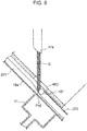
- the guide roll 21 may be disposed as depicted in FIG. 7 and FIG. 8 in which a part of FIG. 7 is enlargedly depicted.
- one 121 of two guide rolls of a second sheet conveyance device 20 for supplying the second sheet 202 to the obverse surface of the first sheet 201 is disposed at the position opposed to the distribution port 48c, i.e., at the powder supply position where the powder S is supplied to the first sheet 201.
- the first sheet 201 is conveyed obliquely downwardly, as with the first embodiment.
- a second sheet supply position P10 where the second sheet 202 is supplied to the obverse surface of the first sheet 201 through the guide roll 121 is located upstream, in the conveyance direction of the first sheet 201, of a position vertically downward of a shaft center of the guide roll 121, and an upper side, in the vertical direction, of the second sheet supply position position P10 is opened.
- the distribution port 48c is disposed to face a position upward, in the vertical direction, of the second sheet supply position position P10.
- the powder supply position where the powder S is supplied to the first sheet 201 and the second sheet supply position P10 where the second sheet 202 is supplied to the first sheet 201 are coincident with each other, so that, at this position, the powder S is supplied to the second sheet 201, and simultaneously the second sheet 202 is supplied to the first sheet 201. Therefore, in the third embodiment, it is possible to more reliably suppress leakage of the powder S from between the two sheets 201, 202.
- a first adhesive application device 181 is provided at a position upstream, in the conveyance direction of the second sheet 202, of the guide roll 121, so that, simultaneously with supply of the powder S to the first sheet 201, the first sheet 201 and the second sheet 202 are bonded together.
- the guide roll 121 is configured to pressure-join the first sheet 201 and the second sheet 202 in their thickness direction, in the same manner as that in the first embodiment.
- the suction passage 51 extends toward the downstream side from a position just below the distribution port 48c, i.e., the powder supply position where the powder S is supplied to the first sheet 201, and applies suction to a region from the powder supply position to a position downstream of the powder supply position, in the same manner as that in the first embodiment.
- a second adhesive application device 183, a folding device 185 and a pressure-joining device 70 are provided, and the second sheet 201 and the second sheet 202 are further bonded together and an assembly thereof is pressure-joined in a thickness direction thereof, in the same manner as that in the first embodiment.
- one type of SAP powder having a single absorption property may be used, or a mixture of one type of SAP powder having a high liquid-absorbability and another type of SAP powder having a high absorption rate may be used.
- the type of SAP powder having a high liquid-absorbability and the type of SAP powder having a high absorption rate are stored, respectively, in the tank 42a and the tank 42b of the powder storage unit 42 depicted in FIG. 1 , and the two type of SAP powders are fed from the two tanks 42a, 42b at a given ratio.
- the powder S may be any liquid-absorbable powder other than the SAP powders. Further, the powder S is not limited to a liquid-absorbable powder. For example, as the powder S, a powder of cool sensation material or fragrance material may be used. Further, the plural types of powders may be used in combination.
- a specific configuration of the first sheet 201 is not limited to the aforementioned configuration, as long as at least a given region from the obverse surface toward the reverse side of the first sheet 201 is comprised of a non-woven fabric.
- the non-woven fabric as an obverse-side portion may be configured as a single layer or may be configured as a multilayer.
- a reverse-side portion may be comprised of a non-woven fabric of long fibers, such as a diffusive sub-sheet, or may be a non-woven fabric of short fibers, or a synthetic resin sheet.
- the "given region from the obverse surface toward the reverse side" may be the entire region of the first sheet 201.
- the diffusive sub-sheet 201a may be omitted.
- the reverse surface of the first sheet 201 is composed of a sheet having a relatively high density, it is possible to suppress a situation where the powder S escapes to the reverse side through the first sheet 201, and thud efficiently arrange particles of the powder S within the first sheet 201.
- a sheet comprising a short fiber sub-sheet formed by processing other than air-through processing may be used.
- a non-woven fabric composing the entire region of the first sheet 201 or the given region from the obverse surface toward the reverse side of the first sheet 201 a non-woven fabric composed of long fibers may be used.
- the use of short fibers makes it possible to more reliably bury particles of the powder S inside the first sheet 201.
- the second sheet 202 is not limited to a tissue paper.
- it may be comprised of a non-woven fabric.
- only a partial zone of the first sheet 201 may be subjected to fiber-raising.
- the powder S is supplied to only a width-directional intermediate zone of the first sheet 201, or supplied at given intervals in the width direction and/or the longitudinal direction of the first sheet 201, only such a powder supply zone to which the powder S is to be supplied may be subjected to fiber-raising.
- only part of the powder supply zone may be subjected to fiber-rising.
- fibers of the first sheet 201 may be raised by rubbing the obverse surface of the first sheet with a friction material composed of a non-woven fabric.
- one or more blades 34 are provided which protrude toward the obverse surface of the first sheet 201 and contact the obverse surface of the first sheet 201, in the same manner as that in the above embodiments, wherein the blades 34 may contact the first sheet 201 without moving the blades 34. Further, the blades 34 may be moved in a direction parallel to the conveyance direction of the first sheet 201, without rotationally moving the cutter plates 33.
- the above configuration using the tiller 31 makes it possible to raise fiber of the first sheet 201 with a simple configuration.
- each of the blade 34 is not limited to the aforementioned shape.
- the upstream-side face and the downstream-side face of the blade 34 in the movement direction of the blades 34 may have the same shape.
- the movement speed of the blades 34 is not limited to the aforementioned speed.
- the number of blades 34 formed in each of the cutter plates 33 may be one.
- the rotational speed and the rotational direction of the tiller 31 may be appropriately changed.
- the conveyance direction of the first sheet 201 is not limited thereto.
- the first sheet 201 may be conveyed horizontally or obliquely upwardly.
- the process and device for pressure-joining the two sheets 201, 202 are not limited thereto.
- the pressure-joining device 70 may be omitted.
- a specific configuration for bonding the two sheets 201, 202 together is not limited thereto.
- the two sheets 201, 202 may be bonded together by means of heat-sealing or ultrasonic bonding.
- this flow rate may be constant or may be temporally changed.
- the flow rate may be increased at a timing corresponding to the given zone.
- a specific configuration of the metering unit 44 is not limited to the aforementioned configuration.
- a supply amount of the powder S to the first sheet S may be changed in the width direction of the first sheet 201.
- the powder guide section 47 may be divided, in the width direction of the first sheet 201, into a plurality of discrete passages, such that the powder S falls downwardly through respective ones of the discrete passages. Further, at least part of the powder S passing through some of the discrete passages may be appropriately removed from the some passages by removing means (mechanical means, blow means using airflow, or suction means) to change the supply amount of the powder S to the first sheet S in the width direction of the first sheet 201.
- means mechanical means, blow means using airflow, or suction means
- the powder S may be continuously supplied to the first sheet 201.
- the first sheet 201 can be cut in each of the specific zones. In this case, it is possible to suppress leakage of the powder S through the resulting cut surface. In addition, it is possible to suppress damage to a cutter plate for use in the cutting, due to interference with particles of the powder S.
- a specific configuration for supplying the powder S to the first sheet 201 is not limited to the aforementioned configuration.
- an adhesive is applied onto the width-directional opposite end portions of the second sheet 202, and, by the folding device 60, the second sheet 202 applied with the adhesive is folded, and and bonded to the first sheet 201.
- an adhesive may be applied onto one of the width-directional opposite end portions of the second sheet 202 by the second adhesive application device 84, and the second sheet 202 applied with the adhesive may be folded by the folding device 60, such that the width-directional opposite end portions of the second sheet 202 are superimposed on each other on the first sheet 201 and bonded together, whereby the first sheet 201 can be enfolded by the second sheet 202.
- a third adhesive application device may be disposed between the fiber-raising device 30 and the powder supply device 40, wherein after applying an adhesive to the obverse surface of the first sheet 201 whose fibers have been raised by the fiber-raising device, by means of spraying or the like, the powder S may be supplied to the obverse surface of the first sheet 201 applied with the adhesive.
- the powder S may be supplied to the obverse surface of the first sheet 201 applied with the adhesive.
- at least part of particles of the powder S are fixed to the first sheet 201 by the adhesive, so that it is possible to further suppress the displacement of particles of the powder S.
- the present invention provides an apparatus for manufacturing a powder-containing article containing a powder.
- the apparatus comprises: a sheet conveyance device which conveys, along a conveyance path, a sheet in which a given region from an obverse surface toward a reverse side thereof is composed of a non-woven fabric; a powder supply device which is provided on the conveyance path, and supplies the powder to at least a partial zone of the sheet, from an obverse side of the sheet; and a fiber-raising device which is provided on the conveyance path at a position upstream, in a conveyance direction of the sheet, of a powder supply position where the powder is supplied to the sheet, and raises fibers in at least part of the powder supply zone of the sheet, from the obverse side of the sheet.
- fibers in at least part of the powder supply zone of the sheet in which a given region from the obverse surface toward the reverse side thereof is composed of a non-woven fabric are raised, so that inter-fiber spaces can be formed in the powder supply zone.
- particles of the powder can be buried in the inter-fiber spaces, and fibers of the sheet can be interposed between respective ones of the powder particles. Therefore, it is possible to restrict free displacement of the powder particles by the fibers, and thus manufacture a powder-containing article in which the powder particles are stably arranged at adequate positions.
- the fibers can be interposed between respective ones of the powder particles, so that it is possible to suppress a situation where the powder is biased to one area, i.e., to moderately disperse the powder particles.
- the powder particles can be buried in the inter-fiber spaces as mentioned above, so that it is possible to suppress a situation where, when the powder is supplied to the sheet, the powder particles bounces from the sheet, thereby efficiently supplying the powder to the sheet.
- the apparatus of the present invention comprises: a second sheet supply section which is provided on the conveyance path, and supplies a second sheet to the obverse surface of the sheet, at the powder supply position position, or a position downstream, in the conveyance direction of the sheet, of the powder supply position; and a bonding device which is provided on the conveyance path, and bonds the sheet and the second sheet together at a second sheet supply position where the second sheet is supplied to the obverse surface of the sheet by the second sheet supply section, or a position downstream, in the conveyance direction of the sheet, of the second sheet supply position.
- the second sheet is supplied to the obverse surface of the sheet supplied with the powder, and the two sheets are bonded together to confine the powder in the sheet by the second sheet, so that it is possible to suppress leakage of the powder from the obverse surface of the sheet.
- the above apparatus comprises a pressure-joining device which is provided on the conveyance path at a position downstream, in the conveyance direction of the sheet, of the bonding device, and pressure-joins an assembly of the sheet and the second sheet in a thickness direction thereof.
- the thickness of the sheet increased by the fiber-raising can be reduced again while restricting displacement of the powder particles by the raised fibers of the sheet, so that it is possible to manufacture a powder-containing article whose thickness is kept down. Further, by keeping down the thickness of the sheet, a space for allowing displacement of the powder particles is narrowed, so that it is possible to more reliably restrict the free displacement of the powder particles.
- the bonding device bonds the sheet and the second sheet together while pressure-joining them in their thickness direction.
- the two sheets can be bonded together and press-joined by the bonding device, so that it is possible to structurally simplify the entire apparatus.
- the fiber-raising device comprises one or more blades each protruding toward the obverse surface of the sheet to contact the sheet, and wherein the sheet conveyance device conveys the sheet such that the sheet is moved relative to the one or more blades.
- fibers of the sheet can be raised by a simple configuration in which the obverse surface of the sheet is scratched by the one or more blades provided in the fiber-raising device.
- the fiber-raising device comprises a drive section which moves the one or more blades from an upstream side toward a downstream side of the conveyance direction of the sheet, at a movement speed less than a movement speed of the sheet.
- the relative speed of the obverse surface of the sheet with respect to the one or more blades can be kept down while the conveyance speed of the sheet is maintained at a relatively high value, so that it is possible to more reliably suppress damage to the sheet when the one or more blades are engaged with the sheet.
- the relative speed of the sheet with respect to the one or more blades is excessively increased, so that the one or more blades are likely to be excessively engaged with the sheet, leading to damage to the sheet.
- a movement direction of the one or more blades is set to be the same as the conveyancer direction of the sheet.
- the relative speed of the sheet with respect to the one or more blades can be kept down, so that it is possible to suppress excessive engagement of the sheet with the one or more blades.
- the movement speed of the one or more blades is set to be greater than the conveyance speed of the sheet, and the sheet is moved relative to the one or more blades, from the downstream side to the upstream side of the movement direction of the one or more blades, wherein the sheet is engaged with a portion of each of the one or more blades on the downstream side of the movement direction of the one or more blades.
- the movement direction of the one or more blades is set to be the same as the conveyance direction Y1 of the sheet, and the movement speed of the one or more blades is set to be less than the conveyance speed of the sheet.
- the sheet is moderately engaged with each of the one or more blades while the conveyance speed of the sheet is maintained at a relatively high value, so that fibers of the sheet can be successfully raised.
- the sheet is moved relative to the one or more blades, from the downstream side to the upstream side of the movement direction of the one or more blades, wherein the sheet is engaged with an upstream-side portion of each of the one or more blades.
- the drive section rotationally drives the one or more blades along a circumferential plane of a circular cylinder having a center line which is a line extending in a direction orthogonal to the conveyance direction of the sheet and parallel to the obverse surface of the sheet; and each of the one or more blades has a first face facing the upstream side of the conveyance direction of the sheet at a contact position with the sheet, and a second face facing the downstream side of the conveyance direction of the sheet at the contact position, wherein the first face has a shape extending in a radial direction of the circular cylinder, and the second face has a shape extending from an outer edge of the first face in the radial direction of the circular cylinder, toward a downstream side of the movement direction of the one or more blades and an inward side of the radial direction of the circular cylinder.
- the radially-outer edge of each of the one or more blades which is a portion capable of scratching the sheet is formed in a shape sharp-edged toward an outward side of the radial direction, so that the outer edge of the blade can be engaged with the sheet to adequately raise fibers of the sheet.
- the first face extends in the radial direction, so that, when the blade is separated from the sheet, fibers of the sheet are more likely to be released from the blade, so that it is possible to adequately convey the sheet while adequately raising fibers of the sheet.
- the powder supply device has a distribution port for distributing the powder over the sheet from the obverse side of the sheet
- the apparatus for manufacturing a powder-containing article containing a powder comprises a suction device which suctions the sheet from the reverse side of the sheet, in at least part of a region from a position opposed to the distribution port to a position downstream of the opposed position in the conveyance direction of the sheet.
- the powder particles can be reliably buried in the inter-fiber spaces and stably held inside the sheet. Specifically, if the sheet is suctioned from the reverse side thereof by the suction device before supplying the powder, raised fibers of the sheet are likely to lie down due to a suction force of the suction device, leading to breakage of the inter-fiber spaces. Compared with this, according to the above feature, at the same time or after the powder is supplied to the sheet, the sheet is suctioned from the reverse side thereof, so that it is possible to suppress breakage of the inter-fiber spaces and more reliably bury the powder particles in the inter-fiber spaces.
- the sheet conveyance device conveys the sheet obliquely downwardly with respect to a vertical direction, at the opposed position.
- the direction of the powder particles moving vertically downwardly by gravity becomes close to the movement direction of the sheet, so that it is possible to suppress a situation where the powder particles bounce from the sheet and drop out of the sheet, and thus efficiently supply the powder to the sheet.
- the present invention further provides a method for manufacturing a powder-containing article containing a powder.
- the method comprises: a conveyance step of conveying, along a conveyance path, a sheet in which a given region from an obverse surface toward a reverse side thereof is composed of a non-woven fabric; a powder supply step of supplying the powder to at least a partial zone of the sheet being conveyed along the conveyance path, from an obverse side of the sheet; and a fiber-raising step of raising, from the obverse side of the sheet, fibers in at least part of the powder supply zone of the sheet being conveyed along the conveyance path, at a position of the conveyance path upstream, in a conveyance direction of the sheet, of a powder supply position where the powder is supplied to the sheet.
- fibers in at least part of the powder supply zone of the sheet are raised, so that inter-fiber spaces can be formed in the powder supply zone.
- the powder when the powder is supplied to the powder supply zone from the obverse side, particles of the powder can be buried in the inter-fiber spaces, and fibers of the sheet can be interposed between respective ones of the powder particles. Therefore, it is possible to restrict free displacement of the powder particles by the fibers, and thus manufacture a powder-containing article in which the powder particles are stably arranged at adequate positions.
- the fibers can be interposed between respective ones of the powder particles, so that it is possible to suppress a situation where the powder is biased to one area, i.e., to moderately disperse the powder particles.
- the powder particles can be buried in the inter-fiber spaces as mentioned above, so that it is possible to suppress a situation where, when the powder is supplied to the sheet, the powder particles bounces from the sheet, and thus efficiently supply the powder to the sheet.
- the method of the present invention comprises: a second sheet supply step of supplying a second sheet to the obverse surface of the sheet being conveyed along the conveyance path, at the powder supply position, or a position downstream, in the conveyance direction of the sheet, of the powder supply position; and a bonding step of bonding the sheet and the second sheet supplied to the obverse surface of the sheet, together.
- the second sheet is supplied to the obverse surface of the sheet supplied with the powder, and the two sheets are bonded together to confine the powder in the sheet by the second sheet, so that it is possible to suppress leakage of the powder from the obverse surface of the sheet.
- the above method of the present invention comprises a pressure-joining step of pressure-joining an assembly of the sheet being conveyed along the conveyance path and the second sheet bonded to the sheet, in a thickness direction thereof.
- the thickness of the sheet increased by the fiber-raising can be reduced again while restricting displacement of the powder particles by the raised fibers of the sheet, so that it is possible to manufacture a powder-containing article whose thickness is kept down. Further, by keeping down the thickness of the sheet, a space for allowing displacement of the powder particles is narrowed, so that it is possible to more reliably restrict the free displacement of the powder particles.
- the bonding step includes bonding the sheet and the second sheet together while pressure-joining them in their thickness direction.
- the two sheets can be bonded together and press-joined, so that it is possible to simplify a manufacturing process.
- the method of the present invention comprises a preparation step of, prior to the conveyance step, preparing a sheet whose portion to be subjected to fiber-raising in the fiber-raising step is comprised of a non-woven fabric composed of short fibers.
- short fiber here means a fiber having a fiber length of less than 100 mm, preferably less than 80 mm, more preferably less than 70 mm, as measured by the average fiber length measurement method (C method) defined in JIS 1015.
Landscapes
- Health & Medical Sciences (AREA)
- Engineering & Computer Science (AREA)
- Animal Behavior & Ethology (AREA)
- General Health & Medical Sciences (AREA)
- Biomedical Technology (AREA)
- Heart & Thoracic Surgery (AREA)
- Vascular Medicine (AREA)
- Life Sciences & Earth Sciences (AREA)
- Veterinary Medicine (AREA)
- Epidemiology (AREA)
- Public Health (AREA)
- Textile Engineering (AREA)
- Manufacturing & Machinery (AREA)
- Chemical & Material Sciences (AREA)
- Materials Engineering (AREA)
- Absorbent Articles And Supports Therefor (AREA)
- Treatment Of Fiber Materials (AREA)
Abstract
Description
- The present invention relates to an apparatus and method for manufacturing a powder-containing article containing a powder.
- Heretofore, a powder-containing article containing a powder has been used in a disposable diaper or the like, in some cases. For example, a powder-containing article containing a liquid-absorbable powder has been used as an absorbent body.
- As an example of an apparatus for manufacturing the powder-containing article, an apparatus described in the following Patent Literature 1 has been known.
- The apparatus described in the Patent Literature 1 comprises a shaping roll having a plurality of protruding portions on an outer peripheral surface thereof, an anvil roll having a plurality of recessed portions meshable with the protruding portions, and a device for supplying a liquid-absorbable powder to a sheet being moved on an outer peripheral surface of the anvil roll.
- In the apparatus described in the Patent Literature 1, the shaping roll and the anvil roll cooperatingly form, in the sheet, a plurality of storage chambers each depressed toward a reverse side of the sheet, and particles of a powder are supplied into and stored in each of the storage chambers.
- In the apparatus described in the Patent Literature 1, although the powder particles are stored in each of the receiving chambers, they are merely placed on a surface of the sheet forming a bottom surface of the storage chamber. Therefore, a powder-containing article manufactured by this apparatus has a problem that positions of the powder particles within the storage chamber are unstable. Accordingly, for example, in the case where this powder-containing article is applied to wearable article, there is a possibility that a user has an uncomfortable feeling due to displacement of the powder particles during use of the wearable article. Further, in the case where, as the above powder, a type of powder having a given function such as liquid absorbability is used, there is a possibility that the function of the powder is not adequately fulfilled because the powder particles are not stably disposed in adequate positions.
- Patent Literature 1:
WO 2014/104118A - It is an object of the present invention to provide a manufacturing apparatus for a powder-containing article in which particles of a powder are stably disposed in adequate positions, and a manufacturing method for the powder-containing article.
- In order to solve the above problem, the present invention provides an apparatus for manufacturing a powder-containing article containing a powder. The apparatus comprises: a sheet conveyance device which conveys, along a conveyance path, a sheet in which a given region from an obverse surface toward a reverse side thereof is composed of a non-woven fabric; a powder supply device which is provided on the conveyance path, and supplies the powder to at least a partial zone of the sheet, from an obverse side of the sheet; and a fiber-raising device which is provided on the conveyance path at a position upstream, in a conveyance direction of the sheet, of a powder supply position where the powder is supplied to the sheet, and raises fibers in at least part of the powder supply zone of the sheet, from the obverse side of the sheet.
- The present invention further provides a method for manufacturing a powder-containing article containing a powder. The method comprises: a conveyance step of conveying, along a conveyance path, a sheet in which a given region from an obverse surface toward a reverse side thereof is composed of a non-woven fabric; a powder supply step of supplying the powder to at least a partial zone of the sheet being conveyed along the conveyance path, from an obverse side of the sheet; and a fiber-raising step of raising, from the obverse side of the sheet, fibers in at least part of the powder supply zone of the sheet being conveyed along the conveyance path, at a position of the conveyance path upstream, in a conveyance direction of the sheet, of a powder supply position where the powder is supplied to the sheet.
- The present invention makes it possible to manufacture a powder-containing article in which displacement of particles of the powder within the sheet is suppressed to enable the powder to be stably disposed in an appropriate position.
-
-
FIG. 1 is a schematic configuration diagram depicting a powder-containing article manufacturing apparatus according to a first embodiment of the present invention. -
FIG. 2 is a sectional view taken along the line II-II inFIG. 1 . -
FIG. 3 is a diagram enlargedly depicting a cutter plate. -
FIG. 4 is a diagram enlargedly depicting a part ofFIG. 1 . -
FIG. 5A is a schematic side view depicting a first sheet. -
FIG. 5B is a schematic side view depicting the first sheet just after fiber-raising. -
FIG. 5C is a schematic side view depicting the first sheet in a state just after a powder is supplied thereto. -
FIG. 5D is a schematic side view depicting a state just after a second sheet is set to the first sheet. -
FIG. 5E is a schematic side view depicting a state just after the first sheet and the second sheet are bonded together. -
FIG. 5F is a schematic side view depicting a state just after the first sheet and the second sheet are pressure-joined. -
FIG. 6 is a schematic configuration diagram depicting a powder-containing article manufacturing apparatus according to a second embodiment of the present invention. -
FIG. 7 is a schematic configuration diagram depicting a powder-containing article manufacturing apparatus according to a third embodiment of the present invention. -
FIG. 8 is a diagram enlargedly depicting a part ofFIG. 7 . - With reference to the accompanying drawings, embodiments of the present invention will now be described. It should be understood that the following embodiments are specific examples of the present invention, and are not intended to restrict a technical scope of the present invention.
-
FIG. 1 is a schematic diagram depicting a powder-containing article manufacturing apparatus 1 according to a first embodiment of the present invention (hereinafter referred to simply as "manufacturing apparatus 1"). As depicted inFIG. 1 , this manufacturing apparatus 1 comprises a first sheet conveyance device (sheet conveyance device) 10, a secondsheet conveyance device 20, a fiber-raisingdevice 30, apowder supply device 40, asuction device 50, afolding device 60, a pressure-joiningdevice 70, a firstadhesive application device 82, and a secondadhesive application device 84. - The manufacturing apparatus 1 is an apparatus for manufacturing a powder-containing article 2 containing a powder S. This embodiment will be described based on an example in which an article containing a liquid-absorbable powder S is manufactured as the powder-containing article. For example, this powder-containing article containing the liquid-absorbable powder S is utilized as an absorbent body of a disposable diaper, or the like.
- As depicted in
FIG. 5F , the powder-containing article 2 comprises a first sheet (non-woven fabric-containing sheet) 201, asecond sheet 202, and the powder S. - Examples of the powder S include a powder of SAP (Super Absorbent Polymer).
- In this embodiment, as the
first sheet 201, a laminate sheet with a non-woven fabric, more specifically, a sheet is used which comprises a diffusive sub-sheet 201a composing a reverse surface thereof, and ashort fiber sub-sheet 201b composing a portion of the sheet on its obverse side with respect to the diffusive sub-sheet 201a, as depicted inFIG. 5A . - The
short fiber sub-sheet 201b is a non-woven fabric composed of short fibers. For example, theshort fiber sub-sheet 201b is a non-woven fabric obtained through air-through processing, i.e., a non-woven fabric formed by laying short fibers and applying hot air thereto. - As used in this specification, the term "short fiber" means a fiber having a fiber length of less than 100 mm, preferably less than 80 mm, more preferably less than 70 mm, as measured by the average fiber length measurement method (C method) defined in JIS 1015.
- In this embodiment, as the
short fiber sub-sheet 201b, a sheet composed of short fibers having an average fiber length of about 50 mm is used. - The diffusive sub-sheet 201a is a sheet having a thickness less than that of the
short fiber sub-sheet 201b and a density greater than that of of theshort fiber sub-sheet 201b, and having high liquid diffusivity enough to allow permeation of liquid in a wider range. - In this embodiment, as the
second sheet 202, a tissue paper sheet having a thickness less than that of thefirst sheet 201 is used. - The first
sheet conveyance device 10 is a device for conveying thefirst sheet 201. The firstsheet conveyance device 10 comprises abelt conveyer 18, and a plurality ofguide rolls sheet conveyance device 10, thebelt conveyer 18 is configured to be driven by a motor or the like, so as to convey thefirst sheet 201 in the direction indicated by the arrowed line Y1 inFIG. 1 along a conveyance path LI, and sequentially feed thefirst sheet 201 to the fiber-raisingdevice 30, thepowder supply device 40, the secondadhesive application device 84, thefolding device 60 and the pressure-joiningdevice 70, in this order. - The second
sheet conveyance device 20 is a device for conveying thesecond sheet 202. The secondsheet conveyance device 20 is configured to convey thesecond sheet 202 toward an obverse surface of thefirst sheet 201 being conveyed, as indicated by the arrowed line Y2 inFIG. 1 . The secondsheet conveyance device 20 comprises a motor (not depicted) for feeding out thesecond sheet 202, and a plurality of guide rolls 21, 22 for guiding thesecond sheet 202 to the obverse surface of thefirst sheet 201. - One 21 of the guide rolls functions as a second sheet supply section for supplying the
second sheet 202 to the obverse surface of thefirst sheet 201. Specifically, theguide roll 21 is located adjacent to the obverse surface of thefirst sheet 201, and thesecond sheet 202 is guided to the obverse surface of thefirst sheet 201 by theguide roll 21. - In this embodiment, the
guide roll 21 is disposed at a position immediately downstream of a position opposed to anaftermentioned distribution port 48c of thepowder supply device 40, i.e., at a position immediately downstream (in the conveyance direction Y1 of the first sheet 201) of a powder supply zone of thefirst sheet 201 to which the powder S is to be supplied. Thus, theguide roll 21 is operable to supply thesecond sheet 202 to the obverse surface of thefirst sheet 201 at a position immediately downstream (in the conveyance direction Y1 of the first sheet 201) of a powder supply position where the powder S is supplied to thefirst sheet 201, and cover the obverse surface of thefirst sheet 201 with thesecond sheet 202. - The first
adhesive application device 82 is disposed on a conveyance path of thesecond sheet 202 at a position upstream of theguide roll 21 in the conveyance direction of thesecond sheet 202. In this embodiment, the firstadhesive application device 82 is disposed at a position immediately upstream of theguide roll 21. - The fiber-raising
device 30 is a device for raising fibers of thefirst sheet 201 from an obverse side of thefirst sheet 201. -
FIG. 2 is a sectional view taken along the line II-II inFIG. 1 . The fiber-raisingdevice 30 comprises atiller 31, and a motor (drive section) 39 for driving thetiller 31. Thetiller 31 comprises acylindrical shaft 32 extending in a given direction, and a plurality ofcutter plates 33 each fixed to an outer peripheral surface of theshaft 32. Thecutter plates 33 are arranged at even intervals along a direction parallel to a center line of theshaft 32. -
FIG. 3 is a schematic front view of thecutter plates 33. All of thecutter plates 33 have the same shape. Specifically, they have an approximately circular disk shape formed with a through-holes 33a in a central region thereof. Each of thecutter plates 33 is fixed to the outer peripheral surface of theshaft 32 in a state in which theshaft 32 is inserted in the through-hole 33a of thecutter plate 33. Each of thecutter plates 33 is fixed such that the center thereof is located on the center line O of theshaft 32. - A plurality of
blades 34 are formed in an outer peripheral face of thecutter plate 33 along a circumferential direction of thecutter plate 33. All of theblades 34 have the same shape, and are arranged at even intervals in the circumferential direction of thecutter plate 33 - The
shaft 32 is configured to be rotationally driven about the center line O of theshaft 32 by themotor 39. Upon this rotational driving, each of thecutter plates 33 is rotated about the center line O of theshaft 32 together with theshaft 32, so that theblades 34 are moved on a circumferential plane of a circular cylinder having a center line coincident with the center line O of theshaft 32. - The
tiller 31 is disposed in a posture where the center line O of theshaft 32 extends in a direction which is orthogonal to a direction parallel to the conveyance direction Y1 of thefirst sheet 201, and parallel to the obverse surface of thefirst sheet 201. Thus, theblades 34 are rotated along a circumferential plane of a circular cylinder having a center line which is a line O (center line O of the shaft 32) extending in a direction orthogonal to the conveyance direction of thefirst sheet 201 and parallel to the obverse surface of thefirst sheet 201. - The broken line in
FIG. 3 indicates anothercutter plate 33 disposed adjacent to thecutter plate 33 indicated by the solid line. As depicted inFIG. 3 , the adjacent twocutter plates 33 are arranged in a state in which they are shifted in phase such that each of theblades 34 of one of thecutter plates 33 is located in the middle between adjacent ones of theblades 34 of theother cutter plate 33, in front view. - The fiber-raising
device 30 is disposed at a position enabling theblades 34 to sequentially contact theshort fiber sub-sheet 201b. Specifically, the fiber-raisingdevice 30 is disposed such that thefirst sheet 201 is wound around part of an outer peripheral surface of thetiller 31 formed bydistal edges 34c of theblades 34 of thecutter plates 33, in a posture where the obverse surface of the first sheet 201 (an obverse surface of the short fiber sub-sheet 201b) is oriented toward thetiller 31. In other words, the firstsheet conveyance device 10 conveys thefirst sheet 201 in a state in which thefirst sheet 201 is wound around part of the outer peripheral surface of thetiller 31, and theshort fiber sub-sheet 201b of thefirst sheet 201 is in contact with some of thedistal edges 34c of theblades 34 of thecutter plates 33. In this embodiment, thefirst sheet 201 contacts some of theblades 34 over a given circumferential range of the cutter plates 3 3. - At a fiber-raising position, i.e., a position P1 where the
first sheet 201 contacts some of theblades 34, a movement direction (conveyance direction) Y1 of thefirst sheet 201 and a movement direction Y3 of theblades 34 are set to be the same, i.e., theblades 34 are moved toward a downstream side of the conveyance direction Y1 of thefirst sheet 201. However, a movement speed of theblades 34 and a conveyance speed of thefirst sheet 201 are different from each other, i.e., thefirst sheet 201 is moved relative to theblades 34. Accordingly, theblades 34 sequentially scratch thefirst sheet 201 and thus fibers of thefirst sheet 201 are raised. In this embodiment, during the scratching, each of theblades 34 directly contacts only the obverse surface of thefirst sheet 201. However, by scratching this surface region, fibers in a given region of thefirst sheet 201 on its reverse side are also raised, so that almost all fibers of theshort fiber sub-sheet 201b can be raised in a thickness direction of thefirst sheet 201. On the other hand, the diffusive sub-sheet 201a is not subjected to fiber-raising. - In this embodiment, a circumferential movement speed of the distal edges of the
blades 34, i.e., a circumferential speed of thetiller 31, at the fiber-raising position P1, is set to be less than the conveyance speed of thefirst sheet 201. Thus, thefirst sheet 201 is moved relative to theblades 34, toward a downstream side of the movement direction Y3 of the blades 34 (conveyance direction Y1 of the first sheet 201). In this embodiment, the circumferential speed of thetiller 31 is set in the range of 40% to 80% of the conveyance speed of thefirst sheet 201. Specifically, if the circumferential speed of thetiller 31 is set to be greater than 80% of the conveyance speed of thefirst sheet 201, the relative movement of thefirst sheet 201 with respect to theblades 34 is likely to become excessively small, thereby leading to a problem of failing to sufficiently raise fiber of thefirst sheet 201. On the other hand, if the circumferential speed of thetiller 31 is set to be less than 40% of the conveyance speed of thefirst sheet 201, each of theblades 34 is likely to be excessively engaged with thefirst sheet 201, thereby leading to a problem of damage to thefirst sheet 201. Therefore, in this embodiment, the circumferential speed of thetiller 31 is set in the range of 40% to 80%, e.g., at about 55%, of the conveyance speed of thefirst sheet 201. - Each of the
blades 34 has afirst face 34a provided on an upstream side of the movement direction of theblades 34 and facing an upstream side of the conveyance direction Y1 of thefirst sheet 201, and asecond face 34b extending from thedistal edge 34c of thefirst face 34a (an outer edge of thefirst face 34a in a radial direction of the cutter plate 33) toward the downstream side of the movement direction of theblades 34 and an inward side of the radial direction of thecutter plate 33. In this embodiment, thefirst face 34a extends in the radial direction of thecutter plate 33 and along a line passing through the center line O of theshaft 32. Further, thesecond face 34b extends from thedistal edge 34c of thefirst surface 34a toward a downstream side of a rotational direction of thecutter plate 33, while curving inwardly in the radial direction of thecutter plate 33. - The
first sheet 201 is moved relative to theblades 34, toward the downstream side of the movement direction Y3 of the blades 34 (conveyance direction Y1 of the first sheet 201), as mentioned above. Therefore, thefirst face 34a of theblade 34 can scratch thefirst sheet 201 to thereby raise fibers of thefirst sheet 201. More specifically, thefirst face 34a of theblade 34 scoopingly scratches fibers of thefirst sheet 201 to thereby raise the fibers of thefirst sheet 201. - In this embodiment, the
cutter plates 33 are provided in a position opposed to the entire region of thefirst sheet 201 in its width direction, so that fibers of the first sheet 201 (short fiber sub-sheet 201b) are raised over the entire region in the width direction thereof. Further, thecutter plates 33 are continuously rotated, so that fibers of the first sheet 201 (short fiber sub-sheet 201b) are raised over the entire region in a longitudinal direction (conveyance direction) of thefirst sheet 201. - Here, the first faces 34a of the
blades 34 of thecutter plates 33 may be configured such that all of them extend along the radial line passing through the center line O of theshaft 32, i.e., extend in a direction orthogonal to the conveyance direction Y1 of thefirst sheet 201. Alternatively, some of thefirst faces 34a may be formed in a shape extending in a direction oblique to the conveyance direction Y1 of thefirst sheet 201, i.e., formed such that each of theblades 34 thereof has a knife-like blade edge. For example, the first type ofcutter plate 33 with theblades 34 each having thefirst face 34a extending in a direction orthogonal to the conveyance direction Y1 of thefirst sheet 201, and the second type ofcutter plate 33 with theblades 34 each having thefirst face 34a extending in a direction oblique to the conveyance direction Y1 of thefirst sheet 201, may be alternately disposed in a direction parallel to the center line of theshaft 32. Alternatively, each of thecutter plates 33 may be configured such that the first faces 34a of some of theblades 34 thereof have a shape extending in a direction orthogonal to the conveyance direction Y1 of thefirst sheet 201, and the first faces 34a of the remainingblades 34 have a shape extending in a direction oblique to the conveyance direction Y1 of thefirst sheet 201. By employing these configurations, fibers of thefirst plate 201 can be raised by thecutter plates 33, and fibers in the obverse surface of thefirst sheet 201 are partly cut by theblades 34 each having the knife-like blade edge to be made openings in the obverse surface of thefirst sheet 201. Thus, in operation of distributing the powder S over the obverse surface of thefirst sheet 201, it is possible to efficiently introduce the powder S to the inside of thefirst sheet 201, as described later. -
FIG. 5A is a view depicting thefirst sheet 201 before the fiber-raising, andFIG. 5B is a view depicting thefirst sheet 201 just after the fiber-raising. As depicted inFIG. 5A , before the fiber-raising, short fibers of theshort fiber sub-sheet 201b are in a state in which they extend along the obverse surface of thefirst sheet 201, i.e., in a state in which they lie along the obverse surface of thefirst sheet 201. When theblades 34 of the cutter plates sequentially come into contact with thefirst sheet 201 in the above initial state, theblades 34 pull out the fibers of theshort fiber sub-sheet 201b toward the obverse side of the first sheet 201 (toward the side of the tiller 31), and accordingly the fibers reach a state in which the fibers extend toward the obverse side of thefirst sheet 201, as depicted inFIG. 5B . In this state, the thickness of the first sheet 201 (short fiber sub-sheet 201b) is increased, and the density of the first sheet 201 (short fiber sub-sheet 201b) is reduced. - The
powder supply device 40 is a device for supplying the powder S from the obverse side of thefirst sheet 201 to thefirst sheet 201. - The
powder supply device 40 comprises apowder storage unit 42, ametering unit 44, and apowder distribution unit 46.FIG. 4 is a diagram enlargedly depicting a part ofFIG. 1 and depicting an internal structure of thepowder distribution unit 46. Thepowder distribution unit 46 comprises apowder guide section 47, and an opening-closingmechanism 48 comprising ahousing 48a internally having a relatively wide space. - The
powder storage unit 42 is a component storing therein the powder S. In this embodiment, as depicted inFIGS. 1 and4 , thepowder storage unit 42 comprises twotanks tanks metering unit 44, so that the powder is fed to themetering unit 44 via this opening. - The
metering unit 44 is a device for metering each of the powders S fed from thetanks powder distribution unit 46. Themetering unit 44 is configured to continuously convey the powder S fed from each of thetanks outlet 44a provided in a bottom wall of themetering unit 44. - The
powder guide section 47 is a component for guiding the powder falling from theoutlet 44a of themetering unit 44, downwardly. Thepowder guide section 47 is composed of a vertically-extending tubular member which is internally formed with a space communicating with theoutlet 44a. The powder falling from theoutlet 44a of themetering unit 44 flow through thepowder guide section 47, and then fall downwardly from apowder supply port 47a formed at a lower end of thepowder guide section 47. - The lower end of the
powder guide section 47 formed with thepowder supply port 47a is inserted into thehousing 48a through a top wall of thehousing 48a, so that the powder S falling from thepowder supply port 47a flow into thehousing 48a. - A bottom wall of the
housing 48a has adistribution port 48c which is formed at a position opposed to thepowder supply port 47a to penetrate the bottom wall in an upward-rearward direction. More specifically, thedistribution port 48c is disposed at a position spaced apart vertically downwardly from thepowder supply port 47a, and overlapping thepowder supply port 47a in top plan view (as viewed along the vertical direction). Accordingly, the powder S falling from thepowder supply port 47a falls toward thedistribution port 48c. - The
belt conveyer 18 is disposed beneath thedistribution port 48c, so that the powder S falling toward thedistribution port 48c is supplied to thefirst sheet 201 at a position on thebelt conveyer 18, through thedistribution port 48c, from the obverse side of thefirst sheet 201. In this embodiment, the powder S is supplied to thefirst sheet 201 uniformly in terms of the width direction of thefirst sheet 201. - As depicted in
FIG. 4 , thebelt conveyer 18 is disposed such that a downstream end region, in the conveyance direction Y1 of thefirst sheet 201, of aconveyer belt 18a thereof on which thefirst sheet 201 is placed is located downward of an upstream end region of theconveyer belt 18a in the conveyance direction Y1 of thefirst sheet 201. Thus, at a position opposed to thedistribution port 48c, thefirst sheet 201 receives supply of the powder S from above while being conveyed obliquely downwardly with respect to the vertical direction. - The
housing 48a is configured such that the bottom wall thereof extends parallel to the obverse surface of a part of thefirst sheet 201 being conveyed on thebelt conveyer 18, at a position adjacent to the obverse surface of the part of thefirst sheet 201, and thedistribution port 48c is disposed at a position adjacent to the obverse surface of the part of thefirst sheet 201. - Here, the
metering unit 44 continuously conveys the powder S downwardly, as mentioned above, so that the powder S continuously falls from thepowder supply port 47a toward thedistribution port 48c. However, in this embodiment, anaftermentioned shutter valve 48b provided in the opening-closingmechanism 48 is operable to intermittently restrict the powder S from reaching thefirst sheet 201. This allows the powder S to be intermittently supplied to thefirst sheet 201. - More specifically, the opening-closing
mechanism 48 is provided with ashutter value 48b fixed to thehousing 48a in a rotatable state. Thisshutter value 48b is configured to periodically pass through a region between thepowder supply port 47a and thedistribution port 48c to cover an upper side of thedistribution port 48c to thereby periodically restrict the powder S from reaching thedistribution port 48c. As depicted inFIG. 4 , in this embodiment, theshutter valve 48b is a plate-shaped member extending parallel to the part of thefirst sheet 201 being conveyed on thebelt conveyer 18, wherein theshutter valve 48b is configured to be rotationally driven on a plane parallel to the part of thefirst sheet 201 by a motor, so as to periodically pass through the region between thepowder supply port 47a and thedistribution port 48c. - In this way, the
shutter valve 48b periodically restricts the powder S from reaching thefirst sheet 201 via thedistribution port 48c, so that the powder S is intermittently supplied from thedistribution port 48c to thefirst sheet 201. - In
FIG. 4 , a component designated by thereference sign 49b is a discharger for discharging, to the outside, a part of the powder S within thehousing 48a, scattered around thedistribution port 48c when theshutter valve 48b restricts the powder S from reaching thefirst sheet 201. - The
suction device 50 is a device for suctioning the part of thefirst sheet 201 being conveyed on thebelt conveyer 18 from the reverse side of thefirst sheet 201. - The
suction device 50 comprises asuction passage 51 formed with asuction port 51a, and asuction pump 52 connected to thesuction passage 51, wherein thesuction device 50 is configured to suck in air surrounding thesuction port 51a by driving of thesuction pump 52. Thesuction port 51a is disposed around a position opposed to thedistribution port 48c. In this embodiment, thesuction port 51a extends from a position just below thedistribution port 48c to a position downstream of thedistribution port 48c in the conveyance direction Y1 of thefirst sheet 201, so that thesuction device 50 can suction the reverse surface of a part of thefirst sheet 201 passing through a region from the position just below thedistribution port 48c to the position downstream of thedistribution port 48c in the conveyance direction Y1 of thefirst sheet 201. More specifically, thesuction port 51a is disposed on a reverse side of theconveyer belt 18a, and configured to suction the part of thefirst sheet 201 via a plurality of air holes formed in theconveyer belt 18a. - The first
adhesive application device 82 is a device for applying an adhesive to thesecond sheet 202. For example, the firstadhesive application device 82 may be designed to apply a hot-melt adhesive to thesecond sheet 202. The firstadhesive application device 82 is disposed on the conveyance path of thesecond sheet 202 at a position upstream of theguide roll 21, as mentioned above, and configured to apply an adhesive to a surface of thesecond sheet 202 at a position before reaching to the obverse surface of thefirst sheet 201. - Accordingly, the
second sheet 202 applied with the adhesive is covered over thefirst sheet 201 by theguide roll 21, and, during the covering, thefirst sheet 201 and thesecond sheet 202 are adhesively bonded together. - As above, in this embodiment, the
guide roll 21 functions as a second sheet supply section for supplying thesecond sheet 202 to the obverse surface of thefirst sheet 201, and further functions as a bonding device for adhesively bonding the twosheets - Further, in this embodiment, the
guide roll 21 is configured to pressure-join the twosheets guide roll 21, thefirst sheet 201 and thesecond sheet 202 are bonded together while being pressure-joined in the thickness direction of them. - The second
adhesive application device 84 is located downstream of theguide roll 21 in the conveyance direction of thefirst sheet 201. The secondadhesive application device 84 is a device for applying an adhesive to part of a region of thesecond sheet 202 protruding outwardly from thefirst sheet 201. For example, the secondadhesive application device 84 may be designed to apply a hot-melt adhesive to thesecond sheet 202. - More specifically, in this embodiment, the
second sheet 202 is composed of a sheet having a width greater than that of thefirst sheet 201. Thus, when thesecond sheet 202 is supplied and bonded to the obverse surface of thefirst sheet 201 through theguide roll 21, thesecond sheet 202 on thefirst sheet 201 will protrude outwardly with respect to thefirst sheet 201 in the width direction thereof. In this embodiment, width-directional opposite end portions of thesecond sheet 202 protrude outwardly with respect to thefirst sheet 201. In this state, the secondadhesive application device 84 is operable to apply an adhesive to the width-directional opposite end portions of thesecond sheet 202. - The
folding device 60 is a device for holding thesecond sheet 202 such that thesecond sheet 202 enfolds thefirst sheet 201, as depicted inFIG. 5E . More specifically, thefolding device 60 is configured to fold the width-directional opposite end portions of thesecond sheet 202 such that it wraps around the reverse side of thefirst sheet 201 to extend along the reverse surface of thefirst sheet 201. - Here, the
folding device 60 is located downstream of the secondadhesive application device 84 in the conveyance direction of thefirst sheet 201. In this embodiment, thefolding device 60 is located immediately downstream of the secondadhesive application device 84. - Thus, when the width-directional opposite end portions of the
second sheet 202 applied with the adhesive by the secondadhesive application device 84 are folded by thefolding device 60, they are bonded to the reverse surface of thefirst sheet 201. - As above, in this embodiment, the
folding device 60 also functions as a bonding device for adhesively bonding thefirst sheet 201 and thesecond sheet 202 together. - The pressure-joining
device 70 is a device for pressure-joining an assembly of thefirst sheet 201 and thesecond sheet 202 bonded together, in a thickness direction thereof. In this embodiment, the pressure-joiningdevice 70 comprises a pair ofrollers device 70 is configured to allow the assembly of thefirst sheet 201 and thesecond sheet 202 to pass through between therollers - A method for manufacturing a powder-containing article 2 containing a powder S, by the manufacturing apparatus 1 configured as described above is as follows.
- First of all, a
first sheet 201 is prepared in which a portion thereof to be subjected to fiber-raising in an aftermentioned fiber-raising step, i.e., a portion thereof exposed to an obverse side of thefirst sheet 201 is composed of ashort fiber sub-sheet 201b comprised of a non-woven fabric of short fibers (preparation step). Subsequently, thefirst sheet 201 is conveyed along a conveyance path L1 (conveyance step). - Subsequently, the
first sheet 201 is subjected to fiber-raining using the fiber-raisingdevice 30 to thereby shift the state of thefirst sheet 201 from the state depicted inFIG. 5A to the state depicted inFIG. 5B (fiber-raising step A1). - Subsequently, the powder S is supplied from the
powder supply device 40 to thefirst sheet 201 from the obverse side thereof, and introduced to and held in the inside of thefirst sheet 201, to thereby shift the state of thefirst sheet 201 from the state depicted inFIG. 5B to the state depicted inFIG. 5C (powder supply step A2). In this embodiment, during the powder supply step, the powder S is supplied to thefirst sheet 201 from the obverse side thereof, while thefirst sheet 201 is suctioned from a reverse side thereof by thesuction device 50. - Subsequently, through the
guide roll 21, asecond sheet 202 is supplied to an obverse surface of thefirst sheet 201 after being supplied with the powder S (second sheet supplying step A3). During the second sheet supplying step, after an adhesive is applied onto thesecond sheet 202 by the firstadhesive application device 82, thesecond sheet 202 is supplied to the obverse surface of thefirst sheet 201. Further, through theguide roll 21, thefirst sheet 201 and thesecond sheet 202 are bonded together while pressure-joining them in their thickness direction, to thereby shift the state of thefirst sheet 201 from the state depicted inFIG. 5C to the state depicted inFIG. 5D (first bonding step A3, bonding step). - Subsequently, after an adhesive is applied onto the supplied
second sheet 202 by the secondadhesive application device 84, thesecond sheet 202 is folded to bond the twosheets device bonding device 60, to thereby shift the state of an assembly of the twosheets FIG. 5D to the state depicted inFIG. 5E (second bonding step A4, bonding step). - Last of all, the assembly of the
first sheet 201 and thesecond sheet 202 bonded together is pressure-joined in a thickness direction thereof by the pressure-joiningdevice 70, to thereby shift the state of the assembly of the twosheets FIG. 5E to the state depicted inFIG. 5F (pressure-joining step A5) to manufacture a powder-containing article 2 containing a liquid-absorbable powder S. The powder S is intermittently supplied from thepowder supply device 40 in the conveyance direction of thefirst sheet 201, as mentioned above. Thus, after passing through the pressure-joiningdevice 70, the powder-containing article 2 is appropriately cut in a zone thereof in which the powder S is not placed , and used as an absorbent body of a diaper, or the like. - As above, in the manufacturing apparatus 1 and the powder-containing article manufacturing method according to the first embodiment, before supplying the powder S to the
first sheet 201, fibers of theshort fiber sub-sheet 201b of thefirst sheet 201 exposed to the obverse surface thereof are raised from the obverse side thereof. - Thus, the powder S supplied to the
first sheet 201 from the obverse side thereof is introduced into thefirst sheet 201, so that it is possible to manufacture a powder-containing article 2 in which particles of the powder S are moderately dispersed and stably disposed at adequate positions. - More specifically, in a state in which the
first sheet 201 comprised of a non-woven fabric has not yet been subjected to fiber-raising, fibers of thefirst sheet 201 extend along the obverse surface of thefirst sheet 201 while being superimposed on each other in the thickness direction of thefirst sheet 201, as depicted inFIG. 5A . For this reason, when the powder S is supplied to the obverse surface of thefirst sheet 201 in the above state, the powder S is merely placed on the obverse surface of thefirst sheet 201 without being introduced to the inside of thefirst sheet 201. Thus, even after covering the powder S on thefirst sheet 201 by thesecond sheet 202, particles of the powder S can be freely moved between the twosheets first sheet 201, so that positions of the particles of the powder S are unstable. Therefore, there is a possibility that a user has an uncomfortable feeling, or a possibility that desired performance such as liquid-absorbability cannot be sufficiently obtained, as with the powder-containing article manufactured by the apparatus disclosed in theWO 2014/104118A . Moreover, due to positional bias, particles of the powder S come into contact with each other. Thus, in the case where the powder S has liquid absorbability, a phenomenon occurs that, when absorbing liquid during use, one of two particles of the powder S in contact with each other restricts expansion of the other particle, so called "gel block", leading to deterioration in liquid-absorbability of the powder-containing article 2. - Compared with this, in the first embodiment, by raising fibers of the
first sheet 201, spaces are formed between respective ones of fibers composing the first sheet 201 (short fiber sub-sheet 201b), and particles of the powder S supplied to the first sheet 201 (short fiber sub-sheet 201b) are introduced into the spaces (inter-fiber spaces). Therefore, it is possible to interpose one or more fibers between adjacent ones of the particles of the powder S to restrict displacement of the particles of the powder S by the fibers. Therefore, it is possible to manufacture a powder-containing article 2 in which particles of the powder S are moderately dispersed and adequately and stably disposed at desired positions. Further, in a powder-containing article 2 containing a liquid-absorbable powder S, it is possible to suppress displacement or positional bias of the liquid-absorbable powder S, and occurrence of the gel block, to enhance liquid absorbability. - The first sheet 201 (short fiber sub-sheet 201b) becomes soft as a result of the fiber-raising, and has an excellent cushioning function, so that it is possible to suppress a situation where, when the powder S is supplied to the
first sheet 201, some particles of the supplied powder S bounce from and drop out of thefirst sheet 201. Therefore, it is possible to efficiently supply the powder S to thefirst sheet 201. - Particularly in the first embodiment, the powder S is supplied from the obverse side of the
first sheet 201 while thefirst sheet 201 is suctioned from the reverse side thereof by thesuction device 50. Thus, particles of the powder S can be dispersedly arranged within the first sheet 201 (short fiber sub-sheet 201b) in the thickness direction of thefirst sheet 201. Therefore, the particles of the powder S can bury, respectively, in the inter-fiber spaces, so that it is possible to more reliably interpose one or more fibers between adjacent ones of the particles of the powder S. - Further, the
suction port 51a of thesuction device 50 is provided between the position beneath thedistribution port 48c, i.e., the position opposed to thedistribution port 48c, and the positon downstream of thedistribution port 48c in the conveyance direction Y1 of thefirst sheet 201, to thereby suppress a situation where a suction force by thesuction device 50 is given to thefirst sheet 201 at a position before reaching the powder supply position. Therefore, a situation can be suppressed in which raised fibers lie down due to the suction force before supplying the powder S, so that it is possible to form spaces between respective ones of the fibers to reliably introduce particles of the powder S into the inter-fiber spaces. - Here, only fibers of the
short fiber sub-sheet 201b in thefirst sheet 201 are raised, and the diffusive sub-sheet 201a composing the reverse surface and its adjacent portion of thefirst sheet 201 is not subjected to fiber-raising. Thus, the density of the reverse surface and its adjacent portion of thefirst sheet 201 can be maintained at a higher value than that of the remaining portion on the obverse side of thefirst sheet 201, so that it is possible to suppress a situation where the powder S escapes through the reverse side of thefirst sheet 201, while allowing particles of the powder S to be introduced to the inside of thefirst sheet 201 from the obverse side thereof and moderately dispersed, as mentioned above, and thus efficiently dispersedly arrange the particles of the powder S within thefirst sheet 201. Particularly, in this embodiment, the reverse surface of thefirst sheet 201 is composed of the diffusive sib-sheet 201b having a relatively high density, and this diffusive sib-sheet 201b is maintained in the high density state without being subjected to fiber-raising. Therefore, it is possible to more reliably restrict the powder S from escaping toward the reverse side of thefirst sheet 201, by thediffusive sub-sheet 201b. - In the first embodiment, fibers composing a portion of the
first sheet 201 to be subjected to fiber-rising are short fibers. Thus, upon being subjected to fiber-raising, distal ends of raised fibers of thefirst sheet 201 are more exposed to the obverse side of thefirst sheet 201, so that many of spaces formed between respective ones of the fibers (inter-fiber spaces) can be opened on the obverse side of thefirst sheet 201. Therefore, it is possible to allow particles of the powder S to more reliably flow into the inter-fiber spaces through the openings around the distal ends of the raised fibers. - It is to be understood that a portion of the first sheer to be subjected to fiber-raising may be comprised of a non-woven fabric composed of long fibers. In this case, the fibers can also be pulled out toward the obverse side of the
first sheet 201 by fiber-raising so as to form spaces between respective ones of the fibers of thefirst sheet 201. However, in this case, as compared to the case using the no-wove fabric of short fibers, a frequency that an inter-fiber space is opened on the obverse side of the first sheet is kept down, and thereby the powder S is less likely to be introduced to the inside of the first sheet. For this reason, in this case, the fiber-raising device needs to be designed to have a structure suited to a non-woven fabric of long fibers, or needs to be operated under operation conditions suited to a non-woven fabric of long fibers. - Compared with this, in the first embodiment, the obverse side of the
first sheet 201 is comprised of a non-woven fabric of short fibers, so that fiber-raising can be easily achieved by the fiber-raisingdevice 30 configured as described above, and, through the fiber-raising, it is possible to obtain a state in which distal ends of many of the fibers are exposed to the obverse side of thefirst sheet 201. Therefore, particles of the powder S are allowed to move to the inside of thefirst sheet 201 via openings around the distal ends of the fibers, i.e., can be more reliably introduced into the inter-fiber spaces. - In the first embodiment, the
first sheet 201 and thesecond sheet 202 are bonded together by theguide roll 21 and thefolding device 60. Thus, the powder S in thefirst sheet 201 can be confined therein by thesecond sheet 202, so that it is possible to avoid leakage of the powder S from between thefirst sheet 201 and thesecond sheet 202. Therefore, the powder S can be adequately contained in the powder-containing article 2. Particularly, through theguide roll 21, thesecond sheet 202 is supplied to and bonded to the obverse surface of thefirst sheet 201, in the vicinity of the powder supply position where the powder S is supplied to thefirst sheet 201. Thus, it is possible to more reliably suppress leakage of the powder S from thefirst sheet 201. Further, by thefolding device 60, thefirst sheet 201 and thesecond sheet 202 are bonded together in a state in which the width-directional opposite end portions of thesecond sheet 202 enfolds thefirst sheet 201. Thus, it is possible to suppress leakage of the powder S from width-directional opposite ends and others of thefirst sheet 201. - In the first embodiment, the
first sheet 201 and thesecond sheet 202 are pressure-joined by the pressure-joiningdevice 70. Thus, it is possible to keep down the thickness of the powder-containing article 2. Further, by keeping down the thickness of the powder-containing article 2, particles of the powder S can be securely pressed by surrounding fibers. Thus, it is possible to suppress displacement of the particles of the powder S in a direction along the obverse surface of the powder-containing article 2, and stably arrange the particles of the powder S at more adequate positions. - In the first embodiment, at the fiber-raising position P1, the
blades 34 are moved from the upstream side to the downstream side of the conveyance direction Y1 of thefirst sheet 201 under the condition that the movement direction Y3 of theblades 34 is coincident with the movement direction Y1 of thefirst sheet 201. Further, the movement speed of theblades 34 is set to be less than the movement (conveyance) speed of thefirst sheet 201. - Thus, it is possible to increase the conveyance speed of the
first sheet 201 to enhance efficiency regarding manufacturing of the powder-containing article 2, and keep down the relative speed between thefirst sheet 201 and theblades 34, to suppress a situation where thefirst sheet 201 is excessively engaged with each of theblades 34, leading to damage to thefirst sheet 201, and a situation where, due to such excessive engagement, the conveyance speed of thefirst sheet 201 largely fluctuates, and thus convey thefirst sheet 201 toward the downstream sided, in an adequate state and at an adequate speed. - Specifically, when the
blades 34 are moved in a direction opposite to the conveyance direction Y1 of thefirst sheet 201, at the fiber-raising position P1, i.e., theblades 34 are moved from the downstream side to the upstream side of the conveyance direction Y1 of thefirst sheet 201, under the condition that the conveyance speed of thefirst sheet 201 is increased, the movement speed of thefirst sheet 201 becomes extremely high, relative to the movement speed of theblades 34. Thus, when they come into contact with each other, thefirst sheet 201 is likely to be excessively engaged with each of theblades 34. - Compared with this, in the first embodiment, the movement direction Y3 of the
blades 34 and the conveyance direction Y1 of thefirst sheet 201 are the same at the fiber-raising position P1, so that it is possible to keep down the relative speed therebetween to thereby suppress the situation where thefirst sheet 201 is excessively engaged with each of theblades 34. - Here, even if, under the condition that the movement direction Y3 of the
blades 34 is set to be the same as the conveyance direction Y1 of thefirst sheet 201, and the movement speed of theblades 34 is set to be greater than the conveyance speed of thefirst sheet 201, thefirst sheet 201 is moved relative to theblades 34, from the downstream side to the upstream side of the movement direction of theblades 34, it is possible to bring thefirst sheet 201 into contact with a portion of each of theblades 34 on the downstream side of the movement direction of theblades 34 to raise fibers of thefirst sheet 201. In this case, however, it is necessary to move theblades 34 at a relatively high speed, and fibers of thefirst sheet 201 are less likely to be raised, because when each of theblades 34 comes into contact with the obverse surface of thefirst sheet 201, the fibers of thefirst sheet 201 are pushed by theblade 34, toward the conveyance direction of thefirst sheet 201 in a laying manner. - Compared with this, in this embodiment, the movement direction Y3 of the
blades 34 is set to be the same as the conveyance direction Y1 of thefirst sheet 201, and the movement speed of theblades 34 is set to be less than the conveyance speed of thefirst sheet 201. Thus, the obverse surface of thefirst sheet 201 is moderately engaged with each of theblades 34, while the conveyance speed of thefirst sheet 201 is maintained at a relatively high value, so that fibers of thefirst sheet 201 can be successfully raised. - In this embodiment, in each of the
blades 34, thefirst face 34a which is an upstream-side face in the movement direction of theblades 34 and faces the upstream side of the conveyance direction Y1 of thefirst sheet 201 at the fiber-raising position P1 extends in the radial direction of thecutter plate 33, and thesecond face 34b which is a downstream-side face in the movement direction of theblades 34 and faces the downstream side of the conveyance direction Y1 of thefirst sheet 201 at the fiber-raising position P1 extends from theouter edge 34c of thefirst face 34a in the radial direction of thecutter plate 33, toward the downstream side of the movement direction of theblades 34 and the inward side of the radial direction of thecutter plate 33. Accordingly, thedistal edge 34c of each of theblades 34 which is a portion contactable with thefirst sheet 201 is formed in a shape sharp-edged toward an outward side of the radial direction of thecutter plate 33. Thus, thedistal edge 34c of theblade 34 can be adequately engaged with thefirst sheet 201 to raise fibers of thefirst sheet 201. - Further, the
first face 34a contactable with thefirst sheet 201 extends in a direction orthogonal to the obverse surface of thefirst sheet 201, at the fiber-raising position P1. Thus, when thefirst sheet 201 is separated from theblade 34, fibers of thefirst sheet 201 are more likely to be released from theblade 34, so that it is possible to adequately convey thefirst sheet 201. That is, each of theblades 34 can be smoothly separated from thefirst sheet 201, so that it is possible to suppress a situation where thefirst sheet 201 is damaged due to excessive engagement between each of theblades 34 and thefirst sheet 201. - In this embodiment, the
conveyer belt 18a of thebelt conveyer 18 is disposed to extend obliquely downwardly with respect to the vertical direction, to convey thefirst sheet 201 obliquely downwardly at a position opposed to thedistribution port 48c. Thus, both of a movement direction of the powder S falling from thedistribution port 48c and the conveyance direction of thefirst sheet 201 can be set to extend vertically downwardly, so that it is possible to suppress a situation where some particles of the powder S bounce from and drop out of thefirst sheet 201, and thus efficiently supply the powder S to thefirst sheet 201. - Although the first embodiment has been described based on an example in which the
belt conveyer 18 is used as a device for conveying thefirst sheet 201 to thepowder distribution unit 46, aconveyance drum 518 may be used in place of thebelt conveyer 18, as depicted inFIG. 6 . In this case, thefirst sheet 201 after being subjected to fiber-raising is supplied to an outer peripheral surface of theconveyance drum 518. Further, the powder S is supplied to thefirst sheet 201 at a position along the outer peripheral surface of theconveyance drum 518, and then, through theguide roll 21, thesecond sheet 202 is supplied to thefirst sheet 201 at a position along the outer peripheral surface of theconveyance drum 518. Then, between theguide roll 21 and theconveyance drum 518, thefirst sheet 201 and thesecond sheet 202 to which an adhesive is applied by the firstadhesive application device 82 are bonded together while being pressure-joined in the thickness direction of them. Further, a plurality of air holes may be formed in the outer peripheral surface of theconveyance drum 518, and communicated with thesuction device 50 such that thefirst sheet 201 can be suctioned from the reverse side thereof via the air holes. - By using the
conveyance drum 518 in this manner, a device size in the conveyance direction of thefirst sheet 201, and a device installation area can be reduced as compared to thebelt conveyer 18. On the other hand, thebelt conveyer 18 makes it possible to avoid a situation where centrifugal force is applied to thefirst sheet 201 and the powder S as in the case using theconveyance drum 518, and thus more efficiently supply the powder S to thefirst sheet 201. - The first embodiment has been described based on an example in which the
guide roll 21 of the secondsheet conveyance device 20 for supplying thesecond sheet 202 to the obverse surface of thefirst sheet 201 is disposed downstream (in the conveyance direction Y1 of the first sheet 201) of the position opposed to thedistribution port 48c, i.e., downstream (in the conveyance direction Y1 of the first sheet 201) of the powder supply position where the powder S is supplied to thefirst sheet 201. Alternatively, theguide roll 21 may be disposed as depicted inFIG. 7 andFIG. 8 in which a part ofFIG. 7 is enlargedly depicted. - Specifically, in the third embodiment, as depicted in
FIG. 8 , one 121 of two guide rolls of a secondsheet conveyance device 20 for supplying thesecond sheet 202 to the obverse surface of thefirst sheet 201 is disposed at the position opposed to thedistribution port 48c, i.e., at the powder supply position where the powder S is supplied to thefirst sheet 201. - More specifically, in the third embodiment, the
first sheet 201 is conveyed obliquely downwardly, as with the first embodiment. Accordingly, a second sheet supply position P10 where thesecond sheet 202 is supplied to the obverse surface of thefirst sheet 201 through theguide roll 121 is located upstream, in the conveyance direction of thefirst sheet 201, of a position vertically downward of a shaft center of theguide roll 121, and an upper side, in the vertical direction, of the second sheet supply position position P10 is opened. Thedistribution port 48c is disposed to face a position upward, in the vertical direction, of the second sheet supply position position P10. Thus, in the third embodiment, the powder supply position where the powder S is supplied to thefirst sheet 201 and the second sheet supply position P10 where thesecond sheet 202 is supplied to thefirst sheet 201 are coincident with each other, so that, at this position, the powder S is supplied to thesecond sheet 201, and simultaneously thesecond sheet 202 is supplied to thefirst sheet 201. Therefore, in the third embodiment, it is possible to more reliably suppress leakage of the powder S from between the twosheets - Further, in the third embodiment, as with the first embodiment, a first
adhesive application device 181 is provided at a position upstream, in the conveyance direction of thesecond sheet 202, of theguide roll 121, so that, simultaneously with supply of the powder S to thefirst sheet 201, thefirst sheet 201 and thesecond sheet 202 are bonded together. This makes it possible to more reliably suppress the leakage of the powder S from between the twosheets guide roll 121 is configured to pressure-join thefirst sheet 201 and thesecond sheet 202 in their thickness direction, in the same manner as that in the first embodiment. - In the third embodiment, the
suction passage 51, thesuction passage 51 extends toward the downstream side from a position just below thedistribution port 48c, i.e., the powder supply position where the powder S is supplied to thefirst sheet 201, and applies suction to a region from the powder supply position to a position downstream of the powder supply position, in the same manner as that in the first embodiment. - In the third embodiment, a second adhesive application device 183, a
folding device 185 and a pressure-joiningdevice 70 are provided, and thesecond sheet 201 and thesecond sheet 202 are further bonded together and an assembly thereof is pressure-joined in a thickness direction thereof, in the same manner as that in the first embodiment. - As the powder S, one type of SAP powder having a single absorption property may be used, or a mixture of one type of SAP powder having a high liquid-absorbability and another type of SAP powder having a high absorption rate may be used. For example, it is conceivable that the type of SAP powder having a high liquid-absorbability and the type of SAP powder having a high absorption rate are stored, respectively, in the
tank 42a and thetank 42b of thepowder storage unit 42 depicted inFIG. 1 , and the two type of SAP powders are fed from the twotanks - The powder S may be any liquid-absorbable powder other than the SAP powders. Further, the powder S is not limited to a liquid-absorbable powder. For example, as the powder S, a powder of cool sensation material or fragrance material may be used. Further, the plural types of powders may be used in combination.
- A specific configuration of the
first sheet 201 is not limited to the aforementioned configuration, as long as at least a given region from the obverse surface toward the reverse side of thefirst sheet 201 is comprised of a non-woven fabric. For example, the non-woven fabric as an obverse-side portion may be configured as a single layer or may be configured as a multilayer. A reverse-side portion may be comprised of a non-woven fabric of long fibers, such as a diffusive sub-sheet, or may be a non-woven fabric of short fibers, or a synthetic resin sheet. In the first embodiment, the "given region from the obverse surface toward the reverse side" may be the entire region of thefirst sheet 201. In this case, the diffusive sub-sheet 201a may be omitted. However, in the case where the reverse surface of thefirst sheet 201 is composed of a sheet having a relatively high density, it is possible to suppress a situation where the powder S escapes to the reverse side through thefirst sheet 201, and thud efficiently arrange particles of the powder S within thefirst sheet 201. Further, as thefirst sheet 201, a sheet comprising a short fiber sub-sheet formed by processing other than air-through processing may be used. Further, as a non-woven fabric composing the entire region of thefirst sheet 201 or the given region from the obverse surface toward the reverse side of thefirst sheet 201, a non-woven fabric composed of long fibers may be used. However, the use of short fibers makes it possible to more reliably bury particles of the powder S inside thefirst sheet 201. - The
second sheet 202 is not limited to a tissue paper. For example, it may be comprised of a non-woven fabric. - Although the above embodiments have been described based on an example where fibers of the
first sheet 201 are entirely raised in the conveyance direction, only a partial zone of thefirst sheet 201 may be subjected to fiber-raising. For example, in the case where the powder S is supplied to only a width-directional intermediate zone of thefirst sheet 201, or supplied at given intervals in the width direction and/or the longitudinal direction of thefirst sheet 201, only such a powder supply zone to which the powder S is to be supplied may be subjected to fiber-raising. Alternatively, only part of the powder supply zone may be subjected to fiber-rising. - Although the above embodiments have been described based on an example in which fibers of the
first sheet 201 are raised using thetiller 31, i.e., fibers offirst sheet 201 are raised by rotating thecutter plates 33 each having theblades 34 formed in the outer peripheral face, and bringing thefirst sheet 201 into contact with theblades 34, the process and device for raising fibers of thefirst sheet 201 are not limited thereto. - For example, fibers of the
first sheet 201 may be raised by rubbing the obverse surface of the first sheet with a friction material composed of a non-woven fabric. - Alternatively, in the fiber-raising
device 30, one ormore blades 34 are provided which protrude toward the obverse surface of thefirst sheet 201 and contact the obverse surface of thefirst sheet 201, in the same manner as that in the above embodiments, wherein theblades 34 may contact thefirst sheet 201 without moving theblades 34. Further, theblades 34 may be moved in a direction parallel to the conveyance direction of thefirst sheet 201, without rotationally moving thecutter plates 33. However, the above configuration using thetiller 31 makes it possible to raise fiber of thefirst sheet 201 with a simple configuration. - Further, even in the case using the
tiller 31, a specific shape of each of theblade 34 is not limited to the aforementioned shape. For example, the upstream-side face and the downstream-side face of theblade 34 in the movement direction of theblades 34 may have the same shape. Further, the movement speed of theblades 34 is not limited to the aforementioned speed. Further, the number ofblades 34 formed in each of thecutter plates 33 may be one. Further, the rotational speed and the rotational direction of thetiller 31 may be appropriately changed. - Although the above embodiments have been described based on an example in which the
first sheet 201 is conveyed obliquely downwardly in a region beneath thedistribution port 48c, the conveyance direction of thefirst sheet 201 is not limited thereto. For example, in the region beneath thedistribution port 48c, thefirst sheet 201 may be conveyed horizontally or obliquely upwardly. - Although the above embodiments have been described based on an example in which the
first sheet 201 and thesecond sheet 202 are pressure-joined by using the pressure-joiningdevice 70, the process and device for pressure-joining the twosheets sheets device 70 may be omitted. - Although the above embodiments have been described based on an example in which a hot-melt adhesive is used for bonding between the two
sheets sheets sheets - Although the above embodiments have been described based on an example in which the
metering unit 44 feeds the powder S downwardly at a given flow rate, this flow rate may be constant or may be temporally changed. For example, in the case where it is necessary to place a larger amount of the powder S in a given zone of the first sheet in the conveyance direction Y1 of thefirst sheet 201, the flow rate may be increased at a timing corresponding to the given zone. - Further, a specific configuration of the
metering unit 44 is not limited to the aforementioned configuration. - Although the above embodiments have been described based on an example in which the powder S is uniformly supplied in the width direction of the
first sheet 201, a supply amount of the powder S to the first sheet S may be changed in the width direction of thefirst sheet 201. - For example, the
powder guide section 47 may be divided, in the width direction of thefirst sheet 201, into a plurality of discrete passages, such that the powder S falls downwardly through respective ones of the discrete passages. Further, at least part of the powder S passing through some of the discrete passages may be appropriately removed from the some passages by removing means (mechanical means, blow means using airflow, or suction means) to change the supply amount of the powder S to the first sheet S in the width direction of thefirst sheet 201. - Although the above embodiments have been described based on an example in which the powder S is intermittently supplied to the
first sheet 201, the powder S may be continuously supplied to thefirst sheet 201. However, in the case where the powder S is intermittently supplied to thefirst sheet 201 to provide specific zones devoid of the powder S, on thefirst sheet 201, thefirst sheet 201 can be cut in each of the specific zones. In this case, it is possible to suppress leakage of the powder S through the resulting cut surface. In addition, it is possible to suppress damage to a cutter plate for use in the cutting, due to interference with particles of the powder S. - Further, a specific configuration for supplying the powder S to the
first sheet 201 is not limited to the aforementioned configuration. - The above embodiments have been described based on an example in which a sheet having a width greater than that of the
first sheet 201 is used as thesecond sheet 202, and thefirst sheet 201 is enfolded by such asecond sheet 202. Alternatively, a sheet having the same width as that of thefirst sheet 201 may be used as thesecond sheet 202, and placed on the obverse surface of thefirst sheet 202. However, the configuration in which thefirst sheet 201 is enfolded by thesecond sheet 202 as mentioned above makes it possible to suppress leakage of the powder S from the width-directional opposite ends of thefirst sheet 201. - The above embodiments have been described based on an example in which, by the second
adhesive application device 84, an adhesive is applied onto the width-directional opposite end portions of thesecond sheet 202, and, by thefolding device 60, thesecond sheet 202 applied with the adhesive is folded, and and bonded to thefirst sheet 201. Alternatively, an adhesive may be applied onto one of the width-directional opposite end portions of thesecond sheet 202 by the secondadhesive application device 84, and thesecond sheet 202 applied with the adhesive may be folded by thefolding device 60, such that the width-directional opposite end portions of thesecond sheet 202 are superimposed on each other on thefirst sheet 201 and bonded together, whereby thefirst sheet 201 can be enfolded by thesecond sheet 202. - The above embodiments have been described based on an example in which an adhesive is applied to the
second sheet 202 to bond thefirst sheet 201 and thesecond sheet 202 together. Alternatively, a third adhesive application device may be disposed between the fiber-raisingdevice 30 and thepowder supply device 40, wherein after applying an adhesive to the obverse surface of thefirst sheet 201 whose fibers have been raised by the fiber-raising device, by means of spraying or the like, the powder S may be supplied to the obverse surface of thefirst sheet 201 applied with the adhesive. In this case, at least part of particles of the powder S are fixed to thefirst sheet 201 by the adhesive, so that it is possible to further suppress the displacement of particles of the powder S. - The above specific embodiments mainly include inventions having the following features.
- The present invention provides an apparatus for manufacturing a powder-containing article containing a powder. The apparatus comprises: a sheet conveyance device which conveys, along a conveyance path, a sheet in which a given region from an obverse surface toward a reverse side thereof is composed of a non-woven fabric; a powder supply device which is provided on the conveyance path, and supplies the powder to at least a partial zone of the sheet, from an obverse side of the sheet; and a fiber-raising device which is provided on the conveyance path at a position upstream, in a conveyance direction of the sheet, of a powder supply position where the powder is supplied to the sheet, and raises fibers in at least part of the powder supply zone of the sheet, from the obverse side of the sheet.
- According to this feature, fibers in at least part of the powder supply zone of the sheet in which a given region from the obverse surface toward the reverse side thereof is composed of a non-woven fabric are raised, so that inter-fiber spaces can be formed in the powder supply zone. Thus, when the powder is supplied to the powder supply zone from the obverse side, particles of the powder can be buried in the inter-fiber spaces, and fibers of the sheet can be interposed between respective ones of the powder particles. Therefore, it is possible to restrict free displacement of the powder particles by the fibers, and thus manufacture a powder-containing article in which the powder particles are stably arranged at adequate positions. Further, the fibers can be interposed between respective ones of the powder particles, so that it is possible to suppress a situation where the powder is biased to one area, i.e., to moderately disperse the powder particles.
- Further, the powder particles can be buried in the inter-fiber spaces as mentioned above, so that it is possible to suppress a situation where, when the powder is supplied to the sheet, the powder particles bounces from the sheet, thereby efficiently supplying the powder to the sheet.
- Preferably, the apparatus of the present invention comprises: a second sheet supply section which is provided on the conveyance path, and supplies a second sheet to the obverse surface of the sheet, at the powder supply position position, or a position downstream, in the conveyance direction of the sheet, of the powder supply position; and a bonding device which is provided on the conveyance path, and bonds the sheet and the second sheet together at a second sheet supply position where the second sheet is supplied to the obverse surface of the sheet by the second sheet supply section, or a position downstream, in the conveyance direction of the sheet, of the second sheet supply position.
- According to this feature, the second sheet is supplied to the obverse surface of the sheet supplied with the powder, and the two sheets are bonded together to confine the powder in the sheet by the second sheet, so that it is possible to suppress leakage of the powder from the obverse surface of the sheet.
- Preferably, the above apparatus comprises a pressure-joining device which is provided on the conveyance path at a position downstream, in the conveyance direction of the sheet, of the bonding device, and pressure-joins an assembly of the sheet and the second sheet in a thickness direction thereof.
- According to this feature, the thickness of the sheet increased by the fiber-raising can be reduced again while restricting displacement of the powder particles by the raised fibers of the sheet, so that it is possible to manufacture a powder-containing article whose thickness is kept down. Further, by keeping down the thickness of the sheet, a space for allowing displacement of the powder particles is narrowed, so that it is possible to more reliably restrict the free displacement of the powder particles.
- Preferably, in the above apparatus of the present invention, the bonding device bonds the sheet and the second sheet together while pressure-joining them in their thickness direction.
- According to this feature, while the second sheet is supplied to the obverse surface of the sheet, the two sheets can be bonded together and press-joined by the bonding device, so that it is possible to structurally simplify the entire apparatus.
- Preferably, in the apparatus of the present invention, the fiber-raising device comprises one or more blades each protruding toward the obverse surface of the sheet to contact the sheet, and wherein the sheet conveyance device conveys the sheet such that the sheet is moved relative to the one or more blades.
- According to this feature, fibers of the sheet can be raised by a simple configuration in which the obverse surface of the sheet is scratched by the one or more blades provided in the fiber-raising device.
- Preferably, in the above apparatus of the present invention, the fiber-raising device comprises a drive section which moves the one or more blades from an upstream side toward a downstream side of the conveyance direction of the sheet, at a movement speed less than a movement speed of the sheet.
- According to this feature, the relative speed of the obverse surface of the sheet with respect to the one or more blades can be kept down while the conveyance speed of the sheet is maintained at a relatively high value, so that it is possible to more reliably suppress damage to the sheet when the one or more blades are engaged with the sheet.
- Specifically, when the one or more blades are moved in a direction opposite to the conveyance direction of the sheet while the conveyance direction of the sheet is maintained at a relatively high value, the relative speed of the sheet with respect to the one or more blades is excessively increased, so that the one or more blades are likely to be excessively engaged with the sheet, leading to damage to the sheet.
- Compared with this, according to the above feature, a movement direction of the one or more blades is set to be the same as the conveyancer direction of the sheet. Thus, the relative speed of the sheet with respect to the one or more blades can be kept down, so that it is possible to suppress excessive engagement of the sheet with the one or more blades.
- As the configuration in which under the one or more blades are engaged with the sheet under the condition that the movement direction of the one or more blades is set to be the same as the conveyance direction of the sheet, it is conceivable that the movement speed of the one or more blades is set to be greater than the conveyance speed of the sheet, and the sheet is moved relative to the one or more blades, from the downstream side to the upstream side of the movement direction of the one or more blades, wherein the sheet is engaged with a portion of each of the one or more blades on the downstream side of the movement direction of the one or more blades. In this case, it is necessary to move the one or mode blades at a relatively high speed, and fibers of the sheet are less likely to be raised, because when each of the one or more blades comes into contact with the sheet, fibers of the sheet are pushed by the blade, toward the conveyance direction of the sheet in a laying manner.
- Compared with this, according to above feature, the movement direction of the one or more blades is set to be the same as the conveyance direction Y1 of the sheet, and the movement speed of the one or more blades is set to be less than the conveyance speed of the sheet. Thus, the sheet is moderately engaged with each of the one or more blades while the conveyance speed of the sheet is maintained at a relatively high value, so that fibers of the sheet can be successfully raised. According to the above feature, the sheet is moved relative to the one or more blades, from the downstream side to the upstream side of the movement direction of the one or more blades, wherein the sheet is engaged with an upstream-side portion of each of the one or more blades.
- Preferably, in the above apparatus of the present invention, the drive section rotationally drives the one or more blades along a circumferential plane of a circular cylinder having a center line which is a line extending in a direction orthogonal to the conveyance direction of the sheet and parallel to the obverse surface of the sheet; and each of the one or more blades has a first face facing the upstream side of the conveyance direction of the sheet at a contact position with the sheet, and a second face facing the downstream side of the conveyance direction of the sheet at the contact position, wherein the first face has a shape extending in a radial direction of the circular cylinder, and the second face has a shape extending from an outer edge of the first face in the radial direction of the circular cylinder, toward a downstream side of the movement direction of the one or more blades and an inward side of the radial direction of the circular cylinder.
- According to this feature, the radially-outer edge of each of the one or more blades which is a portion capable of scratching the sheet is formed in a shape sharp-edged toward an outward side of the radial direction, so that the outer edge of the blade can be engaged with the sheet to adequately raise fibers of the sheet. Further, the first face extends in the radial direction, so that, when the blade is separated from the sheet, fibers of the sheet are more likely to be released from the blade, so that it is possible to adequately convey the sheet while adequately raising fibers of the sheet.
- Preferably, in the apparatus of the present invention, the powder supply device has a distribution port for distributing the powder over the sheet from the obverse side of the sheet, and wherein the apparatus for manufacturing a powder-containing article containing a powder comprises a suction device which suctions the sheet from the reverse side of the sheet, in at least part of a region from a position opposed to the distribution port to a position downstream of the opposed position in the conveyance direction of the sheet.
- According to this feature, the powder particles can be reliably buried in the inter-fiber spaces and stably held inside the sheet. Specifically, if the sheet is suctioned from the reverse side thereof by the suction device before supplying the powder, raised fibers of the sheet are likely to lie down due to a suction force of the suction device, leading to breakage of the inter-fiber spaces. Compared with this, according to the above feature, at the same time or after the powder is supplied to the sheet, the sheet is suctioned from the reverse side thereof, so that it is possible to suppress breakage of the inter-fiber spaces and more reliably bury the powder particles in the inter-fiber spaces.
- Preferably, in the above apparatus of the present invention, the sheet conveyance device conveys the sheet obliquely downwardly with respect to a vertical direction, at the opposed position.
- According to this feature, the direction of the powder particles moving vertically downwardly by gravity becomes close to the movement direction of the sheet, so that it is possible to suppress a situation where the powder particles bounce from the sheet and drop out of the sheet, and thus efficiently supply the powder to the sheet.
- The present invention further provides a method for manufacturing a powder-containing article containing a powder. The method comprises: a conveyance step of conveying, along a conveyance path, a sheet in which a given region from an obverse surface toward a reverse side thereof is composed of a non-woven fabric; a powder supply step of supplying the powder to at least a partial zone of the sheet being conveyed along the conveyance path, from an obverse side of the sheet; and a fiber-raising step of raising, from the obverse side of the sheet, fibers in at least part of the powder supply zone of the sheet being conveyed along the conveyance path, at a position of the conveyance path upstream, in a conveyance direction of the sheet, of a powder supply position where the powder is supplied to the sheet.
- In this method, fibers in at least part of the powder supply zone of the sheet are raised, so that inter-fiber spaces can be formed in the powder supply zone. Thus, when the powder is supplied to the powder supply zone from the obverse side, particles of the powder can be buried in the inter-fiber spaces, and fibers of the sheet can be interposed between respective ones of the powder particles. Therefore, it is possible to restrict free displacement of the powder particles by the fibers, and thus manufacture a powder-containing article in which the powder particles are stably arranged at adequate positions. Further, the fibers can be interposed between respective ones of the powder particles, so that it is possible to suppress a situation where the powder is biased to one area, i.e., to moderately disperse the powder particles.
- Further, the powder particles can be buried in the inter-fiber spaces as mentioned above, so that it is possible to suppress a situation where, when the powder is supplied to the sheet, the powder particles bounces from the sheet, and thus efficiently supply the powder to the sheet.
- Preferably, the method of the present invention comprises: a second sheet supply step of supplying a second sheet to the obverse surface of the sheet being conveyed along the conveyance path, at the powder supply position, or a position downstream, in the conveyance direction of the sheet, of the powder supply position; and a bonding step of bonding the sheet and the second sheet supplied to the obverse surface of the sheet, together.
- According to this feature, the second sheet is supplied to the obverse surface of the sheet supplied with the powder, and the two sheets are bonded together to confine the powder in the sheet by the second sheet, so that it is possible to suppress leakage of the powder from the obverse surface of the sheet.
- Preferably, the above method of the present invention comprises a pressure-joining step of pressure-joining an assembly of the sheet being conveyed along the conveyance path and the second sheet bonded to the sheet, in a thickness direction thereof.
- According to this feature, the thickness of the sheet increased by the fiber-raising can be reduced again while restricting displacement of the powder particles by the raised fibers of the sheet, so that it is possible to manufacture a powder-containing article whose thickness is kept down. Further, by keeping down the thickness of the sheet, a space for allowing displacement of the powder particles is narrowed, so that it is possible to more reliably restrict the free displacement of the powder particles.
- Preferably, in the above method of the present invention, the bonding step includes bonding the sheet and the second sheet together while pressure-joining them in their thickness direction.
- According to this feature, while the second sheet is supplied to the obverse surface of the sheet, the two sheets can be bonded together and press-joined, so that it is possible to simplify a manufacturing process.
- Preferably, the method of the present invention comprises a preparation step of, prior to the conveyance step, preparing a sheet whose portion to be subjected to fiber-raising in the fiber-raising step is comprised of a non-woven fabric composed of short fibers.
- According to this feature, upon being subjected to fiber-raising, distal ends of raised fibers of the sheet are more exposed to the obverse side of the sheet, so that inter-fiber spaces can be opened on the obverse side of the sheet. Thus, through the resulting openings, particles of the powder can be arranged more deeply toward the reverse side in the sheet, so that it is possible to more reliably arrange the powder particles, respectively, in the inter-fiber spaces. Therefore, fibers of the sheet can be more reliably interposed between respective ones of the powder particles, so that it is possible to more reliably suppress the displacement of the powder particles by the fibers, and moderately disperse the powder particles. The term "short fiber" here means a fiber having a fiber length of less than 100 mm, preferably less than 80 mm, more preferably less than 70 mm, as measured by the average fiber length measurement method (C method) defined in JIS 1015.
-
- 1: powder-containing article manufacturing apparatus
- 2: powder-containing article
- 10: first sheet conveyance device (sheet conveyance device)
- 20: second sheet conveyance device
- 21: guide roll (second sheet supply section, bonding device)
- 30: fiber-raising device
- 40: powder supply device
- 60: bonding device
- 70: pressure-joining device
- 201: first sheet (sheet)
- 202: second sheet
- S: powder
Claims (14)
- An apparatus for manufacturing a powder-containing article containing a powder, comprising:a sheet conveyance device which conveys, along a conveyance path, a sheet in which a given region from an obverse surface toward a reverse side thereof is composed of a non-woven fabric;a powder supply device which is provided on the conveyance path, and supplies the powder to at least a partial zone of the sheet, from an obverse side of the sheet; anda fiber-raising device which is provided on the conveyance path at a position upstream, in a conveyance direction of the sheet, of a powder supply position where the powder is supplied to the sheet, and raises fibers in at least part of the powder supply zone of the sheet, from the obverse side of the sheet.
- The apparatus according to claim 1, which comprises:a second sheet supply section which is provided on the conveyance path, and supplies a second sheet to the obverse surface of the sheet, at the powder supply position position, or a position downstream, in the conveyance direction of the sheet, of the powder supply position; anda bonding device which is provided on the conveyance path, and bonds the sheet and the second sheet together at a second sheet supply position where the second sheet is supplied to the obverse surface of the sheet by the second sheet supply section, or a position downstream, in the conveyance direction of the sheet, of the second sheet supply position.
- The apparatus according to claim 2, which comprises a pressure-joining device which is provided on the conveyance path at a position downstream, in the conveyance direction of the sheet, of the bonding device, and pressure-joins an assembly of the sheet and the second sheet in a thickness direction thereof.
- The apparatus according to claim 2 or 3, wherein the bonding device bonds the sheet and the second sheet together while pressure-joining them in their thickness direction.
- The apparatus according to any one of claims 1 to 4, wherein the fiber-raising device comprises one or more blades each protruding toward the obverse surface of the sheet to contact the sheet, and wherein the sheet conveyance device conveys the sheet such that the sheet is moved relative to the one or more blades.
- The apparatus according to claim 5, wherein the fiber-raising device comprises a drive section which moves the one or more blades from an upstream side toward a downstream side of the conveyance direction of the sheet, at a movement speed less than a movement speed of the sheet.
- The apparatus according to claim 6, wherein:the drive section rotationally drives the one or more blades along a circumferential plane of a circular cylinder having a center line which is a line extending in a direction orthogonal to the conveyance direction of the sheet and parallel to the obverse surface of the sheet; andeach of the one or more blades has a first face facing the upstream side of the conveyance direction of the sheet at a contact position with the sheet, and a second face facing the downstream side of the conveyance direction of the sheet at the contact position, wherein the first face has a shape extending in a radial direction of the circular cylinder, and the second face has a shape extending from an outer edge of the first face in the radial direction of the circular cylinder, toward a downstream side of the movement direction of the one or more blades and an inward side of the radial direction of the circular cylinder.
- The apparatus according to any one of claims 1 to 7, wherein the powder supply device has a distribution port for distributing the powder over the sheet from the obverse side of the sheet, and wherein the apparatus for manufacturing a powder-containing article containing a powder comprises a suction device which suctions the sheet from the reverse side of the sheet, in at least part of a region from a position opposed to the distribution port to a position downstream of the opposed position in the conveyance direction of the sheet.
- The apparatus according to claim 8, wherein the sheet conveyance device conveys the sheet obliquely downwardly with respect to a vertical direction, at the opposed position.
- A method for manufacturing a powder-containing article containing a powder, comprising:a conveyance step of conveying, along a conveyance path, a sheet in which a given region from an obverse surface toward a reverse side thereof is composed of a non-woven fabric;a powder supply step of supplying the powder to at least a partial zone of the sheet being conveyed along the conveyance path, from an obverse side of the sheet; anda fiber-raising step of raising, from the obverse side of the sheet, fibers in at least part of the powder supply zone of the sheet being conveyed along the conveyance path, at a position of the conveyance path upstream, in a conveyance direction of the sheet, of a powder supply position where the powder is supplied to the sheet.
- The method according to claim 10, which comprises:a second sheet supply step of supplying a second sheet to the obverse surface of the sheet being conveyed along the conveyance path, at the powder supply position, or a position downstream, in the conveyance direction of the sheet, of the powder supply position; anda bonding step of bonding the sheet and the second sheet supplied to the obverse surface of the sheet, together.
- The method according to claim 11, which comprises a pressure-joining step of pressure-joining an assembly of the sheet being conveyed along the conveyance path and the second sheet bonded to the sheet, in a thickness direction thereof.
- The method according to claim 11 or 12, wherein the bonding step includes bonding the sheet and the second sheet together while pressure-joining them in their thickness direction.
- The method according to any one of claims 10 to 13, which comprises a preparation step of, prior to the conveyance step, preparing a sheet whose portion to be subjected to fiber-raising in the fiber-raising step is comprised of a non-woven fabric composed of short fibers.
Applications Claiming Priority (2)
| Application Number | Priority Date | Filing Date | Title |
|---|---|---|---|
| JP2016013155 | 2016-01-27 | ||
| PCT/JP2017/002499 WO2017131014A1 (en) | 2016-01-27 | 2017-01-25 | Device for manufacturing particulate-containing article and method for manufacturing particulate-containing article |
Publications (3)
| Publication Number | Publication Date |
|---|---|
| EP3396040A1 true EP3396040A1 (en) | 2018-10-31 |
| EP3396040A4 EP3396040A4 (en) | 2019-01-02 |
| EP3396040B1 EP3396040B1 (en) | 2022-12-14 |
Family
ID=59399114
Family Applications (1)
| Application Number | Title | Priority Date | Filing Date |
|---|---|---|---|
| EP17744244.9A Active EP3396040B1 (en) | 2016-01-27 | 2017-01-25 | Device for manufacturing particulate-containing article and method for manufacturing particulate-containing article |
Country Status (5)
| Country | Link |
|---|---|
| US (1) | US10912681B2 (en) |
| EP (1) | EP3396040B1 (en) |
| JP (1) | JP6654650B2 (en) |
| CN (1) | CN108699747B (en) |
| WO (1) | WO2017131014A1 (en) |
Families Citing this family (10)
| Publication number | Priority date | Publication date | Assignee | Title |
|---|---|---|---|---|
| JP6972470B2 (en) * | 2017-08-31 | 2021-11-24 | 日本製紙クレシア株式会社 | Highly absorbent sheet and absorbent article comprising the highly absorbent sheet |
| JP7024156B2 (en) * | 2017-11-20 | 2022-02-24 | 日本製紙クレシア株式会社 | Absorbent article and manufacturing method of absorbent article |
| WO2019183592A2 (en) * | 2018-03-22 | 2019-09-26 | Dsg Technology Holdings Ltd. | Disposable absorbent article and absorbent core composite or construction for incorporation therewith, components tehrefor or thereof, and systems, apparatus and methods of making the same |
| CN111376500A (en) * | 2018-12-29 | 2020-07-07 | 浙江华江科技股份有限公司 | Efficient low-pollution GMT powder scattering device and using method thereof |
| EP3973937A4 (en) | 2019-06-26 | 2022-08-03 | Zuiko Corporation | ABSORBENT ARTICLE |
| US12097100B2 (en) | 2019-07-03 | 2024-09-24 | Zuiko Corporation | Method for producing absorbent body |
| US20220378626A1 (en) * | 2019-07-03 | 2022-12-01 | Zuiko Corporation | Method of producing absorbent body for absorbent article, and absorbent article |
| WO2021015001A1 (en) | 2019-07-23 | 2021-01-28 | 株式会社瑞光 | Manufacturing device and manufacturing method of absorber |
| JP6903810B1 (en) | 2020-12-01 | 2021-07-14 | 株式会社瑞光 | Manufacturing method of worn goods |
| JP6903809B1 (en) | 2020-12-01 | 2021-07-14 | 株式会社瑞光 | Items to wear |
Family Cites Families (14)
| Publication number | Priority date | Publication date | Assignee | Title |
|---|---|---|---|---|
| US4340556A (en) * | 1980-12-05 | 1982-07-20 | Personal Products Company | Production of fibrous sliver having particulate matter distributed therethrough |
| JPH11318791A (en) * | 1998-05-18 | 1999-11-24 | Uni Charm Corp | Raised wiping sheet, its manufacture, and cleaning article using the wiping sheet |
| JP2002001851A (en) * | 2000-06-19 | 2002-01-08 | Nippon Kyushutai Gijutsu Kenkyusho:Kk | Manufacturing method of highly water absorptive sheetlike composite |
| US20040204697A1 (en) * | 2003-04-11 | 2004-10-14 | Litvay John D. | Absorbent articles containing absorbent cores having at least one outer layer containing microwells |
| DE602004026566D1 (en) * | 2004-07-28 | 2010-05-27 | Procter & Gamble | Indirect pressure from AMG |
| JP4519620B2 (en) | 2004-11-29 | 2010-08-04 | 大王製紙株式会社 | Tow processing equipment |
| KR101283921B1 (en) * | 2005-03-23 | 2013-07-16 | 가오 가부시키가이샤 | Absorbent articles |
| JP3871698B2 (en) | 2005-03-24 | 2007-01-24 | 花王株式会社 | Absorbent articles |
| CN101974829A (en) | 2010-08-27 | 2011-02-16 | 山东俊富非织造材料有限公司 | Physically-modified non-woven fabric and manufacturing method thereof |
| JP5898421B2 (en) * | 2011-06-23 | 2016-04-06 | 花王株式会社 | Absorber and absorbent article using the same |
| JP6099030B2 (en) * | 2011-06-23 | 2017-03-22 | 花王株式会社 | Absorbent articles |
| JP2013150946A (en) * | 2012-01-24 | 2013-08-08 | Tatsumo Kk | Web coating apparatus |
| US9265670B2 (en) * | 2012-04-19 | 2016-02-23 | Zuiko Corporation | Method and device for producing disposable worn article |
| WO2014104118A1 (en) | 2012-12-25 | 2014-07-03 | 株式会社瑞光 | Method and device for supplying powder |
-
2017
- 2017-01-25 US US16/073,065 patent/US10912681B2/en active Active
- 2017-01-25 EP EP17744244.9A patent/EP3396040B1/en active Active
- 2017-01-25 WO PCT/JP2017/002499 patent/WO2017131014A1/en not_active Ceased
- 2017-01-25 JP JP2017564301A patent/JP6654650B2/en not_active Expired - Fee Related
- 2017-01-25 CN CN201780008320.3A patent/CN108699747B/en active Active
Also Published As
| Publication number | Publication date |
|---|---|
| CN108699747B (en) | 2021-03-02 |
| JPWO2017131014A1 (en) | 2018-11-01 |
| JP6654650B2 (en) | 2020-02-26 |
| EP3396040A4 (en) | 2019-01-02 |
| CN108699747A (en) | 2018-10-23 |
| US10912681B2 (en) | 2021-02-09 |
| EP3396040B1 (en) | 2022-12-14 |
| US20190029890A1 (en) | 2019-01-31 |
| WO2017131014A1 (en) | 2017-08-03 |
Similar Documents
| Publication | Publication Date | Title |
|---|---|---|
| EP3396040B1 (en) | Device for manufacturing particulate-containing article and method for manufacturing particulate-containing article | |
| EP1110521B1 (en) | Method for manufacturing particle deposited body | |
| US9365023B2 (en) | Particle supplying apparatus and sheet article manufacturing apparatus | |
| US8597458B2 (en) | Manufacturing method and a manufacturing apparatus for a composite sheet | |
| CN102781384B (en) | Device for manufacturing absorption structure | |
| US9033018B2 (en) | Apparatus for manufacturing absorbent body | |
| JP5814016B2 (en) | Particle supply apparatus and sheet member manufacturing apparatus for absorbent articles | |
| TWI753927B (en) | Manufacturing apparatus of absorber and manufacturing method of absorber | |
| TWI638647B (en) | Liquid application device and liquid application method | |
| JP6965082B2 (en) | Absorbent manufacturing method | |
| EP3396217B1 (en) | Powder supply method, method for manufacturing powder-containing article using same, powder supply device, and device for manufacturing powder-containing article using same | |
| JP4884194B2 (en) | Absorber manufacturing apparatus and manufacturing method | |
| CN114126559B (en) | Method for producing absorbent and absorbent article | |
| JPS62201767A (en) | Suction type sheet distributing device | |
| HK1192439A (en) | Particle supplying apparatus and sheet article manufacturing apparatus |
Legal Events
| Date | Code | Title | Description |
|---|---|---|---|
| STAA | Information on the status of an ep patent application or granted ep patent |
Free format text: STATUS: THE INTERNATIONAL PUBLICATION HAS BEEN MADE |
|
| PUAI | Public reference made under article 153(3) epc to a published international application that has entered the european phase |
Free format text: ORIGINAL CODE: 0009012 |
|
| STAA | Information on the status of an ep patent application or granted ep patent |
Free format text: STATUS: REQUEST FOR EXAMINATION WAS MADE |
|
| 17P | Request for examination filed |
Effective date: 20180727 |
|
| AK | Designated contracting states |
Kind code of ref document: A1 Designated state(s): AL AT BE BG CH CY CZ DE DK EE ES FI FR GB GR HR HU IE IS IT LI LT LU LV MC MK MT NL NO PL PT RO RS SE SI SK SM TR |
|
| AX | Request for extension of the european patent |
Extension state: BA ME |
|
| A4 | Supplementary search report drawn up and despatched |
Effective date: 20181204 |
|
| RIC1 | Information provided on ipc code assigned before grant |
Ipc: D06C 11/00 20060101AFI20181126BHEP Ipc: A61F 13/15 20060101ALI20181126BHEP Ipc: B32B 5/14 20060101ALI20181126BHEP |
|
| DAV | Request for validation of the european patent (deleted) | ||
| DAX | Request for extension of the european patent (deleted) | ||
| STAA | Information on the status of an ep patent application or granted ep patent |
Free format text: STATUS: EXAMINATION IS IN PROGRESS |
|
| 17Q | First examination report despatched |
Effective date: 20201215 |
|
| GRAP | Despatch of communication of intention to grant a patent |
Free format text: ORIGINAL CODE: EPIDOSNIGR1 |
|
| STAA | Information on the status of an ep patent application or granted ep patent |
Free format text: STATUS: GRANT OF PATENT IS INTENDED |
|
| INTG | Intention to grant announced |
Effective date: 20220701 |
|
| GRAS | Grant fee paid |
Free format text: ORIGINAL CODE: EPIDOSNIGR3 |
|
| GRAA | (expected) grant |
Free format text: ORIGINAL CODE: 0009210 |
|
| STAA | Information on the status of an ep patent application or granted ep patent |
Free format text: STATUS: THE PATENT HAS BEEN GRANTED |
|
| RAP3 | Party data changed (applicant data changed or rights of an application transferred) |
Owner name: ZUIKO CORPORATION |
|
| AK | Designated contracting states |
Kind code of ref document: B1 Designated state(s): AL AT BE BG CH CY CZ DE DK EE ES FI FR GB GR HR HU IE IS IT LI LT LU LV MC MK MT NL NO PL PT RO RS SE SI SK SM TR |
|
| REG | Reference to a national code |
Ref country code: GB Ref legal event code: FG4D |
|
| REG | Reference to a national code |
Ref country code: CH Ref legal event code: EP |
|
| REG | Reference to a national code |
Ref country code: DE Ref legal event code: R096 Ref document number: 602017064589 Country of ref document: DE |
|
| REG | Reference to a national code |
Ref country code: IE Ref legal event code: FG4D |
|
| REG | Reference to a national code |
Ref country code: AT Ref legal event code: REF Ref document number: 1537708 Country of ref document: AT Kind code of ref document: T Effective date: 20230115 |
|
| REG | Reference to a national code |
Ref country code: LT Ref legal event code: MG9D |
|
| REG | Reference to a national code |
Ref country code: NL Ref legal event code: MP Effective date: 20221214 |
|
| PG25 | Lapsed in a contracting state [announced via postgrant information from national office to epo] |
Ref country code: SE Free format text: LAPSE BECAUSE OF FAILURE TO SUBMIT A TRANSLATION OF THE DESCRIPTION OR TO PAY THE FEE WITHIN THE PRESCRIBED TIME-LIMIT Effective date: 20221214 Ref country code: NO Free format text: LAPSE BECAUSE OF FAILURE TO SUBMIT A TRANSLATION OF THE DESCRIPTION OR TO PAY THE FEE WITHIN THE PRESCRIBED TIME-LIMIT Effective date: 20230314 Ref country code: LT Free format text: LAPSE BECAUSE OF FAILURE TO SUBMIT A TRANSLATION OF THE DESCRIPTION OR TO PAY THE FEE WITHIN THE PRESCRIBED TIME-LIMIT Effective date: 20221214 Ref country code: FI Free format text: LAPSE BECAUSE OF FAILURE TO SUBMIT A TRANSLATION OF THE DESCRIPTION OR TO PAY THE FEE WITHIN THE PRESCRIBED TIME-LIMIT Effective date: 20221214 |
|
| REG | Reference to a national code |
Ref country code: AT Ref legal event code: MK05 Ref document number: 1537708 Country of ref document: AT Kind code of ref document: T Effective date: 20221214 |
|
| PG25 | Lapsed in a contracting state [announced via postgrant information from national office to epo] |
Ref country code: RS Free format text: LAPSE BECAUSE OF FAILURE TO SUBMIT A TRANSLATION OF THE DESCRIPTION OR TO PAY THE FEE WITHIN THE PRESCRIBED TIME-LIMIT Effective date: 20221214 Ref country code: LV Free format text: LAPSE BECAUSE OF FAILURE TO SUBMIT A TRANSLATION OF THE DESCRIPTION OR TO PAY THE FEE WITHIN THE PRESCRIBED TIME-LIMIT Effective date: 20221214 Ref country code: HR Free format text: LAPSE BECAUSE OF FAILURE TO SUBMIT A TRANSLATION OF THE DESCRIPTION OR TO PAY THE FEE WITHIN THE PRESCRIBED TIME-LIMIT Effective date: 20221214 Ref country code: GR Free format text: LAPSE BECAUSE OF FAILURE TO SUBMIT A TRANSLATION OF THE DESCRIPTION OR TO PAY THE FEE WITHIN THE PRESCRIBED TIME-LIMIT Effective date: 20230315 |
|
| PG25 | Lapsed in a contracting state [announced via postgrant information from national office to epo] |
Ref country code: NL Free format text: LAPSE BECAUSE OF FAILURE TO SUBMIT A TRANSLATION OF THE DESCRIPTION OR TO PAY THE FEE WITHIN THE PRESCRIBED TIME-LIMIT Effective date: 20221214 |
|
| P01 | Opt-out of the competence of the unified patent court (upc) registered |
Effective date: 20230621 |
|
| PG25 | Lapsed in a contracting state [announced via postgrant information from national office to epo] |
Ref country code: SM Free format text: LAPSE BECAUSE OF FAILURE TO SUBMIT A TRANSLATION OF THE DESCRIPTION OR TO PAY THE FEE WITHIN THE PRESCRIBED TIME-LIMIT Effective date: 20221214 Ref country code: RO Free format text: LAPSE BECAUSE OF FAILURE TO SUBMIT A TRANSLATION OF THE DESCRIPTION OR TO PAY THE FEE WITHIN THE PRESCRIBED TIME-LIMIT Effective date: 20221214 Ref country code: PT Free format text: LAPSE BECAUSE OF FAILURE TO SUBMIT A TRANSLATION OF THE DESCRIPTION OR TO PAY THE FEE WITHIN THE PRESCRIBED TIME-LIMIT Effective date: 20230414 Ref country code: ES Free format text: LAPSE BECAUSE OF FAILURE TO SUBMIT A TRANSLATION OF THE DESCRIPTION OR TO PAY THE FEE WITHIN THE PRESCRIBED TIME-LIMIT Effective date: 20221214 Ref country code: EE Free format text: LAPSE BECAUSE OF FAILURE TO SUBMIT A TRANSLATION OF THE DESCRIPTION OR TO PAY THE FEE WITHIN THE PRESCRIBED TIME-LIMIT Effective date: 20221214 Ref country code: CZ Free format text: LAPSE BECAUSE OF FAILURE TO SUBMIT A TRANSLATION OF THE DESCRIPTION OR TO PAY THE FEE WITHIN THE PRESCRIBED TIME-LIMIT Effective date: 20221214 Ref country code: AT Free format text: LAPSE BECAUSE OF FAILURE TO SUBMIT A TRANSLATION OF THE DESCRIPTION OR TO PAY THE FEE WITHIN THE PRESCRIBED TIME-LIMIT Effective date: 20221214 |
|
| PG25 | Lapsed in a contracting state [announced via postgrant information from national office to epo] |
Ref country code: SK Free format text: LAPSE BECAUSE OF FAILURE TO SUBMIT A TRANSLATION OF THE DESCRIPTION OR TO PAY THE FEE WITHIN THE PRESCRIBED TIME-LIMIT Effective date: 20221214 Ref country code: PL Free format text: LAPSE BECAUSE OF FAILURE TO SUBMIT A TRANSLATION OF THE DESCRIPTION OR TO PAY THE FEE WITHIN THE PRESCRIBED TIME-LIMIT Effective date: 20221214 Ref country code: IS Free format text: LAPSE BECAUSE OF FAILURE TO SUBMIT A TRANSLATION OF THE DESCRIPTION OR TO PAY THE FEE WITHIN THE PRESCRIBED TIME-LIMIT Effective date: 20230414 Ref country code: AL Free format text: LAPSE BECAUSE OF FAILURE TO SUBMIT A TRANSLATION OF THE DESCRIPTION OR TO PAY THE FEE WITHIN THE PRESCRIBED TIME-LIMIT Effective date: 20221214 |
|
| REG | Reference to a national code |
Ref country code: CH Ref legal event code: PL |
|
| REG | Reference to a national code |
Ref country code: DE Ref legal event code: R097 Ref document number: 602017064589 Country of ref document: DE |
|
| PG25 | Lapsed in a contracting state [announced via postgrant information from national office to epo] |
Ref country code: MC Free format text: LAPSE BECAUSE OF FAILURE TO SUBMIT A TRANSLATION OF THE DESCRIPTION OR TO PAY THE FEE WITHIN THE PRESCRIBED TIME-LIMIT Effective date: 20221214 Ref country code: LU Free format text: LAPSE BECAUSE OF NON-PAYMENT OF DUE FEES Effective date: 20230125 |
|
| REG | Reference to a national code |
Ref country code: BE Ref legal event code: MM Effective date: 20230131 |
|
| PLBE | No opposition filed within time limit |
Free format text: ORIGINAL CODE: 0009261 |
|
| STAA | Information on the status of an ep patent application or granted ep patent |
Free format text: STATUS: NO OPPOSITION FILED WITHIN TIME LIMIT |
|
| PG25 | Lapsed in a contracting state [announced via postgrant information from national office to epo] |
Ref country code: LI Free format text: LAPSE BECAUSE OF NON-PAYMENT OF DUE FEES Effective date: 20230131 Ref country code: DK Free format text: LAPSE BECAUSE OF FAILURE TO SUBMIT A TRANSLATION OF THE DESCRIPTION OR TO PAY THE FEE WITHIN THE PRESCRIBED TIME-LIMIT Effective date: 20221214 Ref country code: CH Free format text: LAPSE BECAUSE OF NON-PAYMENT OF DUE FEES Effective date: 20230131 |
|
| 26N | No opposition filed |
Effective date: 20230915 |
|
| GBPC | Gb: european patent ceased through non-payment of renewal fee |
Effective date: 20230314 |
|
| PG25 | Lapsed in a contracting state [announced via postgrant information from national office to epo] |
Ref country code: SI Free format text: LAPSE BECAUSE OF FAILURE TO SUBMIT A TRANSLATION OF THE DESCRIPTION OR TO PAY THE FEE WITHIN THE PRESCRIBED TIME-LIMIT Effective date: 20221214 Ref country code: BE Free format text: LAPSE BECAUSE OF NON-PAYMENT OF DUE FEES Effective date: 20230131 |
|
| PG25 | Lapsed in a contracting state [announced via postgrant information from national office to epo] |
Ref country code: GB Free format text: LAPSE BECAUSE OF NON-PAYMENT OF DUE FEES Effective date: 20230314 |
|
| PG25 | Lapsed in a contracting state [announced via postgrant information from national office to epo] |
Ref country code: IE Free format text: LAPSE BECAUSE OF NON-PAYMENT OF DUE FEES Effective date: 20230125 Ref country code: GB Free format text: LAPSE BECAUSE OF NON-PAYMENT OF DUE FEES Effective date: 20230314 |
|
| PG25 | Lapsed in a contracting state [announced via postgrant information from national office to epo] |
Ref country code: IT Free format text: LAPSE BECAUSE OF FAILURE TO SUBMIT A TRANSLATION OF THE DESCRIPTION OR TO PAY THE FEE WITHIN THE PRESCRIBED TIME-LIMIT Effective date: 20221214 |
|
| PG25 | Lapsed in a contracting state [announced via postgrant information from national office to epo] |
Ref country code: BG Free format text: LAPSE BECAUSE OF FAILURE TO SUBMIT A TRANSLATION OF THE DESCRIPTION OR TO PAY THE FEE WITHIN THE PRESCRIBED TIME-LIMIT Effective date: 20221214 |
|
| PG25 | Lapsed in a contracting state [announced via postgrant information from national office to epo] |
Ref country code: BG Free format text: LAPSE BECAUSE OF FAILURE TO SUBMIT A TRANSLATION OF THE DESCRIPTION OR TO PAY THE FEE WITHIN THE PRESCRIBED TIME-LIMIT Effective date: 20221214 |
|
| PGFP | Annual fee paid to national office [announced via postgrant information from national office to epo] |
Ref country code: TR Payment date: 20250117 Year of fee payment: 9 |
|
| PG25 | Lapsed in a contracting state [announced via postgrant information from national office to epo] |
Ref country code: CY Free format text: LAPSE BECAUSE OF FAILURE TO SUBMIT A TRANSLATION OF THE DESCRIPTION OR TO PAY THE FEE WITHIN THE PRESCRIBED TIME-LIMIT; INVALID AB INITIO Effective date: 20170125 |
|
| PG25 | Lapsed in a contracting state [announced via postgrant information from national office to epo] |
Ref country code: HU Free format text: LAPSE BECAUSE OF FAILURE TO SUBMIT A TRANSLATION OF THE DESCRIPTION OR TO PAY THE FEE WITHIN THE PRESCRIBED TIME-LIMIT; INVALID AB INITIO Effective date: 20170125 |
|
| PGFP | Annual fee paid to national office [announced via postgrant information from national office to epo] |
Ref country code: DE Payment date: 20260121 Year of fee payment: 10 |
|
| PGFP | Annual fee paid to national office [announced via postgrant information from national office to epo] |
Ref country code: FR Payment date: 20260123 Year of fee payment: 10 |