EP3395615A1 - Vehicular illumination device, and vehicle and illumination control system - Google Patents
Vehicular illumination device, and vehicle and illumination control system Download PDFInfo
- Publication number
- EP3395615A1 EP3395615A1 EP16878823.0A EP16878823A EP3395615A1 EP 3395615 A1 EP3395615 A1 EP 3395615A1 EP 16878823 A EP16878823 A EP 16878823A EP 3395615 A1 EP3395615 A1 EP 3395615A1
- Authority
- EP
- European Patent Office
- Prior art keywords
- vehicle
- illumination
- unit
- traveling
- control
- Prior art date
- Legal status (The legal status is an assumption and is not a legal conclusion. Google has not performed a legal analysis and makes no representation as to the accuracy of the status listed.)
- Withdrawn
Links
Images




Classifications
-
- G—PHYSICS
- G05—CONTROLLING; REGULATING
- G05D—SYSTEMS FOR CONTROLLING OR REGULATING NON-ELECTRIC VARIABLES
- G05D1/00—Control of position, course, altitude or attitude of land, water, air or space vehicles, e.g. using automatic pilots
- G05D1/02—Control of position or course in two dimensions
- G05D1/021—Control of position or course in two dimensions specially adapted to land vehicles
- G05D1/0287—Control of position or course in two dimensions specially adapted to land vehicles involving a plurality of land vehicles, e.g. fleet or convoy travelling
- G05D1/0289—Control of position or course in two dimensions specially adapted to land vehicles involving a plurality of land vehicles, e.g. fleet or convoy travelling with means for avoiding collisions between vehicles
-
- B—PERFORMING OPERATIONS; TRANSPORTING
- B60—VEHICLES IN GENERAL
- B60Q—ARRANGEMENT OF SIGNALLING OR LIGHTING DEVICES, THE MOUNTING OR SUPPORTING THEREOF OR CIRCUITS THEREFOR, FOR VEHICLES IN GENERAL
- B60Q1/00—Arrangement of optical signalling or lighting devices, the mounting or supporting thereof or circuits therefor
-
- B—PERFORMING OPERATIONS; TRANSPORTING
- B60—VEHICLES IN GENERAL
- B60Q—ARRANGEMENT OF SIGNALLING OR LIGHTING DEVICES, THE MOUNTING OR SUPPORTING THEREOF OR CIRCUITS THEREFOR, FOR VEHICLES IN GENERAL
- B60Q1/00—Arrangement of optical signalling or lighting devices, the mounting or supporting thereof or circuits therefor
- B60Q1/26—Arrangement of optical signalling or lighting devices, the mounting or supporting thereof or circuits therefor the devices being primarily intended to indicate the vehicle, or parts thereof, or to give signals, to other traffic
- B60Q1/50—Arrangement of optical signalling or lighting devices, the mounting or supporting thereof or circuits therefor the devices being primarily intended to indicate the vehicle, or parts thereof, or to give signals, to other traffic for indicating other intentions or conditions, e.g. request for waiting or overtaking
- B60Q1/507—Arrangement of optical signalling or lighting devices, the mounting or supporting thereof or circuits therefor the devices being primarily intended to indicate the vehicle, or parts thereof, or to give signals, to other traffic for indicating other intentions or conditions, e.g. request for waiting or overtaking specific to autonomous vehicles
-
- B—PERFORMING OPERATIONS; TRANSPORTING
- B60—VEHICLES IN GENERAL
- B60Q—ARRANGEMENT OF SIGNALLING OR LIGHTING DEVICES, THE MOUNTING OR SUPPORTING THEREOF OR CIRCUITS THEREFOR, FOR VEHICLES IN GENERAL
- B60Q1/00—Arrangement of optical signalling or lighting devices, the mounting or supporting thereof or circuits therefor
- B60Q1/26—Arrangement of optical signalling or lighting devices, the mounting or supporting thereof or circuits therefor the devices being primarily intended to indicate the vehicle, or parts thereof, or to give signals, to other traffic
- B60Q1/50—Arrangement of optical signalling or lighting devices, the mounting or supporting thereof or circuits therefor the devices being primarily intended to indicate the vehicle, or parts thereof, or to give signals, to other traffic for indicating other intentions or conditions, e.g. request for waiting or overtaking
- B60Q1/508—Arrangement of optical signalling or lighting devices, the mounting or supporting thereof or circuits therefor the devices being primarily intended to indicate the vehicle, or parts thereof, or to give signals, to other traffic for indicating other intentions or conditions, e.g. request for waiting or overtaking specific to vehicles driving in fleets or convoys
-
- B—PERFORMING OPERATIONS; TRANSPORTING
- B60—VEHICLES IN GENERAL
- B60Q—ARRANGEMENT OF SIGNALLING OR LIGHTING DEVICES, THE MOUNTING OR SUPPORTING THEREOF OR CIRCUITS THEREFOR, FOR VEHICLES IN GENERAL
- B60Q1/00—Arrangement of optical signalling or lighting devices, the mounting or supporting thereof or circuits therefor
- B60Q1/26—Arrangement of optical signalling or lighting devices, the mounting or supporting thereof or circuits therefor the devices being primarily intended to indicate the vehicle, or parts thereof, or to give signals, to other traffic
- B60Q1/50—Arrangement of optical signalling or lighting devices, the mounting or supporting thereof or circuits therefor the devices being primarily intended to indicate the vehicle, or parts thereof, or to give signals, to other traffic for indicating other intentions or conditions, e.g. request for waiting or overtaking
- B60Q1/543—Arrangement of optical signalling or lighting devices, the mounting or supporting thereof or circuits therefor the devices being primarily intended to indicate the vehicle, or parts thereof, or to give signals, to other traffic for indicating other intentions or conditions, e.g. request for waiting or overtaking for indicating other states or conditions of the vehicle
-
- B—PERFORMING OPERATIONS; TRANSPORTING
- B60—VEHICLES IN GENERAL
- B60Q—ARRANGEMENT OF SIGNALLING OR LIGHTING DEVICES, THE MOUNTING OR SUPPORTING THEREOF OR CIRCUITS THEREFOR, FOR VEHICLES IN GENERAL
- B60Q1/00—Arrangement of optical signalling or lighting devices, the mounting or supporting thereof or circuits therefor
- B60Q1/26—Arrangement of optical signalling or lighting devices, the mounting or supporting thereof or circuits therefor the devices being primarily intended to indicate the vehicle, or parts thereof, or to give signals, to other traffic
- B60Q1/50—Arrangement of optical signalling or lighting devices, the mounting or supporting thereof or circuits therefor the devices being primarily intended to indicate the vehicle, or parts thereof, or to give signals, to other traffic for indicating other intentions or conditions, e.g. request for waiting or overtaking
- B60Q1/547—Arrangement of optical signalling or lighting devices, the mounting or supporting thereof or circuits therefor the devices being primarily intended to indicate the vehicle, or parts thereof, or to give signals, to other traffic for indicating other intentions or conditions, e.g. request for waiting or overtaking for issuing requests to other traffic participants; for confirming to other traffic participants they can proceed, e.g. they can overtake
-
- B—PERFORMING OPERATIONS; TRANSPORTING
- B60—VEHICLES IN GENERAL
- B60W—CONJOINT CONTROL OF VEHICLE SUB-UNITS OF DIFFERENT TYPE OR DIFFERENT FUNCTION; CONTROL SYSTEMS SPECIALLY ADAPTED FOR HYBRID VEHICLES; ROAD VEHICLE DRIVE CONTROL SYSTEMS FOR PURPOSES NOT RELATED TO THE CONTROL OF A PARTICULAR SUB-UNIT
- B60W30/00—Purposes of road vehicle drive control systems not related to the control of a particular sub-unit, e.g. of systems using conjoint control of vehicle sub-units
-
- G—PHYSICS
- G05—CONTROLLING; REGULATING
- G05D—SYSTEMS FOR CONTROLLING OR REGULATING NON-ELECTRIC VARIABLES
- G05D1/00—Control of position, course, altitude or attitude of land, water, air or space vehicles, e.g. using automatic pilots
- G05D1/02—Control of position or course in two dimensions
- G05D1/021—Control of position or course in two dimensions specially adapted to land vehicles
- G05D1/0276—Control of position or course in two dimensions specially adapted to land vehicles using signals provided by a source external to the vehicle
-
- G—PHYSICS
- G08—SIGNALLING
- G08G—TRAFFIC CONTROL SYSTEMS
- G08G1/00—Traffic control systems for road vehicles
- G08G1/09—Arrangements for giving variable traffic instructions
-
- G—PHYSICS
- G08—SIGNALLING
- G08G—TRAFFIC CONTROL SYSTEMS
- G08G1/00—Traffic control systems for road vehicles
- G08G1/16—Anti-collision systems
-
- G—PHYSICS
- G08—SIGNALLING
- G08G—TRAFFIC CONTROL SYSTEMS
- G08G1/00—Traffic control systems for road vehicles
- G08G1/16—Anti-collision systems
- G08G1/161—Decentralised systems, e.g. inter-vehicle communication
- G08G1/163—Decentralised systems, e.g. inter-vehicle communication involving continuous checking
-
- G—PHYSICS
- G08—SIGNALLING
- G08G—TRAFFIC CONTROL SYSTEMS
- G08G1/00—Traffic control systems for road vehicles
- G08G1/16—Anti-collision systems
- G08G1/166—Anti-collision systems for active traffic, e.g. moving vehicles, pedestrians, bikes
-
- G—PHYSICS
- G08—SIGNALLING
- G08G—TRAFFIC CONTROL SYSTEMS
- G08G1/00—Traffic control systems for road vehicles
- G08G1/22—Platooning, i.e. convoy of communicating vehicles
Definitions
- the present disclosure relates to a vehicle illumination device.
- the present disclosure relates to a vehicle illumination device provided to a vehicle capable of traveling in an automatic driving mode.
- the present disclosure relates to a vehicle having a vehicle illumination device, and an illumination control system including the vehicle.
- a vehicle refers to an automobile
- a vehicle system automatically controls travelling of a vehicle.
- the vehicle system performs at least one of a steering control (control a travelling direction of the vehicle), a brake control and an accelerator control (control of braking and acceleration/deceleration of the vehicle) based on various information obtained from a camera, a sensor, a radar and the like.
- a driver controls the travelling of the vehicle, as in most of conventional vehicles.
- the travelling of the vehicle is controlled in conformity with a driver's operation (a steering operation, a braking operation, and an accelerator operation), and the vehicle system does not automatically perform the steering control, the brake control and the accelerator control.
- the driving mode of the vehicle is not a concept existing only in some vehicles but a concept existing in all vehicles including conventional vehicles having no automatic driving function.
- the driving mode of the vehicle is classified in accordance with a vehicle control method or the like.
- autonomous driving vehicle vehicles travelling in the automatic driving mode
- manual driving vehicle vehicles travelling in the manual driving mode
- a state of inter-vehicle communication between one automatic driving vehicle and the other automatic driving vehicle is presented to an outside, from a standpoint of safety.
- Patent Document 1 discloses an automatic follow-up travelling system in which a following vehicle can automatically follow a preceding vehicle.
- each of the preceding vehicle and the following vehicle has a display device, character information for preventing the other vehicle from intruding between the preceding vehicle and the following vehicle is displayed on the display device of the preceding vehicle, and character information indicative of the automatic follow-up travelling mode is displayed on the display device of the following vehicle.
- Patent Document 1 JP-A-H09-277887
- Patent Document 1 does not consider a vehicle illumination device and an illumination control system capable of presenting information, which indicates that one automatic driving vehicle is performing communication with the other automatic driving vehicle under specific situations (for example, a situation at an intersection point), toward an outside such as a pedestrian and the like.
- a vehicle illumination device is a vehicle illumination device provided to a vehicle capable of traveling in an automatic driving mode.
- the vehicle illumination device includes:
- the vehicle illumination device capable of presenting information, which indicates that a host vehicle capable of traveling in the automatic driving mode is performing communication with the other vehicle capable of traveling in the automatic driving mode, toward an outside such as a pedestrian and the like.
- the vehicle illumination device can visualize a state of inter-vehicle communication between the vehicles capable of traveling in the automatic driving mode by the vehicle illumination device.
- the pedestrian and the like can check safety of the host vehicle and the other vehicle by seeing the information indicating that the host vehicle is performing communication with the other vehicle, the pedestrian can cross in relief a crosswalk and the like.
- a driver of a separate vehicle can check safety of the host vehicle and the other vehicle by seeing the information indicating that the host vehicle is performing communication with the other vehicle, the driver can pass in relief an intersection point or overtake in relief the host vehicle and the other vehicle.
- the first illumination control unit may be configured to control the first illumination unit to blink in synchronization with the second illumination unit.
- the pedestrian and the like can perceive that the host vehicle is performing communication with the other vehicle by seeing a situation where the first illumination unit is blinking in synchronization with the second illumination unit.
- the first illumination control unit may be configured to control the first illumination unit such that an illumination color of the first illumination unit corresponds to an illumination color of the second illumination unit.
- the pedestrian and the like can perceive that the host vehicle is performing communication with the other vehicle by seeing a situation where the illumination color of the first illumination unit corresponds to the illumination color of the second illumination unit.
- a vehicle capable of traveling in an automatic driving mode which includes the vehicle illumination device, a first wireless communication unit configured to receive the illumination control signal and a vehicle control unit configured to control traveling of the vehicle.
- the vehicle capable of presenting information which indicates that the host vehicle capable of traveling in the automatic driving mode is performing communication with the other vehicle capable of traveling in the automatic driving mode, toward an outside such as a pedestrian and the like.
- the illumination control system capable of presenting information, which indicates that the first vehicle capable of traveling in the automatic driving mode is performing communication with the second vehicle capable of traveling in the automatic driving mode, toward an outside such as a pedestrian and the like.
- the first wireless communication unit may be able to receive the illumination control signal from the second wireless communication unit.
- the first vehicle existing within the predetermined range from the second vehicle can present information, which indicates that the first vehicle is performing communication with the second vehicle, toward an outside such as a pedestrian and the like. Accordingly, the pedestrian and the like in the vicinity of the first vehicle or the second vehicle can check the safety of the first vehicle and the second vehicle by seeing the information.
- the first wireless communication unit may be able to receive the illumination control signal from the second wireless communication unit.
- the first vehicle existing in the vicinity of the intersection point can present information, which indicates that the first vehicle is performing communication with the second vehicle, toward an outside such as a pedestrian and the like. Accordingly, the pedestrian and the like in the vicinity of the intersection point can check the safety of the first vehicle and the second vehicle by seeing the information, and can cross in relief a crosswalk and the like.
- the second vehicle may be a vehicle that appears in the vicinity of the intersection point temporally earlier than the first vehicle.
- a vehicle that appears temporally earliest in the vicinity of the intersection point is a master vehicle (second vehicle), and a vehicle that appears in the vicinity of the intersection point temporally later than the master vehicle is a slave vehicle (first vehicle).
- the first vehicle and the second vehicle may belong to a group of vehicles traveling in a row traveling mode, and the second vehicle may be a leading vehicle of the group of vehicles and the first vehicle may be a following vehicle of the group of vehicles.
- a leading vehicle of the group of vehicles traveling in the row traveling mode is a master vehicle (second vehicle), and a following vehicle except the leading vehicle is a slave vehicle (first vehicle). Also, it is possible to provide the illumination control system capable of presenting information, which indicates that the leading vehicle and following vehicle belonging to the group of vehicles traveling in the row traveling mode are performing communication with each other, toward an outside. For example, since a driver of a following vehicle traveling in a manual driving mode behind the group of vehicles can visually recognize that the group of vehicles is traveling in the row traveling mode, the driver can overtake in relief the group of vehicles.
- the vehicle illumination device capable of presenting the information, which indicates that one automatic driving vehicle is performing communication with the other automatic driving vehicle, toward an outside such as a pedestrian, and the like.
- the embodiment will be described with reference to the drawings. Meanwhile, in the below, for the sake of convenience of description, the description of members having the same reference numerals as those already described in the description of the embodiment will be omitted. Also, for the sake of convenience of description, dimensions of the respective members shown in the drawings may be different from actual dimensions of the respective members.
- the right and left direction is a direction including “the upward direction” and “the downward direction”.
- the front and rear direction is a direction including “the forward direction” and “the rearward direction”.
- the right and left direction is a direction including "the leftward direction” and “the rightward direction”.
- FIG. 1A is a plan view of the vehicle 1
- FIG. 1B is a left side view of the vehicle 1.
- the vehicle 1 is a vehicle capable of traveling in an automatic driving mode, and includes the illumination device 4.
- the illumination device 4 includes an illumination unit 42, and an illumination control unit 43 (refer to FIG. 2 ).
- the illumination unit 42 is arranged on a vehicle body roof 100A of the vehicle 1, and is configured to irradiate light toward an outside of the vehicle 1.
- the illumination unit 42 is configured to irradiate light over an entire circumference (360°) of the illumination unit 42 in a horizontal direction.
- the horizontal direction refers to a direction including the front and rear direction and the right and left direction.
- the single illumination unit 42 is arranged on the vehicle body roof 100A.
- the number, arrangement, shape and the like of the illumination unit 42 are not particularly limited.
- the two illumination units 42 of the four illumination units 42 may be respectively arranged in a left headlamp 20L and a right headlamp 20R, and the other illumination units 42 may be respectively arranged in a left rear combination lamp 30L and a right rear combination lamp 30R.
- the illumination unit 42 may be arranged to surround a side surface 100B of the vehicle 1.
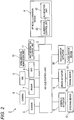
- FIG. 2 is a block diagram of the vehicle system 2.
- the vehicle system 2 includes a vehicle control unit 3, the illumination device 4, a sensor 5, a camera 6, a radar 7, a HMI (Human Machine Interface) 8, a GPS (Global Positioning System) 9, a wireless communication unit 10 (the first wireless communication unit), and a map information storage 11.
- the vehicle system 2 includes a steering actuator 12, a steering device 13, a brake actuator 14, a brake device 15, an accelerator actuator 16, and an accelerator device 17.
- the vehicle control unit 3 is configured to control travelling of the vehicle 1.
- the vehicle control unit 3 is configured by, for example, an electronic control unit (ECU).
- the electronic control unit includes a microcontroller having a processor and a memory, and other electronic circuits (for example, transistors, and the like).
- the processor is, for example, a CPU (Central Processing Unit), an MPU (Micro Processing Unit) and/or a GPU (Graphics Processing Unit).
- the memory includes a ROM (Read Only Memory) in which diverse vehicle control programs (for example, an artificial intelligence (AI) program for automatic driving, and the like) are stored, and a RAM (Random Access Memory) in which diverse vehicle control data is temporarily stored.
- the processor is configured to develop, on the RAM, a program designated from the diverse vehicle control programs stored in the ROM and to execute a variety of processes in cooperation with the RAM.
- the illumination device 4 includes the illumination unit 42 and the illumination control unit 43.
- the illumination unit 42 includes one or more light emitting elements such as LEDs (Light Emitting Diodes) or laser and is configured to irradiate light toward the outside of the vehicle 1.
- the illumination control unit 43 is configured by an electronic control unit (ECU).
- the illumination control unit 43 is electrically connected to a power supply (not shown), and includes a microcontroller having a processor such as a CPU and a GPU and a memory such as a ROM and a RAM, and other electronic circuits (for example, a drive circuit such as an LED driver).
- the vehicle control unit 3 and the illumination control unit 43 are provided as separate components but may be integrally configured.
- the illumination control unit 43 and the vehicle control unit 3 may be configured by a single electronic control unit.
- the illumination control unit 43 is configured to control the illumination unit 42 based on an illumination control signal transmitted from another vehicle including an illumination unit, such that an illumination state of the illumination unit 42 corresponds to an illumination state of the illumination unit of the other vehicle.
- the illumination control unit 43 may be configured to control the illumination unit 42 to blink in synchronization with the illumination unit of the other vehicle.
- the illumination control unit 43 may be configured to control the illumination unit 42 such that an illumination color of the illumination unit 42 corresponds to an illumination color of the illumination unit of the other vehicle.
- the sensor 5 includes an acceleration sensor, a speed sensor, a gyro sensor, and the like.
- the sensor 5 is configured to detect a travelling condition of the vehicle 1 and to output travelling condition information to the vehicle control unit 3.
- the sensor 5 may further include a seating sensor configured to detect whether a driver is sitting on a driver seat, a face direction sensor configured to detect a direction of a driver's face, an external weather sensor configured to detect an external weather condition, a passenger detection sensor configured to detect whether there is a passenger in a vehicle, and the like.
- the camera 6 is, for example, a camera including an imaging device such as a CCD (Charge-Coupled Device) and CMOS (complementary MOS).
- the radar 7 is a millimeter wave radar, a microwave radar, a laser radar, or the like.
- the camera 6 and/or the radar 7 are configured to detect surrounding environments (other vehicles, pedestrians, road shapes, traffic signs, obstacles, and the like) of the vehicle 1 and to output surrounding environment information to the vehicle control unit 3.
- the HMI 8 includes an input unit configured to receive an input operation from a driver and an output unit configured to output the travelling information and the like to the driver.
- the input unit includes a steering wheel, an accelerator pedal, a brake pedal, a driving mode changeover switch for switching the driving mode of the vehicle 1, and the like.
- the output unit is a display for displaying diverse travelling information.
- the GPS 9 is configured to acquire current position information of the vehicle 1 and to output the acquired current position information to the vehicle control unit 3.
- the wireless communication unit 10 is configured to receive information (for example, traveling information, and the like) relating to other vehicles around the vehicle 1 from the other vehicles and to transmit information (for example, traveling information, and the like) relating to the vehicle 1 to the other vehicles (inter-vehicle communication). Also, the wireless communication unit 10 is configured to receive an illumination control signal from a traffic infrastructure equipment. Also, the wireless communication unit 10 is configured to receive infrastructure information from the traffic infrastructure equipment and to transmit the traveling information of the vehicle 1 to the traffic infrastructure equipment (road-to-vehicle communication). The vehicle 1 may be configured to perform communication with the other vehicle and the traffic infrastructure equipment directly or via an access point.
- the map information storage 11 is an external storage device such as a hard disk drive in which map information is stored, and is configured to output the map information to the vehicle control unit 3.
- the vehicle control unit 3 automatically generates at least one of a steering control signal, an accelerator control signal and a brake control signal, based on the travelling condition information, the surrounding environment information, the current position information, the map information, and the like.
- the steering actuator 12 is configured to receive the steering control signal from the vehicle control unit 3 and to control the steering device 13 based on the received steering control signal.
- the brake actuator 14 is configured to receive the brake control signal from the vehicle control unit 3 and to control the brake device 15 based on the received brake control signal.
- the accelerator actuator 16 is configured to receive the accelerator control signal from the vehicle control unit 3 and to control the accelerator device 17 based on the received accelerator control signal. In this way, in the automatic driving mode, the travelling of the vehicle 1 is automatically controlled by the vehicle system 2.
- the vehicle control unit 3 when the vehicle 1 travels in a manual driving mode, the vehicle control unit 3 generates a steering control signal, an accelerator control signal and a brake control signal in conformity with a manual operation of a driver on the accelerator pedal, the brake pedal and the steering wheel.
- the steering control signal, the accelerator control signal and the brake control signal are generated by the manual operation of the driver, so that the travelling of the vehicle 1 is controlled by the driver.
- the driving mode includes an automatic driving mode and a manual driving mode.
- the automatic driving mode includes a full-automatic driving mode, an advanced driving support mode, and a driving support mode.
- the vehicle system 2 In the full-automatic driving mode, the vehicle system 2 is configured to automatically perform all of the travelling controls of the steering control, the brake control and the accelerator control, and the driver is not in a state where it is possible to drive the vehicle 1.
- the vehicle system 2 In the advanced driving support mode, the vehicle system 2 is configured to automatically perform all of the travelling controls of the steering control, the brake control and the accelerator control, and the driver does not drive the vehicle 1 although the driver is in a state where it is possible to drive the vehicle 1.
- the vehicle system 2 In the driving support mode, the vehicle system 2 is configured to automatically perform a part of the travelling controls of the steering control, the brake control and the accelerator control, and the driver drives the vehicle 1 under the driving support of the vehicle system 2.
- the vehicle system 2 In the manual driving mode, the vehicle system 2 is configured not to automatically perform the travelling controls, and the driver drives the vehicle 1 without the driving support of the vehicle system 2.
- the driving mode of the vehicle 1 may be switched by operating a driving mode changeover switch.
- the vehicle control unit 3 is configured to switch the driving mode of the vehicle 1 among the four driving modes (the full-automatic driving mode, the advanced driving support mode, the driving support mode, and the manual driving mode) in accordance with a driver's operation on the driving mode changeover switch.
- the driving mode of the vehicle 1 may be automatically switched based on information relating to a travel-allowed section where travelling of an automatic driving vehicle is allowed or a travel-prohibited section where the travelling of the automatic driving vehicle is prohibited or information relating to the external weather condition.
- the vehicle control unit 3 is configured to switch the driving mode of the vehicle 1, based on such information.
- the driving mode of the vehicle 1 may be automatically switched by using a seating sensor, a face direction sensor, or the like.
- the vehicle control unit 3 is configured to switch the driving mode of the vehicle 1, based on an output signal from the seating sensor or the face direction sensor.
- FIG. 3 depicts a configuration of the illumination control system 100 according to the embodiment.
- the illumination control system 100 includes a vehicle 1A (second vehicle) and a vehicle 1B (first vehicle) capable of traveling in the automatic driving mode.
- the vehicle 1A is a master vehicle
- the vehicle 1B is a slave vehicle.
- the master vehicle is a vehicle configured to transmit an illumination control signal
- the slave vehicle is a vehicle configured to receive the illumination control signal.
- Vehicle systems 2A, 2B of the vehicles 1A, 1B have the same configuration as the vehicle system 2 of the vehicle 1 shown in FIG. 2 .
- a wireless communication unit 10A and a wireless communication unit 10B have the same configuration as the wireless communication unit 10 shown in FIG. 2 .
- Vehicle control units 3A, 3B have the same configuration as the vehicle control unit 3 shown in FIG. 2 .
- the vehicle control unit 3A includes a control signal generation unit 30A configured to generate an illumination control signal
- the vehicle control unit 3B includes a control signal generation unit 30B configured to generate an illumination control signal.
- the control signal generation unit 30B since the vehicle 1B is a slave vehicle, the control signal generation unit 30B does not generate an illumination control signal.
- the control signal generation unit 30B when the vehicle 1B is a master vehicle, the control signal generation unit 30B generates an illumination control signal.
- Vehicle illumination devices 4A, 4B have the same configuration as the illumination device 4 shown in FIG. 2 .
- an illumination control unit 43A (the second illumination control unit) and an illumination control unit 43B (the first illumination control unit) have the same configuration as the illumination control unit 43 shown in FIG. 2 .
- An illumination unit 42A (the second illumination unit) and an illumination unit 42B (the first illumination unit) have the same configuration as the illumination unit 42 shown in FIG. 2 .
- the two vehicles 1A, 1B are shown.
- the number of the vehicles is not particularly limited.
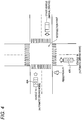
- FIG. 4 illustrates a situation where an illumination state of the illumination unit 42A of the vehicle 1A and an illumination state of the illumination unit 42B of the vehicle 1B correspond to each other at an intersection point.
- the vehicles 1A, 1B exist in the vicinity of the intersection point, the vehicle 1A is a master vehicle and the vehicle 1B is a slave vehicle.
- the wireless communication unit 10B can receive the illumination control signal, the traveling information of the vehicle 1A and the like from the wireless communication unit 10A.
- the wireless communication unit 10B can receive the illumination control signal, the traveling information of the vehicle 1A and the like from the wireless communication unit 10A.
- FIG. 5 is a sequence diagram for illustrating an example of the operation of the illumination control system 100.
- the vehicle 1A appears in the vicinity of the intersection point temporally earlier than the vehicle 1B and the vehicle 1A becomes a master vehicle.
- the vehicle 1A first detects the vehicle 1B (step S1).
- the vehicle 1A may detect that the vehicle 1A exists in the vicinity of the intersection point based on the surrounding environment information and the map information, and then detect the vehicle 1B by using a camera or a sensor.
- the vehicle 1A may detect the vehicle 1B by receiving information, which indicates that there is the vehicle 1B, from the traffic infrastructure equipment arranged in the vicinity of the intersection point. Also, the vehicle 1A may detect the vehicle 1B by broadcasting a beacon toward an outside with a predetermined period and receiving a response signal to the broadcast beacon from the vehicle 1B. In the meantime, when the vehicle 1B exists within the predetermined range from the vehicle 1A, the vehicle 1B can receive the beacon broadcast from the vehicle 1A.
- step S2 the vehicle 1A establishes wireless communication connection with the vehicle 1B.
- the vehicle 1A and the vehicle 1B may directly perform communication with each other in an ad hook mode.
- wireless communication connection is established between the vehicle 1A and the vehicle 1B by a passive scan method or an active scan method.
- the wireless communication unit 10A transmits the beacon including information relating to the wireless communication connection to the vehicle 1B with a predetermined period, in accordance with a command of the vehicle control unit 3A.
- the wireless communication unit 10B receives the beacon transmitted from the vehicle 1A.
- the vehicle 1A establishes wireless communication connection with the vehicle 1B, through authentication/association between the vehicle 1A and the vehicle 1B.
- the vehicle 1A and the vehicle 1B may perform communication with each other via the traffic infrastructure equipment having an access point function.
- the vehicle 1A transmits, to the vehicle 1B, the traveling information of the vehicle 1A (for example, the traveling information indicative of left turn/right turn/straight advancing at the intersection point), for example.
- the wireless communication unit 10A transmits the traveling information of the vehicle 1A to the vehicle 1B, in accordance with a command of the vehicle control unit 3A.
- the wireless communication unit 10B of the vehicle 1B receives the traveling information of the vehicle 1A from the vehicle 1A (step S4).
- the vehicle 1B may transmit the traveling information of the vehicle 1B to the vehicle 1A, and the vehicle 1A may receive the traveling information of the vehicle 1B from the vehicle 1B.
- the vehicle control unit 3B automatically controls the traveling of the vehicle 1B, based on the surrounding environment information and the like acquired by the vehicle system 2B and the traveling information of the vehicle 1A.
- the vehicle control unit 3A automatically controls the traveling of the vehicle 1A, based on the surrounding environment information and the like acquired by the vehicle system 2A and the traveling information of the vehicle 1B. In this way, the vehicle 1A (1B) acquires the traveling information of the vehicle 1B (1A), so that it is possible to execute the more correct automatic driving control of the vehicle 1A(1B).
- control signal generation unit 30A generates an illumination control signal indicative of an illumination state of the illumination unit 42A (step S5).
- the wireless communication unit 10A transmits the generated illumination control signal to the vehicle 1B, in accordance with a command of the vehicle control unit 3A (step S6).
- the wireless communication unit 10B of the vehicle 1B receives the illumination control signal from the vehicle 1A (step S7). Then, the illumination control unit 43B controls the illumination unit 42B such that an illumination state of the illumination unit 42B corresponds to an illumination state of the illumination unit 42A, based on the received illumination control signal (step S8). For example, when the illumination unit 42A is controlled by the illumination control unit 43A to blink with a predetermined period, the illumination control unit 43B may control the illumination unit 42B to blink in synchronization with the illumination unit 42A, based on the illumination control signal indicative of blinking control information of the illumination unit 42A.
- the illumination control unit 43B may control the illumination unit 42B such that an illumination color of the illumination unit 42B corresponds to the illumination color of the illumination unit 42A, based on the illumination control signal indicative of the illumination color of the illumination unit 42A. Also, at a point of time at which the wireless communication connection is established between the vehicle 1A and the vehicle 1B, the illumination control unit 43A may blink the illumination unit 42A or change the illumination color of the illumination unit 42A from a first illumination color to a second illumination color. In this way, the series of illumination control processing is executed.
- the vehicle 1A is set as the master vehicle, and the vehicle 1B is set as the slave vehicle.
- the illumination control is executed between the vehicles by a similar method.
- the control signal generation unit 30B of the vehicle control unit 3B generates the illumination control signal.
- the vehicle 1A transmits the traveling information of the vehicle 1A to the vehicle 1B.
- the vehicle 1A may be configured to transmit, to the vehicle 1B, predetermined information other than the traveling information.
- the control signal generation unit 30A may generate a traveling control signal for controlling the traveling of the vehicle 1B, and the wireless communication unit 10A may transmit the generated traveling control signal to the vehicle 1B.
- the vehicle control unit 3B executes the automatic traveling control at the intersection point, based on the traveling control signal transmitted from the vehicle 1A.
- the vehicle 1A may establish wireless communication connection with an electronic device (for example, a portable phone, a smart phone, a tablet, a wearable device and the like) carried by a pedestrian P1 in the vicinity of the intersection point.
- the vehicle 1A (the wireless communication unit 10A) may establish wireless communication connection with the electronic device carried by the pedestrian (hereinafter, simply referred to as the electronic device) and then transmit the illumination control signal indicative of the illumination state of the illumination unit 42A to the electronic device.
- a control unit of the electronic device may control a display unit (or a light-emitting unit) of the electronic device such that an illumination state of the display unit (or the light-emitting unit) of the electronic device corresponds to the illumination state of the illumination unit 42A, in accordance with the received illumination control signal.
- the illumination states of the illumination units 42A, 42B and the illumination state of the display unit (or the light-emitting unit) of the electronic device may be associated with each other.
- a vehicle that has first reached in the vicinity of the intersection point may be set as a master vehicle, and a vehicle that has later reached in the vicinity of the intersection point may be set as a slave vehicle.
- the vehicle 1A that has reached in the vicinity of the intersection point outputs a beacon, which indicates that the vehicle 1A has reached in the vicinity of the intersection point, toward an outside. Then, when the vehicle 1A receives an ACK beacon to the beacon from the other vehicle, the vehicle 1A (the vehicle control unit 3A) determines that there is the other vehicle that has reached in the vicinity of the intersection point earlier than the vehicle 1A, and waits for a communication connection request from the other vehicle (in this way, the vehicle control unit 3A determines that the vehicle 1A is a slave vehicle).
- the vehicle 1A determines that there is no other vehicle in the vicinity of the intersection point, and waits until the other vehicle appears in the vicinity of the intersection point (in this way, the vehicle control unit 3A determines that the vehicle 1A is a master vehicle).
- the vehicle 1A executes the series of processing shown in FIG. 5 .
- the vehicle 1A (master vehicle) may instruct the vehicle 1B, which has reached the intersection point later than the vehicle 1A, to be a master vehicle and then stop the transmission of the illumination control signal to the vehicle 1B.
- the traffic infrastructure equipment arranged in the vicinity of the intersection point may be used. For example, when the vehicle 1A reaches in the vicinity of the intersection point, the traffic infrastructure equipment detects the vehicle 1A. When the traffic infrastructure equipment determines that there is no vehicle except the vehicle 1A in the vicinity of the intersection point, the traffic infrastructure equipment transmits a signal, which indicates that the vehicle 1A is a master vehicle, to the vehicle 1A. On the other hand, when the traffic infrastructure equipment determines that there is a vehicle in the vicinity of the intersection point, in addition to the vehicle 1A, the traffic infrastructure equipment transmits a signal, which indicates that the vehicle 1A is a slave vehicle, to the vehicle 1A.
- the vehicle 1A master vehicle
- the vehicle 1A may notify the traffic infrastructure equipment that the vehicle 1A has passed the intersection point, and then stop the transmission of the illumination control signal to the vehicle 1B.
- the vehicle 1B may notify the traffic infrastructure equipment that the vehicle 1B has passed the intersection point.
- the illumination device 4B capable of presenting the information, which indicates that the vehicle 1A and the vehicle 1B are performing communication with each other, toward an outside such as a pedestrian PI, and the like.
- the illumination device 4B can visualize a state of inter-vehicle communication between the vehicles capable of traveling in the automatic driving mode by the illumination device 4B.
- the pedestrian P1 and the like can check safety of the vehicles 1A, 1B by seeing the information indicating that the vehicle 1B is performing communication with the vehicle 1A, the pedestrian can cross in relief a crosswalk and the like.
- a driver of the other vehicle can check safety of the vehicles 1A, 1B by seeing the information indicating that the vehicle 1A and the vehicle 1B are performing communication with each other, the driver can pass in relief the intersection point.
- the illumination control unit 43B controls the illumination unit 42B to blink in synchronization with the illumination unit 42A
- the pedestrian P1 can perceive that the vehicle 1B is performing communication with the vehicle 1A by seeing the situation where the illumination unit 42B is blinking in synchronization with the illumination unit 42A.
- the illumination control unit 43B controls the illumination unit 42B such that the illumination color of the illumination units 42B corresponds to the illumination color of the illumination units 42A
- the pedestrian P1 can perceive that the vehicle 1B is performing communication with the vehicle 1A by seeing the situation where the illumination color of the illumination unit 42B corresponds to the illumination color of the illumination unit 42A.
- the wireless communication unit 10B can receive the illumination control signal from the wireless communication unit 10A.
- the vehicle 1B existing within the predetermined range from the vehicle 1A can present the information, which indicates that the vehicle 1B is performing communication with the vehicle 1A, toward the pedestrian P1.
- the wireless communication unit 10B may receive the illumination control signal from the wireless communication unit 10A.
- the vehicle 1B existing in the vicinity of the intersection point can present the information, which indicates that the vehicle 1B is performing communication with the vehicle 1A, toward the outside such as the pedestrian P1 and the like.
- the pedestrian P1 in the vicinity of the intersection point can check the safety of the vehicles 1A, 1B by seeing the information and can cross in relief the crosswalk.
- the pedestrian P1 can visually recognize that the vehicles 1A, 1B and the electronic device are performing communication with each other, and can clearly check the safety of the vehicles 1A, 1B.
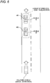
- FIG. 6 illustrates a situation where an illumination state of the illumination unit 42A of the vehicle 1A belonging to a group of vehicles G traveling in a row traveling mode and an illumination state of the illumination unit 42B of the vehicle 1B correspond to each other.
- FIG. 7 is a sequence diagram for illustrating an example of an operation of the illumination control system 100 that is implemented by the group of vehicles G traveling in the row traveling mode.
- a following vehicle executes the automatic traveling control, based on a row traveling control signal transmitted from a leading vehicle.
- the following vehicle may be configured to execute the automatic traveling control, based on only the row traveling control signal transmitted from the leading vehicle or may be configured to execute the automatic traveling control, based on the transmitted row traveling control signal, the surrounding environment information acquired by a camera and a radar of the following vehicle, and the like.
- a leading vehicle is a master vehicle
- a following vehicle except the leading vehicle is a slave vehicle.
- the vehicle 1A is a leading vehicle of a group of vehicles G
- the vehicle 1B is a following vehicle of the group of vehicles G.
- the vehicle 1A may travel in the automatic driving mode or in the manual driving mode.
- the number of vehicles belonging to the group of vehicles G may be three or more.
- the vehicle control unit 3A of the vehicle 1A which is the leading vehicle, generates a row traveling control signal. Then, the wireless communication unit 10A transmits the generated row traveling control signal to the vehicle 1B, in accordance with a command of the vehicle control unit 3A.
- the wireless communication unit 10B of the vehicle 1B which is the following vehicle, receives the row traveling control signal, and then the vehicle control unit 3B automatically controls the traveling of the vehicle 1B, based on the row traveling control signal.
- the vehicle 1A and the vehicle 1B may directly perform communication with each other in an ad hook mode.
- the vehicle 1B transmits a row request signal to the vehicle 1A (the wireless communication unit 10A) (step S10).
- the vehicle control unit 3A determines whether it is possible to implement a row traveling in which the vehicle 1A is a leading vehicle.
- the wireless communication unit 10A transmits a row-possible signal to the vehicle 1B (step S12).
- the vehicle control unit 3B may display notice information, which indicates that the driving mode of the vehicle 1B is a row traveling mode, on a display mounted to the vehicle 1B.
- the wireless communication unit 10A transmits the generated row traveling control signal to the vehicle 1B (step S14).
- the vehicle control unit 3B executes the automatic traveling control, based on the received row traveling control signal. Accordingly, the driving mode of the vehicle 1B becomes the row traveling mode.
- the wireless communication unit 10A transmits the illumination control signal to the vehicle 1B (step S17).
- the illumination control unit 43B controls the illumination unit 42B such that the illumination state of the illumination unit 42B corresponds to the illumination state of the illumination unit 42A, based on the illumination control signal (step S19).
- the illumination control unit 43B may control the illumination unit 42B to blink in synchronization with the illumination unit 42A or may control the illumination unit 42B such that the illumination color of the illumination unit 42B corresponds to the illumination color of the illumination unit 42A. In this way, the series of illumination control processing is executed.
- a following vehicle which is traveling immediately after the leading vehicle, becomes a new leading vehicle (master vehicle), and may transmit the row traveling control signal and the illumination control signal to a following vehicle. Also, at a point of time at which the leading vehicle leaves the row, the leading vehicle may stop the transmission of the row traveling control signal and the illumination control signal to a following vehicle. In the meantime, when a following vehicle leaves the row, the following vehicle may notify the leading vehicle that the following vehicle leaves the row, and then the leading vehicle stops the transmission of the row traveling control signal and the illumination control signal to the following vehicle.
- the illumination control system 100 capable of presenting the information, which indicates that the leading vehicle and the following vehicle belonging to the group of vehicles G traveling in the row traveling mode are performing communication with each other, toward an outside such as a following vehicle (manual driving mode), a pedestrian P1 and the like.
- a following vehicle manual driving mode
- a pedestrian P1 pedestrian
- the driving mode of the vehicle includes the full-automatic driving mode, the advanced driving support mode, the driving support mode, and the manual driving mode.
- the driving mode of the vehicle should not be limited to the four modes.
- the classification of the driving mode of the vehicle may be appropriately changed, in accordance with laws or rules relating to the automatic driving in each country.
- the definitions of "the full-automatic driving mode", “the advanced driving support mode” and “the driving support mode” described in the embodiment are just examples, and can be appropriately changed, in accordance with laws or rules relating to the automatic driving in each country.
Landscapes
- Engineering & Computer Science (AREA)
- Mechanical Engineering (AREA)
- Physics & Mathematics (AREA)
- General Physics & Mathematics (AREA)
- Automation & Control Theory (AREA)
- Transportation (AREA)
- Remote Sensing (AREA)
- Radar, Positioning & Navigation (AREA)
- Aviation & Aerospace Engineering (AREA)
- Lighting Device Outwards From Vehicle And Optical Signal (AREA)
- Traffic Control Systems (AREA)
- Business, Economics & Management (AREA)
- Health & Medical Sciences (AREA)
- Artificial Intelligence (AREA)
- Evolutionary Computation (AREA)
- Game Theory and Decision Science (AREA)
- Medical Informatics (AREA)
Abstract
Description
- The present disclosure relates to a vehicle illumination device. In particular, the present disclosure relates to a vehicle illumination device provided to a vehicle capable of traveling in an automatic driving mode. Also, the present disclosure relates to a vehicle having a vehicle illumination device, and an illumination control system including the vehicle.
- Currently, research on an automatic driving technique of an automobile has been actively conducted in each country, and each country is considering the legislation so as to enable a vehicle (hereinafter, a "vehicle" refer to an automobile) to travel in an automatic driving mode on public roads. Here, in the automatic driving mode, a vehicle system automatically controls travelling of a vehicle. Specifically, in the automatic driving mode, the vehicle system performs at least one of a steering control (control a travelling direction of the vehicle), a brake control and an accelerator control (control of braking and acceleration/deceleration of the vehicle) based on various information obtained from a camera, a sensor, a radar and the like. On the other hand, in a manual driving mode to be described later, a driver controls the travelling of the vehicle, as in most of conventional vehicles. Specifically, in the manual driving mode, the travelling of the vehicle is controlled in conformity with a driver's operation (a steering operation, a braking operation, and an accelerator operation), and the vehicle system does not automatically perform the steering control, the brake control and the accelerator control. Meanwhile, the driving mode of the vehicle is not a concept existing only in some vehicles but a concept existing in all vehicles including conventional vehicles having no automatic driving function. For example, the driving mode of the vehicle is classified in accordance with a vehicle control method or the like.
- Thus, in the future, it is expected that vehicles travelling in the automatic driving mode (hereinafter, appropriately referred to as "automatic driving vehicle") and vehicles travelling in the manual driving mode (hereinafter, appropriately referred to as "manual driving vehicle") coexist on public roads. Particularly, in a situation where the vehicles travelling in the automatic driving mode and the vehicles travelling in the manual driving mode coexist, it is preferable that a state of inter-vehicle communication between one automatic driving vehicle and the other automatic driving vehicle is presented to an outside, from a standpoint of safety.
-
Patent Document 1 discloses an automatic follow-up travelling system in which a following vehicle can automatically follow a preceding vehicle. In the automatic follow-up travelling system, each of the preceding vehicle and the following vehicle has a display device, character information for preventing the other vehicle from intruding between the preceding vehicle and the following vehicle is displayed on the display device of the preceding vehicle, and character information indicative of the automatic follow-up travelling mode is displayed on the display device of the following vehicle. - Patent Document 1:
JP-A-H09-277887 -
Patent Document 1 does not consider a vehicle illumination device and an illumination control system capable of presenting information, which indicates that one automatic driving vehicle is performing communication with the other automatic driving vehicle under specific situations (for example, a situation at an intersection point), toward an outside such as a pedestrian and the like. - An object of the present disclosure is to provide a vehicle illumination device capable of presenting information, which indicates that one automatic driving vehicle is performing communication with the other automatic driving vehicle, toward an outside such as a pedestrian and the like. Another object of the present disclosure is to provide a vehicle having the vehicle illumination device and an illumination control system including the vehicle.
- A vehicle illumination device according to an aspect of the present disclosure is a vehicle illumination device provided to a vehicle capable of traveling in an automatic driving mode. The vehicle illumination device includes:
- a first illumination unit configured to irradiate light toward an outside of the vehicle; and
- a first illumination control unit configured to control the first illumination unit based on an illumination control signal transmitted from another vehicle capable of traveling in the automatic driving mode and including the second illumination unit, such that an illumination state of the first illumination unit corresponds to an illumination state of a second illumination unit.
- According to the above configuration, it is possible to provide the vehicle illumination device capable of presenting information, which indicates that a host vehicle capable of traveling in the automatic driving mode is performing communication with the other vehicle capable of traveling in the automatic driving mode, toward an outside such as a pedestrian and the like. In other words, it is possible to visualize a state of inter-vehicle communication between the vehicles capable of traveling in the automatic driving mode by the vehicle illumination device. For example, since the pedestrian and the like can check safety of the host vehicle and the other vehicle by seeing the information indicating that the host vehicle is performing communication with the other vehicle, the pedestrian can cross in relief a crosswalk and the like. Also, since a driver of a separate vehicle can check safety of the host vehicle and the other vehicle by seeing the information indicating that the host vehicle is performing communication with the other vehicle, the driver can pass in relief an intersection point or overtake in relief the host vehicle and the other vehicle.
- Also, the first illumination control unit may be configured to control the first illumination unit to blink in synchronization with the second illumination unit.
- According to the above configuration, the pedestrian and the like can perceive that the host vehicle is performing communication with the other vehicle by seeing a situation where the first illumination unit is blinking in synchronization with the second illumination unit.
- Also, the first illumination control unit may be configured to control the first illumination unit such that an illumination color of the first illumination unit corresponds to an illumination color of the second illumination unit.
- According to the above configuration, the pedestrian and the like can perceive that the host vehicle is performing communication with the other vehicle by seeing a situation where the illumination color of the first illumination unit corresponds to the illumination color of the second illumination unit.
- Also, a vehicle capable of traveling in an automatic driving mode may be provided which includes the vehicle illumination device, a first wireless communication unit configured to receive the illumination control signal and a vehicle control unit configured to control traveling of the vehicle.
- According to the above configuration, it is possible to provide the vehicle capable of presenting information, which indicates that the host vehicle capable of traveling in the automatic driving mode is performing communication with the other vehicle capable of traveling in the automatic driving mode, toward an outside such as a pedestrian and the like.
- An illumination control system according to an embodiment of the present disclosure includes:
- a second vehicle capable of traveling in an automatic driving mode and including:
- a second illumination unit configured to irradiate light toward an outside;
- a second illumination control unit configured to control the second illumination unit;
- a control signal generation unit configured to generate an illumination control signal; and
- a second wireless communication unit configured to transmit the illumination control signal; and
- a first vehicle capable of traveling in the automatic driving mode and including:
- a first wireless communication unit configured to receive the illumination control signal;
- a first illumination unit configured to irradiate light toward the outside; and
- a first illumination control unit configured to control the first illumination unit based on the illumination control signal such that an illumination state of the first illumination unit corresponds to an illumination state of the second illumination unit.
- According to the above configuration, it is possible to provide the illumination control system capable of presenting information, which indicates that the first vehicle capable of traveling in the automatic driving mode is performing communication with the second vehicle capable of traveling in the automatic driving mode, toward an outside such as a pedestrian and the like.
- Also, when the first vehicle exists within a predetermined range from the second vehicle, the first wireless communication unit may be able to receive the illumination control signal from the second wireless communication unit.
- According to the above configuration, the first vehicle existing within the predetermined range from the second vehicle can present information, which indicates that the first vehicle is performing communication with the second vehicle, toward an outside such as a pedestrian and the like. Accordingly, the pedestrian and the like in the vicinity of the first vehicle or the second vehicle can check the safety of the first vehicle and the second vehicle by seeing the information.
- Also, when the first vehicle and the second vehicle exist in the vicinity of an intersection point, the first wireless communication unit may be able to receive the illumination control signal from the second wireless communication unit.
- According to the above configuration, the first vehicle existing in the vicinity of the intersection point can present information, which indicates that the first vehicle is performing communication with the second vehicle, toward an outside such as a pedestrian and the like. Accordingly, the pedestrian and the like in the vicinity of the intersection point can check the safety of the first vehicle and the second vehicle by seeing the information, and can cross in relief a crosswalk and the like.
- Also, the second vehicle may be a vehicle that appears in the vicinity of the intersection point temporally earlier than the first vehicle.
- According to the above configuration, a vehicle that appears temporally earliest in the vicinity of the intersection point is a master vehicle (second vehicle), and a vehicle that appears in the vicinity of the intersection point temporally later than the master vehicle is a slave vehicle (first vehicle).
- Also, the first vehicle and the second vehicle may belong to a group of vehicles traveling in a row traveling mode, and
the second vehicle may be a leading vehicle of the group of vehicles and the first vehicle may be a following vehicle of the group of vehicles. - According to the above configuration, a leading vehicle of the group of vehicles traveling in the row traveling mode is a master vehicle (second vehicle), and a following vehicle except the leading vehicle is a slave vehicle (first vehicle). Also, it is possible to provide the illumination control system capable of presenting information, which indicates that the leading vehicle and following vehicle belonging to the group of vehicles traveling in the row traveling mode are performing communication with each other, toward an outside. For example, since a driver of a following vehicle traveling in a manual driving mode behind the group of vehicles can visually recognize that the group of vehicles is traveling in the row traveling mode, the driver can overtake in relief the group of vehicles.
- According to the present disclosure, it is possible to provide the vehicle illumination device capable of presenting the information, which indicates that one automatic driving vehicle is performing communication with the other automatic driving vehicle, toward an outside such as a pedestrian, and the like.
-
-
FIG. 1A is a plan view of a vehicle in which a vehicle illumination device according to an embodiment of the present invention is mounted, andFIG. 1B is a left side view of the vehicle shown inFIG. 1A . -
FIG. 2 is a block diagram of a vehicle system including the vehicle illumination device according to the embodiment of the present invention. -
FIG. 3 depicts a configuration of an illumination control system according to the embodiment of the present invention. -
FIG. 4 illustrates a situation where an illumination state of an illumination unit of one vehicle and an illumination state of an illumination unit of the other vehicle correspond to each other at an intersection point. -
FIG. 5 is a sequence diagram for illustrating an example of an operation of the illumination control system. -
FIG. 6 illustrates a situation where an illumination state of the illumination unit of one vehicle belonging to a group of vehicles traveling in a row traveling mode and an illumination state of the illumination unit of the other vehicle correspond to each other. -
FIG. 7 is a sequence diagram for illustrating an example of an operation of an illumination control system that is implemented by a group of vehicles G traveling in the row traveling mode. - Hereinafter, an embodiment of the present disclosure (hereinafter, referred to as "the embodiment") will be described with reference to the drawings. Meanwhile, in the below, for the sake of convenience of description, the description of members having the same reference numerals as those already described in the description of the embodiment will be omitted. Also, for the sake of convenience of description, dimensions of the respective members shown in the drawings may be different from actual dimensions of the respective members.
- Also, in the description of the embodiment, for the sake of convenience of description, "the right and left direction", "the front and rear direction" and "the vertical direction" will be appropriately mentioned. The directions are relative directions set with respect to a
vehicle 1 shown inFIG. 1 . Here, "the vertical direction" is a direction including "the upward direction" and "the downward direction". "the front and rear direction" is a direction including "the forward direction" and "the rearward direction". "the right and left direction" is a direction including "the leftward direction" and "the rightward direction". - A
vehicle illumination device 4 according to the embodiment (hereinafter, simply referred to as "illumination device 4") is described.FIG. 1A is a plan view of thevehicle 1, andFIG. 1B is a left side view of thevehicle 1. Thevehicle 1 is a vehicle capable of traveling in an automatic driving mode, and includes theillumination device 4. Theillumination device 4 includes anillumination unit 42, and an illumination control unit 43 (refer toFIG. 2 ). Theillumination unit 42 is arranged on avehicle body roof 100A of thevehicle 1, and is configured to irradiate light toward an outside of thevehicle 1. In particular, theillumination unit 42 is configured to irradiate light over an entire circumference (360°) of theillumination unit 42 in a horizontal direction. Here, the horizontal direction refers to a direction including the front and rear direction and the right and left direction. - Meanwhile, in the embodiment, the
single illumination unit 42 is arranged on thevehicle body roof 100A. However, the number, arrangement, shape and the like of theillumination unit 42 are not particularly limited. For example, the twoillumination units 42 of the fourillumination units 42 may be respectively arranged in aleft headlamp 20L and aright headlamp 20R, and theother illumination units 42 may be respectively arranged in a leftrear combination lamp 30L and a rightrear combination lamp 30R. Also, theillumination unit 42 may be arranged to surround aside surface 100B of thevehicle 1. - Subsequently, a
vehicle system 2 of thevehicle 1 is described with reference toFIG. 2. FIG. 2 is a block diagram of thevehicle system 2. As shown inFIG. 2 , thevehicle system 2 includes avehicle control unit 3, theillumination device 4, asensor 5, acamera 6, a radar 7, a HMI (Human Machine Interface) 8, a GPS (Global Positioning System) 9, a wireless communication unit 10 (the first wireless communication unit), and amap information storage 11. In addition, thevehicle system 2 includes asteering actuator 12, asteering device 13, abrake actuator 14, abrake device 15, anaccelerator actuator 16, and anaccelerator device 17. - The
vehicle control unit 3 is configured to control travelling of thevehicle 1. Thevehicle control unit 3 is configured by, for example, an electronic control unit (ECU). The electronic control unit includes a microcontroller having a processor and a memory, and other electronic circuits (for example, transistors, and the like). The processor is, for example, a CPU (Central Processing Unit), an MPU (Micro Processing Unit) and/or a GPU (Graphics Processing Unit). The memory includes a ROM (Read Only Memory) in which diverse vehicle control programs (for example, an artificial intelligence (AI) program for automatic driving, and the like) are stored, and a RAM (Random Access Memory) in which diverse vehicle control data is temporarily stored. The processor is configured to develop, on the RAM, a program designated from the diverse vehicle control programs stored in the ROM and to execute a variety of processes in cooperation with the RAM. - The
illumination device 4 includes theillumination unit 42 and theillumination control unit 43. Theillumination unit 42 includes one or more light emitting elements such as LEDs (Light Emitting Diodes) or laser and is configured to irradiate light toward the outside of thevehicle 1. Theillumination control unit 43 is configured by an electronic control unit (ECU). Theillumination control unit 43 is electrically connected to a power supply (not shown), and includes a microcontroller having a processor such as a CPU and a GPU and a memory such as a ROM and a RAM, and other electronic circuits (for example, a drive circuit such as an LED driver). In the embodiment, thevehicle control unit 3 and theillumination control unit 43 are provided as separate components but may be integrally configured. That is, theillumination control unit 43 and thevehicle control unit 3 may be configured by a single electronic control unit. Theillumination control unit 43 is configured to control theillumination unit 42 based on an illumination control signal transmitted from another vehicle including an illumination unit, such that an illumination state of theillumination unit 42 corresponds to an illumination state of the illumination unit of the other vehicle. For example, theillumination control unit 43 may be configured to control theillumination unit 42 to blink in synchronization with the illumination unit of the other vehicle. Also, theillumination control unit 43 may be configured to control theillumination unit 42 such that an illumination color of theillumination unit 42 corresponds to an illumination color of the illumination unit of the other vehicle. - The
sensor 5 includes an acceleration sensor, a speed sensor, a gyro sensor, and the like. Thesensor 5 is configured to detect a travelling condition of thevehicle 1 and to output travelling condition information to thevehicle control unit 3. Thesensor 5 may further include a seating sensor configured to detect whether a driver is sitting on a driver seat, a face direction sensor configured to detect a direction of a driver's face, an external weather sensor configured to detect an external weather condition, a passenger detection sensor configured to detect whether there is a passenger in a vehicle, and the like. - The
camera 6 is, for example, a camera including an imaging device such as a CCD (Charge-Coupled Device) and CMOS (complementary MOS). The radar 7 is a millimeter wave radar, a microwave radar, a laser radar, or the like. Thecamera 6 and/or the radar 7 are configured to detect surrounding environments (other vehicles, pedestrians, road shapes, traffic signs, obstacles, and the like) of thevehicle 1 and to output surrounding environment information to thevehicle control unit 3. - The
HMI 8 includes an input unit configured to receive an input operation from a driver and an output unit configured to output the travelling information and the like to the driver. The input unit includes a steering wheel, an accelerator pedal, a brake pedal, a driving mode changeover switch for switching the driving mode of thevehicle 1, and the like. The output unit is a display for displaying diverse travelling information. - The
GPS 9 is configured to acquire current position information of thevehicle 1 and to output the acquired current position information to thevehicle control unit 3. Thewireless communication unit 10 is configured to receive information (for example, traveling information, and the like) relating to other vehicles around thevehicle 1 from the other vehicles and to transmit information (for example, traveling information, and the like) relating to thevehicle 1 to the other vehicles (inter-vehicle communication). Also, thewireless communication unit 10 is configured to receive an illumination control signal from a traffic infrastructure equipment. Also, thewireless communication unit 10 is configured to receive infrastructure information from the traffic infrastructure equipment and to transmit the traveling information of thevehicle 1 to the traffic infrastructure equipment (road-to-vehicle communication). Thevehicle 1 may be configured to perform communication with the other vehicle and the traffic infrastructure equipment directly or via an access point. Themap information storage 11 is an external storage device such as a hard disk drive in which map information is stored, and is configured to output the map information to thevehicle control unit 3. - When the
vehicle 1 travels in an automatic driving mode, thevehicle control unit 3 automatically generates at least one of a steering control signal, an accelerator control signal and a brake control signal, based on the travelling condition information, the surrounding environment information, the current position information, the map information, and the like. The steeringactuator 12 is configured to receive the steering control signal from thevehicle control unit 3 and to control thesteering device 13 based on the received steering control signal. Thebrake actuator 14 is configured to receive the brake control signal from thevehicle control unit 3 and to control thebrake device 15 based on the received brake control signal. Theaccelerator actuator 16 is configured to receive the accelerator control signal from thevehicle control unit 3 and to control theaccelerator device 17 based on the received accelerator control signal. In this way, in the automatic driving mode, the travelling of thevehicle 1 is automatically controlled by thevehicle system 2. - On the other hand, when the
vehicle 1 travels in a manual driving mode, thevehicle control unit 3 generates a steering control signal, an accelerator control signal and a brake control signal in conformity with a manual operation of a driver on the accelerator pedal, the brake pedal and the steering wheel. In this way, in the manual driving mode, the steering control signal, the accelerator control signal and the brake control signal are generated by the manual operation of the driver, so that the travelling of thevehicle 1 is controlled by the driver. - Subsequently, the driving mode of the
vehicle 1 is described. The driving mode includes an automatic driving mode and a manual driving mode. The automatic driving mode includes a full-automatic driving mode, an advanced driving support mode, and a driving support mode. In the full-automatic driving mode, thevehicle system 2 is configured to automatically perform all of the travelling controls of the steering control, the brake control and the accelerator control, and the driver is not in a state where it is possible to drive thevehicle 1. In the advanced driving support mode, thevehicle system 2 is configured to automatically perform all of the travelling controls of the steering control, the brake control and the accelerator control, and the driver does not drive thevehicle 1 although the driver is in a state where it is possible to drive thevehicle 1. In the driving support mode, thevehicle system 2 is configured to automatically perform a part of the travelling controls of the steering control, the brake control and the accelerator control, and the driver drives thevehicle 1 under the driving support of thevehicle system 2. On the other hand, in the manual driving mode, thevehicle system 2 is configured not to automatically perform the travelling controls, and the driver drives thevehicle 1 without the driving support of thevehicle system 2. - Also, the driving mode of the
vehicle 1 may be switched by operating a driving mode changeover switch. In this case, thevehicle control unit 3 is configured to switch the driving mode of thevehicle 1 among the four driving modes (the full-automatic driving mode, the advanced driving support mode, the driving support mode, and the manual driving mode) in accordance with a driver's operation on the driving mode changeover switch. Also, the driving mode of thevehicle 1 may be automatically switched based on information relating to a travel-allowed section where travelling of an automatic driving vehicle is allowed or a travel-prohibited section where the travelling of the automatic driving vehicle is prohibited or information relating to the external weather condition. In this case, thevehicle control unit 3 is configured to switch the driving mode of thevehicle 1, based on such information. Also, the driving mode of thevehicle 1 may be automatically switched by using a seating sensor, a face direction sensor, or the like. In this case, thevehicle control unit 3 is configured to switch the driving mode of thevehicle 1, based on an output signal from the seating sensor or the face direction sensor. - Subsequently, an
illumination control system 100 is described with reference toFIG. 3. FIG. 3 depicts a configuration of theillumination control system 100 according to the embodiment. As shown inFIG. 3 , theillumination control system 100 includes avehicle 1A (second vehicle) and avehicle 1B (first vehicle) capable of traveling in the automatic driving mode. In the embodiment, thevehicle 1A is a master vehicle, and thevehicle 1B is a slave vehicle. Here, the master vehicle is a vehicle configured to transmit an illumination control signal, and the slave vehicle is a vehicle configured to receive the illumination control signal.Vehicle systems vehicles vehicle system 2 of thevehicle 1 shown inFIG. 2 . Also, for the sake of convenience of description, in thevehicles FIG. 3 , only some constitutional elements are shown (for example, it should be noted that the constitutional elements such as the camera, the sensor, the radar and the like are omitted for the sake of convenience of description). - A
wireless communication unit 10A and awireless communication unit 10B (the first wireless communication unit) have the same configuration as thewireless communication unit 10 shown inFIG. 2 .Vehicle control units vehicle control unit 3 shown inFIG. 2 . Thevehicle control unit 3A includes a controlsignal generation unit 30A configured to generate an illumination control signal, and thevehicle control unit 3B includes a controlsignal generation unit 30B configured to generate an illumination control signal. In the embodiment, since thevehicle 1B is a slave vehicle, the controlsignal generation unit 30B does not generate an illumination control signal. On the other hand, when thevehicle 1B is a master vehicle, the controlsignal generation unit 30B generates an illumination control signal.Vehicle illumination devices illumination devices illumination device 4 shown inFIG. 2 . Also, anillumination control unit 43A (the second illumination control unit) and anillumination control unit 43B (the first illumination control unit) have the same configuration as theillumination control unit 43 shown inFIG. 2 . Anillumination unit 42A (the second illumination unit) and anillumination unit 42B (the first illumination unit) have the same configuration as theillumination unit 42 shown inFIG. 2 . Meanwhile, in theillumination control system 100 shown inFIG. 3 , the twovehicles - Subsequently, operations of the
illumination control system 100 at an intersection point are described with reference toFIGS. 3 to 5 .FIG. 4 illustrates a situation where an illumination state of theillumination unit 42A of thevehicle 1A and an illumination state of theillumination unit 42B of thevehicle 1B correspond to each other at an intersection point. As shown inFIG. 4 , thevehicles vehicle 1A is a master vehicle and thevehicle 1B is a slave vehicle. An example of a method of determining the master vehicle and the slave vehicle will be described later. When thevehicles wireless communication unit 10B can receive the illumination control signal, the traveling information of thevehicle 1A and the like from thewireless communication unit 10A. Also, when thevehicle 1B exists within a predetermined range from thevehicle 1A, thewireless communication unit 10B can receive the illumination control signal, the traveling information of thevehicle 1A and the like from thewireless communication unit 10A. - Subsequently, an example of the operation of the
illumination control system 100 is described with reference toFIG. 5. FIG. 5 is a sequence diagram for illustrating an example of the operation of theillumination control system 100. In this example, it is assumed that thevehicle 1A appears in the vicinity of the intersection point temporally earlier than thevehicle 1B and thevehicle 1A becomes a master vehicle. As shown inFIG. 5 , thevehicle 1A first detects thevehicle 1B (step S1). Thevehicle 1A may detect that thevehicle 1A exists in the vicinity of the intersection point based on the surrounding environment information and the map information, and then detect thevehicle 1B by using a camera or a sensor. Also, thevehicle 1A may detect thevehicle 1B by receiving information, which indicates that there is thevehicle 1B, from the traffic infrastructure equipment arranged in the vicinity of the intersection point. Also, thevehicle 1A may detect thevehicle 1B by broadcasting a beacon toward an outside with a predetermined period and receiving a response signal to the broadcast beacon from thevehicle 1B. In the meantime, when thevehicle 1B exists within the predetermined range from thevehicle 1A, thevehicle 1B can receive the beacon broadcast from thevehicle 1A. - Then, in step S2, the
vehicle 1A establishes wireless communication connection with thevehicle 1B. Thevehicle 1A and thevehicle 1B may directly perform communication with each other in an ad hook mode. For example, wireless communication connection is established between thevehicle 1A and thevehicle 1B by a passive scan method or an active scan method. In the case of the active scan method, thewireless communication unit 10A transmits the beacon including information relating to the wireless communication connection to thevehicle 1B with a predetermined period, in accordance with a command of thevehicle control unit 3A. Thewireless communication unit 10B receives the beacon transmitted from thevehicle 1A. Thereafter, thevehicle 1A establishes wireless communication connection with thevehicle 1B, through authentication/association between thevehicle 1A and thevehicle 1B. Also, thevehicle 1A and thevehicle 1B may perform communication with each other via the traffic infrastructure equipment having an access point function. - Then, in step S3, the
vehicle 1A transmits, to thevehicle 1B, the traveling information of thevehicle 1A (for example, the traveling information indicative of left turn/right turn/straight advancing at the intersection point), for example. In particular, thewireless communication unit 10A transmits the traveling information of thevehicle 1A to thevehicle 1B, in accordance with a command of thevehicle control unit 3A. Then, thewireless communication unit 10B of thevehicle 1B receives the traveling information of thevehicle 1A from thevehicle 1A (step S4). Similarly, thevehicle 1B may transmit the traveling information of thevehicle 1B to thevehicle 1A, and thevehicle 1A may receive the traveling information of thevehicle 1B from thevehicle 1B. In the case of thevehicle 1B traveling in the automatic driving mode, thevehicle control unit 3B automatically controls the traveling of thevehicle 1B, based on the surrounding environment information and the like acquired by thevehicle system 2B and the traveling information of thevehicle 1A. Similarly, in the case of thevehicle 1A traveling in the automatic driving mode, thevehicle control unit 3A automatically controls the traveling of thevehicle 1A, based on the surrounding environment information and the like acquired by thevehicle system 2A and the traveling information of thevehicle 1B. In this way, thevehicle 1A (1B) acquires the traveling information of thevehicle 1B (1A), so that it is possible to execute the more correct automatic driving control of thevehicle 1A(1B). - Then, the control
signal generation unit 30A generates an illumination control signal indicative of an illumination state of theillumination unit 42A (step S5). Then, thewireless communication unit 10A transmits the generated illumination control signal to thevehicle 1B, in accordance with a command of thevehicle control unit 3A (step S6). - The
wireless communication unit 10B of thevehicle 1B receives the illumination control signal from thevehicle 1A (step S7). Then, theillumination control unit 43B controls theillumination unit 42B such that an illumination state of theillumination unit 42B corresponds to an illumination state of theillumination unit 42A, based on the received illumination control signal (step S8). For example, when theillumination unit 42A is controlled by theillumination control unit 43A to blink with a predetermined period, theillumination control unit 43B may control theillumination unit 42B to blink in synchronization with theillumination unit 42A, based on the illumination control signal indicative of blinking control information of theillumination unit 42A. Also, when theillumination unit 42A is controlled by theillumination control unit 43A such that an illumination color of theillumination unit 42A is a predetermined illumination color, theillumination control unit 43B may control theillumination unit 42B such that an illumination color of theillumination unit 42B corresponds to the illumination color of theillumination unit 42A, based on the illumination control signal indicative of the illumination color of theillumination unit 42A. Also, at a point of time at which the wireless communication connection is established between thevehicle 1A and thevehicle 1B, theillumination control unit 43A may blink theillumination unit 42A or change the illumination color of theillumination unit 42A from a first illumination color to a second illumination color. In this way, the series of illumination control processing is executed. - Meanwhile, in the embodiment, the
vehicle 1A is set as the master vehicle, and thevehicle 1B is set as the slave vehicle. However, even when thevehicle 1B is set as the master vehicle and thevehicle 1A is set as the slave vehicle, the illumination control is executed between the vehicles by a similar method. In this case, the controlsignal generation unit 30B of thevehicle control unit 3B generates the illumination control signal. - Meanwhile, in step S3, as an example, the
vehicle 1A transmits the traveling information of thevehicle 1A to thevehicle 1B. However, instead of this configuration, thevehicle 1A may be configured to transmit, to thevehicle 1B, predetermined information other than the traveling information. Also, in step S3, the controlsignal generation unit 30A may generate a traveling control signal for controlling the traveling of thevehicle 1B, and thewireless communication unit 10A may transmit the generated traveling control signal to thevehicle 1B. In this case, thevehicle control unit 3B executes the automatic traveling control at the intersection point, based on the traveling control signal transmitted from thevehicle 1A. - In the meantime, the
vehicle 1A may establish wireless communication connection with an electronic device (for example, a portable phone, a smart phone, a tablet, a wearable device and the like) carried by a pedestrian P1 in the vicinity of the intersection point. In this case, thevehicle 1A (thewireless communication unit 10A) may establish wireless communication connection with the electronic device carried by the pedestrian (hereinafter, simply referred to as the electronic device) and then transmit the illumination control signal indicative of the illumination state of theillumination unit 42A to the electronic device. A control unit of the electronic device may control a display unit (or a light-emitting unit) of the electronic device such that an illumination state of the display unit (or the light-emitting unit) of the electronic device corresponds to the illumination state of theillumination unit 42A, in accordance with the received illumination control signal. In this way, the illumination states of theillumination units - Also, regarding the method of determining the master vehicle and the slave vehicle, a vehicle that has first reached in the vicinity of the intersection point may be set as a master vehicle, and a vehicle that has later reached in the vicinity of the intersection point may be set as a slave vehicle.
- A specific example of the method of determining the master vehicle and the slave vehicle is described.
- First, the
vehicle 1A that has reached in the vicinity of the intersection point outputs a beacon, which indicates that thevehicle 1A has reached in the vicinity of the intersection point, toward an outside. Then, when thevehicle 1A receives an ACK beacon to the beacon from the other vehicle, thevehicle 1A (thevehicle control unit 3A) determines that there is the other vehicle that has reached in the vicinity of the intersection point earlier than thevehicle 1A, and waits for a communication connection request from the other vehicle (in this way, thevehicle control unit 3A determines that thevehicle 1A is a slave vehicle). On the other hand, when thevehicle 1A does not receive an ACK beacon to the beacon, thevehicle 1A (thevehicle control unit 3A) determines that there is no other vehicle in the vicinity of the intersection point, and waits until the other vehicle appears in the vicinity of the intersection point (in this way, thevehicle control unit 3A determines that thevehicle 1A is a master vehicle). When the other vehicle (thevehicle 1B) appears in the vicinity of the intersection point, thevehicle 1A executes the series of processing shown inFIG. 5 . - Also, after passing the intersection point, the
vehicle 1A (master vehicle) may instruct thevehicle 1B, which has reached the intersection point later than thevehicle 1A, to be a master vehicle and then stop the transmission of the illumination control signal to thevehicle 1B. - Also, as another example of the method of determining the master vehicle and the slave vehicle, the traffic infrastructure equipment arranged in the vicinity of the intersection point may be used. For example, when the
vehicle 1A reaches in the vicinity of the intersection point, the traffic infrastructure equipment detects thevehicle 1A. When the traffic infrastructure equipment determines that there is no vehicle except thevehicle 1A in the vicinity of the intersection point, the traffic infrastructure equipment transmits a signal, which indicates that thevehicle 1A is a master vehicle, to thevehicle 1A. On the other hand, when the traffic infrastructure equipment determines that there is a vehicle in the vicinity of the intersection point, in addition to thevehicle 1A, the traffic infrastructure equipment transmits a signal, which indicates that thevehicle 1A is a slave vehicle, to thevehicle 1A. - Also, after passing the intersection point, the
vehicle 1A (master vehicle) may notify the traffic infrastructure equipment that thevehicle 1A has passed the intersection point, and then stop the transmission of the illumination control signal to thevehicle 1B. In the meantime, after passing the intersection point, thevehicle 1B (slave vehicle) may notify the traffic infrastructure equipment that thevehicle 1B has passed the intersection point. - According to the embodiment, it is possible to provide the
illumination device 4B capable of presenting the information, which indicates that thevehicle 1A and thevehicle 1B are performing communication with each other, toward an outside such as a pedestrian PI, and the like. In other words, it is possible to visualize a state of inter-vehicle communication between the vehicles capable of traveling in the automatic driving mode by theillumination device 4B. For example, since the pedestrian P1 and the like can check safety of thevehicles vehicle 1B is performing communication with thevehicle 1A, the pedestrian can cross in relief a crosswalk and the like. Also, since a driver of the other vehicle (manual driving vehicle) can check safety of thevehicles vehicle 1A and thevehicle 1B are performing communication with each other, the driver can pass in relief the intersection point. - Also, since the
illumination control unit 43B controls theillumination unit 42B to blink in synchronization with theillumination unit 42A, the pedestrian P1 can perceive that thevehicle 1B is performing communication with thevehicle 1A by seeing the situation where theillumination unit 42B is blinking in synchronization with theillumination unit 42A. - Also, since the
illumination control unit 43B controls theillumination unit 42B such that the illumination color of theillumination units 42B corresponds to the illumination color of theillumination units 42A, the pedestrian P1 can perceive that thevehicle 1B is performing communication with thevehicle 1A by seeing the situation where the illumination color of theillumination unit 42B corresponds to the illumination color of theillumination unit 42A. - Also, when the
vehicle 1B exists within the predetermined range from thevehicle 1A, thewireless communication unit 10B can receive the illumination control signal from thewireless communication unit 10A. Thus, thevehicle 1B existing within the predetermined range from thevehicle 1A can present the information, which indicates that thevehicle 1B is performing communication with thevehicle 1A, toward the pedestrian P1. - Also, when the
vehicle 1A and thevehicle 1B exist in the vicinity of the intersection point, thewireless communication unit 10B may receive the illumination control signal from thewireless communication unit 10A. Thus, thevehicle 1B existing in the vicinity of the intersection point can present the information, which indicates that thevehicle 1B is performing communication with thevehicle 1A, toward the outside such as the pedestrian P1 and the like. For example, the pedestrian P1 in the vicinity of the intersection point can check the safety of thevehicles - Also, when the illumination states of the
illumination units vehicles vehicles - Subsequently, the
illumination control system 100 in a group of vehicles G traveling in a row traveling mode is described with reference toFIGS. 3 ,6 and7 .FIG. 6 illustrates a situation where an illumination state of theillumination unit 42A of thevehicle 1A belonging to a group of vehicles G traveling in a row traveling mode and an illumination state of theillumination unit 42B of thevehicle 1B correspond to each other.FIG. 7 is a sequence diagram for illustrating an example of an operation of theillumination control system 100 that is implemented by the group of vehicles G traveling in the row traveling mode. - Here, in the row traveling mode, a following vehicle executes the automatic traveling control, based on a row traveling control signal transmitted from a leading vehicle. In the meantime, the following vehicle may be configured to execute the automatic traveling control, based on only the row traveling control signal transmitted from the leading vehicle or may be configured to execute the automatic traveling control, based on the transmitted row traveling control signal, the surrounding environment information acquired by a camera and a radar of the following vehicle, and the like. In the group of vehicles G, a leading vehicle is a master vehicle, and a following vehicle except the leading vehicle is a slave vehicle. As shown in
FIG. 6 , thevehicle 1A is a leading vehicle of a group of vehicles G, and thevehicle 1B is a following vehicle of the group of vehicles G. Thevehicle 1A may travel in the automatic driving mode or in the manual driving mode. In the meantime, the number of vehicles belonging to the group of vehicles G may be three or more. - As shown in
FIG. 3 , thevehicle control unit 3A of thevehicle 1A, which is the leading vehicle, generates a row traveling control signal. Then, thewireless communication unit 10A transmits the generated row traveling control signal to thevehicle 1B, in accordance with a command of thevehicle control unit 3A. Thewireless communication unit 10B of thevehicle 1B, which is the following vehicle, receives the row traveling control signal, and then thevehicle control unit 3B automatically controls the traveling of thevehicle 1B, based on the row traveling control signal. Here, thevehicle 1A and thevehicle 1B may directly perform communication with each other in an ad hook mode. - Subsequently, the operations of the
illumination control system 100 of this example are described with reference toFIG. 7 . - First, in order to implement a row traveling in which the
vehicle 1A is a leading vehicle, thevehicle 1B (thewireless communication unit 10B) transmits a row request signal to thevehicle 1A (thewireless communication unit 10A) (step S10). After thewireless communication unit 10A receives the row request signal (step S11), thevehicle control unit 3A determines whether it is possible to implement a row traveling in which thevehicle 1A is a leading vehicle. When thevehicle control unit 3A determines that it is possible to implement the row traveling, thewireless communication unit 10A transmits a row-possible signal to thevehicle 1B (step S12). After thewireless communication unit 10B receives the row-possible signal from thevehicle 1A (step S13), thevehicle control unit 3B may display notice information, which indicates that the driving mode of thevehicle 1B is a row traveling mode, on a display mounted to thevehicle 1B. - Then, after the
vehicle control unit 3A generates a row traveling control signal, thewireless communication unit 10A transmits the generated row traveling control signal to thevehicle 1B (step S14). After thewireless communication unit 10B receives the row traveling control signal (step S15), thevehicle control unit 3B executes the automatic traveling control, based on the received row traveling control signal. Accordingly, the driving mode of thevehicle 1B becomes the row traveling mode. - Then, after the
illumination control unit 43A generates an illumination control signal indicative of the illumination state of theillumination unit 42A (step S16), thewireless communication unit 10A transmits the illumination control signal to thevehicle 1B (step S17). After thewireless communication unit 10B receives the illumination control signal (step S18), theillumination control unit 43B controls theillumination unit 42B such that the illumination state of theillumination unit 42B corresponds to the illumination state of theillumination unit 42A, based on the illumination control signal (step S19). For example, theillumination control unit 43B may control theillumination unit 42B to blink in synchronization with theillumination unit 42A or may control theillumination unit 42B such that the illumination color of theillumination unit 42B corresponds to the illumination color of theillumination unit 42A. In this way, the series of illumination control processing is executed. - In the meantime, when the number of vehicles belonging to the group of vehicles G is three or more and the leading vehicle leaves the row, a following vehicle, which is traveling immediately after the leading vehicle, becomes a new leading vehicle (master vehicle), and may transmit the row traveling control signal and the illumination control signal to a following vehicle. Also, at a point of time at which the leading vehicle leaves the row, the leading vehicle may stop the transmission of the row traveling control signal and the illumination control signal to a following vehicle. In the meantime, when a following vehicle leaves the row, the following vehicle may notify the leading vehicle that the following vehicle leaves the row, and then the leading vehicle stops the transmission of the row traveling control signal and the illumination control signal to the following vehicle.
- According to the embodiment, it is possible to provide the
illumination control system 100 capable of presenting the information, which indicates that the leading vehicle and the following vehicle belonging to the group of vehicles G traveling in the row traveling mode are performing communication with each other, toward an outside such as a following vehicle (manual driving mode), a pedestrian P1 and the like. For example, since a driver of a following vehicle traveling in the manual driving mode behind the group of vehicles G can visually recognize that the group of vehicles G is traveling in the row traveling mode, the driver can overtake in relief the group of vehicles G. - Although the embodiment of the present invention has been described, it goes without saying that the technical scope of the present invention should not be interpreted limitedly by the description of the embodiment. It will be understood by one skilled in the art that the embodiment is just exemplary and that the embodiment can be diversely changed within the scope of the invention defined in the claims. The technical scope of the present invention should be determined based on the scope of the invention defined in the claims and its equivalent scope.
- In the embodiment, the driving mode of the vehicle includes the full-automatic driving mode, the advanced driving support mode, the driving support mode, and the manual driving mode. However, the driving mode of the vehicle should not be limited to the four modes. The classification of the driving mode of the vehicle may be appropriately changed, in accordance with laws or rules relating to the automatic driving in each country. Likewise, the definitions of "the full-automatic driving mode", "the advanced driving support mode" and "the driving support mode" described in the embodiment are just examples, and can be appropriately changed, in accordance with laws or rules relating to the automatic driving in each country.
- The subject application is based on Japanese Patent Application No.
2015-249882 filed on December 22, 2015
Claims (9)
- A vehicle illumination device provided to a vehicle capable of traveling in an automatic driving mode, the vehicle illumination device comprising:a first illumination unit configured to irradiate light toward an outside of the vehicle; anda first illumination control unit configured to control the first illumination unit based on an illumination control signal transmitted from another vehicle capable of traveling in the automatic driving mode and including a second illumination unit, such that an illumination state of the first illumination unit corresponds to an illumination state of the second illumination unit.
- The vehicle illumination device according to claim 1, wherein the first illumination control unit is configured to control the first illumination unit to blink in synchronization with the second illumination unit.
- The vehicle illumination device according to claim 1, wherein the first illumination control unit is configured to control the first illumination unit such that an illumination color of the first illumination unit corresponds to an illumination color of the second illumination unit.
- A vehicle capable of traveling in an automatic driving mode, the vehicle comprising:the vehicle illumination device according to any one of claims 1 to 3;a first wireless communication unit configured to receive the illumination control signal; anda vehicle control unit configured to control traveling of the vehicle.
- An illumination control system comprising:a second vehicle capable of traveling in an automatic driving mode and including:a second illumination unit configured to irradiate light toward an outside;a second illumination control unit configured to control the second illumination unit;a control signal generation unit configured to generate an illumination control signal; anda second wireless communication unit configured to transmit the illumination control signal; anda first vehicle capable of traveling in the automatic driving mode and including:a first wireless communication unit configured to receive the illumination control signal;a first illumination unit configured to irradiate light toward the outside; anda first illumination control unit configured to control the first illumination unit based on the illumination control signal such that an illumination state of the first illumination unit corresponds to an illumination state of the second illumination unit.
- The illumination control system according to claim 5, wherein when the first vehicle exists within a predetermined range from the second vehicle, the first wireless communication unit is able to receive an illumination control signal from the second wireless communication unit.
- The illumination control system according to claim 5 or 6, wherein when the first vehicle and the second vehicle exist in the vicinity of an intersection point, the first wireless communication unit is able to receive the illumination control signal from the second wireless communication unit.
- The illumination control system according to claim 7, wherein the second vehicle is a vehicle that appears in the vicinity of the intersection point temporally earlier than the first vehicle.
- The illumination control system according to claim 5 or 6, wherein the first vehicle and the second vehicle belong to a group of vehicles traveling in a row traveling mode, and
wherein the second vehicle is a leading vehicle of the group of vehicles and the first vehicle is a following vehicle of the group of vehicles.
Applications Claiming Priority (2)
| Application Number | Priority Date | Filing Date | Title |
|---|---|---|---|
| JP2015249882 | 2015-12-22 | ||
| PCT/JP2016/088228 WO2017110936A1 (en) | 2015-12-22 | 2016-12-21 | Vehicular illumination device, and vehicle and illumination control system |
Publications (2)
| Publication Number | Publication Date |
|---|---|
| EP3395615A1 true EP3395615A1 (en) | 2018-10-31 |
| EP3395615A4 EP3395615A4 (en) | 2019-08-28 |
Family
ID=59089504
Family Applications (1)
| Application Number | Title | Priority Date | Filing Date |
|---|---|---|---|
| EP16878823.0A Withdrawn EP3395615A4 (en) | 2015-12-22 | 2016-12-21 | VEHICLE LIGHTING DEVICE, AND LIGHTING CONTROL SYSTEM AND VEHICLE |
Country Status (5)
| Country | Link |
|---|---|
| US (1) | US10663978B2 (en) |
| EP (1) | EP3395615A4 (en) |
| JP (1) | JP6884710B2 (en) |
| CN (1) | CN108367707B (en) |
| WO (1) | WO2017110936A1 (en) |
Families Citing this family (11)
| Publication number | Priority date | Publication date | Assignee | Title |
|---|---|---|---|---|
| JP7045879B2 (en) * | 2018-02-09 | 2022-04-01 | 株式会社小糸製作所 | Vehicle lighting system and vehicle |
| FR3101833A1 (en) * | 2019-10-10 | 2021-04-16 | Psa Automobiles Sa | Method and device for association with a group of vehicles by platoon |
| CN111161587A (en) * | 2020-01-03 | 2020-05-15 | 北京汽车集团有限公司 | Vehicle control method |
| US11872929B2 (en) | 2020-01-14 | 2024-01-16 | Qualcomm Incorporated | Collaborative vehicle headlight directing |
| US11325524B2 (en) | 2020-01-14 | 2022-05-10 | Qualcomm Incorporated | Collaborative vehicle headlight directing |
| US11241996B2 (en) | 2020-01-14 | 2022-02-08 | Qualcomm Incorporated | Collaborative vehicle headlight directing |
| US11383634B2 (en) * | 2020-01-14 | 2022-07-12 | Qualcomm Incorporated | Collaborative vehicle headlight directing |
| JP7743704B2 (en) * | 2021-03-19 | 2025-09-25 | トヨタ自動車株式会社 | Pedestrian-to-vehicle communication system |
| JP2022156078A (en) * | 2021-03-31 | 2022-10-14 | 本田技研工業株式会社 | transportation system |
| JP2023017395A (en) * | 2021-07-26 | 2023-02-07 | 株式会社小糸製作所 | Vehicle drawing device |
| JP2024132428A (en) * | 2023-03-17 | 2024-10-01 | 本田技研工業株式会社 | Vehicle lighting device and lighting device |
Family Cites Families (47)
| Publication number | Priority date | Publication date | Assignee | Title |
|---|---|---|---|---|
| US3787867A (en) * | 1971-04-12 | 1974-01-22 | Automatic Power Division Pennw | Navigational aid system |
| US3846672A (en) * | 1973-04-02 | 1974-11-05 | Elco Corp | Strobe light system for transitional guidance and delineation |
| US4132983A (en) * | 1976-01-12 | 1979-01-02 | Royal Industries, Inc. | Radio synchronized warning light system |
| DE3523062A1 (en) * | 1984-06-27 | 1986-01-09 | Kyocera Corp., Kyoto | SELF-LUMINOUS LIGHT SIGNALER AND USE OF THE SAME IN A LIGHT SIGNAL ARRANGEMENT |
| FR2664716A1 (en) * | 1990-07-11 | 1992-01-17 | Univ Alsace | METHOD AND DEVICE FOR CONTROLLING THE MOVEMENT OF A MOBILE IN RELATION TO ANOTHER MOBILE. |
| JPH09277887A (en) | 1996-04-16 | 1997-10-28 | Honda Motor Co Ltd | Automatic tracking system |
| US7427840B2 (en) * | 1997-08-26 | 2008-09-23 | Philips Solid-State Lighting Solutions, Inc. | Methods and apparatus for controlling illumination |
| US7983802B2 (en) * | 1997-10-22 | 2011-07-19 | Intelligent Technologies International, Inc. | Vehicular environment scanning techniques |
| DE10017139B4 (en) | 1999-04-07 | 2007-01-04 | Honda Giken Kogyo K.K. | Illumination control device for an automatic follow-up driving system |
| JP4076670B2 (en) * | 1999-04-09 | 2008-04-16 | 本田技研工業株式会社 | Lighting control device for automatic tracking system |
| US20040100396A1 (en) * | 2000-04-20 | 2004-05-27 | Chris Antico | Remote synchronisation |
| US20020070849A1 (en) * | 2000-12-07 | 2002-06-13 | Teicher Martin H. | Signaling system for vehicles travelling in a convoy |
| CA2343435C (en) * | 2001-04-06 | 2006-12-05 | International Road Dynamics Inc. | Dynamic work zone safety system |
| US20040113817A1 (en) * | 2001-08-07 | 2004-06-17 | Novak Harvey M. | Flashing infrared beacon system |
| JP2003099896A (en) * | 2001-09-20 | 2003-04-04 | Nissan Motor Co Ltd | Intersection driving support device |
| JP2003123180A (en) * | 2001-10-17 | 2003-04-25 | Denso Corp | In-vehicle display device |
| AU2002343172A1 (en) * | 2001-10-19 | 2003-04-28 | J. Marc Hutchins | Informational system using lighted message arrays for providing direction and guidance to traffic ways |
| US8100552B2 (en) * | 2002-07-12 | 2012-01-24 | Yechezkal Evan Spero | Multiple light-source illuminating system |
| US20060152935A1 (en) * | 2002-07-24 | 2006-07-13 | Roumen Petkov | Interactive headlight control system |
| US7148813B2 (en) * | 2003-03-20 | 2006-12-12 | Gentex Corporation | Light emitting traffic sign having vehicle sensing capabilities |
| US7586421B2 (en) * | 2005-11-18 | 2009-09-08 | Emergency Traffic Systems, Inc. | Traffic signal devices and methods of using the same |
| US20070222640A1 (en) * | 2006-03-14 | 2007-09-27 | Guelzow Thomas K Ii | Portable hazard marker with sensing and communications systems |
| US20140277900A1 (en) * | 2006-03-17 | 2014-09-18 | Raj V. Abhyanker | Mapping search engine offering sidewalk maps |
| US7804251B2 (en) * | 2006-04-10 | 2010-09-28 | Bwt Property Inc. | LED signaling apparatus with infrared emission |
| DE102006031895B4 (en) * | 2006-07-07 | 2014-03-27 | Continental Automotive Gmbh | Display system for the visualization of vehicle distances |
| US8154424B2 (en) * | 2008-03-15 | 2012-04-10 | Selevan James R | Sequenced vehicular traffic guiding system |
| ES2354786B9 (en) * | 2008-06-10 | 2012-06-15 | Euroconsult Nuevas Tecnologias, S.A. | AUTOMATIC ADVISORY EQUIPMENT OF TRAFFIC SIGNS AND PANELS. |
| JP4964195B2 (en) * | 2008-07-10 | 2012-06-27 | パナソニック株式会社 | Vehicle lighting device |
| CN101337523A (en) * | 2008-08-12 | 2009-01-07 | 无锡市星迪仪器有限公司 | Light system with infrared communication function |
| US8190322B2 (en) * | 2009-01-13 | 2012-05-29 | GM Global Technology Operations LLC | Autonomous vehicle maintenance and repair system |
| JP5083388B2 (en) * | 2010-07-29 | 2012-11-28 | トヨタ自動車株式会社 | Traffic control system and traffic control system |
| AU2011325877B2 (en) * | 2010-11-05 | 2015-10-29 | Frank Piccioni | Electrical coupling |
| JP5338851B2 (en) * | 2011-05-23 | 2013-11-13 | 株式会社デンソー | Power transmission / reception system for vehicles |
| US8583358B2 (en) * | 2011-07-13 | 2013-11-12 | Dynamic Research, Inc. | Devices, systems, and methods for testing crash avoidance technologies |
| US8788121B2 (en) * | 2012-03-09 | 2014-07-22 | Proxy Technologies, Inc. | Autonomous vehicle and method for coordinating the paths of multiple autonomous vehicles |
| JP2013196040A (en) * | 2012-03-15 | 2013-09-30 | Toshiba Corp | Vehicle and communication unit |
| US9117185B2 (en) * | 2012-09-19 | 2015-08-25 | The Boeing Company | Forestry management system |
| JP6126379B2 (en) * | 2012-12-28 | 2017-05-10 | 株式会社小糸製作所 | Platooning lighting system |
| US9013293B2 (en) * | 2013-07-09 | 2015-04-21 | Miguel R. Pimentel | Apparatus and method for synchronizing color, blinking, and/or blinking rate of a first light of a first device with a second light of a second device |
| KR101909917B1 (en) * | 2013-10-07 | 2018-10-19 | 한국전자통신연구원 | Apparatus and method for controlling autonomous vehicle platooning |
| US11455884B2 (en) * | 2014-09-02 | 2022-09-27 | LIFI Labs, Inc. | Lighting system |
| CN104742906B (en) * | 2013-12-26 | 2017-11-21 | 中国移动通信集团公司 | Realize the method and system of automatic Pilot |
| US20140210343A1 (en) * | 2014-03-31 | 2014-07-31 | Caterpillar Global Mining Llc | System and method for controlling headlamps of vehicle |
| US9451020B2 (en) * | 2014-07-18 | 2016-09-20 | Legalforce, Inc. | Distributed communication of independent autonomous vehicles to provide redundancy and performance |
| US9298186B2 (en) * | 2015-02-01 | 2016-03-29 | Thomas Danaher Harvey | Methods for operation of autonomous vehicles in special control zones |
| US9958864B2 (en) * | 2015-11-04 | 2018-05-01 | Zoox, Inc. | Coordination of dispatching and maintaining fleet of autonomous vehicles |
| CN105974453A (en) * | 2015-11-05 | 2016-09-28 | 乐卡汽车智能科技(北京)有限公司 | Difference location method based on intelligent vehicular access cooperation system and intelligent vehicular access cooperation system |
-
2016
- 2016-12-21 JP JP2017558222A patent/JP6884710B2/en active Active
- 2016-12-21 US US16/064,622 patent/US10663978B2/en active Active
- 2016-12-21 CN CN201680073170.XA patent/CN108367707B/en active Active
- 2016-12-21 EP EP16878823.0A patent/EP3395615A4/en not_active Withdrawn
- 2016-12-21 WO PCT/JP2016/088228 patent/WO2017110936A1/en not_active Ceased
Also Published As
| Publication number | Publication date |
|---|---|
| CN108367707B (en) | 2021-11-02 |
| US10663978B2 (en) | 2020-05-26 |
| CN108367707A (en) | 2018-08-03 |
| JPWO2017110936A1 (en) | 2018-10-11 |
| EP3395615A4 (en) | 2019-08-28 |
| JP6884710B2 (en) | 2021-06-09 |
| US20190011930A1 (en) | 2019-01-10 |
| WO2017110936A1 (en) | 2017-06-29 |
Similar Documents
| Publication | Publication Date | Title |
|---|---|---|
| US10663978B2 (en) | Vehicle illumination device, vehicle and illumination control system | |
| US10602331B2 (en) | Inter-vehicle communication system, vehicle system, vehicle illumination system and vehicle | |
| EP3369623B1 (en) | Vehicular illumination device, vehicle system, and vehicle | |
| EP3492317B1 (en) | Vehicle lighting system | |
| CN109969072B (en) | Lighting system for vehicle and vehicle | |
| EP3369622B1 (en) | Vehicle with an illumination device | |
| EP3369617B1 (en) | Vehicular illumination device, vehicle system, and vehicle | |
| CN110154881B (en) | Lighting system for vehicle and vehicle | |
| US20180304804A1 (en) | Vehicular illumination device, vehicle system and vehicle | |
| WO2018110495A1 (en) | Vehicle lighting system, vehicle system, vehicle, and data communication system | |
| CN210191316U (en) | Display system for vehicle and vehicle | |
| JP7043256B2 (en) | Vehicle lighting system and vehicle | |
| US10933802B2 (en) | Vehicle illumination system and vehicle | |
| US10636302B2 (en) | Vehicle illumination device, vehicle and illumination control system | |
| US10654406B2 (en) | Vehicle illumination system and vehicle | |
| CN113015654A (en) | Lighting system for vehicle |
Legal Events
| Date | Code | Title | Description |
|---|---|---|---|
| STAA | Information on the status of an ep patent application or granted ep patent |
Free format text: STATUS: THE INTERNATIONAL PUBLICATION HAS BEEN MADE |
|
| PUAI | Public reference made under article 153(3) epc to a published international application that has entered the european phase |
Free format text: ORIGINAL CODE: 0009012 |
|
| STAA | Information on the status of an ep patent application or granted ep patent |
Free format text: STATUS: REQUEST FOR EXAMINATION WAS MADE |
|
| 17P | Request for examination filed |
Effective date: 20180622 |
|
| AK | Designated contracting states |
Kind code of ref document: A1 Designated state(s): AL AT BE BG CH CY CZ DE DK EE ES FI FR GB GR HR HU IE IS IT LI LT LU LV MC MK MT NL NO PL PT RO RS SE SI SK SM TR |
|
| AX | Request for extension of the european patent |
Extension state: BA ME |
|
| DAV | Request for validation of the european patent (deleted) | ||
| DAX | Request for extension of the european patent (deleted) | ||
| A4 | Supplementary search report drawn up and despatched |
Effective date: 20190731 |
|
| RIC1 | Information provided on ipc code assigned before grant |
Ipc: B60Q 1/50 20060101AFI20190725BHEP Ipc: G08G 1/16 20060101ALI20190725BHEP Ipc: G08G 1/00 20060101ALI20190725BHEP Ipc: B60Q 1/00 20060101ALI20190725BHEP Ipc: B60W 30/00 20060101ALI20190725BHEP Ipc: G08G 1/09 20060101ALI20190725BHEP |
|
| STAA | Information on the status of an ep patent application or granted ep patent |
Free format text: STATUS: THE APPLICATION HAS BEEN WITHDRAWN |
|
| 18W | Application withdrawn |
Effective date: 20201019 |