EP3395571B1 - Method for measuring residual strain for cured composite part - Google Patents
Method for measuring residual strain for cured composite part Download PDFInfo
- Publication number
- EP3395571B1 EP3395571B1 EP18152008.1A EP18152008A EP3395571B1 EP 3395571 B1 EP3395571 B1 EP 3395571B1 EP 18152008 A EP18152008 A EP 18152008A EP 3395571 B1 EP3395571 B1 EP 3395571B1
- Authority
- EP
- European Patent Office
- Prior art keywords
- ply
- composite part
- fibers
- cured composite
- particles
- Prior art date
- Legal status (The legal status is an assumption and is not a legal conclusion. Google has not performed a legal analysis and makes no representation as to the accuracy of the status listed.)
- Active
Links
Images




Classifications
-
- G—PHYSICS
- G01—MEASURING; TESTING
- G01B—MEASURING LENGTH, THICKNESS OR SIMILAR LINEAR DIMENSIONS; MEASURING ANGLES; MEASURING AREAS; MEASURING IRREGULARITIES OF SURFACES OR CONTOURS
- G01B11/00—Measuring arrangements characterised by the use of optical techniques
- G01B11/16—Measuring arrangements characterised by the use of optical techniques for measuring the deformation in a solid, e.g. optical strain gauge
-
- G—PHYSICS
- G01—MEASURING; TESTING
- G01N—INVESTIGATING OR ANALYSING MATERIALS BY DETERMINING THEIR CHEMICAL OR PHYSICAL PROPERTIES
- G01N21/00—Investigating or analysing materials by the use of optical means, i.e. using sub-millimetre waves, infrared, visible or ultraviolet light
- G01N21/84—Systems specially adapted for particular applications
- G01N21/88—Investigating the presence of flaws or contamination
- G01N21/8851—Scan or image signal processing specially adapted therefor, e.g. for scan signal adjustment, for detecting different kinds of defects, for compensating for structures, markings, edges
-
- B—PERFORMING OPERATIONS; TRANSPORTING
- B29—WORKING OF PLASTICS; WORKING OF SUBSTANCES IN A PLASTIC STATE IN GENERAL
- B29C—SHAPING OR JOINING OF PLASTICS; SHAPING OF MATERIAL IN A PLASTIC STATE, NOT OTHERWISE PROVIDED FOR; AFTER-TREATMENT OF THE SHAPED PRODUCTS, e.g. REPAIRING
- B29C65/00—Joining or sealing of preformed parts, e.g. welding of plastics materials; Apparatus therefor
- B29C65/82—Testing the joint
- B29C65/8253—Testing the joint by the use of waves or particle radiation, e.g. visual examination, scanning electron microscopy, or X-rays
-
- B—PERFORMING OPERATIONS; TRANSPORTING
- B29—WORKING OF PLASTICS; WORKING OF SUBSTANCES IN A PLASTIC STATE IN GENERAL
- B29C—SHAPING OR JOINING OF PLASTICS; SHAPING OF MATERIAL IN A PLASTIC STATE, NOT OTHERWISE PROVIDED FOR; AFTER-TREATMENT OF THE SHAPED PRODUCTS, e.g. REPAIRING
- B29C66/00—General aspects of processes or apparatus for joining preformed parts
- B29C66/70—General aspects of processes or apparatus for joining preformed parts characterised by the composition, physical properties or the structure of the material of the parts to be joined; Joining with non-plastics material
- B29C66/72—General aspects of processes or apparatus for joining preformed parts characterised by the composition, physical properties or the structure of the material of the parts to be joined; Joining with non-plastics material characterised by the structure of the material of the parts to be joined
- B29C66/721—Fibre-reinforced materials
-
- B—PERFORMING OPERATIONS; TRANSPORTING
- B32—LAYERED PRODUCTS
- B32B—LAYERED PRODUCTS, i.e. PRODUCTS BUILT-UP OF STRATA OF FLAT OR NON-FLAT, e.g. CELLULAR OR HONEYCOMB, FORM
- B32B43/00—Operations specially adapted for layered products and not otherwise provided for, e.g. repairing; Apparatus therefor
- B32B43/006—Delaminating
-
- G—PHYSICS
- G01—MEASURING; TESTING
- G01L—MEASURING FORCE, STRESS, TORQUE, WORK, MECHANICAL POWER, MECHANICAL EFFICIENCY, OR FLUID PRESSURE
- G01L1/00—Measuring force or stress, in general
- G01L1/24—Measuring force or stress, in general by measuring variations of optical properties of material when it is stressed, e.g. by photoelastic stress analysis using infrared, visible light, ultraviolet
-
- G—PHYSICS
- G01—MEASURING; TESTING
- G01L—MEASURING FORCE, STRESS, TORQUE, WORK, MECHANICAL POWER, MECHANICAL EFFICIENCY, OR FLUID PRESSURE
- G01L5/00—Apparatus for, or methods of, measuring force, work, mechanical power, or torque, specially adapted for specific purposes
- G01L5/0047—Apparatus for, or methods of, measuring force, work, mechanical power, or torque, specially adapted for specific purposes measuring forces due to residual stresses
-
- G—PHYSICS
- G06—COMPUTING OR CALCULATING; COUNTING
- G06T—IMAGE DATA PROCESSING OR GENERATION, IN GENERAL
- G06T7/00—Image analysis
- G06T7/0002—Inspection of images, e.g. flaw detection
- G06T7/0004—Industrial image inspection
- G06T7/001—Industrial image inspection using an image reference approach
-
- B—PERFORMING OPERATIONS; TRANSPORTING
- B32—LAYERED PRODUCTS
- B32B—LAYERED PRODUCTS, i.e. PRODUCTS BUILT-UP OF STRATA OF FLAT OR NON-FLAT, e.g. CELLULAR OR HONEYCOMB, FORM
- B32B2250/00—Layers arrangement
- B32B2250/20—All layers being fibrous or filamentary
-
- B—PERFORMING OPERATIONS; TRANSPORTING
- B32—LAYERED PRODUCTS
- B32B—LAYERED PRODUCTS, i.e. PRODUCTS BUILT-UP OF STRATA OF FLAT OR NON-FLAT, e.g. CELLULAR OR HONEYCOMB, FORM
- B32B2307/00—Properties of the layers or laminate
- B32B2307/50—Properties of the layers or laminate having particular mechanical properties
-
- G—PHYSICS
- G01—MEASURING; TESTING
- G01N—INVESTIGATING OR ANALYSING MATERIALS BY DETERMINING THEIR CHEMICAL OR PHYSICAL PROPERTIES
- G01N21/00—Investigating or analysing materials by the use of optical means, i.e. using sub-millimetre waves, infrared, visible or ultraviolet light
- G01N21/84—Systems specially adapted for particular applications
- G01N21/88—Investigating the presence of flaws or contamination
- G01N21/8851—Scan or image signal processing specially adapted therefor, e.g. for scan signal adjustment, for detecting different kinds of defects, for compensating for structures, markings, edges
- G01N2021/8887—Scan or image signal processing specially adapted therefor, e.g. for scan signal adjustment, for detecting different kinds of defects, for compensating for structures, markings, edges based on image processing techniques
-
- G—PHYSICS
- G06—COMPUTING OR CALCULATING; COUNTING
- G06T—IMAGE DATA PROCESSING OR GENERATION, IN GENERAL
- G06T2207/00—Indexing scheme for image analysis or image enhancement
- G06T2207/10—Image acquisition modality
- G06T2207/10004—Still image; Photographic image
- G06T2207/10012—Stereo images
-
- G—PHYSICS
- G06—COMPUTING OR CALCULATING; COUNTING
- G06T—IMAGE DATA PROCESSING OR GENERATION, IN GENERAL
- G06T2207/00—Indexing scheme for image analysis or image enhancement
- G06T2207/30—Subject of image; Context of image processing
- G06T2207/30108—Industrial image inspection
- G06T2207/30164—Workpiece; Machine component
Definitions
- This disclosure relates to measuring residual strain in a composite part and more particularly measuring the residual strain of a composite part resulting from the composite part exposed to elevated thermal conditions in the curing process.
- Residual strain is developed within a composite part with the elevation in temperature and the chemical reactions which the composite part experiences during the curing process. Residual strain retained within a cured composite part facilitates cracking of the composite material and affects fatigue performance of the composite part. Understanding the amount of residual strain retained within various locations within the composite part provides useful information for a designer and/or fabricator in providing them an opportunity to reduce the cracking phenomenon and improve the fatigue performance of the composite part.
- a method employed for measuring residual strains in isotropic material which includes hole-drilling into the part and installation of a strain gage that measures residual strain at the surface of the part.
- the use of hole-drilling limits the geometry of material removal which in turn limits the application to a low-gradient strain field. If a complex, high gradient strain field is of interest, the removal process must involve geometries much more complex than a circular hole.
- the use of a strain gage also limits the spatial resolution of strain measurements as the resolution is limited by the size of the gage and further limited by the occupation of space associated with the part being measured with wiring.
- existing methods can only measure limited locations with respect to the part due to the finite amount of strain gages that are employable and cannot be used to measure a full-field of strain distribution.
- JP 2005 010003 A according to its abstract states: To provide a method of measuring residual strain and residual stress in a composite material by which a residual strain and a residual stress of a composite material in a micro area can be accurately measured.
- a micro grid is drawn in the periphery of a reinforcement on the surface of the composite material comprising the reinforcement and a base material, the reinforcement is pushed out to be removed, the residual strain is measured therein by an electron beam moire method, and the residual stress is measured based on the residual strain.
- JP 2011 027526 A according to its abstract states: To provide a strain measuring means capable of measuring consistently each strain each having a scale level without changing a sample. Following means are used, wherein this pattern for strain measurement is formed on a sample surface for visualizing strain of the sample by a strain-measuring method, and a plurality of patterns fit to each strain having each different scale level are formed in piles, on the same sample surface, and each pattern has each different regularity, shape or size mutually. Furthermore, following means are also adopted, wherein, in the pattern for strain measurement, a grid pattern for a moire method and a dot pattern for an image correlation method are piled together, and the pattern is constituted of a milli-scale pattern and a nano-scale pattern.
- WO 2008/146532 A1 according to its abstract states: A method for measuring a stress existing in a structure, enabling a high-precision measurement with a minimum damage to an object to be measured.
- the method for measuring the stress in the structure is a stress measuring method for measuring a stress acting on a structure.
- the stress is measured by cutting a groove in a direction orthogonal to the direction of the stress acting on the structure in the surface of a portion corresponding to a measured region to be measured of the structure, detecting a distortion change occurring around the groove, and analysing the state of the stress acting on the structure on the basis of the distortion change.
- An example, as defined in claim 1, includes a method for measuring residual strain in a cured composite part which includes the step of taking a first image of at least two spaced apart particles positioned on a side of the cured composite part with the side positioned transverse to a first face side.
- the cured composite part includes a first ply including fibers and a second ply including fibers.
- the first ply and the second ply are positioned in overlying relationship to one another. At least a portion of the fibers of the first ply are positioned in angular relationship with at least a portion of the fibers of the second ply.
- the at least two particles positioned on the side of the cured composite part are associated with the second ply.
- the method further includes removing at least a portion of the first ply and taking a second image of the at least two spaced apart particles after the at least a portion of the first ply has been removed from the cured composite part.
- An example of a system for measuring residual strain in a cured composite part includes a first ply includes fibers and a second ply includes fibers wherein the first ply and the second ply are positioned in overlying relationship and at least a portion of the fibers of the first ply are in angular relationship with at least a portion of the fibers of the second ply. At least two spaced apart particles are positioned on the side associated with the second ply.
- the system further includes a camera assembly including two spaced apart cameras wherein each camera is in optical alignment with the at least two spaced apart particles.
- the measuring of residual strain of a cured composite part provides a designer and fabricator beneficial information regarding the composite part. Residual strain within a composite part can facilitate the occurrence of cracking and affect fatigue performance of the composite part placed into service.
- Residual strain within a composite part can facilitate the occurrence of cracking and affect fatigue performance of the composite part placed into service.
- the method and system to be described herein will provide obtaining desired strain field information without the imposition of the encumbrances and limitations incurred with employing strain gages and hole-drilling with respect to a composite part.
- the method and system to be described herein will release the residual strain of a cured composite part and permit direct measuring of the residual strain in a field of interest with use of digital camera imaging.
- the method and the use of the system provides the opportunity to obtain measurement of a full-field strain distribution, measurements with high resolution, measurements of high gradient strain field of interest and measurements of multi-axial strain measurements on the surface of the part.
- the method and use of the system eliminates geometry limitations because the residual strain measurement is not limited by strain gage installation or placement.
- the method and system described herein operates with removal of material of the composite part relieving restraint of the residual strain and providing optical digital imaging to facilitate the measuring of the residual strain.
- the operation of the method and the system herein described provides versatility in accessing residual strain measurements in particular geometries and sequences enabling the measurement of residual strain in any target geometry and with respect to a strain gradient field of interest.
- method 10 for measuring residual strain of a cured composite part includes step 12 of taking a first image, with digital camera assembly 13, as seen in FIGS. 2 , including spaced apart digital cameras 15 and 17, of at least two spaced apart particles, A and B, for example. At least two spaced apart particles, A and B, in this example, are positioned on side 14 of cured composite part 16 with side 14 positioned transverse to first face side 18.
- Cured composite part 16 includes first ply 20 which includes first side 22 positioned on first face side 18 of composite part 16.
- Second ply 24 includes first side 26 positioned on and along an opposing second side 28 of first ply 20.
- First ply 20 includes fibers 30 and second ply 24 includes fibers 32.
- First ply 20 and second ply 24 are positioned in overlying relationship to one another. At least a portion of fibers 30 of first ply 20 are positioned in angular relationship with at least a portion of fibers 32 of second ply 24. In this example, fibers 30 and fibers 32 of first ply 20 and second ply 24, respectively, extend transverse to one another. At least two spaced apart particles A and B are positioned on side 14 of cured composite part 16 and are associated with second ply 24. In this example two spaced apart particles A and B are positioned on second ply 24.
- Method 10 further includes step 34 of removing at least a portion 36 (shown as removed portion of first ply 20 in FIG. 3 ) of first ply 20.
- portion 36 of first ply 20 is abraded from composite part 16. With the removal of at least a portion 36 of first ply 20, fibers 30 from the at least a portion 36 of first ply 20 are thereby removed. Fibers 30 of portion 36 of first ply 20 were positioned in angular relationship with respect to fibers 32 of second ply 24 and restrained fibers 32 in strained position attained from the curing process.
- first ply 20 The removal of the at least a portion 36 of first ply 20 or, in some examples of method 10 removal of all of first ply 20, fibers 30 within portion 36 are correspondingly removed removing the restraint placed on fibers 32 and allowing fibers 32 to relax and the residual strain in fibers 32 to reverse. The reversal of the residual strain allows composite part 16 to contract from the tension which had occurred during curing.
- a frame of reference for cured composite part 16, with residual strain restrained is shown with at least two spaced apart particles A and B positioned on second ply 24 on side 14 of composite part 16, as seen in FIG. 2 .
- the positions of the at least two particles A and B are initial reference points on cured part 16, wherein first ply 20 and second ply 24 have incurred strain as a result of the curing of composite part 16.
- step 34 of removing at least a portion 36 of first ply 20 restraint which had been imparted by first ply 20 to second ply 24 at that location of portion 36 is removed.
- Second ply 24 at the location relaxes allowing second ply 24 at that location to reverse the residual strain imparted to second ply 24 from the curing process.
- the original positions of at least two particles A and B, prior to removal of portion 36 move to new respective positions A' and B', respectively with the removal of portion 36.
- Method 10 further includes step 38 of taking a second image of at least two spaced apart particles A and B which have now moved to positions A' and B' respectively with the reverse of the residual strain contracting second ply 24 after the removal of at least a portion 36 of first ply 20.
- composite part 16 was initially positioned in a predetermined position and digital camera assembly 13 was positioned in a second predetermined position at the time step 12 of taking the first image took place.
- composite part 16 is removed from the predetermined position with the completion of step 12 of taking the first image.
- Method 10 for measuring residual strain of a cured composite part further includes preparing cured composite part 16 prior to step 12 of taking the first image.
- Preparing cured composite part 16 includes, in this example, coating side 14 of composite part 16, which includes in this example coating edges of first ply 20 and the second ply 24 with paint.
- the preparing of composite part 16 further includes distributing a plurality of particles onto the paint wherein the plurality of particles are in visual contrast with the paint.
- the distributing of the plurality of particles onto the paint includes, in this example, spraying of the particles onto the paint.
- the plurality of particles can include toner and/or include paint speckles.
- the plurality of particles 39 can be seen for example in FIGS. 7 and 8 for composite part 16' which will be discussed herein.
- the visual contrast between the paint as background and the particles 39 provide ease in identification of at least two particles A and B.
- the contrast can be accomplished with using different colors and/or brightness in colors that are applied.
- Application of clear coat over the paint and particles 39 provide protection to the particles when, for example, at least a portion 36 of first ply 20 is removed.
- a visual contrast in this example employs white paint and black toner particles 39.
- step 12 of taking first image in this example includes fibers 30 of first ply 20 extend in a first direction 40 across width W of cured composite part 16 and fibers 32 of second ply 24 extend in a second direction 42 along length L of cured composite part 16.
- second direction 42 is transverse to first direction 40.
- Fibers 30 of first ply 20 in this example are in angular relationship with fibers 32 of second ply 24 and restrain the strain that has been imparted to composite part 16 during the curing process. This restraint can be accomplished with various different directional extending fibers between first ply 20 and second ply 24. This angular direction of fibers can be accomplished a number of different ways. For example, unidirectional fibers in first ply 20 can be angularly oriented relative to unidirectional fibers in second ply 24. Woven fibers within first ply 20 and woven fibers in second ply 24 can be angularly oriented with respect to one another.
- first ply 20 and second ply 24 can be employed, for example, a unidirectional fiber may be employed in first ply 20 and angularly oriented with respect to a woven fiber in second ply 24.
- Various combinations of fibers positioned within first ply 20 and second ply 24 can provide the needed angular orientation between fibers of the two plies. Additional angular orientations of fibers can also be accomplished with utilizing chopped fibers 44 as seen for example in second ply 24 in FIG. 6 .
- chopped fibers 44 which extend in a plurality of directions, are in angular relationship with respect to fibers in the plies between which second ply 24 is sandwiched, as will be discussed further herein.
- the restraint in the example shown in FIGS. 2 and 3 , is accomplished so long as an angular relationship of at least a portion of the fibers of first ply 20 is established with at least a portion of the fibers within second ply 24.
- chopped fibers 44 can be employed in one or both of first and second plies 30 and 32.
- step 12 for taking the first image includes taking the first image stereographically and locating and identifying at least two spaced apart particles A and B which in this example are located on second ply 24. At least two spaced apart particles A and B can be seen in FIG. 2 and for example in FIG. 7 .
- Digital camera assembly 13 in this example includes two spaced apart digital cameras 15 and 17 taking a stereographic image of at least two spaced apart particles A and B positioned on side 14 of composite part 16.
- step 34 for removing at least a portion 36 of first ply 20 as seen in FIG. 3 includes in this example, removing a portion of first ply 20 less than an entire length L of side 14 of cured composite part 16.
- step 34 of removing at least a portion 36 of first ply 20 further includes removing the at least a portion of the first ply 20 along width W of cured composite part 16.
- at least a portion 36 of first ply 20 includes the entire width W of cured composite part 16, as seen in FIG. 3 . It should be understood, a portion of first ply 20 or all of first ply 20 could be removed in carrying out Method 10 for measuring the residual strain within composite part 16 herein.
- Step 34 of removing at least a portion 36 of first ply 20 includes using an abrading tool (not shown) and abrading, in this example, portion 36 away from first ply 20 of composite part 16 and forming a first recess 46 in composite part 16, as seen in FIG. 3 .
- recess 46 extends across a portion of length L and across an entire width W of composite part 16.
- step 38 can be employed for taking second image of two spaced apart particles A and B positioned on side 14. In this example, particles A and B are positioned on second ply 24 of cured composite part 16.
- method 10 for measuring residual strain in a cured composite part 16' is shown and discussed herein with respect to composite part 16' including three overlying plies of composite material.
- the numbering identification of elements in association with two ply construction of composite part 16 shown in FIGS. 2 and 3 that are similar elements with respect to the three ply construction of composite part 16' of FIGS. 4-6 and 7 and 8 will have the same numbering.
- FIG. 1 In referring to FIG.
- step 34 of taking a first image includes composite part 16' having third ply 48 which includes a first side 50 positioned on and along an opposing second side 52 of second ply 24 such that third ply 48 is in overlying relationship with second ply 24 and such that second ply 24 is positioned between first ply 20 and third ply 48.
- Third ply 48 includes fibers 54 wherein at least a portion of fibers 54 of third ply 48 are positioned in angular relationship with at least a portion of fibers 32 of second ply 24.
- the first image is taken with digital camera assembly 13 with spaced apart digital cameras 15 and 17 taking a stereographic image.
- step 34 of removing at least a portion 36 of first ply 20 includes the at least a portion 36 of first ply 20 removed forms, in this example, first recess 46 in cured composite part 16' aligned with at least two particles A and B.
- Step 34 of removing at least a portion 36 of first ply 20 further includes removing at least a portion 56 of third ply 48 forming second recess 58 in cured composite part 16' aligned with the at least two particles A and B.
- the at least two particles A and B are positioned on second ply 24 so as not to be damaged or removed at the time of removal of the at least a portion 36 of first ply 20 and removal of at least a portion 56 of third ply 48.
- Step 34 of removing at least a portion 36 of first ply 20 and at least a portion 56 of third ply 48, as seen removed in FIG. 5 is accomplished in this example with abrading with an abrading tool first ply 20 and third ply 48.
- Step 34 for removing at least a portion 36 of first ply 20 and at least a portion 56 of third ply 48 can be seen in FIG. 5 wherein portion 36 and 56 have been removed. Portion 36 has been removed with removing a portion of first ply 20 less than an entire length L of side 14 of cured composite part 16 and portion 56 has been removed with removing a portion of third ply 48 less than an entire length L of side 14 of cured composite part 16.
- step 34 of removing at least a portion 36 of first ply 20 further includes removing the at least a portion 36 of the first ply 20 along width W of cured composite part 16' and includes removing at least a portion 56 of third ply 48 along width W of composite part 16'.
- At least a portion 36 of first ply 20 and at least a portion 56 of third ply 48 include the entire width W of cured composite part 16'. It should be understood, a portion of first ply 20 or all of first ply 20 can be removed and a portion of third ply 48 or all of third ply 48 can be removed in carrying out measuring the residual strain. In the case of less than all of first ply 20 and all of third ply 48 being removed, with portions 36 and 56 removed, respective recesses 46 and 58 formed in first ply 20 and third ply 48, respectively, are positioned symmetrically positioned relative to cured composite part 16'. In this example, with removal of at least a portion 36 of first ply 20 and removal of at least a portion 56 of third ply 48 having occurred, step 38 of the taking of the second image of the at least two spaced apart particles A and B takes place.
- composite part 16' is positioned in a predetermined position as seen in FIG. 4 and digital camera assembly 13 is positioned in a second predetermined position at the time of taking the first image of at least two particles A and B.
- composite part 16' is removed from the predetermined position to remove at least a portion 36 and at least a portion 56 of first and third plies 20 and 48 respectively and is returned to the predetermined position as seen in FIG. 5 with digital camera assembly 13 having remained in second predetermined position in FIG. 5 .
- step 38 of taking the second image of the at least two spaced apart particles A and B occurs with using digital camera assembly 13 having digital camera 15 spaced apart from digital camera 17 taking a stereographic image.
- composite part 16' likewise incurred strain during the curing process and the at least two spaced apart particles A and B as seen in FIG. 7 represent positions on composite part 16 wherein composite part 16 has incurred strain in contracting during the curing process.
- second ply 24 at first recess 46 and at second recess 56 relaxes and the residual strain reverses moving particles A and B to new positions to now be positioned on contracted second ply 24 to A' and B' as seen in FIG. 8 .
- With positioning of composite part 16' placed back into the predetermined position step 38 taking the second image takes place and the shifting of positions of particles A and B to particles being positioned at positions A' and B' will be a result of the removal of the residual strain in composite part 16'.
- fibers 30 of first ply 20 and fibers 54 of third ply 48 extend in first direction 40 and fibers 32 in second ply 24 extend in a second direction 42.
- the angular relationship between at least a portion of fibers 30 within first ply 20 with respect to fibers 32 of second ply 24, on the one hand, and an angular relationship between at least a portion of fibers 54 within third ply 48 with respect to fibers 32 of second ply 24 provide restraint of residual strain in composite part 16'.
- first ply 20,second ply 24 and also third ply 48 can be provided to accomplish needed restraint of residual strain which then can later be released.
- Another example of this configuration is shown in FIG. 6 wherein the fibers 30 of first ply 20 and fibers 54 of third ply 48 extend in first direction 40 and fibers in second ply 24 are chopped fibers 44 which extend in a plurality of directions.
- Other configurations of use of chopped fibers can be employed in one or more of first ply 20, second ply 24 and third ply 48.
- restraint on fibers 32 in second ply 24 will be released upon the removal of portion 36 of first ply 20 and portion 56 of third ply 48.
- the restraint is obtained as discussed above as a result of the angular relationship between fibers 30 in first ply 20 and fibers 32 in second ply 24 and the angular relationship between fibers 54 in third ply 48 and fibers 32 in second ply 24.
- Restraint can be accomplished in second ply 24 as discussed above with numerous varied arrangements of fibers 30, 32 and 54. These arrangements includes but are not limited to use of unidirectional fibers, woven fibers, chopped fibers (which extend in a plurality of directions) and combinations of these arrangements which are angularly arranged between plies as discussed above.
- first ply 20 which includes first side 22 positioned on first face side 18 of cured composition part 16 and second ply 24 including first side 26 positioned on and along an opposing second side 28 of first ply 20 wherein first ply 20 and second ply 24 are positioned in overlying relationship to one another.
- First ply 20 includes fibers 30 and second ply 24 includes fibers 32 wherein at least a portion of fibers 30 of first ply 20 are in angular relationship with at least a portion of fibers 32 of second ply 24.
- At least two spaced apart particles A and B are positioned on side 14 associated with second ply 24.
- the system includes camera assembly 13 which includes two spaced apart digital cameras 15 and 17 wherein each camera is in optical alignment with the at least two spaced apart particles A and B. Additionally, the system further includes an abrading tool (not shown) in association with first ply 20 for removing at least a portion 36 of first ply 20 in alignment with the at least two spaced apart particles A and B.
- the system as described herein facilitates the measuring of residual strain in cured composite part 16.
Landscapes
- General Physics & Mathematics (AREA)
- Physics & Mathematics (AREA)
- Engineering & Computer Science (AREA)
- Mechanical Engineering (AREA)
- Health & Medical Sciences (AREA)
- Computer Vision & Pattern Recognition (AREA)
- Toxicology (AREA)
- Analytical Chemistry (AREA)
- Signal Processing (AREA)
- Life Sciences & Earth Sciences (AREA)
- Chemical & Material Sciences (AREA)
- Biochemistry (AREA)
- General Health & Medical Sciences (AREA)
- Immunology (AREA)
- Pathology (AREA)
- Quality & Reliability (AREA)
- Theoretical Computer Science (AREA)
- Length Measuring Devices By Optical Means (AREA)
- Investigating Materials By The Use Of Optical Means Adapted For Particular Applications (AREA)
Description
- This disclosure relates to measuring residual strain in a composite part and more particularly measuring the residual strain of a composite part resulting from the composite part exposed to elevated thermal conditions in the curing process.
- Residual strain is developed within a composite part with the elevation in temperature and the chemical reactions which the composite part experiences during the curing process. Residual strain retained within a cured composite part facilitates cracking of the composite material and affects fatigue performance of the composite part. Understanding the amount of residual strain retained within various locations within the composite part provides useful information for a designer and/or fabricator in providing them an opportunity to reduce the cracking phenomenon and improve the fatigue performance of the composite part.
- Existing methods are used to measure residual strain in an isotropic plastic material which is not a composite material which includes fibers. Thermal strains in composite parts have been measured by measuring the change of strain by increasing the temperature of the composite part to the cure temperature. This methodology however does not measure the residual strain but only measures strain imparted to the composite part up to the cure temperature.
- There is a method employed for measuring residual strains in isotropic material which includes hole-drilling into the part and installation of a strain gage that measures residual strain at the surface of the part. The use of hole-drilling limits the geometry of material removal which in turn limits the application to a low-gradient strain field. If a complex, high gradient strain field is of interest, the removal process must involve geometries much more complex than a circular hole. The use of a strain gage also limits the spatial resolution of strain measurements as the resolution is limited by the size of the gage and further limited by the occupation of space associated with the part being measured with wiring. In addition, existing methods can only measure limited locations with respect to the part due to the finite amount of strain gages that are employable and cannot be used to measure a full-field of strain distribution.
- There is a need for measuring residual strain within a cured composite part which has been retained within the composite part from the cure process wherein a full field, high gradient and multi-axial strain measurements can be taken on the surface of the composite part. Furthermore, there is a need to eliminate geometry restraints imposed by the installation or placement of strain gages. Moreover a method is needed that can readily enable measurement of strain in any target geometry and around any strain gradient field of interest.
-
JP 2005 010003 A -
JP 2011 027526 A -
WO 2008/146532 A1 according to its abstract states: A method for measuring a stress existing in a structure, enabling a high-precision measurement with a minimum damage to an object to be measured. The method for measuring the stress in the structure is a stress measuring method for measuring a stress acting on a structure. In the stress measuring method, the stress is measured by cutting a groove in a direction orthogonal to the direction of the stress acting on the structure in the surface of a portion corresponding to a measured region to be measured of the structure, detecting a distortion change occurring around the groove, and analysing the state of the stress acting on the structure on the basis of the distortion change. - An example, as defined in claim 1, includes a method for measuring residual strain in a cured composite part which includes the step of taking a first image of at least two spaced apart particles positioned on a side of the cured composite part with the side positioned transverse to a first face side. The cured composite part includes a first ply including fibers and a second ply including fibers. The first ply and the second ply are positioned in overlying relationship to one another. At least a portion of the fibers of the first ply are positioned in angular relationship with at least a portion of the fibers of the second ply. The at least two particles positioned on the side of the cured composite part are associated with the second ply. The method further includes removing at least a portion of the first ply and taking a second image of the at least two spaced apart particles after the at least a portion of the first ply has been removed from the cured composite part.
- An example of a system for measuring residual strain in a cured composite part includes a first ply includes fibers and a second ply includes fibers wherein the first ply and the second ply are positioned in overlying relationship and at least a portion of the fibers of the first ply are in angular relationship with at least a portion of the fibers of the second ply. At least two spaced apart particles are positioned on the side associated with the second ply. The system further includes a camera assembly including two spaced apart cameras wherein each camera is in optical alignment with the at least two spaced apart particles.
- The features, functions, and advantages that have been discussed can be achieved independently in various embodiments or may be combined in yet other embodiments further details of which can be seen with reference to the following description and drawings.
-
-
FIG. 1 includes a flow chart of a method for measuring residual strain in a cured composite part; -
FIG. 2 is a perspective partially broken away view of the first example of the composite part and cameras used for measuring residual strain in a cured composite part; -
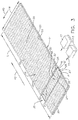
FIG. 3 is a perspective view of the first example of the composite part and cameras ofFIG. 2 with at least a portion of the first ply removed; -
FIG. 4 is a perspective partially broken view of the second example of the composite part and cameras used for measuring residual strain in a cured composite part; -
FIG. 5 is a perspective view of the second example of the composite part ofFIG. 4 with at least a portion of the first ply removed and a portion of a third ply removed; -
FIG. 6 is a perspective partially broken away view ofFIG. 4 of the second example of the composite part with the second ply having chopped fibers; -
FIG. 7 is a side elevation view ofFIG. 4 showing two spaced apart particles on the side; and -
FIG. 8 is a side elevation view ofFIG. 5 showing at least a portion of the first ply and at least a portion of the third ply removed, the original position of the spaced apart particles shown inFIG. 7 and the position of the spaced apart particles at new locations after the removal of the at least a portion of the first and third plies. - The measuring of residual strain of a cured composite part provides a designer and fabricator beneficial information regarding the composite part. Residual strain within a composite part can facilitate the occurrence of cracking and affect fatigue performance of the composite part placed into service. As mentioned above, there is a need to provide a method for measuring the residual strain retained in a cured component part in strain gradient fields of interest within a composite part without the imposition of the encumbrances and limitations of strain gages and hole-drilling. The method and system to be described herein will provide obtaining desired strain field information without the imposition of the encumbrances and limitations incurred with employing strain gages and hole-drilling with respect to a composite part.
- The method and system to be described herein will release the residual strain of a cured composite part and permit direct measuring of the residual strain in a field of interest with use of digital camera imaging. The method and the use of the system, as will be understood, provides the opportunity to obtain measurement of a full-field strain distribution, measurements with high resolution, measurements of high gradient strain field of interest and measurements of multi-axial strain measurements on the surface of the part. Moreover, the method and use of the system eliminates geometry limitations because the residual strain measurement is not limited by strain gage installation or placement. The method and system described herein operates with removal of material of the composite part relieving restraint of the residual strain and providing optical digital imaging to facilitate the measuring of the residual strain. The operation of the method and the system herein described provides versatility in accessing residual strain measurements in particular geometries and sequences enabling the measurement of residual strain in any target geometry and with respect to a strain gradient field of interest.
- In referring to
FIG. 1 ,method 10 for measuring residual strain of a cured composite part includesstep 12 of taking a first image, withdigital camera assembly 13, as seen inFIGS. 2 , including spaced apartdigital cameras side 14 of curedcomposite part 16 withside 14 positioned transverse tofirst face side 18. Curedcomposite part 16 includesfirst ply 20 which includesfirst side 22 positioned onfirst face side 18 ofcomposite part 16.Second ply 24 includesfirst side 26 positioned on and along an opposingsecond side 28 offirst ply 20.First ply 20 includesfibers 30 andsecond ply 24 includesfibers 32.First ply 20 andsecond ply 24 are positioned in overlying relationship to one another. At least a portion offibers 30 offirst ply 20 are positioned in angular relationship with at least a portion offibers 32 ofsecond ply 24. In this example,fibers 30 andfibers 32 offirst ply 20 andsecond ply 24, respectively, extend transverse to one another. At least two spaced apart particles A and B are positioned onside 14 of curedcomposite part 16 and are associated withsecond ply 24. In this example two spaced apart particles A and B are positioned onsecond ply 24. -
Method 10 further includesstep 34 of removing at least a portion 36 (shown as removed portion offirst ply 20 inFIG. 3 ) offirst ply 20. As will be discussed in more detail herein,portion 36 offirst ply 20 is abraded fromcomposite part 16. With the removal of at least aportion 36 offirst ply 20,fibers 30 from the at least aportion 36 offirst ply 20 are thereby removed.Fibers 30 ofportion 36 offirst ply 20 were positioned in angular relationship with respect tofibers 32 ofsecond ply 24 and restrainedfibers 32 in strained position attained from the curing process. The removal of the at least aportion 36 offirst ply 20 or, in some examples ofmethod 10 removal of all offirst ply 20,fibers 30 withinportion 36 are correspondingly removed removing the restraint placed onfibers 32 and allowingfibers 32 to relax and the residual strain infibers 32 to reverse. The reversal of the residual strain allowscomposite part 16 to contract from the tension which had occurred during curing. - A frame of reference for cured
composite part 16, with residual strain restrained, is shown with at least two spaced apart particles A and B positioned onsecond ply 24 onside 14 ofcomposite part 16, as seen inFIG. 2 . The positions of the at least two particles A and B are initial reference points on curedpart 16, whereinfirst ply 20 andsecond ply 24 have incurred strain as a result of the curing ofcomposite part 16. Thus, withstep 34 of removing at least aportion 36 offirst ply 20, restraint which had been imparted byfirst ply 20 to second ply 24 at that location ofportion 36 is removed. Second ply 24 at the location relaxes allowingsecond ply 24 at that location to reverse the residual strain imparted tosecond ply 24 from the curing process. As a result, as seen inFIG. 3 , the original positions of at least two particles A and B, prior to removal ofportion 36, move to new respective positions A' and B', respectively with the removal ofportion 36. -
Method 10 further includesstep 38 of taking a second image of at least two spaced apart particles A and B which have now moved to positions A' and B' respectively with the reverse of the residual strain contractingsecond ply 24 after the removal of at least aportion 36 offirst ply 20. In this example, as seen inFIG. 2 ,composite part 16 was initially positioned in a predetermined position anddigital camera assembly 13 was positioned in a second predetermined position at thetime step 12 of taking the first image took place. In this example,composite part 16 is removed from the predetermined position with the completion ofstep 12 of taking the first image. With the removal of at least aportion 36 of first plycomposite part 16,composite part 16 is re-positioned at the predetermined position withdigital camera assembly 13 having remained in the second predetermined position, as seen inFIG. 3 . Thus, withstep 38 of taking of the second image performed, the shift of positions of the at least two particles of A and B to A' and B' respectively, represents the residual strain that was retained incomposite part 16 from the curing process within this field of interest prior to the removal ofportion 36 offirst ply 20. As a result, determining the residual strain, as will be discussed herein, is directly measured and ascertained through use of digitaloptical camera assembly 13 without being encumbered by the limitations imposed by strain gages and hole-drillingcomposite part 16. -
Method 10 for measuring residual strain of a cured composite part further includes preparing curedcomposite part 16 prior to step 12 of taking the first image. Preparing curedcomposite part 16 includes, in this example, coatingside 14 ofcomposite part 16, which includes in this example coating edges offirst ply 20 and thesecond ply 24 with paint. With the paint applied, which provides a visual background forside 14, the preparing ofcomposite part 16 further includes distributing a plurality of particles onto the paint wherein the plurality of particles are in visual contrast with the paint. The distributing of the plurality of particles onto the paint includes, in this example, spraying of the particles onto the paint. The plurality of particles can include toner and/or include paint speckles. - The plurality of
particles 39 can be seen for example inFIGS. 7 and 8 for composite part 16' which will be discussed herein. The visual contrast between the paint as background and theparticles 39 provide ease in identification of at least two particles A and B. The contrast can be accomplished with using different colors and/or brightness in colors that are applied. Application of clear coat over the paint andparticles 39 provide protection to the particles when, for example, at least aportion 36 offirst ply 20 is removed. A visual contrast in this example employs white paint andblack toner particles 39. - As seen in
FIG. 3 , instep 12 of taking first image in this example includesfibers 30 offirst ply 20 extend in afirst direction 40 across width W of curedcomposite part 16 andfibers 32 ofsecond ply 24 extend in asecond direction 42 along length L of curedcomposite part 16. In this example,second direction 42 is transverse tofirst direction 40. As mentioned earlier the restraint maintained betweenfirst ply 20 andsecond ply 24 is accomplished with at least a portion offibers 30 are positioned in angular relationship with at least a portion offibers 32. -
Fibers 30 offirst ply 20 in this example are in angular relationship withfibers 32 ofsecond ply 24 and restrain the strain that has been imparted tocomposite part 16 during the curing process. This restraint can be accomplished with various different directional extending fibers betweenfirst ply 20 andsecond ply 24. This angular direction of fibers can be accomplished a number of different ways. For example, unidirectional fibers infirst ply 20 can be angularly oriented relative to unidirectional fibers insecond ply 24. Woven fibers withinfirst ply 20 and woven fibers insecond ply 24 can be angularly oriented with respect to one another. Using different fiber structures withinfirst ply 20 andsecond ply 24 can be employed, for example, a unidirectional fiber may be employed infirst ply 20 and angularly oriented with respect to a woven fiber insecond ply 24. Various combinations of fibers positioned withinfirst ply 20 andsecond ply 24 can provide the needed angular orientation between fibers of the two plies. Additional angular orientations of fibers can also be accomplished with utilizing choppedfibers 44 as seen for example insecond ply 24 inFIG. 6 . In this example, at least a portion of choppedfibers 44, which extend in a plurality of directions, are in angular relationship with respect to fibers in the plies between which second ply 24 is sandwiched, as will be discussed further herein. The restraint, in the example shown inFIGS. 2 and3 , is accomplished so long as an angular relationship of at least a portion of the fibers offirst ply 20 is established with at least a portion of the fibers withinsecond ply 24. InFIGS. 2 and3 choppedfibers 44 can be employed in one or both of first andsecond plies - In referring to
FIG. 2 , step 12 for taking the first image includes taking the first image stereographically and locating and identifying at least two spaced apart particles A and B which in this example are located onsecond ply 24. At least two spaced apart particles A and B can be seen inFIG. 2 and for example inFIG. 7 .Digital camera assembly 13 in this example, as seen inFIG. 2 , includes two spaced apartdigital cameras side 14 ofcomposite part 16. In this example wherein twoplies second ply 24 in a position such that with removal of at least aportion 36 offirst ply 20, at least two particles A and B are not damaged or removed. Also it is beneficial to select at least two spaced apart particles A and B within an alignment offirst recess 46 where at least aportion 36 offirst ply 20 has been removed as seen inFIG. 3 . In the employment ofmethod 10, numerous pairs of particles can be selected to be used for measuring residual strain within a selected field of interest. - In
step 34 for removing at least aportion 36 offirst ply 20 as seen inFIG. 3 , whereinportion 36 has been removed, includes in this example, removing a portion offirst ply 20 less than an entire length L ofside 14 of curedcomposite part 16. In addition, in thisexample step 34 of removing at least aportion 36 offirst ply 20 further includes removing the at least a portion of thefirst ply 20 along width W of curedcomposite part 16. In this example, at least aportion 36 offirst ply 20 includes the entire width W of curedcomposite part 16, as seen inFIG. 3 . It should be understood, a portion offirst ply 20 or all offirst ply 20 could be removed in carrying outMethod 10 for measuring the residual strain withincomposite part 16 herein. -
Step 34 of removing at least aportion 36 offirst ply 20 includes using an abrading tool (not shown) and abrading, in this example,portion 36 away fromfirst ply 20 ofcomposite part 16 and forming afirst recess 46 incomposite part 16, as seen inFIG. 3 . In thisexample recess 46 extends across a portion of length L and across an entire width W ofcomposite part 16. With having exercisedstep 34 of removing at least aportion 36 offirst ply 20, as seen inFIG. 3 , step 38 can be employed for taking second image of two spaced apart particles A and B positioned onside 14. In this example, particles A and B are positioned onsecond ply 24 of curedcomposite part 16. - With at least a
portion 36 offirst ply 20 removed, two spaced apart particles A and B have now moved to positions A' and B' respectively. They have moved corresponding to a reverse of the residual strain which had been originally imparted tocomposite part 16 as a result of curing. As a result, of determining the change of positions of A to A' and B to B' and understanding the difference in locations between A and B and the current difference in locations between A' and B', determining the residual strain is measured and ascertained in this field of interest for curedcomposite part 16. - In referring to
FIGS. 4-6 and7 and 8 ,method 10 for measuring residual strain in a cured composite part 16' is shown and discussed herein with respect to composite part 16' including three overlying plies of composite material. The numbering identification of elements in association with two ply construction ofcomposite part 16 shown inFIGS. 2 and3 that are similar elements with respect to the three ply construction of composite part 16' ofFIGS. 4-6 and7 and 8 will have the same numbering. In referring toFIG. 4 , step 34 of taking a first image includes composite part 16' having third ply 48 which includes afirst side 50 positioned on and along an opposingsecond side 52 ofsecond ply 24 such thatthird ply 48 is in overlying relationship withsecond ply 24 and such thatsecond ply 24 is positioned betweenfirst ply 20 andthird ply 48.Third ply 48 includesfibers 54 wherein at least a portion offibers 54 ofthird ply 48 are positioned in angular relationship with at least a portion offibers 32 ofsecond ply 24. The first image is taken withdigital camera assembly 13 with spaced apartdigital cameras - In referring to
FIG. 5 , step 34 of removing at least aportion 36 offirst ply 20 includes the at least aportion 36 offirst ply 20 removed forms, in this example,first recess 46 in cured composite part 16' aligned with at least two particles A andB. Step 34 of removing at least aportion 36 offirst ply 20 further includes removing at least aportion 56 ofthird ply 48 formingsecond recess 58 in cured composite part 16' aligned with the at least two particles A and B. In this example, the at least two particles A and B are positioned onsecond ply 24 so as not to be damaged or removed at the time of removal of the at least aportion 36 offirst ply 20 and removal of at least aportion 56 ofthird ply 48.Step 34 of removing at least aportion 36 offirst ply 20 and at least aportion 56 ofthird ply 48, as seen removed inFIG. 5 , is accomplished in this example with abrading with an abrading tool first ply 20 andthird ply 48. -
Step 34 for removing at least aportion 36 offirst ply 20 and at least aportion 56 ofthird ply 48 can be seen inFIG. 5 whereinportion Portion 36 has been removed with removing a portion offirst ply 20 less than an entire length L ofside 14 of curedcomposite part 16 andportion 56 has been removed with removing a portion ofthird ply 48 less than an entire length L ofside 14 of curedcomposite part 16. In addition, in thisexample step 34 of removing at least aportion 36 offirst ply 20 further includes removing the at least aportion 36 of thefirst ply 20 along width W of cured composite part 16' and includes removing at least aportion 56 ofthird ply 48 along width W of composite part 16'. In this example, at least aportion 36 offirst ply 20 and at least aportion 56 ofthird ply 48 include the entire width W of cured composite part 16'. It should be understood, a portion offirst ply 20 or all offirst ply 20 can be removed and a portion ofthird ply 48 or all ofthird ply 48 can be removed in carrying out measuring the residual strain. In the case of less than all offirst ply 20 and all ofthird ply 48 being removed, withportions respective recesses first ply 20 andthird ply 48, respectively, are positioned symmetrically positioned relative to cured composite part 16'. In this example, with removal of at least aportion 36 offirst ply 20 and removal of at least aportion 56 ofthird ply 48 having occurred,step 38 of the taking of the second image of the at least two spaced apart particles A and B takes place. - As mentioned earlier for positioning of
composite part 16 in a predetermined position, likewise composite part 16' is positioned in a predetermined position as seen inFIG. 4 anddigital camera assembly 13 is positioned in a second predetermined position at the time of taking the first image of at least two particles A and B. In this example, composite part 16' is removed from the predetermined position to remove at least aportion 36 and at least aportion 56 of first andthird plies FIG. 5 withdigital camera assembly 13 having remained in second predetermined position inFIG. 5 . With composite part 16' in the predetermined position, step 38 of taking the second image of the at least two spaced apart particles A and B occurs with usingdigital camera assembly 13 havingdigital camera 15 spaced apart fromdigital camera 17 taking a stereographic image. - As discussed earlier with respect to
composite part 16, composite part 16' likewise incurred strain during the curing process and the at least two spaced apart particles A and B as seen inFIG. 7 represent positions oncomposite part 16 whereincomposite part 16 has incurred strain in contracting during the curing process. With the removal ofportion 36 offirst ply 20 andportion 56 ofthird ply 48,second ply 24 atfirst recess 46 and atsecond recess 56 relaxes and the residual strain reverses moving particles A and B to new positions to now be positioned on contractedsecond ply 24 to A' and B' as seen inFIG. 8 . With positioning of composite part 16' placed back into thepredetermined position step 38, taking the second image takes place and the shifting of positions of particles A and B to particles being positioned at positions A' and B' will be a result of the removal of the residual strain in composite part 16'. - With at least a
portion 36 offirst ply 20 removed and at least aportion 56 removed fromthird ply 48 in this example, two spaced apart particles A and B have now moved to positions A' and B' respectively. They have moved, as seen inFIGS. 7 and 8 , corresponding to a reverse of the residual strain which had been originally imparted to composite part 16' as a result of curing. As a result, of determining the change of positions of A to A' and B to B' and understanding the difference in locations between A and B and the current difference in locations between A' and B', determining the residual strain is measured and ascertained in this field of interest for cured composite part 16'. - As seen in the example shown for composite part 16' in
FIG. 4 ,fibers 30 offirst ply 20 andfibers 54 ofthird ply 48 extend infirst direction 40 andfibers 32 insecond ply 24 extend in asecond direction 42. As similarly discussed above with respect tocomposite part 16, the angular relationship between at least a portion offibers 30 withinfirst ply 20 with respect tofibers 32 ofsecond ply 24, on the one hand, and an angular relationship between at least a portion offibers 54 withinthird ply 48 with respect tofibers 32 ofsecond ply 24 provide restraint of residual strain in composite part 16'. Numerous configurations of fibers as discussed earlier can be employed betweenfirst ply 20,second ply 24 and alsothird ply 48 can be provided to accomplish needed restraint of residual strain which then can later be released. Another example of this configuration is shown inFIG. 6 wherein thefibers 30 offirst ply 20 andfibers 54 ofthird ply 48 extend infirst direction 40 and fibers insecond ply 24 are choppedfibers 44 which extend in a plurality of directions. Other configurations of use of chopped fibers can be employed in one or more offirst ply 20,second ply 24 andthird ply 48. - In example shown in
FIGS. 4 and5 , restraint onfibers 32 insecond ply 24 will be released upon the removal ofportion 36 offirst ply 20 andportion 56 ofthird ply 48. The restraint is obtained as discussed above as a result of the angular relationship betweenfibers 30 infirst ply 20 andfibers 32 insecond ply 24 and the angular relationship betweenfibers 54 inthird ply 48 andfibers 32 insecond ply 24. Restraint can be accomplished insecond ply 24 as discussed above with numerous varied arrangements offibers - Further included is a system for measuring residual strain in a cured composite part, which includes
first ply 20 which includesfirst side 22 positioned onfirst face side 18 of curedcomposition part 16 andsecond ply 24 includingfirst side 26 positioned on and along an opposingsecond side 28 offirst ply 20 whereinfirst ply 20 andsecond ply 24 are positioned in overlying relationship to one another. First ply 20 includesfibers 30 andsecond ply 24 includesfibers 32 wherein at least a portion offibers 30 offirst ply 20 are in angular relationship with at least a portion offibers 32 ofsecond ply 24. At least two spaced apart particles A and B are positioned onside 14 associated withsecond ply 24. Further the system includescamera assembly 13 which includes two spaced apartdigital cameras first ply 20 for removing at least aportion 36 offirst ply 20 in alignment with the at least two spaced apart particles A and B. The system as described herein facilitates the measuring of residual strain in curedcomposite part 16. - While various embodiments have been described above, this disclosure is not intended to be limited thereto. Variations can be made to the disclosed embodiments that are still within the scope of the appended claims.
Claims (15)
- Method for measuring residual strain in a cured composite part, comprising the steps of:taking (12) a first image of at least two spaced apart particles (A, B) positioned on a side (14) of the cured composite part (16) with the side positioned transverse to a first face side (18) wherein the cured composite part (16) comprising a first ply (20) comprising fibers (30) and a second ply (24) comprising fibers (32) wherein:the first ply (20) and the second ply (24) are positioned in overlying relationship to one another;at least a portion of the fibers (30) of the first ply (20) are positioned in angular relationship with at least a portion of the fibers (32) of the second ply (24); andthe at least two spaced apart particles (A, B) positioned on the side of the cured composite part are associated with the second ply (24);removing (34) at least a portion of the first ply; andtaking (38) a second image of the at least two spaced apart particles (1, B) after the at least a portion of the first ply has been removed from the cured composite part.
- The method of claim 1 further including a step of preparing the cured composite part (16) prior to taking the first image, comprising:coating the side of the cured composite part (16) comprising edges of the first ply (20) and the second ply (24) with a paint; anddistributing a plurality of particles onto the paint.
- The method of claim 2 wherein distributing the plurality of particles onto the paint include the plurality of particles are in visual contrast with the paint.
- The method of any of claims 2-3 wherein the distributing the plurality of particles onto the paint includes spraying of the particles onto the paint.
- The method of any of claims 2-4 wherein the distributing the plurality of particles includes the plurality of particles comprising one of toner or paint speckles.
- The method of any of claims 2-5 the step of preparing the cured composite part further including applying a clear coat over the paint and particles.
- The method of any of claims 1-6 wherein the fibers (30) of the first ply (20) extend in a first direction and the fibers (32) of the second ply (24) comprising a plurality of chopped fibers which extend in a plurality of directions.
- The method of any of claims 1-7 the step (12) of taking the first image including taking the first image stereographically.
- The method of any of claims 1-8 wherein the step (34) of removing at least a portion of the first ply (20) further including removing at least a portion of the first ply (20) along a length of the side of the cured composite part (16) or a width of the cured composite part (16).
- The method of any of claims 1-9 wherein the step (34) of removing the at least a portion of the first ply (20) including abrading the first ply.
- The method of any of claims 1-10 wherein:the step (38) of taking the second image including taking the second image stereoscopically; andfurther including a step of determining the residual strain of the cured composite part.
- The method of any of claims 1-11, wherein:the step (12) of taking a first image including:the cured composite part (16) comprising a third ply (48) in overlying relationship with the second ply such that the second ply is positioned between the first ply and the third ply; andthe third ply comprising fibers wherein at least a portion of the fibers of the third ply are positioned in angular relationship with at least a portion of the fibers of the second ply;the step (34) of removing at least a portion of the first ply (20) including the at least a portion of the first ply removed is aligned with the at least two particles and the step of removing the at least a portion of the first ply further including removing at least a portion of the third ply aligned with the at least two particles; andthe step (38) of the taking of the second image of the at least two spaced apart particles occurs after the removal of the at least a portion of the first ply and after the removal of the at least a portion of the third ply optionally,
wherein the fibers of the first ply (20) and the third ply extend in a first direction and the fibers of the second ply are chopped fibers which extend in a plurality of directions. - The method of claims 12 wherein:the step (34) of removing at least a portion of the first ply (20) forms a first recess in the cured composite part;the step (34) of removing at least a portion of the first ply (20) further including removing at least a portion of the third ply (48) forming a second recess in the cured composite part;the step (34) of removing at least a portion of the first ply and at least a portion of the third ply comprising abrading the first ply and abrading the third ply; andthe first and second recesses each extend across a width of the cured composite part and extend along a portion of a length of the side of the composite part.
- The method of claim 13 wherein the step (34) of removing includes the first recess and the second recess are symmetrically positioned with respect to the cured composite part.
- The method of any of claims 13-14 wherein:the step (12) of taking the first image including taking the first image stereographically;the step (38) of taking the second image including taking the second image stereographically; andfurther including determining a residual strain in the cured composite part.
Applications Claiming Priority (1)
| Application Number | Priority Date | Filing Date | Title |
|---|---|---|---|
| US15/496,264 US10066929B1 (en) | 2017-04-25 | 2017-04-25 | Method for measuring residual strain for cured composite part |
Publications (2)
| Publication Number | Publication Date |
|---|---|
| EP3395571A1 EP3395571A1 (en) | 2018-10-31 |
| EP3395571B1 true EP3395571B1 (en) | 2021-04-21 |
Family
ID=61017775
Family Applications (1)
| Application Number | Title | Priority Date | Filing Date |
|---|---|---|---|
| EP18152008.1A Active EP3395571B1 (en) | 2017-04-25 | 2018-01-17 | Method for measuring residual strain for cured composite part |
Country Status (5)
| Country | Link |
|---|---|
| US (1) | US10066929B1 (en) |
| EP (1) | EP3395571B1 (en) |
| JP (1) | JP7150435B2 (en) |
| KR (1) | KR102623477B1 (en) |
| CN (1) | CN108731607B (en) |
Families Citing this family (2)
| Publication number | Priority date | Publication date | Assignee | Title |
|---|---|---|---|---|
| JP7390144B2 (en) * | 2019-09-24 | 2023-12-01 | 三菱重工業株式会社 | Composite joint members and joint structures |
| CN111307056B (en) * | 2020-03-11 | 2021-04-20 | 武汉理工大学 | A method for measuring residual strain of composite winding pipe based on grating sensor |
Family Cites Families (25)
| Publication number | Priority date | Publication date | Assignee | Title |
|---|---|---|---|---|
| JPH04172192A (en) * | 1990-11-07 | 1992-06-19 | Nec Corp | Laser beam machine |
| JPH05346377A (en) * | 1992-06-15 | 1993-12-27 | Nippon Steel Corp | Evaluation method of residual stress of actual structure and its equipment |
| JPH07219266A (en) * | 1993-12-06 | 1995-08-18 | Xerox Corp | Image formation method |
| US5770155A (en) | 1995-11-21 | 1998-06-23 | United Technologies Corporation | Composite structure resin cure monitoring apparatus using an optical fiber grating sensor |
| JPH09280831A (en) * | 1996-04-12 | 1997-10-31 | Denki Kagaku Kogyo Kk | Method and apparatus for measuring residual internal stress / strain in the mouth and neck |
| US6493420B2 (en) * | 2000-07-21 | 2002-12-10 | The Penn State Research Foundation | Apparatus and method for in-situ measurement of residual surface stresses |
| JP2005010003A (en) | 2003-06-18 | 2005-01-13 | National Institute For Materials Science | Method for measuring residual strain and residual stress in composite materials |
| US7720259B2 (en) | 2005-08-26 | 2010-05-18 | Sony Corporation | Motion capture using primary and secondary markers |
| JP2007106553A (en) * | 2005-10-13 | 2007-04-26 | Hitachi Plant Technologies Ltd | Waste pit remaining amount detection system |
| WO2008146532A1 (en) | 2007-05-29 | 2008-12-04 | Keisoku Research Consultant Co. | Method for measuring stress in structure, and method and system for measuring distortion of object to be measured |
| JP5429864B2 (en) | 2009-07-24 | 2014-02-26 | 独立行政法人物質・材料研究機構 | Strain measurement pattern |
| US8843416B2 (en) * | 2009-09-11 | 2014-09-23 | NetESCO LLC | Determining energy consumption in a structure |
| KR101206851B1 (en) * | 2010-05-11 | 2012-11-30 | 서강대학교산학협력단 | Method for estimating residual stress of material |
| CN101839699B (en) * | 2010-05-14 | 2011-11-30 | 清华大学 | Method for measuring residual deformation of micro-nano metallic interconnect |
| JP5474729B2 (en) | 2010-10-20 | 2014-04-16 | 株式会社ブリヂストン | Laminated support and method for measuring deformation of laminated support |
| US8264675B1 (en) * | 2011-05-12 | 2012-09-11 | Georgia Tech Research Corporation | Polariscope stress measurement tool and method of use |
| US8836934B1 (en) * | 2012-05-15 | 2014-09-16 | The Boeing Company | Contamination identification system |
| CN103488850B (en) * | 2013-10-15 | 2016-04-13 | 北京航空航天大学 | A kind of heat shake compound unrelieved stress location homogenizing method |
| US9976968B2 (en) | 2013-10-18 | 2018-05-22 | Saga University | Cracking detection system and cracking detection method |
| US20160320176A1 (en) | 2013-12-20 | 2016-11-03 | Oakland University | Digital shearography ndt system for speckless objects |
| US9897440B2 (en) * | 2014-01-17 | 2018-02-20 | The Boeing Company | Method and system for determining and verifying ply orientation of a composite laminate |
| JP6520058B2 (en) | 2014-11-12 | 2019-05-29 | 横浜ゴム株式会社 | Pneumatic tire and vehicle |
| JP6345618B2 (en) * | 2015-03-05 | 2018-06-20 | 株式会社神戸製鋼所 | Residual stress estimation method and residual stress estimation apparatus |
| CN105044104A (en) * | 2015-06-01 | 2015-11-11 | 上海交通大学 | Stress test system based on digital image correlation method and application thereof |
| JP2017032530A (en) | 2015-08-06 | 2017-02-09 | トヨタ自動車株式会社 | Measuring method of displacement of rough material |
-
2017
- 2017-04-25 US US15/496,264 patent/US10066929B1/en active Active
-
2018
- 2018-01-04 JP JP2018000086A patent/JP7150435B2/en active Active
- 2018-01-17 EP EP18152008.1A patent/EP3395571B1/en active Active
- 2018-01-17 CN CN201810044479.7A patent/CN108731607B/en active Active
- 2018-03-30 KR KR1020180037301A patent/KR102623477B1/en active Active
Non-Patent Citations (1)
| Title |
|---|
| None * |
Also Published As
| Publication number | Publication date |
|---|---|
| CN108731607B (en) | 2021-06-15 |
| US10066929B1 (en) | 2018-09-04 |
| KR102623477B1 (en) | 2024-01-09 |
| CN108731607A (en) | 2018-11-02 |
| KR20180119480A (en) | 2018-11-02 |
| JP7150435B2 (en) | 2022-10-11 |
| JP2018185285A (en) | 2018-11-22 |
| EP3395571A1 (en) | 2018-10-31 |
Similar Documents
| Publication | Publication Date | Title |
|---|---|---|
| JP5206175B2 (en) | Deformation measuring device | |
| Heim et al. | Analysis of tow architecture variability in biaxially braided composite tubes | |
| CN105365227A (en) | Systems and methods for fiber placement inspection during fabrication of fiber-reinforced composite components | |
| Khiêm et al. | An averaging based hyperelastic modeling and experimental analysis of non-crimp fabrics | |
| EP3587997A1 (en) | Residual thermal strain measurement method, residual thermal strain measurement device, and program therefor | |
| DE102017203426A1 (en) | Calibration tray, measuring device and method for calibrating driver assistance systems | |
| US10066929B1 (en) | Method for measuring residual strain for cured composite part | |
| Berring et al. | Torsional performance of wind turbine blades—Part I: Experimental investigation | |
| KR101833245B1 (en) | METHOD AND SYSTEM FOR CALIBRATION OF SURFACE MEASUREMENT DEVICE USING Phase measuring deflectometry | |
| JP6743535B2 (en) | Tire stiffness test method | |
| KR100550108B1 (en) | Two-dimensional hole displacement measuring device and system of tunnel using fiber optic sensor | |
| JP2005010003A (en) | Method for measuring residual strain and residual stress in composite materials | |
| ITSV980015A1 (en) | METHOD FOR THE CORRECTION AND / OR CALIBRATION OF MAGNETIC FIELDS IN PARTICULAR IN MAGNETS FOR MACHINES FOR DETECTION OF IMAGES IN REFERENCE | |
| DE112019007965T5 (en) | ROTATING ELECTRICAL MACHINE TESTING DEVICE, ROTATING ELECTRICAL MACHINE, AND ROTATING ELECTRICAL MACHINE TESTING METHOD | |
| Ban et al. | Pre-stress-assisted nanoimprint lithography for fabricating high-density diffraction gratings | |
| JP2009506920A (en) | Method for measuring anomalous part of surface shape of aircraft structural panel and system for executing the method | |
| JP7555300B2 (en) | Measuring device and radial key manufacturing method | |
| KR100604944B1 (en) | Distortion measurement method of semiconductor exposure apparatus | |
| Cao et al. | A novel approach for measuring the discontinuous deformation fields based on the digital image correlation method | |
| KR20090130603A (en) | Evaluation method of wide-angle lens module and evaluation chart used therein | |
| JP2001336993A (en) | Neutron residual stress measurement method | |
| Marotta et al. | Some problems arising during the experimental characterization of compliant knitted mesh | |
| JP7327072B2 (en) | Method for estimating internal structure of tire during running | |
| Keaton | Investigating the effect of bead geometry on fiber orientation and thermomechanical properties for large-format extrusion-based additive manufacturing | |
| Chiang et al. | Multipurpose optical moiré processor |
Legal Events
| Date | Code | Title | Description |
|---|---|---|---|
| PUAI | Public reference made under article 153(3) epc to a published international application that has entered the european phase |
Free format text: ORIGINAL CODE: 0009012 |
|
| STAA | Information on the status of an ep patent application or granted ep patent |
Free format text: STATUS: REQUEST FOR EXAMINATION WAS MADE |
|
| 17P | Request for examination filed |
Effective date: 20180117 |
|
| AK | Designated contracting states |
Kind code of ref document: A1 Designated state(s): AL AT BE BG CH CY CZ DE DK EE ES FI FR GB GR HR HU IE IS IT LI LT LU LV MC MK MT NL NO PL PT RO RS SE SI SK SM TR |
|
| AX | Request for extension of the european patent |
Extension state: BA ME |
|
| GRAP | Despatch of communication of intention to grant a patent |
Free format text: ORIGINAL CODE: EPIDOSNIGR1 |
|
| STAA | Information on the status of an ep patent application or granted ep patent |
Free format text: STATUS: GRANT OF PATENT IS INTENDED |
|
| INTG | Intention to grant announced |
Effective date: 20201104 |
|
| GRAS | Grant fee paid |
Free format text: ORIGINAL CODE: EPIDOSNIGR3 |
|
| GRAA | (expected) grant |
Free format text: ORIGINAL CODE: 0009210 |
|
| STAA | Information on the status of an ep patent application or granted ep patent |
Free format text: STATUS: THE PATENT HAS BEEN GRANTED |
|
| AK | Designated contracting states |
Kind code of ref document: B1 Designated state(s): AL AT BE BG CH CY CZ DE DK EE ES FI FR GB GR HR HU IE IS IT LI LT LU LV MC MK MT NL NO PL PT RO RS SE SI SK SM TR |
|
| REG | Reference to a national code |
Ref country code: GB Ref legal event code: FG4D |
|
| REG | Reference to a national code |
Ref country code: CH Ref legal event code: EP |
|
| REG | Reference to a national code |
Ref country code: DE Ref legal event code: R096 Ref document number: 602018015680 Country of ref document: DE Ref country code: IE Ref legal event code: FG4D |
|
| REG | Reference to a national code |
Ref country code: AT Ref legal event code: REF Ref document number: 1384214 Country of ref document: AT Kind code of ref document: T Effective date: 20210515 |
|
| REG | Reference to a national code |
Ref country code: LT Ref legal event code: MG9D |
|
| REG | Reference to a national code |
Ref country code: AT Ref legal event code: MK05 Ref document number: 1384214 Country of ref document: AT Kind code of ref document: T Effective date: 20210421 |
|
| REG | Reference to a national code |
Ref country code: NL Ref legal event code: MP Effective date: 20210421 |
|
| PG25 | Lapsed in a contracting state [announced via postgrant information from national office to epo] |
Ref country code: FI Free format text: LAPSE BECAUSE OF FAILURE TO SUBMIT A TRANSLATION OF THE DESCRIPTION OR TO PAY THE FEE WITHIN THE PRESCRIBED TIME-LIMIT Effective date: 20210421 Ref country code: LT Free format text: LAPSE BECAUSE OF FAILURE TO SUBMIT A TRANSLATION OF THE DESCRIPTION OR TO PAY THE FEE WITHIN THE PRESCRIBED TIME-LIMIT Effective date: 20210421 Ref country code: NL Free format text: LAPSE BECAUSE OF FAILURE TO SUBMIT A TRANSLATION OF THE DESCRIPTION OR TO PAY THE FEE WITHIN THE PRESCRIBED TIME-LIMIT Effective date: 20210421 Ref country code: HR Free format text: LAPSE BECAUSE OF FAILURE TO SUBMIT A TRANSLATION OF THE DESCRIPTION OR TO PAY THE FEE WITHIN THE PRESCRIBED TIME-LIMIT Effective date: 20210421 Ref country code: BG Free format text: LAPSE BECAUSE OF FAILURE TO SUBMIT A TRANSLATION OF THE DESCRIPTION OR TO PAY THE FEE WITHIN THE PRESCRIBED TIME-LIMIT Effective date: 20210721 Ref country code: AT Free format text: LAPSE BECAUSE OF FAILURE TO SUBMIT A TRANSLATION OF THE DESCRIPTION OR TO PAY THE FEE WITHIN THE PRESCRIBED TIME-LIMIT Effective date: 20210421 |
|
| PG25 | Lapsed in a contracting state [announced via postgrant information from national office to epo] |
Ref country code: GR Free format text: LAPSE BECAUSE OF FAILURE TO SUBMIT A TRANSLATION OF THE DESCRIPTION OR TO PAY THE FEE WITHIN THE PRESCRIBED TIME-LIMIT Effective date: 20210722 Ref country code: IS Free format text: LAPSE BECAUSE OF FAILURE TO SUBMIT A TRANSLATION OF THE DESCRIPTION OR TO PAY THE FEE WITHIN THE PRESCRIBED TIME-LIMIT Effective date: 20210821 Ref country code: PT Free format text: LAPSE BECAUSE OF FAILURE TO SUBMIT A TRANSLATION OF THE DESCRIPTION OR TO PAY THE FEE WITHIN THE PRESCRIBED TIME-LIMIT Effective date: 20210823 Ref country code: NO Free format text: LAPSE BECAUSE OF FAILURE TO SUBMIT A TRANSLATION OF THE DESCRIPTION OR TO PAY THE FEE WITHIN THE PRESCRIBED TIME-LIMIT Effective date: 20210721 Ref country code: PL Free format text: LAPSE BECAUSE OF FAILURE TO SUBMIT A TRANSLATION OF THE DESCRIPTION OR TO PAY THE FEE WITHIN THE PRESCRIBED TIME-LIMIT Effective date: 20210421 Ref country code: LV Free format text: LAPSE BECAUSE OF FAILURE TO SUBMIT A TRANSLATION OF THE DESCRIPTION OR TO PAY THE FEE WITHIN THE PRESCRIBED TIME-LIMIT Effective date: 20210421 Ref country code: SE Free format text: LAPSE BECAUSE OF FAILURE TO SUBMIT A TRANSLATION OF THE DESCRIPTION OR TO PAY THE FEE WITHIN THE PRESCRIBED TIME-LIMIT Effective date: 20210421 Ref country code: RS Free format text: LAPSE BECAUSE OF FAILURE TO SUBMIT A TRANSLATION OF THE DESCRIPTION OR TO PAY THE FEE WITHIN THE PRESCRIBED TIME-LIMIT Effective date: 20210421 |
|
| REG | Reference to a national code |
Ref country code: DE Ref legal event code: R097 Ref document number: 602018015680 Country of ref document: DE |
|
| PG25 | Lapsed in a contracting state [announced via postgrant information from national office to epo] |
Ref country code: RO Free format text: LAPSE BECAUSE OF FAILURE TO SUBMIT A TRANSLATION OF THE DESCRIPTION OR TO PAY THE FEE WITHIN THE PRESCRIBED TIME-LIMIT Effective date: 20210421 Ref country code: DK Free format text: LAPSE BECAUSE OF FAILURE TO SUBMIT A TRANSLATION OF THE DESCRIPTION OR TO PAY THE FEE WITHIN THE PRESCRIBED TIME-LIMIT Effective date: 20210421 Ref country code: CZ Free format text: LAPSE BECAUSE OF FAILURE TO SUBMIT A TRANSLATION OF THE DESCRIPTION OR TO PAY THE FEE WITHIN THE PRESCRIBED TIME-LIMIT Effective date: 20210421 Ref country code: SM Free format text: LAPSE BECAUSE OF FAILURE TO SUBMIT A TRANSLATION OF THE DESCRIPTION OR TO PAY THE FEE WITHIN THE PRESCRIBED TIME-LIMIT Effective date: 20210421 Ref country code: SK Free format text: LAPSE BECAUSE OF FAILURE TO SUBMIT A TRANSLATION OF THE DESCRIPTION OR TO PAY THE FEE WITHIN THE PRESCRIBED TIME-LIMIT Effective date: 20210421 Ref country code: ES Free format text: LAPSE BECAUSE OF FAILURE TO SUBMIT A TRANSLATION OF THE DESCRIPTION OR TO PAY THE FEE WITHIN THE PRESCRIBED TIME-LIMIT Effective date: 20210421 Ref country code: EE Free format text: LAPSE BECAUSE OF FAILURE TO SUBMIT A TRANSLATION OF THE DESCRIPTION OR TO PAY THE FEE WITHIN THE PRESCRIBED TIME-LIMIT Effective date: 20210421 |
|
| PLBE | No opposition filed within time limit |
Free format text: ORIGINAL CODE: 0009261 |
|
| STAA | Information on the status of an ep patent application or granted ep patent |
Free format text: STATUS: NO OPPOSITION FILED WITHIN TIME LIMIT |
|
| 26N | No opposition filed |
Effective date: 20220124 |
|
| PG25 | Lapsed in a contracting state [announced via postgrant information from national office to epo] |
Ref country code: IS Free format text: LAPSE BECAUSE OF FAILURE TO SUBMIT A TRANSLATION OF THE DESCRIPTION OR TO PAY THE FEE WITHIN THE PRESCRIBED TIME-LIMIT Effective date: 20210821 Ref country code: AL Free format text: LAPSE BECAUSE OF FAILURE TO SUBMIT A TRANSLATION OF THE DESCRIPTION OR TO PAY THE FEE WITHIN THE PRESCRIBED TIME-LIMIT Effective date: 20210421 |
|
| PG25 | Lapsed in a contracting state [announced via postgrant information from national office to epo] |
Ref country code: IT Free format text: LAPSE BECAUSE OF FAILURE TO SUBMIT A TRANSLATION OF THE DESCRIPTION OR TO PAY THE FEE WITHIN THE PRESCRIBED TIME-LIMIT Effective date: 20210421 |
|
| PG25 | Lapsed in a contracting state [announced via postgrant information from national office to epo] |
Ref country code: MC Free format text: LAPSE BECAUSE OF FAILURE TO SUBMIT A TRANSLATION OF THE DESCRIPTION OR TO PAY THE FEE WITHIN THE PRESCRIBED TIME-LIMIT Effective date: 20210421 |
|
| REG | Reference to a national code |
Ref country code: CH Ref legal event code: PL |
|
| REG | Reference to a national code |
Ref country code: BE Ref legal event code: MM Effective date: 20220131 |
|
| PG25 | Lapsed in a contracting state [announced via postgrant information from national office to epo] |
Ref country code: LU Free format text: LAPSE BECAUSE OF NON-PAYMENT OF DUE FEES Effective date: 20220117 |
|
| PG25 | Lapsed in a contracting state [announced via postgrant information from national office to epo] |
Ref country code: BE Free format text: LAPSE BECAUSE OF NON-PAYMENT OF DUE FEES Effective date: 20220131 |
|
| PG25 | Lapsed in a contracting state [announced via postgrant information from national office to epo] |
Ref country code: LI Free format text: LAPSE BECAUSE OF NON-PAYMENT OF DUE FEES Effective date: 20220131 Ref country code: CH Free format text: LAPSE BECAUSE OF NON-PAYMENT OF DUE FEES Effective date: 20220131 |
|
| PG25 | Lapsed in a contracting state [announced via postgrant information from national office to epo] |
Ref country code: IE Free format text: LAPSE BECAUSE OF NON-PAYMENT OF DUE FEES Effective date: 20220117 |
|
| P01 | Opt-out of the competence of the unified patent court (upc) registered |
Effective date: 20230516 |
|
| PG25 | Lapsed in a contracting state [announced via postgrant information from national office to epo] |
Ref country code: HU Free format text: LAPSE BECAUSE OF FAILURE TO SUBMIT A TRANSLATION OF THE DESCRIPTION OR TO PAY THE FEE WITHIN THE PRESCRIBED TIME-LIMIT; INVALID AB INITIO Effective date: 20180117 |
|
| PG25 | Lapsed in a contracting state [announced via postgrant information from national office to epo] |
Ref country code: MK Free format text: LAPSE BECAUSE OF FAILURE TO SUBMIT A TRANSLATION OF THE DESCRIPTION OR TO PAY THE FEE WITHIN THE PRESCRIBED TIME-LIMIT Effective date: 20210421 Ref country code: CY Free format text: LAPSE BECAUSE OF FAILURE TO SUBMIT A TRANSLATION OF THE DESCRIPTION OR TO PAY THE FEE WITHIN THE PRESCRIBED TIME-LIMIT Effective date: 20210421 |
|
| PG25 | Lapsed in a contracting state [announced via postgrant information from national office to epo] |
Ref country code: MT Free format text: LAPSE BECAUSE OF FAILURE TO SUBMIT A TRANSLATION OF THE DESCRIPTION OR TO PAY THE FEE WITHIN THE PRESCRIBED TIME-LIMIT Effective date: 20210421 |
|
| PG25 | Lapsed in a contracting state [announced via postgrant information from national office to epo] |
Ref country code: TR Free format text: LAPSE BECAUSE OF FAILURE TO SUBMIT A TRANSLATION OF THE DESCRIPTION OR TO PAY THE FEE WITHIN THE PRESCRIBED TIME-LIMIT Effective date: 20210421 |
|
| PGFP | Annual fee paid to national office [announced via postgrant information from national office to epo] |
Ref country code: GB Payment date: 20260127 Year of fee payment: 9 |
|
| PGFP | Annual fee paid to national office [announced via postgrant information from national office to epo] |
Ref country code: DE Payment date: 20260128 Year of fee payment: 9 |
|
| PGFP | Annual fee paid to national office [announced via postgrant information from national office to epo] |
Ref country code: FR Payment date: 20260126 Year of fee payment: 9 |