EP3395523A1 - A cutting tool - Google Patents
A cutting tool Download PDFInfo
- Publication number
- EP3395523A1 EP3395523A1 EP18168571.0A EP18168571A EP3395523A1 EP 3395523 A1 EP3395523 A1 EP 3395523A1 EP 18168571 A EP18168571 A EP 18168571A EP 3395523 A1 EP3395523 A1 EP 3395523A1
- Authority
- EP
- European Patent Office
- Prior art keywords
- cutting
- abrasive
- flank surface
- edge
- tool
- Prior art date
- Legal status (The legal status is an assumption and is not a legal conclusion. Google has not performed a legal analysis and makes no representation as to the accuracy of the status listed.)
- Granted
Links
Images


Classifications
-
- B—PERFORMING OPERATIONS; TRANSPORTING
- B23—MACHINE TOOLS; METAL-WORKING NOT OTHERWISE PROVIDED FOR
- B23B—TURNING; BORING
- B23B51/00—Tools for drilling machines
- B23B51/08—Drills combined with tool parts or tools for performing additional working
-
- B—PERFORMING OPERATIONS; TRANSPORTING
- B23—MACHINE TOOLS; METAL-WORKING NOT OTHERWISE PROVIDED FOR
- B23B—TURNING; BORING
- B23B51/00—Tools for drilling machines
- B23B51/02—Twist drills
-
- B—PERFORMING OPERATIONS; TRANSPORTING
- B23—MACHINE TOOLS; METAL-WORKING NOT OTHERWISE PROVIDED FOR
- B23B—TURNING; BORING
- B23B51/00—Tools for drilling machines
- B23B51/04—Drills for trepanning
-
- B—PERFORMING OPERATIONS; TRANSPORTING
- B23—MACHINE TOOLS; METAL-WORKING NOT OTHERWISE PROVIDED FOR
- B23P—METAL-WORKING NOT OTHERWISE PROVIDED FOR; COMBINED OPERATIONS; UNIVERSAL MACHINE TOOLS
- B23P15/00—Making specific metal objects by operations not covered by a single other subclass or a group in this subclass
- B23P15/28—Making specific metal objects by operations not covered by a single other subclass or a group in this subclass cutting tools
-
- B—PERFORMING OPERATIONS; TRANSPORTING
- B28—WORKING CEMENT, CLAY, OR STONE
- B28D—WORKING STONE OR STONE-LIKE MATERIALS
- B28D1/00—Working stone or stone-like materials, e.g. brick, concrete or glass, not provided for elsewhere; Machines, devices, tools therefor
- B28D1/14—Working stone or stone-like materials, e.g. brick, concrete or glass, not provided for elsewhere; Machines, devices, tools therefor by boring or drilling
- B28D1/146—Tools therefor
-
- B—PERFORMING OPERATIONS; TRANSPORTING
- B23—MACHINE TOOLS; METAL-WORKING NOT OTHERWISE PROVIDED FOR
- B23B—TURNING; BORING
- B23B2200/00—Details of cutting inserts
- B23B2200/12—Side or flank surfaces
- B23B2200/123—Side or flank surfaces curved
-
- B—PERFORMING OPERATIONS; TRANSPORTING
- B23—MACHINE TOOLS; METAL-WORKING NOT OTHERWISE PROVIDED FOR
- B23B—TURNING; BORING
- B23B2200/00—Details of cutting inserts
- B23B2200/20—Top or side views of the cutting edge
- B23B2200/204—Top or side views of the cutting edge with discontinuous cutting edge
-
- B—PERFORMING OPERATIONS; TRANSPORTING
- B23—MACHINE TOOLS; METAL-WORKING NOT OTHERWISE PROVIDED FOR
- B23B—TURNING; BORING
- B23B2200/00—Details of cutting inserts
- B23B2200/24—Cross section of the cutting edge
- B23B2200/245—Cross section of the cutting edge rounded
-
- B—PERFORMING OPERATIONS; TRANSPORTING
- B23—MACHINE TOOLS; METAL-WORKING NOT OTHERWISE PROVIDED FOR
- B23B—TURNING; BORING
- B23B2200/00—Details of cutting inserts
- B23B2200/28—Angles
-
- B—PERFORMING OPERATIONS; TRANSPORTING
- B23—MACHINE TOOLS; METAL-WORKING NOT OTHERWISE PROVIDED FOR
- B23B—TURNING; BORING
- B23B2226/00—Materials of tools or workpieces not comprising a metal
- B23B2226/12—Boron nitride
- B23B2226/125—Boron nitride cubic [CBN]
-
- B—PERFORMING OPERATIONS; TRANSPORTING
- B23—MACHINE TOOLS; METAL-WORKING NOT OTHERWISE PROVIDED FOR
- B23B—TURNING; BORING
- B23B2226/00—Materials of tools or workpieces not comprising a metal
- B23B2226/31—Diamond
-
- B—PERFORMING OPERATIONS; TRANSPORTING
- B23—MACHINE TOOLS; METAL-WORKING NOT OTHERWISE PROVIDED FOR
- B23B—TURNING; BORING
- B23B2228/00—Properties of materials of tools or workpieces, materials of tools or workpieces applied in a specific manner
- B23B2228/12—Abrasive
-
- B—PERFORMING OPERATIONS; TRANSPORTING
- B23—MACHINE TOOLS; METAL-WORKING NOT OTHERWISE PROVIDED FOR
- B23B—TURNING; BORING
- B23B2251/00—Details of tools for drilling machines
- B23B2251/28—Arrangement of teeth
- B23B2251/285—Cutting teeth arranged at different heights
-
- B—PERFORMING OPERATIONS; TRANSPORTING
- B23—MACHINE TOOLS; METAL-WORKING NOT OTHERWISE PROVIDED FOR
- B23P—METAL-WORKING NOT OTHERWISE PROVIDED FOR; COMBINED OPERATIONS; UNIVERSAL MACHINE TOOLS
- B23P15/00—Making specific metal objects by operations not covered by a single other subclass or a group in this subclass
- B23P15/28—Making specific metal objects by operations not covered by a single other subclass or a group in this subclass cutting tools
- B23P15/32—Making specific metal objects by operations not covered by a single other subclass or a group in this subclass cutting tools twist-drills
-
- Y—GENERAL TAGGING OF NEW TECHNOLOGICAL DEVELOPMENTS; GENERAL TAGGING OF CROSS-SECTIONAL TECHNOLOGIES SPANNING OVER SEVERAL SECTIONS OF THE IPC; TECHNICAL SUBJECTS COVERED BY FORMER USPC CROSS-REFERENCE ART COLLECTIONS [XRACs] AND DIGESTS
- Y10—TECHNICAL SUBJECTS COVERED BY FORMER USPC
- Y10T—TECHNICAL SUBJECTS COVERED BY FORMER US CLASSIFICATION
- Y10T408/00—Cutting by use of rotating axially moving tool
- Y10T408/34—Combined cutting means
- Y10T408/352—Combined cutting means including rotating cutter other than rotating, axially moving Tool
- Y10T408/353—Crystalline cutter
-
- Y—GENERAL TAGGING OF NEW TECHNOLOGICAL DEVELOPMENTS; GENERAL TAGGING OF CROSS-SECTIONAL TECHNOLOGIES SPANNING OVER SEVERAL SECTIONS OF THE IPC; TECHNICAL SUBJECTS COVERED BY FORMER USPC CROSS-REFERENCE ART COLLECTIONS [XRACs] AND DIGESTS
- Y10—TECHNICAL SUBJECTS COVERED BY FORMER USPC
- Y10T—TECHNICAL SUBJECTS COVERED BY FORMER US CLASSIFICATION
- Y10T408/00—Cutting by use of rotating axially moving tool
- Y10T408/81—Tool having crystalline cutting edge
Definitions
- the present disclosure relates to a cutting tool having abrasive features and particularly, but not exclusively, to a drill having abrasive features.
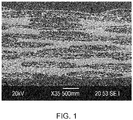
- Ceramic Matric Composite (CMC) materials are formed from ceramic fibres 10 reinforcing a ceramic matrix an example being shown in Figure 1 .
- CMC materials have excellent high temperature mechanical properties.
- CMC materials are currently being considered to replace high temperature metal alloys (such as nickel based superalloys) in applications such as gas turbine engine segments, vanes and blades, and also in combustor heat shields.
- CMC materials need machining processes such as grinding, drilling or milling to achieve the final shape of the workpiece.
- Conventional drilling cutter geometries were designed several decades ago and have been optimised for the machining of homogenous materials. For example, in the majority of drill bits, the cutting lips are the only cutting regions.
- the heterogenic, anisotropic and high hardness properties of these CMC materials means that conventional cutting tools have low material removal rates, a short working life and poor machined surface quality.
- a cutting tool comprising:
- the cutting tool geometry having abrasive particles on the flank face provides two additional abrasive zones (cutting zones) in addition to the main defined cutting edges. Increasing the quantity of effective cutting zones reduces cutting forces per cutting edge or region, and extends the cutting edge life over conventional cutting tools in which the cutting lips are the only cutting edges
- the increased quantity of cutting zones will also improve the quality of the machined surface by preventing delamination, cracking, fibre pull-out and edge chipping.
- the increased quantity of cutting zones will also improve surface finish and reduce surface roughness.
- the surface quality improvement provided by the additional cutting zones is particularly enhanced when machining small tight tolerance features, such as micro-holes and grooves in CMC and other composite materials.
- Providing a plurality of abrasive features across the flank surface improves the effectiveness of the material removal by the abrasive portion by allowing the powdery chip characteristic of CMCs to flow between the individual abrasive features.
- the abrasive features have a circular profile.
- the circular profile of the individual abrasive feature provides a balance between wear resistance and areal coverage across the flank surface.
- the abrasive features may have an alternative profile such as, for example, elliptical, square, rectangular, or lachrymiform.
- the abrasive features extend from the flank surface as conical frusta.
- each of the abrasive features as a conical frustum improves the rigidity and strength of the abrasive features over other geometries.
- the abrasive features may have an alternative geometry such as, for example, pyramidal.
- the abrasive features are arranged in two adjacent rows across the flank surface, each row extending radially across the flank surface, the first row positioned adjacent to a circumferentially trailing edge of the flank surface, the second row being radially offset from the first row.
- Providing the abrasive features in two rows extending across the radial extent of the flank surface with a second row being offset from the first row ensures the full radial extent of the flank surface can be covered by abrasive features while still maintaining 'inter feature' spaces for the removal of machining debris.
- the abrasive features may be arranged in more than two rows extending across at least a part of the flank surface.
- each abrasive feature extends from the flank surface by a feature height, the feature height increasing with radially distal feature position.
- flank surface geometry is required to be pre-machined accordingly in order to allow the position of the abrasive feature cutting edges to be aligned precisely relative to the two (or more) main cutting edges of the tool.
- each cutting edge extends linearly from the centre region of the first end to a perimetral edge of the first end, each cutting edge subtending a first angle with the longitudinal axis.
- each cutting edge is formed as a linear feature. This configuration may be advantageous when machining high hardness materials such as ceramics and the ceramic phases of, for example, CMC materials.
- each of the cutting edges may be formed with a lengthwise profile that is non-linear such as, for example, logarithmic or exponential.
- the cutting tool further comprises two or more flutes extending along at least a part of the tool body, wherein each of the two or more cutting edges corresponds to a respective one of the two or more flutes.
- each flute as a twisted flute provides an improved tool rigidity and improved chip breakage and evacuation when machining high hardness materials.
- each cutting edge may extend from the perimetral edge of the first end towards the second end along at least a part of the tool body as a straight flute.
- a cutting tool having straight flutes can be manufactured at lower cost than a cutting tool having twisted flutes.
- the cutting tool is integrally formed from a material selected from the group consisting of diamond materials and cubic boron nitride materials.
- Forming the cutting tool from a diamond material ensures that the cutting tool is sufficiently hard to effectively cut the high hardness matrix portion of, for example, CMC materials without the cutting tool suffering from a high wear rate.
- the cutting tool may be formed as a modular assembly in which separate cutting portions are attached to a common tool body.
- the cutting tool is formed from a base material selected from the group consisting of steel, and carbide materials, and the base material is provided with a coating layer selected from the group consisting of diamond materials and cubic boron nitride materials.
- Forming the cutting tool from a conventional cutting tool material and then providing a diamond coating layer makes the cutting tool cheaper to manufacture.
- a coated tool can only be reworked (re-sharpened) a limited number of times before the coating layer is exhausted.
- the feature height of each abrasive feature is equal to the corresponding depth of the cut along the respective cutting edge.
- each set of abrasive features is positioned on a flank surface adjacent to and circumferentially spaced from a respective cutting edge.
- each set of abrasive features acts as a cutting zone.
- the feature height of each abrasive feature corresponds to a depth of cut for the respective abrasive feature.
- the feature height of each abrasive feature is equal to the depth of cut of the respective adjacent cutting edge. This ensures that the process of the removal of material by the cutting tool is shared between the cutting edge and the corresponding abrasive features.
- a cutting tool comprising the steps of:
- the cutting tool geometry having abrasive particles on the flank face provides two additional abrasive zones (cutting zones) in addition to the main defined cutting edges. Increasing the quantity of effective cutting zones reduces cutting forces per cutting edge or region, and extends the cutting edge life over conventional cutting tools in which the cutting lips are the only cutting edges.
- the increased quantity of cutting zones will also improve the quality of the machined surface by preventing delamination, cracking, fibre pull-out and edge burring.
- the increased quantity of cutting zones will also improve surface finish and reduce surface roughness.
- the increased quantity of cutting zones will also improve the quality of the machined surface by preventing delamination, cracking, fibre pull-out and edge chipping.
- the increased quantity of cutting zones will also improve surface finish and reduce surface roughness.
- the surface quality improvement provided by the additional cutting zones is particularly enhanced when machining small tight tolerance features, such as micro-holes and grooves in CMC and other composite materials.
- the step of forming two or more cutting portions at the first end comprises the additional step of: forming two or more flutes along the tool body, each flute corresponding to a respective one of the cutting portions, each flute extending from the perimetral edge of the first end along at least a part of the tool body.
- each flute as a twisted flute provides an improved tool rigidity and improved chip breakage and evacuation when machining high hardness materials.
- each cutting edge may extend from the perimetral edge of the first end towards the second end along at least a part of the tool body as a straight flute.
- a cutting tool having straight flutes can be manufactured at lower cost than a cutting tool having twisted flutes.
- the tool body is formed from a diamond material
- the step of forming an abrasive portion over at least a part of each of at least two of the two or more of the flank surfaces comprises the step of: selectively ablating a part of the flank surface on at least two of the two or more of the flank surfaces to generate a plurality of abrasive features extending from the flank surface.
- abrasive features For small diameter cutting tools, forming the abrasive features by ablating the flank surface to leave the abrasive features standing proud of the flank surface results in a finished cutting tool in which the abrasive features are an integral with the cutting tool. This makes the cutting tool more robust and useful to a user.
- the abrasive features may be formed by electroplating diamond particles onto the flank surface of the cutting tool.
- a further alternative technique for forming the abrasive features is by electrical discharge machining (EDM).
- each abrasive feature extends from the flank surface by a feature height, the feature height increasing with radially distal feature position.
- flank surface geometry is required to be pre-machined accordingly in order to allow the position of the abrasive feature cutting edges to be aligned precisely relative to the two (or more) main cutting edges of the tool.
- the feature height of each abrasive feature is equal to the corresponding depth of the cut along the cutting edge.
- each set of abrasive features is positioned on a flank surface adjacent to and circumferentially spaced from a respective cutting edge.
- each set of abrasive features acts as a cutting zone.
- the feature height of each abrasive feature corresponds to a depth of cut for the respective abrasive feature.
- the feature height of each abrasive feature is equal to the depth of cut of the respective adjacent cutting edge. This ensures that the process of the removal of material by the cutting tool is shared between the cutting edge and the corresponding abrasive features.
- aspects of the disclosure provide devices, methods and systems which include and/or implement some or all of the actions described herein.
- the illustrative aspects of the disclosure are designed to solve one or more of the problems herein described and/or one or more other problems not discussed.
- a cutting tool according to an embodiment of the disclosure is designated generally by the reference numeral 100.
- the cutting tool 100 comprises a tool body 110 having a first end 112 and an opposite second end 114.
- the tool body 110 has a generally cylindrical geometry. In other embodiments, the tool body 110 may have an alternative elongate geometry.
- the tool body 110 has a longitudinal axis 120.
- the second end 114 corresponds to a shank or holding portion (not shown) which would be used to hold the cutting tool 100 in a machine tool (not shown).
- the first end 112 of the tool body 110 has a centre region 114 and a perimetral edge 116.
- the centre region 114 of the first end 112 corresponds to the intersection of the longitudinal axis 120 with the first end 112.
- the perimetral edge 116 of the first end 112 corresponds to the circumferential edge of the first end 112 of the first end 110.
- the first end 112 comprises two cutting portions 130. In other embodiments the first end 112 may comprise more than two cutting portions 130.
- Each of the cutting portions 130 comprises a cutting edge 132 and a corresponding flank surface 140.
- Each flank surface 140 extends circumferentially (direction 138) away from the respective cutting edge 132.
- Each cutting edge 132 extends radially outwardly from the centre region 114 of the first end 112 to the perimetral edge 116 of the first end 112. Each cutting edge 132 is oriented at an angle 134 relative to the longitudinal axis 120. In the present embodiment, each cutting edge 132 extends linearly from the centre region 114 of the first end 112 to the perimetral edge 116 of the first end 112, with each cutting edge 132 subtending a first angle 136 with the longitudinal axis.
- Each of the cutting edges 132 extends from the perimetral edge 116 of the first end 112 towards the second end 118 along at least a part of the tool body 110 as a twisted flute 162.
- At least two of the two or more flank surfaces 140 comprise an abrasive portion 142 that extends over at least a part of the respective flank surface 140.
- each one of the two corresponding flank surfaces 140 comprises an abrasive portion 142.
- either two, or all four, of the corresponding flank surfaces 140 may comprise an abrasive portion 142.
- Each of the abrasive portions 142 comprises a plurality of abrasive features 144.
- the abrasive features 144 are arranged in two rows 150 across the flank surface 140.
- Each of the two rows 150 of abrasive features 144 extends radially across the flank surface 140.
- a first row 152 of abrasive features 144 is positioned at a circumferentially trailing edge 141 of the flank surface 140.
- the second row 154 of abrasive features 144 is circumferentially (direction 138) offset from the first row 152.
- the abrasive features 144 forming the second row 154 are also offset radially from the abrasive features 144 forming the first row 152.
- This radial offset 156 is arranged such that each abrasive feature 144 in the second row 154 corresponds to the gaps between adjacent ones of the abrasive features 144 in the first row 152.
- Each of the abrasive features 144 has a circular plan section 146 and each abrasive feature 144 extends from the flank surface 140 as a conical frustum 148.
- Each abrasive feature 144 extends from the corresponding flank surface 140 by a feature height 158.
- the feature height 158 of each abrasive feature 144 increases with radially distal feature position. In other words each abrasive feature 144 has a feature height 158 that is greater than its radially proximal neighbour.
- the cutting tool 100 is integrally formed from polycrystalline diamond.
- the process of forming the cutting edges 132, flank surfaces 140 and longitudinal flutes 162 is known and is not described further herein.
- the abrasive features 144 are formed integrally with the flank surface 140 by selectively ablating a part of each of the flank surfaces 140. This selective ablation leaves the frustoconical abrasive features 144 standing proud of the flank surface 140.
- the selective ablation process may be carried out by any suitable means such as, for example, a gas laser.
- the abrasive features 144 may alternatively be formed by selectively modifying the flank surfaces 140 using electro-discharge machining.
- a further alternative arrangement may involve electroplating or brazing the abrasive features 144 to the flank surfaces 140.
- the selective ablation process may be applied to the coating layer in the same manner as outlined above to produce the array of abrasive features 144.
- the abrasive portion 142 provides a supplementary cutting action and so reduces the cutting forces experienced by the cutting edge 132. This reduction in cutting force leads to a consequent reduction in the wear rate of the cutting edge 132.
- FIG 4A illustrates schematically the cutting action of a cutting tool 30 (in this case a twist drill) according to the prior art.
- the cutting tool 30 comprises two cutting edges 32 and two flank surfaces 40.
- Each flank surface 40 extends circumferentially away from a respective one of the cutting edges 32.
- each cutting edge 32 removes a portion of the material 60.
- This removed material has a depth h D that is referred to as the uncut chip thickness (or colloquially as the depth of cut).
- the removal of material is performed entirely by the cutting edges 32.
- Figure 4B shows a schematic illustration of the cutting action of the cutting tool 100 of the present disclosure. As shown in Figure 4B , and as described above, the removal of material is effected by both the cutting edges 132 and the abrasive features 144.
- Each of the abrasive features 144 removes a portion of material having a depth h grid D , and each cutting edge removes a portion of material having a depth h edge D .
- Each of the cutting edges 132 acts as a conventional cutting edge 32 of the prior art, and cuts along its entire linear length.
- Each of the abrasive features 144 removes material by a ploughing action as illustrated by the enlarged perspective view in Figure 4B of one such abrasive feature. In this way each of the cutting edges 132 performs less work then a cutting edge 32 of the prior art and hence experiences a lower cutting force and a lower wear rate.
- each of the abrasive features 144 has a feature height 158 that is equal to the depth of cut h edge D of the corresponding cutting edge.
- the abrasive feature has a depth of cut h grid D that is equal to the corresponding depth of cut h edge D of the corresponding cutting edge.
- abrasive features on the flank surfaces of a cutting tool may equally be applied to other cutting tool geometries and materials (i.e. coated and uncoated cemented carbide tools), and also to other machining processes (i.e. to turning inserts, or ball end milling cutters) commonly used for machining aerospace materials such as, for example, nickel and titanium alloy steels.
Landscapes
- Engineering & Computer Science (AREA)
- Mechanical Engineering (AREA)
- Mining & Mineral Resources (AREA)
- Polishing Bodies And Polishing Tools (AREA)
- Drilling Tools (AREA)
Abstract
Description
- The present disclosure relates to a cutting tool having abrasive features and particularly, but not exclusively, to a drill having abrasive features.
- Ceramic Matric Composite (CMC) materials are formed from ceramic fibres 10 reinforcing a ceramic matrix an example being shown in
Figure 1 . CMC materials have excellent high temperature mechanical properties. CMC materials are currently being considered to replace high temperature metal alloys (such as nickel based superalloys) in applications such as gas turbine engine segments, vanes and blades, and also in combustor heat shields. - CMC materials need machining processes such as grinding, drilling or milling to achieve the final shape of the workpiece. Conventional drilling cutter geometries were designed several decades ago and have been optimised for the machining of homogenous materials. For example, in the majority of drill bits, the cutting lips are the only cutting regions. The heterogenic, anisotropic and high hardness properties of these CMC materials means that conventional cutting tools have low material removal rates, a short working life and poor machined surface quality.
- Conventional cutting tools experience high wear rates, particularly when the cutting force is dynamically varying through the cut (as is the case for CMC materials). Therefore the cutting edge geometry is rapidly changed, so decreasing significantly the resulting surface quality. This is further exaggerated when machining small tight tolerance features such as micro-size holes and grooves.
- According to a first aspect of the present disclosure there is provided a cutting tool comprising:
- a tool body having a first end and a second end,
- the tool body having a longitudinal axis extending between the first end and the second end,
- the first end comprising two or more cutting portions,
- a cutting edge extending radially outwardly from a centre region of the first end to a perimetral edge of the first end, the cutting edge being angled relative to the longitudinal axis; and
- a flank surface extending circumferentially from the cutting edge, characterised in that each of at least two of the two or more flank surfaces comprises an abrasive portion extending over at least a part of the respective flank surface, and each abrasive portion comprises a plurality of abrasive features.
- The cutting tool geometry having abrasive particles on the flank face provides two additional abrasive zones (cutting zones) in addition to the main defined cutting edges. Increasing the quantity of effective cutting zones reduces cutting forces per cutting edge or region, and extends the cutting edge life over conventional cutting tools in which the cutting lips are the only cutting edges
- These improvements provide a concomitant reduction in machining cost due to an increase of the overall tool life.
- When machining heterogeneous CMC and other advanced materials, the increased quantity of cutting zones will also improve the quality of the machined surface by preventing delamination, cracking, fibre pull-out and edge chipping. The increased quantity of cutting zones will also improve surface finish and reduce surface roughness.
- The surface quality improvement provided by the additional cutting zones is particularly enhanced when machining small tight tolerance features, such as micro-holes and grooves in CMC and other composite materials.
- Providing a plurality of abrasive features across the flank surface improves the effectiveness of the material removal by the abrasive portion by allowing the powdery chip characteristic of CMCs to flow between the individual abrasive features.
- Optionally, the abrasive features have a circular profile.
- The circular profile of the individual abrasive feature provides a balance between wear resistance and areal coverage across the flank surface.
- In other arrangements, the abrasive features may have an alternative profile such as, for example, elliptical, square, rectangular, or lachrymiform.
- Optionally, the abrasive features extend from the flank surface as conical frusta.
- Forming each of the abrasive features as a conical frustum improves the rigidity and strength of the abrasive features over other geometries.
- In other arrangements, the abrasive features may have an alternative geometry such as, for example, pyramidal.
- Optionally, the abrasive features are arranged in two adjacent rows across the flank surface, each row extending radially across the flank surface, the first row positioned adjacent to a circumferentially trailing edge of the flank surface, the second row being radially offset from the first row.
- Providing the abrasive features in two rows extending across the radial extent of the flank surface with a second row being offset from the first row ensures the full radial extent of the flank surface can be covered by abrasive features while still maintaining 'inter feature' spaces for the removal of machining debris.
- In an alternative arrangement the abrasive features may be arranged in more than two rows extending across at least a part of the flank surface.
- Optionally, each abrasive feature extends from the flank surface by a feature height, the feature height increasing with radially distal feature position.
- The increase in feature height with radially distal feature position results in increase in clearance behind the cutting edge.
- In order to allow for this varying increasing abrasive feature height, the flank surface geometry is required to be pre-machined accordingly in order to allow the position of the abrasive feature cutting edges to be aligned precisely relative to the two (or more) main cutting edges of the tool.
- Optionally, each cutting edge extends linearly from the centre region of the first end to a perimetral edge of the first end, each cutting edge subtending a first angle with the longitudinal axis.
- In one embodiment, each cutting edge is formed as a linear feature. This configuration may be advantageous when machining high hardness materials such as ceramics and the ceramic phases of, for example, CMC materials.
- In other embodiments, each of the cutting edges may be formed with a lengthwise profile that is non-linear such as, for example, logarithmic or exponential.
- Optionally, the cutting tool further comprises two or more flutes extending along at least a part of the tool body, wherein each of the two or more cutting edges corresponds to a respective one of the two or more flutes.
- Forming each flute as a twisted flute provides an improved tool rigidity and improved chip breakage and evacuation when machining high hardness materials.
- In an alternative arrangement, each cutting edge may extend from the perimetral edge of the first end towards the second end along at least a part of the tool body as a straight flute. A cutting tool having straight flutes can be manufactured at lower cost than a cutting tool having twisted flutes.
- Optionally, the cutting tool is integrally formed from a material selected from the group consisting of diamond materials and cubic boron nitride materials.
- Forming the cutting tool from a diamond material ensures that the cutting tool is sufficiently hard to effectively cut the high hardness matrix portion of, for example, CMC materials without the cutting tool suffering from a high wear rate.
- In an alternative arrangement the cutting tool may be formed as a modular assembly in which separate cutting portions are attached to a common tool body.
- Optionally, the cutting tool is formed from a base material selected from the group consisting of steel, and carbide materials, and the base material is provided with a coating layer selected from the group consisting of diamond materials and cubic boron nitride materials.
- Forming the cutting tool from a conventional cutting tool material and then providing a diamond coating layer makes the cutting tool cheaper to manufacture. However, such a coated tool can only be reworked (re-sharpened) a limited number of times before the coating layer is exhausted.
- Optionally, the feature height of each abrasive feature is equal to the corresponding depth of the cut along the respective cutting edge.
- As outlined above, each set of abrasive features is positioned on a flank surface adjacent to and circumferentially spaced from a respective cutting edge. In use, each set of abrasive features acts as a cutting zone. The feature height of each abrasive feature corresponds to a depth of cut for the respective abrasive feature. In one arrangement, the feature height of each abrasive feature is equal to the depth of cut of the respective adjacent cutting edge. This ensures that the process of the removal of material by the cutting tool is shared between the cutting edge and the corresponding abrasive features.
- According to a second aspect of the present disclosure there is provided a method of forming a cutting tool, the method comprising the steps of:
- providing a tool body having a first end, a second end, and a longitudinal axis extending from the first end to the second end;
- forming two or more cutting portions at the first end, each cutting portion comprising a cutting edge and a flank surface, each cutting edge extending radially outwardly from a centre region of the first end to a perimetral edge of the first end, the cutting edge being angled relative to the longitudinal axis, and each flank surface extending circumferentially from the cutting edge;
- The cutting tool geometry having abrasive particles on the flank face provides two additional abrasive zones (cutting zones) in addition to the main defined cutting edges. Increasing the quantity of effective cutting zones reduces cutting forces per cutting edge or region, and extends the cutting edge life over conventional cutting tools in which the cutting lips are the only cutting edges.
- These improvements provide a concomitant reduction in machining cost due to an increase of the overall tool life.
- When machining heterogeneous CMC and other advanced materials, the increased quantity of cutting zones will also improve the quality of the machined surface by preventing delamination, cracking, fibre pull-out and edge burring. The increased quantity of cutting zones will also improve surface finish and reduce surface roughness.
- When machining heterogeneous CMC and other advanced materials, the increased quantity of cutting zones will also improve the quality of the machined surface by preventing delamination, cracking, fibre pull-out and edge chipping. The increased quantity of cutting zones will also improve surface finish and reduce surface roughness.
- The surface quality improvement provided by the additional cutting zones is particularly enhanced when machining small tight tolerance features, such as micro-holes and grooves in CMC and other composite materials.
- Optionally, the step of forming two or more cutting portions at the first end, comprises the additional step of:
forming two or more flutes along the tool body, each flute corresponding to a respective one of the cutting portions, each flute extending from the perimetral edge of the first end along at least a part of the tool body. - Forming each flute as a twisted flute provides an improved tool rigidity and improved chip breakage and evacuation when machining high hardness materials.
- In an alternative arrangement, each cutting edge may extend from the perimetral edge of the first end towards the second end along at least a part of the tool body as a straight flute. A cutting tool having straight flutes can be manufactured at lower cost than a cutting tool having twisted flutes.
- Optionally, the tool body is formed from a diamond material, and the step of forming an abrasive portion over at least a part of each of at least two of the two or more of the flank surfaces, comprises the step of:
selectively ablating a part of the flank surface on at least two of the two or more of the flank surfaces to generate a plurality of abrasive features extending from the flank surface. - For small diameter cutting tools, forming the abrasive features by ablating the flank surface to leave the abrasive features standing proud of the flank surface results in a finished cutting tool in which the abrasive features are an integral with the cutting tool. This makes the cutting tool more robust and useful to a user.
- In an alternative arrangement, the abrasive features may be formed by electroplating diamond particles onto the flank surface of the cutting tool. A further alternative technique for forming the abrasive features is by electrical discharge machining (EDM).
- Optionally, each abrasive feature extends from the flank surface by a feature height, the feature height increasing with radially distal feature position.
- The increase in feature height with radially distal feature position results in increase in clearance behind the cutting edge.
- In order to allow for this varying increasing abrasive feature height, the flank surface geometry is required to be pre-machined accordingly in order to allow the position of the abrasive feature cutting edges to be aligned precisely relative to the two (or more) main cutting edges of the tool.
- Optionally, the feature height of each abrasive feature is equal to the corresponding depth of the cut along the cutting edge.
- As outlined above, each set of abrasive features is positioned on a flank surface adjacent to and circumferentially spaced from a respective cutting edge. In use, each set of abrasive features acts as a cutting zone. The feature height of each abrasive feature corresponds to a depth of cut for the respective abrasive feature. In one arrangement, the feature height of each abrasive feature is equal to the depth of cut of the respective adjacent cutting edge. This ensures that the process of the removal of material by the cutting tool is shared between the cutting edge and the corresponding abrasive features.
- Other aspects of the disclosure provide devices, methods and systems which include and/or implement some or all of the actions described herein. The illustrative aspects of the disclosure are designed to solve one or more of the problems herein described and/or one or more other problems not discussed.
- There now follows a description of an embodiment of the disclosure, by way of nonlimiting example, with reference being made to the accompanying drawings in which:
-
Figure 1 shows a schematic sectional view of a ceramic matrix composite material; -
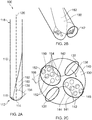
Figures 2A to 2C show respectively schematic elevational, partial perspective, and end views of a cutting tool according to an embodiment of the disclosure; and -
Figure 3 shows a schematic enlarged partial perspective view of a flank surface of the cutting tool ofFigures 2A to 2C ; -
Figure 4A shows a schematic representation of the action of the cutting edge of a conventional cutting tool; and -
Figure 4B shows a schematic representation of the action of the cutting edge and corresponding abrasive portion of the cutting tool ofFigures 2A to 2C . - It is noted that the drawings may not be to scale. The drawings are intended to depict only typical aspects of the disclosure, and therefore should not be considered as limiting the scope of the disclosure. In the drawings, like numbering represents like elements between the drawings.
- Referring to
Figures 2 and3 , a cutting tool according to an embodiment of the disclosure is designated generally by thereference numeral 100. - The
cutting tool 100 comprises atool body 110 having a first end 112 and an oppositesecond end 114. In the present embodiment, thetool body 110 has a generally cylindrical geometry. In other embodiments, thetool body 110 may have an alternative elongate geometry. Thetool body 110 has alongitudinal axis 120. - In the present embodiment the
second end 114 corresponds to a shank or holding portion (not shown) which would be used to hold thecutting tool 100 in a machine tool (not shown). - The first end 112 of the
tool body 110 has acentre region 114 and aperimetral edge 116. Thecentre region 114 of the first end 112 corresponds to the intersection of thelongitudinal axis 120 with the first end 112. Theperimetral edge 116 of the first end 112 corresponds to the circumferential edge of the first end 112 of thefirst end 110. - The first end 112 comprises two cutting
portions 130. In other embodiments the first end 112 may comprise more than two cuttingportions 130. - Each of the cutting
portions 130 comprises acutting edge 132 and acorresponding flank surface 140. Eachflank surface 140 extends circumferentially (direction 138) away from therespective cutting edge 132. - Each
cutting edge 132 extends radially outwardly from thecentre region 114 of the first end 112 to theperimetral edge 116 of the first end 112. Eachcutting edge 132 is oriented at anangle 134 relative to thelongitudinal axis 120. In the present embodiment, each cuttingedge 132 extends linearly from thecentre region 114 of the first end 112 to theperimetral edge 116 of the first end 112, with eachcutting edge 132 subtending afirst angle 136 with the longitudinal axis. - Each of the cutting edges 132 extends from the
perimetral edge 116 of the first end 112 towards thesecond end 118 along at least a part of thetool body 110 as atwisted flute 162. - At least two of the two or more flank surfaces 140 comprise an
abrasive portion 142 that extends over at least a part of therespective flank surface 140. In the case where the first end 112 comprises two cutting edges 132 (as in the present embodiment) then each one of the two corresponding flank surfaces 140 comprises anabrasive portion 142. In an alternative embodiment where the first end 112 comprises four cutting edges then either two, or all four, of the corresponding flank surfaces 140 may comprise anabrasive portion 142. - Each of the
abrasive portions 142 comprises a plurality ofabrasive features 144. The abrasive features 144 are arranged in tworows 150 across theflank surface 140. Each of the tworows 150 ofabrasive features 144 extends radially across theflank surface 140. Afirst row 152 ofabrasive features 144 is positioned at acircumferentially trailing edge 141 of theflank surface 140. - The
second row 154 ofabrasive features 144 is circumferentially (direction 138) offset from thefirst row 152. Theabrasive features 144 forming thesecond row 154 are also offset radially from theabrasive features 144 forming thefirst row 152. This radial offset 156 is arranged such that eachabrasive feature 144 in thesecond row 154 corresponds to the gaps between adjacent ones of theabrasive features 144 in thefirst row 152. - Each of the
abrasive features 144 has acircular plan section 146 and eachabrasive feature 144 extends from theflank surface 140 as aconical frustum 148. - Each
abrasive feature 144 extends from thecorresponding flank surface 140 by afeature height 158. Thefeature height 158 of eachabrasive feature 144 increases with radially distal feature position. In other words eachabrasive feature 144 has afeature height 158 that is greater than its radially proximal neighbour. - In the present embodiment the
cutting tool 100 is integrally formed from polycrystalline diamond. The process of forming the cutting edges 132, flank surfaces 140 andlongitudinal flutes 162 is known and is not described further herein. - The abrasive features 144 are formed integrally with the
flank surface 140 by selectively ablating a part of each of the flank surfaces 140. This selective ablation leaves the frustoconicalabrasive features 144 standing proud of theflank surface 140. The selective ablation process may be carried out by any suitable means such as, for example, a gas laser. - The abrasive features 144 may alternatively be formed by selectively modifying the flank surfaces 140 using electro-discharge machining. A further alternative arrangement may involve electroplating or brazing the
abrasive features 144 to the flank surfaces 140. - In an alternative embodiment where the
cutting tool 100 is formed from, say, a carbide material with a polycrystalline diamond coating being subsequently applied, the selective ablation process may be applied to the coating layer in the same manner as outlined above to produce the array ofabrasive features 144. - In use, the
abrasive portion 142 provides a supplementary cutting action and so reduces the cutting forces experienced by thecutting edge 132. This reduction in cutting force leads to a consequent reduction in the wear rate of thecutting edge 132. -
Figure 4A illustrates schematically the cutting action of a cutting tool 30 (in this case a twist drill) according to the prior art. The cuttingtool 30 comprises twocutting edges 32 and two flank surfaces 40. Eachflank surface 40 extends circumferentially away from a respective one of the cutting edges 32. - As the
cutting tool 30 meets a material 60 each cuttingedge 32 removes a portion of thematerial 60. This removed material has a depth hD that is referred to as the uncut chip thickness (or colloquially as the depth of cut). In thecutting tool 30 of the prior art the removal of material is performed entirely by the cutting edges 32. - In contrast,
Figure 4B shows a schematic illustration of the cutting action of thecutting tool 100 of the present disclosure. As shown inFigure 4B , and as described above, the removal of material is effected by both the cutting edges 132 and the abrasive features 144. - Each of the
abrasive features 144 removes a portion of material having a depth hgrid D, and each cutting edge removes a portion of material having a depth hedge D. Each of the cuttingedges 132 acts as aconventional cutting edge 32 of the prior art, and cuts along its entire linear length. Each of theabrasive features 144 removes material by a ploughing action as illustrated by the enlarged perspective view inFigure 4B of one such abrasive feature. In this way each of the cutting edges 132 performs less work then acutting edge 32 of the prior art and hence experiences a lower cutting force and a lower wear rate. - In one arrangement, each of the
abrasive features 144 has afeature height 158 that is equal to the depth of cut hedge D of the corresponding cutting edge. In other words, in this arrangement, the abrasive feature has a depth of cut hgrid D that is equal to the corresponding depth of cut hedge D of the corresponding cutting edge. - Although the aforementioned embodiments relate to the machining of CMC materials, it is to be understood that the positioning of abrasive features on the flank surfaces of a cutting tool may equally be applied to other cutting tool geometries and materials (i.e. coated and uncoated cemented carbide tools), and also to other machining processes (i.e. to turning inserts, or ball end milling cutters) commonly used for machining aerospace materials such as, for example, nickel and titanium alloy steels.
- Except where mutually exclusive, any of the features may be employed separately or in combination with any other features and the disclosure extends to and includes all combinations and sub-combinations of one or more features described herein.
- The foregoing description of various aspects of the disclosure has been presented for purposes of illustration and description. It is not intended to be exhaustive or to limit the disclosure to the precise form disclosed, and obviously, many modifications and variations are possible. Such modifications and variations that may be apparent to a person of skill in the art are included within the scope of the disclosure as defined by the accompanying claims.
forming an abrasive portion over at least a part of each of at least two of the two or more of the flank surfaces, with each abrasive portion comprising a plurality of abrasive features.
Claims (15)
- A cutting tool comprising:a tool body having a first end and a second end,the tool body having a longitudinal axis extending between the first end and the second end,the first end comprising two or more cutting portions,wherein each of the cutting portions comprises:a cutting edge extending radially outwardly from a centre region of the first end to a perimetral edge of the first end, the cutting edge being angled relative to the longitudinal axis; anda flank surface extending circumferentially from the cutting edge, characterised in that each of at least two of the two or more flank surfaces comprises an abrasive portion extending over at least a part of the respective flank surface, and each abrasive portion comprises a plurality of abrasive features.
- The cutting tool as claimed in in Claim 1, wherein the abrasive features have a circular profile.
- The cutting tool as claimed in Claim 1 or Claim 2, wherein the abrasive features extend from the flank surface as conical frusta.
- The cutting tool as claimed in any one of Claims 1 to 3, wherein the abrasive features are arranged in two adjacent rows across the flank surface, each row extending radially across the flank surface, the first row positioned adjacent to a circumferentially trailing edge of the flank surface, the second row being radially offset from the first row.
- The cutting tool as claimed in any one of Claims 1 to 4, wherein each abrasive feature extends from the flank surface by a feature height, the feature height increasing with radially distal feature position.
- The cutting tool as claimed in any one of Claims 1 to 5, wherein each cutting edge extends linearly from the centre region of the first end to a perimetral edge of the first end, each cutting edge subtending a first angle with the longitudinal axis.
- The cutting tool as claimed in any one of Claims 1 to 6, further comprising two or more flutes extending along at least a part of the tool body, and wherein each of the two or more cutting edges corresponds to a respective one of the two or more flutes.
- The cutting tool as claimed in any one of Claims 1 to 7, wherein the cutting tool is integrally formed from a material selected from the group consisting of diamond materials and cubic boron nitride materials.
- The cutting tool as claimed in any one of Claims 1 to 7, wherein the cutting tool is formed from a base material selected from the group consisting of steel, titanium, and carbide materials, and the base material is provided with a coating layer selected from the group consisting of diamond materials and cubic boron nitride materials.
- The cutting tool as claimed in any one of Claims 5 to 9, wherein the feature height of each abrasive feature is equal to the corresponding depth of the cut along the cutting edge.
- A method of forming a cutting tool, the method comprising the steps of:providing a tool body having a first end, a second end, and a longitudinal axis extending from the first end to the second end;forming two or more cutting portions at the first end, each cutting portion comprising a cutting edge and a flank surface, each cutting edge extending radially outwardly from a centre region of the first end to a perimetral edge of the first end, the cutting edge being angled relative to the longitudinal axis, and each flank surface extending circumferentially from the cutting edge;characterised in that the method comprises the further step of:
forming an abrasive portion over at least a part of each of at least two of the two or more of the flank surfaces, with each abrasive portion comprising a plurality of abrasive features. - The method as claimed in Claim 11, wherein the step of forming two or more cutting portions at the first end, comprises the additional step of:
forming two or more flutes along the tool body, each twisted flute corresponding to a respective one of the cutting portions, each flute extending from the perimetral edge of the first end along at least a part of the tool body. - The method as claimed in Claim 11 or Claim 12, wherein the tool body is formed from a diamond material, and the step of forming an abrasive portion over at least a part of each of at least two of the two or more of the flank surfaces, comprises the step of:
selectively creating (i.e. by laser ablating, electro-discharge machining, electroplating or brazing) a part of the flank surface on at least two of the two or more of the flank surfaces to generate a plurality of abrasive features extending from the flank surface. - The method as claimed in any one of Claims 11 to 13, wherein each abrasive feature extends from the flank surface by a feature height, the feature height increasing with radially distal feature position.
- The cutting tool as claimed in Claim 14, wherein the feature height of each abrasive feature is equal to the corresponding depth of the cut along the cutting edge.
Applications Claiming Priority (1)
| Application Number | Priority Date | Filing Date | Title |
|---|---|---|---|
| GBGB1706687.9A GB201706687D0 (en) | 2017-04-27 | 2017-04-27 | A cutting tool |
Publications (2)
| Publication Number | Publication Date |
|---|---|
| EP3395523A1 true EP3395523A1 (en) | 2018-10-31 |
| EP3395523B1 EP3395523B1 (en) | 2022-01-26 |
Family
ID=59011189
Family Applications (1)
| Application Number | Title | Priority Date | Filing Date |
|---|---|---|---|
| EP18168571.0A Active EP3395523B1 (en) | 2017-04-27 | 2018-04-20 | Cutting tool and method of forming a cutting tool |
Country Status (4)
| Country | Link |
|---|---|
| US (1) | US10618120B2 (en) |
| EP (1) | EP3395523B1 (en) |
| CN (1) | CN108788251B (en) |
| GB (1) | GB201706687D0 (en) |
Families Citing this family (4)
| Publication number | Priority date | Publication date | Assignee | Title |
|---|---|---|---|---|
| US11529689B2 (en) * | 2020-01-10 | 2022-12-20 | General Electric Company | Methods and apparatus for forming an aperture in a composite component |
| CN111666650B (en) * | 2020-04-22 | 2023-08-29 | 航天材料及工艺研究所 | A Matching Method of Cutting Parameters and Tool Parameters Based on Molded High Silica Milling |
| CN114571195A (en) * | 2021-12-29 | 2022-06-03 | 上海航天控制技术研究所 | Co-curing structure flywheel wheel body and manufacturing and processing method thereof |
| JP7366510B2 (en) * | 2022-03-14 | 2023-10-23 | 日東電工株式会社 | Composite cutting tool and method for manufacturing resin sheet using the same |
Citations (2)
| Publication number | Priority date | Publication date | Assignee | Title |
|---|---|---|---|---|
| US5022801A (en) * | 1990-07-18 | 1991-06-11 | The General Electric Company | CVD diamond coated twist drills |
| US20150314483A1 (en) * | 2014-04-30 | 2015-11-05 | Us Synthetic Corporation | Cutting tool assemblies including superhard working surfaces, material-removing machines including cutting tool assemblies, and methods of use |
Family Cites Families (34)
| Publication number | Priority date | Publication date | Assignee | Title |
|---|---|---|---|---|
| US3715788A (en) | 1971-03-01 | 1973-02-13 | Ingersoll Milling Machine Co | Rotary cutter with helical blades |
| US4176723A (en) | 1977-11-11 | 1979-12-04 | DTL, Incorporated | Diamond drill bit |
| JPS60177809A (en) | 1984-02-23 | 1985-09-11 | Sumitomo Electric Ind Ltd | Drill |
| SU1256886A2 (en) | 1985-03-25 | 1986-09-15 | Skochko Evgenij V | Twist bit |
| DE3544433C2 (en) * | 1985-12-16 | 1995-12-14 | Hilti Ag | Rock drill |
| US4721421A (en) | 1986-10-03 | 1988-01-26 | Brubaker Tool Corporation | Cutting tool with chip breakers |
| DE3730378A1 (en) | 1987-09-10 | 1989-03-23 | Micro Crystal Ag | CUTTING TOOL, ESPECIALLY DRILLING AND / OR MILLING |
| EP0320881B2 (en) | 1987-12-14 | 2003-10-22 | Mitsubishi Materials Corporation | Twist drill |
| US5265688A (en) * | 1990-04-09 | 1993-11-30 | Hilti Aktiengesellschaft | Rock drill |
| JPH0516010A (en) | 1991-07-08 | 1993-01-26 | Kobe Steel Ltd | Electro-deposition end mill |
| US5184925A (en) * | 1992-01-10 | 1993-02-09 | Kennametal Inc. | Insert and insert support bar |
| US5890552A (en) | 1992-01-31 | 1999-04-06 | Baker Hughes Incorporated | Superabrasive-tipped inserts for earth-boring drill bits |
| US5443337A (en) * | 1993-07-02 | 1995-08-22 | Katayama; Ichiro | Sintered diamond drill bits and method of making |
| GB9314954D0 (en) | 1993-07-16 | 1993-09-01 | Camco Drilling Group Ltd | Improvements in or relating to torary drill bits |
| JP3260764B2 (en) | 1995-06-07 | 2002-02-25 | サン‐ゴバン アブレイシブズ,インコーポレイティド | Cutting tools with patterned cutting surfaces |
| JPH0957515A (en) | 1995-08-17 | 1997-03-04 | Mitsubishi Materials Corp | Drill |
| US5913644A (en) | 1998-04-20 | 1999-06-22 | Kennametal Inc. | Helical mill having multiple flutes with differing rake angles |
| EP1923157B1 (en) | 2001-07-10 | 2020-07-29 | Mitsubishi Materials Corporation | Drill |
| JP2003251512A (en) | 2002-02-27 | 2003-09-09 | Kyocera Corp | Diamond tool and drilling method using the same |
| DE10351183A1 (en) * | 2003-11-03 | 2005-06-02 | Illinois Tool Works Inc., Glenview | rock drill |
| US7360608B2 (en) | 2004-09-09 | 2008-04-22 | Baker Hughes Incorporated | Rotary drill bits including at least one substantially helically extending feature and methods of operation |
| WO2007098159A2 (en) | 2006-02-23 | 2007-08-30 | Baker Hughes Incorporated | Backup cutting element insert for rotary drill bits |
| US7621699B2 (en) | 2006-07-11 | 2009-11-24 | Robert Bosch Gmbh | Abrasive coated fluted bit with recesses |
| US8590644B2 (en) | 2006-08-11 | 2013-11-26 | Schlumberger Technology Corporation | Downhole drill bit |
| WO2008091654A2 (en) | 2007-01-25 | 2008-07-31 | Baker Hughes Incorporated | Rotary drag bit |
| IL192785A0 (en) | 2007-10-22 | 2009-02-11 | Gershon Harif | Cutting tool with protrusions, and methods of use thereof |
| JP2010064173A (en) * | 2008-09-10 | 2010-03-25 | Covalent Materials Corp | Electrodeposition drill |
| AT12442U1 (en) * | 2010-05-26 | 2012-05-15 | Dywidag Systems Int Gmbh | drill bit |
| US9144845B1 (en) | 2012-03-01 | 2015-09-29 | The Boeing Company | Cutting tools with textured surfaces |
| US9162345B2 (en) * | 2012-06-08 | 2015-10-20 | Varel International Ind., L.P. | Drilling or abrading tool having a working surface with an array of blind apertures plugged with super-abrasive material |
| CN104439431A (en) * | 2014-11-26 | 2015-03-25 | 常州依丝特纺织服饰有限公司 | Conical drill bit |
| CN105983718A (en) * | 2015-02-16 | 2016-10-05 | 汪风珍 | Drill bit |
| GB201504759D0 (en) * | 2015-03-20 | 2015-05-06 | Rolls Royce Plc | Abrading tool for a rotary dresser |
| CN205949934U (en) * | 2016-08-08 | 2017-02-15 | 温州宝通机械制造有限公司 | Cutter head |
-
2017
- 2017-04-27 GB GBGB1706687.9A patent/GB201706687D0/en not_active Ceased
-
2018
- 2018-04-20 EP EP18168571.0A patent/EP3395523B1/en active Active
- 2018-04-24 US US15/960,940 patent/US10618120B2/en active Active
- 2018-04-27 CN CN201810392598.1A patent/CN108788251B/en active Active
Patent Citations (2)
| Publication number | Priority date | Publication date | Assignee | Title |
|---|---|---|---|---|
| US5022801A (en) * | 1990-07-18 | 1991-06-11 | The General Electric Company | CVD diamond coated twist drills |
| US20150314483A1 (en) * | 2014-04-30 | 2015-11-05 | Us Synthetic Corporation | Cutting tool assemblies including superhard working surfaces, material-removing machines including cutting tool assemblies, and methods of use |
Also Published As
| Publication number | Publication date |
|---|---|
| US20180311748A1 (en) | 2018-11-01 |
| GB201706687D0 (en) | 2017-06-14 |
| CN108788251B (en) | 2021-01-26 |
| CN108788251A (en) | 2018-11-13 |
| EP3395523B1 (en) | 2022-01-26 |
| US10618120B2 (en) | 2020-04-14 |
Similar Documents
| Publication | Publication Date | Title |
|---|---|---|
| US10618120B2 (en) | Cutting tool | |
| RU2470742C2 (en) | Rotary file containing hard alloy | |
| JP5473274B2 (en) | Grooving milling cutter for machining with high feed and low cutting depth | |
| CN108789863B (en) | Cutting tool | |
| US6290438B1 (en) | Reaming tool and process for its production | |
| JP5988314B2 (en) | How to make a through hole and countersink in a polycrystalline body | |
| JP6606840B2 (en) | Rotary cutting tool with polycrystalline diamond sintered body | |
| JPWO2010143595A1 (en) | Drilling tool | |
| US20160052069A1 (en) | Twist drill with ceramic inserts | |
| US20170021434A1 (en) | Method for producing a machining tool and machining tool | |
| JP2012020394A (en) | Edge-interchangeable rotary cutting tool | |
| US10343225B2 (en) | Monolithic ceramic end mill cutter set having a helix angle in the interval of 28° to 43° | |
| CN101801574A (en) | Tool consisting of sintered material and having only partial grinding | |
| US9694432B2 (en) | Drill reamer | |
| US11090739B2 (en) | End-mills made of hard metal and ceramic combined by brazing method | |
| JP4787910B2 (en) | Cemented carbide end mill and cutting method using the end mill | |
| CN205414508U (en) | Fibre reinforced composite makes spot facing cutter based on electrodeposited diamond | |
| CN101227995B (en) | Machine reamer | |
| CN211387180U (en) | Efficient unequal multi-blade reamer | |
| JP5302941B2 (en) | Roughing ball end mill | |
| JP3639227B2 (en) | Drilling tools for brittle materials | |
| CN118338979A (en) | Method for producing a drilling tool cutting segment and such a drilling tool cutting segment | |
| JP2008142834A (en) | Drill | |
| JP5939687B2 (en) | Cutting tools | |
| JP6080304B2 (en) | Cutting tools |
Legal Events
| Date | Code | Title | Description |
|---|---|---|---|
| PUAI | Public reference made under article 153(3) epc to a published international application that has entered the european phase |
Free format text: ORIGINAL CODE: 0009012 |
|
| STAA | Information on the status of an ep patent application or granted ep patent |
Free format text: STATUS: THE APPLICATION HAS BEEN PUBLISHED |
|
| AK | Designated contracting states |
Kind code of ref document: A1 Designated state(s): AL AT BE BG CH CY CZ DE DK EE ES FI FR GB GR HR HU IE IS IT LI LT LU LV MC MK MT NL NO PL PT RO RS SE SI SK SM TR |
|
| AX | Request for extension of the european patent |
Extension state: BA ME |
|
| STAA | Information on the status of an ep patent application or granted ep patent |
Free format text: STATUS: REQUEST FOR EXAMINATION WAS MADE |
|
| 17P | Request for examination filed |
Effective date: 20190426 |
|
| RBV | Designated contracting states (corrected) |
Designated state(s): AL AT BE BG CH CY CZ DE DK EE ES FI FR GB GR HR HU IE IS IT LI LT LU LV MC MK MT NL NO PL PT RO RS SE SI SK SM TR |
|
| RAP1 | Party data changed (applicant data changed or rights of an application transferred) |
Owner name: ROLLS-ROYCE PLC |
|
| REG | Reference to a national code |
Ref country code: DE Ref legal event code: R079 Ref document number: 602018029940 Country of ref document: DE Free format text: PREVIOUS MAIN CLASS: B28D0001140000 Ipc: B23B0051080000 |
|
| GRAP | Despatch of communication of intention to grant a patent |
Free format text: ORIGINAL CODE: EPIDOSNIGR1 |
|
| RIC1 | Information provided on ipc code assigned before grant |
Ipc: B23P 15/32 20060101ALN20211022BHEP Ipc: B23P 15/28 20060101ALI20211022BHEP Ipc: B28D 1/14 20060101ALI20211022BHEP Ipc: B23B 51/08 20060101AFI20211022BHEP |
|
| STAA | Information on the status of an ep patent application or granted ep patent |
Free format text: STATUS: GRANT OF PATENT IS INTENDED |
|
| GRAS | Grant fee paid |
Free format text: ORIGINAL CODE: EPIDOSNIGR3 |
|
| GRAA | (expected) grant |
Free format text: ORIGINAL CODE: 0009210 |
|
| STAA | Information on the status of an ep patent application or granted ep patent |
Free format text: STATUS: THE PATENT HAS BEEN GRANTED |
|
| INTG | Intention to grant announced |
Effective date: 20211202 |
|
| AK | Designated contracting states |
Kind code of ref document: B1 Designated state(s): AL AT BE BG CH CY CZ DE DK EE ES FI FR GB GR HR HU IE IS IT LI LT LU LV MC MK MT NL NO PL PT RO RS SE SI SK SM TR |
|
| REG | Reference to a national code |
Ref country code: GB Ref legal event code: FG4D |
|
| REG | Reference to a national code |
Ref country code: CH Ref legal event code: EP |
|
| REG | Reference to a national code |
Ref country code: AT Ref legal event code: REF Ref document number: 1464870 Country of ref document: AT Kind code of ref document: T Effective date: 20220215 |
|
| REG | Reference to a national code |
Ref country code: IE Ref legal event code: FG4D |
|
| REG | Reference to a national code |
Ref country code: DE Ref legal event code: R096 Ref document number: 602018029940 Country of ref document: DE |
|
| REG | Reference to a national code |
Ref country code: SE Ref legal event code: TRGR |
|
| REG | Reference to a national code |
Ref country code: LT Ref legal event code: MG9D |
|
| REG | Reference to a national code |
Ref country code: NL Ref legal event code: MP Effective date: 20220126 |
|
| REG | Reference to a national code |
Ref country code: AT Ref legal event code: MK05 Ref document number: 1464870 Country of ref document: AT Kind code of ref document: T Effective date: 20220126 |
|
| PG25 | Lapsed in a contracting state [announced via postgrant information from national office to epo] |
Ref country code: NL Free format text: LAPSE BECAUSE OF FAILURE TO SUBMIT A TRANSLATION OF THE DESCRIPTION OR TO PAY THE FEE WITHIN THE PRESCRIBED TIME-LIMIT Effective date: 20220126 |
|
| PG25 | Lapsed in a contracting state [announced via postgrant information from national office to epo] |
Ref country code: RS Free format text: LAPSE BECAUSE OF FAILURE TO SUBMIT A TRANSLATION OF THE DESCRIPTION OR TO PAY THE FEE WITHIN THE PRESCRIBED TIME-LIMIT Effective date: 20220126 Ref country code: PT Free format text: LAPSE BECAUSE OF FAILURE TO SUBMIT A TRANSLATION OF THE DESCRIPTION OR TO PAY THE FEE WITHIN THE PRESCRIBED TIME-LIMIT Effective date: 20220526 Ref country code: NO Free format text: LAPSE BECAUSE OF FAILURE TO SUBMIT A TRANSLATION OF THE DESCRIPTION OR TO PAY THE FEE WITHIN THE PRESCRIBED TIME-LIMIT Effective date: 20220426 Ref country code: LT Free format text: LAPSE BECAUSE OF FAILURE TO SUBMIT A TRANSLATION OF THE DESCRIPTION OR TO PAY THE FEE WITHIN THE PRESCRIBED TIME-LIMIT Effective date: 20220126 Ref country code: HR Free format text: LAPSE BECAUSE OF FAILURE TO SUBMIT A TRANSLATION OF THE DESCRIPTION OR TO PAY THE FEE WITHIN THE PRESCRIBED TIME-LIMIT Effective date: 20220126 Ref country code: ES Free format text: LAPSE BECAUSE OF FAILURE TO SUBMIT A TRANSLATION OF THE DESCRIPTION OR TO PAY THE FEE WITHIN THE PRESCRIBED TIME-LIMIT Effective date: 20220126 Ref country code: BG Free format text: LAPSE BECAUSE OF FAILURE TO SUBMIT A TRANSLATION OF THE DESCRIPTION OR TO PAY THE FEE WITHIN THE PRESCRIBED TIME-LIMIT Effective date: 20220426 |
|
| PG25 | Lapsed in a contracting state [announced via postgrant information from national office to epo] |
Ref country code: PL Free format text: LAPSE BECAUSE OF FAILURE TO SUBMIT A TRANSLATION OF THE DESCRIPTION OR TO PAY THE FEE WITHIN THE PRESCRIBED TIME-LIMIT Effective date: 20220126 Ref country code: LV Free format text: LAPSE BECAUSE OF FAILURE TO SUBMIT A TRANSLATION OF THE DESCRIPTION OR TO PAY THE FEE WITHIN THE PRESCRIBED TIME-LIMIT Effective date: 20220126 Ref country code: GR Free format text: LAPSE BECAUSE OF FAILURE TO SUBMIT A TRANSLATION OF THE DESCRIPTION OR TO PAY THE FEE WITHIN THE PRESCRIBED TIME-LIMIT Effective date: 20220427 Ref country code: FI Free format text: LAPSE BECAUSE OF FAILURE TO SUBMIT A TRANSLATION OF THE DESCRIPTION OR TO PAY THE FEE WITHIN THE PRESCRIBED TIME-LIMIT Effective date: 20220126 Ref country code: AT Free format text: LAPSE BECAUSE OF FAILURE TO SUBMIT A TRANSLATION OF THE DESCRIPTION OR TO PAY THE FEE WITHIN THE PRESCRIBED TIME-LIMIT Effective date: 20220126 |
|
| PG25 | Lapsed in a contracting state [announced via postgrant information from national office to epo] |
Ref country code: IS Free format text: LAPSE BECAUSE OF FAILURE TO SUBMIT A TRANSLATION OF THE DESCRIPTION OR TO PAY THE FEE WITHIN THE PRESCRIBED TIME-LIMIT Effective date: 20220526 |
|
| REG | Reference to a national code |
Ref country code: DE Ref legal event code: R097 Ref document number: 602018029940 Country of ref document: DE |
|
| PG25 | Lapsed in a contracting state [announced via postgrant information from national office to epo] |
Ref country code: SM Free format text: LAPSE BECAUSE OF FAILURE TO SUBMIT A TRANSLATION OF THE DESCRIPTION OR TO PAY THE FEE WITHIN THE PRESCRIBED TIME-LIMIT Effective date: 20220126 Ref country code: SK Free format text: LAPSE BECAUSE OF FAILURE TO SUBMIT A TRANSLATION OF THE DESCRIPTION OR TO PAY THE FEE WITHIN THE PRESCRIBED TIME-LIMIT Effective date: 20220126 Ref country code: RO Free format text: LAPSE BECAUSE OF FAILURE TO SUBMIT A TRANSLATION OF THE DESCRIPTION OR TO PAY THE FEE WITHIN THE PRESCRIBED TIME-LIMIT Effective date: 20220126 Ref country code: EE Free format text: LAPSE BECAUSE OF FAILURE TO SUBMIT A TRANSLATION OF THE DESCRIPTION OR TO PAY THE FEE WITHIN THE PRESCRIBED TIME-LIMIT Effective date: 20220126 Ref country code: DK Free format text: LAPSE BECAUSE OF FAILURE TO SUBMIT A TRANSLATION OF THE DESCRIPTION OR TO PAY THE FEE WITHIN THE PRESCRIBED TIME-LIMIT Effective date: 20220126 Ref country code: CZ Free format text: LAPSE BECAUSE OF FAILURE TO SUBMIT A TRANSLATION OF THE DESCRIPTION OR TO PAY THE FEE WITHIN THE PRESCRIBED TIME-LIMIT Effective date: 20220126 |
|
| PG25 | Lapsed in a contracting state [announced via postgrant information from national office to epo] |
Ref country code: AL Free format text: LAPSE BECAUSE OF FAILURE TO SUBMIT A TRANSLATION OF THE DESCRIPTION OR TO PAY THE FEE WITHIN THE PRESCRIBED TIME-LIMIT Effective date: 20220126 |
|
| REG | Reference to a national code |
Ref country code: CH Ref legal event code: PL |
|
| PLBE | No opposition filed within time limit |
Free format text: ORIGINAL CODE: 0009261 |
|
| STAA | Information on the status of an ep patent application or granted ep patent |
Free format text: STATUS: NO OPPOSITION FILED WITHIN TIME LIMIT |
|
| GBPC | Gb: european patent ceased through non-payment of renewal fee |
Effective date: 20220426 |
|
| 26N | No opposition filed |
Effective date: 20221027 |
|
| REG | Reference to a national code |
Ref country code: BE Ref legal event code: MM Effective date: 20220430 |
|
| PG25 | Lapsed in a contracting state [announced via postgrant information from national office to epo] |
Ref country code: MC Free format text: LAPSE BECAUSE OF FAILURE TO SUBMIT A TRANSLATION OF THE DESCRIPTION OR TO PAY THE FEE WITHIN THE PRESCRIBED TIME-LIMIT Effective date: 20220126 Ref country code: LU Free format text: LAPSE BECAUSE OF NON-PAYMENT OF DUE FEES Effective date: 20220420 Ref country code: LI Free format text: LAPSE BECAUSE OF NON-PAYMENT OF DUE FEES Effective date: 20220430 Ref country code: GB Free format text: LAPSE BECAUSE OF NON-PAYMENT OF DUE FEES Effective date: 20220426 Ref country code: CH Free format text: LAPSE BECAUSE OF NON-PAYMENT OF DUE FEES Effective date: 20220430 |
|
| PG25 | Lapsed in a contracting state [announced via postgrant information from national office to epo] |
Ref country code: SI Free format text: LAPSE BECAUSE OF FAILURE TO SUBMIT A TRANSLATION OF THE DESCRIPTION OR TO PAY THE FEE WITHIN THE PRESCRIBED TIME-LIMIT Effective date: 20220126 Ref country code: BE Free format text: LAPSE BECAUSE OF NON-PAYMENT OF DUE FEES Effective date: 20220430 |
|
| PG25 | Lapsed in a contracting state [announced via postgrant information from national office to epo] |
Ref country code: IE Free format text: LAPSE BECAUSE OF NON-PAYMENT OF DUE FEES Effective date: 20220420 |
|
| P01 | Opt-out of the competence of the unified patent court (upc) registered |
Effective date: 20230528 |
|
| PG25 | Lapsed in a contracting state [announced via postgrant information from national office to epo] |
Ref country code: IT Free format text: LAPSE BECAUSE OF FAILURE TO SUBMIT A TRANSLATION OF THE DESCRIPTION OR TO PAY THE FEE WITHIN THE PRESCRIBED TIME-LIMIT Effective date: 20220126 |
|
| PG25 | Lapsed in a contracting state [announced via postgrant information from national office to epo] |
Ref country code: HU Free format text: LAPSE BECAUSE OF FAILURE TO SUBMIT A TRANSLATION OF THE DESCRIPTION OR TO PAY THE FEE WITHIN THE PRESCRIBED TIME-LIMIT; INVALID AB INITIO Effective date: 20180420 |
|
| PG25 | Lapsed in a contracting state [announced via postgrant information from national office to epo] |
Ref country code: MK Free format text: LAPSE BECAUSE OF FAILURE TO SUBMIT A TRANSLATION OF THE DESCRIPTION OR TO PAY THE FEE WITHIN THE PRESCRIBED TIME-LIMIT Effective date: 20220126 Ref country code: CY Free format text: LAPSE BECAUSE OF FAILURE TO SUBMIT A TRANSLATION OF THE DESCRIPTION OR TO PAY THE FEE WITHIN THE PRESCRIBED TIME-LIMIT Effective date: 20220126 |
|
| PG25 | Lapsed in a contracting state [announced via postgrant information from national office to epo] |
Ref country code: MT Free format text: LAPSE BECAUSE OF FAILURE TO SUBMIT A TRANSLATION OF THE DESCRIPTION OR TO PAY THE FEE WITHIN THE PRESCRIBED TIME-LIMIT Effective date: 20220126 |
|
| PGFP | Annual fee paid to national office [announced via postgrant information from national office to epo] |
Ref country code: DE Payment date: 20250428 Year of fee payment: 8 |
|
| PGFP | Annual fee paid to national office [announced via postgrant information from national office to epo] |
Ref country code: FR Payment date: 20250424 Year of fee payment: 8 |
|
| PGFP | Annual fee paid to national office [announced via postgrant information from national office to epo] |
Ref country code: SE Payment date: 20250424 Year of fee payment: 8 |
|
| PG25 | Lapsed in a contracting state [announced via postgrant information from national office to epo] |
Ref country code: TR Free format text: LAPSE BECAUSE OF FAILURE TO SUBMIT A TRANSLATION OF THE DESCRIPTION OR TO PAY THE FEE WITHIN THE PRESCRIBED TIME-LIMIT Effective date: 20220126 |