EP3395466A1 - Roll stamping apparatus and method - Google Patents
Roll stamping apparatus and method Download PDFInfo
- Publication number
- EP3395466A1 EP3395466A1 EP16879345.3A EP16879345A EP3395466A1 EP 3395466 A1 EP3395466 A1 EP 3395466A1 EP 16879345 A EP16879345 A EP 16879345A EP 3395466 A1 EP3395466 A1 EP 3395466A1
- Authority
- EP
- European Patent Office
- Prior art keywords
- molding
- rollers
- portions
- sets
- roll
- Prior art date
- Legal status (The legal status is an assumption and is not a legal conclusion. Google has not performed a legal analysis and makes no representation as to the accuracy of the status listed.)
- Granted
Links
Images









Classifications
-
- B—PERFORMING OPERATIONS; TRANSPORTING
- B21—MECHANICAL METAL-WORKING WITHOUT ESSENTIALLY REMOVING MATERIAL; PUNCHING METAL
- B21D—WORKING OR PROCESSING OF SHEET METAL OR METAL TUBES, RODS OR PROFILES WITHOUT ESSENTIALLY REMOVING MATERIAL; PUNCHING METAL
- B21D53/00—Making other particular articles
- B21D53/88—Making other particular articles other parts for vehicles, e.g. cowlings, mudguards
-
- B—PERFORMING OPERATIONS; TRANSPORTING
- B21—MECHANICAL METAL-WORKING WITHOUT ESSENTIALLY REMOVING MATERIAL; PUNCHING METAL
- B21D—WORKING OR PROCESSING OF SHEET METAL OR METAL TUBES, RODS OR PROFILES WITHOUT ESSENTIALLY REMOVING MATERIAL; PUNCHING METAL
- B21D5/00—Bending sheet metal along straight lines, e.g. to form simple curves
- B21D5/14—Bending sheet metal along straight lines, e.g. to form simple curves by passing between rollers
-
- B—PERFORMING OPERATIONS; TRANSPORTING
- B21—MECHANICAL METAL-WORKING WITHOUT ESSENTIALLY REMOVING MATERIAL; PUNCHING METAL
- B21D—WORKING OR PROCESSING OF SHEET METAL OR METAL TUBES, RODS OR PROFILES WITHOUT ESSENTIALLY REMOVING MATERIAL; PUNCHING METAL
- B21D22/00—Shaping without cutting, by stamping, spinning, or deep-drawing
- B21D22/02—Stamping using rigid devices or tools
-
- B—PERFORMING OPERATIONS; TRANSPORTING
- B21—MECHANICAL METAL-WORKING WITHOUT ESSENTIALLY REMOVING MATERIAL; PUNCHING METAL
- B21D—WORKING OR PROCESSING OF SHEET METAL OR METAL TUBES, RODS OR PROFILES WITHOUT ESSENTIALLY REMOVING MATERIAL; PUNCHING METAL
- B21D5/00—Bending sheet metal along straight lines, e.g. to form simple curves
- B21D5/06—Bending sheet metal along straight lines, e.g. to form simple curves by drawing procedure making use of dies or forming-rollers, e.g. making profiles
- B21D5/08—Bending sheet metal along straight lines, e.g. to form simple curves by drawing procedure making use of dies or forming-rollers, e.g. making profiles making use of forming-rollers
- B21D5/083—Bending sheet metal along straight lines, e.g. to form simple curves by drawing procedure making use of dies or forming-rollers, e.g. making profiles making use of forming-rollers for obtaining profiles with changing cross-sectional configuration
-
- B—PERFORMING OPERATIONS; TRANSPORTING
- B21—MECHANICAL METAL-WORKING WITHOUT ESSENTIALLY REMOVING MATERIAL; PUNCHING METAL
- B21D—WORKING OR PROCESSING OF SHEET METAL OR METAL TUBES, RODS OR PROFILES WITHOUT ESSENTIALLY REMOVING MATERIAL; PUNCHING METAL
- B21D11/00—Bending not restricted to forms of material mentioned in only one of groups B21D5/00, B21D7/00, B21D9/00; Bending not provided for in groups B21D5/00 - B21D9/00; Twisting
- B21D11/20—Bending sheet metal, not otherwise provided for
Definitions
- a stamping method is most widely used, and such a stamping method includes an upper die, a lower punch disposed below the upper die, and a material holder disposed between the upper die and the lower punch.
- the upper die is a mold member having a groove portion formed in a lower surface thereof, wherein the groove portion is fitted to a shape of an article to be molded
- the lower punch is a member disposed below the upper die and is driven upwardly to thereby upwardly push a material moving between the upper die and the lower punch to press the material onto the upper die.
- stamping method is a technology which is widely used to produce the molded articles, for example, parts of the automobile, but in recent years, there are a problem in which capacity of the apparatus should be increased in an application of high-strength steel, and a problem in that the material is broken due to vulnerable moldability of the high strength steel.
- the roll forming method is configured so that a set of multistage fixed upper and lower rotating rolls is arranged and a coil or a cut material passes therebetween, and molds a molded article, a part having a long length while having a constant cross-section shape.
- the present disclosure provides a roll stamping method and apparatus to achieve the above-mentioned object.
- the set of over-molding rollers may be disposed within at least three sets of rollers of the final set of rollers.
- the molding portion may include an intaglio formed in an outer surface of a rotation roll of one roller of the set of rollers and having both sides opened, and an embossment formed in an outer surface of a rotation roll of the other roller thereof and corresponding to the intaglio.
- the molding portions of the sets of rollers may perform planarization for a cross section of the material by sequentially forming a concave-convex portion on the cross section of the material or removing the concave-convex portion from the cross section of the material in the movement direction of the material.
- the molding portions of the sets of rollers may perform planarization for a cross section of the material by sequentially removing a concave-convex portion from the cross section of the material
- the molding portions of the final set of rollers and the set of over-molding rollers may include flat portions which are flat in a width direction and have a predetermined length in a circumferential direction, and transition portions positioned at both sides of the flat portion in the circumferential direction, and a length of the flat portion of the set of over-molding rollers in the circumferential direction may be longer than a length of the flat portion of the final set of rollers in the circumferential direction.
- the escape portions may be formed in opposite sides of the molding portions and may be concave in an inner diameter direction from outer circumferential surfaces of the rollers.
- a roll stamping method includes a plurality of molding steps of molding a material which is continuously supplied, through stamping structures formed on outer surfaces of sets of rollers; and a cutting step of cutting the molded material, wherein the material passes through the plurality of molding steps such that a portion thereof is changed from a first shape to a second shape, and the plurality of molding steps include a reverse deformation molding step, opposite to a deformed direction in which the material is deformed from the first shape to the second shape.
- both end portions of a molded portion of the material in a length direction may be reversely deformed.
- the reverse deformation molding step may be performed in the final molding steps.
- the both end portions may be reversely deformed in the reverse deformation molding step by molding a molding portion of the material to be longer than a target molding portion, before the reverse deformation molding step.
- the roll stamping apparatus and method may reduce the undesirable shape by solving the residual stress of the cross section changing portion and the unbalance of force between the cross section changing portions.
- FIGS. 1 and 2 illustrate the conventional roll stamping apparatus and a product molded by the conventional roll stamping apparatus.
- a plurality of roller sets 10, 20, 30, and 40 are disposed in a movement direction of a material
- each of the roller sets 10, 20, 30, and 40 includes an upper roll 10a and a lower roll 10b
- molding portions 11a and 11b are formed in each of the rolls 10a and 10b to mold the material.
- Each of the roller sets 10, 20, 30, and 40 includes the molding portion, and sequentially changes the molding portion along the movement direction of the material as illustrated in FIG. 1 to mold a portion of the material from a first shape before molding to a second shape different from the first shape.
- An object of the present disclosure is to reduce the undesirable shape of the product by removing the residual stress remaining in the transition portions or at least preventing the transition portions from being distorted, and FIG. 3 illustrating a roll stamping apparatus according to the present disclosure for achieving the above-mentioned object.
- the roll stamping apparatus may include sets of rollers 10, 20, 40, and 50 rotating while facing each other so as to press opposite surfaces of a material S, continuously supplied to move between the rollers, and molding portions 11a, 11b, 41a, 41b, 51a, and 51b having a stamping structure applied to outer surfaces of the sets of rollers 10, 20, 40, and 50 so as to mold the material, wherein a plurality of sets of rollers 10, 20, 40, and 50 are disposed in a movement direction of the material, the respective molding portions of the sets of rollers are formed to sequentially change a cross section of the material in the movement direction of the material, and the molding portions 51a and 51b of at least one set of rollers of the sets of rollers before a final set of rollers through which the material finally passes is a set of over-molding rollers 40 having a length in a circumferential direction longer than the molding portions 41a and 41b of the final set of rollers 40.
- the cross section of the material may be sequentially changed from a hat shape (a first shape) to a flat shape (a second shape) by the molding portions.
- FIG. 4A is a plan view of the material passing through a first set of rollers 10, wherein some regions 101, 102, and 103 of the material which had the hat-shaped cross section are molded. Transition portions 102 and 103 may be formed between an unmolded region and a flat portion 101 with respect to the flat portion 101 having a flat outer surface on the plan view among the molded regions.
- the flat portion 101 of FIG. 4A refers to a region having the same cross section in the movement direction of the material regardless the flat cross section thereof, and the transition portions 102 and 103 refer to regions in which a cross section is changed along the movement direction of the material.
- FIG. 7B illustrates a photograph of a material molded by the roll stamping apparatus according the present disclosure. As illustrated in FIG. 7B, in a case in which the material is molded by the roll stamping apparatus according to the present disclosure, it may be seen that the material is attached to the bottom without being distorted.
- the roll stamping apparatus includes sets of rollers 10, 20, 40, and 50 having the same molding portions as the exemplary embodiment illustrated in FIG. 3, but there is a difference in that the sets of rollers 10, 20, 40, and 50 have escape portions 15a, 15b, 25a, 25b, 45a, 45b, 55a, and 55b formed on surfaces opposite to the respective molding portions.
- the escape portions 15a, 15b, 25a, 25b, 45a, 45b, 55a, and 55b are configurations formed to be concave inwardly from a circumference of the rolls, and are formed on the opposite sides of the molding portions 11a, 11b, 41a, 41b, 51a, and 51b.
- the sets of rollers 10, 20, 40, and 50 since the sets of rollers 10, 20, 40, and 50 have the escape portions 15a, 15b, 25a, 25b, 45a, 45b, 55a, and 55b formed together with the molding portions 11a, 11b, 41a, 41b, 51a, and 51b, the sets of rollers 10, 20, 40, and 50 may mold the material S in the predetermined sections and bypass the material S in the predetermined section.
Landscapes
- Engineering & Computer Science (AREA)
- Mechanical Engineering (AREA)
- Bending Of Plates, Rods, And Pipes (AREA)
- Press Drives And Press Lines (AREA)
- Shaping Metal By Deep-Drawing, Or The Like (AREA)
Abstract
Description
- The present disclosure relates to a roll stamping apparatus including a rotating roll having a molding portion by which a stamped structure is applied to an outer surface, and a roll stamping method.
- In general, numerous sheet metal molding technologies have been developed to produce parts applied to an automobile, or the like.
- First, a stamping method is most widely used, and such a stamping method includes an upper die, a lower punch disposed below the upper die, and a material holder disposed between the upper die and the lower punch. Here, the upper die is a mold member having a groove portion formed in a lower surface thereof, wherein the groove portion is fitted to a shape of an article to be molded, and the lower punch is a member disposed below the upper die and is driven upwardly to thereby upwardly push a material moving between the upper die and the lower punch to press the material onto the upper die.
- Such a stamping method is a technology which is widely used to produce the molded articles, for example, parts of the automobile, but in recent years, there are a problem in which capacity of the apparatus should be increased in an application of high-strength steel, and a problem in that the material is broken due to vulnerable moldability of the high strength steel.
- Next, a roll forming (RF) method is used. The roll forming method is configured so that a set of multistage fixed upper and lower rotating rolls is arranged and a coil or a cut material passes therebetween, and molds a molded article, a part having a long length while having a constant cross-section shape.
- The roll forming method by the rolling forming apparatus as described above may be applied to the high strength steel by utilizing an apparatus having relatively small capacity, but has a limitation in that only a molded article having the constant cross-section shape may be produced.
- Accordingly, a roll stamping method as disclosed in Patent Document 1 has been developed. In the roll stamping method, since a stamped structure is applied to a rotating roll which is rotated, the roll stamping method is a method of performing variable cross section roll forming while the material passes through the rotating roll.
- However, in the roll stamping method as described above, there is a problem in that an undesirable shape, such as a distortion or the like, due to residual stress of a cross section changing portion and unbalance of force between the respective cross section changing portions within a part, may occur.
- (Patent Document 1)
KR1417278 B - An aspect of the present disclosure is to provide a roll stamping apparatus and method that do not have an undesirable shape by solving residual stress of a cross section changing portion and unbalance of force between the cross section changing portions.
- The present disclosure provides a roll stamping method and apparatus to achieve the above-mentioned object.
- According to an aspect of the present disclosure, a roll stamping apparatus includes sets of rollers rotating while facing each other so as to press opposite surfaces of a material which is continuously supplied to move between the rollers; and molding portions having a stamping structure applied to outer surfaces of the sets of rollers so as to mold the material, wherein a plurality of sets of rollers are disposed in a movement direction of the material, the respective molding portions of the sets of rollers are formed to sequentially change a cross section of the material in the movement direction of the material, and the molding portion of at least one set of rollers of the sets of rollers before a final set of rollers through which the material finally passes is a set of over-molding rollers having a length in a circumferential direction longer than the molding portions of the final set of rollers.
- The set of over-molding rollers may be disposed within at least three sets of rollers of the final set of rollers.
- The molding portion may include an intaglio formed in an outer surface of a rotation roll of one roller of the set of rollers and having both sides opened, and an embossment formed in an outer surface of a rotation roll of the other roller thereof and corresponding to the intaglio.
- The molding portions of the sets of rollers may perform planarization for a cross section of the material by sequentially forming a concave-convex portion on the cross section of the material or removing the concave-convex portion from the cross section of the material in the movement direction of the material.
- The molding portions of the sets of rollers may perform planarization for a cross section of the material by sequentially removing a concave-convex portion from the cross section of the material, the molding portions of the final set of rollers and the set of over-molding rollers may include flat portions which are flat in a width direction and have a predetermined length in a circumferential direction, and transition portions positioned at both sides of the flat portion in the circumferential direction, and a length of the flat portion of the set of over-molding rollers in the circumferential direction may be longer than a length of the flat portion of the final set of rollers in the circumferential direction.
- Escape portions through which the material passes may be formed in the positions different from the molding portions in the outer surfaces of the sets of rollers.
- The escape portions may be formed in opposite sides of the molding portions and may be concave in an inner diameter direction from outer circumferential surfaces of the rollers.
- According to another aspect of the present disclosure, a roll stamping method includes a plurality of molding steps of molding a material which is continuously supplied, through stamping structures formed on outer surfaces of sets of rollers; and a cutting step of cutting the molded material, wherein the material passes through the plurality of molding steps such that a portion thereof is changed from a first shape to a second shape, and the plurality of molding steps include a reverse deformation molding step, opposite to a deformed direction in which the material is deformed from the first shape to the second shape.
- In the reverse deformation molding step, both end portions of a molded portion of the material in a length direction may be reversely deformed.
- The reverse deformation molding step may be performed in the final molding steps.
- The both end portions may be reversely deformed in the reverse deformation molding step by molding a molding portion of the material to be longer than a target molding portion, before the reverse deformation molding step.
- The roll stamping method may further include, after the plurality of molding steps, bypassing the material to escape portions formed in the sets of rollers, wherein after the bypassing of the material, the plurality of molding steps may be reperformed, and a ratio of a supply speed of the material to revolutions per minute of the sets of rollers in the plurality of molding steps may be different from that in the bypassing of the material.
- As set forth above, according to an exemplary embodiment in the present disclosure, the roll stamping apparatus and method may reduce the undesirable shape by solving the residual stress of the cross section changing portion and the unbalance of force between the cross section changing portions.
-
- FIG. 1 is a view illustrating a conventional roll stamping apparatus.
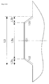
- FIG. 2 is a plan view of a product manufactured by the conventional roll stamping apparatus.
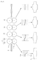
- FIG. 3 is a view illustrating a roll stamping apparatus according to the present disclosure.
- FIGS. 4A through 4D are plan views for each of the steps of a product manufactured by the roll stamping apparatus according to the present disclosure.
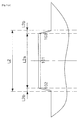
- FIGS. 5A and 5B are plan views illustrating a final shape of the product manufactured by the roll stamping apparatus and a shape of a product molded in an over-molding roller set according to the present disclosure.
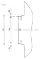
- FIGS. 6A and 6B are plan views illustrating a final shape of the product manufactured by the roll stamping apparatus and a shape of another product molded in an over-molding roller set according to the present disclosure.
- FIGS. 7A and 7B are photographs of a product molded by the conventional roll stamping apparatus and a product molded by the roll stamping apparatus according to the present disclosure.
- FIGS. 8 and 9 are views illustrating a roll stamping apparatus according to another exemplary embodiment in the present disclosure.
- FIG. 10 is a side view of a product molded by the roll stamping apparatus of FIGS. 8 and 9.
- Hereinafter, exemplary embodiments in the present disclosure will be described with reference to the accompanying drawings.
- FIGS. 1 and 2 illustrate the conventional roll stamping apparatus and a product molded by the conventional roll stamping apparatus. As illustrated in FIG. 1, in the conventional roll stamping apparatus, a plurality of
roller sets roller sets upper roll 10a and alower roll 10b, and moldingportions rolls - Each of the
roller sets - The product molded by the roll stamping apparatus described above may include transition portions T1 and T2 which are changed to portions (cross sections A-A and C-C) having a first shape and a portion (a cross section B-B) molded by the molding portion and having a second shape. The above-mentioned transition portions T1 and T2 may have residual stress that exists in directions opposite to each other, and have a problem in that the transition portions are distorted when being cut into the product or before being cut into the product.
- An object of the present disclosure is to reduce the undesirable shape of the product by removing the residual stress remaining in the transition portions or at least preventing the transition portions from being distorted, and FIG. 3 illustrating a roll stamping apparatus according to the present disclosure for achieving the above-mentioned object.
- As illustrated in FIG. 3, the roll stamping apparatus according to the present disclosure may include sets of
rollers portions rollers rollers molding portions rollers 40 having a length in a circumferential direction longer than themolding portions rollers 40. - FIGS. 4A through 4D are plan views for each of the steps of a material molded by the roll stamping apparatus of FIG. 3, wherein FIG. 4A is a plan view of the material molded by the set of
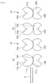
rollers 10 of FIG. 3, FIG. 4B is a plan view of the material molded by the set ofrollers 20 of FIG. 3, FIG. 4C is a plan view of the material molded by the over-molding set ofrollers 50 of FIG. 3, and FIG. 4D is a plan view of the material molded by the final set ofrollers 40 of FIG. 3. - As illustrated in FIGS. 4A through 4D, as the material S passes through the sets of
rollers - Here, the shape of the material or the number of the sets of rollers is merely an example, the number of the sets of rollers may be increased or decreased as needed, and the material may have a shape corresponding to a desired product. In addition, although FIGS. 4A through 4D illustrate a case in which the material has the same width before being molded, the width of the material may also be cut before the material is roll-stamped.
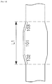
- FIG. 4A is a plan view of the material passing through a first set of
rollers 10, wherein someregions Transition portions flat portion 101 with respect to theflat portion 101 having a flat outer surface on the plan view among the molded regions. Theflat portion 101 of FIG. 4A refers to a region having the same cross section in the movement direction of the material regardless the flat cross section thereof, and thetransition portions - FIG. 4B is a plan view of the material passing through a second set of
rollers 20, wherein someregions rollers 20 and the first set ofrollers 10 perform the molding for the regions having the same length (L1=L2). - FIG. 4C is a plan view of the material passing through the over-molding set of
rollers 50. Someregions rollers 50 is longer than that of the material passing through the second set ofrollers 20, lengths of themolding portions rollers 50 in a circumferential direction may be longer than lengths of themolding portions rollers - FIG. 4D is a plan view of the material passing through the over-molding set of
rollers 50 and then passing through the final set ofrollers 40 to have a desired second shape. As illustrated in FIG. 4D, since the final set ofrollers 40 molds the over-molded material to a target shape by again reversely molding the over-molded material, a length L4 of a material molding region may be smaller than a length L3 of a material molding region passing through the over-molding set of rollers (L3<L4). Accordingly, thetransition portions return portions - Accordingly, since the
transition portions return portions - In FIGS. 4A through 4D, although it is illustrated and described that one set of
over-molding rollers 50 is disposed immediately before the final set ofrollers 40, the set ofover-molding rollers 50 is not limited thereto and a plurality of sets of rollers before the final set ofrollers 40 may be formed as the sets ofover-molding rollers 50. - In addition, the set of
over-molding rollers 50 may include a case in which the length in the length direction of the material, that is, the length in the circumferential direction of the roll is longer than the lengths of the molding portions of the final set of rollers in the circumferential direction, and may also include a case in which since a degree of the material molded by the set of over-molding rollers is greater than that molded by the molding portions of the final set of rollers, the material is changed in a reverse direction to become the second shape, the target shape (the material does not change from the first shape to the second shape but changes to a third shape that is a shape beyond the second shape and then to the second shape) again. - The roll stamping apparatus according to the present disclosure may also be applied to a roll stamping method corresponding thereto. Since the distortion of the material becomes more problematic when the material is cut, the roll stamping method according to the present disclosure may include a plurality of molding steps of molding a material which is continuously supplied, through stamping structures formed on outer surfaces of the sets of
rollers over-molding rollers 50 and then passes through the final set of rollers 40), which is opposite to a deformed direction in which the material is deformed from the first shape to the second shape. - In this case, if the material is again molded in the molding direction in which the material is molded from the first shape to the second shape after the reverse deformation molding step, since the residual stress is increased in the directions opposite to each other in the
transition portions - In addition, the residual stress of the
transition portions transition portions transition portions - FIGS. 5 and 6 illustrate plan views showing a final shape of a product manufactured by the roll stamping apparatus and a shape of a material molded by the set of over-molding rollers according to the present disclosure, respectively.
- In both FIGS. 5 and 6, a length L2 of a region molded by the second set of rollers may be shorter than a length L3 of a region molded by the set of over-molding rollers (L2<L3) .
- In FIG. 5, lengths L2b and L3b of the
transition portions flat portion 101, the length of theflat portion 101 of the set of over-molding rollers may be longer than the length of the flat portion of the second set of rollers by an increased length of the molded region (L3a>L2a). That is, the set of over-molding rollers may mold the material in a way in which an entire length of the molded region is increased by increasing the length of theflat portion 101 without changing the shape of thetransition portions rollers 40 and thetransition portions - In FIG. 6, lengths L3a and L2a of the
flat portion 101 may be equal to each other after the flat portion passes through the second set of rollers and after the flat portion passes through the set of over-molding rollers (L2a=L3a), but with respect to lengths L2b and L3b of thetransition portions transition portions - The set of over-molding rollers may mold the material in a way in which an entire length of the molded region is increased by increasing the lengths of the
transition portions flat portion 101, and the over-molded material as described above may be returned to a target molding length L4 in the final set ofrollers 40 and some of thetransition portions return portions 105 and 106 (see FIG. 4). During this process, a reverse molding may occur. - FIG. 7A illustrates a photograph of a material molded by the conventional roll stamping apparatus. As illustrated in FIG. 7A, the material is not attached to a bottom and is distorted. That is, in a case in which the material is molded by the conventional roll stamping apparatus, the distortion has occurred in the material due to residual stress in directions opposite to each other in a plurality of transition portions.
- FIG. 7B illustrates a photograph of a material molded by the roll stamping apparatus according the present disclosure. As illustrated in FIG. 7B, in a case in which the material is molded by the roll stamping apparatus according to the present disclosure, it may be seen that the material is attached to the bottom without being distorted.
- FIGS. 8 and 9 illustrate a roll stamping apparatus according to another exemplary embodiment in the present disclosure.
- The roll stamping apparatus according to another exemplary embodiment illustrated in FIGS. 8 and 9 includes sets of
rollers rollers escape portions - According to the present exemplary embodiment, the
escape portions molding portions - As illustrated in FIG. 9, the
escape portions rollers rollers escape portions - According to the present exemplary embodiment, since the sets of
rollers escape portions molding portions rollers - In particular, since the sets of
rollers escape portions - FIG. 10 illustrates the material S molded according to the exemplary embodiment of FIGS. 8 and 9. In the molded sections L4 and L6, when a supply speed (m/min) of the material S is constant, revolutions per minute (rev/min) of the sets of
rollers escape portions rollers - Accordingly, a product in which a length of a roll forming portion according to the present exemplary embodiment is diverse may also be manufactured. In particular, in the case of a configuration such as a door impact beam in which the molded section is constant and a length thereof is diverse, one roll stamping apparatus may mold door impact beams having various different lengths.
- Hereinabove, although the exemplary embodiments in the present disclosure have been described, the present disclosure is not limited thereto and may be variously changed and used.
Claims (16)
- A roll stamping apparatus comprising:sets of rollers rotating while facing each other so as to press opposite surfaces of a material which is continuously supplied to move between the rollers; andmolding portions having a stamping structure applied to outer surfaces of the sets of rollers so as to mold the material,wherein a plurality of sets of rollers are disposed in a movement direction of the material,the respective molding portions of the sets of rollers are formed to sequentially change a cross section of the material in the movement direction of the material, andat least one of the sets of rollers before a final set of rollers through which the material finally passes is a set of over-molding rollers having molding portions of which a length in a circumferential direction is longer than a length of the molding portions of the final set of rollers.
- The roll stamping apparatus of claim 1, wherein the set of over-molding rollers is disposed within at least three sets of rollers of the final set of rollers.
- The roll stamping apparatus of claim 1 or 2, wherein the molding portion includes an intaglio formed in an outer surface of a rotation roll of one roller of the set of rollers and having both sides opened, and an embossment formed in an outer surface of a rotation roll of the other roller thereof and corresponding to the intaglio.
- The roll stamping apparatus of claim 3, wherein the molding portions of the sets of rollers perform planarization for a cross section of the material by sequentially forming a concave-convex portion on the cross section of the material or removing the concave-convex portion from the cross section of the material in the movement direction of the material.
- The roll stamping apparatus of claim 1 or 2, wherein the molding portions of the sets of rollers perform planarization for a cross section of the material by sequentially removing a concave-convex portion from the cross section of the material,
the molding portions of the final set of rollers and the set of over-molding rollers include flat portions which are flat in a width direction and have a predetermined length in a circumferential direction, and transition portions positioned at both sides of the flat portion in the circumferential direction, and
a length of the flat portion of the set of over-molding rollers in the circumferential direction is longer than a length of the flat portion of the final set of rollers in the circumferential direction. - The roll stamping apparatus of claim 1 or 2, wherein the molding portion of the set of over-molding rollers includes a flat portion which is flat in a width direction and has a predetermined length in a circumferential direction, and transition portions positioned at both sides of the flat portion in the circumferential direction, and
a length of the transition portion of the set of over-molding rollers in the circumferential direction is longer than a length of the transition portion of the final set of rollers in the circumferential direction. - The roll stamping apparatus of claim 1, wherein escape portions through which the material passes are formed in positions different from the molding portions on the outer surfaces of the sets of rollers.
- The roll stamping apparatus of claim 7, wherein the escape portions are formed in the opposite sides of the molding portions.
- The roll stamping apparatus of claim 8, wherein the escape portions are concave in an inner diameter direction from outer circumferential surfaces of the rollers.
- A roll stamping method comprising:a plurality of molding steps of molding a material which is continuously supplied, through stamping structures formed on outer surfaces of sets of rollers; anda cutting step of cutting the molded material,wherein the material passes through the plurality of molding steps such that a portion thereof is changed from a first shape to a second shape, andthe plurality of molding steps include a reverse deformation molding step, which is opposite to a deformed direction in which the material is deformed from the first shape to the second shape.
- The roll stamping method of claim 10, wherein in the reverse deformation molding step, at least both end portions of a molding portion of the material in a length direction are reversely deformed.
- The roll stamping method of claim 10, wherein the reverse deformation molding step is performed after the middle of the entire molding steps.
- The roll stamping method of claim 10, wherein the both end portions are reversely deformed in the reverse deformation molding step by molding a molding portion of the material to be longer than a target molding portion, before the reverse deformation molding step.
- The roll stamping method of claim 11, wherein a molding portion of the material is reversely molded to a second shape in the reverse deformation molding step by molding the molding portion of the material to be beyond the second shape before the reverse deformation molding step.
- The roll stamping method of claim 10, further comprising, after the plurality of molding steps, bypassing the material to escape portions formed in the sets of rollers,
wherein after the bypassing of the material, the plurality of molding steps are reperformed. - The roll stamping method of claim 15, wherein a ratio of a supply speed of the material to revolutions per minute of the sets of rollers in the plurality of molding steps is different from that in the bypassing of the material.
Applications Claiming Priority (2)
| Application Number | Priority Date | Filing Date | Title |
|---|---|---|---|
| KR1020150185116A KR101786260B1 (en) | 2015-12-23 | 2015-12-23 | Roll Stamping Device |
| PCT/KR2016/015055 WO2017111478A1 (en) | 2015-12-23 | 2016-12-21 | Roll stamping apparatus and method |
Publications (3)
| Publication Number | Publication Date |
|---|---|
| EP3395466A1 true EP3395466A1 (en) | 2018-10-31 |
| EP3395466A4 EP3395466A4 (en) | 2019-05-08 |
| EP3395466B1 EP3395466B1 (en) | 2021-06-23 |
Family
ID=59089559
Family Applications (1)
| Application Number | Title | Priority Date | Filing Date |
|---|---|---|---|
| EP16879345.3A Active EP3395466B1 (en) | 2015-12-23 | 2016-12-21 | Roll stamping apparatus |
Country Status (6)
| Country | Link |
|---|---|
| US (2) | US11358200B2 (en) |
| EP (1) | EP3395466B1 (en) |
| JP (1) | JP6678241B2 (en) |
| KR (1) | KR101786260B1 (en) |
| CN (1) | CN108430663B (en) |
| WO (1) | WO2017111478A1 (en) |
Families Citing this family (2)
| Publication number | Priority date | Publication date | Assignee | Title |
|---|---|---|---|---|
| KR102412105B1 (en) * | 2020-09-17 | 2022-06-22 | 주식회사 포스코 | Apparatus for roll stamping |
| KR20230090587A (en) * | 2021-12-15 | 2023-06-22 | 주식회사 포스코 | Impact reinforcement component and method for manufacturing thereof |
Family Cites Families (25)
| Publication number | Priority date | Publication date | Assignee | Title |
|---|---|---|---|---|
| US180930A (en) * | 1876-08-08 | Improvement in rolling sucker-rod joints | ||
| GB1297136A (en) * | 1969-06-20 | 1972-11-22 | ||
| JPS51111462A (en) * | 1975-03-26 | 1976-10-01 | Furukawa Electric Co Ltd | Method of producing deformed bar |
| US4006617A (en) * | 1975-11-24 | 1977-02-08 | The Boeing Company | Method and apparatus for roll forming tapered structural members |
| JPS5334664A (en) * | 1976-09-13 | 1978-03-31 | Hitachi Metals Ltd | Bend forming process |
| JPH0221141Y2 (en) * | 1985-04-09 | 1990-06-07 | ||
| JPH0756090Y2 (en) * | 1990-11-14 | 1995-12-25 | 日鐵建材工業株式会社 | Deep bending / bending back device |
| JP3302308B2 (en) * | 1997-12-03 | 2002-07-15 | 住友金属建材株式会社 | Strip steel plate stepping machine |
| JP3811309B2 (en) * | 1999-02-03 | 2006-08-16 | 松下電器産業株式会社 | Method of forming hemispherical protrusion and boss |
| JP4107485B2 (en) * | 2002-11-07 | 2008-06-25 | 日野自動車株式会社 | Roll forming equipment |
| JP4419716B2 (en) * | 2004-02-16 | 2010-02-24 | 株式会社デンソー | Press working method and press working apparatus |
| DE102007061475B3 (en) * | 2007-12-20 | 2009-09-24 | Kabushiki Kaisha Kobe Seiko Sho (Kobe Steel, Ltd.), Kobe | Method of producing formed components from high strength and ultra high strength steels |
| US20090205387A1 (en) * | 2008-02-16 | 2009-08-20 | Industrial Origami, Inc. | System for low-force roll folding and methods thereof |
| TWI438041B (en) * | 2008-09-30 | 2014-05-21 | Nippon Steel & Sumitomo Metal Corp | Forming simulation method, forming simulation apparatus, forming simuration program and media for storing the program, and forming method using the simulation result |
| EP2578328B1 (en) | 2010-05-25 | 2018-03-21 | Nippon Steel & Sumitomo Metal Corporation | Method for forming metal member having excellent shape freezing properties |
| US8573012B1 (en) * | 2011-08-18 | 2013-11-05 | Wallace S. Paulson | Indexing system for corrugated metal forming |
| JP5728334B2 (en) * | 2011-08-31 | 2015-06-03 | 新日鐵住金株式会社 | Press-formed product for vehicle body having excellent collision performance and method for producing the same |
| KR101417278B1 (en) * | 2012-05-25 | 2014-07-08 | 주식회사 포스코 | Apparatus for roll stamping |
| JP5388146B2 (en) * | 2012-07-30 | 2014-01-15 | 日新製鋼株式会社 | Roll forming method for channel cross-section material |
| JP5382267B1 (en) | 2012-09-24 | 2014-01-08 | 新日鐵住金株式会社 | Method for producing section steel whose cross-sectional shape changes in the longitudinal direction and roll forming apparatus |
| KR101439674B1 (en) * | 2012-12-21 | 2014-09-12 | 주식회사 포스코 | Apparatus and Method for roll stamping of hot blank |
| KR101449190B1 (en) * | 2012-12-21 | 2014-10-08 | 주식회사 포스코 | Method for manufacturing one body type high strength vehicle parts using md-rf process |
| JP6202189B2 (en) | 2014-03-04 | 2017-09-27 | 新日鐵住金株式会社 | Press molded product manufacturing method, press molded product manufacturing apparatus, mandrel |
| JP6196921B2 (en) | 2014-03-17 | 2017-09-13 | トヨタ車体株式会社 | Manufacturing method of press parts |
| CN104624744B (en) | 2015-02-12 | 2017-01-11 | 南京天润型钢有限公司 | Roller type continuous cold bending forming method for stainless steel car roof edge beam |
-
2015
- 2015-12-23 KR KR1020150185116A patent/KR101786260B1/en active Active
-
2016
- 2016-12-21 EP EP16879345.3A patent/EP3395466B1/en active Active
- 2016-12-21 JP JP2018532633A patent/JP6678241B2/en active Active
- 2016-12-21 US US16/065,748 patent/US11358200B2/en active Active
- 2016-12-21 WO PCT/KR2016/015055 patent/WO2017111478A1/en not_active Ceased
- 2016-12-21 CN CN201680075672.6A patent/CN108430663B/en active Active
-
2022
- 2022-05-24 US US17/752,459 patent/US11571729B2/en active Active
Also Published As
| Publication number | Publication date |
|---|---|
| US11358200B2 (en) | 2022-06-14 |
| JP6678241B2 (en) | 2020-04-08 |
| WO2017111478A1 (en) | 2017-06-29 |
| JP2019503869A (en) | 2019-02-14 |
| CN108430663B (en) | 2020-07-28 |
| KR101786260B1 (en) | 2017-10-18 |
| US20220331852A1 (en) | 2022-10-20 |
| EP3395466A4 (en) | 2019-05-08 |
| KR20170075880A (en) | 2017-07-04 |
| EP3395466B1 (en) | 2021-06-23 |
| US11571729B2 (en) | 2023-02-07 |
| CN108430663A (en) | 2018-08-21 |
| US20190009319A1 (en) | 2019-01-10 |
Similar Documents
| Publication | Publication Date | Title |
|---|---|---|
| US4310939A (en) | Method of producing semicircular washers having a projection to prevent rotation | |
| US11571729B2 (en) | Roll stamping apparatus and method | |
| US20120040205A1 (en) | Method for producing a press-quenched metal component | |
| KR101917450B1 (en) | Roll Stamping Device and Method | |
| EP2826573B1 (en) | Method for producing a holder | |
| EP2926921B1 (en) | Method of manufacturing a metal plate having a hole, external gear with a peripheral hole and method of manufacturing a metal plate | |
| WO2010125876A1 (en) | Method for manufacturing element for belt of continuously variable transmission | |
| CN106660099B (en) | Forming material manufacturing method and forming material | |
| JP4483365B2 (en) | Thrust cylindrical roller bearing cage and manufacturing method thereof | |
| KR102435358B1 (en) | A method for producing a rotationally symmetrical shaped article | |
| JP4923597B2 (en) | Method for forming cylindrical shaft product and mold | |
| KR20200035913A (en) | A mold device for manufacturing a cylindrical rolling element, and a manufacturing method for a cylindrical rolling element, a manufacturing method for a rolling bearing, a manufacturing method for a vehicle, and a manufacturing method for a mechanical device | |
| US20070125147A1 (en) | Method of forming a part | |
| KR102412105B1 (en) | Apparatus for roll stamping | |
| KR20050032451A (en) | Method and apparatus for manufacturing a release strip | |
| JP4924653B2 (en) | Manufacturing method of cylindrical shaft | |
| EP3110619B1 (en) | Method and apparatus for forming profiled articles | |
| US845711A (en) | Method of punching and bending pulley-arms. | |
| JP2004028270A (en) | Method of manufacturing cage for tapered roller bearing | |
| JP2645787B2 (en) | Circumferential groove forming method | |
| JPH10216880A (en) | Production of poly-v pulley | |
| RU2490085C1 (en) | Method of rotary forming | |
| WO2017033656A1 (en) | Roll forming method for metal material and roll forming device for metal material | |
| JPH0159041B2 (en) | ||
| JP2019084569A (en) | Demolding method |
Legal Events
| Date | Code | Title | Description |
|---|---|---|---|
| STAA | Information on the status of an ep patent application or granted ep patent |
Free format text: STATUS: THE INTERNATIONAL PUBLICATION HAS BEEN MADE |
|
| PUAI | Public reference made under article 153(3) epc to a published international application that has entered the european phase |
Free format text: ORIGINAL CODE: 0009012 |
|
| STAA | Information on the status of an ep patent application or granted ep patent |
Free format text: STATUS: REQUEST FOR EXAMINATION WAS MADE |
|
| 17P | Request for examination filed |
Effective date: 20180720 |
|
| AK | Designated contracting states |
Kind code of ref document: A1 Designated state(s): AL AT BE BG CH CY CZ DE DK EE ES FI FR GB GR HR HU IE IS IT LI LT LU LV MC MK MT NL NO PL PT RO RS SE SI SK SM TR |
|
| AX | Request for extension of the european patent |
Extension state: BA ME |
|
| RIC1 | Information provided on ipc code assigned before grant |
Ipc: B21D 22/02 20060101AFI20181220BHEP Ipc: B21D 5/08 20060101ALI20181220BHEP Ipc: B21D 53/88 20060101ALI20181220BHEP Ipc: B21D 5/14 20060101ALI20181220BHEP Ipc: B21D 11/20 20060101ALI20181220BHEP |
|
| DAV | Request for validation of the european patent (deleted) | ||
| DAX | Request for extension of the european patent (deleted) | ||
| A4 | Supplementary search report drawn up and despatched |
Effective date: 20190405 |
|
| RIC1 | Information provided on ipc code assigned before grant |
Ipc: B21D 11/20 20060101ALI20190401BHEP Ipc: B21D 22/02 20060101AFI20190401BHEP Ipc: B21D 53/88 20060101ALI20190401BHEP Ipc: B21D 5/08 20060101ALI20190401BHEP Ipc: B21D 5/14 20060101ALI20190401BHEP |
|
| STAA | Information on the status of an ep patent application or granted ep patent |
Free format text: STATUS: EXAMINATION IS IN PROGRESS |
|
| 17Q | First examination report despatched |
Effective date: 20200417 |
|
| GRAP | Despatch of communication of intention to grant a patent |
Free format text: ORIGINAL CODE: EPIDOSNIGR1 |
|
| STAA | Information on the status of an ep patent application or granted ep patent |
Free format text: STATUS: GRANT OF PATENT IS INTENDED |
|
| INTG | Intention to grant announced |
Effective date: 20210114 |
|
| GRAS | Grant fee paid |
Free format text: ORIGINAL CODE: EPIDOSNIGR3 |
|
| GRAA | (expected) grant |
Free format text: ORIGINAL CODE: 0009210 |
|
| STAA | Information on the status of an ep patent application or granted ep patent |
Free format text: STATUS: THE PATENT HAS BEEN GRANTED |
|
| AK | Designated contracting states |
Kind code of ref document: B1 Designated state(s): AL AT BE BG CH CY CZ DE DK EE ES FI FR GB GR HR HU IE IS IT LI LT LU LV MC MK MT NL NO PL PT RO RS SE SI SK SM TR |
|
| REG | Reference to a national code |
Ref country code: GB Ref legal event code: FG4D |
|
| REG | Reference to a national code |
Ref country code: CH Ref legal event code: EP |
|
| REG | Reference to a national code |
Ref country code: DE Ref legal event code: R096 Ref document number: 602016059810 Country of ref document: DE Ref country code: AT Ref legal event code: REF Ref document number: 1403860 Country of ref document: AT Kind code of ref document: T Effective date: 20210715 |
|
| REG | Reference to a national code |
Ref country code: IE Ref legal event code: FG4D |
|
| REG | Reference to a national code |
Ref country code: LT Ref legal event code: MG9D |
|
| PG25 | Lapsed in a contracting state [announced via postgrant information from national office to epo] |
Ref country code: BG Free format text: LAPSE BECAUSE OF FAILURE TO SUBMIT A TRANSLATION OF THE DESCRIPTION OR TO PAY THE FEE WITHIN THE PRESCRIBED TIME-LIMIT Effective date: 20210923 Ref country code: HR Free format text: LAPSE BECAUSE OF FAILURE TO SUBMIT A TRANSLATION OF THE DESCRIPTION OR TO PAY THE FEE WITHIN THE PRESCRIBED TIME-LIMIT Effective date: 20210623 Ref country code: FI Free format text: LAPSE BECAUSE OF FAILURE TO SUBMIT A TRANSLATION OF THE DESCRIPTION OR TO PAY THE FEE WITHIN THE PRESCRIBED TIME-LIMIT Effective date: 20210623 Ref country code: LT Free format text: LAPSE BECAUSE OF FAILURE TO SUBMIT A TRANSLATION OF THE DESCRIPTION OR TO PAY THE FEE WITHIN THE PRESCRIBED TIME-LIMIT Effective date: 20210623 |
|
| REG | Reference to a national code |
Ref country code: AT Ref legal event code: MK05 Ref document number: 1403860 Country of ref document: AT Kind code of ref document: T Effective date: 20210623 |
|
| PG25 | Lapsed in a contracting state [announced via postgrant information from national office to epo] |
Ref country code: LV Free format text: LAPSE BECAUSE OF FAILURE TO SUBMIT A TRANSLATION OF THE DESCRIPTION OR TO PAY THE FEE WITHIN THE PRESCRIBED TIME-LIMIT Effective date: 20210623 Ref country code: GR Free format text: LAPSE BECAUSE OF FAILURE TO SUBMIT A TRANSLATION OF THE DESCRIPTION OR TO PAY THE FEE WITHIN THE PRESCRIBED TIME-LIMIT Effective date: 20210924 Ref country code: RS Free format text: LAPSE BECAUSE OF FAILURE TO SUBMIT A TRANSLATION OF THE DESCRIPTION OR TO PAY THE FEE WITHIN THE PRESCRIBED TIME-LIMIT Effective date: 20210623 Ref country code: SE Free format text: LAPSE BECAUSE OF FAILURE TO SUBMIT A TRANSLATION OF THE DESCRIPTION OR TO PAY THE FEE WITHIN THE PRESCRIBED TIME-LIMIT Effective date: 20210623 Ref country code: NO Free format text: LAPSE BECAUSE OF FAILURE TO SUBMIT A TRANSLATION OF THE DESCRIPTION OR TO PAY THE FEE WITHIN THE PRESCRIBED TIME-LIMIT Effective date: 20210923 |
|
| REG | Reference to a national code |
Ref country code: NL Ref legal event code: MP Effective date: 20210623 |
|
| PG25 | Lapsed in a contracting state [announced via postgrant information from national office to epo] |
Ref country code: EE Free format text: LAPSE BECAUSE OF FAILURE TO SUBMIT A TRANSLATION OF THE DESCRIPTION OR TO PAY THE FEE WITHIN THE PRESCRIBED TIME-LIMIT Effective date: 20210623 Ref country code: CZ Free format text: LAPSE BECAUSE OF FAILURE TO SUBMIT A TRANSLATION OF THE DESCRIPTION OR TO PAY THE FEE WITHIN THE PRESCRIBED TIME-LIMIT Effective date: 20210623 Ref country code: AT Free format text: LAPSE BECAUSE OF FAILURE TO SUBMIT A TRANSLATION OF THE DESCRIPTION OR TO PAY THE FEE WITHIN THE PRESCRIBED TIME-LIMIT Effective date: 20210623 Ref country code: ES Free format text: LAPSE BECAUSE OF FAILURE TO SUBMIT A TRANSLATION OF THE DESCRIPTION OR TO PAY THE FEE WITHIN THE PRESCRIBED TIME-LIMIT Effective date: 20210623 Ref country code: PT Free format text: LAPSE BECAUSE OF FAILURE TO SUBMIT A TRANSLATION OF THE DESCRIPTION OR TO PAY THE FEE WITHIN THE PRESCRIBED TIME-LIMIT Effective date: 20211025 Ref country code: RO Free format text: LAPSE BECAUSE OF FAILURE TO SUBMIT A TRANSLATION OF THE DESCRIPTION OR TO PAY THE FEE WITHIN THE PRESCRIBED TIME-LIMIT Effective date: 20210623 Ref country code: NL Free format text: LAPSE BECAUSE OF FAILURE TO SUBMIT A TRANSLATION OF THE DESCRIPTION OR TO PAY THE FEE WITHIN THE PRESCRIBED TIME-LIMIT Effective date: 20210623 Ref country code: SK Free format text: LAPSE BECAUSE OF FAILURE TO SUBMIT A TRANSLATION OF THE DESCRIPTION OR TO PAY THE FEE WITHIN THE PRESCRIBED TIME-LIMIT Effective date: 20210623 Ref country code: SM Free format text: LAPSE BECAUSE OF FAILURE TO SUBMIT A TRANSLATION OF THE DESCRIPTION OR TO PAY THE FEE WITHIN THE PRESCRIBED TIME-LIMIT Effective date: 20210623 |
|
| PG25 | Lapsed in a contracting state [announced via postgrant information from national office to epo] |
Ref country code: PL Free format text: LAPSE BECAUSE OF FAILURE TO SUBMIT A TRANSLATION OF THE DESCRIPTION OR TO PAY THE FEE WITHIN THE PRESCRIBED TIME-LIMIT Effective date: 20210623 |
|
| REG | Reference to a national code |
Ref country code: DE Ref legal event code: R097 Ref document number: 602016059810 Country of ref document: DE |
|
| PG25 | Lapsed in a contracting state [announced via postgrant information from national office to epo] |
Ref country code: DK Free format text: LAPSE BECAUSE OF FAILURE TO SUBMIT A TRANSLATION OF THE DESCRIPTION OR TO PAY THE FEE WITHIN THE PRESCRIBED TIME-LIMIT Effective date: 20210623 |
|
| PLBE | No opposition filed within time limit |
Free format text: ORIGINAL CODE: 0009261 |
|
| STAA | Information on the status of an ep patent application or granted ep patent |
Free format text: STATUS: NO OPPOSITION FILED WITHIN TIME LIMIT |
|
| 26N | No opposition filed |
Effective date: 20220324 |
|
| PG25 | Lapsed in a contracting state [announced via postgrant information from national office to epo] |
Ref country code: AL Free format text: LAPSE BECAUSE OF FAILURE TO SUBMIT A TRANSLATION OF THE DESCRIPTION OR TO PAY THE FEE WITHIN THE PRESCRIBED TIME-LIMIT Effective date: 20210623 |
|
| PG25 | Lapsed in a contracting state [announced via postgrant information from national office to epo] |
Ref country code: MC Free format text: LAPSE BECAUSE OF FAILURE TO SUBMIT A TRANSLATION OF THE DESCRIPTION OR TO PAY THE FEE WITHIN THE PRESCRIBED TIME-LIMIT Effective date: 20210623 Ref country code: IT Free format text: LAPSE BECAUSE OF FAILURE TO SUBMIT A TRANSLATION OF THE DESCRIPTION OR TO PAY THE FEE WITHIN THE PRESCRIBED TIME-LIMIT Effective date: 20210623 |
|
| REG | Reference to a national code |
Ref country code: CH Ref legal event code: PL |
|
| GBPC | Gb: european patent ceased through non-payment of renewal fee |
Effective date: 20211221 |
|
| REG | Reference to a national code |
Ref country code: DE Ref legal event code: R081 Ref document number: 602016059810 Country of ref document: DE Owner name: POSCO CO., LTD, POHANG-SI, KR Free format text: FORMER OWNER: POSCO, POHANG-SI, GYEONGSANGBUK-DO, KR Ref country code: DE Ref legal event code: R081 Ref document number: 602016059810 Country of ref document: DE Owner name: POSCO CO., LTD, POHANG- SI, KR Free format text: FORMER OWNER: POSCO, POHANG-SI, GYEONGSANGBUK-DO, KR Ref country code: DE Ref legal event code: R081 Ref document number: 602016059810 Country of ref document: DE Owner name: POSCO HOLDINGS INC., KR Free format text: FORMER OWNER: POSCO, POHANG-SI, GYEONGSANGBUK-DO, KR |
|
| REG | Reference to a national code |
Ref country code: BE Ref legal event code: MM Effective date: 20211231 |
|
| PG25 | Lapsed in a contracting state [announced via postgrant information from national office to epo] |
Ref country code: LU Free format text: LAPSE BECAUSE OF NON-PAYMENT OF DUE FEES Effective date: 20211221 Ref country code: IE Free format text: LAPSE BECAUSE OF NON-PAYMENT OF DUE FEES Effective date: 20211221 Ref country code: GB Free format text: LAPSE BECAUSE OF NON-PAYMENT OF DUE FEES Effective date: 20211221 |
|
| PG25 | Lapsed in a contracting state [announced via postgrant information from national office to epo] |
Ref country code: BE Free format text: LAPSE BECAUSE OF NON-PAYMENT OF DUE FEES Effective date: 20211231 |
|
| PG25 | Lapsed in a contracting state [announced via postgrant information from national office to epo] |
Ref country code: LI Free format text: LAPSE BECAUSE OF NON-PAYMENT OF DUE FEES Effective date: 20211231 Ref country code: CH Free format text: LAPSE BECAUSE OF NON-PAYMENT OF DUE FEES Effective date: 20211231 |
|
| REG | Reference to a national code |
Ref country code: DE Ref legal event code: R081 Ref document number: 602016059810 Country of ref document: DE Owner name: POSCO CO., LTD, POHANG-SI, KR Free format text: FORMER OWNER: POSCO HOLDINGS INC., SEOUL, KR Ref country code: DE Ref legal event code: R081 Ref document number: 602016059810 Country of ref document: DE Owner name: POSCO CO., LTD, POHANG- SI, KR Free format text: FORMER OWNER: POSCO HOLDINGS INC., SEOUL, KR |
|
| PG25 | Lapsed in a contracting state [announced via postgrant information from national office to epo] |
Ref country code: CY Free format text: LAPSE BECAUSE OF FAILURE TO SUBMIT A TRANSLATION OF THE DESCRIPTION OR TO PAY THE FEE WITHIN THE PRESCRIBED TIME-LIMIT Effective date: 20210623 |
|
| PG25 | Lapsed in a contracting state [announced via postgrant information from national office to epo] |
Ref country code: HU Free format text: LAPSE BECAUSE OF FAILURE TO SUBMIT A TRANSLATION OF THE DESCRIPTION OR TO PAY THE FEE WITHIN THE PRESCRIBED TIME-LIMIT; INVALID AB INITIO Effective date: 20161221 |
|
| PG25 | Lapsed in a contracting state [announced via postgrant information from national office to epo] |
Ref country code: MK Free format text: LAPSE BECAUSE OF FAILURE TO SUBMIT A TRANSLATION OF THE DESCRIPTION OR TO PAY THE FEE WITHIN THE PRESCRIBED TIME-LIMIT Effective date: 20210623 |
|
| PG25 | Lapsed in a contracting state [announced via postgrant information from national office to epo] |
Ref country code: MT Free format text: LAPSE BECAUSE OF FAILURE TO SUBMIT A TRANSLATION OF THE DESCRIPTION OR TO PAY THE FEE WITHIN THE PRESCRIBED TIME-LIMIT Effective date: 20210623 |
|
| PG25 | Lapsed in a contracting state [announced via postgrant information from national office to epo] |
Ref country code: TR Free format text: LAPSE BECAUSE OF FAILURE TO SUBMIT A TRANSLATION OF THE DESCRIPTION OR TO PAY THE FEE WITHIN THE PRESCRIBED TIME-LIMIT Effective date: 20210623 |
|
| PGFP | Annual fee paid to national office [announced via postgrant information from national office to epo] |
Ref country code: DE Payment date: 20251208 Year of fee payment: 10 |
|
| PGFP | Annual fee paid to national office [announced via postgrant information from national office to epo] |
Ref country code: FR Payment date: 20251209 Year of fee payment: 10 |