EP3393704B1 - Cutting tool holder with vibration-damping weight assembly - Google Patents
Cutting tool holder with vibration-damping weight assembly Download PDFInfo
- Publication number
- EP3393704B1 EP3393704B1 EP16820364.4A EP16820364A EP3393704B1 EP 3393704 B1 EP3393704 B1 EP 3393704B1 EP 16820364 A EP16820364 A EP 16820364A EP 3393704 B1 EP3393704 B1 EP 3393704B1
- Authority
- EP
- European Patent Office
- Prior art keywords
- weight
- aperture
- cutting tool
- tool holder
- holder
- Prior art date
- Legal status (The legal status is an assumption and is not a legal conclusion. Google has not performed a legal analysis and makes no representation as to the accuracy of the status listed.)
- Active
Links
Images

Classifications
-
- B—PERFORMING OPERATIONS; TRANSPORTING
- B23—MACHINE TOOLS; METAL-WORKING NOT OTHERWISE PROVIDED FOR
- B23B—TURNING; BORING
- B23B27/00—Tools for turning or boring machines; Tools of a similar kind in general; Accessories therefor
- B23B27/002—Tools for turning or boring machines; Tools of a similar kind in general; Accessories therefor with vibration damping means
-
- B—PERFORMING OPERATIONS; TRANSPORTING
- B23—MACHINE TOOLS; METAL-WORKING NOT OTHERWISE PROVIDED FOR
- B23B—TURNING; BORING
- B23B27/00—Tools for turning or boring machines; Tools of a similar kind in general; Accessories therefor
- B23B27/04—Cutting-off tools
-
- B—PERFORMING OPERATIONS; TRANSPORTING
- B23—MACHINE TOOLS; METAL-WORKING NOT OTHERWISE PROVIDED FOR
- B23B—TURNING; BORING
- B23B27/00—Tools for turning or boring machines; Tools of a similar kind in general; Accessories therefor
- B23B27/08—Cutting tools with blade- or disc-like main parts
-
- B—PERFORMING OPERATIONS; TRANSPORTING
- B23—MACHINE TOOLS; METAL-WORKING NOT OTHERWISE PROVIDED FOR
- B23B—TURNING; BORING
- B23B27/00—Tools for turning or boring machines; Tools of a similar kind in general; Accessories therefor
- B23B27/14—Cutting tools of which the bits or tips or cutting inserts are of special material
- B23B27/16—Cutting tools of which the bits or tips or cutting inserts are of special material with exchangeable cutting bits or cutting inserts, e.g. able to be clamped
- B23B27/1666—Cutting tools of which the bits or tips or cutting inserts are of special material with exchangeable cutting bits or cutting inserts, e.g. able to be clamped with plate-like cutting inserts clamped by a clamping member acting almost perpendicularly on chip-forming plane
-
- B—PERFORMING OPERATIONS; TRANSPORTING
- B23—MACHINE TOOLS; METAL-WORKING NOT OTHERWISE PROVIDED FOR
- B23B—TURNING; BORING
- B23B29/00—Holders for non-rotary cutting tools; Boring bars or boring heads; Accessories for tool holders
- B23B29/04—Tool holders for a single cutting tool
- B23B29/043—Tool holders for a single cutting tool with cutting-off, grooving or profile cutting tools, i.e. blade- or disc-like main cutting parts
-
- B—PERFORMING OPERATIONS; TRANSPORTING
- B23—MACHINE TOOLS; METAL-WORKING NOT OTHERWISE PROVIDED FOR
- B23B—TURNING; BORING
- B23B29/00—Holders for non-rotary cutting tools; Boring bars or boring heads; Accessories for tool holders
- B23B29/04—Tool holders for a single cutting tool
- B23B29/12—Special arrangements on tool holders
-
- B—PERFORMING OPERATIONS; TRANSPORTING
- B23—MACHINE TOOLS; METAL-WORKING NOT OTHERWISE PROVIDED FOR
- B23B—TURNING; BORING
- B23B2205/00—Fixation of cutting inserts in holders
- B23B2205/02—Fixation using an elastically deformable clamping member
-
- B—PERFORMING OPERATIONS; TRANSPORTING
- B23—MACHINE TOOLS; METAL-WORKING NOT OTHERWISE PROVIDED FOR
- B23B—TURNING; BORING
- B23B2250/00—Compensating adverse effects during turning, boring or drilling
- B23B2250/16—Damping of vibrations
Definitions
- the present invention relates to cutting tool holders, in general, and to cutting tool holder blades with a weight aperture and vibration damping mechanisms, in particular.
- Cutting tool holders especially of the blade holder type, have a cutting insert located at a front end thereof. Performing cutting operations at the front end of the holder blade may cause unwanted vibrations at the cutting end.
- Cutting tool holders with vibration damping mechanisms are shown, for example, in JP2011042007A (which discloses a cutting tool holder according to the preamble of independent claim 1), JP2003062703A , US6113319 and KR101258519 .
- the present invention relates to a cutting tool holder 20 comprising a holder body 22 with a generally elongated shape and a longitudinal axis A1, and a weight aperture 30.
- a weight assembly 24 may be retained in the weight aperture 30.
- the holder body 22 has opposing first and second side surfaces 26a, 26b and a top surface 28 extending therebetween, and with the weight aperture 30 opening out to the first and second side surfaces 26a, 26b.
- the weight assembly 24 is located within the weight aperture 30.
- the weight aperture 30 may have a non-circular shape.
- the weight aperture 30 may have a generally parallelogrammatic shape.
- an insert mounting portion 32 is located at a front end 34 of the holder body 22 adjacent to the top surface 28.
- the holder body 22 may include a bottom surface 36 extending between the first and second side surfaces 26a, 26b opposite the top surface 28.
- the top and bottom surfaces 28, 36 may include upper and lower abutment surfaces 38, 40, respectively, extending parallel to the longitudinal axis A1 , facilitating assembly of the cutting tool holder 20 into an elongated tool block (not shown) having parallel extending retaining grooves.
- the weight aperture 30 may be located adjacent to the front end 34 of the holder body 22.
- the weight aperture 30 may be at least partially located in a bottom protuberance 42 extending downwardly from the lower abutment surface 40.
- the upper and lower abutment surfaces 38, 40 may define parallel first and second imaginary straight lines L1, L2, respectively, and the second imaginary straight line L2 may intersect the weight aperture 30.
- the provision of the bottom protuberance 42 enables the weight aperture 30 and the insert mounting portion 32 to be sufficiently spaced apart, so that the elongated holder body 22 retains an adequately high level of stiffness.
- the weight aperture 30 has an aperture inner surface 44, and an aperture axis A2 extending transversely to the longitudinal axis A1.
- the weight aperture 30 may exhibit mirror symmetry about a first plane P1 containing the aperture axis A2.
- the aperture axis A2 may be located below the second imaginary line L2.
- the first plane P1 may form an acute aperture angle ⁇ with the longitudinal axis A1 and not intersect the top surface 28.
- the aperture angle ⁇ may have a value of greater than 25° and less than 65°.
- the weight assembly 24 comprises:
- the first and second weight portions 46, 48 may be formed of a material denser than the material of the holder body 22.
- the first and second weight portions 46, 48 may be formed of hard metal, tungsten, and the like.
- the damping ring 50 may be formed of an elastic compressible material, such as rubber.
- a cutting insert 54 is retained in the insert mounting portion 32 of the holder body 22, for performing cutting operations on a workpiece, e.g., turning, grooving or parting.
- the holder body 22 may be prone to vibrations and chatter, which disturbs the engagement of the cutting insert 54 with the workpiece, and which may damage the cutting operation or the surface quality of the workpiece.
- the weight assembly 24 acts as a Dynamic Vibration Absorber (DVA) or a Tuned Mass Damper (TMD) for the holder body 22, by increasing the weight of its front end 34, wherein the damping ring 50 acts as a spring and the weight portions 46, 48 act together as the damping mass.
- the weight assembly 24 may thus be referred to as a vibration damping weight assembly 24. Vibrations of the holder body 22 are transferred through the damping ring 50 to the weight portions 46, 48, which, in turn, counteract to damp the vibrations of the holder body 22.
- each of the first and second weight portions 46, 48 may exhibit mirror symmetry about the first plane P1. It is noted that the first and second weight portions 46, 48 may not be necessarily identical, and may differ in weight or thickness.
- the damping ring 50 may be an O-ring, suitable for location along the aperture inner surface 44 of the non-circular shaped weight aperture 30.
- a second plane P2 perpendicular to the longitudinal axis A1 may intersect the cutting insert 54 and at least one of the first and second weight portions 46, 48.
- the second plane P2 may intersect the cutting insert 54 and both of the first and second weight portions 46, 48.
- the actuating member 52 may be rotatable about an actuating axis A3 contained in the first plane P1.
- the actuating axis A3 may be perpendicular to aperture axis A2.
- the actuating member 52 may comprise a central portion 56 located between two cylindrical-shaped end portions 58, 60.
- a first of the two end portions 58 may engage a first bore 62 in the first weight portion 46, and a second of the two end portions 60 may engage a second bore 64 in the second weight portion 48.
- the actuating axis A3 may be coaxial with the first and second bores 62, 64.
- At least one of the first and second end portions 58, 60 may threadingly engage the respective first and second bores 62, 64.
- the two end portions 58, 60 may have threads of opposite hand, and both of the first and second end portions 58, 60 may threadingly engage the respective first and second bores 62, 64.
- the central portion 56 may include a socket 66, or other means of rotation.
- the first and second weight portions 46, 48 are floating within the weight aperture 30, and apart from interfacing with the actuating member 52, the first and second weight portions 46, 48 are only in contact with the damping ring 50.
- the first and second weight portions 46, 48 do not contact the aperture inner surface 44.
- the damping ring 50 is restrained between the first and second weight portions 46, 48 and the aperture inner surface 44.
- the entire weight assembly 24 is restrained within the weight aperture 30, prevented from falling out therefrom.
- the amount to which the actuating member 52 is rotated in the first or second directions D1, D2 about the actuating axis A3 affects the amount to which the damping ring 50 is elastically compressed against the aperture inner surface 44. This also affects the extent of contact between the first and second weight portions 46, 48 and the damping ring 50, and between the damping ring 50 and the aperture inner surface 44. In the DVA aspect of the weight assembly 24, this fine tuning determines the spring constant of the damping ring 50.
- the weight aperture 30 may exhibit mirror symmetry about a third plane P3 containing the aperture axis A2 and perpendicular to the first plane P1.
- the first and second weight portions 46, 48 may be entirely located on opposite sides of the third plane P3.
- an inner groove 68 may continuously extend along the aperture inner surface 44, and the damping ring 50 may interface with the inner groove 68.
- the inner groove 68 may be V-shaped when viewed in a cross-section containing the aperture axis A2.
- the aperture inner surface 44 may be inclined at a first slope angle ⁇ 1 with respect to the aperture axis A2, to aid removal and replacement of the weight assembly 24.
- the first slope angle ⁇ 1 may have a value of less than 15°.
- both of the first and second weight portions 46, 48 may have a triangular shape, defined by three peripheral surfaces 70a, 70b, 70c; 72a, 72b, 72c extending between three corners 74a, 74b, 74c; 76a, 76b, 76c.
- first and second peripheral surfaces 70a, 70b; 72a, 72b diverging away from respective first corners 74a, 76a of the first and second weight portions 46, 48 may form acute first corner angles ⁇
- the first plane P1 may bisect each of the first corners 74a, 76a.
- each of the first corners 74a, 76a may have a curved corner peripheral surface 78, 80 located between the associated first and second peripheral surfaces 70a, 70b; 72a, 72b.
- the weight of the weight assembly 24, and in particular the weight of each of the first and second weight portions 46, 48, as well as the shape and dimension of the first and second weight portions 46, 48, are determined according to the shape and dimensions of the holder body 22, and according to the cutting operations to be performed with the cutting tool holder 20.
- the characteristics of the weight assembly 24 may change in different cutting tool holders.
- the cutting tool holder 20 may be used with different weight assemblies 24.
- first and second outer grooves 82a, 82b; 84a, 84b may extend along the first and second peripheral surfaces 70a, 70b; 72a, 72b, respectively, of both of the first and second weight portions 46, 48, and the damping ring 50 may interface with each of the first and second outer grooves 82a, 82b; 84a, 84b.
- each of the first and second outer grooves 82a, 82b; 84a, 84b may be V-shaped when viewed in a cross-section containing the aperture axis A2.
- each of the first and second peripheral surfaces 70a, 70b; 72a, 72b may be inclined at a second slope angle ⁇ 2 with respect to the aperture axis A2
- the second slope angle ⁇ 2 may be equal to the first slope angle ⁇ 1 .
- each of the first and second weight portions 46, 48 may have a maximum weight thickness TW MAX in the direction of the aperture axis A2, and the maximum weight thickness TW MAX may be less than or equal to the minimum thickness TA MIN of the holder body 22 at the weight aperture 30, so that the weight assembly 24 does not protrude beyond the first and second side surfaces 26a, 26b.
- the holder body 22 may be blade-shaped, having a maximum body thickness TB MAX between the first and second side surfaces 26a, 26b equal to the maximum thickness TA MAX of the holder body 22 at the weight aperture 30.
Landscapes
- Engineering & Computer Science (AREA)
- Mechanical Engineering (AREA)
- Cutting Tools, Boring Holders, And Turrets (AREA)
- Milling Processes (AREA)
- Vibration Prevention Devices (AREA)
- Auxiliary Devices For Machine Tools (AREA)
- Jigs For Machine Tools (AREA)
Description
- The present invention relates to cutting tool holders, in general, and to cutting tool holder blades with a weight aperture and vibration damping mechanisms, in particular.
- Cutting tool holders, especially of the blade holder type, have a cutting insert located at a front end thereof. Performing cutting operations at the front end of the holder blade may cause unwanted vibrations at the cutting end.
- Cutting tool holders with vibration damping mechanisms are shown, for example, in
JP2011042007A JP2003062703A US6113319 andKR101258519 - It is an object of the present invention to provide a cutting tool holder with an improved vibration damping mechanism.
- It is also an object of the present invention to provide a cutting tool holder with an improved vibration damping mechanism that can be easily removed and replaced.
- It is a further object of the present invention to provide a cutting tool holder with an improved vibration damping mechanism that can be tuned in its assembled position.
- In accordance with one aspect of the present invention, there is provided a cutting tool holder according to
independent claim 1. - For a better understanding, the invention will now be described, by way of example only, with reference to the accompanying drawings in which chain-dash lines represent cut-off boundaries for partial views of a member and in which:
-
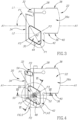
Fig. 1 is a perspective view of a cutting tool holder in accordance with some embodiments of the present invention; -
Fig. 2 is a partially exploded perspective view of the cutting tool holder shown inFig. 1 ; -
Fig. 3 is a side view of a holder body in accordance with some embodiments of the present invention; -
Fig. 4 is a side view of the cutting tool holder shown inFig. 1 ; -
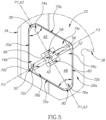
Fig. 5 is a detailed view of the cutting tool holder shown inFig. 4 ; -
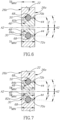
Fig. 6 is a cross-sectional view of the cutting tool holder shown inFig. 4 , taken along the line VI-VI; and -
Fig. 7 is a cross-sectional view of the cutting tool holder shown inFig. 4 , taken along the line VII-VII. - In one embodiment, the present invention relates to a
cutting tool holder 20 comprising aholder body 22 with a generally elongated shape and a longitudinal axis A1, and aweight aperture 30. Aweight assembly 24 may be retained in theweight aperture 30. - As shown in
Figs. 1 and 2 , theholder body 22 has opposing first andsecond side surfaces top surface 28 extending therebetween, and with theweight aperture 30 opening out to the first andsecond side surfaces weight assembly 24 is located within theweight aperture 30. - In some embodiments of the present invention, as shown in
Fig. 3 , in a side view of theholder body 22, theweight aperture 30 may have a non-circular shape. - Also in some embodiments of the present invention, as shown in
Fig. 3 , in a side view of theholder body 22, theweight aperture 30 may have a generally parallelogrammatic shape. - As shown in
Figs. 1 to 4 , aninsert mounting portion 32 is located at afront end 34 of theholder body 22 adjacent to thetop surface 28. - In some embodiments of the present invention, the
holder body 22 may include abottom surface 36 extending between the first andsecond side surfaces top surface 28. - As shown in
Figs. 3 and 4 , the top andbottom surfaces lower abutment surfaces cutting tool holder 20 into an elongated tool block (not shown) having parallel extending retaining grooves. - As shown in
Figs. 2 and3 , theweight aperture 30 may be located adjacent to thefront end 34 of theholder body 22. - In some embodiments of the present invention, the
weight aperture 30 may be at least partially located in abottom protuberance 42 extending downwardly from thelower abutment surface 40. - As shown in
Fig. 3 , in a side view of theholder body 22, the upper andlower abutment surfaces weight aperture 30. - The provision of the
bottom protuberance 42 enables theweight aperture 30 and theinsert mounting portion 32 to be sufficiently spaced apart, so that theelongated holder body 22 retains an adequately high level of stiffness. - As shown in
Figs. 2 and3 , theweight aperture 30 has an apertureinner surface 44, and an aperture axis A2 extending transversely to the longitudinal axis A1. - In some embodiments of the present invention, as shown in
Fig. 3 , theweight aperture 30 may exhibit mirror symmetry about a first plane P1 containing the aperture axis A2. - As shown in
Fig. 3 , in a side view of theholder body 22, the aperture axis A2 may be located below the second imaginary line L2. - In some embodiments of the present invention, as shown in
Fig. 3 , the first plane P1 may form an acute aperture angle α with the longitudinal axis A1 and not intersect thetop surface 28. - Also in some embodiments of the present invention, the aperture angle α may have a value of greater than 25° and less than 65°.
- According to one embodiment of the present invention, as shown in
Figs. 1, 2 and4 , theweight assembly 24 comprises: - a
first weight portion 46; - a
second weight portion 48; - a
damping ring 50 located along the apertureinner surface 44; and - an actuating
member 52 interfacing and urging the first andsecond weight portions inner surface 44, such that eachweight portion damping ring 50 within theweight aperture 30. - In some embodiments of the present invention, the first and
second weight portions holder body 22. - For example, if the
holder body 22 is formed of steel, the first andsecond weight portions - Also in some embodiments of the present invention, the
damping ring 50 may be formed of an elastic compressible material, such as rubber. - As shown in
Figs. 1, 2 and4 , acutting insert 54 is retained in theinsert mounting portion 32 of theholder body 22, for performing cutting operations on a workpiece, e.g., turning, grooving or parting. - During such cutting operations with long overhangs, the
holder body 22 may be prone to vibrations and chatter, which disturbs the engagement of thecutting insert 54 with the workpiece, and which may damage the cutting operation or the surface quality of the workpiece. - In order to reduce or eliminate such unwanted vibrations and chatter, the
weight assembly 24 acts as a Dynamic Vibration Absorber (DVA) or a Tuned Mass Damper (TMD) for theholder body 22, by increasing the weight of itsfront end 34, wherein thedamping ring 50 acts as a spring and theweight portions weight assembly 24 may thus be referred to as a vibrationdamping weight assembly 24. Vibrations of theholder body 22 are transferred through thedamping ring 50 to theweight portions holder body 22. - As shown in
Figs. 4 and5 , each of the first andsecond weight portions second weight portions - As shown in
Fig. 2 , thedamping ring 50 may be an O-ring, suitable for location along the apertureinner surface 44 of the non-circular shapedweight aperture 30. - As shown in
Fig. 4 , a second plane P2 perpendicular to the longitudinal axis A1 may intersect thecutting insert 54 and at least one of the first andsecond weight portions - In some embodiments of the present invention, the second plane P2 may intersect the
cutting insert 54 and both of the first andsecond weight portions - Locating the
weight assembly 24 adjacent to thefront end 34 of theholder body 22 such that the second plane P2 intersects at least one of the first andsecond weight portions front end 34 which thus improves the damping performance of theweight assembly 24. - In some embodiments of the present invention, the actuating
member 52 may be rotatable about an actuating axis A3 contained in the first plane P1. - As shown in
Figs. 4 and5 , the actuating axis A3 may be perpendicular to aperture axis A2. - In some embodiments of the present invention, the actuating
member 52 may comprise acentral portion 56 located between two cylindrical-shaped end portions - As shown in
Fig. 2 , a first of the twoend portions 58 may engage afirst bore 62 in thefirst weight portion 46, and a second of the twoend portions 60 may engage asecond bore 64 in thesecond weight portion 48. - In some embodiments of the present invention, the actuating axis A3 may be coaxial with the first and
second bores - Also in some embodiments of the present invention, at least one of the first and
second end portions second bores - Further in some embodiments of the present invention, the two
end portions second end portions second bores - Yet further in some embodiments of the present invention, the
central portion 56 may include asocket 66, or other means of rotation. - When the actuating
member 52 is rotated in a first direction D1 about the actuating axis A3, the first andsecond weight portions ring 50 is elastically compressed against the apertureinner surface 44. - In this tightened position, the first and
second weight portions weight aperture 30, and apart from interfacing with the actuatingmember 52, the first andsecond weight portions ring 50. - As shown in
Figs. 4 and5 , the first andsecond weight portions inner surface 44. - In this manner, the damping
ring 50 is restrained between the first andsecond weight portions inner surface 44. Thus, theentire weight assembly 24 is restrained within theweight aperture 30, prevented from falling out therefrom. - When the actuating
member 52 is rotated in a second direction D2 about the actuating axis A3, opposite to the first direction D1, the first andsecond weight portions ring 50 is reduced. - The amount to which the actuating
member 52 is rotated in the first or second directions D1, D2 about the actuating axis A3 affects the amount to which the dampingring 50 is elastically compressed against the apertureinner surface 44. This also affects the extent of contact between the first andsecond weight portions ring 50, and between the dampingring 50 and the apertureinner surface 44. In the DVA aspect of theweight assembly 24, this fine tuning determines the spring constant of the dampingring 50. - Continued rotation of the actuating
member 52 in the second direction D2 about the actuating axis A3, reduces the distance between the first andsecond weight portions ring 50, and the first andsecond weight portions member 52 may be easily removed from theweight aperture 30, and replaced by other weight portions, as required. This flexibility is an advantage over other vibration damping weights which are fixedly coupled to the holder body, for example, by soldering or brazing, with no option of disassembly or replacement of the weights. - As shown in
Fig. 3 , theweight aperture 30 may exhibit mirror symmetry about a third plane P3 containing the aperture axis A2 and perpendicular to the first plane P1. - As shown in
Figs. 4 and5 , the first andsecond weight portions - In some embodiments of the present invention, an
inner groove 68 may continuously extend along the apertureinner surface 44, and the dampingring 50 may interface with theinner groove 68. - As shown in
Figs. 6 and 7 , theinner groove 68 may be V-shaped when viewed in a cross-section containing the aperture axis A2. - Also as shown in
Figs. 6 and 7 , the apertureinner surface 44 may be inclined at a first slope angle β1 with respect to the aperture axis A2, to aid removal and replacement of theweight assembly 24. - In some embodiments of the present invention, the first slope angle β1 may have a value of less than 15°.
- As shown in
Fig. 5 , in a side view of thecutting tool holder 20, both of the first andsecond weight portions peripheral surfaces corners - Also as shown in
Fig. 5 , first and secondperipheral surfaces first corners second weight portions first corners - In some embodiments of the present invention, each of the
first corners peripheral surface peripheral surfaces - The weight of the
weight assembly 24, and in particular the weight of each of the first andsecond weight portions second weight portions holder body 22, and according to the cutting operations to be performed with thecutting tool holder 20. The characteristics of theweight assembly 24 may change in different cutting tool holders. Alternatively, thecutting tool holder 20 may be used withdifferent weight assemblies 24. - In some embodiments of the present invention, first and second
outer grooves peripheral surfaces second weight portions ring 50 may interface with each of the first and secondouter grooves - As shown in
Figs. 6 and 7 , each of the first and secondouter grooves - Also as shown in
Figs. 6 and 7 , each of the first and secondperipheral surfaces - In some embodiments of the present invention, the second slope angle β2 may be equal to the first slope angle β1.
- Further as shown in
Figs. 6 and 7 , each of the first andsecond weight portions holder body 22 at theweight aperture 30, so that theweight assembly 24 does not protrude beyond the first andsecond side surfaces - In some embodiments of the present invention, the
holder body 22 may be blade-shaped, having a maximum body thickness TBMAX between the first andsecond side surfaces holder body 22 at theweight aperture 30. - While the present invention has been described with reference to one or more specific embodiments, the description is intended to be illustrative as a whole and is not to be construed as limiting the invention to the embodiments shown. It is appreciated that various modifications may occur to those skilled in the art that, while not specifically shown herein, are nevertheless within the scope of the claims.
Claims (15)
- A cutting tool holder (20), comprising:a holder body (22) having a longitudinal axis (A1), and comprising:opposing first and second side surfaces (26a, 26b) and a top surface (28) extending therebetween;an insert mounting portion (32) located at a front end (34) of the holder body (22) adjacent to the top surface (28);a weight aperture (30) comprising an aperture inner surface (44), and an aperture axis (A2) extending transversely to the longitudinal axis (A1);
anda weight assembly (24) located within the weight aperture (30), characterized by the weight assembly (24) further comprising:a first weight portion (46);a second weight portion (48);a damping ring (50) located along the aperture inner surface (44); andan actuating member (52) interfacing and urging the first and second weight portions (46, 48) away from one another, such that each weight portion (46, 48) presses against the damping ring (50) within the weight aperture (30), and with the weight aperture (30) opening out to the first and second side surfaces (26a, 26b). - The cutting tool holder (20) according to claim 1, wherein in a side view of the holder body (22), the weight aperture (30) has a non-circular shape.
- The cutting tool holder (20) according to claim 1 or 2, wherein:each of the first and second weight portions (46, 48) has a maximum weight thickness (TWMAX) in the direction of the aperture axis (A2); andthe maximum weight thickness (TWMAX) is less than or equal to the minimum thickness (TAMIN) of the holder body (22) at the weight aperture (30).
- The cutting tool holder (20) according to any one of the preceding claims, wherein:the actuating member (52) comprises a central portion (56) located between two cylindrical-shaped end portions (58, 60);a first of the two end portions (58) engages a first bore (62) in the first weight portion (46), and a second of the two end portions (60) engages a second bore (64) in the second weight portion (48); andat least one of the first and second end portions (58, 60) threadingly engages the respective first and second bores (62, 64).
- The cutting tool holder (20) according to any one of the preceding claims, wherein the weight aperture (30) is located adjacent to the front end (34) of the holder body (22).
- The cutting tool holder (20) according to any one of the preceding claims, wherein the first and second weight portions (46, 48) are formed of a material denser than the material of the holder body (22).
- The cutting tool holder (20) according to any one of the preceding claims, wherein an inner groove (68) continuously extends along the aperture inner surface (44), and the damping ring (50) interfaces with the inner groove (68).
- The cutting tool holder (20) according to any one of the preceding claims, wherein:the holder body (22) includes a bottom surface (36) extending between the first and second side surfaces (26a, 26b) opposite the top surface (28); andthe top and bottom surfaces (28, 36) include upper and lower abutment surfaces (38, 40), respectively, extending parallel to the longitudinal axis (A1).
- The cutting tool holder (20) according to claim 8, wherein in a side view of the holder body (22):the upper and lower abutment surfaces (38, 40) define parallel first and second imaginary straight lines (L1, L2), respectively; andthe second imaginary straight line (L2) intersects the weight aperture (30).
- The cutting tool holder (20) according to any one of the preceding claims, wherein the weight aperture (30) exhibits mirror symmetry about a first plane (P1) containing the aperture axis (A2).
- The cutting tool holder (20) according to claim 10, wherein in a side view of the cutting tool holder (20), both of the first and second weight portions (46, 48) have a triangular shape, defined by three peripheral surfaces (70a, 70b, 70c; 72a, 72b, 72c) extending between three corners (74a, 74b, 74c; 76a, 76b, 76c).
- The cutting tool holder (20) according to claim 11, wherein:first and second peripheral surfaces (70a, 70b; 72a, 72b) diverging away from respective first corners (74a, 76a) of the first and second weight portions (46, 48) form acute first corner angles (γ), andthe first plane (P1) bisects each of the first corners (74a, 76a).
- The cutting tool holder (20) according to claim 11 or 12, wherein:first and second outer grooves (82a, 82b; 84a, 84b) extend along the first and second peripheral surfaces (70a, 70b; 72a, 72b), respectively, of both of the first and second weight portions (46, 48); andthe damping ring (50) interfaces with each of the first and second outer grooves (82a, 82b; 84a, 84b).
- The cutting tool holder (20) according to any one of claims 10 to 13, wherein the actuating member (52) is rotatable about an actuating axis (A3) contained in the first plane (P1).
- The cutting tool holder (20) according to any one of claims 10 to 14, wherein the weight aperture (30) exhibits mirror symmetry about a third plane (P3) containing the aperture axis (A2) and perpendicular to the first plane (P1) and wherein the first and second weight portions (46, 48) are entirely located on opposite sides of the third plane (P3).
Priority Applications (1)
| Application Number | Priority Date | Filing Date | Title |
|---|---|---|---|
| EP19162821.3A EP3533543B1 (en) | 2015-12-21 | 2016-12-12 | CUTTING TOOL HOLDER WITH VIBRATION-DAMPING WEIGHT ARRANGEMENT |
Applications Claiming Priority (2)
| Application Number | Priority Date | Filing Date | Title |
|---|---|---|---|
| US14/976,442 US9993876B2 (en) | 2015-12-21 | 2015-12-21 | Cutting tool holder with vibration damping weight assembly |
| PCT/IL2016/051326 WO2017109771A2 (en) | 2015-12-21 | 2016-12-12 | Cutting tool holder with vibration damping weight assembly |
Related Child Applications (2)
| Application Number | Title | Priority Date | Filing Date |
|---|---|---|---|
| EP19162821.3A Division-Into EP3533543B1 (en) | 2015-12-21 | 2016-12-12 | CUTTING TOOL HOLDER WITH VIBRATION-DAMPING WEIGHT ARRANGEMENT |
| EP19162821.3A Division EP3533543B1 (en) | 2015-12-21 | 2016-12-12 | CUTTING TOOL HOLDER WITH VIBRATION-DAMPING WEIGHT ARRANGEMENT |
Publications (3)
| Publication Number | Publication Date |
|---|---|
| EP3393704A2 EP3393704A2 (en) | 2018-10-31 |
| EP3393704C0 EP3393704C0 (en) | 2023-07-12 |
| EP3393704B1 true EP3393704B1 (en) | 2023-07-12 |
Family
ID=57708632
Family Applications (2)
| Application Number | Title | Priority Date | Filing Date |
|---|---|---|---|
| EP16820364.4A Active EP3393704B1 (en) | 2015-12-21 | 2016-12-12 | Cutting tool holder with vibration-damping weight assembly |
| EP19162821.3A Active EP3533543B1 (en) | 2015-12-21 | 2016-12-12 | CUTTING TOOL HOLDER WITH VIBRATION-DAMPING WEIGHT ARRANGEMENT |
Family Applications After (1)
| Application Number | Title | Priority Date | Filing Date |
|---|---|---|---|
| EP19162821.3A Active EP3533543B1 (en) | 2015-12-21 | 2016-12-12 | CUTTING TOOL HOLDER WITH VIBRATION-DAMPING WEIGHT ARRANGEMENT |
Country Status (13)
| Country | Link |
|---|---|
| US (1) | US9993876B2 (en) |
| EP (2) | EP3393704B1 (en) |
| JP (1) | JP6961311B2 (en) |
| KR (1) | KR102503381B1 (en) |
| CN (1) | CN108367365B (en) |
| BR (1) | BR112018012659B1 (en) |
| CA (1) | CA3008582C (en) |
| ES (1) | ES2951172T3 (en) |
| IL (1) | IL259389B (en) |
| PL (1) | PL3393704T3 (en) |
| RU (1) | RU2717430C2 (en) |
| TW (1) | TWI709450B (en) |
| WO (1) | WO2017109771A2 (en) |
Families Citing this family (18)
| Publication number | Priority date | Publication date | Assignee | Title |
|---|---|---|---|---|
| DE102015002483B4 (en) * | 2015-02-27 | 2024-10-31 | Rattunde Ag | Method and device for reducing the regenerative chatter of cutting machines |
| EP3222376B1 (en) * | 2016-03-24 | 2019-01-23 | Seco Tools AB | Grooving blade, grooving tool and method of grooving a metallic workpiece |
| JP6059839B1 (en) * | 2016-04-04 | 2017-01-11 | 三菱日立パワーシステムズ株式会社 | Cutting tool and annular groove machining method |
| RU178436U1 (en) * | 2017-12-05 | 2018-04-04 | Акционерное общество "Научно-исследовательский инженерный институт" (АО "НИИИ") | CUTTER WITH DAMPING DEVICE |
| US10953471B2 (en) * | 2018-04-16 | 2021-03-23 | Iscar, Ltd. | External turning tool having a cutting portion with a transverse elongated damping mechanism |
| US10500648B1 (en) * | 2018-06-12 | 2019-12-10 | Iscar, Ltd. | Tool holder having integrally formed anti-vibration component and cutting tool provided with tool holder |
| CN109275429A (en) * | 2018-10-24 | 2019-01-29 | 南京申发冶金机械制造有限公司 | A kind of baler wear resistant cutters |
| CN109482917A (en) * | 2018-11-19 | 2019-03-19 | 重庆工业职业技术学院 | A kind of shockproof lathe tool |
| EP3760350B1 (en) | 2019-07-01 | 2023-12-20 | AB Sandvik Coromant | Metal cutting tool comprising a vibration damping member |
| CN112238227B (en) | 2019-07-17 | 2024-07-30 | 肯纳金属公司 | Cutting tool holder with improved damping effect |
| TWI718023B (en) * | 2020-03-06 | 2021-02-01 | 世邦興業股份有限公司 | Shock absorption damping structure of tool holder |
| CN111644644A (en) * | 2020-05-18 | 2020-09-11 | 成都戴梦迪超硬工具有限责任公司 | Toothed structure cutter capable of being rapidly clamped and repeatedly polished |
| RU199307U1 (en) * | 2020-05-21 | 2020-08-26 | Акционерное общество "Научно-исследовательский инженерный институт" (АО "НИИИ") | CUTTER WITH DAMPING DEVICE |
| EP4201563A4 (en) * | 2020-08-18 | 2024-03-20 | Sumitomo Electric Hardmetal Corp. | CUTTING TOOL AND CUTTING PROCESSING DEVICE |
| WO2022084988A2 (en) | 2020-10-20 | 2022-04-28 | Iscar Ltd. | Coolant conduit for a parting-off tool assembly |
| US12103091B2 (en) | 2021-01-21 | 2024-10-01 | Iscar, Ltd. | Tool holder having anti-vibration arrangement and cutting tool provided with tool holder |
| US11819925B2 (en) | 2021-09-30 | 2023-11-21 | Kennametal Inc. | Damper system for cutting tool |
| CN116690251B (en) * | 2023-08-05 | 2023-10-03 | 南京普莱机电有限公司 | Clamp for clamping workpiece |
Family Cites Families (47)
| Publication number | Priority date | Publication date | Assignee | Title |
|---|---|---|---|---|
| US3242791A (en) * | 1962-08-23 | 1966-03-29 | Richards & Co Ltd George | Vibration absorbing device for machine tools |
| US3774730A (en) * | 1972-04-19 | 1973-11-27 | Nl Industries Inc | Tool holder |
| GB1578342A (en) * | 1976-02-05 | 1980-11-05 | Nat Res Dev | Boring bars |
| SU726147A1 (en) * | 1977-04-05 | 1980-04-05 | Предприятие П/Я В-2438 | Method of preparing magnite varnish for information record carriers |
| SU1142260A1 (en) * | 1982-12-01 | 1985-02-28 | Предприятие П/Я В-8457 | Device for controlling accuracy of machining on metal-cutting machine |
| JPS61257702A (en) * | 1985-05-10 | 1986-11-15 | Kobe Steel Ltd | Long canti lever cutting tool |
| US5074723A (en) * | 1989-04-13 | 1991-12-24 | Kennametal Inc. | Method and apparatus for balancing a rotary tool assembly |
| SU1739133A1 (en) * | 1989-06-05 | 1992-06-07 | Ленинградский научно-исследовательский радиотехнический институт | Vibration isolator |
| IL91574A (en) * | 1989-09-08 | 1992-02-16 | Iscar Ltd | Cutting tool system having an exchangeable adaptor |
| RU2005000C1 (en) * | 1991-01-08 | 1993-12-30 | Научно-производственный кооператив "Ленинградска Аврора" | Universal sectional disk-type cutting tool |
| FR2727886A1 (en) * | 1994-12-12 | 1996-06-14 | Combustible Nucleaire Sicn Soc | TUBE SHAPING DEVICE |
| JPH08215904A (en) * | 1995-02-10 | 1996-08-27 | Sumitomo Electric Ind Ltd | Parting tool |
| SE511717C2 (en) | 1997-05-22 | 1999-11-15 | Sandvik Ab | Holder for turning operations |
| US6186704B1 (en) * | 1999-03-04 | 2001-02-13 | Kennametal Inc. | Toolholder with detachable blade |
| SE522081C2 (en) * | 2000-12-06 | 2004-01-13 | Sandvik Ab | Tools for machining in metallic materials |
| JP2003062703A (en) * | 2001-08-21 | 2003-03-05 | Mitsubishi Materials Corp | Damping tool |
| JP2003062704A (en) * | 2001-08-27 | 2003-03-05 | Mitsubishi Materials Corp | Damping tool |
| US6619165B2 (en) | 2002-02-01 | 2003-09-16 | Kennametal Inc. | Tunable toolholder |
| DE10239422A1 (en) * | 2002-08-28 | 2004-03-18 | Hartmetall-Werkzeugfabrik Paul Horn Gmbh | Machining tool |
| JP4011475B2 (en) * | 2002-12-26 | 2007-11-21 | 住友電工ハードメタル株式会社 | Cutting tools |
| SE528247C2 (en) * | 2004-05-07 | 2006-10-03 | Mircona Ab | Vibration dampened tool holder |
| US7987954B2 (en) * | 2004-06-18 | 2011-08-02 | Mcpherson Matthew A | Harmonic damper |
| DE102004050967A1 (en) * | 2004-10-15 | 2006-04-20 | Hainbuch Gmbh Spannende Technik | Clamping device and method for producing a clamping device |
| US7234379B2 (en) * | 2005-06-28 | 2007-06-26 | Ingvar Claesson | Device and a method for preventing or reducing vibrations in a cutting tool |
| JP4867661B2 (en) * | 2006-03-02 | 2012-02-01 | 三菱マテリアル株式会社 | Insert detachable cutting tool |
| US7393166B2 (en) * | 2006-08-07 | 2008-07-01 | Chin-Chiu Chen | Chuck in a processing machine |
| CN200945528Y (en) * | 2006-09-18 | 2007-09-12 | 黄宪仁 | Turning Tool Holder Structure |
| TWM308807U (en) * | 2006-10-16 | 2007-04-01 | Ruei-Min Liu | Improved tool structure |
| KR20100017111A (en) * | 2007-04-18 | 2010-02-16 | 해롤드 디. 쿠크 | Tool holder dampening system |
| RU89998U1 (en) * | 2009-02-02 | 2009-12-27 | Валерий Николаевич Филиппов | UNIVERSAL MULTI-FUNCTIONAL COMBINED CUTTER FOR TURNING MACHINE OF VALERY FILIPPOV SYSTEM |
| JP5433346B2 (en) * | 2009-08-21 | 2014-03-05 | 新日本工機株式会社 | Turning tool stay and turbine rotor machining lathe |
| IL202027A (en) * | 2009-11-10 | 2015-03-31 | Iscar Ltd | Cutting tool assembly |
| US8371776B2 (en) * | 2009-11-17 | 2013-02-12 | Ying-Fan Enterprise Co., Ltd. | Damper for a cutting tool |
| JP5613958B2 (en) * | 2010-09-10 | 2014-10-29 | 大昭和精機株式会社 | Vibration control mechanism |
| US8734070B2 (en) * | 2010-10-20 | 2014-05-27 | Kennametal Inc. | Toolholder with externally-mounted dynamic absorber |
| KR101258519B1 (en) | 2010-12-20 | 2013-04-29 | 두산중공업 주식회사 | Apparatus for damping vibration of tool carriage in lathe |
| JP5805019B2 (en) * | 2012-06-29 | 2015-11-04 | 独立行政法人国立高等専門学校機構 | Cutting tool gripper |
| DE102012108098A1 (en) * | 2012-08-31 | 2014-03-06 | Sandvik Intellectual Property Ab | Vibration-damped tool |
| CN202779863U (en) * | 2012-09-10 | 2013-03-13 | 台州威龙数控刀刃具制造有限公司 | Wheel hub lathe tool |
| CN203265662U (en) * | 2013-05-28 | 2013-11-06 | 谢中标 | Inner bore turning tool |
| US9168594B2 (en) * | 2013-08-23 | 2015-10-27 | Kennametal Inc | Toolholder with externally mounted tunable absorber mass |
| JP6324233B2 (en) * | 2014-06-25 | 2018-05-16 | Big Daishowa株式会社 | Anti-vibration structure of rotating body |
| US9533357B2 (en) * | 2014-06-30 | 2017-01-03 | Kennametal Inc | Optimized vibration absorber |
| CN203992435U (en) * | 2014-07-04 | 2014-12-10 | 皇顺企业股份有限公司 | ultrasonic main shaft structure |
| CN203917987U (en) * | 2014-07-07 | 2014-11-05 | 深圳市派高模业有限公司 | A kind of lengthened tool arbor for machine tooling |
| US9616502B2 (en) * | 2014-08-12 | 2017-04-11 | Iscar, Ltd. | Cutting tool holder with vibration damping weight assembly |
| US20160311031A1 (en) * | 2015-04-23 | 2016-10-27 | Enrico R. Giannetti | Through coolant machine tool having anti-vibration system |
-
2015
- 2015-12-21 US US14/976,442 patent/US9993876B2/en active Active
-
2016
- 2016-12-12 EP EP16820364.4A patent/EP3393704B1/en active Active
- 2016-12-12 BR BR112018012659-4A patent/BR112018012659B1/en active IP Right Grant
- 2016-12-12 JP JP2018523410A patent/JP6961311B2/en active Active
- 2016-12-12 WO PCT/IL2016/051326 patent/WO2017109771A2/en not_active Ceased
- 2016-12-12 CN CN201680074768.0A patent/CN108367365B/en active Active
- 2016-12-12 KR KR1020187017171A patent/KR102503381B1/en active Active
- 2016-12-12 EP EP19162821.3A patent/EP3533543B1/en active Active
- 2016-12-12 ES ES16820364T patent/ES2951172T3/en active Active
- 2016-12-12 CA CA3008582A patent/CA3008582C/en active Active
- 2016-12-12 RU RU2018126637A patent/RU2717430C2/en active
- 2016-12-12 PL PL16820364.4T patent/PL3393704T3/en unknown
- 2016-12-20 TW TW105142173A patent/TWI709450B/en active
-
2018
- 2018-05-15 IL IL259389A patent/IL259389B/en unknown
Also Published As
| Publication number | Publication date |
|---|---|
| TWI709450B (en) | 2020-11-11 |
| CA3008582A1 (en) | 2017-06-29 |
| KR102503381B1 (en) | 2023-02-28 |
| RU2018126637A (en) | 2020-01-23 |
| CA3008582C (en) | 2024-05-28 |
| RU2717430C2 (en) | 2020-03-23 |
| EP3393704C0 (en) | 2023-07-12 |
| IL259389A (en) | 2018-07-31 |
| CN108367365B (en) | 2020-12-18 |
| IL259389B (en) | 2021-08-31 |
| JP2018537297A (en) | 2018-12-20 |
| US20170173701A1 (en) | 2017-06-22 |
| BR112018012659B1 (en) | 2023-03-28 |
| KR20180095532A (en) | 2018-08-27 |
| TW201729926A (en) | 2017-09-01 |
| EP3533543B1 (en) | 2026-05-20 |
| EP3393704A2 (en) | 2018-10-31 |
| US9993876B2 (en) | 2018-06-12 |
| RU2018126637A3 (en) | 2020-02-18 |
| CN108367365A (en) | 2018-08-03 |
| EP3533543A1 (en) | 2019-09-04 |
| WO2017109771A2 (en) | 2017-06-29 |
| JP6961311B2 (en) | 2021-11-05 |
| BR112018012659A2 (en) | 2018-12-04 |
| WO2017109771A3 (en) | 2017-10-05 |
| ES2951172T3 (en) | 2023-10-18 |
| PL3393704T3 (en) | 2024-01-03 |
Similar Documents
| Publication | Publication Date | Title |
|---|---|---|
| CA3008582C (en) | Cutting tool holder with vibration damping weight assembly | |
| EP3194099B1 (en) | Cutting tool holder with vibration damping weight assembly | |
| US11000903B2 (en) | Blade, tool and method of grooving a metallic workpiece | |
| KR102076027B1 (en) | Slitting tool configured for fine-tuning | |
| EP3781340B1 (en) | External turning tool having a cutting portion with a transverse elongated damping mechanism |
Legal Events
| Date | Code | Title | Description |
|---|---|---|---|
| STAA | Information on the status of an ep patent application or granted ep patent |
Free format text: STATUS: UNKNOWN |
|
| STAA | Information on the status of an ep patent application or granted ep patent |
Free format text: STATUS: THE INTERNATIONAL PUBLICATION HAS BEEN MADE |
|
| PUAI | Public reference made under article 153(3) epc to a published international application that has entered the european phase |
Free format text: ORIGINAL CODE: 0009012 |
|
| STAA | Information on the status of an ep patent application or granted ep patent |
Free format text: STATUS: REQUEST FOR EXAMINATION WAS MADE |
|
| 17P | Request for examination filed |
Effective date: 20180619 |
|
| AK | Designated contracting states |
Kind code of ref document: A2 Designated state(s): AL AT BE BG CH CY CZ DE DK EE ES FI FR GB GR HR HU IE IS IT LI LT LU LV MC MK MT NL NO PL PT RO RS SE SI SK SM TR |
|
| AX | Request for extension of the european patent |
Extension state: BA ME |
|
| DAV | Request for validation of the european patent (deleted) | ||
| DAX | Request for extension of the european patent (deleted) | ||
| GRAP | Despatch of communication of intention to grant a patent |
Free format text: ORIGINAL CODE: EPIDOSNIGR1 |
|
| STAA | Information on the status of an ep patent application or granted ep patent |
Free format text: STATUS: GRANT OF PATENT IS INTENDED |
|
| INTG | Intention to grant announced |
Effective date: 20220608 |
|
| GRAJ | Information related to disapproval of communication of intention to grant by the applicant or resumption of examination proceedings by the epo deleted |
Free format text: ORIGINAL CODE: EPIDOSDIGR1 |
|
| STAA | Information on the status of an ep patent application or granted ep patent |
Free format text: STATUS: REQUEST FOR EXAMINATION WAS MADE |
|
| INTC | Intention to grant announced (deleted) | ||
| GRAP | Despatch of communication of intention to grant a patent |
Free format text: ORIGINAL CODE: EPIDOSNIGR1 |
|
| STAA | Information on the status of an ep patent application or granted ep patent |
Free format text: STATUS: GRANT OF PATENT IS INTENDED |
|
| INTG | Intention to grant announced |
Effective date: 20230118 |
|
| GRAS | Grant fee paid |
Free format text: ORIGINAL CODE: EPIDOSNIGR3 |
|
| GRAA | (expected) grant |
Free format text: ORIGINAL CODE: 0009210 |
|
| STAA | Information on the status of an ep patent application or granted ep patent |
Free format text: STATUS: THE PATENT HAS BEEN GRANTED |
|
| AK | Designated contracting states |
Kind code of ref document: B1 Designated state(s): AL AT BE BG CH CY CZ DE DK EE ES FI FR GB GR HR HU IE IS IT LI LT LU LV MC MK MT NL NO PL PT RO RS SE SI SK SM TR |
|
| REG | Reference to a national code |
Ref country code: CH Ref legal event code: EP |
|
| REG | Reference to a national code |
Ref country code: DE Ref legal event code: R096 Ref document number: 602016081021 Country of ref document: DE |
|
| REG | Reference to a national code |
Ref country code: IE Ref legal event code: FG4D |
|
| U01 | Request for unitary effect filed |
Effective date: 20230801 |
|
| U07 | Unitary effect registered |
Designated state(s): AT BE BG DE DK EE FI FR IT LT LU LV MT NL PT SE SI Effective date: 20230901 |
|
| REG | Reference to a national code |
Ref country code: ES Ref legal event code: FG2A Ref document number: 2951172 Country of ref document: ES Kind code of ref document: T3 Effective date: 20231018 |
|
| REG | Reference to a national code |
Ref country code: LT Ref legal event code: MG9D |
|
| U20 | Renewal fee for the european patent with unitary effect paid |
Year of fee payment: 8 Effective date: 20231106 |
|
| PG25 | Lapsed in a contracting state [announced via postgrant information from national office to epo] |
Ref country code: GR Free format text: LAPSE BECAUSE OF FAILURE TO SUBMIT A TRANSLATION OF THE DESCRIPTION OR TO PAY THE FEE WITHIN THE PRESCRIBED TIME-LIMIT Effective date: 20231013 |
|
| PG25 | Lapsed in a contracting state [announced via postgrant information from national office to epo] |
Ref country code: IS Free format text: LAPSE BECAUSE OF FAILURE TO SUBMIT A TRANSLATION OF THE DESCRIPTION OR TO PAY THE FEE WITHIN THE PRESCRIBED TIME-LIMIT Effective date: 20231112 |
|
| PG25 | Lapsed in a contracting state [announced via postgrant information from national office to epo] |
Ref country code: RS Free format text: LAPSE BECAUSE OF FAILURE TO SUBMIT A TRANSLATION OF THE DESCRIPTION OR TO PAY THE FEE WITHIN THE PRESCRIBED TIME-LIMIT Effective date: 20230712 Ref country code: NO Free format text: LAPSE BECAUSE OF FAILURE TO SUBMIT A TRANSLATION OF THE DESCRIPTION OR TO PAY THE FEE WITHIN THE PRESCRIBED TIME-LIMIT Effective date: 20231012 Ref country code: IS Free format text: LAPSE BECAUSE OF FAILURE TO SUBMIT A TRANSLATION OF THE DESCRIPTION OR TO PAY THE FEE WITHIN THE PRESCRIBED TIME-LIMIT Effective date: 20231112 Ref country code: HR Free format text: LAPSE BECAUSE OF FAILURE TO SUBMIT A TRANSLATION OF THE DESCRIPTION OR TO PAY THE FEE WITHIN THE PRESCRIBED TIME-LIMIT Effective date: 20230712 Ref country code: GR Free format text: LAPSE BECAUSE OF FAILURE TO SUBMIT A TRANSLATION OF THE DESCRIPTION OR TO PAY THE FEE WITHIN THE PRESCRIBED TIME-LIMIT Effective date: 20231013 |
|
| REG | Reference to a national code |
Ref country code: DE Ref legal event code: R097 Ref document number: 602016081021 Country of ref document: DE |
|
| PG25 | Lapsed in a contracting state [announced via postgrant information from national office to epo] |
Ref country code: SM Free format text: LAPSE BECAUSE OF FAILURE TO SUBMIT A TRANSLATION OF THE DESCRIPTION OR TO PAY THE FEE WITHIN THE PRESCRIBED TIME-LIMIT Effective date: 20230712 Ref country code: RO Free format text: LAPSE BECAUSE OF FAILURE TO SUBMIT A TRANSLATION OF THE DESCRIPTION OR TO PAY THE FEE WITHIN THE PRESCRIBED TIME-LIMIT Effective date: 20230712 Ref country code: SK Free format text: LAPSE BECAUSE OF FAILURE TO SUBMIT A TRANSLATION OF THE DESCRIPTION OR TO PAY THE FEE WITHIN THE PRESCRIBED TIME-LIMIT Effective date: 20230712 |
|
| PLBE | No opposition filed within time limit |
Free format text: ORIGINAL CODE: 0009261 |
|
| STAA | Information on the status of an ep patent application or granted ep patent |
Free format text: STATUS: NO OPPOSITION FILED WITHIN TIME LIMIT |
|
| 26N | No opposition filed |
Effective date: 20240415 |
|
| REG | Reference to a national code |
Ref country code: CH Ref legal event code: PL |
|
| PG25 | Lapsed in a contracting state [announced via postgrant information from national office to epo] |
Ref country code: MC Free format text: LAPSE BECAUSE OF FAILURE TO SUBMIT A TRANSLATION OF THE DESCRIPTION OR TO PAY THE FEE WITHIN THE PRESCRIBED TIME-LIMIT Effective date: 20230712 |
|
| PG25 | Lapsed in a contracting state [announced via postgrant information from national office to epo] |
Ref country code: MC Free format text: LAPSE BECAUSE OF FAILURE TO SUBMIT A TRANSLATION OF THE DESCRIPTION OR TO PAY THE FEE WITHIN THE PRESCRIBED TIME-LIMIT Effective date: 20230712 |
|
| REG | Reference to a national code |
Ref country code: IE Ref legal event code: MM4A |
|
| PG25 | Lapsed in a contracting state [announced via postgrant information from national office to epo] |
Ref country code: IE Free format text: LAPSE BECAUSE OF NON-PAYMENT OF DUE FEES Effective date: 20231212 |
|
| PG25 | Lapsed in a contracting state [announced via postgrant information from national office to epo] |
Ref country code: CH Free format text: LAPSE BECAUSE OF NON-PAYMENT OF DUE FEES Effective date: 20231231 |
|
| PG25 | Lapsed in a contracting state [announced via postgrant information from national office to epo] |
Ref country code: IE Free format text: LAPSE BECAUSE OF NON-PAYMENT OF DUE FEES Effective date: 20231212 Ref country code: CH Free format text: LAPSE BECAUSE OF NON-PAYMENT OF DUE FEES Effective date: 20231231 |
|
| U20 | Renewal fee for the european patent with unitary effect paid |
Year of fee payment: 9 Effective date: 20241118 |
|
| PG25 | Lapsed in a contracting state [announced via postgrant information from national office to epo] |
Ref country code: CY Free format text: LAPSE BECAUSE OF FAILURE TO SUBMIT A TRANSLATION OF THE DESCRIPTION OR TO PAY THE FEE WITHIN THE PRESCRIBED TIME-LIMIT; INVALID AB INITIO Effective date: 20161212 |
|
| PG25 | Lapsed in a contracting state [announced via postgrant information from national office to epo] |
Ref country code: HU Free format text: LAPSE BECAUSE OF FAILURE TO SUBMIT A TRANSLATION OF THE DESCRIPTION OR TO PAY THE FEE WITHIN THE PRESCRIBED TIME-LIMIT; INVALID AB INITIO Effective date: 20161212 |
|
| U20 | Renewal fee for the european patent with unitary effect paid |
Year of fee payment: 10 Effective date: 20251118 |
|
| PGFP | Annual fee paid to national office [announced via postgrant information from national office to epo] |
Ref country code: GB Payment date: 20251114 Year of fee payment: 10 |
|
| PGFP | Annual fee paid to national office [announced via postgrant information from national office to epo] |
Ref country code: TR Payment date: 20251107 Year of fee payment: 10 |
|
| PGFP | Annual fee paid to national office [announced via postgrant information from national office to epo] |
Ref country code: CZ Payment date: 20251013 Year of fee payment: 10 |
|
| PGFP | Annual fee paid to national office [announced via postgrant information from national office to epo] |
Ref country code: PL Payment date: 20251017 Year of fee payment: 10 |
|
| PGFP | Annual fee paid to national office [announced via postgrant information from national office to epo] |
Ref country code: ES Payment date: 20260122 Year of fee payment: 10 |