EP3393663B1 - Method of partitioning an aqueous test sample - Google Patents
Method of partitioning an aqueous test sample Download PDFInfo
- Publication number
- EP3393663B1 EP3393663B1 EP16831789.9A EP16831789A EP3393663B1 EP 3393663 B1 EP3393663 B1 EP 3393663B1 EP 16831789 A EP16831789 A EP 16831789A EP 3393663 B1 EP3393663 B1 EP 3393663B1
- Authority
- EP
- European Patent Office
- Prior art keywords
- film
- wells
- polymer
- stems
- posts
- Prior art date
- Legal status (The legal status is an assumption and is not a legal conclusion. Google has not performed a legal analysis and makes no representation as to the accuracy of the status listed.)
- Active
Links
- 238000000034 method Methods 0.000 title claims description 33
- 238000000638 solvent extraction Methods 0.000 title claims description 24
- 239000010408 film Substances 0.000 claims description 147
- -1 polypropylene Polymers 0.000 claims description 26
- 239000000463 material Substances 0.000 claims description 25
- 229920000642 polymer Polymers 0.000 claims description 16
- 239000004743 Polypropylene Substances 0.000 claims description 7
- 229920000058 polyacrylate Polymers 0.000 claims description 7
- 229920001155 polypropylene Polymers 0.000 claims description 7
- 229920000728 polyester Polymers 0.000 claims description 6
- 239000012530 fluid Substances 0.000 claims description 5
- 229920002635 polyurethane Polymers 0.000 claims description 5
- 239000004814 polyurethane Substances 0.000 claims description 5
- 229920000915 polyvinyl chloride Polymers 0.000 claims description 5
- 239000004800 polyvinyl chloride Substances 0.000 claims description 5
- 239000004698 Polyethylene Substances 0.000 claims description 4
- 229920001577 copolymer Polymers 0.000 claims description 4
- 239000004205 dimethyl polysiloxane Substances 0.000 claims description 4
- 229920000435 poly(dimethylsiloxane) Polymers 0.000 claims description 4
- 229920000573 polyethylene Polymers 0.000 claims description 4
- 229920005573 silicon-containing polymer Polymers 0.000 claims description 4
- 239000004952 Polyamide Substances 0.000 claims description 3
- 229920002647 polyamide Polymers 0.000 claims description 3
- 229920006324 polyoxymethylene Polymers 0.000 claims description 3
- DHKHKXVYLBGOIT-UHFFFAOYSA-N 1,1-Diethoxyethane Chemical compound CCOC(C)OCC DHKHKXVYLBGOIT-UHFFFAOYSA-N 0.000 claims description 2
- WHNWPMSKXPGLAX-UHFFFAOYSA-N N-Vinyl-2-pyrrolidone Chemical compound C=CN1CCCC1=O WHNWPMSKXPGLAX-UHFFFAOYSA-N 0.000 claims description 2
- QYKIQEUNHZKYBP-UHFFFAOYSA-N Vinyl ether Chemical compound C=COC=C QYKIQEUNHZKYBP-UHFFFAOYSA-N 0.000 claims description 2
- 239000011354 acetal resin Substances 0.000 claims description 2
- DQXBYHZEEUGOBF-UHFFFAOYSA-N but-3-enoic acid;ethene Chemical compound C=C.OC(=O)CC=C DQXBYHZEEUGOBF-UHFFFAOYSA-N 0.000 claims description 2
- 239000013039 cover film Substances 0.000 claims description 2
- 150000004292 cyclic ethers Chemical class 0.000 claims description 2
- 239000003822 epoxy resin Substances 0.000 claims description 2
- 239000005038 ethylene vinyl acetate Substances 0.000 claims description 2
- 230000002209 hydrophobic effect Effects 0.000 claims description 2
- 150000002596 lactones Chemical class 0.000 claims description 2
- 229920001200 poly(ethylene-vinyl acetate) Polymers 0.000 claims description 2
- 229920000647 polyepoxide Polymers 0.000 claims description 2
- 229920000098 polyolefin Polymers 0.000 claims description 2
- 238000007152 ring opening metathesis polymerisation reaction Methods 0.000 claims description 2
- 229920002554 vinyl polymer Polymers 0.000 claims description 2
- 238000001035 drying Methods 0.000 claims 1
- 238000010030 laminating Methods 0.000 claims 1
- 239000000523 sample Substances 0.000 description 40
- 239000000203 mixture Substances 0.000 description 11
- 239000010410 layer Substances 0.000 description 9
- 238000000926 separation method Methods 0.000 description 8
- 239000007788 liquid Substances 0.000 description 7
- 229920005989 resin Polymers 0.000 description 7
- 239000011347 resin Substances 0.000 description 7
- 239000012488 sample solution Substances 0.000 description 7
- NIXOWILDQLNWCW-UHFFFAOYSA-M Acrylate Chemical compound [O-]C(=O)C=C NIXOWILDQLNWCW-UHFFFAOYSA-M 0.000 description 6
- 239000004820 Pressure-sensitive adhesive Substances 0.000 description 6
- 239000007864 aqueous solution Substances 0.000 description 5
- 238000000465 moulding Methods 0.000 description 5
- KWVGIHKZDCUPEU-UHFFFAOYSA-N 2,2-dimethoxy-2-phenylacetophenone Chemical compound C=1C=CC=CC=1C(OC)(OC)C(=O)C1=CC=CC=C1 KWVGIHKZDCUPEU-UHFFFAOYSA-N 0.000 description 4
- 229920002037 poly(vinyl butyral) polymer Polymers 0.000 description 4
- 229920001296 polysiloxane Polymers 0.000 description 4
- 239000012790 adhesive layer Substances 0.000 description 3
- 238000004049 embossing Methods 0.000 description 3
- 230000002093 peripheral effect Effects 0.000 description 3
- 230000005855 radiation Effects 0.000 description 3
- RBTBFTRPCNLSDE-UHFFFAOYSA-N 3,7-bis(dimethylamino)phenothiazin-5-ium Chemical compound C1=CC(N(C)C)=CC2=[S+]C3=CC(N(C)C)=CC=C3N=C21 RBTBFTRPCNLSDE-UHFFFAOYSA-N 0.000 description 2
- 239000000853 adhesive Substances 0.000 description 2
- 230000001070 adhesive effect Effects 0.000 description 2
- 238000006243 chemical reaction Methods 0.000 description 2
- 229960000907 methylthioninium chloride Drugs 0.000 description 2
- 239000000178 monomer Substances 0.000 description 2
- 238000005192 partition Methods 0.000 description 2
- PSGCQDPCAWOCSH-UHFFFAOYSA-N (4,7,7-trimethyl-3-bicyclo[2.2.1]heptanyl) prop-2-enoate Chemical compound C1CC2(C)C(OC(=O)C=C)CC1C2(C)C PSGCQDPCAWOCSH-UHFFFAOYSA-N 0.000 description 1
- VOBUAPTXJKMNCT-UHFFFAOYSA-N 1-prop-2-enoyloxyhexyl prop-2-enoate Chemical compound CCCCCC(OC(=O)C=C)OC(=O)C=C VOBUAPTXJKMNCT-UHFFFAOYSA-N 0.000 description 1
- GOXQRTZXKQZDDN-UHFFFAOYSA-N 2-Ethylhexyl acrylate Chemical compound CCCCC(CC)COC(=O)C=C GOXQRTZXKQZDDN-UHFFFAOYSA-N 0.000 description 1
- 229920004943 Delrin® Polymers 0.000 description 1
- 239000004593 Epoxy Substances 0.000 description 1
- JOYRKODLDBILNP-UHFFFAOYSA-N Ethyl urethane Chemical compound CCOC(N)=O JOYRKODLDBILNP-UHFFFAOYSA-N 0.000 description 1
- 229920002292 Nylon 6 Polymers 0.000 description 1
- 229920002302 Nylon 6,6 Polymers 0.000 description 1
- 229930182556 Polyacetal Natural products 0.000 description 1
- 229920002396 Polyurea Polymers 0.000 description 1
- 239000004433 Thermoplastic polyurethane Substances 0.000 description 1
- NIXOWILDQLNWCW-UHFFFAOYSA-N acrylic acid group Chemical group C(C=C)(=O)O NIXOWILDQLNWCW-UHFFFAOYSA-N 0.000 description 1
- 239000004676 acrylonitrile butadiene styrene Substances 0.000 description 1
- 239000002390 adhesive tape Substances 0.000 description 1
- 229920006378 biaxially oriented polypropylene Polymers 0.000 description 1
- 239000011127 biaxially oriented polypropylene Substances 0.000 description 1
- 230000015572 biosynthetic process Effects 0.000 description 1
- 239000001045 blue dye Substances 0.000 description 1
- 238000004891 communication Methods 0.000 description 1
- 238000010276 construction Methods 0.000 description 1
- 230000007423 decrease Effects 0.000 description 1
- 229920001971 elastomer Polymers 0.000 description 1
- 239000000806 elastomer Substances 0.000 description 1
- 238000001704 evaporation Methods 0.000 description 1
- 230000008020 evaporation Effects 0.000 description 1
- LNEPOXFFQSENCJ-UHFFFAOYSA-N haloperidol Chemical compound C1CC(O)(C=2C=CC(Cl)=CC=2)CCN1CCCC(=O)C1=CC=C(F)C=C1 LNEPOXFFQSENCJ-UHFFFAOYSA-N 0.000 description 1
- 238000010438 heat treatment Methods 0.000 description 1
- 238000002347 injection Methods 0.000 description 1
- 239000007924 injection Substances 0.000 description 1
- QSHDDOUJBYECFT-UHFFFAOYSA-N mercury Chemical compound [Hg] QSHDDOUJBYECFT-UHFFFAOYSA-N 0.000 description 1
- 229910052753 mercury Inorganic materials 0.000 description 1
- 150000002734 metacrylic acid derivatives Chemical class 0.000 description 1
- 229910052751 metal Inorganic materials 0.000 description 1
- 239000002184 metal Substances 0.000 description 1
- 238000000386 microscopy Methods 0.000 description 1
- 239000012299 nitrogen atmosphere Substances 0.000 description 1
- ISWSIDIOOBJBQZ-UHFFFAOYSA-N phenol group Chemical group C1(=CC=CC=C1)O ISWSIDIOOBJBQZ-UHFFFAOYSA-N 0.000 description 1
- 229920003023 plastic Polymers 0.000 description 1
- 239000004033 plastic Substances 0.000 description 1
- 229920003229 poly(methyl methacrylate) Polymers 0.000 description 1
- 229920001707 polybutylene terephthalate Polymers 0.000 description 1
- 239000004417 polycarbonate Substances 0.000 description 1
- 229920000515 polycarbonate Polymers 0.000 description 1
- 229920000139 polyethylene terephthalate Polymers 0.000 description 1
- 239000005020 polyethylene terephthalate Substances 0.000 description 1
- 239000002952 polymeric resin Substances 0.000 description 1
- 238000006116 polymerization reaction Methods 0.000 description 1
- 239000004926 polymethyl methacrylate Substances 0.000 description 1
- 229920001343 polytetrafluoroethylene Polymers 0.000 description 1
- 239000004810 polytetrafluoroethylene Substances 0.000 description 1
- 230000010076 replication Effects 0.000 description 1
- 238000007711 solidification Methods 0.000 description 1
- 230000008023 solidification Effects 0.000 description 1
- 230000001954 sterilising effect Effects 0.000 description 1
- 238000004659 sterilization and disinfection Methods 0.000 description 1
- 239000000126 substance Substances 0.000 description 1
- 229920003002 synthetic resin Polymers 0.000 description 1
- 229920001169 thermoplastic Polymers 0.000 description 1
- 229920002803 thermoplastic polyurethane Polymers 0.000 description 1
- 229920005992 thermoplastic resin Polymers 0.000 description 1
- 239000004416 thermosoftening plastic Substances 0.000 description 1
Images

Classifications
-
- B—PERFORMING OPERATIONS; TRANSPORTING
- B01—PHYSICAL OR CHEMICAL PROCESSES OR APPARATUS IN GENERAL
- B01L—CHEMICAL OR PHYSICAL LABORATORY APPARATUS FOR GENERAL USE
- B01L3/00—Containers or dishes for laboratory use, e.g. laboratory glassware; Droppers
- B01L3/50—Containers for the purpose of retaining a material to be analysed, e.g. test tubes
- B01L3/508—Containers for the purpose of retaining a material to be analysed, e.g. test tubes rigid containers not provided for above
- B01L3/5085—Containers for the purpose of retaining a material to be analysed, e.g. test tubes rigid containers not provided for above for multiple samples, e.g. microtitration plates
- B01L3/50853—Containers for the purpose of retaining a material to be analysed, e.g. test tubes rigid containers not provided for above for multiple samples, e.g. microtitration plates with covers or lids
-
- B—PERFORMING OPERATIONS; TRANSPORTING
- B01—PHYSICAL OR CHEMICAL PROCESSES OR APPARATUS IN GENERAL
- B01L—CHEMICAL OR PHYSICAL LABORATORY APPARATUS FOR GENERAL USE
- B01L2300/00—Additional constructional details
- B01L2300/04—Closures and closing means
- B01L2300/041—Connecting closures to device or container
- B01L2300/044—Connecting closures to device or container pierceable, e.g. films, membranes
-
- B—PERFORMING OPERATIONS; TRANSPORTING
- B01—PHYSICAL OR CHEMICAL PROCESSES OR APPARATUS IN GENERAL
- B01L—CHEMICAL OR PHYSICAL LABORATORY APPARATUS FOR GENERAL USE
- B01L2300/00—Additional constructional details
- B01L2300/08—Geometry, shape and general structure
- B01L2300/0896—Nanoscaled
-
- B—PERFORMING OPERATIONS; TRANSPORTING
- B01—PHYSICAL OR CHEMICAL PROCESSES OR APPARATUS IN GENERAL
- B01L—CHEMICAL OR PHYSICAL LABORATORY APPARATUS FOR GENERAL USE
- B01L2300/00—Additional constructional details
- B01L2300/12—Specific details about materials
- B01L2300/123—Flexible; Elastomeric
-
- B—PERFORMING OPERATIONS; TRANSPORTING
- B01—PHYSICAL OR CHEMICAL PROCESSES OR APPARATUS IN GENERAL
- B01L—CHEMICAL OR PHYSICAL LABORATORY APPARATUS FOR GENERAL USE
- B01L2300/00—Additional constructional details
- B01L2300/16—Surface properties and coatings
- B01L2300/161—Control and use of surface tension forces, e.g. hydrophobic, hydrophilic
Definitions
- This disclosure relates to a method of partitioning an aqueous test sample including separating mated stem-well films.
- US 2015/087078 A1 discloses well seals for microtiter plates that can be manipulated by a pipette or a pipette array.
- a sample partitioning device includes a first film including an array of discrete stems each extending from a first major surface thereof, and a second film including an array of discrete wells formed into a second major surface thereof.
- the stems of the first film and the wells of the second film are mated with each other.
- the mated stems and wells are separable from each other, and during the removal of the stems from the wells, one or more voids are created inside the wells that are capable of suctioning an aqueous test sample into the wells.
- the present invention describes a method of partitioning an aqueous test sample, the method including providing a first film comprising an array of discrete stems each extending away from a first major surface thereof, and providing a second film comprising an array of wells that are mated with the stems of the first film.
- the mated stems and wells are submerged in an aqueous test sample.
- the first film is then separated from the second film to remove the stems from the wells.
- one or more voids are created inside the wells to suction the aqueous test sample into the wells and fill the wells.
- the sample partitioning device can be produced by a method including providing a first film comprising an array of discrete stems each extending away from a first major surface thereof.
- a polymeric composition is provided on the first major surface of the first film.
- the polymeric composition is cured to form a continuous second film including an array of discrete wells corresponding to the stems in negative relief.
- the stems and wells are separably mated where an outer surface and an inner surface thereof are in direct physical contact.
- sample partitioning devices which include a first film, e.g., a stem film including an array of discrete stems each extending from a first major surface thereof, and a second film, e.g., a well film including an array of discrete wells formed into a second major surface thereof.
- the stems of the stem film and the wells of the well film are separably mated with each other.
- the mated stems and wells are submerged in a quantity of aqueous solution, during the removal of the stems from the wells, one or more voids are created inside the wells to suction the aqueous solution into the wells.
- FIG. 1A illustrates a cross-sectional view of a stem film 10, according to one embodiment.
- the stem film 10 includes a base 12 and an array of discrete posts or stems 14 integral with the base 12.
- Each posts 14 extend away from a major surface 122 thereof and extend between a first end 142 and a second end 144 thereof.
- the first ends 142 are connected to the base 12.
- the posts 14 and the base 12 may be made of the same material or different materials and integral as one piece.
- the posts 14 each have a conical shape that is generally circular in cross section. It is to be understood that the posts 14 may have various cross sectional shapes such as, for example, a circular shape, an oval shape, a square shape, a polygon shape such as a hexagon, etc.
- the posts 14 are slightly tapered to a smaller cross sectional area adjacent the second end 144 than at the first end 142.
- a draft angle is the included angle between the side surfaces 146 and the z-axis of the posts 14. The draft angle within an appropriate range may help facilitate removal of the posts from cavities such as in a molding process of producing the stem film 10.
- the draft angle may also affect the separation of the posts 14 and wells mated with the posts 14, and thus affect the suction of liquid into the wells when separating the mated posts and wells, which will be discussed further below.
- the draft angle may be, for example, no greater than 30°, no greater than 15°, no greater than 10°, or greater than 8 °, or no greater than 5 °.
- the draft angle can be, for example, no less than 0.5, no less than 1 °, no less than 2 °, or no less than 3 °.
- a useful range of the draft angle may be between 1° and 10°.
- the shape of the posts may not be symmetrical, and thus may have more than one draft angle depending upon from which side of the post it is measured. In some embodiments it may even be advantageous to provide a draft angle that is greater on one side of the post (and well) to facilitate increased ease of removing the stem film from the well film in a particular preselected direction.
- the posts 14 have a height "H" which is a longitudinal distance between the first end 142 and the send end 144 of the respective posts 14.
- the first and second ends 142 and 144 have a first end width "W1" and a second end width "W2", respectively.
- the first width "W1" and the second end width "W2" are representative lateral dimensions of the cross sections of the posts 14 in the respective lateral planes.
- the posts 14 each have a tapered shape so that W1 is greater than the corresponding W2.
- the height "H" of the posts 14 can be, for example, no less than 10 microns, no less than 20 microns, no less than 50 microns, or no less than 100 microns.
- the height of the posts 14 can be, for example, no greater than 2 mm, no greater than 1 mm, no greater than 800 microns, or no greater than 500 microns.
- the average end width (W1+W2)/2 can be, for example, no less than 5 microns, no less than 10 microns, no less than 20 microns, or no less than 50 microns.
- the average end width (W1+W2)/2 can be, for example, no greater than 1 mm, no greater than 500 microns, no greater than 300 microns, or no greater than 200 microns.
- An aspect ratio of the posts 14 can be defined as a ratio between an average longitudinal dimension (e.g., along the direction generally perpendicular to the film 10) and an average lateral dimension (e.g., along a lateral, in plane direction generally parallel to the film 10).
- the posts 14 have an aspect ratio that can be defined by H/((W1+W2)/2).
- the aspect ratio of the posts 14 may also affect the separation of the posts 14 from wells mated with the posts 14, and thus affect the suction of liquid into the wells when separating the mated posts and wells, which will be discussed further below.
- the aspect ratio H/((W1+W2)/2) can be, for example, 0.5 or more, 1 or more, or 2 or more.
- the aspect ratio H/((W1+W2)/2) can be, for example, 10 or less, 8 or less, or 6 or less. In some embodiments, the aspect ratio H/((W1+W2)/2) can be between 0.5 and 6.
- the array of posts 14 are arranged in two dimensions with columns and rows on the base 12.
- the posts 14 are discrete and separated with each other by continuous cavities 16 therebetween.
- a pin density of the posts 14 is defined as the number of posts per area on the base 12.
- the pin density can be 50 pins/inch 2 (ppi) or more, 100 ppi or more, 500 ppi or more, or 1000 ppi or more.
- the pin density can be 20,000 ppi or less, 10,000 ppi or less, 5000 ppi or less, or 3000 ppi or less. In some embodiments, the pin density can be between 100 and 10,000 ppi.
- the stem film 10 including the stems or posts 14 can be prepared by molding and curing a polymerizable resin.
- the polymerizable resin may include, for example, olefin polymer including polypropylene, polyethylene and copolymers, silicone polymer, polyurethane, polyvinyl chloride, ethylene-vinyl acetate polymer, (meth)acrylic polymer, polyamide, polyester, poly(styrene-acrylonitrile), poly(acrylonitrile-butadiene-styrene), etc.
- the polymerizable resin can include, for example, a combination of first and second polymerizable components selected from, for example, (meth)acrylate monomers, (meth)acrylate oligomers, and mixtures thereof.
- first and second polymerizable components selected from, for example, (meth)acrylate monomers, (meth)acrylate oligomers, and mixtures thereof.
- “monomer” or “oligomer” is any substance that can be converted into a polymer.
- (meth)acrylate” refers to both acrylate and methacrylate compounds.
- the polymerizable composition can include a (meth)acrylated urethane oligomer, (meth)acrylated epoxy oligomer, (meth)acrylated polyester oligomer, a (meth)acrylated phenolic oligomer, a (meth)acrylated acrylic oligomer, and mixtures thereof.
- the polymerizable resin can be a radiation curable polymeric resin, such as an ultraviolet (UV) curable resin.
- UV ultraviolet
- the stem film 10 can be formed by any suitable processes including, for example, injection, molding, hot embossing, UV embossing, roll-to-roll embossing, etc.
- the posts 14 each may have a molecular orientation as evidenced by a birefringence value of at least 0.001. Such molecular orientation may provide the posts 14 with significantly greater stiffness and durability, as well as greater tensile and flexural strength, than would be achievable without such orientation.
- An exemplary molding process of making posts or stems having a molecular orientation is described in US Patent No. 5,077,870 (Melbye et al. ).
- FIG. 1B illustrates a cross-scctional view of a sample partitioning device 100 including the stem film 10 of FIG. 1A and a well film 20 formed thereon, according to one embodiment.
- a film forming material 22 is applied onto the major surface 122 of the stem film 10.
- the film forming material 22 fills the cavities 16 between the posts 14 to form a continuous well film 20.
- the well film 20 may have a thickness of, for example, from several microns to several centimeters, from about 2 microns to about 5 mm, or from 10 microns to about 2 mm.
- the film forming material 22 may include one or more curable polymeric materials such as, for example, (meth)acrylic polymer, polyvinyl acetal resin, polyvinylchloride, polyurethane, silicone polymer, styrenic polymer, vinyl ether polymer, vinylpyrrolidone polymer, polyester including lactone-based polymer, cyclic ether-based polymer including epoxy resins, ring-opening metathesis polymer, etc.
- the film forming material 22 can be cured by, for example, radiation or heating, to form a radiation cured polymeric film or a thermally cured polymeric film.
- the curable film forming material 22 may be cured at temperatures that are low enough to avoid causing possible damage to the stem film 10.
- certain thermoplastic resins to be used as film forming material which need high temperature and/or pressure to process, including for example, polypropylene, polyethylene, polyamides (such as nylon 6 and nylon 6,6), polyesters (such as polyethylene terephthalate, polybutylene terephthalate, or elastomers commercially available under the trade designation HYTREL), polytetrafluoroethylene, polyacetal (such as the polymer commercially available under the trade designation DELRIN), acrylonitrile-butadiene-styrene (ABS) copolymers, polyvinylchloride, polycarbonate, thermoplastic polyurethanes, and some thermoplastic acrylic polymers such as poly(methyl methacrylate) as well as blends and cop
- the formed sample partitioning device 100 includes the mated stem and well films 10 and 20.
- the well film 20 has a first major surface 202 that conforms with the major surface 122 of the stem film 10.
- the array of posts 14 of the stem film 10 projects into the first major surface 202 of the well film 20 and is completely encapsulated by the material of the well film 20.
- an array of wells can be instantaneously formed on the major surface 202 of the well film 20 that can be filled with an aqueous test sample solution to be partitioned, for example, when the first and second films 10 and 20 are separated while submerged under an amount of the aqueous solution.
- the formed wells correspond to the posts 14 in negative relief.
- the posts 14 may substantially fill the well. For example, about 90% or more, about 95% or more, about 98% or more, or about 99.9% or more space of a well may be filled by the respective post 14. In some embodiments, the well may be completely filled by the post 14 with no air (e.g., less than 0.1%, less than 0.05%, or less than 0.01% of the well space) trapped therein.
- a well density of the wells is defined as the number of wells per area, corresponding to the pin density of the posts. In some embodiments, the well density can be 50 wells/inch 2 (wpi) or more, 100 wpi or more, 500 wpi or more, or 1000 wpi or more.
- the well density can be 20,000 wpi or less, 10,000 wpi or less, 5000 wpi or less, or 3000 wpi or less. In some embodiments, the pin density can be between 100 wpi and 10,000 wpi.
- the posts 14 and the wells are separably mated where the outer surface (e.g., the side surface 146 and the second end 144 shown in FIG. 1A ) of the posts 14 is in direct, intimate physical contact with an inner surface of the wells.
- the well film 20 may be formed on the stem film 10 by a replication process where the geometry of the first major surface 122 of the stem film 10 is transferred to the major surface 202 of the well film 20 to form the directly mated posts and wells.
- the film forming material 22 may be brought into a viscous or fluid state before it is brought into contact with the first major surface 122 of the stem film 10.
- the viscous or fluid state of the film forming material 22 can expel air from the contacting surface with the stem film 10, thereby providing the direct, intimate physical contact between the major surface 122 of the stem film 10 and the major surface 202 of the formed well film without trapping a significant amount of air therebetween.
- the mated stem film 10 and well film 20 are separable by, for example, peeling. It is to be understood that the pairing of materials for the stem film and the well film need to be compatible with each other.
- One useful pairing of materials include a polypropylene stem web with photo-cured acrylate-based well film. It was found in the disclosure that polyethylene and polyurethane materials may be incompatible with some UV-cured acrylate polymers where posts may become fused to the wells and it may be difficult to separate the mated posts and wells.
- the sample partitioning device 100 may include optional layer(s) laminated onto the back surface 124 of the stem film 10 or the back surface 204 of the well film 20.
- a double coated tape or transfer adhesive layer can be laminated onto the back surface 124 or 204.
- the back surface 124 or 204 can be attached to a support such as, for example, the bottom of a dish, by a double coated tape or a transfer adhesive layer.
- one or more tabs can be attached to the stem film 10 for manually handling the stem film 10, for example, when manually removing the stem film 10 from the well film 20 by applying a separation force at a peripheral edge of the stem film 10 and peeling the stem film away from the well film 20.
- the tab can be attached to the peripheral edge of the stem film 10 and have suitable shapes for handling.
- the sample partitioning devices may be produced in the form of a continuous web by a roll-to-roll process. Additional layers such as, for example, transfer adhesive layer, liner layer, and tabs for manual handling, etc., may be laminated or connected to the surfaces of the devices.
- the web may be wound into a roll, and can be cut into pieces before using.
- FIGS. 2A-C illustrate how to use the sample partitioning device 100 of FIG. 1B to partition an aqueous test sample solution 2, according to one embodiment.
- the sample partitioning device 100 is submerged into the aqueous test sample 2, as shown in FIG. 2A .
- the stem film 10 is then removed from the well film 20 to separate the mated surfaces 122 and 202, and the mated posts 14 and wells 24.
- the stem film 10 is peeled away from the well film 20. During the peeling, the originally contacted surfaces 122 and 202 are separated to provide a space 3 therebetween to allow the aqueous test sample to flow into the space.
- one or more voids 244 can be instantaneously created inside the wells 24 to suction the aqueous test sample from the adjacent space 3 between the surfaces 122 and 202 into the wells 24.
- the wells 24 are filled with the aqueous test sample 2, without the entrapment of air bubbles.
- the major surface 202 and the wells 24 filled with liquid sample can be revealed.
- the separation of the mated posts 14 and wells 24, and thus the filling of the wells 24 with the aqueous test sample solution may be adjusted by considering technical aspects including, for example, geometry factors of the posts 14, the pin density of the posts 14 (or the well density of the wells 24), material properties of the posts 14 and wells 24, etc. While not wishing to be bound by theory, it is believed that (i) when the aspect ratio of the posts 14 increases, (ii) when the pin density of the posts 14 increases, or (iii) when the draft degree of the posts 14 decreases, a higher peeling force may be required to peel the stem film 10 away from the mated well film 20. Also, it is to be understood that the stem film 10 including the posts 14 has sufficient flexibility and tenacity to prevent breaking during the removal from the wells 24.
- the aqueous test sample 2 is partitioned into the array of wells 24.
- the well film 20 submerged in the aqueous test sample 2 can then be removed therefrom by, for example, decanting or aspiration.
- the wells 24 are discrete and separated with each other by surrounding walls 222.
- adjacent wells may be selectively formed in fluid communication via, for example, fluid channels formed on the top surface of the surrounding walls 222.
- the top surface of the surrounding walls 222 may be hydrophobic which can help partition liquid into adjacent wells 24 and/or prevent possible crosstalk between adjacent wells.
- an aqueous solution can be provided by ejecting into the space 3 between the major surface 122 of the stem film 10 and the surface 202 of the well film 20 during the separation of the films 10 and 20, and the aqueous test sample can be suctioned into adjacent wells from the space 3.
- the wells 24 of the well film 20 can be sealed with a cover layer 30.
- the cover layer 30 is laminated over the wells 24 to prevent possible crosstalk and evaporation.
- the cover layer 30 can be laminated after an excess sample is aspirated away.
- the cover layer 30 may include, for example, a pressure-sensitive adhesive (PSA) sheet that may include a support and a PSA layer.
- the PSA layer may be laminated with a release liner which can be removed from the PSA sheet before use.
- PSA pressure-sensitive adhesive
- sample partitioning devices described herein such as the sample partitioning device 100 of FIG. 1B may be treated before use.
- the sample partitioning device may be treated with gamma irradiation (e.g., 50 kgy) for sterilization.
- sample partitioning devices of this disclosure can be used for a variety of applications such as in molecular biology and microbiology.
- Various unexpected results and advantages are obtained in exemplary embodiments of the disclosure.
- One such advantage of exemplary embodiments of the present disclosure is that an aqueous sample solution can be partitioned into wells or compartments of a well film where the geometry, size and shape, and volume of the compartments can be customized by controlling the geometry of the corresponding posts or stems of a stem film on which the well film is formed.
- a polypropylene stem film was produced by a molding process.
- the stem film has a structure similar as the stem film 10 shown in FIG. 1A , and includes an array of conical posts which are 270 microns tall, 100 microns radius at the base, and 85 microns radius at the apex with a generally flat top.
- a film forming material was applied to the polypropylene stem film to form a stem-well film such as shown in FIG. 1B .
- the film forming material has a silicone composition that is commercially available from Dow Corning Corporation (Midland, MI, USA) under the trade designation SYLGARD 184.
- the silicone composition was cured at room temperature or elevated temperature to from a Polydimethylsiloxane (PDMS) well film that was separably mated with the polypropylene stem film.
- PDMS Polydimethylsiloxane
- the formed wells of the well film each have a volume of about 7.27 nanoliters.
- the stem film was the same as in Example 1.
- the film forming material was prepared as following. Mixtures of 2-Ethylhexyl acrylate (180 grams), isobornyl acrylate (120 grams), Polyvinyl butyral (“PVB") resin (45 grams), hexanediol diacrylate (30 grams), and IRG 651 photoinitiator (0.66 grams) were added to quart jars. The jars and contents were placed in a MAX 20 WHITE SPEEDMIXER (available from FleckTek, Inc., Landrum, SC) and mixed at 3500 RPM for 1 minute. The mixture was degassed at -20 inches of mercury (-6.8 kPa) for 5 minutes.
- Polyvinyl butyral (“PVB”) resin is commercially available from Kuraray under the trade designation “MowitalTM” and Solutia under the trade designation “ButvarTM”.
- IRG 651 photoinitiator is commercially available under the trade name IRGACURE 651 or ESACURE KB-1 photoinitiator (Sartomer Co., West Chester, PA).
- the mixtures were applied to the stem film at a thickness ranging from about 30 to 300 microns and under a nitrogen atmosphere cured by further exposure to UVA light.
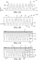
- An image of the separably mated stem-well film was shown in FIG. 4 , where the stem film was peeling away from the well film by applying a separation force at a peripheral edge of the stem film.
- a 3 cm by 3 cm piece of the stem-well film of Example 1 or 2 was mounted to the bottom of a 60 mm by 15 mm plastic Petri dish (VWR, Radnor, PA) using a double sided acrylate adhesive tape 3M 9969 Transfer Adhesive (3M Company, St. Paul, MN) and submerged in Butterfield's buffer (3M Company, St. Paul, MN) to which methylene blue (Sigma Aldrich Co., St. Louis, MO) had been added to a final concentration of about 1 g/L. Using a metal fine tip tweezers, the stem film was peeled off and discarded while the construction was submerged in the liquid sample.
- 3M 9969 Transfer Adhesive 3M Company, St. Paul, MN
- Butterfield's buffer 3M Company, St. Paul, MN
- methylene blue Sigma Aldrich Co., St. Louis, MO
- the cover tape had biaxially oriented polypropylene of about 0.05 mm (2 mil) thickness coated with a water-insoluble, silicone based pressure sensitive adhesive, silicone polyurea, of about 0.05 mm (2 mil) thickness.
- the adhesive was described in U.S. Patent Nos. 5,461,134 (Leir et al. ) and 6,007,914 (Joseph et al. ).
- the well film was then placed on the stage of a microscope (Discovery.V8 SteREO, Carl Zeiss Microscopy, Oberkochen, Germany) and the wells were examined to determine the extent of filling using the blue color imparted by the methylene blue dye. Substantially every well in the well film (2232 wells) was completely filled and free of air bubbles either interior to the well or at the well-cover tape interface.
Description
- This disclosure relates to a method of partitioning an aqueous test sample including separating mated stem-well films.
- A wide variety of methods and devices have been developed for segmenting an aqueous test sample into a large number of smaller discrete volumes. By using a sample partitioning device, a series of tiny compartments can be filled with the aqueous test sample where desired reaction or growth can occur and be detected much more rapidly than the same reaction or growth in a larger volume. A number of techniques have been disclosed such as, for example, the techniques described in
US Patent No. 4,678,695 (Tung et al. ),US Patent No. 5,824,390 (Ochi et al. ),US Patent No. 5,474 ,827 (Crandall et al. ),US Patent No. 5,812,317 (Billingsley et al. ),US Patent No. 7,723,452 (Hooftman et al. ),US 6,172,810 (Fleming et al. ),US Patent No. 6,355,302 (Vandenberg et al. ), etc. -
US 2015/087078 A1 discloses well seals for microtiter plates that can be manipulated by a pipette or a pipette array. - Described herein are methods of making sample partitioning devices, and methods of using them. A sample partitioning device includes a first film including an array of discrete stems each extending from a first major surface thereof, and a second film including an array of discrete wells formed into a second major surface thereof. The stems of the first film and the wells of the second film are mated with each other. The mated stems and wells are separable from each other, and during the removal of the stems from the wells, one or more voids are created inside the wells that are capable of suctioning an aqueous test sample into the wells.
- The present invention describes a method of partitioning an aqueous test sample, the method including providing a first film comprising an array of discrete stems each extending away from a first major surface thereof, and providing a second film comprising an array of wells that are mated with the stems of the first film. The mated stems and wells are submerged in an aqueous test sample. The first film is then separated from the second film to remove the stems from the wells. During the removal of the stems, one or more voids are created inside the wells to suction the aqueous test sample into the wells and fill the wells.
- The sample partitioning device can be produced by a method including providing a first film comprising an array of discrete stems each extending away from a first major surface thereof. A polymeric composition is provided on the first major surface of the first film. The polymeric composition is cured to form a continuous second film including an array of discrete wells corresponding to the stems in negative relief. The stems and wells are separably mated where an outer surface and an inner surface thereof are in direct physical contact.
- The present application may be more completely understood in consideration of the following detailed description of various embodiments of the disclosure in connection with the accompanying drawings.
-
FIG. 1A illustrates a cross-sectional view of a stem film including an array of stems, according to one embodiment. -
FIG. 1B illustrates a cross-sectional view of a sample partitioning device including the stem film ofFIG. 1A and a well film formed thereon to mate with the stem film, according to one embodiment. -
FIG. 2A illustrates the sample partitioning device ofFIG. 1B submerged in an aqueous test sample solution, according to one embodiment. -
FIG. 2B illustrates the separation of the stem film from the well film to fill the wells with the aqueous test sample solution, according to the embodiment ofFIG. 2A . -
FIG. 2C illustrates the well film ofFIG. 2A including an array of discrete wells filled with the aqueous test sample solution after the removal of the stem film. -
FIG. 3 illustrates the filled well film ofFIG. 2C laminated with a cover film, according to one embodiment. -
FIG. 4 illustrates an image of an article where a stem film is separating from a mated well film, according to Example 2. - In the following description of the illustrated embodiments, reference is made to the accompanying drawings, in which is shown by way of illustration, various embodiments in which the disclosure may be practiced. It is to be understood that the embodiments may be utilized and structural changes may be made without departing from the scope of the claimed invention. The figures are not necessarily to scale. Like numbers used in the figures refer to like components. However, it will be understood that the use of a number to refer to a component in a given figure is not intended to limit the component in another figure labeled with the same number.
- Methods of making sample partitioning devices and using the articles are described herein. The present disclosure describes sample partitioning devices which include a first film, e.g., a stem film including an array of discrete stems each extending from a first major surface thereof, and a second film, e.g., a well film including an array of discrete wells formed into a second major surface thereof. The stems of the stem film and the wells of the well film are separably mated with each other. In some cases, when the mated stems and wells are submerged in a quantity of aqueous solution, during the removal of the stems from the wells, one or more voids are created inside the wells to suction the aqueous solution into the wells.
-
FIG. 1A illustrates a cross-sectional view of astem film 10, according to one embodiment. Thestem film 10 includes abase 12 and an array of discrete posts or stems 14 integral with thebase 12. Eachposts 14 extend away from amajor surface 122 thereof and extend between afirst end 142 and asecond end 144 thereof. Thefirst ends 142 are connected to thebase 12. Theposts 14 and thebase 12 may be made of the same material or different materials and integral as one piece. - In the embodiment illustrated in
FIG. 1A , theposts 14 each have a conical shape that is generally circular in cross section. It is to be understood that theposts 14 may have various cross sectional shapes such as, for example, a circular shape, an oval shape, a square shape, a polygon shape such as a hexagon, etc. Theposts 14 are slightly tapered to a smaller cross sectional area adjacent thesecond end 144 than at thefirst end 142. A draft angle is the included angle between theside surfaces 146 and the z-axis of theposts 14. The draft angle within an appropriate range may help facilitate removal of the posts from cavities such as in a molding process of producing thestem film 10. The draft angle may also affect the separation of theposts 14 and wells mated with theposts 14, and thus affect the suction of liquid into the wells when separating the mated posts and wells, which will be discussed further below. In some embodiments, the draft angle may be, for example, no greater than 30°, no greater than 15°, no greater than 10°, or greater than 8 °, or no greater than 5 °. In some embodiments, the draft angle can be, for example, no less than 0.5, no less than 1 °, no less than 2 °, or no less than 3 °. In some embodiments, a useful range of the draft angle may be between 1° and 10°. It is understood that the shape of the posts may not be symmetrical, and thus may have more than one draft angle depending upon from which side of the post it is measured. In some embodiments it may even be advantageous to provide a draft angle that is greater on one side of the post (and well) to facilitate increased ease of removing the stem film from the well film in a particular preselected direction. - The
posts 14 have a height "H" which is a longitudinal distance between thefirst end 142 and thesend end 144 of the respective posts 14. The first and second ends 142 and 144 have a first end width "W1" and a second end width "W2", respectively. The first width "W1" and the second end width "W2" are representative lateral dimensions of the cross sections of theposts 14 in the respective lateral planes. Theposts 14 each have a tapered shape so that W1 is greater than the corresponding W2. The height "H" of theposts 14 can be, for example, no less than 10 microns, no less than 20 microns, no less than 50 microns, or no less than 100 microns. The height of theposts 14 can be, for example, no greater than 2 mm, no greater than 1 mm, no greater than 800 microns, or no greater than 500 microns. The average end width (W1+W2)/2 can be, for example, no less than 5 microns, no less than 10 microns, no less than 20 microns, or no less than 50 microns. The average end width (W1+W2)/2 can be, for example, no greater than 1 mm, no greater than 500 microns, no greater than 300 microns, or no greater than 200 microns. - An aspect ratio of the
posts 14 can be defined as a ratio between an average longitudinal dimension (e.g., along the direction generally perpendicular to the film 10) and an average lateral dimension (e.g., along a lateral, in plane direction generally parallel to the film 10). Theposts 14 have an aspect ratio that can be defined by H/((W1+W2)/2). The aspect ratio of theposts 14 may also affect the separation of theposts 14 from wells mated with theposts 14, and thus affect the suction of liquid into the wells when separating the mated posts and wells, which will be discussed further below. In some embodiments, the aspect ratio H/((W1+W2)/2) can be, for example, 0.5 or more, 1 or more, or 2 or more. In some embodiments, the aspect ratio H/((W1+W2)/2) can be, for example, 10 or less, 8 or less, or 6 or less. In some embodiments, the aspect ratio H/((W1+W2)/2) can be between 0.5 and 6. - The array of
posts 14 are arranged in two dimensions with columns and rows on thebase 12. Theposts 14 are discrete and separated with each other bycontinuous cavities 16 therebetween. A pin density of theposts 14 is defined as the number of posts per area on thebase 12. In some embodiments, the pin density can be 50 pins/inch2 (ppi) or more, 100 ppi or more, 500 ppi or more, or 1000 ppi or more. The pin density can be 20,000 ppi or less, 10,000 ppi or less, 5000 ppi or less, or 3000 ppi or less. In some embodiments, the pin density can be between 100 and 10,000 ppi. - In some embodiments, the
stem film 10 including the stems orposts 14 can be prepared by molding and curing a polymerizable resin. In some embodiments, the polymerizable resin may include, for example, olefin polymer including polypropylene, polyethylene and copolymers, silicone polymer, polyurethane, polyvinyl chloride, ethylene-vinyl acetate polymer, (meth)acrylic polymer, polyamide, polyester, poly(styrene-acrylonitrile), poly(acrylonitrile-butadiene-styrene), etc. In some embodiments, the polymerizable resin can include, for example, a combination of first and second polymerizable components selected from, for example, (meth)acrylate monomers, (meth)acrylate oligomers, and mixtures thereof. As used herein, "monomer" or "oligomer" is any substance that can be converted into a polymer. The term "(meth)acrylate" refers to both acrylate and methacrylate compounds. In some cases, the polymerizable composition can include a (meth)acrylated urethane oligomer, (meth)acrylated epoxy oligomer, (meth)acrylated polyester oligomer, a (meth)acrylated phenolic oligomer, a (meth)acrylated acrylic oligomer, and mixtures thereof. The polymerizable resin can be a radiation curable polymeric resin, such as an ultraviolet (UV) curable resin. It is to be understood that thestem film 10 can be formed by any suitable processes including, for example, injection, molding, hot embossing, UV embossing, roll-to-roll embossing, etc. - In some embodiments, the
posts 14 each may have a molecular orientation as evidenced by a birefringence value of at least 0.001. Such molecular orientation may provide theposts 14 with significantly greater stiffness and durability, as well as greater tensile and flexural strength, than would be achievable without such orientation. An exemplary molding process of making posts or stems having a molecular orientation is described inUS Patent No. 5,077,870 (Melbye et al. ). -
FIG. 1B illustrates a cross-scctional view of asample partitioning device 100 including thestem film 10 ofFIG. 1A and awell film 20 formed thereon, according to one embodiment. Afilm forming material 22 is applied onto themajor surface 122 of thestem film 10. Thefilm forming material 22 fills thecavities 16 between theposts 14 to form acontinuous well film 20. Thewell film 20 may have a thickness of, for example, from several microns to several centimeters, from about 2 microns to about 5 mm, or from 10 microns to about 2 mm. In some embodiments, thefilm forming material 22 may include one or more curable polymeric materials such as, for example, (meth)acrylic polymer, polyvinyl acetal resin, polyvinylchloride, polyurethane, silicone polymer, styrenic polymer, vinyl ether polymer, vinylpyrrolidone polymer, polyester including lactone-based polymer, cyclic ether-based polymer including epoxy resins, ring-opening metathesis polymer, etc. Thefilm forming material 22 can be cured by, for example, radiation or heating, to form a radiation cured polymeric film or a thermally cured polymeric film. It is to be understood that in some embodiments, the curablefilm forming material 22 may be cured at temperatures that are low enough to avoid causing possible damage to thestem film 10. In this regard, to be compatible with certain stem films that may not sustain high curing temperatures, it may be preferable to exclude certain thermoplastic resins to be used as film forming material which need high temperature and/or pressure to process, including for example, polypropylene, polyethylene, polyamides (such as nylon 6 and nylon 6,6), polyesters (such as polyethylene terephthalate, polybutylene terephthalate, or elastomers commercially available under the trade designation HYTREL), polytetrafluoroethylene, polyacetal (such as the polymer commercially available under the trade designation DELRIN), acrylonitrile-butadiene-styrene (ABS) copolymers, polyvinylchloride, polycarbonate, thermoplastic polyurethanes, and some thermoplastic acrylic polymers such as poly(methyl methacrylate) as well as blends and copolymers thereof. - The formed
sample partitioning device 100 includes the mated stem andwell films well film 20 has a firstmajor surface 202 that conforms with themajor surface 122 of thestem film 10. The array ofposts 14 of thestem film 10 projects into the firstmajor surface 202 of thewell film 20 and is completely encapsulated by the material of thewell film 20. When the first andsecond films major surface 202 of thewell film 20 that can be filled with an aqueous test sample solution to be partitioned, for example, when the first andsecond films posts 14 in negative relief. In some embodiments, theposts 14 may substantially fill the well. For example, about 90% or more, about 95% or more, about 98% or more, or about 99.9% or more space of a well may be filled by therespective post 14. In some embodiments, the well may be completely filled by thepost 14 with no air (e.g., less than 0.1%, less than 0.05%, or less than 0.01% of the well space) trapped therein. A well density of the wells is defined as the number of wells per area, corresponding to the pin density of the posts. In some embodiments, the well density can be 50 wells/inch2 (wpi) or more, 100 wpi or more, 500 wpi or more, or 1000 wpi or more. The well density can be 20,000 wpi or less, 10,000 wpi or less, 5000 wpi or less, or 3000 wpi or less. In some embodiments, the pin density can be between 100 wpi and 10,000 wpi. - Upon the formation of the
well film 20 on thestem film 10, theposts 14 and the wells are separably mated where the outer surface (e.g., theside surface 146 and thesecond end 144 shown inFIG. 1A ) of theposts 14 is in direct, intimate physical contact with an inner surface of the wells. In some embodiments, thewell film 20 may be formed on thestem film 10 by a replication process where the geometry of the firstmajor surface 122 of thestem film 10 is transferred to themajor surface 202 of thewell film 20 to form the directly mated posts and wells. Thefilm forming material 22 may be brought into a viscous or fluid state before it is brought into contact with the firstmajor surface 122 of thestem film 10. During the period of contact between thefilm forming material 22 and thestem film 10, pressure, temperature or other relevant process parameters may be controlled in such a way that thefilm forming material 22 copies the geometry and somehow subsequently gains mechanical strength (e.g. by solidification, polymerization, etc.). In some embodiments, the viscous or fluid state of thefilm forming material 22 can expel air from the contacting surface with thestem film 10, thereby providing the direct, intimate physical contact between themajor surface 122 of thestem film 10 and themajor surface 202 of the formed well film without trapping a significant amount of air therebetween. - The mated
stem film 10 and well film 20 are separable by, for example, peeling. It is to be understood that the pairing of materials for the stem film and the well film need to be compatible with each other. One useful pairing of materials include a polypropylene stem web with photo-cured acrylate-based well film. It was found in the disclosure that polyethylene and polyurethane materials may be incompatible with some UV-cured acrylate polymers where posts may become fused to the wells and it may be difficult to separate the mated posts and wells. - The
sample partitioning device 100 may include optional layer(s) laminated onto theback surface 124 of thestem film 10 or theback surface 204 of thewell film 20. In some embodiments, a double coated tape or transfer adhesive layer can be laminated onto theback surface back surface stem film 10 for manually handling thestem film 10, for example, when manually removing thestem film 10 from thewell film 20 by applying a separation force at a peripheral edge of thestem film 10 and peeling the stem film away from thewell film 20. The tab can be attached to the peripheral edge of thestem film 10 and have suitable shapes for handling. - In some embodiments, the sample partitioning devices may be produced in the form of a continuous web by a roll-to-roll process. Additional layers such as, for example, transfer adhesive layer, liner layer, and tabs for manual handling, etc., may be laminated or connected to the surfaces of the devices. The web may be wound into a roll, and can be cut into pieces before using.
-
FIGS. 2A-C illustrate how to use thesample partitioning device 100 ofFIG. 1B to partition an aqueoustest sample solution 2, according to one embodiment. Thesample partitioning device 100 is submerged into theaqueous test sample 2, as shown inFIG. 2A . Thestem film 10 is then removed from thewell film 20 to separate the matedsurfaces posts 14 andwells 24. As shown inFIG. 2B , thestem film 10 is peeled away from thewell film 20. During the peeling, the originally contactedsurfaces space 3 therebetween to allow the aqueous test sample to flow into the space. During the separation of pairings of matedposts 14 andwells 24, one or more voids 244 can be instantaneously created inside thewells 24 to suction the aqueous test sample from theadjacent space 3 between thesurfaces wells 24. When theposts 14 are completely removed from therespective wells 24, thewells 24 are filled with theaqueous test sample 2, without the entrapment of air bubbles. After the removal of thestem film 10, themajor surface 202 and thewells 24 filled with liquid sample can be revealed. - The separation of the mated
posts 14 andwells 24, and thus the filling of thewells 24 with the aqueous test sample solution may be adjusted by considering technical aspects including, for example, geometry factors of theposts 14, the pin density of the posts 14 (or the well density of the wells 24), material properties of theposts 14 andwells 24, etc. While not wishing to be bound by theory, it is believed that (i) when the aspect ratio of theposts 14 increases, (ii) when the pin density of theposts 14 increases, or (iii) when the draft degree of theposts 14 decreases, a higher peeling force may be required to peel thestem film 10 away from the matedwell film 20. Also, it is to be understood that thestem film 10 including theposts 14 has sufficient flexibility and tenacity to prevent breaking during the removal from thewells 24. - As shown in
FIG. 2C , theaqueous test sample 2 is partitioned into the array ofwells 24. Thewell film 20 submerged in theaqueous test sample 2 can then be removed therefrom by, for example, decanting or aspiration. In the depicted embodiments, thewells 24 are discrete and separated with each other by surroundingwalls 222. It is to be understood that in some embodiments, adjacent wells may be selectively formed in fluid communication via, for example, fluid channels formed on the top surface of the surroundingwalls 222. In some embodiments, the top surface of the surroundingwalls 222 may be hydrophobic which can help partition liquid intoadjacent wells 24 and/or prevent possible crosstalk between adjacent wells. - While the portioning process shown in
FIGS. 2A-C is conducted by submerging thesample partitioning device 100 in an aqueous test sample, it is to be understood that the aqueous test sample may be provided in various ways not according to the invention For example, in some embodiments not according to the invention, an aqueous solution can be provided by ejecting into thespace 3 between themajor surface 122 of thestem film 10 and thesurface 202 of thewell film 20 during the separation of thefilms space 3. - After the
aqueous solution 2 is partitioned into the array ofwells 24, thewells 24 of thewell film 20 can be sealed with acover layer 30. As shown inFIG. 3 , thecover layer 30 is laminated over thewells 24 to prevent possible crosstalk and evaporation. In some embodiments, thecover layer 30 can be laminated after an excess sample is aspirated away. In some embodiments, thecover layer 30 may include, for example, a pressure-sensitive adhesive (PSA) sheet that may include a support and a PSA layer. In some embodiments, the PSA layer may be laminated with a release liner which can be removed from the PSA sheet before use. - The sample partitioning devices described herein such as the
sample partitioning device 100 ofFIG. 1B may be treated before use. In some embodiments, the sample partitioning device may be treated with gamma irradiation (e.g., 50 kgy) for sterilization. - The sample partitioning devices of this disclosure can be used for a variety of applications such as in molecular biology and microbiology. Various unexpected results and advantages are obtained in exemplary embodiments of the disclosure. One such advantage of exemplary embodiments of the present disclosure is that an aqueous sample solution can be partitioned into wells or compartments of a well film where the geometry, size and shape, and volume of the compartments can be customized by controlling the geometry of the corresponding posts or stems of a stem film on which the well film is formed.
- These examples are merely for illustrative purposes only and are not meant to be limiting on the scope of the appended claims.
- A polypropylene stem film was produced by a molding process. The stem film has a structure similar as the
stem film 10 shown inFIG. 1A , and includes an array of conical posts which are 270 microns tall, 100 microns radius at the base, and 85 microns radius at the apex with a generally flat top. A film forming material was applied to the polypropylene stem film to form a stem-well film such as shown inFIG. 1B . The film forming material has a silicone composition that is commercially available from Dow Corning Corporation (Midland, MI, USA) under the trade designation SYLGARD 184. The silicone composition was cured at room temperature or elevated temperature to from a Polydimethylsiloxane (PDMS) well film that was separably mated with the polypropylene stem film. The formed wells of the well film each have a volume of about 7.27 nanoliters. - The stem film was the same as in Example 1. The film forming material was prepared as following. Mixtures of 2-Ethylhexyl acrylate (180 grams), isobornyl acrylate (120 grams), Polyvinyl butyral ("PVB") resin (45 grams), hexanediol diacrylate (30 grams), and IRG 651 photoinitiator (0.66 grams) were added to quart jars. The jars and contents were placed in a
MAX 20 WHITE SPEEDMIXER (available from FleckTek, Inc., Landrum, SC) and mixed at 3500 RPM for 1 minute. The mixture was degassed at -20 inches of mercury (-6.8 kPa) for 5 minutes. Polyvinyl butyral ("PVB") resin is commercially available from Kuraray under the trade designation "Mowital™" and Solutia under the trade designation "Butvar™". IRG 651 photoinitiator is commercially available under the trade name IRGACURE 651 or ESACURE KB-1 photoinitiator (Sartomer Co., West Chester, PA). The mixtures were applied to the stem film at a thickness ranging from about 30 to 300 microns and under a nitrogen atmosphere cured by further exposure to UVA light. An image of the separably mated stem-well film was shown inFIG. 4 , where the stem film was peeling away from the well film by applying a separation force at a peripheral edge of the stem film. - A 3 cm by 3 cm piece of the stem-well film of Example 1 or 2 was mounted to the bottom of a 60 mm by 15 mm plastic Petri dish (VWR, Radnor, PA) using a double sided acrylate adhesive tape 3M 9969 Transfer Adhesive (3M Company, St. Paul, MN) and submerged in Butterfield's buffer (3M Company, St. Paul, MN) to which methylene blue (Sigma Aldrich Co., St. Louis, MO) had been added to a final concentration of about 1 g/L. Using a metal fine tip tweezers, the stem film was peeled off and discarded while the construction was submerged in the liquid sample. Following removal of the stem film, the remaining liquid sample was decanted and a cover tape was applied. The cover tape had biaxially oriented polypropylene of about 0.05 mm (2 mil) thickness coated with a water-insoluble, silicone based pressure sensitive adhesive, silicone polyurea, of about 0.05 mm (2 mil) thickness. The adhesive was described in
U.S. Patent Nos. 5,461,134 (Leir et al. ) and6,007,914 (Joseph et al. ). The well film was then placed on the stage of a microscope (Discovery.V8 SteREO, Carl Zeiss Microscopy, Oberkochen, Germany) and the wells were examined to determine the extent of filling using the blue color imparted by the methylene blue dye. Substantially every well in the well film (2232 wells) was completely filled and free of air bubbles either interior to the well or at the well-cover tape interface.
Claims (12)
- A method of partitioning an aqueous test sample, the method comprising:providing a first film comprising an array of discrete stems each extending away from a first major surface thereof;providing a second film comprising an array of wells that are mated with the stems of the first film, characterized bysubmerging the mated stems and wells in an aqueous test sample;separating the first film from the second film to remove the stems from the wells; andduring the removal of the stems, creating one or more voids inside the wells to suction the aqueous test sample into the wells and fill the wells.
- The method of claim 1, further comprising laminating over the wells on the second major surface of the second film with a cover film after filling the wells.
- The method of claim 1 or 2, wherein providing the second film comprises applying a film making material to the first major surface of the first film to form the wells mated with the stems.
- The method of claim 3 wherein the film making material comprises a curable polymeric material that is applied in a viscous or fluid state, and the method further comprises curing or drying the film making material.
- The method of any one of the preceding claims, wherein at least one of the stems has a shape of conical post that is tapered away from the first major surface with a draft angle between 1 and 30 degrees.
- The method of any one of the preceding claims, wherein the second major surface of the second film is hydrophobic.
- The method of any one of the preceding claims, wherein the wells have an average volume of 1 to 500 nanoliters.
- The device of any one of claims 1-6, wherein the array of stems has a density between 100 and 10,000 pins/inch2 (ppi).
- The method of any one of the preceding claims, wherein the first film comprises one or more of olefin polymer including polypropylene, polyethylene and copolymer, silicone polymer, polyurethane, polyvinyl chloride, ethylene-vinyl acetate polymer, (meth)acrylic polymer, polyamide, polyester, poly(styrene-acrylonitrile), and poly(acrylonitrile-butadiene-styrene).
- The method of any one of the preceding claims, wherein the second film comprises one or more of (meth)acrylic polymer, polyvinyl acetal resin, polyvinylchloride, polyurethane, silicone polymer, styrenic polymer, vinyl ether polymer, vinylpyrrolidone polymer, polyester including lactone-based polymer, cyclic ether-based polymer including epoxy resin, and ring-opening metathesis polymer
- The method of any one of the preceding claims, wherein at least one of the first and second films comprises polydimethylsiloxane (PDMS).
- The method of any one of the preceding claims, wherein at least one of the first and second films comprises a cured acrylate polymer.
Applications Claiming Priority (2)
| Application Number | Priority Date | Filing Date | Title |
|---|---|---|---|
| US201562270757P | 2015-12-22 | 2015-12-22 | |
| PCT/US2016/067437 WO2017112564A1 (en) | 2015-12-22 | 2016-12-19 | Stem-well films for sample partitioning |
Publications (2)
| Publication Number | Publication Date |
|---|---|
| EP3393663A1 EP3393663A1 (en) | 2018-10-31 |
| EP3393663B1 true EP3393663B1 (en) | 2021-04-14 |
Family
ID=57915061
Family Applications (1)
| Application Number | Title | Priority Date | Filing Date |
|---|---|---|---|
| EP16831789.9A Active EP3393663B1 (en) | 2015-12-22 | 2016-12-19 | Method of partitioning an aqueous test sample |
Country Status (5)
| Country | Link |
|---|---|
| US (1) | US11207690B2 (en) |
| EP (1) | EP3393663B1 (en) |
| JP (1) | JP2019508222A (en) |
| CN (1) | CN108430638B (en) |
| WO (1) | WO2017112564A1 (en) |
Families Citing this family (9)
| Publication number | Priority date | Publication date | Assignee | Title |
|---|---|---|---|---|
| CN107001761B (en) | 2014-12-08 | 2020-06-16 | 3M创新有限公司 | Acrylic polyvinyl acetal film, composition, and heat-bondable article |
| WO2017112453A2 (en) | 2015-12-22 | 2017-06-29 | 3M Innovative Properties Company | Acrylic polyvinyl acetal films comprising a second layer |
| EP3393795A2 (en) | 2015-12-22 | 2018-10-31 | 3M Innovative Properties Company | Acrylic films comprising a structured layer |
| AU2016378200B2 (en) | 2015-12-22 | 2019-08-15 | 3M Innovative Properties Company | Acrylic polyvinyl acetal graphic films |
| JP7030054B2 (en) | 2015-12-22 | 2022-03-04 | スリーエム イノベイティブ プロパティズ カンパニー | Acrylic polyvinyl acetal film with adhesive layer |
| WO2017116891A1 (en) | 2015-12-28 | 2017-07-06 | 3M Innovative Properties Company | Cartridges for sample partitioning |
| WO2018152467A1 (en) | 2017-02-20 | 2018-08-23 | 3M Innovative Properties Company | Self-wetting adhesive composition |
| CN110325611A (en) | 2017-02-20 | 2019-10-11 | 3M创新有限公司 | From wet adhesive composition |
| BR112022025863A2 (en) | 2020-06-19 | 2023-03-07 | 3M Innovative Properties Company | DEVICE FOR CULTIVATION OF MICROORGANISMS |
Family Cites Families (43)
| Publication number | Priority date | Publication date | Assignee | Title |
|---|---|---|---|---|
| US5474A (en) | 1848-03-14 | Cooking-stove | ||
| US827A (en) | 1838-07-09 | Machine fob stbetchlncr hobse-collabs | ||
| US4678695A (en) | 1985-12-23 | 1987-07-07 | Minnesota Mining And Manufacturing Company | Encapsulated flattop retroreflective sheeting and method for producing the same |
| US5214119A (en) | 1986-06-20 | 1993-05-25 | Minnesota Mining And Manufacturing Company | Block copolymer, method of making the same, dimaine precursors of the same, method of making such diamines and end products comprising the block copolymer |
| US5077870A (en) | 1990-09-21 | 1992-01-07 | Minnesota Mining And Manufacturing Company | Mushroom-type hook strip for a mechanical fastener |
| FR2708286B1 (en) | 1993-07-28 | 1995-10-20 | Rambach Alain | Method of identifying microorganisms with at least two chromogens. |
| US5518892A (en) | 1994-02-23 | 1996-05-21 | Idexx Laboratories, Inc. | Apparatus and method for quantification of biological material in a liquid sample |
| US5474827A (en) | 1994-03-23 | 1995-12-12 | Minnesota Mining And Manufacturing Company | Retroreflective article and method of making the same |
| US5824390A (en) | 1994-07-22 | 1998-10-20 | Nippon Carbide Kogyo Kabushiki Kaisha | Method for producing retroreflective sheeting using a coupling agent |
| US5812317A (en) | 1995-10-26 | 1998-09-22 | Minnesota Mining And Manufacturing Company | Exposed lens retroreflective article having a polymeric intermediate layer disposed between microspheric and reflective layers |
| US6696286B1 (en) | 1997-04-09 | 2004-02-24 | 3M Innovative Properties Company | Method and devices for detecting and enumerating microorganisms |
| US6391578B2 (en) | 1997-04-09 | 2002-05-21 | 3M Innovative Properties Company | Method and devices for partitioning biological sample liquids into microvolumes |
| NZ504223A (en) * | 1997-10-27 | 2001-10-26 | Idexx Lab Inc | Device and methods for determination of the presence or amount of an analyte or microorganism in a solution |
| US6007914A (en) | 1997-12-01 | 1999-12-28 | 3M Innovative Properties Company | Fibers of polydiorganosiloxane polyurea copolymers |
| US6458533B1 (en) | 1997-12-19 | 2002-10-01 | High Throughput Genomics, Inc. | High throughput assay system for monitoring ESTs |
| US6063579A (en) * | 1998-10-30 | 2000-05-16 | Incyte Pharmaceuticals, Inc. | Alignment mechanism |
| US6172810B1 (en) | 1999-02-26 | 2001-01-09 | 3M Innovative Properties Company | Retroreflective articles having polymer multilayer reflective coatings |
| US6355302B1 (en) | 1999-12-10 | 2002-03-12 | 3M Innovative Properties Company | Continuous process for making high performance retroreflective fabric |
| AU3607301A (en) | 2000-03-03 | 2001-09-12 | Kyowa Hakko Kogyo Kk | Gene recombinant antibody and its fragment |
| CA2402591A1 (en) * | 2000-03-28 | 2001-10-04 | Caliper Technologies Corp. | Methods of reducing fluid carryover in microfluidic devices |
| US6627159B1 (en) | 2000-06-28 | 2003-09-30 | 3M Innovative Properties Company | Centrifugal filling of sample processing devices |
| NL1017374C2 (en) | 2001-02-15 | 2002-08-16 | Univ Delft Tech | Device for carrying out a reaction, as well as a method for carrying out a reaction in the device. |
| US6977722B2 (en) * | 2001-06-29 | 2005-12-20 | Meso Scale Technologies, Llc. | Assay plates, reader systems and methods for luminescence test measurements |
| US7037580B2 (en) | 2001-09-25 | 2006-05-02 | Ali Razavi | Pattern adhesive sealing films and mats for multi-well plates |
| JP3696141B2 (en) | 2001-09-27 | 2005-09-14 | 株式会社東芝 | Chemical analyzer, analysis method |
| US7582472B2 (en) | 2003-08-26 | 2009-09-01 | Smith Kenneth E | Apparatus and method for liquid sample testing |
| US7247386B2 (en) | 2003-12-23 | 2007-07-24 | 3M Innovative Properties Company | Composition of an oligomeric fluorosilane and surface treatment of retroreflective sheet |
| CN1997454B (en) * | 2004-05-02 | 2010-06-16 | 弗卢丁公司 | Thermal reaction device and method for using the same |
| GB0505379D0 (en) * | 2005-03-16 | 2005-04-20 | Robio Systems Ltd | Cellular entity maturation and transportation systems |
| KR100738087B1 (en) * | 2005-12-22 | 2007-07-12 | 삼성전자주식회사 | Quantitative dispensing apparatus for cell using liquid droplet manipulation |
| WO2007081386A2 (en) | 2006-01-11 | 2007-07-19 | Raindance Technologies, Inc. | Microfluidic devices and methods of use |
| US9074242B2 (en) | 2010-02-12 | 2015-07-07 | Raindance Technologies, Inc. | Digital analyte analysis |
| US20080293127A1 (en) * | 2007-05-22 | 2008-11-27 | Applera Corporation | Method to Render Pressure Sensitive Adhesive Compatible with Polymerase Chain Reaction Systems |
| WO2011063332A2 (en) * | 2009-11-23 | 2011-05-26 | 3M Innovative Properties Company | Microwell array articles and methods of use |
| DE102010008036A1 (en) * | 2010-02-05 | 2011-08-11 | Eppendorf AG, 22339 | microtiter plate |
| US20110263461A1 (en) | 2010-04-23 | 2011-10-27 | Kumar Kastury | Methods and devices for collecting samples in a high throughput format |
| WO2012076636A1 (en) * | 2010-12-08 | 2012-06-14 | Novozymes A/S | Microplate sampling adapter |
| US20140287423A1 (en) | 2011-10-28 | 2014-09-25 | Life Technologies Corporaton | Device and method for apportionment and manipulation of sample volumes |
| DE102011119174A1 (en) * | 2011-11-23 | 2013-05-23 | Inheco Industrial Heating And Cooling Gmbh | Vapor Chamber |
| JP2015534824A (en) * | 2012-11-07 | 2015-12-07 | ライフ テクノロジーズ コーポレーション | Case for containing biological sample and corresponding method of use |
| JP6067885B2 (en) * | 2013-01-24 | 2017-01-25 | サビック グローバル テクノロジーズ ベスローテン フェンノートシャップ | Polycarbonate microfluidic article |
| US20150087078A1 (en) * | 2013-09-24 | 2015-03-26 | Accel Biotech, Inc. | Well seals in pipette workstations |
| JP6709221B2 (en) | 2014-12-08 | 2020-06-10 | スリーエム イノベイティブ プロパティズ カンパニー | Acrylic polyvinyl acetal film and composition |
-
2016
- 2016-12-19 US US16/064,064 patent/US11207690B2/en active Active
- 2016-12-19 WO PCT/US2016/067437 patent/WO2017112564A1/en unknown
- 2016-12-19 JP JP2018532724A patent/JP2019508222A/en not_active Ceased
- 2016-12-19 EP EP16831789.9A patent/EP3393663B1/en active Active
- 2016-12-19 CN CN201680075014.7A patent/CN108430638B/en active Active
Non-Patent Citations (1)
| Title |
|---|
| None * |
Also Published As
| Publication number | Publication date |
|---|---|
| JP2019508222A (en) | 2019-03-28 |
| CN108430638A (en) | 2018-08-21 |
| US11207690B2 (en) | 2021-12-28 |
| US20190001326A1 (en) | 2019-01-03 |
| CN108430638B (en) | 2021-06-08 |
| WO2017112564A1 (en) | 2017-06-29 |
| EP3393663A1 (en) | 2018-10-31 |
Similar Documents
| Publication | Publication Date | Title |
|---|---|---|
| EP3393663B1 (en) | Method of partitioning an aqueous test sample | |
| EP3500662B1 (en) | High-throughput system and method for the temporary permeabilization of cells | |
| AU2016338907B2 (en) | Systems and methods for making and using gel microspheres | |
| JP2018538151A (en) | Polymer membrane having through-hole and method for producing the same | |
| Park et al. | Pumpless, selective docking of yeast cells inside a microfluidic channel induced by receding meniscus | |
| US20170156623A1 (en) | Self-adhesive microfluidic and sensor devices | |
| KR102389946B1 (en) | Coating method using particle alignment | |
| WO2017130044A1 (en) | Microfluidic aliquoting for single-cell isolation | |
| EP3395939B1 (en) | Cell sorting, culture, and growth vessel; and cell sorting, culture, and growth method | |
| Cho et al. | Microfluidic platforms with monolithically integrated hierarchical apertures for the facile and rapid formation of cargo-carrying vesicles | |
| EP3275502A1 (en) | Method of producing transdermal absorption sheet | |
| JP5998464B2 (en) | Method for producing cell culture vessel | |
| EP2512674B1 (en) | Process for assembling elements containing biological substances | |
| WO2017061528A1 (en) | Platelet production-use device, platelet production apparatus, and platelet production method | |
| CN108545692B (en) | Method for manufacturing microfluidic chip with inner wall of channel coated with parylene | |
| CN203976784U (en) | micro-fluidic type single cell separator | |
| CN104152345A (en) | Microfluidic type single-cell separator | |
| KR101053772B1 (en) | Forming module for manufacturing microfluidic chip mold, method for manufacturing microfluidic chip mold using the same and microfluidic chip mold manufactured by the same | |
| Gregory et al. | High yield fabrication of multilayer polydimethylsiloxane devices with freestanding micropillar arrays | |
| JP4714805B2 (en) | Microchip | |
| EP3990892A1 (en) | Articles having conformal layers and methods of making same | |
| JP5919776B2 (en) | Method for producing cell culture vessel | |
| JP5176032B2 (en) | Microwell array chip | |
| JP6638520B2 (en) | Container manufacturing method | |
| WO2023248159A1 (en) | Methods and devices for removing particles from fluids |
Legal Events
| Date | Code | Title | Description |
|---|---|---|---|
| STAA | Information on the status of an ep patent application or granted ep patent |
Free format text: STATUS: UNKNOWN |
|
| STAA | Information on the status of an ep patent application or granted ep patent |
Free format text: STATUS: THE INTERNATIONAL PUBLICATION HAS BEEN MADE |
|
| PUAI | Public reference made under article 153(3) epc to a published international application that has entered the european phase |
Free format text: ORIGINAL CODE: 0009012 |
|
| STAA | Information on the status of an ep patent application or granted ep patent |
Free format text: STATUS: REQUEST FOR EXAMINATION WAS MADE |
|
| 17P | Request for examination filed |
Effective date: 20180612 |
|
| AK | Designated contracting states |
Kind code of ref document: A1 Designated state(s): AL AT BE BG CH CY CZ DE DK EE ES FI FR GB GR HR HU IE IS IT LI LT LU LV MC MK MT NL NO PL PT RO RS SE SI SK SM TR |
|
| AX | Request for extension of the european patent |
Extension state: BA ME |
|
| DAV | Request for validation of the european patent (deleted) | ||
| DAX | Request for extension of the european patent (deleted) | ||
| STAA | Information on the status of an ep patent application or granted ep patent |
Free format text: STATUS: EXAMINATION IS IN PROGRESS |
|
| 17Q | First examination report despatched |
Effective date: 20191009 |
|
| GRAP | Despatch of communication of intention to grant a patent |
Free format text: ORIGINAL CODE: EPIDOSNIGR1 |
|
| STAA | Information on the status of an ep patent application or granted ep patent |
Free format text: STATUS: GRANT OF PATENT IS INTENDED |
|
| INTG | Intention to grant announced |
Effective date: 20201106 |
|
| GRAS | Grant fee paid |
Free format text: ORIGINAL CODE: EPIDOSNIGR3 |
|
| GRAA | (expected) grant |
Free format text: ORIGINAL CODE: 0009210 |
|
| STAA | Information on the status of an ep patent application or granted ep patent |
Free format text: STATUS: THE PATENT HAS BEEN GRANTED |
|
| AK | Designated contracting states |
Kind code of ref document: B1 Designated state(s): AL AT BE BG CH CY CZ DE DK EE ES FI FR GB GR HR HU IE IS IT LI LT LU LV MC MK MT NL NO PL PT RO RS SE SI SK SM TR |
|
| REG | Reference to a national code |
Ref country code: GB Ref legal event code: FG4D |
|
| REG | Reference to a national code |
Ref country code: CH Ref legal event code: EP |
|
| REG | Reference to a national code |
Ref country code: DE Ref legal event code: R096 Ref document number: 602016056204 Country of ref document: DE |
|
| REG | Reference to a national code |
Ref country code: IE Ref legal event code: FG4D |
|
| REG | Reference to a national code |
Ref country code: AT Ref legal event code: REF Ref document number: 1381826 Country of ref document: AT Kind code of ref document: T Effective date: 20210515 |
|
| REG | Reference to a national code |
Ref country code: LT Ref legal event code: MG9D |
|
| REG | Reference to a national code |
Ref country code: AT Ref legal event code: MK05 Ref document number: 1381826 Country of ref document: AT Kind code of ref document: T Effective date: 20210414 |
|
| REG | Reference to a national code |
Ref country code: NL Ref legal event code: MP Effective date: 20210414 |
|
| PG25 | Lapsed in a contracting state [announced via postgrant information from national office to epo] |
Ref country code: LT Free format text: LAPSE BECAUSE OF FAILURE TO SUBMIT A TRANSLATION OF THE DESCRIPTION OR TO PAY THE FEE WITHIN THE PRESCRIBED TIME-LIMIT Effective date: 20210414 Ref country code: FI Free format text: LAPSE BECAUSE OF FAILURE TO SUBMIT A TRANSLATION OF THE DESCRIPTION OR TO PAY THE FEE WITHIN THE PRESCRIBED TIME-LIMIT Effective date: 20210414 Ref country code: NL Free format text: LAPSE BECAUSE OF FAILURE TO SUBMIT A TRANSLATION OF THE DESCRIPTION OR TO PAY THE FEE WITHIN THE PRESCRIBED TIME-LIMIT Effective date: 20210414 Ref country code: BG Free format text: LAPSE BECAUSE OF FAILURE TO SUBMIT A TRANSLATION OF THE DESCRIPTION OR TO PAY THE FEE WITHIN THE PRESCRIBED TIME-LIMIT Effective date: 20210714 Ref country code: AT Free format text: LAPSE BECAUSE OF FAILURE TO SUBMIT A TRANSLATION OF THE DESCRIPTION OR TO PAY THE FEE WITHIN THE PRESCRIBED TIME-LIMIT Effective date: 20210414 Ref country code: HR Free format text: LAPSE BECAUSE OF FAILURE TO SUBMIT A TRANSLATION OF THE DESCRIPTION OR TO PAY THE FEE WITHIN THE PRESCRIBED TIME-LIMIT Effective date: 20210414 |
|
| PG25 | Lapsed in a contracting state [announced via postgrant information from national office to epo] |
Ref country code: SE Free format text: LAPSE BECAUSE OF FAILURE TO SUBMIT A TRANSLATION OF THE DESCRIPTION OR TO PAY THE FEE WITHIN THE PRESCRIBED TIME-LIMIT Effective date: 20210414 Ref country code: RS Free format text: LAPSE BECAUSE OF FAILURE TO SUBMIT A TRANSLATION OF THE DESCRIPTION OR TO PAY THE FEE WITHIN THE PRESCRIBED TIME-LIMIT Effective date: 20210414 Ref country code: NO Free format text: LAPSE BECAUSE OF FAILURE TO SUBMIT A TRANSLATION OF THE DESCRIPTION OR TO PAY THE FEE WITHIN THE PRESCRIBED TIME-LIMIT Effective date: 20210714 Ref country code: PL Free format text: LAPSE BECAUSE OF FAILURE TO SUBMIT A TRANSLATION OF THE DESCRIPTION OR TO PAY THE FEE WITHIN THE PRESCRIBED TIME-LIMIT Effective date: 20210414 Ref country code: PT Free format text: LAPSE BECAUSE OF FAILURE TO SUBMIT A TRANSLATION OF THE DESCRIPTION OR TO PAY THE FEE WITHIN THE PRESCRIBED TIME-LIMIT Effective date: 20210816 Ref country code: GR Free format text: LAPSE BECAUSE OF FAILURE TO SUBMIT A TRANSLATION OF THE DESCRIPTION OR TO PAY THE FEE WITHIN THE PRESCRIBED TIME-LIMIT Effective date: 20210715 Ref country code: LV Free format text: LAPSE BECAUSE OF FAILURE TO SUBMIT A TRANSLATION OF THE DESCRIPTION OR TO PAY THE FEE WITHIN THE PRESCRIBED TIME-LIMIT Effective date: 20210414 Ref country code: IS Free format text: LAPSE BECAUSE OF FAILURE TO SUBMIT A TRANSLATION OF THE DESCRIPTION OR TO PAY THE FEE WITHIN THE PRESCRIBED TIME-LIMIT Effective date: 20210814 |
|
| REG | Reference to a national code |
Ref country code: DE Ref legal event code: R097 Ref document number: 602016056204 Country of ref document: DE |
|
| PG25 | Lapsed in a contracting state [announced via postgrant information from national office to epo] |
Ref country code: CZ Free format text: LAPSE BECAUSE OF FAILURE TO SUBMIT A TRANSLATION OF THE DESCRIPTION OR TO PAY THE FEE WITHIN THE PRESCRIBED TIME-LIMIT Effective date: 20210414 Ref country code: DK Free format text: LAPSE BECAUSE OF FAILURE TO SUBMIT A TRANSLATION OF THE DESCRIPTION OR TO PAY THE FEE WITHIN THE PRESCRIBED TIME-LIMIT Effective date: 20210414 Ref country code: EE Free format text: LAPSE BECAUSE OF FAILURE TO SUBMIT A TRANSLATION OF THE DESCRIPTION OR TO PAY THE FEE WITHIN THE PRESCRIBED TIME-LIMIT Effective date: 20210414 Ref country code: ES Free format text: LAPSE BECAUSE OF FAILURE TO SUBMIT A TRANSLATION OF THE DESCRIPTION OR TO PAY THE FEE WITHIN THE PRESCRIBED TIME-LIMIT Effective date: 20210414 Ref country code: RO Free format text: LAPSE BECAUSE OF FAILURE TO SUBMIT A TRANSLATION OF THE DESCRIPTION OR TO PAY THE FEE WITHIN THE PRESCRIBED TIME-LIMIT Effective date: 20210414 Ref country code: SM Free format text: LAPSE BECAUSE OF FAILURE TO SUBMIT A TRANSLATION OF THE DESCRIPTION OR TO PAY THE FEE WITHIN THE PRESCRIBED TIME-LIMIT Effective date: 20210414 Ref country code: SK Free format text: LAPSE BECAUSE OF FAILURE TO SUBMIT A TRANSLATION OF THE DESCRIPTION OR TO PAY THE FEE WITHIN THE PRESCRIBED TIME-LIMIT Effective date: 20210414 |
|
| PLBE | No opposition filed within time limit |
Free format text: ORIGINAL CODE: 0009261 |
|
| STAA | Information on the status of an ep patent application or granted ep patent |
Free format text: STATUS: NO OPPOSITION FILED WITHIN TIME LIMIT |
|
| 26N | No opposition filed |
Effective date: 20220117 |
|
| PG25 | Lapsed in a contracting state [announced via postgrant information from national office to epo] |
Ref country code: IS Free format text: LAPSE BECAUSE OF FAILURE TO SUBMIT A TRANSLATION OF THE DESCRIPTION OR TO PAY THE FEE WITHIN THE PRESCRIBED TIME-LIMIT Effective date: 20210814 Ref country code: AL Free format text: LAPSE BECAUSE OF FAILURE TO SUBMIT A TRANSLATION OF THE DESCRIPTION OR TO PAY THE FEE WITHIN THE PRESCRIBED TIME-LIMIT Effective date: 20210414 |
|
| PG25 | Lapsed in a contracting state [announced via postgrant information from national office to epo] |
Ref country code: MC Free format text: LAPSE BECAUSE OF FAILURE TO SUBMIT A TRANSLATION OF THE DESCRIPTION OR TO PAY THE FEE WITHIN THE PRESCRIBED TIME-LIMIT Effective date: 20210414 Ref country code: IT Free format text: LAPSE BECAUSE OF FAILURE TO SUBMIT A TRANSLATION OF THE DESCRIPTION OR TO PAY THE FEE WITHIN THE PRESCRIBED TIME-LIMIT Effective date: 20210414 |
|
| REG | Reference to a national code |
Ref country code: CH Ref legal event code: PL |
|
| GBPC | Gb: european patent ceased through non-payment of renewal fee |
Effective date: 20211219 |
|
| REG | Reference to a national code |
Ref country code: BE Ref legal event code: MM Effective date: 20211231 |
|
| PG25 | Lapsed in a contracting state [announced via postgrant information from national office to epo] |
Ref country code: LU Free format text: LAPSE BECAUSE OF NON-PAYMENT OF DUE FEES Effective date: 20211219 Ref country code: IE Free format text: LAPSE BECAUSE OF NON-PAYMENT OF DUE FEES Effective date: 20211219 Ref country code: GB Free format text: LAPSE BECAUSE OF NON-PAYMENT OF DUE FEES Effective date: 20211219 |
|
| PG25 | Lapsed in a contracting state [announced via postgrant information from national office to epo] |
Ref country code: FR Free format text: LAPSE BECAUSE OF NON-PAYMENT OF DUE FEES Effective date: 20211231 Ref country code: BE Free format text: LAPSE BECAUSE OF NON-PAYMENT OF DUE FEES Effective date: 20211231 |
|
| PG25 | Lapsed in a contracting state [announced via postgrant information from national office to epo] |
Ref country code: LI Free format text: LAPSE BECAUSE OF NON-PAYMENT OF DUE FEES Effective date: 20211231 Ref country code: CH Free format text: LAPSE BECAUSE OF NON-PAYMENT OF DUE FEES Effective date: 20211231 |
|
| PG25 | Lapsed in a contracting state [announced via postgrant information from national office to epo] |
Ref country code: CY Free format text: LAPSE BECAUSE OF FAILURE TO SUBMIT A TRANSLATION OF THE DESCRIPTION OR TO PAY THE FEE WITHIN THE PRESCRIBED TIME-LIMIT Effective date: 20210414 |
|
| PG25 | Lapsed in a contracting state [announced via postgrant information from national office to epo] |
Ref country code: HU Free format text: LAPSE BECAUSE OF FAILURE TO SUBMIT A TRANSLATION OF THE DESCRIPTION OR TO PAY THE FEE WITHIN THE PRESCRIBED TIME-LIMIT; INVALID AB INITIO Effective date: 20161219 |
|
| PGFP | Annual fee paid to national office [announced via postgrant information from national office to epo] |
Ref country code: DE Payment date: 20231121 Year of fee payment: 8 |
|
| REG | Reference to a national code |
Ref country code: DE Ref legal event code: R081 Ref document number: 602016056204 Country of ref document: DE Owner name: SOLVENTUM INTELLECTUAL PROPERTIES CO. (N.D.GES, US Free format text: FORMER OWNER: 3M INNOVATIVE PROPERTIES COMPANY, ST. PAUL, MN, US |