EP3393113A1 - Image processing apparatus and recording medium - Google Patents
Image processing apparatus and recording medium Download PDFInfo
- Publication number
- EP3393113A1 EP3393113A1 EP18166967.2A EP18166967A EP3393113A1 EP 3393113 A1 EP3393113 A1 EP 3393113A1 EP 18166967 A EP18166967 A EP 18166967A EP 3393113 A1 EP3393113 A1 EP 3393113A1
- Authority
- EP
- European Patent Office
- Prior art keywords
- event
- sensing means
- record
- authentication
- image processing
- Prior art date
- Legal status (The legal status is an assumption and is not a legal conclusion. Google has not performed a legal analysis and makes no representation as to the accuracy of the status listed.)
- Granted
Links
Images









Classifications
-
- H—ELECTRICITY
- H04—ELECTRIC COMMUNICATION TECHNIQUE
- H04N—PICTORIAL COMMUNICATION, e.g. TELEVISION
- H04N1/00—Scanning, transmission or reproduction of documents or the like, e.g. facsimile transmission; Details thereof
- H04N1/00885—Power supply means, e.g. arrangements for the control of power supply to the apparatus or components thereof
- H04N1/00888—Control thereof
- H04N1/00891—Switching on or off, e.g. for saving power when not in use
-
- H—ELECTRICITY
- H04—ELECTRIC COMMUNICATION TECHNIQUE
- H04N—PICTORIAL COMMUNICATION, e.g. TELEVISION
- H04N1/00—Scanning, transmission or reproduction of documents or the like, e.g. facsimile transmission; Details thereof
- H04N1/00885—Power supply means, e.g. arrangements for the control of power supply to the apparatus or components thereof
- H04N1/00888—Control thereof
-
- G—PHYSICS
- G06—COMPUTING OR CALCULATING; COUNTING
- G06F—ELECTRIC DIGITAL DATA PROCESSING
- G06F3/00—Input arrangements for transferring data to be processed into a form capable of being handled by the computer; Output arrangements for transferring data from processing unit to output unit, e.g. interface arrangements
- G06F3/12—Digital output to print unit, e.g. line printer, chain printer
- G06F3/1201—Dedicated interfaces to print systems
- G06F3/1202—Dedicated interfaces to print systems specifically adapted to achieve a particular effect
- G06F3/1218—Reducing or saving of used resources, e.g. avoiding waste of consumables or improving usage of hardware resources
- G06F3/1221—Reducing or saving of used resources, e.g. avoiding waste of consumables or improving usage of hardware resources with regard to power consumption
-
- G—PHYSICS
- G03—PHOTOGRAPHY; CINEMATOGRAPHY; ANALOGOUS TECHNIQUES USING WAVES OTHER THAN OPTICAL WAVES; ELECTROGRAPHY; HOLOGRAPHY
- G03G—ELECTROGRAPHY; ELECTROPHOTOGRAPHY; MAGNETOGRAPHY
- G03G15/00—Apparatus for electrographic processes using a charge pattern
- G03G15/50—Machine control of apparatus for electrographic processes using a charge pattern, e.g. regulating differents parts of the machine, multimode copiers, microprocessor control
- G03G15/5004—Power supply control, e.g. power-saving mode, automatic power turn-off
-
- G—PHYSICS
- G06—COMPUTING OR CALCULATING; COUNTING
- G06F—ELECTRIC DIGITAL DATA PROCESSING
- G06F21/00—Security arrangements for protecting computers, components thereof, programs or data against unauthorised activity
- G06F21/30—Authentication, i.e. establishing the identity or authorisation of security principals
- G06F21/31—User authentication
-
- G—PHYSICS
- G06—COMPUTING OR CALCULATING; COUNTING
- G06F—ELECTRIC DIGITAL DATA PROCESSING
- G06F3/00—Input arrangements for transferring data to be processed into a form capable of being handled by the computer; Output arrangements for transferring data from processing unit to output unit, e.g. interface arrangements
- G06F3/12—Digital output to print unit, e.g. line printer, chain printer
- G06F3/1201—Dedicated interfaces to print systems
- G06F3/1202—Dedicated interfaces to print systems specifically adapted to achieve a particular effect
- G06F3/1203—Improving or facilitating administration, e.g. print management
- G06F3/1204—Improving or facilitating administration, e.g. print management resulting in reduced user or operator actions, e.g. presetting, automatic actions, using hardware token storing data
-
- G—PHYSICS
- G06—COMPUTING OR CALCULATING; COUNTING
- G06F—ELECTRIC DIGITAL DATA PROCESSING
- G06F3/00—Input arrangements for transferring data to be processed into a form capable of being handled by the computer; Output arrangements for transferring data from processing unit to output unit, e.g. interface arrangements
- G06F3/12—Digital output to print unit, e.g. line printer, chain printer
- G06F3/1201—Dedicated interfaces to print systems
- G06F3/1223—Dedicated interfaces to print systems specifically adapted to use a particular technique
- G06F3/1229—Printer resources management or printer maintenance, e.g. device status, power levels
-
- G—PHYSICS
- G06—COMPUTING OR CALCULATING; COUNTING
- G06F—ELECTRIC DIGITAL DATA PROCESSING
- G06F3/00—Input arrangements for transferring data to be processed into a form capable of being handled by the computer; Output arrangements for transferring data from processing unit to output unit, e.g. interface arrangements
- G06F3/12—Digital output to print unit, e.g. line printer, chain printer
- G06F3/1201—Dedicated interfaces to print systems
- G06F3/1223—Dedicated interfaces to print systems specifically adapted to use a particular technique
- G06F3/1237—Print job management
- G06F3/1238—Secure printing, e.g. user identification, user rights for device usage, unallowed content, blanking portions or fields of a page, releasing held jobs
-
- H—ELECTRICITY
- H04—ELECTRIC COMMUNICATION TECHNIQUE
- H04N—PICTORIAL COMMUNICATION, e.g. TELEVISION
- H04N1/00—Scanning, transmission or reproduction of documents or the like, e.g. facsimile transmission; Details thereof
- H04N1/00681—Detecting the presence, position or size of a sheet or correcting its position before scanning
- H04N1/00684—Object of the detection
- H04N1/00708—Size or dimensions
-
- H—ELECTRICITY
- H04—ELECTRIC COMMUNICATION TECHNIQUE
- H04N—PICTORIAL COMMUNICATION, e.g. TELEVISION
- H04N1/00—Scanning, transmission or reproduction of documents or the like, e.g. facsimile transmission; Details thereof
- H04N1/00885—Power supply means, e.g. arrangements for the control of power supply to the apparatus or components thereof
- H04N1/00888—Control thereof
- H04N1/00896—Control thereof using a low-power mode, e.g. standby
-
- H—ELECTRICITY
- H04—ELECTRIC COMMUNICATION TECHNIQUE
- H04N—PICTORIAL COMMUNICATION, e.g. TELEVISION
- H04N1/00—Scanning, transmission or reproduction of documents or the like, e.g. facsimile transmission; Details thereof
- H04N1/44—Secrecy systems
- H04N1/4406—Restricting access, e.g. according to user identity
- H04N1/4413—Restricting access, e.g. according to user identity involving the use of passwords, ID codes or the like, e.g. PIN
-
- G—PHYSICS
- G06—COMPUTING OR CALCULATING; COUNTING
- G06F—ELECTRIC DIGITAL DATA PROCESSING
- G06F1/00—Details not covered by groups G06F3/00 - G06F13/00 and G06F21/00
- G06F1/26—Power supply means, e.g. regulation thereof
-
- H—ELECTRICITY
- H04—ELECTRIC COMMUNICATION TECHNIQUE
- H04N—PICTORIAL COMMUNICATION, e.g. TELEVISION
- H04N2201/00—Indexing scheme relating to scanning, transmission or reproduction of documents or the like, and to details thereof
- H04N2201/0077—Types of the still picture apparatus
- H04N2201/0094—Multifunctional device, i.e. a device capable of all of reading, reproducing, copying, facsimile transception, file transception
Definitions
- the present invention relates to: an image processing apparatus provided with a main CPU to lose power supply while sleep mode is on and a subordinate CPU to receive power supply even while sleep mode is on; and a recording medium storing a program to make the image processing apparatus to resume from sleep mode.
- the user may open the document cover while sleep mode is on, and set a document in position to make a copy.
- a sensing means senses the opening of the document cover and sleep mode is terminated.
- the main CPU is not allowed to judge whether or not the document cover is open during the transition from sleep to normal operation. Instead, the main CPU displays a message stating "document size sensing error" on the operation panel. Seeing this message, the user has to manipulate paper size settings or to open and close the document cover again to make a sensing means sense the document size in a mechanical manner, which is inconvenient in either case.
- the operation panel of the image processing apparatus may have a screen display key for displaying a registered screen on the operation panel, which is a hardware key.
- a sensing means senses the pressing of the screen display key if the screen display key is kept pressed for a certain period of time or more.
- the main CPU is not allowed to judge whether or not the screen display key is pressed during the transition from sleep to normal operation.
- the main CPU fails to sense the pressing of the screen display key during the transition; and the screen display key will not be kept pressed for a certain period of time or more, resulting in that the same screen, a default screen, being continuously displayed on the operation panel.
- To display a registered screen the user has to press the screen display key again, which is still inconvenient.
- the temporal conditions for sensing the pressing of the key may be different between the pre-transition and in-transition phase.
- the user needs to keep the difference in mind when manipulating, which is not user-friendly.
- the image processing apparatus may be configured to make an external authentication device perform authentication on the user using a wireless IC card that records user information, for example.
- the external authentication device performs authentication at a predetermined timing, and the image processing apparatus judges whether or not the user is successfully authenticated by inquiring of the authentication device at certain intervals. It is known that, for the sake of security, an IC card should better be withdrawn from the card reading device immediately after the authentication.
- the main CPU is not allowed to judge whether or not the user is successfully authenticated during the transition from sleep to normal operation.
- the main CPU fails to sense the success of the authentication during the transition, and even can fail after the transition if the user has withdrawn his/her IC card from the card reading device. Instead, the main CPU displays a message stating "please put your IC card" on the operation panel. Seeing this message, the user has to put his/her IC card close to the card reading device again for the authentication, which is inconvenient.
- the main CPU is not allowed to judge whether or not an event occurs on the image processing apparatus, during the transition from sleep to normal operation, which is inconvenient and not user-friendly.
- Japanese Unexamined Patent Application Publication No. 2011-059414 discloses an image forming apparatus in which an environment monitor is positioned between a resuming monitor and a main section including an imaging device. While sleep mode is on, the environment monitor measures air temperature and humidity and stores a flag indicating the presence/absence of condensation in a register space. Upon being restored to normal operation, the CPU of the main section judges whether or not to remove moisture from the photosensitive drum with reference to the information stored thereon.
- Japanese Unexamined Patent Application Publication No. H10-257256 suggests a document size sensing device to be provided in a copier or facsimile device having separate CPUs: one CPU receives one and off signal from the open-close sensing switch and the other CPU controls an image processing device, which allows the document size sensing device to sense the size of a document successfully regardless of the interval at which commands exchanged between the CPUs.
- Japanese Unexamined Patent Application Publication No. 2012-142821 suggests a control device to be provided in an image forming apparatus. While the image forming apparatus is connected to the network but the main CPU loses power supply, the first subordinate CPU automatically responds to an incoming signal on behalf of the main CPU.
- the second subordinate CPU judges whether or not the main CPU should enter power saving mode from standby mode; if it should enter power saving mode, the second subordinate CPU cuts off the power supply to the main CPU circuit. Before switching the mode to sleep, the second subordinate CPU further judges the connectivity of the image forming apparatus to the network by inquiring of the first subordinate CPU. While sleep mode is on, the second subordinate CPU judges whether or not an event requiring the mode switch occurs; if such an event occurs, the second subordinate CPU switches the mode from power saving mode.
- the present invention which has been made in consideration of such a technical background as described above, provides: an image processing apparatus having enhanced the convenience by obtaining a record of an event having occurred during the transition of the main CPU from sleep to normal operation and performing processing using it; and a recording medium.
- the subordinate CPU performs: terminating sleep mode; judging whether or not an event occurs on the image processing apparatus, at predetermined intervals during the transition of the main CPU from sleep to normal operation; and storing a record of an event on the first memory means if it occurs.
- the main CPU retrieves the record from the first memory means and performs processing using it.
- the main CPU is thus allowed to behave as if the event had occurred in normal operation mode. So, the user does not have to manipulate again after the transition of the main CPU.
- the image processing apparatus has enhanced the convenience.
- the subordinate CPU makes the judgment at the predetermined intervals shorter than those in sleep mode, during the transition of the main CPU from sleep to normal operation.
- the main CPU senses an event immediately after the transition.
- the subordinate CPU senses the dimensions of a document. After the transition, the main CPU judges the document size with reference to the dimensions. So, the user does not have to open and close the document cover again.
- the authentication device performs authentication on the user as instructed by the subordinate CPU during the transition of the main CPU from sleep to normal operation.
- the subordinate CPU stores the records of the events sensed by the sensing means on the first memory means in chronological order.
- the subordinate CPU stores the records of the events on the first memory means such that the records are classified by sensing means.
- an authentication sensing means senses the success of the authentication.
- the subordinate CPU stores a record of the event on the first memory means; after the success of authentication, when the user presses the screen display key during the transition period, the subordinate CPU does not store a record of the event on the first memory means. In other words, any user having not been successfully authenticated will be unable to view the user's registered screen even by pressing the screen display key, which is reasonable.
- an authentication sensing means senses the success of the authentication. After that, when the user opens and closes the document cover or presses the screen display key during the transition of the main CPU from sleep to normal operation, the subordinate CPU stores a record of the event on the first memory means. The successfully authenticated user may manipulate again for the authentication, but the subordinate CPU will not store a record indicating the success or failure of the authentication on the first memory means. This will take a load off the subordinate CPU and keep as much free space as possible in the first memory means without duplicate information.
- the first memory means does not store a record indicating that a document has been set in position.
- the first memory means does not store a record indicating that the document cover has been closed.
- the print data when print data is received during the transition of the main CPU from sleep to normal operation, the print data will be stored on the second memory means after the transition of the main CPU. In this case, there is a record indicating that print data has been received.
- the fax data when fax data is received during the transition of the main CPU from sleep to normal operation, the fax data will be stored on the second memory means after the transition of the main CPU. In this case, there is a record indicating that fax data has been received.
- the subordinate CPU terminates sleep mode and judges whether or not an event occurs on the image processing apparatus, at predetermined intervals during the transition of the main CPU from sleep to normal operation. If an event occurs, the subordinate CPU further stores a record of the event on the first memory means.
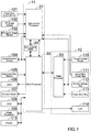
- FIG. 1 is a block diagram illustrating an internal configuration of an image processing apparatus according to one embodiment of the present invention.
- the image processing apparatus is essentially provided with: a processor 11; an operation panel 12; a front door event sensor 101; a DF event sensor 102; a 20-degree angle sensor 103; an authentication device 104; a document size sensor 105; a lamp 106; a scanner motor 107; a CCD 108; an image processor 109; and a printer 115.
- the front door event sensor 101 is a sensor that senses the opening and closing of the front door of the image processing apparatus, and is comprised of a photosensor.
- the signal is off (level H) when the front door is open, and the signal is on (level L) when the front door is closed.
- the supply of power to the internal motor mechanism is cut off for the sake of user safety.
- This configuration allows the user to select a period of time for which the front door can be left open according to his/her preference such that, in case of an error to the motor mechanism which is controlled by the firmware (FW), the user will be able to reset the state manually.
- the front door is equipped with a magnetic closure for the resistance to repeated opening and closing. Although the magnetic closure can hold the front door properly closed when the user opens and closes it slowly enough, it can fail when the user opens and closes it quickly. So, this configuration needs to have a mechanism to eliminate chattering.
- the DF event sensor 102 is a sensor that senses the opening and closing of an automatic document feeder (to be also referred to as DF for short) 31 as illustrated in FIGs. 5 and 6 , and is comprised of a magnetic sensor.
- the DF 31 is a combination of a document cover for fixing a document on the platen and a document conveyor that conveys a document mechanically.
- the signal is off (level H) when the DF 31 is open, and the signal is on (level L) when the DF 31 is closed.
- the 20-degree angle sensor 103 is a sensor that senses the angle of the DF 31 when the user opens the DF 31, and is comprised of a photosensor.
- the signal is off (level H).
- the signal is on (level L) and the size of a document thus can be sensed.
- the authentication device 104 performs user authentication using a wireless IC card and responds to a request from the processor 11. During the transition of a main processor 22 from sleep to normal operation, the authentication device 104 performs authentication as instructed by the subordinate processor 21.
- the authentication device 104 may be comprised of an external apparatus.
- the document size sensor 105 is comprised of a photo-reflective sensor, and senses the presence or absence of reflected light from a document By judging the presence or absence of a document in sub-scanning (FD) lines, the document size sensor 105 senses the sub-scanning (FD) dimension of the document.
- FD sub-scanning
- the lamp 106 is disposed on a slider 51 (shown in FIG. 6 ), and turns on its LED light source in sync with the image scanning of the CCD 108.
- the scanner motor 107 runs the slider 51 to a position determined by the number of pulses.
- the CCD 108 is comprised of a color linear sensor, and receives reflected light from a document to convert to image data.
- the image processor 109 applies correction to the image data obtained by the CCD 108 to fit it to the purpose.
- the printer 115 prints the following data on paper: image data obtained by the CCD 108 then subjected to correction by the image processor 109; print data received externally; and fax data received externally.
- the processor 11 is provided with the subordinate processor 21; the main processor 22; and a non-volatile RAM 24.
- the subordinate processor 21 controls the image processing apparatus basically while the main processor 22 is not in normal operation mode. Specifically, the subordinate processor 21 receives user events and inputs to the image processing apparatus and control power supply.
- the subordinate processor 21 is an always-on processor, being allowed to receive power supply even while sleep mode is on.
- the main processor 22 controls the image processing apparatus in a unified and systematic manner, it is turned off without power supply while sleep mode is on.
- sleep mode When sleep mode is terminated, the main processor 22 restores power supply and starts the initialization; upon completing the initialization, the main processor 22 resumes normal operation.
- the main processor 22 further performs different operations depending on the event having been sensed by the subordinate processor 22 during the transition from sleep to normal operation, as to be described later.
- the non-volatile RAM 24 is a memory that stores records of the input events having been received by the subordinate processor 21 during the transition of the main processor 22 from sleep to normal operation.
- the non-volatile RAM 24 can be accessed both from the subordinate processor 21 and the main processor 22.
- the non-volatile RAM 24 may be an always-on RAM.
- the operation panel 12 is provided with: a panel processor 23; a touch-screen panel 110; a secondary power key 111; a screen display key 112; a copy start key 113; and an LCD 114.
- the touch-screen panel 110 senses a touch event on the touch-screen panel itself by sensing a change in electrostatic capacity.
- the secondary power key 111 can be pressed by the user giving instructions to switch the mode to sleep and to normal operation.
- the screen display key 112 is a hardware key for the user to give an instruction to show a screen registered in advance.
- the signal is on (level L) when the key is pressed, and the signal is off (level H) when the key is unpressed. To prevent an accidental touch by the user and eliminate chattering, the signal should be on under the condition that the key is being pressed for more than a certain period.
- Each screen registered in advance may be associated with a user.
- the copy start key 113 is a key for the user to initiate a copy job created by the user.
- the LCD 114 is a liquid-crystal display that shows operation screens.
- FIG. 2 is a block diagram illustrating an internal configuration of the subordinate processor 21.
- the subordinate processor 21 is provided with: a data bus 121a; a ROM 122a; a subordinate CPU 124a; a timer 127; an input portion 125a; a power supply controller 128; a data transmitter-receiver 126a; and a fax transmitter-receiver 129a.
- FIG. 3 is a block diagram illustrating an internal configuration of the main processor 22.
- the main processor 22 is provided with: a data bus 121b; a ROM 122b; a main CPU 124b; a graphic display controller (GDC) 133; an input portion 125b; an output portion 131; a document size sensor 132; a data transmitter-receiver 126b; and a fax transmitter-receiver 129b.
- GDC graphic display controller
- FIG. 4 is a block diagram illustrating an internal configuration of the panel processor 23.
- the panel processor 23 is provided with: a data bus 121c; a ROM 122c; a RAM 123c; a CPU 124c; an input portion 125c; and a data transmitter-receiver 126c.
- the data bus 121a is a bus that allows the CPU 124a to read and write data from and to the ROM 122a and the RAM 123a; referring to FIG. 3 , the data bus 121b is a bus that allows the CPU 124b to read and write data from and to the ROM 122b and the RAM 123b; referring to FIG. 4 , the data bus 121c is a bus that allows the CPU 124c to read and write data from and to the ROM 122c and the RAM 123c.
- the ROM 122a is a memory storing operation programs for the CPU 124a; the ROM 122b is a memory storing operation programs for the CPU 124b; the ROM 122c is a memory storing operation programs for the CPU 124c.
- the RAM 123a serves as a workspace memory for the CPU 124a; the RAM 123b serves as a workspace memory for the CPU 124b; the RAM 123c serves as a workspace memory for the CPU 124c.
- the CPU 124a controls the CPU 21 in a unified and systematic manner; the CPU 124b controls the CPU 22 in a unified and systematic manner; the CPU 124c controls the CPU 23 in a unified and systematic manner.
- the input portions 125a, 125b, and 125c each sense the signals of sensors and keys and retain them for a certain period of time.
- the data transmitter-receivers 126a, 126b, and 126c are connected to each other through a universal asynchronous receiver-transmitter (UART), being allowed to transmit and receive data to and from each other.
- UART universal asynchronous receiver-transmitter
- the data transmitter-receiver 126a of the subordinate processor 21 and the data transmitter-receiver 126b of the main processor 22 each are connected to the non-volatile RAM 24, being allowed to read and write data from and to the non-volatile RAM 24.
- the fax transmitter-receivers 129a and 129b each transmit and receive fax data through a fax line.
- the timer 127 is provided with a timing means. Being given an initial value, the timer 127 starts counting down from the initial value.
- the timer 127 also provides time stamp values.
- the power supply controller 128 turns on and off the main processor 22.
- the output portion 131 turns on and off the lamp 106 and regulates the signal to the scanner motor 107.
- the document size sensor 132 senses the main scanning (CD) dimension of a document with reference to the image data obtained by the CCD 108.
- the GDC 133 reads out screen data to transfer to the operation panel 112 on a periodic basis.
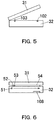
- FIG. 5 is a schematic drawing illustrating the arrangement of sensors that serve for document scanning.
- code 32 indicates a scanner for scanning a document, including a platen the surface of which a document is to be set on.
- FIG. 5 is a side view of the DF 31 and the scanner 32.
- the DF event sensor 102 is positioned on the front side of the scanner 32.
- the 20-degree angle sensor 103 is positioned on the back side of the scanner 32, and is pressed and retracted when the undersurface of the DF 31 is positioned at an angle of 20 degrees or less.
- FIG. 6 is a schematic drawing illustrating the position of a shading reference plate 53.
- the slider 51 and the CCD 108 are positioned inside of the scanner 32; and, furthermore, a one-pass DF platen glass 52, the shading reference plate 53, and the platen glass 54 are positioned between the DF 31 and the scanner 32.
- the home position is fixed on the left of the one-pass DF platen glass 52; the position for document size sensing is fixed on the right of the shading reference plate 53.
- the sub-scanning dimension of a document is sensed by a sensor (not shown in the figure) that senses the presence or absence of a document.
- the main scanning dimension of a document is sensed by the CCD 108.
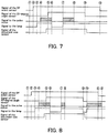
- FIG. 7 is a timing diagram illustrating the document size sensing operation to be performed in the conventional method when sleep mode is terminated.
- Sleep mode is on at the timing of circled number 1; at this timing, the subordinate processor 21 including the subordinate CPU 124a is running but the main processor 22 including the main CPU 124b is not running.
- the user opens the DF 31 at the timing of circled number 2; at this timing, the DF event sensor 102 senses the opening of the DF 31. Being turned on, the main processor 22 starts the initialization at the timing of circled number 3.
- the slider 51 starts running from the home position to the shading reference plate 53.
- the undersurface of the DF 31 is positioned at an angle of 20 degrees or less, permitting the sensing of document size.
- the lamp 106 is turned on and the operation of obtaining reference data from the shading reference plate 53 is started.
- the user sets a document on the platen glass 54 and closes the DF 31 at the timing of circled number 9; at this timing, the 20-degree angle sensor 103 senses the closing of the DF 31.
- the main processor 22 receives signals to sense the sub-scanning dimension of the document.
- the main processor 22 does not sense the main scanning dimension of the document because of not having control of the scanning of the CCD 108.
- the DF 31 is closed properly at the timing of circled number 10.
- the main processor 22 does not receive a notice of the opening of the DF 31. So, even when the user sets a document in position and closes the DF 31, the main processor 22 only fails to sense the document size. Instead, the main processor 22 displays a message stating "document size sensor error" on the operation panel. Seeing this message, the user has to manipulate paper size settings or to open and close the DF 31 again to allow document size sensing in a mechanical manner, which is inconvenient in either case.
- FIG. 8 is a timing diagram illustrating the document size sensing operation to be performed in this embodiment when sleep mode is terminated.
- the user opens the DF 31 at the timing of circled number 2; at this timing, the DF event sensor 102 senses the opening of the DF 31.
- the subordinate processor 21 stores a record indicating the opening of the DF 31 in the non-volatile RAM 24. Being turned on, the main processor 22 starts the initialization at the timing of circled number 3.
- the slider 51 starts running from the home position to the shading reference plate 53.
- the undersurface of the DF 31 is positioned at an angle of 20 degrees or less, permitting the sensing of document size.
- the main processor 22 receives a notice from the subordinate processor 21 and obtains the record of the opening of the DF 31 from the non-volatile RAM 24.
- the user sets a document on the platen glass 54 and closes the DF 31 at the timing of circled number 9; at this timing, the 20-degree angle sensor 103 senses the closing of the DF 31 and transfer a notice to the main processor 22.
- the main processor 22 receives the notice, the main processor 22, as if the event had occurred in normal operation mode, turns on the lamp 106 and senses the signal of the linear sensor by running the CCD 108.
- the lamp 106 is turned off and the slider 51 starts running back to the home position.
- the DF 31 is closed properly at the timing of circled number 11.
- the operation panel 12 displays a message stating "copy service available”.
- the main processor 22 after the transition from sleep to normal operation, the main processor 22 obtains a record indicating the opening of the DF 31 from the non-volatile RAM 24 and performs processing using it.
- the main processor 22 is thus allowed to sense the document size as if the event had occurred in normal operation mode. So, the user does not have to manipulate paper size settings or open and close the DF 31 again.
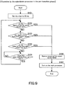
- FIG. 9 is a flowchart representing the operation to be performed by the subordinate processor 21 before the transition from sleep to normal operation.
- the signals of the front door event sensor 101 and the DF event sensor 102 change to on to keep the mode sleep, and the signal of the secondary power key 111 changes to off to keep the mode sleep.
- the timer 127 is set to 20 ms as an initial value (Step S101). The timer 127 then starts counting down by itself.
- Step S102 it is judged whether or not the signal of the DF event sensor 102 is off, by inquiring of the input portion 125a. If it is off (YES in Step S102), this means that the signal changed from on to off; more specifically, the user opened the DF 31 to allow the apparatus to resume from sleep mode. Thus a record of the event is added to an event log table stored on the non-volatile RAM 24 (Step S106) and the main processor 22 is turned on (Step S107). Then the flowchart terminates. If it is on (NO in Step S102), this means that the signal did not change, and it is further judged whether or not the signal of the front door event sensor 101 is off, by inquiring of the input portion 125a (Step S103).
- Step S103 If it is off (YES in Step S103), this means that the signal changed from on to off; more specifically, the user opened the front door to allow the apparatus to resume from sleep mode. This change is recorded in the event log table stored on the non-volatile RAM 24 (Step S106). If it is on (NO in Step S103), this means that the signal did not change, and it is further judged whether or not the signal of the secondary power key 111 is on, by inquiring of the input portion 125a (Step S104).
- Step S104 if the signal of the secondary power key 111 is on (YES in Step S103), this means that the signal changed from off to on; more specifically, the user pressed the secondary power key 111 to allow the apparatus to resume from sleep mode. This change is recorded in the event log table stored on the non-volatile RAM 24 (Step S106). If it is off (NO in Step S104), this means that the signal did not change, and it is further judged whether or not the timer 127 indicates 0 ms or less (Step S105).
- Step S105 If it indicates 0 ms or less (YES in Step S105), this means that a monitoring period of 20 ms has elapsed, and the flowchart returns to Step S102 to wait for another event. If it indicates greater than 0 ms (NO in Step S105), the flowchart waits until it indicates 0 ms or less.
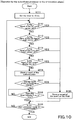
- FIG. 10 is a flowchart representing the operation to be performed by the subordinate processor 21 during the transition from sleep to normal operation.
- the timer 127 is set to 10 ms, a value less than that in the operation performed before the transition from sleep to normal operation, as an initial value (Step S111). The timer 127 then starts counting down by itself. By setting the timer 127 to a value less than that in the operation performed before the transition from sleep to normal operation, as an initial value, the subordinate processor 21 can sense an event on the image processing apparatus quickly during the transition of the main CPU 124b from sleep to normal operation.
- Step S112 it is judged whether or not the signal of the DF event sensor 102 is off, by inquiring of the input portion 125a. If it is off (YES in Step S112), a record of the event is added to the event log table stored on the non-volatile RAM 24 (Step S120). Then the flowchart proceeds to Step S119.
- Step S113 If it is on (NO in Step S112), it is further judged whether or not the signal of the 20-degree angle sensor 103 is off, by inquiring of the input portion 125a (Step S113). If it is off (YES in Step S113), a record of the event is added to the event log table stored on the non-volatile RAM 24 (Step S120). Then the flowchart proceeds to Step S119. If it is on (NO in Step S113), it is further judged whether or not the signal of the front door event sensor 101 is off, by inquiring of the input portion 125a (Step S114).
- Step S114 If it is on (YES in Step S114), a record of the event is added to the event log table stored on the non-volatile RAM 24 (Step S120). Then the flowchart proceeds to Step S119. If it is on (NO in Step S114), it is further judged whether or not the signal of the screen display key 112 is on, by inquiring of the input portion 125a (Step S115).
- Step S115 If the signal of the screen display key 112 is on (YES in Step S115), a record of the event is added to the event log table stored on the non-volatile RAM 24 (Step S120). Then the flowchart proceeds to Step S119. If it is off (NO in Step S115), a request for a result of the authentication using an IC card, for example, is transmitted to the authentication device 104 and it is received in response (Step S116). Here, if the authentication was successful, an ID code is also received. It is further judged whether or not the result of the authentication changed, by inquiring of the data transmitter-receiver 126a (Step S117).
- Step S117 If the result of the authentication changed (YES in Step S117), a record of the event is added to the event log table stored on the non-volatile RAM 24 (Step S120). Then the flowchart proceeds to Step S119. If the result of the authentication did not change (NO in Step S117), it is further judged whether or not the timer 127 indicates 0 ms or less (Step S118). If it indicates greater than 0 ms (NO in Step S118), the flowchart waits until it indicates 0 ms or less. If it indicates 0 ms or less (YES in Step S118), this means that a monitoring period of 10 ms has elapsed, and the flowchart proceeds to Step S119.
- Step S119 it is judged whether or not the main processor 22 is ready to communicate. If it is not ready to communicate (NO in Step S119), the flowchart returns to Step S112 to judge the signal of the sensor. If it is ready to communicate (YES in Step S119), the flowchart terminates.
- FIG. 11 is a flowchart representing the operation to be performed by the subordinate processor 21 after the transition from sleep to normal operation.
- the timer 127 is set to 10 ms, a value less than that in the operation performed before the transition from sleep to normal operation, as an initial value (Step S131). The timer 127 then starts counting down by itself.
- Step S132 it is judged whether or not the signal of the DF event sensor 102 is off, by inquiring of the input portion 125a. If it is off (YES in Step S132), a record of the event is not added to the event log table stored on the non-volatile RAM 24 but a notice is transferred to the main processor 22 (Step S137). Then it is judged whether or not it started to enter sleep mode (Step S136).
- Step S136 If it started to enter sleep mode (YES in Step S136), the flowchart terminates. If it did not start to enter sleep mode (NO in Step S136), the flowchart returns to Step S132.
- Step S133 If the signal of the DF event sensor 102 is on (NO in Step S132), it is further judged whether or not the signal of the 20-degree angle sensor 103 is off, by inquiring of the input portion 125a (Step S133).
- Step S133 If it is off (YES in Step S133), a notice of the event is transmitted to the main processor 22 (Step S137). If it is on (NO in Step S133), it is further judged whether or not the signal of the front door event sensor 101 is off, by inquiring of the input portion 125a (Step S134).
- Step S134 If it is off (YES in Step S134), a notice of the event is transmitted to the main processor 22 (Step S137). If it is on (NO in Step S134), it is further judged whether or not the timer 127 indicates 0 ms or less (Step S135).
- Step S135 If it indicates 0 ms or less (YES in Step S135), this means that a monitoring period of 10 ms has elapsed. Then it is judged whether or not to the subordinate processor 21 should enter sleep mode (Step S136). If it indicates greater than 0 ms (NO in Step S135), the flowchart waits until it indicates 0 ms or less.
- the main CPU 124b of the main processor 22 Upon completing the initialization, the main CPU 124b of the main processor 22 is ready to operate as normal. So, the subordinate processor 21 does not store records relating to the DF event sensor 102 and other sensors and keys on the non-volatile RAM 24 but only transfers notices to the main processor 22.
- the main processor 22 may judge the signals of the sensors and keys (events).
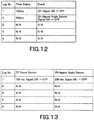
- FIG. 12 is an example of an event log table stored on the non-volatile RAM 24.
- the table is composed of the columns titled "Log No.”, "Time Stamp", and "Event”. All records are deleted from the table when a notice is transferred to the main processor 22; and new records are added to the table in chronological order during the transition from sleep to normal operation. Time stamps values, provided by the timer 127, are elapsed times.
- FIG. 13 is another example of the event log table shown in FIG. 12 , containing a set of records classified by sensor.
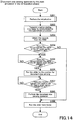
- FIG. 14 is a flowchart representing the document size sensing operation to be performed by the main processor 22 during the transition from sleep to normal operation.
- the main processor 22 starts the initialization upon being turned on by the subordinate processor 21, and obtains shading reference data (Step S201).
- Step S202 a notice stating that it is ready to communicate is transmitted to the subordinate processor 21; and all the records in the event log table are retrieved from the non-volatile RAM 24 (Step S203).
- Step S204 it is judged whether or not any of the records indicates that the signal of the DF event sensor 102 changed to off. If there is no such record (NO in Step S204), this means that the user did not open the DF 31 and there is no need for document size sensing. The slider 51 runs back to the home position to get ready for another scan (Step S209) and the flowchart terminates. If any of the records indicates that the signal of the DF event sensor 102 changed to off (YES in Step S204), this means that the user opened the DF 31, and it is further judged whether or not any of the records indicates that the signal of the 20-degree angle sensor 103 changed to off (Step S205).
- Step S205 If there is no record indicating that the signal of the 20-degree angle sensor 103 changed to off (NO in Step S205), the flowchart waits until such a signal is received. If any of the records indicates that the signal of the 20-degree angle sensor 103 changed to off (YES in Step S205), the slider 51 runs from the position for the shading reference plate 53 to the position for document size sensing (Step S206). It is further judged whether or not any of the records indicates that the signal of the 20-degree angle sensor 103 changed to on (Step S207).
- Step S207 If there is no record indicating that the signal of the 20-degree angle sensor 103 changed to on (NO in Step S207), the flowchart waits until such a signal is received. If any of the records indicates that the signal of the 20-degree angle sensor 103 changed to on (YES in Step S207), the document size sensing operation is performed (Step S208). The slider 51 runs back to the home position (Step S209) and the flowchart terminates.
- FIG. 15 is a flowchart representing the document size sensing operation to be performed by the main processor 22 after the transition from sleep to normal operation.
- Step S231 it is judged whether or not any of the records indicates that the signal of the DF event sensor 102 changed to off. If there is no such record (NO in Step S231), the flowchart waits until it is retrieved. If there is such a record (YES in Step S231), this means that the user opened the DF 31, and it is further judged whether or not any of the records indicates that the signal of the 20-degree angle sensor 103 changed to off (Step S205).
- the following steps of this flowchart with the step numbers, Steps S206 to S209, are the same as Steps S206 to S209 of the flowchart shown in FIG. 14 , representing the document size sensing operation to be performed during the transition from sleep to normal operation; so, these steps will not be described again.
- FIG. 16 is a flowchart representing a subroutine that corresponds to the initialization operation, Step S201 from the flowchart shown in FIG. 14 .
- the slider 51 runs back to the home position that is the base position in Step S212, and then runs to the position for the shading reference plate 53 (Step S213).
- Step S214 the lamp 106 is turned on, the CCD 108 scans the shading reference plate 53, and shading correction values are created. Then the subroutine terminates.
- FIG. 17 is a flowchart representing a subroutine that corresponds to the document size sensing operation, Step S208 from the flowchart shown in FIG. 15 .
- Step S221 the lamp 106 is turned on, the CCD 108 scans a document, and the document size sensor 132 senses the CD dimension (main scanning dimension) of the document.
- Step S222 the document size sensor 105 senses the FD dimension (sub-scanning dimension) of the document.
- Step S223 a standard paper size most suitable for the CD and FD dimension of the document is selected.
- a long period of time may have elapsed since a notice stating that the signal of the 20-degree angle sensor 103 is on is received, which can cause a sensor error and result in either the CD or FD dimension being successfully obtained.
- more than one standard paper size most suitable for the either dimension can be selected.
- Step S224 the LCD 114 shows the one or more than one paper size selected in the previous step. Then the subroutine terminates.
- FIG. 18 is a flowchart representing the status reset operation to be performed by the main processor 22.
- Step S301 a notice stating that it is ready to communicate is transmitted to the subordinate processor 21; and all the records in the event log table are retrieved from the non-volatile RAM 24 (Step S302).
- Step S303 it is judged whether or not any of the records indicates that the signal of the front door event sensor 101 changed to off. If there is no such record (NO in Step S303), the flowchart waits until it is retrieved. If there is such a record (YES in Step S303), this means that the user opened the front door, and it is further judged whether or not any of the records indicates that the signal of the front door event sensor 101 changed to on (Step S304).
- Step S304 If there is no record indicating that the signal of the front door event sensor 101 changed to on (NO in Step S304), the flowchart waits until such a signal is received. If any of the records indicates that the signal of the front door event sensor 101 changed to on (YES in Step S304), this means that the user closed the front door, and it is further judged whether or not the signal of the front door event sensor 101 had been off for a period of 0.5 to 2 sec. by checking the time stamp (Step S305). Here, the temporal condition for the judgment is the same as that in normal operation mode.
- Step S305 if the signal had been off for a period of 0.5 to 2 sec. (YES in Step S305), this means that the user encountered an error and is manipulating to reset the status. After the status is reset (Step S306), the flowchart returns to Step S303.
- Step S305 if the signal had been off for a period of more than 2 sec. (NO in Step S305), this means that the user opened the front door for maintenance purposes.
- Step S305 if the signal had been off for a period of less than 0.5 sec. (NO in Step S305), this means that the chattering of the magnetic closure occurred. In either case, the flowchart immediately returns to Step S303.
- FIG. 19 is a flowchart representing the screen display operation to be performed by the main processor 22.
- Step S401 a notice stating that it is ready to communicate is transmitted to the subordinate processor 21; and all the records in the event log table are retrieved from the non-volatile RAM 24 (Step S402).
- Step S403 the main processor 22 starts communication with the panel processor 23 to activate.
- Step S404 it is judged whether or not any of the records indicates that the signal of the screen display key 112 changed to on. If there is no record indicating that the signal of the screen display key 112 changed to on (NO in Step S404), this means that the user did not press the screen display key 112, and the flowchart immediately terminates. If there is such a record (YES in Step S404), this means that the user pressed the screen display key 112, and it is further judged whether or not any of the records indicates that the signal of the screen display key 112 changed to off (Step S405).
- Step S405 If there is no record indicating that the signal of the screen display key 112 is off (NO in Step S405), the flowchart waits until such a signal is received. If there is a record indicating that the signal of the screen display key 112 changed to off (YES in Step S405), it is further judged whether or not the signal of the screen display key 112 had been on for a period of 300 ms or more by checking the time stamp (Step S406). Here, the temporal condition for the judgment is the same as that in normal operation mode.
- Step S406 if the signal had been on for a period of 300 ms or more (YES in Step S406), this means that the user pressed the screen display key 112, and the data transmitter-receiver 126b transmits a notice to the panel processor 23 (Step S407). Then the flowchart terminates. If the signal had been on for a period of less than 300 ms (NO in Step S406), this means that the user accidentally pressed the key, and the flowchart immediately terminates. In normal operation mode, the panel processor 23 senses the pressing of the screen display key 112.
- FIG. 20 is a flowchart representing the authentication operation to be performed by the main processor 22.
- Step S501 a notice stating that it is read to communicate is transmitted to the subordinate processor 21; and all the records in the event log table are retrieved from the non-volatile RAM 24 (Step S502).
- Step S503 it is judged whether or not any of the records indicates authentication success; for reference, FIG. 21 shows an example of the event log table used here. If there is such a record (YES in Step S503), this means that the user has been successfully authenticated using his/her IC card, for example. It is further judged whether or not more than one record indicates authentication success (Step S504). If there is no record indicating authentication success (NO in Step S503), the flowchart immediately terminates.
- Step S504 if only one record indicates authentication success (NO in Step S504), the corresponding ID code is transferred to the authentication device 104 and the credentials are received in response (Step S505). Then the flowchart terminates. If more than one record indicates authentication success (YES in Step S504), the most recently added record in the event log table is searched for by the log number or the time stamp, and the corresponding ID code is obtained (Step S506). Then the flowchart proceeds to Step S505. In normal operation mode, the main processor 22 performs the authentication management.
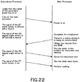
- FIG. 22 is a sequence diagram showing the document size sensing operation to be performed by the subordinate processor 21 and the main processor 22.
- the subordinate processor 21 turns on the main processor 22 to terminate sleep mode. Being turned on, the main processor 22 starts the initialization. Judging that the signal of the DF event sensor 102 or the 20-degree angle sensor 103 is off, the subordinate processor 21 adds a record in the event log table stored on the non-volatile RAM 24.
- the main processor 22 transmits a notice stating that it is ready to communicate to the subordinate processor 21. Then the main processor 22 retrieves all the records in the event log table from the non-volatile RAM 24 and runs the slider 51 to the position for document size sensing.
- the subordinate processor 21 transmits a notice to the main processor 22; and the main processor 22 senses the document size and runs the slider 51 back to the home position. Judging that the signal of the DF event sensor 102 is on, the subordinate processor 21 transmits a notice to the main processor 22; but the main processor 22 does not perform anything.
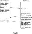
- FIG. 23 is a sequence diagram showing the status reset operation to be performed by the subordinate processor 21 and the main processor 22.
- the subordinate processor 21 turns on the main processor 22 to terminate sleep mode. Being turned on, the main processor 22 starts the initialization. Judging that the signal of the front door event sensor 101 is off, the subordinate processor 21 adds a record in the event log table stored on the non-volatile RAM 24.
- the main processor 22 transmits a notice stating that it is ready to communicate to the subordinate processor 21. Then the main processor 22 retrieves all the records in the event log table from the non-volatile RAM 24 and finds that the signal of the front door sensor 101 is off.
- the subordinate processor 21 Judging that the signal of the front door sensor 101 is on, the subordinate processor 21 transmits a notice to the main processor 22.
- the main processor 22 judges the period of time for which the front door had been left open and performs the status reset operation.
- FIG. 24 is a sequence diagram showing the screen display operation to be performed by the subordinate processor 21 and the main processor 22.
- the subordinate processor 21 turns on the main processor 22 to terminate sleep mode. Being turned on, the main processor 22 starts the initialization. Judging that the signal of the screen display key 112 is on, the subordinate processor 21 adds a record in the event log table stored on the non-volatile RAM 24.
- the main processor 22 transmits a notice stating that it is ready to communicate to the subordinate processor 21. Then the main processor 22 retrieves all the records in the event log table from the non-volatile RAM 24 and finds that the signal of the screen display key 112 is on.
- the subordinate processor 21 Judging that the signal of the screen display key 112 is off, the subordinate processor 21 transmits a notice to the main processor 22.
- the main processor 22 judges the period of time for which the screen display key 112 had been kept pressed and transmits a notice of the pressing of the screen display key 112 to the panel processor 23.
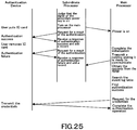
- FIG. 25 is a sequence diagram showing the authentication operation to be performed by the subordinate processor 21, the main processor 22, and the authentication device 104.
- the subordinate processor 21 turns on the main processor 22 to terminate sleep mode. Being turned on, the main processor 22 starts the initialization.
- the authentication device 104 When the user puts his/her IC card, the authentication device 104 performs authentication. Until the main processor 22 completes the initialization, the subordinate processor 21 repeatedly transmits a request for a result of the authentication to the authentication device 104. If the authentication was successful, the subordinate processor 21 receives a response indicating authentication success. When the user withdraws his/her IC card, the authentication device 104 does not perform authentication, and the subordinate processor 21 receives a response indicating authentication failure. Every time it receives a response indicating authentication success or failure, the subordinate processor 21 adds a record in the event log table stored on the non-volatile RAM 24.
- the main processor 22 transmits a notice stating that it is ready to communicate to the subordinate processor 21. Then the main processor 22 retrieves all the records in the event log table from the non-volatile RAM 24 and searches for any record indicating authentication success. If there is such a record, the main processor 22 obtains the user's credentials from the authentication device 104. The authentication operation is thus completed.
- FIG. 26 is a flowchart representing the table access control operation to be performed by the subordinate processor 21.
- Step S601 any records of an event on the 20-degree angle sensor 103 and a result of the authentication are permitted to be added to the event log table stored on the non-volatile RAM 24.
- Step S602 Since the screen display key 112 serves to retrieve a screen associated with the user, the user must be successfully authenticated for the sake of security. In Step S602, unless the user is successfully authenticated, any record of an event on the screen display key 112 is prohibited from being added to the table. That means, the access to the event log table is prohibited in regard to the key.
- Step S603 it is judged whether or not a response indicating authentication success is received. If it is not on (NO in Step S603), the flowchart waits until it is received. If it is received (YES in Step S603), this means that the user is successfully authenticated, and any record of an event on the screen display key 112 is permitted to be added to the table in Step S604.
- the successfully authenticated user may manipulate again for the authentication, but a record indicating authentication success or failure will not be stored on the non-volatile RAM 24. This will take a load off the subordinate processor 21 and keep as much free space as possible in the non-volatile RAM 24 without duplicate information.
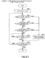
- FIG. 27 is a flowchart representing another example of the operation to be performed by the subordinate processor 21 during the transition from sleep to normal operation.
- the timer 127 is set to 10 ms, a value less than that in the operation performed before the transition from sleep to normal operation, as an initial value (Step S611). The timer 127 then starts counting down by itself.
- Step S612 it is judged whether or not the signal of the copy start key 113 is on, by inquiring of the input portion 125a. If it is on (YES in Step S612), a record of the event is added to the event log table stored on the non-volatile RAM 24 (Step S617). Then the flowchart proceeds to Step S616.
- Step S613 If it is off (NO in Step S612), it is further judged whether or not the signal of the 20-degree angle sensor 103 is off, by inquiring of the input portion 125a (Step S613). If it is off (YES in Step S613), a record of the event is added to the event log table stored on the non-volatile RAM 24 (Step S617). Then the flowchart proceeds to Step S614. If it is on (NO in Step S613), it is further judged whether or not the signal of the DF event sensor 102 is off, by inquiring of the input portion 125a (Step S614).
- Step S614 If it is off (YES in Step S614), a record of the event is added to the event log table stored on the non-volatile RAM 24 (Step S617). Then the flowchart proceeds to Step S616. If it is on (NO in Step S614), it is further judged whether or not the timer 127 indicates 0 ms or less (Step S615). If it indicates greater than 0 ms (NO in Step S615), the flowchart waits until it indicates 0 ms or less. If it indicates 0 ms or less (YES in Step S615), this means that a monitoring period of 10 ms has elapsed, and the flowchart proceeds to Step S616.
- Step S616 it is judged whether or not the main processor 22 is ready to communicate. If it is not ready to communicate (NO in Step S616), the flowchart returns to Step S612 to judge the signal of the copy start key 113. If it is ready to communicate (YES in Step S616), the flowchart terminates.
- the main processor 22 is allowed to start copy automatically after the transition from sleep to normal operation, as to be described later. So, the user does not have to press the copy start key 113 again.
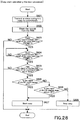
- FIG. 28 is a flowchart representing the copy start operation to be performed by the main processor 22.
- Step S621 a notice stating that it is ready to communicate is transmitted to the subordinate processor 21; and all the records in the event log table are retrieved from the non-volatile RAM 24 (Step S622).
- Step S623 it is judged whether or not any of the records indicates that the signal of the copy start key 113 changed to on. If there is such no record (NO in Step S623), this means that the user did not press the copy start key 113, and the flowchart immediately terminates. If any of the records indicates that the signal of the copy start key 113 changed to on (YES in Step S623), it is further judged whether or not any of the records indicates that the signal of the copy start key 113 changed to off (Step S624).
- Step S624 If there is no record indicating that the signal changed to off (NO in Step S624), the flowchart waits until such a signal is received. If any of the records indicates that the signal changed to off (YES in Step S624), it is further judged in Step S625 whether or not the signal of the copy start key 113 had been on for a period of 300 ms or more by checking the time stamp. If the signal had been on for a period of less than 300 ms (NO in Step S625), this means that the user accidentally pressed the copy start key 113, and the flowchart immediately terminates.
- Step S625 If the signal had been on for a period of 300 ms or more (YES in Step S625), it is further judged whether or not the signal of the DF event sensor 102 is on (Step S626). If it is on (YES in Step S626), the copy operation starts in Step S627. If it is off (NO in Step S626), it is further judged in Step S628 whether or not the signal of the 20-degree angle sensor 103 is off.
- Step S628 If it is off (YES in Step S628), the copy operation starts in Step S627. If it is on (NO in Step S628), the copy operation stops in Step S629. If the signal of the DF open-close sensor 102 is on (changes from off to on), this means that the document has been left on the DF 31 possibly since before the main processor 22 resumed from sleep mode, and the copy operation stops for the sake of security. Similarly, if the signal of the 20-degree angle sensor 103 is not on (changes from off to on), this means that the document has been left on the platen glass possibly since before the main processor 22 resumed from sleep mode, and the copy operation stops for the sake of security.
- FIG. 29 is a flowchart representing yet another example of the operation to be performed by the subordinate processor 21 during the transition from sleep to normal operation.
- the timer 127 is set to 10 ms, a value less than that in the operation performed before the transition from sleep to normal operation, as an initial value (Step S631). The timer 127 then starts counting down by itself.
- Step S632 it is judged whether or not print data is received, by inquiring of the data transmitter-receiver 126a. If print data is received (YES in Step S632), a response is transmitted through the LAN by the subordinate processor 21 acting as a proxy in Step S639. The connection is established and a transfer rate is determined in Step S640; and a record of the event is added to the event log table stored on the non-volatile RAM 24 in Step S638. Then the flowchart proceeds to Step S637.
- Step S632 if print data is not received (NO in Step S632), it is further judged whether or not fax data is received, by inquiring of the fax transmitter-receiver 129a (Step S613). If fax data is received (YES in Step S633), a response is transmitted through the fax line by the subordinate processor 21 acting as a proxy in Step S635. The connection is established and a transfer rate is determined in Step S636; and a record of the event is added to the event log table stored on the non-volatile RAM 24 in Step S638. Then the flowchart proceeds to Step S637.
- Step S633 if fax data is not received (NO in Step S633), it is further judged whether or not the timer 127 indicates 0 ms or less (Step S634). If it indicates greater than 0 ms (NO in Step S634), the flowchart waits until it indicates 0 ms or less. If it indicates 0 ms or less (YES in Step S634), this means that a monitoring period of 10 ms has elapsed, and the flowchart proceeds to Step S637.
- Step S637 it is judged whether or not the main processor 22 is ready to communicate. If it is not ready to communicate (NO in Step S637), the flowchart returns to Step S632 to wait for print data to be received. If it is ready to communicate (YES in Step S637), the flowchart terminates.
- FIG. 30 is a flowchart representing the print data receiving operation to be performed by the main processor 22.
- Step S651 a notice stating that it is ready to communicate is transmitted to the subordinate processor 21; and all the records in the event log table are retrieved from the non-volatile RAM 24 (Step S652).
- Step S653 it is judged whether or not any of the records indicates that print data has been received. If there is no such record (NO in Step S653), the flowchart terminates. If any of the records indicates that print data has been received (YES in Step S653), information about the communications protocol, including the transfer rate, is obtained from the subordinate processor 21 in Step S654. In Step S655, print data is received through the LAN and written into the RAM 123b.
- the user may transmit print data from an external apparatus to the image processing apparatus during the transition of the main processor 22 from sleep to normal operation; even in this case, the image processing apparatus is allowed to obtain the print data and print automatically. So, the user does not have to transmit the print data again.
- FIG. 31 is a flowchart representing the fax data receiving operation to be performed by the main processor 22.
- Step S661 a notice stating that it is ready to communicate is transmitted to the subordinate processor 21; and all the records in the event log table are retrieved from the non-volatile RAM 24 (Step S662).
- Step S663 it is judged whether or not any of the records indicates that fax data has been received. If there is no such record (NO in Step S663), the flowchart terminates. If any of the records indicates that fax data has been received (YES in Step S663), information about the communications protocol, including the transfer rate, is obtained from the subordinate processor 21 in Step S664. In Step S665, fax data is received through the fax line and written into the RAM 123b.
- the user may transmit fax data to the image processing apparatus through the fax line during the transition of the main processor 22 from sleep to normal operation; even in this case, the image processing apparatus is allowed to obtain the fax data and print automatically. So, the user does not have to transmit the fax data again.
- the subordinate processor 21 judges whether or not an event occurs on the image processing apparatus, by inquiring of the front door event sensor 101, the DF event sensor 102, the 20-degree angle sensor 103, the screen display key 112, the copy start key 113, and other sensing means, at predetermined intervals during the transition of the main processor 22 (the main CPU 124b) from sleep to normal operation. If an event occurs, the subordinate processor 21 further stores a record of the event on the non-volatile RAM 24. After the transition, the main processor 22 retrieves the record from the non-volatile RAM 24 and performs processing using it. The main processor 22 is thus allowed to behave as if the event had occurred in normal operation mode. So, the user does not have to manipulate again. By reacting to the user's desire in a mechanical manner as described above, the image processing apparatus has enhanced the convenience.
Landscapes
- Engineering & Computer Science (AREA)
- Theoretical Computer Science (AREA)
- Physics & Mathematics (AREA)
- General Physics & Mathematics (AREA)
- Multimedia (AREA)
- Signal Processing (AREA)
- General Engineering & Computer Science (AREA)
- Human Computer Interaction (AREA)
- Computer Security & Cryptography (AREA)
- Computer Hardware Design (AREA)
- Software Systems (AREA)
- Microelectronics & Electronic Packaging (AREA)
- Facsimiles In General (AREA)
- Control Or Security For Electrophotography (AREA)
- Accessory Devices And Overall Control Thereof (AREA)
Abstract
Description
- The present invention relates to: an image processing apparatus provided with a main CPU to lose power supply while sleep mode is on and a subordinate CPU to receive power supply even while sleep mode is on; and a recording medium storing a program to make the image processing apparatus to resume from sleep mode.
- In recent years, it is not unusual for an image processing apparatus such as a multifunctional digital image forming apparatus having various function such as copier function, printer function, and facsimile function, as referred to as a multifunction peripheral (MFP), to enter sleep mode without any event for a certain period of time. While the reduction of power consumption has been an issue of paramount importance, the transition period from sleep to standby has been a concern left unconsidered.
- Most image processing apparatuses today are configured to enter sleep mode without any event for a certain period of time, and further required to resume from sleep mode as quickly as it enters sleep mode.
- There is a practical method for achieving low power consumption in sleep mode without sacrificing performance in normal operation mode, requiring a subordinate CPU that consumes a small amount of power but runs slowly for continuous signal monitoring and a main CPU that consumes a large amount of power but runs fast. The subordinate CPU turns on and off the main CPU to switch the mode between normal operation and sleep. Being turned on, the main CPU starts the initialization. In this method, during the transition from sleep to normal operation, the main CPU does not run as fast as desired because initializing the values on the main CPU itself and its own external memory and modules still causes a high load on the main CPU.
- This means, the main CPU is not allowed to judge whether or not an event occurs on the image processing apparatus, during the transition from sleep to normal operation. This method has an unsolved problem as described below.
- For example, the user may open the document cover while sleep mode is on, and set a document in position to make a copy. In this case, a sensing means senses the opening of the document cover and sleep mode is terminated. In this method, however, the main CPU is not allowed to judge whether or not the document cover is open during the transition from sleep to normal operation. Instead, the main CPU displays a message stating "document size sensing error" on the operation panel. Seeing this message, the user has to manipulate paper size settings or to open and close the document cover again to make a sensing means sense the document size in a mechanical manner, which is inconvenient in either case.
- The operation panel of the image processing apparatus may have a screen display key for displaying a registered screen on the operation panel, which is a hardware key. In this case, a sensing means senses the pressing of the screen display key if the screen display key is kept pressed for a certain period of time or more. In this method, however, the main CPU is not allowed to judge whether or not the screen display key is pressed during the transition from sleep to normal operation. The main CPU fails to sense the pressing of the screen display key during the transition; and the screen display key will not be kept pressed for a certain period of time or more, resulting in that the same screen, a default screen, being continuously displayed on the operation panel. To display a registered screen, the user has to press the screen display key again, which is still inconvenient.
- To solve the inconvenience, the temporal conditions for sensing the pressing of the key may be different between the pre-transition and in-transition phase. In this case, the user needs to keep the difference in mind when manipulating, which is not user-friendly.
- The image processing apparatus may be configured to make an external authentication device perform authentication on the user using a wireless IC card that records user information, for example. In this case, the external authentication device performs authentication at a predetermined timing, and the image processing apparatus judges whether or not the user is successfully authenticated by inquiring of the authentication device at certain intervals. It is known that, for the sake of security, an IC card should better be withdrawn from the card reading device immediately after the authentication.
- In this method, however, the main CPU is not allowed to judge whether or not the user is successfully authenticated during the transition from sleep to normal operation. The main CPU fails to sense the success of the authentication during the transition, and even can fail after the transition if the user has withdrawn his/her IC card from the card reading device. Instead, the main CPU displays a message stating "please put your IC card" on the operation panel. Seeing this message, the user has to put his/her IC card close to the card reading device again for the authentication, which is inconvenient.
- As described above, in the conventional method, the main CPU is not allowed to judge whether or not an event occurs on the image processing apparatus, during the transition from sleep to normal operation, which is inconvenient and not user-friendly.
- Japanese Unexamined Patent Application Publication No.
2011-059414 - Japanese Unexamined Patent Application Publication No.
H10-257256 - Japanese Unexamined Patent Application Publication No.
2012-142821 - However, the techniques disclosed in Japanese Unexamined Patent Application Publications No.
2011-059414 H10-257256 2012-142821 - The present invention, which has been made in consideration of such a technical background as described above, provides: an image processing apparatus having enhanced the convenience by obtaining a record of an event having occurred during the transition of the main CPU from sleep to normal operation and performing processing using it; and a recording medium.
- The above-described problem can be solved by the following means.
- [1] An image processing apparatus including:
- one or more than one sensing means that senses an event on the image processing apparatus;
- a first memory means;
- a main CPU that loses power supply while sleep mode is on; and
- a subordinate CPU that receives power supply even while sleep mode is on,
- the subordinate CPU performs: terminating sleep mode; judging whether not an event occurs on the image processing apparatus by inquiring of the one or more than one sensing means, at predetermined intervals during the transition of the main CPU from sleep to normal operation; and storing a record of an event on the first memory means if it occurs; and
- after the transition, the main CPU retrieves the record from the first memory means and performs processing using it.
- [2] The image processing apparatus according to the foregoing item [1], wherein after sleep mode is terminated, the subordinate CPU makes the judgment at the predetermined intervals during the transition, the predetermined intervals being shorter than those in sleep mode.
- [3] The image processing apparatus according to the foregoing item [1] or[2], further including:
- a document cover event sensing means that senses the opening and closing of a document cover for covering a platen, the document cover event sensing means serving as the one or more than one sensing means;
- a first document size sensing means that senses the main scanning dimension of a document set on the platen, by inquiring of a document reading means that reads the document; and
- a second document size sensing means that senses the sub-scanning dimension of the document,
- the subordinate CPU stores a record on the first memory means, the record indicating an event sensed by the document cover event sensing means, the event being the opening and closing of the document cover; and
- after the transition, the main CPU performs: retrieving the record from the first memory means, the record indicating the opening and closing of the document cover; and judging the size of the document with reference to the main scanning and sub-scanning dimension having being sensed by the first and second document size sensing means while the transition of the main CPU to normal operating mode.
- [4] The image processing apparatus according to any one of the foregoing items [1] to [3], further including a front door event sensing means that senses the opening and closing of a front door of the image processing apparatus, the front door event sensing means serving as the one or more than one sensing means, wherein:
- the subordinate CPU stores a record on the first memory means, the record indicates an event sensed by front door event sensing means, the event being the opening and closing of the front door; and
- after the transition, the main CPU retrieves the record from the first memory means, the record indicating the opening and closing of the front door, and resets the status.
- [5] The image processing apparatus according to any one of the foregoing items [1] to [4], further including:
- an operation panel having a screen display key for displaying a registered screen;
- a screen display key-pressing sensing means that senses the pressing of the screen display key, the screen display key-pressing sensing means serving as the one or more than one sensing means; and
- a panel processor that controls a set of hardware keys including the screen display key of the operation panel as instructed by the main CPU,
- the subordinate CPU stores a record on the first memory means, the record indicating an event sensed by the screen display key-pressing sensing means, the event being the pressing of the screen display key; and
- after the transition, the main CPU retrieves the record from the first memory means, the record indicating the pressing of the screen display key, and transmits a notice to the panel processor.
- [6] The image processing apparatus according any one of the foregoing items [1] to [5], further including an authentication sensing means that senses the success or failure of the authentication provided by an authentication device that performs user authentication, the authentication sensing means serving as the one or more than one sensing means, wherein:
- the subordinate CPU stores a record on the first memory means, the record including user identification information, the record indicating an event sensed by the authentication sensing means, the event being the success of authentication; and
- after the transition, the main CPU retrieves the record from the first memory means, the record indicating the success of authentication, and obtains credentials associated with the user identification information.
- [7] The image processing apparatus according to the foregoing item [6], wherein the authentication device is an external authentication device and performs user authentication as instructed by the subordinate CPU.
- [8] The image processing apparatus according any one of the foregoing items [1] to [7], wherein the subordinate CPU stores the records on the first memory means in chronological order, the records indicating the events being sensed by the one or more than one sensing means.
- [9] The image processing apparatus according to any one of the foregoing items [1] to [8], wherein the subordinate CPU stores the records on the first memory means such that the records are classified by sensing means.
- [10] The image processing apparatus according to any one of the foregoing items [1], [2], [4], [8], and [9], further including:
- a document cover event sensing means that senses the opening and closing of a document cover for covering a platen, the document cover event sensing means serving as the one or more than one sensing means;
- an operation panel having a screen display key for displaying a user-specific registered screen;
- a screen display key-pressing sensing means that senses the pressing of the screen display key, the screen display key-pressing sensing means serving as the one or more than one sensing means; and
- an authentication sensing means that senses the success or failure of the authentication provided by an authentication device that performs user authentication, the authentication sensing means serving as the one or more than one sensing means,
- [11] The image processing apparatus according to any one of the foregoing items [1], [2], [4], and [8] to [10], further including:
- a document cover event sensing means that senses the opening and closing of a document cover for covering a platen, the document cover event sensing means serving as the one or more than one sensing means;
- an operation panel having a screen display key for displaying a user-specific registered screen;
- a screen display key-pressing sensing means that senses the pressing of the screen display key, the screen display key-pressing sensing means serving as the one or more than one sensing means; and
- an authentication sensing means that senses the success or failure of the authentication provided by an authentication device that performs user authentication, the authentication sensing means serving as the one or more than one sensing means,
- [12] The image processing apparatus according to any one of the foregoing items [1] to [11], further including:
- an operation panel having a copy start key;
- a copy start key-pressing sensing means that senses the pressing of the copy start key, the copy start key-pressing sensing means serving as the one or more than one sensing means; and
- a panel processor that controls a set of hardware keys including the copy start key of the operation panel as instructed by the main CPU,
- the subordinate CPU stores a record on the first memory means, the record indicating an event sensed by the copy start key-pressing sensing means, the event being the pressing of the copy start key; and
- after the transition, the main CPU retrieves the record from the first memory means, the record indicating the pressing of the copy start key, and starts copy.
- [13] The image processing apparatus according to the foregoing item [12], further including a document setting sensing means that senses the setting of a document, wherein:
- the subordinate CPU stores a record on the first memory means, the record indicating an event sensed by the document setting sensing means, the event being the setting of a document; and
- after the transition, the main CPU retrieves the record from the first memory means, the record indicating the pressing of the copy start key, but does not start copy unless the main CPU retrieves the record from the first memory means, the record indicating the setting of a document
- [14] The image processing apparatus according to the foregoing item [12], further including a document cover event sensing means that senses the opening and closing of a document cover for covering a platen, the document cover event sensing means serving as the one or more than one sensing means, wherein:
- the subordinate CPU stores a record on the first memory means, the record indicating an event sensed by the document cover event sensing means, the event being the opening and closing of the document cover; and
- after the transition, the main CPU retrieves the record from the first memory means, the record indicating the pressing of the copy start key, but does not start copy unless the main CPU retrieves the record from the first memory means, the record indicating the opening and closing of the document cover.
- [15] The image processing apparatus according to any one of the foregoing items [1] to [14], further including:
- a first secondary responding means that responds to a signal incoming through a network on behalf of the main CPU;
- a first data receiving means that senses print data from the network after the first secondary responding means responds on behalf of the main CPU, the first data receiving means serving as the one or more than one sensing means; and
- a second memory means that stores the print data temporarily,
- the subordinate CPU stores a record on the first memory means, the record indicating an event sensed by the first data receiving means, the event being the receipt of the print data; and
- after the transition, the main CPU retrieves the record from the first memory means, the record indicating the receipt of the print data, and stores the print data on the second memory means.
- [16] The image processing apparatus according to any one of the foregoing items [1] to [14], further including:
- a second secondary responding means that responds a signal incoming through a facsimile line on behalf of the main CPU;
- a second data receiving means that senses facsimile data from the facsimile line after the second secondary responding means responds on behalf of the main CPU, the second data receiving means serving as the one or more than one sensing means; and
- a second memory means that stores the facsimile data temporarily,
- the subordinate CPU stores a record on the first memory means, the record indicating an event sensed by the second data receiving means, the event being the receipt of the facsimile data; and
- after the transition, the main CPU retrieves the record from the first memory means, the record indicating the receipt of the facsimile data, and stores the facsimile data on the second memory means.
- [17] A non-transitory computer-readable recording medium storing a program for an image processing apparatus including:
- one or more than one sensing means that senses an event on the image processing apparatus;
- a first memory means;
- a main CPU that loses power supply while sleep mode is on; and
- a subordinate CPU that receives power supply even while sleep mode is on,
- According to the invention described in the foregoing
item 1, the subordinate CPU performs: terminating sleep mode; judging whether or not an event occurs on the image processing apparatus, at predetermined intervals during the transition of the main CPU from sleep to normal operation; and storing a record of an event on the first memory means if it occurs. After the transition, the main CPU retrieves the record from the first memory means and performs processing using it. The main CPU is thus allowed to behave as if the event had occurred in normal operation mode. So, the user does not have to manipulate again after the transition of the main CPU. By reacting to the user's desire in a mechanical manner as described above, the image processing apparatus has enhanced the convenience. - According to the invention described in the foregoing
item 2, the subordinate CPU makes the judgment at the predetermined intervals shorter than those in sleep mode, during the transition of the main CPU from sleep to normal operation. The main CPU senses an event immediately after the transition. - According to the invention described in the foregoing
item 3, when the user opens and closes the document cover during the transition of the main CPU from sleep to normal operation, the subordinate CPU senses the dimensions of a document. After the transition, the main CPU judges the document size with reference to the dimensions. So, the user does not have to open and close the document cover again. - According to the invention described in the foregoing
item 4, when the user opens and closes the front door during the transition of the main CPU from sleep to normal operation, the status will be reset after the transition of the main CPU. So, the user does not have to open and close the front door again. - According to the invention described in the foregoing
item 5, when the user presses a screen display key for displaying a registered screen during the transition of the main CPU from sleep to normal operation, a notice of the event will be transferred to the panel processor after the transition of the main CPU, and the user's registered screen will be shown. So, the user does not have to press the screen display key again. - According to the invention described in the foregoing
item 6, when the user is successfully authenticated by an authentication device during the transition of the main CPU from sleep to normal operation, the credentials associated with the identification information of the user will be obtained after the transition of the main CPU. So, the user does not have to manipulate for the authentication again. - According to the invention described in the foregoing item 7, the authentication device performs authentication on the user as instructed by the subordinate CPU during the transition of the main CPU from sleep to normal operation.
- According to the invention described in the foregoing
item 8, the subordinate CPU stores the records of the events sensed by the sensing means on the first memory means in chronological order. - According to the invention described in the foregoing
item 9, the subordinate CPU stores the records of the events on the first memory means such that the records are classified by sensing means. - According to the invention described in the foregoing
item 10, an authentication sensing means senses the success of the authentication. Before the success of authentication, when the user opens and closes the document cover during the transition of the main CPU from sleep to normal operation, the subordinate CPU stores a record of the event on the first memory means; after the success of authentication, when the user presses the screen display key during the transition period, the subordinate CPU does not store a record of the event on the first memory means. In other words, any user having not been successfully authenticated will be unable to view the user's registered screen even by pressing the screen display key, which is reasonable. - According to the invention described in the foregoing
item 11, an authentication sensing means senses the success of the authentication. After that, when the user opens and closes the document cover or presses the screen display key during the transition of the main CPU from sleep to normal operation, the subordinate CPU stores a record of the event on the first memory means. The successfully authenticated user may manipulate again for the authentication, but the subordinate CPU will not store a record indicating the success or failure of the authentication on the first memory means. This will take a load off the subordinate CPU and keep as much free space as possible in the first memory means without duplicate information. - According to the invention described in the foregoing
item 12, when the user presses a copy start key during the transition of the main CPU from sleep to normal operation, the copy operation will start after the transition. So, the user does not have to press the copy start key again. - According to the invention described in the foregoing item 13, when the user presses a copy start key without setting a document in position during the transition of the main CPU from sleep to normal operation, the copy operation will stop even after the transition. In this case, the first memory means does not store a record indicating that a document has been set in position.
- According to the invention described in the foregoing item 14, when the user presses a copy start key without closing the document cover during the transition of the main CPU from sleep to normal operation, the copy operation will stop even after the transition. In this case, the first memory means does not store a record indicating that the document cover has been closed.
- According to the invention described in the foregoing item 15, when print data is received during the transition of the main CPU from sleep to normal operation, the print data will be stored on the second memory means after the transition of the main CPU. In this case, there is a record indicating that print data has been received.
- According to the invention described in the foregoing item 16, when fax data is received during the transition of the main CPU from sleep to normal operation, the fax data will be stored on the second memory means after the transition of the main CPU. In this case, there is a record indicating that fax data has been received.
- According to the invention described in the foregoing item 17, the subordinate CPU terminates sleep mode and judges whether or not an event occurs on the image processing apparatus, at predetermined intervals during the transition of the main CPU from sleep to normal operation. If an event occurs, the subordinate CPU further stores a record of the event on the first memory means.
-
-
FIG. 1 is a block diagram illustrating an internal configuration of an image processing apparatus according to one embodiment of the present invention. -
FIG. 2 is a block diagram illustrating an internal configuration of a subordinate processor. -
FIG. 3 is a block diagram illustrating an internal configuration of a main processor. -
FIG. 4 is a block diagram illustrating an internal configuration of a panel processor. -
FIG. 5 is a schematic drawing illustrating the positions of sensors to be used when a document is scanned. -
FIG. 6 is a schematic drawing illustrating the position of a shading reference plate. -
FIG. 7 is a timing diagram illustrating the document size sensing operation to be performed in the conventional method when sleep mode is terminated. -
FIG. 8 is a timing diagram illustrating the document size sensing operation to be performed in this embodiment when sleep mode is terminated. -
FIG. 9 is a flowchart representing the operation to be performed by the subordinate processor before the transition from sleep to normal operation. -
FIG. 10 is a flowchart representing the operation to be performed by the subordinate processor during the transition from sleep to normal operation. -
FIG. 11 is a flowchart representing the operation to be performed by the subordinate processor after the transition from sleep to normal operation. -
FIG. 12 is an example of an event log table stored on a non-volatile RAM. -
FIG. 13 is another example of the event log table shown inFIG. 12 , containing a set of records classified by sensor. -
FIG. 14 is a flowchart representing the document size sensing operation to be performed by the main processor during the transition from sleep to normal operation. -
FIG. 15 is a flowchart representing the document size sensing operation to be performed by the main processor after the transition from sleep to normal operation. -
FIG. 16 is a flowchart representing a subroutine that corresponds to the initialization operation, Step S201 from the flowchart shown inFIG. 14 . -
FIG. 17 is a flowchart representing a subroutine that corresponds to the document size sensing operation, Step S208 from the flowchart shown inFIG. 15 . -
FIG. 18 is a flowchart representing the status reset operation to be performed by the main processor. -
FIG. 19 is a flowchart representing the screen display operation to be performed by the main processor. -
FIG. 20 is a flowchart representing the authentication operation to be performed by the main processor. -
FIG. 21 is another example of the records in the event log table. -
FIG. 22 is a sequence diagram showing the document size sensing operation to be performed by the subordinate processor and the main processor. -
FIG. 23 is a sequence diagram showing the status reset operation to be performed by the subordinate processor and the main processor. -
FIG. 24 is a sequence diagram showing the screen display operation to be performed by the subordinate processor and the main processor. -
FIG. 25 is a sequence diagram showing the authentication operation to be performed by the subordinate processor, the main processor, and an authentication device. -
FIG. 26 is a flowchart representing the table access control operation to be performed by the subordinate processor. -
FIG. 27 is a flowchart representing another example of the operation to be performed by the subordinate processor during the transition from sleep to normal operation. -
FIG. 28 is a flowchart representing the copy start operation to be performed by the main processor. -
FIG. 29 is a flowchart representing yet another example of the operation to be performed by the subordinate processor during the transition from sleep to normal operation. -
FIG. 30 is a flowchart representing the print data receiving operation to be performed by the main processor. -
FIG. 31 is a flowchart representing the fax data receiving operation to be performed by the main processor. - Hereinafter, one or more embodiments of the present invention will be described with reference to the drawings.
-
FIG. 1 is a block diagram illustrating an internal configuration of an image processing apparatus according to one embodiment of the present invention. - As illustrated in the figure, the image processing apparatus is essentially provided with: a
processor 11; anoperation panel 12; a frontdoor event sensor 101; aDF event sensor 102; a 20-degree angle sensor 103; anauthentication device 104; adocument size sensor 105; alamp 106; ascanner motor 107; aCCD 108; animage processor 109; and aprinter 115. - The front
door event sensor 101 is a sensor that senses the opening and closing of the front door of the image processing apparatus, and is comprised of a photosensor. The signal is off (level H) when the front door is open, and the signal is on (level L) when the front door is closed. Upon the opening of the front door, the supply of power to the internal motor mechanism is cut off for the sake of user safety. This configuration allows the user to select a period of time for which the front door can be left open according to his/her preference such that, in case of an error to the motor mechanism which is controlled by the firmware (FW), the user will be able to reset the state manually. The front door is equipped with a magnetic closure for the resistance to repeated opening and closing. Although the magnetic closure can hold the front door properly closed when the user opens and closes it slowly enough, it can fail when the user opens and closes it quickly. So, this configuration needs to have a mechanism to eliminate chattering. - The
DF event sensor 102 is a sensor that senses the opening and closing of an automatic document feeder (to be also referred to as DF for short) 31 as illustrated inFIGs. 5 and 6 , and is comprised of a magnetic sensor. TheDF 31 is a combination of a document cover for fixing a document on the platen and a document conveyor that conveys a document mechanically. The signal is off (level H) when theDF 31 is open, and the signal is on (level L) when theDF 31 is closed. - The 20-
degree angle sensor 103 is a sensor that senses the angle of theDF 31 when the user opens theDF 31, and is comprised of a photosensor. When the undersurface of theDF 31 illustrated inFIGs. 5 and 6 is positioned at an angle of greater than 20 degrees with respect to aplaten glass 54, the signal is off (level H). When it is positioned at an angle of 20 degrees or less, the signal is on (level L) and the size of a document thus can be sensed. - The
authentication device 104 performs user authentication using a wireless IC card and responds to a request from theprocessor 11. During the transition of amain processor 22 from sleep to normal operation, theauthentication device 104 performs authentication as instructed by thesubordinate processor 21. Theauthentication device 104 may be comprised of an external apparatus. - The
document size sensor 105 is comprised of a photo-reflective sensor, and senses the presence or absence of reflected light from a document By judging the presence or absence of a document in sub-scanning (FD) lines, thedocument size sensor 105 senses the sub-scanning (FD) dimension of the document. - The
lamp 106 is disposed on a slider 51 (shown inFIG. 6 ), and turns on its LED light source in sync with the image scanning of theCCD 108. - The
scanner motor 107 runs theslider 51 to a position determined by the number of pulses. - The
CCD 108 is comprised of a color linear sensor, and receives reflected light from a document to convert to image data. - The
image processor 109 applies correction to the image data obtained by theCCD 108 to fit it to the purpose. - The
printer 115 prints the following data on paper: image data obtained by theCCD 108 then subjected to correction by theimage processor 109; print data received externally; and fax data received externally. - The
processor 11 is provided with thesubordinate processor 21; themain processor 22; and anon-volatile RAM 24. - The
subordinate processor 21 controls the image processing apparatus basically while themain processor 22 is not in normal operation mode. Specifically, thesubordinate processor 21 receives user events and inputs to the image processing apparatus and control power supply. Thesubordinate processor 21 is an always-on processor, being allowed to receive power supply even while sleep mode is on. - Although the
main processor 22 controls the image processing apparatus in a unified and systematic manner, it is turned off without power supply while sleep mode is on. When sleep mode is terminated, themain processor 22 restores power supply and starts the initialization; upon completing the initialization, themain processor 22 resumes normal operation. In this embodiment, themain processor 22 further performs different operations depending on the event having been sensed by thesubordinate processor 22 during the transition from sleep to normal operation, as to be described later. - The
non-volatile RAM 24 is a memory that stores records of the input events having been received by thesubordinate processor 21 during the transition of themain processor 22 from sleep to normal operation. Thenon-volatile RAM 24 can be accessed both from thesubordinate processor 21 and themain processor 22. Thenon-volatile RAM 24 may be an always-on RAM. - The
operation panel 12 is provided with: apanel processor 23; a touch-screen panel 110; asecondary power key 111; ascreen display key 112; acopy start key 113; and anLCD 114. - The touch-
screen panel 110 senses a touch event on the touch-screen panel itself by sensing a change in electrostatic capacity. Thesecondary power key 111 can be pressed by the user giving instructions to switch the mode to sleep and to normal operation. - The
screen display key 112 is a hardware key for the user to give an instruction to show a screen registered in advance. The signal is on (level L) when the key is pressed, and the signal is off (level H) when the key is unpressed. To prevent an accidental touch by the user and eliminate chattering, the signal should be on under the condition that the key is being pressed for more than a certain period. Each screen registered in advance may be associated with a user. - The copy start key 113 is a key for the user to initiate a copy job created by the user. The
LCD 114 is a liquid-crystal display that shows operation screens. -
FIG. 2 is a block diagram illustrating an internal configuration of thesubordinate processor 21. - The
subordinate processor 21 is provided with: adata bus 121a; aROM 122a; asubordinate CPU 124a; atimer 127; aninput portion 125a; apower supply controller 128; a data transmitter-receiver 126a; and a fax transmitter-receiver 129a. -
FIG. 3 is a block diagram illustrating an internal configuration of themain processor 22. Themain processor 22 is provided with: adata bus 121b; aROM 122b; amain CPU 124b; a graphic display controller (GDC) 133; aninput portion 125b; anoutput portion 131; adocument size sensor 132; a data transmitter-receiver 126b; and a fax transmitter-receiver 129b. -
FIG. 4 is a block diagram illustrating an internal configuration of thepanel processor 23. Thepanel processor 23 is provided with: adata bus 121c; aROM 122c; aRAM 123c; aCPU 124c; aninput portion 125c; and a data transmitter-receiver 126c. - Referring to
FIG. 2 , thedata bus 121a is a bus that allows theCPU 124a to read and write data from and to theROM 122a and theRAM 123a; referring toFIG. 3 , thedata bus 121b is a bus that allows theCPU 124b to read and write data from and to theROM 122b and theRAM 123b; referring toFIG. 4 , thedata bus 121c is a bus that allows theCPU 124c to read and write data from and to theROM 122c and theRAM 123c. - The
ROM 122a is a memory storing operation programs for theCPU 124a; theROM 122b is a memory storing operation programs for theCPU 124b; theROM 122c is a memory storing operation programs for theCPU 124c. TheRAM 123a serves as a workspace memory for theCPU 124a; theRAM 123b serves as a workspace memory for theCPU 124b; theRAM 123c serves as a workspace memory for theCPU 124c. TheCPU 124a controls theCPU 21 in a unified and systematic manner; theCPU 124b controls theCPU 22 in a unified and systematic manner; theCPU 124c controls theCPU 23 in a unified and systematic manner. - The
input portions - The data transmitter-
receivers 126a, 126b, and 126c are connected to each other through a universal asynchronous receiver-transmitter (UART), being allowed to transmit and receive data to and from each other. The data transmitter-receiver 126a of thesubordinate processor 21 and the data transmitter-receiver 126b of themain processor 22 each are connected to thenon-volatile RAM 24, being allowed to read and write data from and to thenon-volatile RAM 24. - The fax transmitter-
receivers 129a and 129b each transmit and receive fax data through a fax line. - The
timer 127 is provided with a timing means. Being given an initial value, thetimer 127 starts counting down from the initial value. Thetimer 127 also provides time stamp values. - The
power supply controller 128 turns on and off themain processor 22. - The
output portion 131 turns on and off thelamp 106 and regulates the signal to thescanner motor 107. - The
document size sensor 132 senses the main scanning (CD) dimension of a document with reference to the image data obtained by theCCD 108. - The
GDC 133 reads out screen data to transfer to theoperation panel 112 on a periodic basis. -
FIG. 5 is a schematic drawing illustrating the arrangement of sensors that serve for document scanning. In this figure,code 32 indicates a scanner for scanning a document, including a platen the surface of which a document is to be set on.FIG. 5 is a side view of theDF 31 and thescanner 32. TheDF event sensor 102 is positioned on the front side of thescanner 32. The 20-degree angle sensor 103 is positioned on the back side of thescanner 32, and is pressed and retracted when the undersurface of theDF 31 is positioned at an angle of 20 degrees or less. -
FIG. 6 is a schematic drawing illustrating the position of ashading reference plate 53. In this figure, theslider 51 and theCCD 108 are positioned inside of thescanner 32; and, furthermore, a one-passDF platen glass 52, theshading reference plate 53, and theplaten glass 54 are positioned between theDF 31 and thescanner 32. The home position is fixed on the left of the one-passDF platen glass 52; the position for document size sensing is fixed on the right of theshading reference plate 53. The sub-scanning dimension of a document is sensed by a sensor (not shown in the figure) that senses the presence or absence of a document. The main scanning dimension of a document is sensed by theCCD 108. -
FIG. 7 is a timing diagram illustrating the document size sensing operation to be performed in the conventional method when sleep mode is terminated. - Sleep mode is on at the timing of circled
number 1; at this timing, thesubordinate processor 21 including thesubordinate CPU 124a is running but themain processor 22 including themain CPU 124b is not running. - The user opens the
DF 31 at the timing of circlednumber 2; at this timing, theDF event sensor 102 senses the opening of theDF 31. Being turned on, themain processor 22 starts the initialization at the timing of circlednumber 3. - At the timing of circled
number 4, theslider 51 starts running from the home position to theshading reference plate 53. At the timing of circlednumber 5, the undersurface of theDF 31 is positioned at an angle of 20 degrees or less, permitting the sensing of document size. At the timing of circlednumber 6, thelamp 106 is turned on and the operation of obtaining reference data from theshading reference plate 53 is started. - At the timing of circled number 7, the operation of obtaining reference data from the
shading reference plate 53 is completed and theslider 51 starts running back to the home position. At the timing of circlednumber 8, it is ready for document size sensing and theoperation panel 12 displays a message stating "copy service available". The 20-degree angle sensor 103 waits for an event. - The user sets a document on the
platen glass 54 and closes theDF 31 at the timing of circlednumber 9; at this timing, the 20-degree angle sensor 103 senses the closing of theDF 31. At this timing, themain processor 22 receives signals to sense the sub-scanning dimension of the document. Themain processor 22 does not sense the main scanning dimension of the document because of not having control of the scanning of theCCD 108. TheDF 31 is closed properly at the timing of circlednumber 10. - As described above, in the conventional method, the
main processor 22 does not receive a notice of the opening of theDF 31. So, even when the user sets a document in position and closes theDF 31, themain processor 22 only fails to sense the document size. Instead, themain processor 22 displays a message stating "document size sensor error" on the operation panel. Seeing this message, the user has to manipulate paper size settings or to open and close theDF 31 again to allow document size sensing in a mechanical manner, which is inconvenient in either case. -
FIG. 8 is a timing diagram illustrating the document size sensing operation to be performed in this embodiment when sleep mode is terminated. - Sleep mode is on at the timing of circled
number 1; at this timing, thesubordinate processor 21 is running but themain processor 22 is not running. - The user opens the
DF 31 at the timing of circlednumber 2; at this timing, theDF event sensor 102 senses the opening of theDF 31. Thesubordinate processor 21 stores a record indicating the opening of theDF 31 in thenon-volatile RAM 24. Being turned on, themain processor 22 starts the initialization at the timing of circlednumber 3. - At the timing of circled
number 4, theslider 51 starts running from the home position to theshading reference plate 53. At the timing of circlednumber 5, the undersurface of theDF 31 is positioned at an angle of 20 degrees or less, permitting the sensing of document size. Upon completing the initialization (startup), themain processor 22 receives a notice from thesubordinate processor 21 and obtains the record of the opening of theDF 31 from thenon-volatile RAM 24. - At the timing of circled
number 6, thelamp 106 is turned on and the operation of obtaining reference data from theshading reference plate 53 is started. At the timing of circled number 7, the operation of obtaining reference data from theshading reference plate 53 is completed and theslider 51 starts running to the position for document size sensing. At the timing of circlednumber 8, it is ready for document size sensing. - The user sets a document on the
platen glass 54 and closes theDF 31 at the timing of circlednumber 9; at this timing, the 20-degree angle sensor 103 senses the closing of theDF 31 and transfer a notice to themain processor 22. Receiving the notice, themain processor 22, as if the event had occurred in normal operation mode, turns on thelamp 106 and senses the signal of the linear sensor by running theCCD 108. - At the timing of circled
number 10, thelamp 106 is turned off and theslider 51 starts running back to the home position. TheDF 31 is closed properly at the timing of circlednumber 11. At the timing of circlednumber 12, theoperation panel 12 displays a message stating "copy service available". - As described above, in this embodiment, after the transition from sleep to normal operation, the
main processor 22 obtains a record indicating the opening of theDF 31 from thenon-volatile RAM 24 and performs processing using it. Themain processor 22 is thus allowed to sense the document size as if the event had occurred in normal operation mode. So, the user does not have to manipulate paper size settings or open and close theDF 31 again. -
FIG. 9 is a flowchart representing the operation to be performed by thesubordinate processor 21 before the transition from sleep to normal operation. - When the mode is switched from standby to sleep, the signals of the front
door event sensor 101 and theDF event sensor 102 change to on to keep the mode sleep, and the signal of thesecondary power key 111 changes to off to keep the mode sleep. - Referring to the figure, the
timer 127 is set to 20 ms as an initial value (Step S101). Thetimer 127 then starts counting down by itself. - In Step S102, it is judged whether or not the signal of the
DF event sensor 102 is off, by inquiring of theinput portion 125a. If it is off (YES in Step S102), this means that the signal changed from on to off; more specifically, the user opened theDF 31 to allow the apparatus to resume from sleep mode. Thus a record of the event is added to an event log table stored on the non-volatile RAM 24 (Step S106) and themain processor 22 is turned on (Step S107). Then the flowchart terminates. If it is on (NO in Step S102), this means that the signal did not change, and it is further judged whether or not the signal of the frontdoor event sensor 101 is off, by inquiring of theinput portion 125a (Step S103). - If it is off (YES in Step S103), this means that the signal changed from on to off; more specifically, the user opened the front door to allow the apparatus to resume from sleep mode. This change is recorded in the event log table stored on the non-volatile RAM 24 (Step S106). If it is on (NO in Step S103), this means that the signal did not change, and it is further judged whether or not the signal of the
secondary power key 111 is on, by inquiring of theinput portion 125a (Step S104). - In Step S104, if the signal of the
secondary power key 111 is on (YES in Step S103), this means that the signal changed from off to on; more specifically, the user pressed thesecondary power key 111 to allow the apparatus to resume from sleep mode. This change is recorded in the event log table stored on the non-volatile RAM 24 (Step S106). If it is off (NO in Step S104), this means that the signal did not change, and it is further judged whether or not thetimer 127 indicates 0 ms or less (Step S105). - If it indicates 0 ms or less (YES in Step S105), this means that a monitoring period of 20 ms has elapsed, and the flowchart returns to Step S102 to wait for another event. If it indicates greater than 0 ms (NO in Step S105), the flowchart waits until it indicates 0 ms or less.
-
FIG. 10 is a flowchart representing the operation to be performed by thesubordinate processor 21 during the transition from sleep to normal operation. - Referring to the figure, the
timer 127 is set to 10 ms, a value less than that in the operation performed before the transition from sleep to normal operation, as an initial value (Step S111). Thetimer 127 then starts counting down by itself. By setting thetimer 127 to a value less than that in the operation performed before the transition from sleep to normal operation, as an initial value, thesubordinate processor 21 can sense an event on the image processing apparatus quickly during the transition of themain CPU 124b from sleep to normal operation. - In Step S112, it is judged whether or not the signal of the
DF event sensor 102 is off, by inquiring of theinput portion 125a. If it is off (YES in Step S112), a record of the event is added to the event log table stored on the non-volatile RAM 24 (Step S120). Then the flowchart proceeds to Step S119. - If it is on (NO in Step S112), it is further judged whether or not the signal of the 20-
degree angle sensor 103 is off, by inquiring of theinput portion 125a (Step S113). If it is off (YES in Step S113), a record of the event is added to the event log table stored on the non-volatile RAM 24 (Step S120). Then the flowchart proceeds to Step S119. If it is on (NO in Step S113), it is further judged whether or not the signal of the frontdoor event sensor 101 is off, by inquiring of theinput portion 125a (Step S114). - If it is on (YES in Step S114), a record of the event is added to the event log table stored on the non-volatile RAM 24 (Step S120). Then the flowchart proceeds to Step S119. If it is on (NO in Step S114), it is further judged whether or not the signal of the
screen display key 112 is on, by inquiring of theinput portion 125a (Step S115). - If the signal of the
screen display key 112 is on (YES in Step S115), a record of the event is added to the event log table stored on the non-volatile RAM 24 (Step S120). Then the flowchart proceeds to Step S119. If it is off (NO in Step S115), a request for a result of the authentication using an IC card, for example, is transmitted to theauthentication device 104 and it is received in response (Step S116). Here, if the authentication was successful, an ID code is also received. It is further judged whether or not the result of the authentication changed, by inquiring of the data transmitter-receiver 126a (Step S117). - If the result of the authentication changed (YES in Step S117), a record of the event is added to the event log table stored on the non-volatile RAM 24 (Step S120). Then the flowchart proceeds to Step S119. If the result of the authentication did not change (NO in Step S117), it is further judged whether or not the
timer 127 indicates 0 ms or less (Step S118). If it indicates greater than 0 ms (NO in Step S118), the flowchart waits until it indicates 0 ms or less. If it indicates 0 ms or less (YES in Step S118), this means that a monitoring period of 10 ms has elapsed, and the flowchart proceeds to Step S119. - In Step S119, it is judged whether or not the
main processor 22 is ready to communicate. If it is not ready to communicate (NO in Step S119), the flowchart returns to Step S112 to judge the signal of the sensor. If it is ready to communicate (YES in Step S119), the flowchart terminates. -
FIG. 11 is a flowchart representing the operation to be performed by thesubordinate processor 21 after the transition from sleep to normal operation. - Referring to the figure, the
timer 127 is set to 10 ms, a value less than that in the operation performed before the transition from sleep to normal operation, as an initial value (Step S131). Thetimer 127 then starts counting down by itself. - In Step S132, it is judged whether or not the signal of the
DF event sensor 102 is off, by inquiring of theinput portion 125a. If it is off (YES in Step S132), a record of the event is not added to the event log table stored on thenon-volatile RAM 24 but a notice is transferred to the main processor 22 (Step S137). Then it is judged whether or not it started to enter sleep mode (Step S136). - If it started to enter sleep mode (YES in Step S136), the flowchart terminates. If it did not start to enter sleep mode (NO in Step S136), the flowchart returns to Step S132.
- If the signal of the
DF event sensor 102 is on (NO in Step S132), it is further judged whether or not the signal of the 20-degree angle sensor 103 is off, by inquiring of theinput portion 125a (Step S133). - If it is off (YES in Step S133), a notice of the event is transmitted to the main processor 22 (Step S137). If it is on (NO in Step S133), it is further judged whether or not the signal of the front
door event sensor 101 is off, by inquiring of theinput portion 125a (Step S134). - If it is off (YES in Step S134), a notice of the event is transmitted to the main processor 22 (Step S137). If it is on (NO in Step S134), it is further judged whether or not the
timer 127 indicates 0 ms or less (Step S135). - If it indicates 0 ms or less (YES in Step S135), this means that a monitoring period of 10 ms has elapsed. Then it is judged whether or not to the
subordinate processor 21 should enter sleep mode (Step S136). If it indicates greater than 0 ms (NO in Step S135), the flowchart waits until it indicates 0 ms or less. - Upon completing the initialization, the
main CPU 124b of themain processor 22 is ready to operate as normal. So, thesubordinate processor 21 does not store records relating to theDF event sensor 102 and other sensors and keys on thenon-volatile RAM 24 but only transfers notices to themain processor 22. - After the
main CPU 124b of themain processor 22 completes the initialization, themain processor 22 may judge the signals of the sensors and keys (events). -
FIG. 12 is an example of an event log table stored on thenon-volatile RAM 24. The table is composed of the columns titled "Log No.", "Time Stamp", and "Event". All records are deleted from the table when a notice is transferred to themain processor 22; and new records are added to the table in chronological order during the transition from sleep to normal operation. Time stamps values, provided by thetimer 127, are elapsed times. -
FIG. 13 is another example of the event log table shown inFIG. 12 , containing a set of records classified by sensor. -
FIG. 14 is a flowchart representing the document size sensing operation to be performed by themain processor 22 during the transition from sleep to normal operation. - Referring to the figure, the
main processor 22 starts the initialization upon being turned on by thesubordinate processor 21, and obtains shading reference data (Step S201). - The
main processor 22 then completes the initialization. In Step S202, a notice stating that it is ready to communicate is transmitted to thesubordinate processor 21; and all the records in the event log table are retrieved from the non-volatile RAM 24 (Step S203). - In Step S204, it is judged whether or not any of the records indicates that the signal of the
DF event sensor 102 changed to off. If there is no such record (NO in Step S204), this means that the user did not open theDF 31 and there is no need for document size sensing. Theslider 51 runs back to the home position to get ready for another scan (Step S209) and the flowchart terminates. If any of the records indicates that the signal of theDF event sensor 102 changed to off (YES in Step S204), this means that the user opened theDF 31, and it is further judged whether or not any of the records indicates that the signal of the 20-degree angle sensor 103 changed to off (Step S205). - If there is no record indicating that the signal of the 20-
degree angle sensor 103 changed to off (NO in Step S205), the flowchart waits until such a signal is received. If any of the records indicates that the signal of the 20-degree angle sensor 103 changed to off (YES in Step S205), theslider 51 runs from the position for theshading reference plate 53 to the position for document size sensing (Step S206). It is further judged whether or not any of the records indicates that the signal of the 20-degree angle sensor 103 changed to on (Step S207). - If there is no record indicating that the signal of the 20-
degree angle sensor 103 changed to on (NO in Step S207), the flowchart waits until such a signal is received. If any of the records indicates that the signal of the 20-degree angle sensor 103 changed to on (YES in Step S207), the document size sensing operation is performed (Step S208). Theslider 51 runs back to the home position (Step S209) and the flowchart terminates. -
FIG. 15 is a flowchart representing the document size sensing operation to be performed by themain processor 22 after the transition from sleep to normal operation. - Referring to the figure, in Step S231, it is judged whether or not any of the records indicates that the signal of the
DF event sensor 102 changed to off. If there is no such record (NO in Step S231), the flowchart waits until it is retrieved. If there is such a record (YES in Step S231), this means that the user opened theDF 31, and it is further judged whether or not any of the records indicates that the signal of the 20-degree angle sensor 103 changed to off (Step S205). The following steps of this flowchart with the step numbers, Steps S206 to S209, are the same as Steps S206 to S209 of the flowchart shown inFIG. 14 , representing the document size sensing operation to be performed during the transition from sleep to normal operation; so, these steps will not be described again. -
FIG. 16 is a flowchart representing a subroutine that corresponds to the initialization operation, Step S201 from the flowchart shown inFIG. 14 . - Referring to the figure, all the blocks including the
document size sensor 132 are initialized upon the supply of power. - The
slider 51 runs back to the home position that is the base position in Step S212, and then runs to the position for the shading reference plate 53 (Step S213). - In Step S214, the
lamp 106 is turned on, theCCD 108 scans theshading reference plate 53, and shading correction values are created. Then the subroutine terminates. -
FIG. 17 is a flowchart representing a subroutine that corresponds to the document size sensing operation, Step S208 from the flowchart shown inFIG. 15 . - Referring to the figure, in Step S221, the
lamp 106 is turned on, theCCD 108 scans a document, and thedocument size sensor 132 senses the CD dimension (main scanning dimension) of the document. - In Step S222, the
document size sensor 105 senses the FD dimension (sub-scanning dimension) of the document. - In Step S223, a standard paper size most suitable for the CD and FD dimension of the document is selected. Here, a long period of time may have elapsed since a notice stating that the signal of the 20-
degree angle sensor 103 is on is received, which can cause a sensor error and result in either the CD or FD dimension being successfully obtained. In this case, more than one standard paper size most suitable for the either dimension can be selected. - In Step S224, the
LCD 114 shows the one or more than one paper size selected in the previous step. Then the subroutine terminates. - If there is more than one paper size option, the user will need to choose one from the list.
-
FIG. 18 is a flowchart representing the status reset operation to be performed by themain processor 22. - Referring to the figure, the
main processor 22 has completed the initialization. In Step S301, a notice stating that it is ready to communicate is transmitted to thesubordinate processor 21; and all the records in the event log table are retrieved from the non-volatile RAM 24 (Step S302). - In Step S303, it is judged whether or not any of the records indicates that the signal of the front
door event sensor 101 changed to off. If there is no such record (NO in Step S303), the flowchart waits until it is retrieved. If there is such a record (YES in Step S303), this means that the user opened the front door, and it is further judged whether or not any of the records indicates that the signal of the frontdoor event sensor 101 changed to on (Step S304). - If there is no record indicating that the signal of the front
door event sensor 101 changed to on (NO in Step S304), the flowchart waits until such a signal is received. If any of the records indicates that the signal of the frontdoor event sensor 101 changed to on (YES in Step S304), this means that the user closed the front door, and it is further judged whether or not the signal of the frontdoor event sensor 101 had been off for a period of 0.5 to 2 sec. by checking the time stamp (Step S305). Here, the temporal condition for the judgment is the same as that in normal operation mode. - In Step S305, if the signal had been off for a period of 0.5 to 2 sec. (YES in Step S305), this means that the user encountered an error and is manipulating to reset the status. After the status is reset (Step S306), the flowchart returns to Step S303. In Step S305, if the signal had been off for a period of more than 2 sec. (NO in Step S305), this means that the user opened the front door for maintenance purposes. Alternatively, in Step S305, if the signal had been off for a period of less than 0.5 sec. (NO in Step S305), this means that the chattering of the magnetic closure occurred. In either case, the flowchart immediately returns to Step S303.
-
FIG. 19 is a flowchart representing the screen display operation to be performed by themain processor 22. - Referring to the figure, the
main processor 22 has completed the initialization. In Step S401, a notice stating that it is ready to communicate is transmitted to thesubordinate processor 21; and all the records in the event log table are retrieved from the non-volatile RAM 24 (Step S402). - In Step S403, the
main processor 22 starts communication with thepanel processor 23 to activate. - In Step S404, it is judged whether or not any of the records indicates that the signal of the
screen display key 112 changed to on. If there is no record indicating that the signal of thescreen display key 112 changed to on (NO in Step S404), this means that the user did not press thescreen display key 112, and the flowchart immediately terminates. If there is such a record (YES in Step S404), this means that the user pressed thescreen display key 112, and it is further judged whether or not any of the records indicates that the signal of thescreen display key 112 changed to off (Step S405). - If there is no record indicating that the signal of the
screen display key 112 is off (NO in Step S405), the flowchart waits until such a signal is received. If there is a record indicating that the signal of thescreen display key 112 changed to off (YES in Step S405), it is further judged whether or not the signal of thescreen display key 112 had been on for a period of 300 ms or more by checking the time stamp (Step S406). Here, the temporal condition for the judgment is the same as that in normal operation mode. - In Step S406, if the signal had been on for a period of 300 ms or more (YES in Step S406), this means that the user pressed the
screen display key 112, and the data transmitter-receiver 126b transmits a notice to the panel processor 23 (Step S407). Then the flowchart terminates. If the signal had been on for a period of less than 300 ms (NO in Step S406), this means that the user accidentally pressed the key, and the flowchart immediately terminates. In normal operation mode, thepanel processor 23 senses the pressing of thescreen display key 112. -
FIG. 20 is a flowchart representing the authentication operation to be performed by themain processor 22. - Referring to the figure, the
main processor 22 has completed the initialization. In Step S501, a notice stating that it is read to communicate is transmitted to thesubordinate processor 21; and all the records in the event log table are retrieved from the non-volatile RAM 24 (Step S502). - In Step S503, it is judged whether or not any of the records indicates authentication success; for reference,
FIG. 21 shows an example of the event log table used here. If there is such a record (YES in Step S503), this means that the user has been successfully authenticated using his/her IC card, for example. It is further judged whether or not more than one record indicates authentication success (Step S504). If there is no record indicating authentication success (NO in Step S503), the flowchart immediately terminates. - In Step S504, if only one record indicates authentication success (NO in Step S504), the corresponding ID code is transferred to the
authentication device 104 and the credentials are received in response (Step S505). Then the flowchart terminates. If more than one record indicates authentication success (YES in Step S504), the most recently added record in the event log table is searched for by the log number or the time stamp, and the corresponding ID code is obtained (Step S506). Then the flowchart proceeds to Step S505. In normal operation mode, themain processor 22 performs the authentication management. -
FIG. 22 is a sequence diagram showing the document size sensing operation to be performed by thesubordinate processor 21 and themain processor 22. - Judging that the signal of the
secondary power key 111 is on, thesubordinate processor 21 turns on themain processor 22 to terminate sleep mode. Being turned on, themain processor 22 starts the initialization. Judging that the signal of theDF event sensor 102 or the 20-degree angle sensor 103 is off, thesubordinate processor 21 adds a record in the event log table stored on thenon-volatile RAM 24. - Completing the initialization, the
main processor 22 transmits a notice stating that it is ready to communicate to thesubordinate processor 21. Then themain processor 22 retrieves all the records in the event log table from thenon-volatile RAM 24 and runs theslider 51 to the position for document size sensing. - Judging that the signal of the 20-
degree angle sensor 103 is on, thesubordinate processor 21 transmits a notice to themain processor 22; and themain processor 22 senses the document size and runs theslider 51 back to the home position. Judging that the signal of theDF event sensor 102 is on, thesubordinate processor 21 transmits a notice to themain processor 22; but themain processor 22 does not perform anything. -
FIG. 23 is a sequence diagram showing the status reset operation to be performed by thesubordinate processor 21 and themain processor 22. - Judging that the signal of the
secondary power key 111 is on, thesubordinate processor 21 turns on themain processor 22 to terminate sleep mode. Being turned on, themain processor 22 starts the initialization. Judging that the signal of the frontdoor event sensor 101 is off, thesubordinate processor 21 adds a record in the event log table stored on thenon-volatile RAM 24. - Completing the initialization, the
main processor 22 transmits a notice stating that it is ready to communicate to thesubordinate processor 21. Then themain processor 22 retrieves all the records in the event log table from thenon-volatile RAM 24 and finds that the signal of thefront door sensor 101 is off. - Judging that the signal of the
front door sensor 101 is on, thesubordinate processor 21 transmits a notice to themain processor 22. Themain processor 22 judges the period of time for which the front door had been left open and performs the status reset operation. -
FIG. 24 is a sequence diagram showing the screen display operation to be performed by thesubordinate processor 21 and themain processor 22. - Judging that the signal of the
secondary power key 111 is on, thesubordinate processor 21 turns on themain processor 22 to terminate sleep mode. Being turned on, themain processor 22 starts the initialization. Judging that the signal of thescreen display key 112 is on, thesubordinate processor 21 adds a record in the event log table stored on thenon-volatile RAM 24. - Completing the initialization, the
main processor 22 transmits a notice stating that it is ready to communicate to thesubordinate processor 21. Then themain processor 22 retrieves all the records in the event log table from thenon-volatile RAM 24 and finds that the signal of thescreen display key 112 is on. - Judging that the signal of the
screen display key 112 is off, thesubordinate processor 21 transmits a notice to themain processor 22. Themain processor 22 judges the period of time for which thescreen display key 112 had been kept pressed and transmits a notice of the pressing of thescreen display key 112 to thepanel processor 23. -
FIG. 25 is a sequence diagram showing the authentication operation to be performed by thesubordinate processor 21, themain processor 22, and theauthentication device 104. - Judging that the signal of the
secondary power key 111 is on, thesubordinate processor 21 turns on themain processor 22 to terminate sleep mode. Being turned on, themain processor 22 starts the initialization. - When the user puts his/her IC card, the
authentication device 104 performs authentication. Until themain processor 22 completes the initialization, thesubordinate processor 21 repeatedly transmits a request for a result of the authentication to theauthentication device 104. If the authentication was successful, thesubordinate processor 21 receives a response indicating authentication success. When the user withdraws his/her IC card, theauthentication device 104 does not perform authentication, and thesubordinate processor 21 receives a response indicating authentication failure. Every time it receives a response indicating authentication success or failure, thesubordinate processor 21 adds a record in the event log table stored on thenon-volatile RAM 24. - Completing the initialization, the
main processor 22 transmits a notice stating that it is ready to communicate to thesubordinate processor 21. Then themain processor 22 retrieves all the records in the event log table from thenon-volatile RAM 24 and searches for any record indicating authentication success. If there is such a record, themain processor 22 obtains the user's credentials from theauthentication device 104. The authentication operation is thus completed. -
FIG. 26 is a flowchart representing the table access control operation to be performed by thesubordinate processor 21. - In Step S601, any records of an event on the 20-
degree angle sensor 103 and a result of the authentication are permitted to be added to the event log table stored on thenon-volatile RAM 24. - Since the
screen display key 112 serves to retrieve a screen associated with the user, the user must be successfully authenticated for the sake of security. In Step S602, unless the user is successfully authenticated, any record of an event on thescreen display key 112 is prohibited from being added to the table. That means, the access to the event log table is prohibited in regard to the key. - In Step S603, it is judged whether or not a response indicating authentication success is received. If it is not on (NO in Step S603), the flowchart waits until it is received. If it is received (YES in Step S603), this means that the user is successfully authenticated, and any record of an event on the
screen display key 112 is permitted to be added to the table in Step S604. - Since the user has been successfully authenticated, any record indicating a result of the authentication is not necessary anymore. To take a load off the
subordinate processor 21, such a record is prohibited from being added to the event log table in Step S605. This means, the access to the event log table is prohibited in regard to the authentication. - As described above, unless the user is successfully authenticated, a record of an event on the 20-degree angle sensor 103 (the document cover) can be stored on the
non-volatile RAM 24, but a record of an event on the screen display key 112 (the pressing of the key) cannot be stored on thenon-volatile RAM 24. In other words, any user having not been successfully authenticated will be unable to view the user's registered screen even by pressing thescreen display key 112, which is reasonable. - The successfully authenticated user may manipulate again for the authentication, but a record indicating authentication success or failure will not be stored on the
non-volatile RAM 24. This will take a load off thesubordinate processor 21 and keep as much free space as possible in thenon-volatile RAM 24 without duplicate information. -
FIG. 27 is a flowchart representing another example of the operation to be performed by thesubordinate processor 21 during the transition from sleep to normal operation. - Referring to the figure, the
timer 127 is set to 10 ms, a value less than that in the operation performed before the transition from sleep to normal operation, as an initial value (Step S611). Thetimer 127 then starts counting down by itself. - In Step S612, it is judged whether or not the signal of the copy start key 113 is on, by inquiring of the
input portion 125a. If it is on (YES in Step S612), a record of the event is added to the event log table stored on the non-volatile RAM 24 (Step S617). Then the flowchart proceeds to Step S616. - If it is off (NO in Step S612), it is further judged whether or not the signal of the 20-
degree angle sensor 103 is off, by inquiring of theinput portion 125a (Step S613). If it is off (YES in Step S613), a record of the event is added to the event log table stored on the non-volatile RAM 24 (Step S617). Then the flowchart proceeds to Step S614. If it is on (NO in Step S613), it is further judged whether or not the signal of theDF event sensor 102 is off, by inquiring of theinput portion 125a (Step S614). - If it is off (YES in Step S614), a record of the event is added to the event log table stored on the non-volatile RAM 24 (Step S617). Then the flowchart proceeds to Step S616. If it is on (NO in Step S614), it is further judged whether or not the
timer 127 indicates 0 ms or less (Step S615). If it indicates greater than 0 ms (NO in Step S615), the flowchart waits until it indicates 0 ms or less. If it indicates 0 ms or less (YES in Step S615), this means that a monitoring period of 10 ms has elapsed, and the flowchart proceeds to Step S616. - In Step S616, it is judged whether or not the
main processor 22 is ready to communicate. If it is not ready to communicate (NO in Step S616), the flowchart returns to Step S612 to judge the signal of the copy start key 113. If it is ready to communicate (YES in Step S616), the flowchart terminates. - In the variation shown in
FIG. 27 , themain processor 22 is allowed to start copy automatically after the transition from sleep to normal operation, as to be described later. So, the user does not have to press the copy start key 113 again. -
FIG. 28 is a flowchart representing the copy start operation to be performed by themain processor 22. - The
main processor 22 has completed the initialization. In Step S621, a notice stating that it is ready to communicate is transmitted to thesubordinate processor 21; and all the records in the event log table are retrieved from the non-volatile RAM 24 (Step S622). - In Step S623, it is judged whether or not any of the records indicates that the signal of the copy start key 113 changed to on. If there is such no record (NO in Step S623), this means that the user did not press the copy start key 113, and the flowchart immediately terminates. If any of the records indicates that the signal of the copy start key 113 changed to on (YES in Step S623), it is further judged whether or not any of the records indicates that the signal of the copy start key 113 changed to off (Step S624).
- If there is no record indicating that the signal changed to off (NO in Step S624), the flowchart waits until such a signal is received. If any of the records indicates that the signal changed to off (YES in Step S624), it is further judged in Step S625 whether or not the signal of the copy start key 113 had been on for a period of 300 ms or more by checking the time stamp. If the signal had been on for a period of less than 300 ms (NO in Step S625), this means that the user accidentally pressed the copy start key 113, and the flowchart immediately terminates.
- If the signal had been on for a period of 300 ms or more (YES in Step S625), it is further judged whether or not the signal of the
DF event sensor 102 is on (Step S626). If it is on (YES in Step S626), the copy operation starts in Step S627. If it is off (NO in Step S626), it is further judged in Step S628 whether or not the signal of the 20-degree angle sensor 103 is off. - If it is off (YES in Step S628), the copy operation starts in Step S627. If it is on (NO in Step S628), the copy operation stops in Step S629. If the signal of the DF open-
close sensor 102 is on (changes from off to on), this means that the document has been left on theDF 31 possibly since before themain processor 22 resumed from sleep mode, and the copy operation stops for the sake of security. Similarly, if the signal of the 20-degree angle sensor 103 is not on (changes from off to on), this means that the document has been left on the platen glass possibly since before themain processor 22 resumed from sleep mode, and the copy operation stops for the sake of security. -
FIG. 29 is a flowchart representing yet another example of the operation to be performed by thesubordinate processor 21 during the transition from sleep to normal operation. - Referring to the figure, the
timer 127 is set to 10 ms, a value less than that in the operation performed before the transition from sleep to normal operation, as an initial value (Step S631). Thetimer 127 then starts counting down by itself. - In Step S632, it is judged whether or not print data is received, by inquiring of the data transmitter-receiver 126a. If print data is received (YES in Step S632), a response is transmitted through the LAN by the
subordinate processor 21 acting as a proxy in Step S639. The connection is established and a transfer rate is determined in Step S640; and a record of the event is added to the event log table stored on thenon-volatile RAM 24 in Step S638. Then the flowchart proceeds to Step S637. - In Step S632, if print data is not received (NO in Step S632), it is further judged whether or not fax data is received, by inquiring of the fax transmitter-
receiver 129a (Step S613). If fax data is received (YES in Step S633), a response is transmitted through the fax line by thesubordinate processor 21 acting as a proxy in Step S635. The connection is established and a transfer rate is determined in Step S636; and a record of the event is added to the event log table stored on thenon-volatile RAM 24 in Step S638. Then the flowchart proceeds to Step S637. - In Step S633, if fax data is not received (NO in Step S633), it is further judged whether or not the
timer 127 indicates 0 ms or less (Step S634). If it indicates greater than 0 ms (NO in Step S634), the flowchart waits until it indicates 0 ms or less. If it indicates 0 ms or less (YES in Step S634), this means that a monitoring period of 10 ms has elapsed, and the flowchart proceeds to Step S637. - In Step S637, it is judged whether or not the
main processor 22 is ready to communicate. If it is not ready to communicate (NO in Step S637), the flowchart returns to Step S632 to wait for print data to be received. If it is ready to communicate (YES in Step S637), the flowchart terminates. -
FIG. 30 is a flowchart representing the print data receiving operation to be performed by themain processor 22. - The
main processor 22 has been completed the initialization. In Step S651, a notice stating that it is ready to communicate is transmitted to thesubordinate processor 21; and all the records in the event log table are retrieved from the non-volatile RAM 24 (Step S652). - In Step S653, it is judged whether or not any of the records indicates that print data has been received. If there is no such record (NO in Step S653), the flowchart terminates. If any of the records indicates that print data has been received (YES in Step S653), information about the communications protocol, including the transfer rate, is obtained from the
subordinate processor 21 in Step S654. In Step S655, print data is received through the LAN and written into theRAM 123b. - As described above, the user may transmit print data from an external apparatus to the image processing apparatus during the transition of the
main processor 22 from sleep to normal operation; even in this case, the image processing apparatus is allowed to obtain the print data and print automatically. So, the user does not have to transmit the print data again. -
FIG. 31 is a flowchart representing the fax data receiving operation to be performed by themain processor 22. - The
main processor 22 has completed the initialization. In Step S661, a notice stating that it is ready to communicate is transmitted to thesubordinate processor 21; and all the records in the event log table are retrieved from the non-volatile RAM 24 (Step S662). - In Step S663, it is judged whether or not any of the records indicates that fax data has been received. If there is no such record (NO in Step S663), the flowchart terminates. If any of the records indicates that fax data has been received (YES in Step S663), information about the communications protocol, including the transfer rate, is obtained from the
subordinate processor 21 in Step S664. In Step S665, fax data is received through the fax line and written into theRAM 123b. - As described above, the user may transmit fax data to the image processing apparatus through the fax line during the transition of the
main processor 22 from sleep to normal operation; even in this case, the image processing apparatus is allowed to obtain the fax data and print automatically. So, the user does not have to transmit the fax data again. - As described above, in this embodiment, the subordinate processor 21 (the
subordinate CPU 124a) judges whether or not an event occurs on the image processing apparatus, by inquiring of the frontdoor event sensor 101, theDF event sensor 102, the 20-degree angle sensor 103, thescreen display key 112, the copy start key 113, and other sensing means, at predetermined intervals during the transition of the main processor 22 (themain CPU 124b) from sleep to normal operation. If an event occurs, thesubordinate processor 21 further stores a record of the event on thenon-volatile RAM 24. After the transition, themain processor 22 retrieves the record from thenon-volatile RAM 24 and performs processing using it. Themain processor 22 is thus allowed to behave as if the event had occurred in normal operation mode. So, the user does not have to manipulate again. By reacting to the user's desire in a mechanical manner as described above, the image processing apparatus has enhanced the convenience.
Claims (17)
- An image processing apparatus comprising:one or more than one sensing means (101, 102, 103, 105) that senses an event on the image processing apparatus;a first memory means (24);a main CPU (124b) that loses power supply while sleep mode is on; anda subordinate CPU (124a) that receives power supply even while sleep mode is on,wherein:the subordinate CPU (124a) performs: terminating sleep mode; judging whether not an event occurs on the image processing apparatus by inquiring of the one or more than one sensing means (101, 102, 103, 105), at predetermined intervals during the transition of the main CPU (124b) from sleep to normal operation; and storing a record of an event on the first memory means (24) if it occurs; andafter the transition, the main CPU (124b) retrieves the record from the first memory means (24) and performs processing using it.
- The image processing apparatus according to Claim 1, wherein after sleep mode is terminated, the subordinate CPU (124a) makes the judgment at the predetermined intervals during the transition, the predetermined intervals being shorter than those in sleep mode.
- The image processing apparatus according to Claim 1 or 2, further comprising:a document cover event sensing means (102) that senses the opening and closing of a document cover (31) for covering a platen (32), the document cover event sensing means (102) serving as the one or more than one sensing means;a first document size sensing means (105) that senses the main scanning dimension of a document set on the platen (32), by inquiring of a document reading means (108) that reads the document; anda second document size sensing means (105) that senses the sub-scanning dimension of the document,wherein:the subordinate CPU (124a) stores a record on the first memory means (24), the record indicating an event sensed by the document cover event sensing means (102), the event being the opening and closing of the document cover (31); andafter the transition, the main CPU (124b) performs: retrieving the record from the first memory means (24), the record indicating the opening and closing of the document cover (31); and judging the size of the document with reference to the main scanning and sub-scanning dimension having being sensed by the first and second document size sensing means (105) during the transition of the main CPU (124b) to normal operation.
- The image processing apparatus according to any one of Claims 1 to 3, further comprising a front door event sensing means (101) that senses the opening and closing of a front door of the image processing apparatus, the front door event sensing means (101) serving as the one or more than one sensing means, wherein:the subordinate CPU (124a) stores a record on the first memory means (24), the record indicates an event sensed by front door event sensing means (101), the event being the opening and closing of the front door; andafter the transition, the main CPU (124b) retrieves the record from the first memory means (24), the record indicating the opening and closing of the front door, and resets the status.
- The image processing apparatus according to any one of Claims 1 to 4, further comprising:an operation panel (12) having a screen display key (112) for displaying a registered screen;a screen display key-pressing sensing means (23) that senses the pressing of the screen display key (112), the screen display key-pressing sensing means (23) serving as the one or more than one sensing means; anda panel processor (23) that controls a set of hardware keys including the screen display key (112) of the operation panel (12) as instructed by the main CPU (124b),wherein:the subordinate CPU (124a) stores a record on the first memory means (24), the record indicating an event sensed by the screen display key-pressing sensing means (23), the event being the pressing of the screen display key (112); andafter the transition, the main CPU (124b) retrieves the record from the first memory means (24), the record indicating the pressing of the screen display key (112), and transmits a notice to the panel processor (23).
- The image processing apparatus according to any one of Claims 1 to 5, further comprising an authentication sensing means (22) that senses the success or failure of the authentication provided by an authentication device (104) that performs user authentication, the authentication sensing means (22) serving as the one or more than one sensing means, wherein:the subordinate CPU (124a) stores a record on the first memory means (24), the record including user identification information, the record indicating an event sensed by the authentication sensing means (22), the event being the success of authentication; andafter the transition, the main CPU (124b) retrieves the record from the first memory means (24), the record indicating the success of authentication, and obtains credentials associated with the user identification information.
- The image processing apparatus according to Claim 6, wherein the authentication device (104) is an external authentication device and performs user authentication as instructed by the subordinate CPU (124a).
- The image processing apparatus according to any one of Claims 1 to 7, wherein the subordinate CPU (124a) stores the records on the first memory means (24) in chronological order, the records indicating the events being sensed by the one or more than one sensing means (101, 102, 103, 105).
- The image processing apparatus according to any one of Claims 1 to 8, wherein the subordinate CPU (124a) stores the records on the first memory means (24) such that the records are classified by sensing means.
- The image processing apparatus according to any one of Claims 1, 2, 4, 8, and 9, further comprising:a document cover event sensing means (102) that senses the opening and closing of a document cover (31) for covering a platen (32), the document cover event sensing means (102) serving as the one or more than one sensing means;an operation panel (12) having a screen display key (112) for displaying a user-specific registered screen;a screen display key-pressing sensing means (23) that senses the pressing of the screen display key (112), the screen display key-pressing sensing means (23) serving as the one or more than one sensing means; andan authentication sensing means (22) that senses the success or failure of the authentication provided by an authentication device (104) that performs user authentication, the authentication sensing means (22) serving as the one or more than one sensing means,wherein, before the authentication sensing means (22) senses the success of authentication, the subordinate CPU (124a) stores a record on the first memory means (24), the record indicating an event sensed by the document cover event sensing means (102), the event being the opening and closing of the document cover (31), but does not store a record on the first memory means (24), the record indicating an event sensed by the screen display key-pressing sensing means (23), the event being the pressing of the screen display key (112).
- The image processing apparatus according to any one of Claims 1,2,4, and 8 to 10, further comprising:a document cover event sensing means (102) that senses the opening and closing of a document cover (31) for covering a platen (32), the document cover event sensing means (102) serving as the one or more than one sensing means;an operation panel (12) having a screen display key (112) for displaying a user-specific registered screen;a screen display key-pressing sensing means (23) that senses the pressing of the screen display key (112), the screen display key-pressing sensing means (23) serving as the one or more than one sensing means; andan authentication sensing means (22) that senses the success or failure of the authentication provided by an authentication device (104) that performs user authentication, the authentication sensing means (22) serving as the one or more than one sensing means,wherein, after the authentication sensing means (22) senses the success of authentication, the subordinate CPU (124a) stores records on the first memory means (24), the records indicating events sensed by the document cover event sensing means (102) and the screen display key-pressing sensing means (23), the events being the opening and closing of the document cover (31) and the pressing of the screen display key (112), but does not store a record on the first memory means (24), the record indicating an event sensed by the authentication sensing means (22), the event being the success or failure of the authentication.
- The image processing apparatus according to any one of Claims 1 to 11, further comprising:an operation panel (12) having a copy start key (113);a copy start key-pressing sensing means (23) that senses the pressing of the copy start key (113), the copy start key-pressing sensing means (23) serving as the one or more than one sensing means; anda panel processor (23) that controls a set of hardware keys including the copy start key (113) of the operation panel (12) as instructed by the main CPU (124b),wherein:the subordinate CPU (124a) stores a record on the first memory means (24), the record indicating an event sensed by the copy start key-pressing sensing means (23), the event being the pressing of the copy start key (113); andafter the transition, the main CPU (124b) retrieves the record from the first memory means (24), the record indicating the pressing of the copy start key (113), and starts copy.
- The image processing apparatus according to Claim 12, further comprising a document setting sensing means that senses the setting of a document, wherein:the subordinate CPU (124a) stores a record on the first memory means (24), the record indicating an event sensed by the document setting sensing means, the event being the setting of a document; andafter the transition, the main CPU (124b) retrieves the record from the first memory means (24), the record indicating the pressing of the copy start key (113), but does not start copy unless the main CPU (124b) retrieves the record from the first memory means (24), the record indicating the setting of a document.
- The image processing apparatus according to Claim 12, further comprising a document cover event sensing means (102) that senses the opening and closing of a document cover (31) for covering a platen (32), the document cover event sensing means (102) serving as the one or more than one sensing means, wherein:the subordinate CPU (124a) stores a record on the first memory means (24), the record indicating an event sensed by the document cover event sensing means (102), the event being the opening and closing of the document cover (31); andafter the transition, the main CPU (124b) retrieves the record from the first memory means (24), the record indicating the pressing of the copy start key (113), but does not start copy unless the main CPU (124b) retrieves the record from the first memory means (24), the record indicating the opening and closing of the document cover (31).
- The image processing apparatus according to any one of Claims 1 to 14, further comprising:a first secondary responding means (21) that responds to a signal incoming through a network on behalf of the main CPU (124b);a first data receiving means (126a) that senses print data from the network after the first secondary responding means (21) responds on behalf of the main CPU (124b), the first data receiving means (126a) serving as the one or more than one sensing means; anda second memory means (123b) that stores the print data temporarily,wherein:the subordinate CPU (124a) stores a record on the first memory means (24), the record indicating an event sensed by the first data receiving means (126a), the event being the receipt of the print data; andafter the transition, the main CPU (124b) retrieves the record from the first memory means (24), the record indicating the receipt of the print data, and stores the print data on the second memory means (123b).
- The image processing apparatus according to any one of Claims 1 to 14, further comprising:a second secondary responding means (21) that responds a signal incoming through a facsimile line on behalf of the main CPU (124b);a second data receiving means (129a) that senses facsimile data from the facsimile line after the second secondary responding means (21) responds on behalf of the main CPU (124b), the second data receiving means (129a) serving as the one or more than one sensing means; anda second memory means (123b) that stores the facsimile data temporarily,wherein:the subordinate CPU (124a) stores a record on the first memory means (24), the record indicating an event sensed by the second data receiving means (129a), the event being the receipt of the facsimile data; andafter the transition, the main CPU (124b) retrieves the record from the first memory means (24), the record indicating the receipt of the facsimile data, and stores the facsimile data on the second memory means (123b).
- A non-transitory computer-readable recording medium (122a) storing a program for an image processing apparatus comprising:one or more than one sensing means (101, 102, 103, 105) that senses an event on the image processing apparatus;a first memory means (24);a main CPU (124b) that loses power supply while sleep mode is on; anda subordinate CPU (124a) that receives power supply even while sleep mode is on,the program to make the subordinate CPU (124a) of the image processing apparatus perform: terminating sleep mode; judging whether not an event occurs on the image processing apparatus by inquiring of the one or more than one sensing means (101, 102, 103, 105), at predetermined intervals during the transition of the main CPU (124b) from sleep to normal operation; and storing a record of an event on the first memory means (24) if it occurs.
Applications Claiming Priority (1)
| Application Number | Priority Date | Filing Date | Title |
|---|---|---|---|
| JP2017083878A JP2018176669A (en) | 2017-04-20 | 2017-04-20 | Image processing device and control program |
Publications (2)
| Publication Number | Publication Date |
|---|---|
| EP3393113A1 true EP3393113A1 (en) | 2018-10-24 |
| EP3393113B1 EP3393113B1 (en) | 2022-03-02 |
Family
ID=61972347
Family Applications (1)
| Application Number | Title | Priority Date | Filing Date |
|---|---|---|---|
| EP18166967.2A Active EP3393113B1 (en) | 2017-04-20 | 2018-04-12 | Image processing apparatus and recording medium |
Country Status (4)
| Country | Link |
|---|---|
| US (1) | US10353650B2 (en) |
| EP (1) | EP3393113B1 (en) |
| JP (1) | JP2018176669A (en) |
| CN (1) | CN108737679B (en) |
Families Citing this family (5)
| Publication number | Priority date | Publication date | Assignee | Title |
|---|---|---|---|---|
| JP7192477B2 (en) * | 2018-12-18 | 2022-12-20 | コニカミノルタ株式会社 | IMAGE FORMING APPARATUS, IMAGE FORMING APPARATUS CONTROL METHOD AND PROGRAM |
| US11310383B2 (en) * | 2019-07-15 | 2022-04-19 | Hewlett-Packard Development Company, L.P. | Lid position determinations based on scans of zones |
| JP7400243B2 (en) * | 2019-07-26 | 2023-12-19 | 富士フイルムビジネスイノベーション株式会社 | Information processing device and program |
| JP7331613B2 (en) * | 2019-10-16 | 2023-08-23 | 富士フイルムビジネスイノベーション株式会社 | Image forming apparatus and program |
| US12413869B2 (en) * | 2023-12-28 | 2025-09-09 | Omnivision Technologies, Inc. | Low-power always-on event-based vision sensor |
Citations (11)
| Publication number | Priority date | Publication date | Assignee | Title |
|---|---|---|---|---|
| JPH10257256A (en) | 1997-03-12 | 1998-09-25 | Mita Ind Co Ltd | Original size detector |
| US20060029412A1 (en) * | 2004-08-05 | 2006-02-09 | Canon Kabushiki Kaisha | Image forming apparatus, control method therefor, image forming system, and program for implementing the method |
| US20100293403A1 (en) * | 2009-05-13 | 2010-11-18 | Oki Data Corporation | Data processing apparatus, image processing apparatus, and method of processing data |
| JP2011059414A (en) | 2009-09-10 | 2011-03-24 | Kyocera Mita Corp | Image forming apparatus |
| JP2012142821A (en) | 2011-01-04 | 2012-07-26 | Ricoh Co Ltd | Controller, image formation device, control method, and control program |
| US20140022605A1 (en) * | 2012-07-19 | 2014-01-23 | Fuji Xerox Co., Ltd. | Image reading apparatus and method, image forming apparatus, and computer-readable medium |
| EP2725425A2 (en) * | 2012-10-29 | 2014-04-30 | Samsung Electronics Co., Ltd | Image forming apparatus to process print job data in deep sleep mode and method thereof |
| US20140173315A1 (en) * | 2012-12-14 | 2014-06-19 | Canon Kabushiki Kaisha | Information processing apparatus operable in power saving mode and method for controlling the same |
| US20150009518A1 (en) * | 2013-07-03 | 2015-01-08 | Canon Kabushiki Kaisha | Mage reading apparatus, method of controlling image reading apparatus, and storage medium |
| US20160026232A1 (en) * | 2014-07-22 | 2016-01-28 | Canon Kabushiki Kaisha | Information processing apparatus, control method for information processing apparatus, and storage medium |
| US20160277619A1 (en) * | 2015-03-19 | 2016-09-22 | Brother Kogyo Kabushiki Kaisha | Image forming apparatus selectively operable in a plurality of modes |
Family Cites Families (22)
| Publication number | Priority date | Publication date | Assignee | Title |
|---|---|---|---|---|
| US7472092B2 (en) * | 2000-05-08 | 2008-12-30 | Patricia Phelan | Money order device with identity verification and method |
| US7017057B2 (en) * | 2001-09-12 | 2006-03-21 | Lenovo (Singapore) Pte. Ltd. | Proximity based method and apparatus for reducing electrical energy consumed by a personal computer with a sleep mode |
| JP2006148693A (en) * | 2004-11-22 | 2006-06-08 | Sharp Corp | Document processing device |
| US7725750B2 (en) * | 2006-05-01 | 2010-05-25 | Freescale Semiconductor, Inc. | Method of transitioning between active mode and power-down mode in processor based system |
| US8587843B2 (en) * | 2007-05-07 | 2013-11-19 | Ricoh Company, Ltd. | Apparatus and a method for controlling a light source used for image reading |
| WO2009073001A1 (en) * | 2007-12-03 | 2009-06-11 | Otis Elevator Company | Passive detection of persons in elevator hoistway |
| JP2009296035A (en) * | 2008-06-02 | 2009-12-17 | Murata Mach Ltd | Image processing apparatus |
| JP2010038998A (en) * | 2008-07-31 | 2010-02-18 | Ricoh Co Ltd | Image forming apparatus, start-up control method, program, and recording medium |
| US9006288B2 (en) * | 2009-01-12 | 2015-04-14 | Biokier, Inc. | Composition and method for treatment of diabetes |
| JP5440153B2 (en) * | 2009-12-24 | 2014-03-12 | 村田機械株式会社 | Image processing device |
| KR101235854B1 (en) * | 2010-08-27 | 2013-02-20 | 삼성전자주식회사 | Image forming apparatus, System on Chip unit and driving method thereof |
| CN103384854B (en) * | 2010-12-22 | 2017-03-15 | 视瑞尔技术公司 | Combined light modulation device for tracking users |
| US8847136B2 (en) * | 2011-01-02 | 2014-09-30 | Pixim, Inc. | Conversion gain modulation using charge sharing pixel |
| JP5764930B2 (en) * | 2011-01-13 | 2015-08-19 | 富士ゼロックス株式会社 | Image forming apparatus and program |
| JP5699683B2 (en) * | 2011-02-25 | 2015-04-15 | コニカミノルタ株式会社 | Print data receiving apparatus and print data receiving apparatus control method |
| JP2013034072A (en) * | 2011-08-01 | 2013-02-14 | Ricoh Co Ltd | Image processing device, control method for image processing device, and control program for image processing device |
| US9202227B2 (en) * | 2012-02-07 | 2015-12-01 | 6 Sense Insights, Inc. | Sales prediction systems and methods |
| JP6171498B2 (en) * | 2012-10-09 | 2017-08-02 | 株式会社リコー | Information processing device |
| JP6098146B2 (en) * | 2012-12-10 | 2017-03-22 | 株式会社リコー | Information processing apparatus, information processing method, and program |
| JP6369685B2 (en) * | 2014-10-30 | 2018-08-08 | シヤチハタ株式会社 | Stamping device and stamping method |
| JP6740618B2 (en) * | 2015-02-25 | 2020-08-19 | 株式会社リコー | Information processing device, communication system, and communication method |
| US11269393B2 (en) * | 2017-06-02 | 2022-03-08 | Apple Inc. | Techniques for adjusting computing device sleep states |
-
2017
- 2017-04-20 JP JP2017083878A patent/JP2018176669A/en active Pending
-
2018
- 2018-04-09 US US15/948,150 patent/US10353650B2/en active Active
- 2018-04-12 EP EP18166967.2A patent/EP3393113B1/en active Active
- 2018-04-19 CN CN201810353520.9A patent/CN108737679B/en active Active
Patent Citations (11)
| Publication number | Priority date | Publication date | Assignee | Title |
|---|---|---|---|---|
| JPH10257256A (en) | 1997-03-12 | 1998-09-25 | Mita Ind Co Ltd | Original size detector |
| US20060029412A1 (en) * | 2004-08-05 | 2006-02-09 | Canon Kabushiki Kaisha | Image forming apparatus, control method therefor, image forming system, and program for implementing the method |
| US20100293403A1 (en) * | 2009-05-13 | 2010-11-18 | Oki Data Corporation | Data processing apparatus, image processing apparatus, and method of processing data |
| JP2011059414A (en) | 2009-09-10 | 2011-03-24 | Kyocera Mita Corp | Image forming apparatus |
| JP2012142821A (en) | 2011-01-04 | 2012-07-26 | Ricoh Co Ltd | Controller, image formation device, control method, and control program |
| US20140022605A1 (en) * | 2012-07-19 | 2014-01-23 | Fuji Xerox Co., Ltd. | Image reading apparatus and method, image forming apparatus, and computer-readable medium |
| EP2725425A2 (en) * | 2012-10-29 | 2014-04-30 | Samsung Electronics Co., Ltd | Image forming apparatus to process print job data in deep sleep mode and method thereof |
| US20140173315A1 (en) * | 2012-12-14 | 2014-06-19 | Canon Kabushiki Kaisha | Information processing apparatus operable in power saving mode and method for controlling the same |
| US20150009518A1 (en) * | 2013-07-03 | 2015-01-08 | Canon Kabushiki Kaisha | Mage reading apparatus, method of controlling image reading apparatus, and storage medium |
| US20160026232A1 (en) * | 2014-07-22 | 2016-01-28 | Canon Kabushiki Kaisha | Information processing apparatus, control method for information processing apparatus, and storage medium |
| US20160277619A1 (en) * | 2015-03-19 | 2016-09-22 | Brother Kogyo Kabushiki Kaisha | Image forming apparatus selectively operable in a plurality of modes |
Also Published As
| Publication number | Publication date |
|---|---|
| JP2018176669A (en) | 2018-11-15 |
| CN108737679A (en) | 2018-11-02 |
| US20180307445A1 (en) | 2018-10-25 |
| CN108737679B (en) | 2020-08-25 |
| US10353650B2 (en) | 2019-07-16 |
| EP3393113B1 (en) | 2022-03-02 |
Similar Documents
| Publication | Publication Date | Title |
|---|---|---|
| EP3393113B1 (en) | Image processing apparatus and recording medium | |
| US8873070B2 (en) | Image processing apparatus and method of starting image processing apparatus | |
| KR100613608B1 (en) | Device having a power saving mode function and a method for controlling the power saving mode | |
| JPH10271260A (en) | Method and system for displaying user interface proper for multifunction machine | |
| US7057750B2 (en) | Printing apparatus, control method therefor, and storage medium | |
| JP4332812B2 (en) | Image forming apparatus | |
| US9367333B2 (en) | Booting a printer | |
| JP2005197923A (en) | Method and apparatus for information presentation | |
| JP2009201134A (en) | Device for forming image | |
| JP5062218B2 (en) | Image forming apparatus | |
| JP2024002660A (en) | Image reading device and image reading method | |
| US8335001B2 (en) | Peripheral device and network system | |
| JP6891640B2 (en) | Image forming device, power mode control method, and computer program | |
| KR100677127B1 (en) | Method and device for automatic memory card switching in multifunction device | |
| KR100522587B1 (en) | Method for printing the document of MFP after magnifing the documnet | |
| JP3689657B2 (en) | Image reading apparatus, control method therefor, control program, and storage medium | |
| KR100580156B1 (en) | Method for printing of facsmile data | |
| JP4998509B2 (en) | Image forming apparatus | |
| JP2008172337A (en) | Image reader | |
| JP2005254615A (en) | Image forming apparatus | |
| JP2004040592A (en) | IMAGE READING DEVICE, IMAGE READING DEVICE CONTROL METHOD, AND IMAGE READING DEVICE CONTROL PROGRAM | |
| JP2002123382A (en) | Information processing device, external terminal device, device management system, device information acquisition and transmission method, device information acquisition method, device information management method, and storage medium | |
| JP2002094754A (en) | Communication terminal | |
| JP2001045282A (en) | Image processing device | |
| JP2003087453A (en) | Image reading apparatus, control method thereof, control program, and storage medium |
Legal Events
| Date | Code | Title | Description |
|---|---|---|---|
| PUAI | Public reference made under article 153(3) epc to a published international application that has entered the european phase |
Free format text: ORIGINAL CODE: 0009012 |
|
| STAA | Information on the status of an ep patent application or granted ep patent |
Free format text: STATUS: THE APPLICATION HAS BEEN PUBLISHED |
|
| AK | Designated contracting states |
Kind code of ref document: A1 Designated state(s): AL AT BE BG CH CY CZ DE DK EE ES FI FR GB GR HR HU IE IS IT LI LT LU LV MC MK MT NL NO PL PT RO RS SE SI SK SM TR |
|
| AX | Request for extension of the european patent |
Extension state: BA ME |
|
| STAA | Information on the status of an ep patent application or granted ep patent |
Free format text: STATUS: REQUEST FOR EXAMINATION WAS MADE |
|
| 17P | Request for examination filed |
Effective date: 20190423 |
|
| RBV | Designated contracting states (corrected) |
Designated state(s): AL AT BE BG CH CY CZ DE DK EE ES FI FR GB GR HR HU IE IS IT LI LT LU LV MC MK MT NL NO PL PT RO RS SE SI SK SM TR |
|
| GRAP | Despatch of communication of intention to grant a patent |
Free format text: ORIGINAL CODE: EPIDOSNIGR1 |
|
| STAA | Information on the status of an ep patent application or granted ep patent |
Free format text: STATUS: GRANT OF PATENT IS INTENDED |
|
| INTG | Intention to grant announced |
Effective date: 20210922 |
|
| GRAS | Grant fee paid |
Free format text: ORIGINAL CODE: EPIDOSNIGR3 |
|
| GRAA | (expected) grant |
Free format text: ORIGINAL CODE: 0009210 |
|
| STAA | Information on the status of an ep patent application or granted ep patent |
Free format text: STATUS: THE PATENT HAS BEEN GRANTED |
|
| AK | Designated contracting states |
Kind code of ref document: B1 Designated state(s): AL AT BE BG CH CY CZ DE DK EE ES FI FR GB GR HR HU IE IS IT LI LT LU LV MC MK MT NL NO PL PT RO RS SE SI SK SM TR |
|
| REG | Reference to a national code |
Ref country code: GB Ref legal event code: FG4D |
|
| REG | Reference to a national code |
Ref country code: CH Ref legal event code: EP Ref country code: AT Ref legal event code: REF Ref document number: 1473221 Country of ref document: AT Kind code of ref document: T Effective date: 20220315 |
|
| REG | Reference to a national code |
Ref country code: DE Ref legal event code: R096 Ref document number: 602018031472 Country of ref document: DE |
|
| REG | Reference to a national code |
Ref country code: IE Ref legal event code: FG4D |
|
| REG | Reference to a national code |
Ref country code: LT Ref legal event code: MG9D |
|
| REG | Reference to a national code |
Ref country code: NL Ref legal event code: MP Effective date: 20220302 |
|
| PG25 | Lapsed in a contracting state [announced via postgrant information from national office to epo] |
Ref country code: SE Free format text: LAPSE BECAUSE OF FAILURE TO SUBMIT A TRANSLATION OF THE DESCRIPTION OR TO PAY THE FEE WITHIN THE PRESCRIBED TIME-LIMIT Effective date: 20220302 Ref country code: RS Free format text: LAPSE BECAUSE OF FAILURE TO SUBMIT A TRANSLATION OF THE DESCRIPTION OR TO PAY THE FEE WITHIN THE PRESCRIBED TIME-LIMIT Effective date: 20220302 Ref country code: NO Free format text: LAPSE BECAUSE OF FAILURE TO SUBMIT A TRANSLATION OF THE DESCRIPTION OR TO PAY THE FEE WITHIN THE PRESCRIBED TIME-LIMIT Effective date: 20220602 Ref country code: LT Free format text: LAPSE BECAUSE OF FAILURE TO SUBMIT A TRANSLATION OF THE DESCRIPTION OR TO PAY THE FEE WITHIN THE PRESCRIBED TIME-LIMIT Effective date: 20220302 Ref country code: HR Free format text: LAPSE BECAUSE OF FAILURE TO SUBMIT A TRANSLATION OF THE DESCRIPTION OR TO PAY THE FEE WITHIN THE PRESCRIBED TIME-LIMIT Effective date: 20220302 Ref country code: ES Free format text: LAPSE BECAUSE OF FAILURE TO SUBMIT A TRANSLATION OF THE DESCRIPTION OR TO PAY THE FEE WITHIN THE PRESCRIBED TIME-LIMIT Effective date: 20220302 Ref country code: BG Free format text: LAPSE BECAUSE OF FAILURE TO SUBMIT A TRANSLATION OF THE DESCRIPTION OR TO PAY THE FEE WITHIN THE PRESCRIBED TIME-LIMIT Effective date: 20220602 |
|
| REG | Reference to a national code |
Ref country code: AT Ref legal event code: MK05 Ref document number: 1473221 Country of ref document: AT Kind code of ref document: T Effective date: 20220302 |
|
| PG25 | Lapsed in a contracting state [announced via postgrant information from national office to epo] |
Ref country code: PL Free format text: LAPSE BECAUSE OF FAILURE TO SUBMIT A TRANSLATION OF THE DESCRIPTION OR TO PAY THE FEE WITHIN THE PRESCRIBED TIME-LIMIT Effective date: 20220302 Ref country code: LV Free format text: LAPSE BECAUSE OF FAILURE TO SUBMIT A TRANSLATION OF THE DESCRIPTION OR TO PAY THE FEE WITHIN THE PRESCRIBED TIME-LIMIT Effective date: 20220302 Ref country code: GR Free format text: LAPSE BECAUSE OF FAILURE TO SUBMIT A TRANSLATION OF THE DESCRIPTION OR TO PAY THE FEE WITHIN THE PRESCRIBED TIME-LIMIT Effective date: 20220603 Ref country code: FI Free format text: LAPSE BECAUSE OF FAILURE TO SUBMIT A TRANSLATION OF THE DESCRIPTION OR TO PAY THE FEE WITHIN THE PRESCRIBED TIME-LIMIT Effective date: 20220302 |
|
| PG25 | Lapsed in a contracting state [announced via postgrant information from national office to epo] |
Ref country code: NL Free format text: LAPSE BECAUSE OF FAILURE TO SUBMIT A TRANSLATION OF THE DESCRIPTION OR TO PAY THE FEE WITHIN THE PRESCRIBED TIME-LIMIT Effective date: 20220302 |
|
| PG25 | Lapsed in a contracting state [announced via postgrant information from national office to epo] |
Ref country code: SM Free format text: LAPSE BECAUSE OF FAILURE TO SUBMIT A TRANSLATION OF THE DESCRIPTION OR TO PAY THE FEE WITHIN THE PRESCRIBED TIME-LIMIT Effective date: 20220302 Ref country code: SK Free format text: LAPSE BECAUSE OF FAILURE TO SUBMIT A TRANSLATION OF THE DESCRIPTION OR TO PAY THE FEE WITHIN THE PRESCRIBED TIME-LIMIT Effective date: 20220302 Ref country code: RO Free format text: LAPSE BECAUSE OF FAILURE TO SUBMIT A TRANSLATION OF THE DESCRIPTION OR TO PAY THE FEE WITHIN THE PRESCRIBED TIME-LIMIT Effective date: 20220302 Ref country code: PT Free format text: LAPSE BECAUSE OF FAILURE TO SUBMIT A TRANSLATION OF THE DESCRIPTION OR TO PAY THE FEE WITHIN THE PRESCRIBED TIME-LIMIT Effective date: 20220704 Ref country code: EE Free format text: LAPSE BECAUSE OF FAILURE TO SUBMIT A TRANSLATION OF THE DESCRIPTION OR TO PAY THE FEE WITHIN THE PRESCRIBED TIME-LIMIT Effective date: 20220302 Ref country code: CZ Free format text: LAPSE BECAUSE OF FAILURE TO SUBMIT A TRANSLATION OF THE DESCRIPTION OR TO PAY THE FEE WITHIN THE PRESCRIBED TIME-LIMIT Effective date: 20220302 Ref country code: AT Free format text: LAPSE BECAUSE OF FAILURE TO SUBMIT A TRANSLATION OF THE DESCRIPTION OR TO PAY THE FEE WITHIN THE PRESCRIBED TIME-LIMIT Effective date: 20220302 |
|
| PG25 | Lapsed in a contracting state [announced via postgrant information from national office to epo] |
Ref country code: IS Free format text: LAPSE BECAUSE OF FAILURE TO SUBMIT A TRANSLATION OF THE DESCRIPTION OR TO PAY THE FEE WITHIN THE PRESCRIBED TIME-LIMIT Effective date: 20220702 Ref country code: AL Free format text: LAPSE BECAUSE OF FAILURE TO SUBMIT A TRANSLATION OF THE DESCRIPTION OR TO PAY THE FEE WITHIN THE PRESCRIBED TIME-LIMIT Effective date: 20220302 |
|
| REG | Reference to a national code |
Ref country code: CH Ref legal event code: PL |
|
| REG | Reference to a national code |
Ref country code: DE Ref legal event code: R097 Ref document number: 602018031472 Country of ref document: DE |
|
| REG | Reference to a national code |
Ref country code: BE Ref legal event code: MM Effective date: 20220430 |
|
| PLBE | No opposition filed within time limit |
Free format text: ORIGINAL CODE: 0009261 |
|
| STAA | Information on the status of an ep patent application or granted ep patent |
Free format text: STATUS: NO OPPOSITION FILED WITHIN TIME LIMIT |
|
| PG25 | Lapsed in a contracting state [announced via postgrant information from national office to epo] |
Ref country code: MC Free format text: LAPSE BECAUSE OF FAILURE TO SUBMIT A TRANSLATION OF THE DESCRIPTION OR TO PAY THE FEE WITHIN THE PRESCRIBED TIME-LIMIT Effective date: 20220302 Ref country code: LU Free format text: LAPSE BECAUSE OF NON-PAYMENT OF DUE FEES Effective date: 20220412 Ref country code: LI Free format text: LAPSE BECAUSE OF NON-PAYMENT OF DUE FEES Effective date: 20220430 Ref country code: DK Free format text: LAPSE BECAUSE OF FAILURE TO SUBMIT A TRANSLATION OF THE DESCRIPTION OR TO PAY THE FEE WITHIN THE PRESCRIBED TIME-LIMIT Effective date: 20220302 Ref country code: CH Free format text: LAPSE BECAUSE OF NON-PAYMENT OF DUE FEES Effective date: 20220430 |
|
| 26N | No opposition filed |
Effective date: 20221205 |
|
| PG25 | Lapsed in a contracting state [announced via postgrant information from national office to epo] |
Ref country code: SI Free format text: LAPSE BECAUSE OF FAILURE TO SUBMIT A TRANSLATION OF THE DESCRIPTION OR TO PAY THE FEE WITHIN THE PRESCRIBED TIME-LIMIT Effective date: 20220302 Ref country code: BE Free format text: LAPSE BECAUSE OF NON-PAYMENT OF DUE FEES Effective date: 20220430 |
|
| PG25 | Lapsed in a contracting state [announced via postgrant information from national office to epo] |
Ref country code: IE Free format text: LAPSE BECAUSE OF NON-PAYMENT OF DUE FEES Effective date: 20220412 |
|
| P01 | Opt-out of the competence of the unified patent court (upc) registered |
Effective date: 20230510 |
|
| PG25 | Lapsed in a contracting state [announced via postgrant information from national office to epo] |
Ref country code: IT Free format text: LAPSE BECAUSE OF FAILURE TO SUBMIT A TRANSLATION OF THE DESCRIPTION OR TO PAY THE FEE WITHIN THE PRESCRIBED TIME-LIMIT Effective date: 20220302 |
|
| PG25 | Lapsed in a contracting state [announced via postgrant information from national office to epo] |
Ref country code: HU Free format text: LAPSE BECAUSE OF FAILURE TO SUBMIT A TRANSLATION OF THE DESCRIPTION OR TO PAY THE FEE WITHIN THE PRESCRIBED TIME-LIMIT; INVALID AB INITIO Effective date: 20180412 |
|
| PG25 | Lapsed in a contracting state [announced via postgrant information from national office to epo] |
Ref country code: MK Free format text: LAPSE BECAUSE OF FAILURE TO SUBMIT A TRANSLATION OF THE DESCRIPTION OR TO PAY THE FEE WITHIN THE PRESCRIBED TIME-LIMIT Effective date: 20220302 Ref country code: CY Free format text: LAPSE BECAUSE OF FAILURE TO SUBMIT A TRANSLATION OF THE DESCRIPTION OR TO PAY THE FEE WITHIN THE PRESCRIBED TIME-LIMIT Effective date: 20220302 |
|
| PG25 | Lapsed in a contracting state [announced via postgrant information from national office to epo] |
Ref country code: MT Free format text: LAPSE BECAUSE OF FAILURE TO SUBMIT A TRANSLATION OF THE DESCRIPTION OR TO PAY THE FEE WITHIN THE PRESCRIBED TIME-LIMIT Effective date: 20220302 |
|
| PGFP | Annual fee paid to national office [announced via postgrant information from national office to epo] |
Ref country code: DE Payment date: 20250305 Year of fee payment: 8 |
|
| PG25 | Lapsed in a contracting state [announced via postgrant information from national office to epo] |
Ref country code: TR Free format text: LAPSE BECAUSE OF FAILURE TO SUBMIT A TRANSLATION OF THE DESCRIPTION OR TO PAY THE FEE WITHIN THE PRESCRIBED TIME-LIMIT Effective date: 20220302 |
|
| PGFP | Annual fee paid to national office [announced via postgrant information from national office to epo] |
Ref country code: GB Payment date: 20260313 Year of fee payment: 9 |
|
| PGFP | Annual fee paid to national office [announced via postgrant information from national office to epo] |
Ref country code: FR Payment date: 20260309 Year of fee payment: 9 |