EP3393050A1 - Wireless receiver - Google Patents
Wireless receiver Download PDFInfo
- Publication number
- EP3393050A1 EP3393050A1 EP16875592.4A EP16875592A EP3393050A1 EP 3393050 A1 EP3393050 A1 EP 3393050A1 EP 16875592 A EP16875592 A EP 16875592A EP 3393050 A1 EP3393050 A1 EP 3393050A1
- Authority
- EP
- European Patent Office
- Prior art keywords
- error rate
- radio
- threshold value
- impulse
- radio receiver
- Prior art date
- Legal status (The legal status is an assumption and is not a legal conclusion. Google has not performed a legal analysis and makes no representation as to the accuracy of the status listed.)
- Granted
Links
Images

Classifications
-
- H—ELECTRICITY
- H04—ELECTRIC COMMUNICATION TECHNIQUE
- H04B—TRANSMISSION
- H04B1/00—Details of transmission systems, not covered by a single one of groups H04B3/00 - H04B13/00; Details of transmission systems not characterised by the medium used for transmission
- H04B1/06—Receivers
- H04B1/10—Means associated with receiver for limiting or suppressing noise or interference
- H04B1/1027—Means associated with receiver for limiting or suppressing noise or interference assessing signal quality or detecting noise/interference for the received signal
- H04B1/1036—Means associated with receiver for limiting or suppressing noise or interference assessing signal quality or detecting noise/interference for the received signal with automatic suppression of narrow band noise or interference, e.g. by using tuneable notch filters
-
- H—ELECTRICITY
- H04—ELECTRIC COMMUNICATION TECHNIQUE
- H04B—TRANSMISSION
- H04B1/00—Details of transmission systems, not covered by a single one of groups H04B3/00 - H04B13/00; Details of transmission systems not characterised by the medium used for transmission
-
- H—ELECTRICITY
- H04—ELECTRIC COMMUNICATION TECHNIQUE
- H04B—TRANSMISSION
- H04B1/00—Details of transmission systems, not covered by a single one of groups H04B3/00 - H04B13/00; Details of transmission systems not characterised by the medium used for transmission
- H04B1/06—Receivers
- H04B1/10—Means associated with receiver for limiting or suppressing noise or interference
- H04B1/12—Neutralising, balancing, or compensation arrangements
- H04B1/123—Neutralising, balancing, or compensation arrangements using adaptive balancing or compensation means
-
- H—ELECTRICITY
- H04—ELECTRIC COMMUNICATION TECHNIQUE
- H04B—TRANSMISSION
- H04B1/00—Details of transmission systems, not covered by a single one of groups H04B3/00 - H04B13/00; Details of transmission systems not characterised by the medium used for transmission
- H04B1/06—Receivers
- H04B1/16—Circuits
-
- H—ELECTRICITY
- H04—ELECTRIC COMMUNICATION TECHNIQUE
- H04B—TRANSMISSION
- H04B1/00—Details of transmission systems, not covered by a single one of groups H04B3/00 - H04B13/00; Details of transmission systems not characterised by the medium used for transmission
- H04B1/69—Spread spectrum techniques
- H04B1/7163—Spread spectrum techniques using impulse radio
-
- H—ELECTRICITY
- H04—ELECTRIC COMMUNICATION TECHNIQUE
- H04B—TRANSMISSION
- H04B1/00—Details of transmission systems, not covered by a single one of groups H04B3/00 - H04B13/00; Details of transmission systems not characterised by the medium used for transmission
- H04B1/69—Spread spectrum techniques
- H04B1/7163—Spread spectrum techniques using impulse radio
- H04B1/71637—Receiver aspects
-
- H—ELECTRICITY
- H04—ELECTRIC COMMUNICATION TECHNIQUE
- H04B—TRANSMISSION
- H04B7/00—Radio transmission systems, i.e. using radiation field
- H04B7/02—Diversity systems; Multi-antenna system, i.e. transmission or reception using multiple antennas
- H04B7/04—Diversity systems; Multi-antenna system, i.e. transmission or reception using multiple antennas using two or more spaced independent antennas
- H04B7/08—Diversity systems; Multi-antenna system, i.e. transmission or reception using multiple antennas using two or more spaced independent antennas at the receiving station
-
- H—ELECTRICITY
- H04—ELECTRIC COMMUNICATION TECHNIQUE
- H04L—TRANSMISSION OF DIGITAL INFORMATION, e.g. TELEGRAPHIC COMMUNICATION
- H04L1/00—Arrangements for detecting or preventing errors in the information received
- H04L1/20—Arrangements for detecting or preventing errors in the information received using signal quality detector
- H04L1/203—Details of error rate determination, e.g. BER, FER or WER
-
- H—ELECTRICITY
- H04—ELECTRIC COMMUNICATION TECHNIQUE
- H04L—TRANSMISSION OF DIGITAL INFORMATION, e.g. TELEGRAPHIC COMMUNICATION
- H04L25/00—Baseband systems
- H04L25/02—Details ; arrangements for supplying electrical power along data transmission lines
- H04L25/06—DC level restoring means; Bias distortion correction ; Decision circuits providing symbol by symbol detection
- H04L25/061—DC level restoring means; Bias distortion correction ; Decision circuits providing symbol by symbol detection providing hard decisions only; arrangements for tracking or suppressing unwanted low frequency components, e.g. removal of DC offset
- H04L25/063—Setting decision thresholds using feedback techniques only
-
- H—ELECTRICITY
- H04—ELECTRIC COMMUNICATION TECHNIQUE
- H04L—TRANSMISSION OF DIGITAL INFORMATION, e.g. TELEGRAPHIC COMMUNICATION
- H04L27/00—Modulated-carrier systems
- H04L27/02—Amplitude-modulated carrier systems, e.g. using on-off keying; Single sideband or vestigial sideband modulation
- H04L27/06—Demodulator circuits; Receiver circuits
Definitions
- the present invention relates to a radio receiver capable of improving receiving sensitivity while using an impulse-radio ultra wide band (IR-UWB).
- IR-UWB impulse-radio ultra wide band
- Patent Literature 1 A technology that uses an impulse-radio UWB and performs communication with a pulse having an extremely narrow time width, has been known as a recent noticeable radio communication technology (refer to Patent Literature 1) .
- a pulse signal having a considerably short time width of 1 nsec or less is used and the position, amplitude, or phase on the time axis of the pulse signal is changed to transmit information.
- the frequency bandwidth that a UWB signal occupies is considerably wide over a range of 500 MHz to several GHz.
- high data-rate signal transmission or high-precision ranging is achieved because of use of a pulse signal having a considerably short time width of 1 nsec.
- a radio communication scheme using the impulse-radio UWB enables the configuration of a transmitter/receiver to be simple, manufacturing costs to be kept low, and power consumption to be kept low.
- Patent Literature 1 JP 2015-61105 A
- on-off keying (OOK) modulation based on on-off control of a pulse or pulse position modulation (PPM) modulation based on the position of the pulse is usually employed as basic processing, and a receiver needs to perform power detection in both cases.
- a received wave that the receiver receives includes noise in addition to the target wave, and the peak level of the received wave drastically varies, depending on propagation paths.
- a threshold value for distinguishing the signal pulse and the noise is set high.
- the receiver cannot detect the signal pulse in a case where the target wave is weak, and thus a degradation in receiving sensitivity occurs.
- an object of the present invention is to provide a radio receiver capable of improving receiving sensitivity while using a UWB.
- a radio receiver configured to use an impulse-radio UWB and includes: a reception antenna configured to receive the impulse-radio UWB; a reception unit configured to amplify the impulse-radio UWB received, the reception unit configured to perform detection of an envelope of the impulse-radio UWB; a maximum-peak detection unit configured to detect a maximum value of the envelope; a minimum-peak detection unit configured to detect a minimum value of the envelope; a comparator configured to acquire signal data from the envelope, with an initial threshold value; a baseband unit configured to measure an error rate of the signal data; a micro processing unit (MPU) configured to calculate a correction coefficient, based on the error rate; and an arithmetic unit configured to calculate a corrected threshold value, based on the maximum value, the minimum value, and the correction coefficient, the arithmetic unit configured to transmit the corrected threshold value to the comparator.
- the comparator acquires the signal data from the envelope, based on the corrected threshold value transmitted from the a
- the arithmetic unit performs arithmetic of Expression (1), based on the maximum value X, the minimum value Y, and the correction coefficient Z, calculates the corrected threshold value Vt, and transmits the corrected threshold value Vt to the comparator.
- Vt X ⁇ Y Z + Y
- a bit error rate is used as the error rate, and the MPU calculates the correction coefficient, based on the bit error rate.
- a packet error rate is used as the error rate, and the MPU calculates the correction coefficient, based on the packet error rate.
- a radio receiver of a fifth aspect of the invention in any one of the first to fourth aspects of the invention, further includes: a plurality of the reception units; and an adder configured to add the envelopes from the plurality of the reception units.
- the baseband unit measures the error rate per predetermined period.
- the present invention including the configurations described above, enables a radio receiver capable of improving receiving sensitivity while using an impulse-radio UWB, to be provided.
- Fig. 1 is a block diagram of the system configuration of the radio receiver according to the embodiment of the present invention.
- the radio receiver 1 includes an antenna 2, a low noise amplifier (LNA) 3, an envelope detector 4, a comparator 5, a baseband unit 6, a micro processing unit (MPU) 7, a maximum-peak detection unit 8, a minimum-peak detection unit 9, and arithmetic units 10 and 11 in two stages.
- LNA low noise amplifier
- MPU micro processing unit
- maximum-peak detection unit 8 a minimum-peak detection unit 9
- arithmetic units 10 and 11 in two stages.
- the antenna 2 receives an impulse-radio UWB transmitted from a transmitter.
- the LNA 3 For the impulse-radio UWB received through the antenna 2, the LNA 3 amplifies a UWB signal while suppressing noise superimposed in an amplification process.
- the envelope detector 4 On the basis of the envelope of the signal output from the LNA 3, the envelope detector 4 detects the amplitude in voltage of the signal. Note that, for convenience, the antenna 2, the LNA 3, and the envelope detector 4 are collectively defined as a reception unit.
- the comparator 5 compares the signal strength in voltage detected by the envelope detector 4, to a predetermined threshold value. The comparator 5 determines that a target wave signal is present, for the signal strength that is equal to or larger than the threshold value, and determines that no target wave signal is present, for the signal strength that is smaller than the threshold value.
- the baseband unit 6 demodulates received data, and then generates a digital signal with the state where the target wave signal is present set as 1 and the state where no target wave signal is present set as 0 in a detected result of the comparator 5.
- the baseband unit 6 provides the digital signal as output data for processing of a different device not illustrated.
- the modulation and demodulation for the transmission and reception of the data can be performed in any other schemes, and pulse density modulation and demodulation can be used as an example.
- the baseband unit 6 measures the error rate of the received data.
- any error rate such as a bit error rate or a packet error rate, can be adopted.
- the baseband unit can measure the error rate with any timing. For example, the measurement is performed at intervals of a predetermined plurality of packets.
- the MPU 7 includes a control mechanism that controls the entire configuration of the radio receiver 1.
- the maximum-peak detection unit 8 detects the maximum value in the envelope detected by the envelope detector 4 over a predetermined period.
- the maximum value in the envelope over the predetermined period is denoted as X.
- the minimum-peak detection unit 9 detects the minimum value in the envelope detected by the envelope detector 4 over the predetermined period.
- the minimum value in the envelope over the predetermined period is denoted as Y.
- the arithmetic unit 10 performs arithmetic of (X - Y)/Z.
- Z represents a correction coefficient calculated by the MPU, the correction coefficient minimizing the error rate of the received signal.
- the arithmetic unit 11 adds Y to an arithmetic result of the arithmetic unit 10.
- the corrected threshold value Vt calculated is transmitted to the comparator 5, so that the corrected threshold value Vt is supplied to the subsequent processing of the comparator 5.
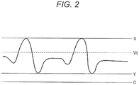
- Fig. 2 is a graph of a detected waveform of the radio receiver.
- Fig. 2 illustrates the relationship between Vt, X, and Y.
- the comparator 5 determines that the target wave signal is present, for a portion that is equal to or larger than the threshold value Vt in the envelope, and determines that no target wave signal is present, for a portion smaller than the threshold value Vt in the envelope.
- the antenna 2 of the radio receiver 1 receives the impulse-radio UWB transmitted from the external radio transmitter, and transmits the impulse-radio UWB received to the LNA 3.
- the LNA 3 amplifies the impulse-radio UWB while suppressing the noise mixed with the impulse-radio UWB received by the antenna 2.
- this arrangement enables the signal to be detected precisely with the influence of the noise inhibited.
- the LNA 3 transmits the impulse-radio UWB amplified to the envelope detector 4.
- the envelope detector 4 detects the amplitude in voltage of the signal, on the basis of the envelope of the signal output from the LNA 3. Then, the envelope detector 4 transmits the amplitude in voltage detected, to the comparator 5, the maximum-peak detection unit 8, and the minimum-peak detection unit 9.
- the comparator 5 compares the signal strength in voltage detected by the envelope detector 4, to the predetermined threshold value.
- the comparator 5 determines that the target wave signal is present, for the signal strength that is equal to or larger than the threshold value, and determines that no target wave signal is present, for the signal strength smaller than the threshold value, to generate the digital data.
- the baseband unit 6 demodulates the received data, and then generates the digital signal with the state where the target wave signal is present set as 1 and the state where no target wave signal is present set as 0 in the detected result of the comparator 5.
- the baseband unit 6 provides the digital signal as the output data for the processing of the different device not illustrated.
- the baseband unit 6 measures the error rate of the received data.
- the measurement of the error rate is performed, for example, on the basis of a data correction rate performed to the received data or a result of error detection.
- the measurement of the error rate is not limited to this method, and thus may be performed in a different method.
- the error rate measured by the baseband unit 6 is transmitted from the baseband unit 6 to the MPU 7.
- the MPU 7 calculates Z that minimizes the error rate of the received signal, on the basis of the error rate acquired by the baseband unit 6.
- the correction coefficient Z calculated is transmitted from the MPU 7 to the arithmetic unit 10.
- the maximum-peak detection unit 8 detects the maximum value X of the amplitude in voltage transmitted from the envelope detector 4, and transmits the maximum value X to the arithmetic unit 10.
- the minimum-peak detection unit 9 detects the minimum value Y of the amplitude in voltage transmitted from the envelope detector 4, and transmits the minimum value Y to the arithmetic unit 10 and the arithmetic unit 11.
- the arithmetic unit 10 performs the arithmetic of (X - Y)/Z with the maximum value X transmitted from the maximum-peak detection unit 8, the minimum value Y transmitted from the minimum-peak detection unit 9, and the correction coefficient Z transmitted from the MPU 7.
- the arithmetic result of the arithmetic unit 10 is transmitted from the arithmetic unit 10 to the arithmetic unit 11.
- the arithmetic unit 11 performs the arithmetic of Expression (1) described above, with the arithmetic result of (X - Y)/Z of the arithmetic unit 10 and the minimum value Y detected by the minimum-peak detection unit 9, to calculate the corrected threshold value Vt.
- the corrected threshold value Vt calculated in this manner is transmitted from the arithmetic unit 11 to the comparator 5.
- the comparator 5 that has received the corrected threshold value Vt performs the subsequent operation with the corrected threshold value Vt.
- the radio receiver 1 calculates a new corrected threshold value Vt with second measurement of the error rate in a similar manner to the processing described above.
- the radio receiver 1 adjusts the threshold value, corresponding to a communication situation, to enable a weak received wave to be detected. As a result, even in a case where the impulse-radio UWB is used, communication distance can be extended.
- the radio receiver 1 includes the single reception unit, namely, the antenna 2, the LNA 3, and the envelope detector 4 on a one-by-one basis.
- the present invention is not limited to this, and thus a plurality of reception units may be provided.
- an adder that adds the envelopes output from the plurality of reception units is provided between the reception units and the comparator 5.
- the provision of the adder in this manner allows the power of the impulse-radio UWB received by the plurality of reception units to increase theoretically in accordance with the number of reception units. This arrangement enables the received power of the impulse-radio UWB to increase, so that longer-haul radio communication can be achieved than ever before.
Landscapes
- Engineering & Computer Science (AREA)
- Computer Networks & Wireless Communication (AREA)
- Signal Processing (AREA)
- Power Engineering (AREA)
- Quality & Reliability (AREA)
- Circuits Of Receivers In General (AREA)
- Noise Elimination (AREA)
Abstract
Description
- The present invention relates to a radio receiver capable of improving receiving sensitivity while using an impulse-radio ultra wide band (IR-UWB).
- A technology that uses an impulse-radio UWB and performs communication with a pulse having an extremely narrow time width, has been known as a recent noticeable radio communication technology (refer to Patent Literature 1) .
- In the impulse-radio UWB, a pulse signal having a considerably short time width of 1 nsec or less is used and the position, amplitude, or phase on the time axis of the pulse signal is changed to transmit information.
- The frequency bandwidth that a UWB signal occupies is considerably wide over a range of 500 MHz to several GHz. As a result, high data-rate signal transmission or high-precision ranging is achieved because of use of a pulse signal having a considerably short time width of 1 nsec.
- A radio communication scheme using the impulse-radio UWB enables the configuration of a transmitter/receiver to be simple, manufacturing costs to be kept low, and power consumption to be kept low.
- Patent Literature 1:
JP 2015-61105 A - In a case where the impulse-radio UWB is used, on-off keying (OOK) modulation based on on-off control of a pulse or pulse position modulation (PPM) modulation based on the position of the pulse is usually employed as basic processing, and a receiver needs to perform power detection in both cases.
- On the receiver side, there is a need to perform processing of determining the presence or absence of the pulse, in a process of demodulating received data, and it is important to eliminate influence, such as noise or the variation of a received waveform, and to pick up only a target wave accurately.
- Specifically, a received wave that the receiver receives includes noise in addition to the target wave, and the peak level of the received wave drastically varies, depending on propagation paths.
- Thus, in order to prevent the noise from being wrongly determined as a signal pulse, it is considered that a threshold value for distinguishing the signal pulse and the noise is set high.
- However, if the threshold value is set high, the receiver cannot detect the signal pulse in a case where the target wave is weak, and thus a degradation in receiving sensitivity occurs.
- Thus, the present invention has been made in consideration of the problem described above, and an object of the present invention is to provide a radio receiver capable of improving receiving sensitivity while using a UWB.
- A radio receiver according to a first aspect of the invention, is configured to use an impulse-radio UWB and includes: a reception antenna configured to receive the impulse-radio UWB; a reception unit configured to amplify the impulse-radio UWB received, the reception unit configured to perform detection of an envelope of the impulse-radio UWB; a maximum-peak detection unit configured to detect a maximum value of the envelope; a minimum-peak detection unit configured to detect a minimum value of the envelope; a comparator configured to acquire signal data from the envelope, with an initial threshold value; a baseband unit configured to measure an error rate of the signal data; a micro processing unit (MPU) configured to calculate a correction coefficient, based on the error rate; and an arithmetic unit configured to calculate a corrected threshold value, based on the maximum value, the minimum value, and the correction coefficient, the arithmetic unit configured to transmit the corrected threshold value to the comparator. The comparator acquires the signal data from the envelope, based on the corrected threshold value transmitted from the arithmetic unit.
- According to a radio receiver of a second aspect of the invention, in the first aspect of the invention, the arithmetic unit performs arithmetic of Expression (1), based on the maximum value X, the minimum value Y, and the correction coefficient Z, calculates the corrected threshold value Vt, and transmits the corrected threshold value Vt to the comparator.
[Mathematical Formula 1]
- According to a radio receiver of a third aspect of the invention, in the first or second aspect of the invention, a bit error rate is used as the error rate, and the MPU calculates the correction coefficient, based on the bit error rate.
- According to a radio receiver of a fourth aspect of the invention, in the first or second aspect of the invention, a packet error rate is used as the error rate, and the MPU calculates the correction coefficient, based on the packet error rate.
- A radio receiver of a fifth aspect of the invention, in any one of the first to fourth aspects of the invention, further includes: a plurality of the reception units; and an adder configured to add the envelopes from the plurality of the reception units.
- According to a radio receiver of a sixth aspect of the invention, in any one of the first to fifth aspects of the invention, the baseband unit measures the error rate per predetermined period.
- The present invention including the configurations described above, enables a radio receiver capable of improving receiving sensitivity while using an impulse-radio UWB, to be provided.
-
-
Fig. 1 is a block diagram of the system configuration of a radio receiver according to an embodiment of the present invention. -
Fig. 2 is a graph of a detected waveform of the radio receiver. - A radio receiver and a radio communication system according to an embodiment of the present invention, will be described below.
-
Fig. 1 is a block diagram of the system configuration of the radio receiver according to the embodiment of the present invention. Theradio receiver 1 according to the present embodiment, includes anantenna 2, a low noise amplifier (LNA) 3, an envelope detector 4, a comparator 5, abaseband unit 6, a micro processing unit (MPU) 7, a maximum-peak detection unit 8, a minimum-peak detection unit 9, andarithmetic units - The
antenna 2 receives an impulse-radio UWB transmitted from a transmitter. - For the impulse-radio UWB received through the
antenna 2, the LNA 3 amplifies a UWB signal while suppressing noise superimposed in an amplification process. - On the basis of the envelope of the signal output from the LNA 3, the envelope detector 4 detects the amplitude in voltage of the signal. Note that, for convenience, the
antenna 2, the LNA 3, and the envelope detector 4 are collectively defined as a reception unit. - The comparator 5 compares the signal strength in voltage detected by the envelope detector 4, to a predetermined threshold value. The comparator 5 determines that a target wave signal is present, for the signal strength that is equal to or larger than the threshold value, and determines that no target wave signal is present, for the signal strength that is smaller than the threshold value.
- The
baseband unit 6 demodulates received data, and then generates a digital signal with the state where the target wave signal is present set as 1 and the state where no target wave signal is present set as 0 in a detected result of the comparator 5. Thebaseband unit 6 provides the digital signal as output data for processing of a different device not illustrated. The modulation and demodulation for the transmission and reception of the data can be performed in any other schemes, and pulse density modulation and demodulation can be used as an example. - The
baseband unit 6 measures the error rate of the received data. As the error rate to be measured, any error rate, such as a bit error rate or a packet error rate, can be adopted. The baseband unit can measure the error rate with any timing. For example, the measurement is performed at intervals of a predetermined plurality of packets. - The MPU 7 includes a control mechanism that controls the entire configuration of the
radio receiver 1. - The maximum-peak detection unit 8 detects the maximum value in the envelope detected by the envelope detector 4 over a predetermined period. The maximum value in the envelope over the predetermined period, is denoted as X.
- The minimum-
peak detection unit 9 detects the minimum value in the envelope detected by the envelope detector 4 over the predetermined period. The minimum value in the envelope over the predetermined period, is denoted as Y. - The
arithmetic unit 10 performs arithmetic of (X - Y)/Z. Here, Z represents a correction coefficient calculated by the MPU, the correction coefficient minimizing the error rate of the received signal. - The
arithmetic unit 11 adds Y to an arithmetic result of thearithmetic unit 10. - That is the
arithmetic units
[Mathematical Formula 1]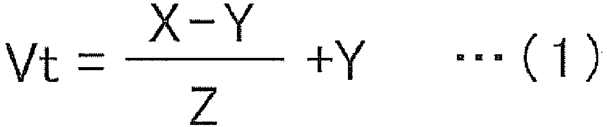
- Then, the corrected threshold value Vt calculated is transmitted to the comparator 5, so that the corrected threshold value Vt is supplied to the subsequent processing of the comparator 5.
-
Fig. 2 is a graph of a detected waveform of the radio receiver.Fig. 2 illustrates the relationship between Vt, X, and Y. The comparator 5 determines that the target wave signal is present, for a portion that is equal to or larger than the threshold value Vt in the envelope, and determines that no target wave signal is present, for a portion smaller than the threshold value Vt in the envelope. - Next, the operation of the
radio receiver 1 having the configuration described above, will be described in detail. - First, the
antenna 2 of theradio receiver 1 receives the impulse-radio UWB transmitted from the external radio transmitter, and transmits the impulse-radio UWB received to the LNA 3. - Next, the LNA 3 amplifies the impulse-radio UWB while suppressing the noise mixed with the impulse-radio UWB received by the
antenna 2. For the impulse-radio UWB that is a feeble signal and is susceptible to the noise, this arrangement enables the signal to be detected precisely with the influence of the noise inhibited. Then, the LNA 3 transmits the impulse-radio UWB amplified to the envelope detector 4. - Next, the envelope detector 4 detects the amplitude in voltage of the signal, on the basis of the envelope of the signal output from the LNA 3. Then, the envelope detector 4 transmits the amplitude in voltage detected, to the comparator 5, the maximum-peak detection unit 8, and the minimum-
peak detection unit 9. - Next, the comparator 5 compares the signal strength in voltage detected by the envelope detector 4, to the predetermined threshold value. The comparator 5 determines that the target wave signal is present, for the signal strength that is equal to or larger than the threshold value, and determines that no target wave signal is present, for the signal strength smaller than the threshold value, to generate the digital data.
- Next, the
baseband unit 6 demodulates the received data, and then generates the digital signal with the state where the target wave signal is present set as 1 and the state where no target wave signal is present set as 0 in the detected result of the comparator 5. Thebaseband unit 6 provides the digital signal as the output data for the processing of the different device not illustrated. Thebaseband unit 6 measures the error rate of the received data. - The measurement of the error rate is performed, for example, on the basis of a data correction rate performed to the received data or a result of error detection. However, the measurement of the error rate is not limited to this method, and thus may be performed in a different method.
- The error rate measured by the
baseband unit 6 is transmitted from thebaseband unit 6 to theMPU 7. - Next, the
MPU 7 calculates Z that minimizes the error rate of the received signal, on the basis of the error rate acquired by thebaseband unit 6. The correction coefficient Z calculated is transmitted from theMPU 7 to thearithmetic unit 10. - Meanwhile, the maximum-peak detection unit 8 detects the maximum value X of the amplitude in voltage transmitted from the envelope detector 4, and transmits the maximum value X to the
arithmetic unit 10. - The minimum-
peak detection unit 9 detects the minimum value Y of the amplitude in voltage transmitted from the envelope detector 4, and transmits the minimum value Y to thearithmetic unit 10 and thearithmetic unit 11. - The
arithmetic unit 10 performs the arithmetic of (X - Y)/Z with the maximum value X transmitted from the maximum-peak detection unit 8, the minimum value Y transmitted from the minimum-peak detection unit 9, and the correction coefficient Z transmitted from theMPU 7. The arithmetic result of thearithmetic unit 10 is transmitted from thearithmetic unit 10 to thearithmetic unit 11. - The
arithmetic unit 11 performs the arithmetic of Expression (1) described above, with the arithmetic result of (X - Y)/Z of thearithmetic unit 10 and the minimum value Y detected by the minimum-peak detection unit 9, to calculate the corrected threshold value Vt. - The corrected threshold value Vt calculated in this manner, is transmitted from the
arithmetic unit 11 to the comparator 5. The comparator 5 that has received the corrected threshold value Vt, performs the subsequent operation with the corrected threshold value Vt. - Then, a determined result for the presence or absence of the signal acquired by the comparator 5 with the corrected threshold value Vt, is transmitted to the
baseband unit 6. After that, theradio receiver 1 calculates a new corrected threshold value Vt with second measurement of the error rate in a similar manner to the processing described above. - The
radio receiver 1 according to the present embodiment adjusts the threshold value, corresponding to a communication situation, to enable a weak received wave to be detected. As a result, even in a case where the impulse-radio UWB is used, communication distance can be extended. - Note that the
radio receiver 1 according to the embodiment described above includes the single reception unit, namely, theantenna 2, the LNA 3, and the envelope detector 4 on a one-by-one basis. However, the present invention is not limited to this, and thus a plurality of reception units may be provided. - In this case, an adder that adds the envelopes output from the plurality of reception units, is provided between the reception units and the comparator 5.
- The provision of the adder in this manner allows the power of the impulse-radio UWB received by the plurality of reception units to increase theoretically in accordance with the number of reception units. This arrangement enables the received power of the impulse-radio UWB to increase, so that longer-haul radio communication can be achieved than ever before.
-
- 1 radio receiver
- 2 antenna
- 3 low noise amplifier (LNA)
- 4 envelope detector
- 5 comparator
- 6 baseband unit
- 7 micro processing unit (MPU)
- 8 maximum-peak detection unit
- 9 minimum-peak detection unit
- 10, 11 arithmetic unit
Claims (6)
- A radio receiver configured to use an impulse-radio UWB, the radio receiver comprising:a reception antenna configured to receive the impulse-radio UWB;a reception unit configured to amplify the impulse-radio UWB received, the reception unit configured to perform detection of an envelope of the impulse-radio UWB;a maximum-peak detection unit configured to detect a maximum value of the envelope;a minimum-peak detection unit configured to detect a minimum value of the envelope;a comparator configured to acquire signal data from the envelope, with an initial threshold value;a baseband unit configured to measure an error rate of the signal data;an MPU configured to calculate a correction coefficient, based on the error rate; andan arithmetic unit configured to calculate a corrected threshold value, based on the maximum value, the minimum value, and the correction coefficient, the arithmetic unit configured to transmit the corrected threshold value to the comparator,wherein the comparator acquires the signal data from the envelope, based on the corrected threshold value transmitted from the arithmetic unit.
- The radio receiver according to claim 1, wherein the arithmetic unit performs arithmetic of Expression (1), based on the maximum value X, the minimum value Y, and the correction coefficient Z, calculates a corrected threshold value Vt, and transmits the corrected threshold value Vt to the comparator.
[Mathematical Formula 1]
- The radio receiver according to claim 1 or 2, wherein a bit error rate is used as the error rate, and the MPU calculates the correction coefficient, based on the bit error rate.
- The radio receiver according to claim 1 or 2, wherein a packet error rate is used as the error rate, and the MPU calculates the correction coefficient, based on the packet error rate.
- The radio receiver according to any one of claims 1 to 4, comprising:a plurality of the reception units; andan adder configured to add the envelopes from the plurality of the reception units.
- The radio receiver according to any one of claims 1 to 5, wherein the baseband unit measures the error rate per predetermined period.
Applications Claiming Priority (2)
| Application Number | Priority Date | Filing Date | Title |
|---|---|---|---|
| JP2015246900A JP6653838B2 (en) | 2015-12-18 | 2015-12-18 | Wireless receiver |
| PCT/JP2016/086921 WO2017104615A1 (en) | 2015-12-18 | 2016-12-12 | Wireless receiver |
Publications (3)
| Publication Number | Publication Date |
|---|---|
| EP3393050A1 true EP3393050A1 (en) | 2018-10-24 |
| EP3393050A4 EP3393050A4 (en) | 2019-08-21 |
| EP3393050B1 EP3393050B1 (en) | 2022-05-04 |
Family
ID=59056645
Family Applications (1)
| Application Number | Title | Priority Date | Filing Date |
|---|---|---|---|
| EP16875592.4A Active EP3393050B1 (en) | 2015-12-18 | 2016-12-12 | Wireless receiver |
Country Status (4)
| Country | Link |
|---|---|
| US (1) | US10277263B2 (en) |
| EP (1) | EP3393050B1 (en) |
| JP (1) | JP6653838B2 (en) |
| WO (1) | WO2017104615A1 (en) |
Cited By (2)
| Publication number | Priority date | Publication date | Assignee | Title |
|---|---|---|---|---|
| KR20230079550A (en) * | 2021-11-29 | 2023-06-07 | 연세대학교 산학협력단 | Impulse wireless communication system |
| US20240098677A1 (en) * | 2021-02-08 | 2024-03-21 | Qualcomm Incorporated | Impulse radio ultra-wideband (ir-uwb) using long-term evolution (lte) positioning protocol (lpp) |
Family Cites Families (7)
| Publication number | Priority date | Publication date | Assignee | Title |
|---|---|---|---|---|
| JPH10163877A (en) | 1996-11-28 | 1998-06-19 | Sony Corp | Threshold control circuit of multi-level comparator in demodulation circuit |
| US7209523B1 (en) * | 1997-05-16 | 2007-04-24 | Multispectral Solutions, Inc. | Ultra-wideband receiver and transmitter |
| JP2000078211A (en) * | 1998-09-03 | 2000-03-14 | Sony Corp | Information demodulating apparatus and method, and providing medium |
| US7539271B2 (en) * | 2002-08-16 | 2009-05-26 | Wisair Ltd. | System and method for multi-band ultra-wide band signal generators |
| KR100818246B1 (en) * | 2007-04-18 | 2008-04-02 | 삼성전자주식회사 | Communication device and method using chaotic signal |
| KR101141050B1 (en) * | 2009-12-15 | 2012-05-03 | 한국전기연구원 | APPARATUS AND METHOD FOR DETECTING AN IMPULSE SIGNAL and impulse train |
| JP6256739B2 (en) | 2013-09-17 | 2018-01-10 | 国立研究開発法人情報通信研究機構 | Wireless transmitter, wireless receiver, wireless communication system, and wireless communication method |
-
2015
- 2015-12-18 JP JP2015246900A patent/JP6653838B2/en active Active
-
2016
- 2016-12-12 EP EP16875592.4A patent/EP3393050B1/en active Active
- 2016-12-12 US US16/061,963 patent/US10277263B2/en active Active
- 2016-12-12 WO PCT/JP2016/086921 patent/WO2017104615A1/en not_active Ceased
Cited By (4)
| Publication number | Priority date | Publication date | Assignee | Title |
|---|---|---|---|---|
| US20240098677A1 (en) * | 2021-02-08 | 2024-03-21 | Qualcomm Incorporated | Impulse radio ultra-wideband (ir-uwb) using long-term evolution (lte) positioning protocol (lpp) |
| US12550103B2 (en) * | 2021-02-08 | 2026-02-10 | Qualcomm Incorporated | Impulse radio ultra-wideband (ir-uwb) using long- term evolution (lte) positioning protocol (lpp) |
| KR20230079550A (en) * | 2021-11-29 | 2023-06-07 | 연세대학교 산학협력단 | Impulse wireless communication system |
| KR102694448B1 (en) | 2021-11-29 | 2024-08-09 | 연세대학교 산학협력단 | Impulse wireless communication system |
Also Published As
| Publication number | Publication date |
|---|---|
| EP3393050A4 (en) | 2019-08-21 |
| JP2017112553A (en) | 2017-06-22 |
| JP6653838B2 (en) | 2020-02-26 |
| US20180367176A1 (en) | 2018-12-20 |
| WO2017104615A1 (en) | 2017-06-22 |
| US10277263B2 (en) | 2019-04-30 |
| EP3393050B1 (en) | 2022-05-04 |
Similar Documents
| Publication | Publication Date | Title |
|---|---|---|
| US9264280B1 (en) | Automatic received gain control | |
| US7421012B1 (en) | Antenna diversity technique for wireless communication | |
| US8948238B2 (en) | Handling complex signal parameters | |
| JP2013076702A (en) | Method for determining line-of-sight (los) distance between remote communications devices | |
| US7746812B2 (en) | Reliable packet detection in a wireless receiver when packets contain a known repetitive sequence | |
| CN106301412B (en) | Preemptive Automatic Gain Control (AGC) for Interference Mitigation | |
| MX2023012846A (en) | Collision detection method. | |
| US8254437B2 (en) | Transmitting apparatus, receiving apparatus and communication system | |
| EP2628340A1 (en) | System and method for selective channel removal in multi-channel receivers | |
| CN107872284A (en) | The Self-excitation Detection method and device of wireless discharging-directly station | |
| US8787440B2 (en) | Determination of receive data values | |
| EP3393050B1 (en) | Wireless receiver | |
| US20070110126A1 (en) | Radio communication system and communication apparatus | |
| US8175274B2 (en) | Range measurement apparatus and method using chaotic UWB wireless communication | |
| US20030045250A1 (en) | Method and apparatus for detecting power levels of varying envelope signals | |
| US9325557B2 (en) | Radio communication apparatus and pulse signal transmission method in radio communication apparatus | |
| US9891311B2 (en) | Method of secure RF ranging under strong multipath reflections | |
| CN115333557B (en) | Wake-up transceiver system of UWB equipment | |
| US9014234B2 (en) | Communication system and communication method | |
| EP2258044A1 (en) | System and method of companding an input signal of an energy detecting receiver | |
| US20090154541A1 (en) | Transmitter, receiver and communication terminal system | |
| US20120315857A1 (en) | Wireless communication method and apparatus | |
| US10939468B2 (en) | Clear channel assessment | |
| KR100888460B1 (en) | Pulse Period Modulator and Method | |
| KR101141044B1 (en) | Energy detection based ir-uwb system for increasing signal detection probability using continuous pulses |
Legal Events
| Date | Code | Title | Description |
|---|---|---|---|
| STAA | Information on the status of an ep patent application or granted ep patent |
Free format text: STATUS: THE INTERNATIONAL PUBLICATION HAS BEEN MADE |
|
| PUAI | Public reference made under article 153(3) epc to a published international application that has entered the european phase |
Free format text: ORIGINAL CODE: 0009012 |
|
| STAA | Information on the status of an ep patent application or granted ep patent |
Free format text: STATUS: REQUEST FOR EXAMINATION WAS MADE |
|
| 17P | Request for examination filed |
Effective date: 20180615 |
|
| AK | Designated contracting states |
Kind code of ref document: A1 Designated state(s): AL AT BE BG CH CY CZ DE DK EE ES FI FR GB GR HR HU IE IS IT LI LT LU LV MC MK MT NL NO PL PT RO RS SE SI SK SM TR |
|
| AX | Request for extension of the european patent |
Extension state: BA ME |
|
| RAP1 | Party data changed (applicant data changed or rights of an application transferred) |
Owner name: NATIONAL INSTITUTE OF INFORMATION AND COMMUNICATIO Owner name: GIT JAPAN INCORPORATED |
|
| DAV | Request for validation of the european patent (deleted) | ||
| DAX | Request for extension of the european patent (deleted) | ||
| A4 | Supplementary search report drawn up and despatched |
Effective date: 20190718 |
|
| RIC1 | Information provided on ipc code assigned before grant |
Ipc: H04B 7/08 20060101ALI20190712BHEP Ipc: H04B 1/10 20060101ALI20190712BHEP Ipc: H04L 27/06 20060101ALI20190712BHEP Ipc: G01S 7/285 20060101ALI20190712BHEP Ipc: H04L 25/06 20060101ALI20190712BHEP Ipc: H04B 1/7163 20110101AFI20190712BHEP Ipc: H04L 1/20 20060101ALI20190712BHEP Ipc: H04B 1/16 20060101ALI20190712BHEP Ipc: H04B 1/00 20060101ALI20190712BHEP |
|
| GRAP | Despatch of communication of intention to grant a patent |
Free format text: ORIGINAL CODE: EPIDOSNIGR1 |
|
| STAA | Information on the status of an ep patent application or granted ep patent |
Free format text: STATUS: GRANT OF PATENT IS INTENDED |
|
| INTG | Intention to grant announced |
Effective date: 20211201 |
|
| GRAS | Grant fee paid |
Free format text: ORIGINAL CODE: EPIDOSNIGR3 |
|
| GRAA | (expected) grant |
Free format text: ORIGINAL CODE: 0009210 |
|
| STAA | Information on the status of an ep patent application or granted ep patent |
Free format text: STATUS: THE PATENT HAS BEEN GRANTED |
|
| AK | Designated contracting states |
Kind code of ref document: B1 Designated state(s): AL AT BE BG CH CY CZ DE DK EE ES FI FR GB GR HR HU IE IS IT LI LT LU LV MC MK MT NL NO PL PT RO RS SE SI SK SM TR |
|
| REG | Reference to a national code |
Ref country code: GB Ref legal event code: FG4D |
|
| REG | Reference to a national code |
Ref country code: CH Ref legal event code: EP |
|
| REG | Reference to a national code |
Ref country code: AT Ref legal event code: REF Ref document number: 1490238 Country of ref document: AT Kind code of ref document: T Effective date: 20220515 |
|
| REG | Reference to a national code |
Ref country code: NL Ref legal event code: FP |
|
| REG | Reference to a national code |
Ref country code: DE Ref legal event code: R096 Ref document number: 602016071903 Country of ref document: DE |
|
| REG | Reference to a national code |
Ref country code: IE Ref legal event code: FG4D |
|
| REG | Reference to a national code |
Ref country code: LT Ref legal event code: MG9D |
|
| REG | Reference to a national code |
Ref country code: AT Ref legal event code: MK05 Ref document number: 1490238 Country of ref document: AT Kind code of ref document: T Effective date: 20220504 |
|
| PG25 | Lapsed in a contracting state [announced via postgrant information from national office to epo] |
Ref country code: SE Free format text: LAPSE BECAUSE OF FAILURE TO SUBMIT A TRANSLATION OF THE DESCRIPTION OR TO PAY THE FEE WITHIN THE PRESCRIBED TIME-LIMIT Effective date: 20220504 Ref country code: PT Free format text: LAPSE BECAUSE OF FAILURE TO SUBMIT A TRANSLATION OF THE DESCRIPTION OR TO PAY THE FEE WITHIN THE PRESCRIBED TIME-LIMIT Effective date: 20220905 Ref country code: NO Free format text: LAPSE BECAUSE OF FAILURE TO SUBMIT A TRANSLATION OF THE DESCRIPTION OR TO PAY THE FEE WITHIN THE PRESCRIBED TIME-LIMIT Effective date: 20220804 Ref country code: LT Free format text: LAPSE BECAUSE OF FAILURE TO SUBMIT A TRANSLATION OF THE DESCRIPTION OR TO PAY THE FEE WITHIN THE PRESCRIBED TIME-LIMIT Effective date: 20220504 Ref country code: HR Free format text: LAPSE BECAUSE OF FAILURE TO SUBMIT A TRANSLATION OF THE DESCRIPTION OR TO PAY THE FEE WITHIN THE PRESCRIBED TIME-LIMIT Effective date: 20220504 Ref country code: GR Free format text: LAPSE BECAUSE OF FAILURE TO SUBMIT A TRANSLATION OF THE DESCRIPTION OR TO PAY THE FEE WITHIN THE PRESCRIBED TIME-LIMIT Effective date: 20220805 Ref country code: FI Free format text: LAPSE BECAUSE OF FAILURE TO SUBMIT A TRANSLATION OF THE DESCRIPTION OR TO PAY THE FEE WITHIN THE PRESCRIBED TIME-LIMIT Effective date: 20220504 Ref country code: ES Free format text: LAPSE BECAUSE OF FAILURE TO SUBMIT A TRANSLATION OF THE DESCRIPTION OR TO PAY THE FEE WITHIN THE PRESCRIBED TIME-LIMIT Effective date: 20220504 Ref country code: BG Free format text: LAPSE BECAUSE OF FAILURE TO SUBMIT A TRANSLATION OF THE DESCRIPTION OR TO PAY THE FEE WITHIN THE PRESCRIBED TIME-LIMIT Effective date: 20220804 Ref country code: AT Free format text: LAPSE BECAUSE OF FAILURE TO SUBMIT A TRANSLATION OF THE DESCRIPTION OR TO PAY THE FEE WITHIN THE PRESCRIBED TIME-LIMIT Effective date: 20220504 |
|
| PG25 | Lapsed in a contracting state [announced via postgrant information from national office to epo] |
Ref country code: RS Free format text: LAPSE BECAUSE OF FAILURE TO SUBMIT A TRANSLATION OF THE DESCRIPTION OR TO PAY THE FEE WITHIN THE PRESCRIBED TIME-LIMIT Effective date: 20220504 Ref country code: PL Free format text: LAPSE BECAUSE OF FAILURE TO SUBMIT A TRANSLATION OF THE DESCRIPTION OR TO PAY THE FEE WITHIN THE PRESCRIBED TIME-LIMIT Effective date: 20220504 Ref country code: LV Free format text: LAPSE BECAUSE OF FAILURE TO SUBMIT A TRANSLATION OF THE DESCRIPTION OR TO PAY THE FEE WITHIN THE PRESCRIBED TIME-LIMIT Effective date: 20220504 Ref country code: IS Free format text: LAPSE BECAUSE OF FAILURE TO SUBMIT A TRANSLATION OF THE DESCRIPTION OR TO PAY THE FEE WITHIN THE PRESCRIBED TIME-LIMIT Effective date: 20220904 |
|
| PG25 | Lapsed in a contracting state [announced via postgrant information from national office to epo] |
Ref country code: SM Free format text: LAPSE BECAUSE OF FAILURE TO SUBMIT A TRANSLATION OF THE DESCRIPTION OR TO PAY THE FEE WITHIN THE PRESCRIBED TIME-LIMIT Effective date: 20220504 Ref country code: SK Free format text: LAPSE BECAUSE OF FAILURE TO SUBMIT A TRANSLATION OF THE DESCRIPTION OR TO PAY THE FEE WITHIN THE PRESCRIBED TIME-LIMIT Effective date: 20220504 Ref country code: RO Free format text: LAPSE BECAUSE OF FAILURE TO SUBMIT A TRANSLATION OF THE DESCRIPTION OR TO PAY THE FEE WITHIN THE PRESCRIBED TIME-LIMIT Effective date: 20220504 Ref country code: EE Free format text: LAPSE BECAUSE OF FAILURE TO SUBMIT A TRANSLATION OF THE DESCRIPTION OR TO PAY THE FEE WITHIN THE PRESCRIBED TIME-LIMIT Effective date: 20220504 Ref country code: DK Free format text: LAPSE BECAUSE OF FAILURE TO SUBMIT A TRANSLATION OF THE DESCRIPTION OR TO PAY THE FEE WITHIN THE PRESCRIBED TIME-LIMIT Effective date: 20220504 Ref country code: CZ Free format text: LAPSE BECAUSE OF FAILURE TO SUBMIT A TRANSLATION OF THE DESCRIPTION OR TO PAY THE FEE WITHIN THE PRESCRIBED TIME-LIMIT Effective date: 20220504 |
|
| REG | Reference to a national code |
Ref country code: DE Ref legal event code: R097 Ref document number: 602016071903 Country of ref document: DE |
|
| PLBE | No opposition filed within time limit |
Free format text: ORIGINAL CODE: 0009261 |
|
| STAA | Information on the status of an ep patent application or granted ep patent |
Free format text: STATUS: NO OPPOSITION FILED WITHIN TIME LIMIT |
|
| PG25 | Lapsed in a contracting state [announced via postgrant information from national office to epo] |
Ref country code: AL Free format text: LAPSE BECAUSE OF FAILURE TO SUBMIT A TRANSLATION OF THE DESCRIPTION OR TO PAY THE FEE WITHIN THE PRESCRIBED TIME-LIMIT Effective date: 20220504 |
|
| 26N | No opposition filed |
Effective date: 20230207 |
|
| PG25 | Lapsed in a contracting state [announced via postgrant information from national office to epo] |
Ref country code: SI Free format text: LAPSE BECAUSE OF FAILURE TO SUBMIT A TRANSLATION OF THE DESCRIPTION OR TO PAY THE FEE WITHIN THE PRESCRIBED TIME-LIMIT Effective date: 20220504 |
|
| REG | Reference to a national code |
Ref country code: CH Ref legal event code: PL |
|
| REG | Reference to a national code |
Ref country code: BE Ref legal event code: MM Effective date: 20221231 |
|
| PG25 | Lapsed in a contracting state [announced via postgrant information from national office to epo] |
Ref country code: LU Free format text: LAPSE BECAUSE OF NON-PAYMENT OF DUE FEES Effective date: 20221212 |
|
| PG25 | Lapsed in a contracting state [announced via postgrant information from national office to epo] |
Ref country code: LI Free format text: LAPSE BECAUSE OF NON-PAYMENT OF DUE FEES Effective date: 20221231 Ref country code: CH Free format text: LAPSE BECAUSE OF NON-PAYMENT OF DUE FEES Effective date: 20221231 |
|
| PG25 | Lapsed in a contracting state [announced via postgrant information from national office to epo] |
Ref country code: BE Free format text: LAPSE BECAUSE OF NON-PAYMENT OF DUE FEES Effective date: 20221231 |
|
| PG25 | Lapsed in a contracting state [announced via postgrant information from national office to epo] |
Ref country code: IT Free format text: LAPSE BECAUSE OF FAILURE TO SUBMIT A TRANSLATION OF THE DESCRIPTION OR TO PAY THE FEE WITHIN THE PRESCRIBED TIME-LIMIT Effective date: 20220504 |
|
| PG25 | Lapsed in a contracting state [announced via postgrant information from national office to epo] |
Ref country code: HU Free format text: LAPSE BECAUSE OF FAILURE TO SUBMIT A TRANSLATION OF THE DESCRIPTION OR TO PAY THE FEE WITHIN THE PRESCRIBED TIME-LIMIT; INVALID AB INITIO Effective date: 20161212 |
|
| PG25 | Lapsed in a contracting state [announced via postgrant information from national office to epo] |
Ref country code: CY Free format text: LAPSE BECAUSE OF FAILURE TO SUBMIT A TRANSLATION OF THE DESCRIPTION OR TO PAY THE FEE WITHIN THE PRESCRIBED TIME-LIMIT Effective date: 20220504 |
|
| PG25 | Lapsed in a contracting state [announced via postgrant information from national office to epo] |
Ref country code: MK Free format text: LAPSE BECAUSE OF FAILURE TO SUBMIT A TRANSLATION OF THE DESCRIPTION OR TO PAY THE FEE WITHIN THE PRESCRIBED TIME-LIMIT Effective date: 20220504 |
|
| PG25 | Lapsed in a contracting state [announced via postgrant information from national office to epo] |
Ref country code: MC Free format text: LAPSE BECAUSE OF FAILURE TO SUBMIT A TRANSLATION OF THE DESCRIPTION OR TO PAY THE FEE WITHIN THE PRESCRIBED TIME-LIMIT Effective date: 20220504 |
|
| PG25 | Lapsed in a contracting state [announced via postgrant information from national office to epo] |
Ref country code: MC Free format text: LAPSE BECAUSE OF FAILURE TO SUBMIT A TRANSLATION OF THE DESCRIPTION OR TO PAY THE FEE WITHIN THE PRESCRIBED TIME-LIMIT Effective date: 20220504 |
|
| PG25 | Lapsed in a contracting state [announced via postgrant information from national office to epo] |
Ref country code: MT Free format text: LAPSE BECAUSE OF FAILURE TO SUBMIT A TRANSLATION OF THE DESCRIPTION OR TO PAY THE FEE WITHIN THE PRESCRIBED TIME-LIMIT Effective date: 20220504 |
|
| PG25 | Lapsed in a contracting state [announced via postgrant information from national office to epo] |
Ref country code: BG Free format text: LAPSE BECAUSE OF FAILURE TO SUBMIT A TRANSLATION OF THE DESCRIPTION OR TO PAY THE FEE WITHIN THE PRESCRIBED TIME-LIMIT Effective date: 20220504 |
|
| PG25 | Lapsed in a contracting state [announced via postgrant information from national office to epo] |
Ref country code: BG Free format text: LAPSE BECAUSE OF FAILURE TO SUBMIT A TRANSLATION OF THE DESCRIPTION OR TO PAY THE FEE WITHIN THE PRESCRIBED TIME-LIMIT Effective date: 20220504 |
|
| PG25 | Lapsed in a contracting state [announced via postgrant information from national office to epo] |
Ref country code: TR Free format text: LAPSE BECAUSE OF FAILURE TO SUBMIT A TRANSLATION OF THE DESCRIPTION OR TO PAY THE FEE WITHIN THE PRESCRIBED TIME-LIMIT Effective date: 20220504 |
|
| PGFP | Annual fee paid to national office [announced via postgrant information from national office to epo] |
Ref country code: DE Payment date: 20251208 Year of fee payment: 10 |
|
| PGFP | Annual fee paid to national office [announced via postgrant information from national office to epo] |
Ref country code: GB Payment date: 20251229 Year of fee payment: 10 |
|
| PGFP | Annual fee paid to national office [announced via postgrant information from national office to epo] |
Ref country code: NL Payment date: 20251223 Year of fee payment: 10 Ref country code: FR Payment date: 20251223 Year of fee payment: 10 |
|
| PGFP | Annual fee paid to national office [announced via postgrant information from national office to epo] |
Ref country code: IE Payment date: 20251217 Year of fee payment: 10 |