EP3392943A1 - Fuel cell system and control method for fuel cell system - Google Patents
Fuel cell system and control method for fuel cell system Download PDFInfo
- Publication number
- EP3392943A1 EP3392943A1 EP16875300.2A EP16875300A EP3392943A1 EP 3392943 A1 EP3392943 A1 EP 3392943A1 EP 16875300 A EP16875300 A EP 16875300A EP 3392943 A1 EP3392943 A1 EP 3392943A1
- Authority
- EP
- European Patent Office
- Prior art keywords
- fuel
- water
- fuel cell
- cell system
- separator
- Prior art date
- Legal status (The legal status is an assumption and is not a legal conclusion. Google has not performed a legal analysis and makes no representation as to the accuracy of the status listed.)
- Granted
Links
- 239000000446 fuel Substances 0.000 title claims abstract description 404
- 238000000034 method Methods 0.000 title claims description 62
- XLYOFNOQVPJJNP-UHFFFAOYSA-N water Substances O XLYOFNOQVPJJNP-UHFFFAOYSA-N 0.000 claims abstract description 260
- 239000002828 fuel tank Substances 0.000 claims abstract description 70
- 238000011144 upstream manufacturing Methods 0.000 claims abstract description 12
- 239000007787 solid Substances 0.000 claims abstract description 9
- 238000002407 reforming Methods 0.000 claims abstract description 3
- 238000000926 separation method Methods 0.000 claims description 62
- 230000004913 activation Effects 0.000 claims description 51
- 238000011084 recovery Methods 0.000 claims description 27
- 230000006837 decompression Effects 0.000 claims description 16
- 239000012528 membrane Substances 0.000 claims description 13
- 230000007423 decrease Effects 0.000 claims description 11
- 230000003247 decreasing effect Effects 0.000 claims description 6
- 238000001704 evaporation Methods 0.000 claims description 4
- 238000001514 detection method Methods 0.000 claims description 2
- 239000007789 gas Substances 0.000 description 60
- 238000001994 activation Methods 0.000 description 44
- 239000003054 catalyst Substances 0.000 description 17
- 239000002737 fuel gas Substances 0.000 description 13
- LFQSCWFLJHTTHZ-UHFFFAOYSA-N Ethanol Chemical compound CCO LFQSCWFLJHTTHZ-UHFFFAOYSA-N 0.000 description 12
- 238000001816 cooling Methods 0.000 description 10
- 238000010586 diagram Methods 0.000 description 10
- 238000010248 power generation Methods 0.000 description 10
- 239000002994 raw material Substances 0.000 description 7
- 230000000694 effects Effects 0.000 description 4
- QVGXLLKOCUKJST-UHFFFAOYSA-N atomic oxygen Chemical compound [O] QVGXLLKOCUKJST-UHFFFAOYSA-N 0.000 description 3
- 239000000567 combustion gas Substances 0.000 description 3
- 230000008020 evaporation Effects 0.000 description 3
- 239000001301 oxygen Substances 0.000 description 3
- 229910052760 oxygen Inorganic materials 0.000 description 3
- CURLTUGMZLYLDI-UHFFFAOYSA-N Carbon dioxide Chemical compound O=C=O CURLTUGMZLYLDI-UHFFFAOYSA-N 0.000 description 2
- 238000006555 catalytic reaction Methods 0.000 description 2
- 239000000919 ceramic Substances 0.000 description 2
- 238000006243 chemical reaction Methods 0.000 description 2
- 238000002485 combustion reaction Methods 0.000 description 2
- 238000010438 heat treatment Methods 0.000 description 2
- 239000001257 hydrogen Substances 0.000 description 2
- 229910052739 hydrogen Inorganic materials 0.000 description 2
- 239000011261 inert gas Substances 0.000 description 2
- VNWKTOKETHGBQD-UHFFFAOYSA-N methane Chemical compound C VNWKTOKETHGBQD-UHFFFAOYSA-N 0.000 description 2
- 230000004048 modification Effects 0.000 description 2
- 238000012986 modification Methods 0.000 description 2
- 230000003647 oxidation Effects 0.000 description 2
- 238000007254 oxidation reaction Methods 0.000 description 2
- 238000003825 pressing Methods 0.000 description 2
- 239000004215 Carbon black (E152) Substances 0.000 description 1
- UGFAIRIUMAVXCW-UHFFFAOYSA-N Carbon monoxide Chemical compound [O+]#[C-] UGFAIRIUMAVXCW-UHFFFAOYSA-N 0.000 description 1
- UFHFLCQGNIYNRP-UHFFFAOYSA-N Hydrogen Chemical compound [H][H] UFHFLCQGNIYNRP-UHFFFAOYSA-N 0.000 description 1
- PNEYBMLMFCGWSK-UHFFFAOYSA-N aluminium oxide Inorganic materials [O-2].[O-2].[O-2].[Al+3].[Al+3] PNEYBMLMFCGWSK-UHFFFAOYSA-N 0.000 description 1
- 229910002092 carbon dioxide Inorganic materials 0.000 description 1
- 239000001569 carbon dioxide Substances 0.000 description 1
- 229910002091 carbon monoxide Inorganic materials 0.000 description 1
- 230000015556 catabolic process Effects 0.000 description 1
- 238000007084 catalytic combustion reaction Methods 0.000 description 1
- 229910010293 ceramic material Inorganic materials 0.000 description 1
- 238000010276 construction Methods 0.000 description 1
- 238000006731 degradation reaction Methods 0.000 description 1
- 239000003792 electrolyte Substances 0.000 description 1
- 230000020169 heat generation Effects 0.000 description 1
- 229930195733 hydrocarbon Natural products 0.000 description 1
- 150000002430 hydrocarbons Chemical class 0.000 description 1
- 150000002431 hydrogen Chemical class 0.000 description 1
- 239000007788 liquid Substances 0.000 description 1
- 239000000463 material Substances 0.000 description 1
- VUZPPFZMUPKLLV-UHFFFAOYSA-N methane;hydrate Chemical compound C.O VUZPPFZMUPKLLV-UHFFFAOYSA-N 0.000 description 1
- 230000001590 oxidative effect Effects 0.000 description 1
- 229920005597 polymer membrane Polymers 0.000 description 1
- 239000011148 porous material Substances 0.000 description 1
Images


Classifications
-
- H—ELECTRICITY
- H01—ELECTRIC ELEMENTS
- H01M—PROCESSES OR MEANS, e.g. BATTERIES, FOR THE DIRECT CONVERSION OF CHEMICAL ENERGY INTO ELECTRICAL ENERGY
- H01M8/00—Fuel cells; Manufacture thereof
- H01M8/10—Fuel cells with solid electrolytes
- H01M8/12—Fuel cells with solid electrolytes operating at high temperature, e.g. with stabilised ZrO2 electrolyte
-
- H—ELECTRICITY
- H01—ELECTRIC ELEMENTS
- H01M—PROCESSES OR MEANS, e.g. BATTERIES, FOR THE DIRECT CONVERSION OF CHEMICAL ENERGY INTO ELECTRICAL ENERGY
- H01M8/00—Fuel cells; Manufacture thereof
- H01M8/04—Auxiliary arrangements, e.g. for control of pressure or for circulation of fluids
- H01M8/04223—Auxiliary arrangements, e.g. for control of pressure or for circulation of fluids during start-up or shut-down; Depolarisation or activation, e.g. purging; Means for short-circuiting defective fuel cells
- H01M8/04225—Auxiliary arrangements, e.g. for control of pressure or for circulation of fluids during start-up or shut-down; Depolarisation or activation, e.g. purging; Means for short-circuiting defective fuel cells during start-up
-
- H—ELECTRICITY
- H01—ELECTRIC ELEMENTS
- H01M—PROCESSES OR MEANS, e.g. BATTERIES, FOR THE DIRECT CONVERSION OF CHEMICAL ENERGY INTO ELECTRICAL ENERGY
- H01M8/00—Fuel cells; Manufacture thereof
- H01M8/04—Auxiliary arrangements, e.g. for control of pressure or for circulation of fluids
- H01M8/04223—Auxiliary arrangements, e.g. for control of pressure or for circulation of fluids during start-up or shut-down; Depolarisation or activation, e.g. purging; Means for short-circuiting defective fuel cells
- H01M8/04228—Auxiliary arrangements, e.g. for control of pressure or for circulation of fluids during start-up or shut-down; Depolarisation or activation, e.g. purging; Means for short-circuiting defective fuel cells during shut-down
-
- H—ELECTRICITY
- H01—ELECTRIC ELEMENTS
- H01M—PROCESSES OR MEANS, e.g. BATTERIES, FOR THE DIRECT CONVERSION OF CHEMICAL ENERGY INTO ELECTRICAL ENERGY
- H01M8/00—Fuel cells; Manufacture thereof
- H01M8/04—Auxiliary arrangements, e.g. for control of pressure or for circulation of fluids
- H01M8/04223—Auxiliary arrangements, e.g. for control of pressure or for circulation of fluids during start-up or shut-down; Depolarisation or activation, e.g. purging; Means for short-circuiting defective fuel cells
- H01M8/04268—Heating of fuel cells during the start-up of the fuel cells
-
- H—ELECTRICITY
- H01—ELECTRIC ELEMENTS
- H01M—PROCESSES OR MEANS, e.g. BATTERIES, FOR THE DIRECT CONVERSION OF CHEMICAL ENERGY INTO ELECTRICAL ENERGY
- H01M8/00—Fuel cells; Manufacture thereof
- H01M8/04—Auxiliary arrangements, e.g. for control of pressure or for circulation of fluids
- H01M8/04291—Arrangements for managing water in solid electrolyte fuel cell systems
-
- H—ELECTRICITY
- H01—ELECTRIC ELEMENTS
- H01M—PROCESSES OR MEANS, e.g. BATTERIES, FOR THE DIRECT CONVERSION OF CHEMICAL ENERGY INTO ELECTRICAL ENERGY
- H01M8/00—Fuel cells; Manufacture thereof
- H01M8/04—Auxiliary arrangements, e.g. for control of pressure or for circulation of fluids
- H01M8/04298—Processes for controlling fuel cells or fuel cell systems
- H01M8/043—Processes for controlling fuel cells or fuel cell systems applied during specific periods
- H01M8/04302—Processes for controlling fuel cells or fuel cell systems applied during specific periods applied during start-up
-
- H—ELECTRICITY
- H01—ELECTRIC ELEMENTS
- H01M—PROCESSES OR MEANS, e.g. BATTERIES, FOR THE DIRECT CONVERSION OF CHEMICAL ENERGY INTO ELECTRICAL ENERGY
- H01M8/00—Fuel cells; Manufacture thereof
- H01M8/04—Auxiliary arrangements, e.g. for control of pressure or for circulation of fluids
- H01M8/04298—Processes for controlling fuel cells or fuel cell systems
- H01M8/043—Processes for controlling fuel cells or fuel cell systems applied during specific periods
- H01M8/04303—Processes for controlling fuel cells or fuel cell systems applied during specific periods applied during shut-down
-
- H—ELECTRICITY
- H01—ELECTRIC ELEMENTS
- H01M—PROCESSES OR MEANS, e.g. BATTERIES, FOR THE DIRECT CONVERSION OF CHEMICAL ENERGY INTO ELECTRICAL ENERGY
- H01M8/00—Fuel cells; Manufacture thereof
- H01M8/04—Auxiliary arrangements, e.g. for control of pressure or for circulation of fluids
- H01M8/04298—Processes for controlling fuel cells or fuel cell systems
- H01M8/04313—Processes for controlling fuel cells or fuel cell systems characterised by the detection or assessment of variables; characterised by the detection or assessment of failure or abnormal function
- H01M8/04492—Humidity; Ambient humidity; Water content
- H01M8/045—Humidity; Ambient humidity; Water content of anode reactants at the inlet or inside the fuel cell
-
- H—ELECTRICITY
- H01—ELECTRIC ELEMENTS
- H01M—PROCESSES OR MEANS, e.g. BATTERIES, FOR THE DIRECT CONVERSION OF CHEMICAL ENERGY INTO ELECTRICAL ENERGY
- H01M8/00—Fuel cells; Manufacture thereof
- H01M8/04—Auxiliary arrangements, e.g. for control of pressure or for circulation of fluids
- H01M8/04298—Processes for controlling fuel cells or fuel cell systems
- H01M8/04694—Processes for controlling fuel cells or fuel cell systems characterised by variables to be controlled
- H01M8/04746—Pressure; Flow
- H01M8/04753—Pressure; Flow of fuel cell reactants
-
- H—ELECTRICITY
- H01—ELECTRIC ELEMENTS
- H01M—PROCESSES OR MEANS, e.g. BATTERIES, FOR THE DIRECT CONVERSION OF CHEMICAL ENERGY INTO ELECTRICAL ENERGY
- H01M8/00—Fuel cells; Manufacture thereof
- H01M8/04—Auxiliary arrangements, e.g. for control of pressure or for circulation of fluids
- H01M8/04298—Processes for controlling fuel cells or fuel cell systems
- H01M8/04694—Processes for controlling fuel cells or fuel cell systems characterised by variables to be controlled
- H01M8/04746—Pressure; Flow
- H01M8/04776—Pressure; Flow at auxiliary devices, e.g. reformer, compressor, burner
-
- H—ELECTRICITY
- H01—ELECTRIC ELEMENTS
- H01M—PROCESSES OR MEANS, e.g. BATTERIES, FOR THE DIRECT CONVERSION OF CHEMICAL ENERGY INTO ELECTRICAL ENERGY
- H01M8/00—Fuel cells; Manufacture thereof
- H01M8/04—Auxiliary arrangements, e.g. for control of pressure or for circulation of fluids
- H01M8/04298—Processes for controlling fuel cells or fuel cell systems
- H01M8/04694—Processes for controlling fuel cells or fuel cell systems characterised by variables to be controlled
- H01M8/04828—Humidity; Water content
- H01M8/04835—Humidity; Water content of fuel cell reactants
-
- H—ELECTRICITY
- H01—ELECTRIC ELEMENTS
- H01M—PROCESSES OR MEANS, e.g. BATTERIES, FOR THE DIRECT CONVERSION OF CHEMICAL ENERGY INTO ELECTRICAL ENERGY
- H01M8/00—Fuel cells; Manufacture thereof
- H01M8/06—Combination of fuel cells with means for production of reactants or for treatment of residues
- H01M8/0606—Combination of fuel cells with means for production of reactants or for treatment of residues with means for production of gaseous reactants
- H01M8/0612—Combination of fuel cells with means for production of reactants or for treatment of residues with means for production of gaseous reactants from carbon-containing material
- H01M8/0618—Reforming processes, e.g. autothermal, partial oxidation or steam reforming
-
- H—ELECTRICITY
- H01—ELECTRIC ELEMENTS
- H01M—PROCESSES OR MEANS, e.g. BATTERIES, FOR THE DIRECT CONVERSION OF CHEMICAL ENERGY INTO ELECTRICAL ENERGY
- H01M8/00—Fuel cells; Manufacture thereof
- H01M8/06—Combination of fuel cells with means for production of reactants or for treatment of residues
- H01M8/0662—Treatment of gaseous reactants or gaseous residues, e.g. cleaning
- H01M8/0687—Reactant purification by the use of membranes or filters
-
- H—ELECTRICITY
- H01—ELECTRIC ELEMENTS
- H01M—PROCESSES OR MEANS, e.g. BATTERIES, FOR THE DIRECT CONVERSION OF CHEMICAL ENERGY INTO ELECTRICAL ENERGY
- H01M8/00—Fuel cells; Manufacture thereof
- H01M8/10—Fuel cells with solid electrolytes
- H01M8/12—Fuel cells with solid electrolytes operating at high temperature, e.g. with stabilised ZrO2 electrolyte
- H01M2008/1293—Fuel cells with solid oxide electrolytes
-
- H—ELECTRICITY
- H01—ELECTRIC ELEMENTS
- H01M—PROCESSES OR MEANS, e.g. BATTERIES, FOR THE DIRECT CONVERSION OF CHEMICAL ENERGY INTO ELECTRICAL ENERGY
- H01M8/00—Fuel cells; Manufacture thereof
- H01M8/04—Auxiliary arrangements, e.g. for control of pressure or for circulation of fluids
- H01M8/04298—Processes for controlling fuel cells or fuel cell systems
- H01M8/04313—Processes for controlling fuel cells or fuel cell systems characterised by the detection or assessment of variables; characterised by the detection or assessment of failure or abnormal function
- H01M8/0432—Temperature; Ambient temperature
- H01M8/04328—Temperature; Ambient temperature of anode reactants at the inlet or inside the fuel cell
-
- H—ELECTRICITY
- H01—ELECTRIC ELEMENTS
- H01M—PROCESSES OR MEANS, e.g. BATTERIES, FOR THE DIRECT CONVERSION OF CHEMICAL ENERGY INTO ELECTRICAL ENERGY
- H01M8/00—Fuel cells; Manufacture thereof
- H01M8/04—Auxiliary arrangements, e.g. for control of pressure or for circulation of fluids
- H01M8/04298—Processes for controlling fuel cells or fuel cell systems
- H01M8/04313—Processes for controlling fuel cells or fuel cell systems characterised by the detection or assessment of variables; characterised by the detection or assessment of failure or abnormal function
- H01M8/0438—Pressure; Ambient pressure; Flow
- H01M8/04388—Pressure; Ambient pressure; Flow of anode reactants at the inlet or inside the fuel cell
-
- H—ELECTRICITY
- H01—ELECTRIC ELEMENTS
- H01M—PROCESSES OR MEANS, e.g. BATTERIES, FOR THE DIRECT CONVERSION OF CHEMICAL ENERGY INTO ELECTRICAL ENERGY
- H01M8/00—Fuel cells; Manufacture thereof
- H01M8/06—Combination of fuel cells with means for production of reactants or for treatment of residues
- H01M8/0662—Treatment of gaseous reactants or gaseous residues, e.g. cleaning
-
- Y—GENERAL TAGGING OF NEW TECHNOLOGICAL DEVELOPMENTS; GENERAL TAGGING OF CROSS-SECTIONAL TECHNOLOGIES SPANNING OVER SEVERAL SECTIONS OF THE IPC; TECHNICAL SUBJECTS COVERED BY FORMER USPC CROSS-REFERENCE ART COLLECTIONS [XRACs] AND DIGESTS
- Y02—TECHNOLOGIES OR APPLICATIONS FOR MITIGATION OR ADAPTATION AGAINST CLIMATE CHANGE
- Y02E—REDUCTION OF GREENHOUSE GAS [GHG] EMISSIONS, RELATED TO ENERGY GENERATION, TRANSMISSION OR DISTRIBUTION
- Y02E60/00—Enabling technologies; Technologies with a potential or indirect contribution to GHG emissions mitigation
- Y02E60/30—Hydrogen technology
- Y02E60/50—Fuel cells
Definitions
- the present invention relates to a fuel cell system and a control method for the fuel cell system.
- SOFC Solid Oxide Fuel Cell
- cathode gas air and similar gas
- This SOFC uses a water-containing fuel such as water-containing ethanol. Since the fuel contained in such a water-containing fuel is easily evaporated compared with water, a moisture content of the water-containing fuel increases in a fuel tank. Using such a water-containing fuel having the high moisture content possibly reduces a power generation performance of the fuel cell.
- JP2010-190210A discloses a technique where the fuel evaporated in the fuel tank is liquefied again to be recovered and the liquefied fuel is returned to the fuel tank.
- JP2010-190210A the moisture content of the water-containing fuel in the fuel tank cannot be adjusted while a fuel cell system is stopped. Therefore, when the fuel cell system is activated and similar timing, the moisture content of the water-containing fuel is not adjusted to be appropriate and is possibly inappropriate for using to drive the fuel cell.
- a fuel cell system including: a solid oxide type fuel cell that is supplied with an anode gas and a cathode gas to generate an electric power; a fuel tank that stores a water-containing fuel containing water; a fuel supply passage that couples the fuel cell to the fuel tank; a reformer disposed on the fuel supply passage, the reformer reforming the water-containing fuel into the anode gas; a separator disposed on the fuel supply passage in an upstream side with respect to the reformer, the separator separating the water contained in the water-containing fuel; a detector disposed in the upstream side with respect to the reformer, the detector detecting or estimating a moisture content contained in the water-containing fuel; and a control unit that controls the separator.
- the control unit controls the separator on the basis of the moisture content detected or estimated by the detector.
- FIG. 1 is a block diagram illustrating a main configuration of a Solid Oxide Fuel Cell (SOFC) system in a first embodiment. This system generates electric powers used for driving an electric vehicle and similar purpose.
- SOFC Solid Oxide Fuel Cell
- a fuel cell stack 1 as the SOFC cells are stacked, and the cell is constituted by sandwiching an electrolyte layer made of a solid oxide such as ceramic between an anode electrode (a fuel electrode) to which an anode gas (a fuel gas) as a fuel is supplied and a cathode pole (an air electrode) to which an air containing oxygen is supplied as a cathode gas (an oxidizing gas).
- the fuel such as hydrogen contained in the anode gas is reacted with oxygen in the cathode gas to generate the electric power, and an anode gas after the reaction (an anode off-gas) and a cathode gas after the reaction (a cathode off-gas) are discharged.
- a solid oxide fuel cell system (hereinafter referred to as a fuel cell system 100) that includes the fuel cell stack 1 includes a fuel supply system that supplies the anode gas to the fuel cell stack 1, an air supply system that supplies the cathode gas to the fuel cell stack 1, and an air discharge system that discharges the anode off-gas and the cathode off-gas to an outside of the fuel cell system 100.
- the fuel supply system includes a fuel tank 2, a separator 3, a fuel pump 4, an evaporator 5, a raw material heater 6, a reformer 7, and similar unit.
- the air supply system includes a cathode compressor 8, an air heat exchanger 9, a burner 10, a catalyst combustor 11, and similar unit.
- the air discharge system includes a discharged air combustor 12 and similar unit.
- the fuel cell system 100 includes a control unit 13 that controls operations of the entire system. The control unit 13 controls various kinds of equipment in the fuel cell system 100 to adjust the moisture content of the water-containing fuel used for driving the fuel cell system 100.
- the separator 3, the fuel pump 4, the evaporator 5, the raw material heater 6, and the reformer 7 are disposed on an anode supply passage from the fuel tank 2 to the fuel cell stack 1.
- the water-containing fuel stored in the fuel tank 2 is supplied to the separator 3 passing through a passage 101.
- the water-containing fuel is a water-containing fuel that contains a water content such as a water-containing ethanol.
- the fuel tank 2 internally includes a detector 2A that obtains the moisture content of the water-containing fuel stored in the fuel tank 2.
- the detector 2A uses a difference in dielectric constant between the fuel (ethanol) and water, thus detecting or estimating the moisture content of the water-containing fuel.
- the water-containing fuel may include a hydrocarbon fuel other than ethanol.
- the separator 3 separates a part of the water contained in the water-containing fuel.
- the separator 3 is configured such that a separation amount of the water from the water-containing fuel increases as an operation amount of the separator 3 increases. It should be noted that a detailed configuration of the separator 3 will be described later by referring to FIG. 3 .
- the passage 101 includes a temperature sensor 14 and a flow rate sensor 15.
- the temperature sensor 14 obtains a temperature of the water-containing fuel supplied to the separator 3, and the flow rate sensor 15 obtains a flow rate of the water-containing fuel supplied to the separator 3.
- the water-containing fuel where a part of the water is separated in the separator 3 reaches the fuel pump 4 passing through a passage 102, and is sent out to a passage 103 from the fuel pump 4.
- the passage 103 branches into passages 104, 105, and 106 on a downstream side. Therefore, the water-containing fuel flowing through the passage 103 is supplied to the evaporator 5 via the passage 104, and supplied to the discharged air combustor 12 via the passage 105.
- the passage 106 further branches into passages 107 and 108 in a downstream side. Therefore, the water-containing fuel flowing through the passage 106 is supplied to the burner 10 via the passage 107, and supplied to the catalyst combustor 11 via the passage 108.
- the evaporator 5 uses a heat of a discharged gas from the discharged air combustor 12 to evaporate the water-containing fuel as a liquid, thus generating a fuel gas.
- the fuel gas generated by the evaporator 5 is supplied to the raw material heater 6 via a passage 109.
- the raw material heater 6 is disposed adjacent to the discharged air combustor 12.
- the raw material heater 6 uses the heat generation in the discharged air combustor 12 to further heat the fuel gas to a temperature so as to be reformable in the reformer 7. Then, the fuel gas heated in the raw material heater 6 is supplied to the reformer 7 via a passage 110.
- the fuel gas supplied to the reformer 7 is reformed into an anode gas through a catalytic reaction.
- This anode gas is supplied to the anode electrode of the fuel cell stack 1 from the reformer 7 via a passage 111.
- the water-containing fuel is the water-containing ethanol
- the water-containing fuel is reformed into the anode gas that contains methane, hydrogen, carbon monoxide, and similar material.
- an air as a cathode gas taken in from outside is taken into the fuel cell system 100 by the cathode compressor 8, and reaches the air heat exchanger 9 at first via a passage 112.
- the air heat exchanger 9 uses the heat of the discharged gas from the discharged air combustor 12 to heat the cathode gas.
- the cathode gas heated by the air heat exchanger 9 is supplied to the burner 10 via a passage 113, and subsequently, supplied to the catalyst combustor 11 via a passage 114.
- the burner 10 and the catalyst combustor 11 are activated mainly in a system activation process in the fuel cell system 100.
- the system activation process is a process, for example, performed from when a pressing down of a start switch of a vehicle that includes a fuel cell system 100 to start the operation of the fuel cell system 100 until when the fuel cell stack 1 becomes to stably perform the electric generation.
- the cathode gas supplied from the cathode compressor 8 is mixed with the water-containing fuel supplied from the fuel pump 4 via the passages 103, 106, and 107. Then, an ignition device attached to the burner 10 ignites the mixed gas to form a preheating burner for heating the catalyst combustor 11.
- the catalyst combustor 11 is a unit that internally includes a catalyst, and uses this catalyst to generate a combustion gas having a high temperature.
- the cathode gas from the cathode compressor 8 and the water-containing fuel from the fuel pump 4 are supplied to the catalyst combustor 11.
- the catalyst in the catalyst combustor 11 has been heated by the preheating burner, and the cathode gas and the fuel contained in the water-containing fuel are combusted on the heated catalyst, thus generating a combustion gas.
- the combustion gases discharged from the burner 10 and the catalyst combustor 11 are inert gases containing little oxygen and having high temperatures.
- the fuel cell stack 1 is supplied with the inert gas warmed by the catalyst combustor 11 via a passage 115 so as to have the temperature to ensure the fuel cell stack 1 to perform the electric generation. Then, when the fuel cell stack 1 becomes to be in the temperature for appropriately performing the electric generation and the system activation process terminates, combustion reactions in the burner 10 and the catalyst combustor 11 terminate and the fuel cell stack 1 is supplied with the cathode gas heated by the air heat exchanger 9.
- the fuel cell stack 1 is supplied with the anode gas from the fuel supply system, and is supplied with the cathode gas from the air supply system. Then, in the fuel cell stack 1, the anode gas reacts with the cathode gas to generate the electric power, and an anode off-gas and a cathode off-gas are discharged outside the fuel cell system 100 via the air discharge system.
- the fuel cell stack 1 discharges the anode off-gas from a passage 116, and discharges the cathode off-gas from a passage 117.
- the anode off-gas and the cathode off-gas are combusted in the discharged air combustor 12 through an oxidation catalytic reaction, and discharged to a passage 118 as a discharged gas.
- the heat generated in accordance with the combustion is transmitted to the raw material heater 6 adjacent to the discharged air combustor 12.
- the discharged gas reaches the evaporator 5 via the passage 118, and subsequently, reaches the air heat exchanger 9 passing via a passage 119. Then, the discharged gas is finally discharged outside the fuel cell system 100 via a passage 120.
- the discharged air combustor 12 is constituted of a ceramic material such as alumina, and mixes the anode off-gas with the cathode off-gas to combust the mixed gas through an oxidation catalyst, thus generating the discharged gas containing carbon dioxide and water as main components.
- the discharged air combustor 12 is configured to be supplied with the water-containing fuel via the passage 105. Adjusting a supply amount of the water-containing fuel supplied to the discharged air combustor 12 ensures controlling a catalytic combustion reaction in the discharged air combustor 12.
- control unit 13 controls a valve and similar part in each configuration and each system of the fuel cell system 100 to control the entire fuel cell system 100. It should be noted that the control unit 13 is configured of a microcomputer that includes a central processing unit (CPU), a read-only memory (ROM), a random access memory (RAM), and an input/output interface (an I/O interface).
- CPU central processing unit
- ROM read-only memory
- RAM random access memory
- I/O interface input/output interface
- the separator 3 includes a fuel container 31, a cooling container 32, and a pipe 33 that couples the fuel container 31 to the cooling container 32.
- the fuel container 31 internally includes a water separation membrane 34 to provide a fuel chamber 35 where the water-containing fuel flows and an atmosphere chamber 36 where the water-containing fuel does not flow but an atmosphere exists.
- the water separation membrane 34 is constituted of, for example, a polymer membrane without holes and a ceramic that has pores.
- the pipe 33 is coupled to the atmosphere chamber 36 in the fuel container 31.
- the cooling container 32 is configured to be cooled by being disposed in a water tank 37 and to be decompressed by a decompression pump 38.
- the decompression pump 38 When the decompression pump 38 is driven, air pressures in the cooling container 32, the pipe 33, and the atmosphere chamber 36 of the fuel container 31 decrease. In such a state, in the fuel container 31, a part of the water content contained in the water-containing fuel that resides on the fuel chamber 35 becomes water vapor to be transmitted through the water separation membrane 34, and reaches the atmosphere chamber 36. Then, this water vapor is liquefied again in the cooling container 32 cooled by water in the water tank 37. It should be noted that the water liquefied in the cooling container 32 is discharged outside the fuel cell system 100 at a predetermined timing.
- the cooling container 32 includes a drain communicated with the outside of the fuel cell system 100, and the liquefied water is discharged outside the fuel cell system 100 via this drain as necessary.
- the control unit 13 controls the driving of the decompression pump 38 so as to obtain a transmembrane pressure as a difference in pressure between the fuel chamber 35 and the atmosphere chamber 36, which are mutually adjacent via the water separation membrane 34, in a desired magnitude, thus ensuring controlling the moisture amount separated from the water-containing fuel.
- FIG. 3 illustrates an exemplary separation control process for separating a part of the water contained in water-containing fuel. This process is configured to be repeatedly performed at predetermined intervals from the activation to the termination of the fuel cell system 100.
- Step S31 (a detection step), the detector 2A disposed in the fuel tank 2 obtains the moisture content of the water-containing fuel stored in the fuel tank 2.
- Step S32 (a separation step) the control unit 13 controls the separator 3 corresponding to the moisture content obtained by the detector 2A.
- the water-containing fuel sent out from the separator 3 by the fuel pump 4 has a desired moisture content.
- FIG. 4 illustrates a graph used for a process of Step S32 in FIG. 3 .
- This graph is stored in the control unit 13.
- This graph indicates a separation amount of the water separated by the separator 3 corresponding to the moisture content obtained by the detector 2A.
- a horizontal axis indicates the moisture content of the water-containing fuel, and a vertical axis indicates the separation amount of the water in the separator 3.
- the moisture content of the water-containing fuel where the electric generation by the fuel cell stack 1 is appropriately performed is indicated as a specified moisture content.
- the separation control process on the water by the separator 3 is not performed.
- the separation control process on the water by the separator 3 is performed. Specifically, the separator 3 is controlled such that, as the moisture content increases, the separation amount increases. Then, the moisture content of the water-containing fuel supplied to the fuel supply system from the separator 3 can be mostly equalized to the specified moisture content.
- the control unit 13 decides a control amount (a drive electric power) of the decompression pump 38 of the separator 3 such that the separation amount of the water in the separator 3 has the desired value, thus controlling the transmembrane pressure.
- the control unit 13 may control the decompression pump 38 by using a graph that indicates the transmembrane pressure on the vertical axis instead of the graph in FIG. 4 .
- FIG. 5 Another example of the separation control process is illustrated in FIG. 5 .
- the separation control process illustrated in FIG. 5 is different from the separation control process illustrated in FIG. 3 in that a process of Step S51 is added between Step S31 and S32.
- Step S51 the temperature sensor 14 disposed on the passage 101 between the fuel tank 2 and the separator 3 obtains a temperature of the water-containing fuel supplied to the separator 3.
- the separator 3 has a water separation capacity that differs depending on the temperature of the water-containing fuel.
- the separation amount differs depending on the temperature of the water-containing fuel even in an identical transmembrane pressure. Specifically, as the temperature increases, the separation amount increases even in an identical transmembrane pressure, thus the water is separatable by a desired amount even if the transmembrane pressure is low.
- control unit 13 preliminarily stores a graph as illustrated in FIG. 6 .
- a vertical axis indicates the temperature of the water-containing fuel
- a horizontal axis indicates the moisture content of the water-containing fuel.
- the graph indicates the desired transmembrane pressures in the separator 3 corresponding to the temperature and the moisture content of the water-containing fuel.
- the control unit 13 drives the decompression pump 38 so as to have the transmembrane pressure indicated on a position in FIG. 6 determined corresponding to the temperature of the water-containing fuel obtained by the temperature sensor 14 and the moisture content of the water-containing fuel obtained by the detector 2A. It should be noted that when the transmembrane pressure that corresponds to the position determined corresponding to the temperature and the moisture content is not indicated in FIG. 6 , the control unit 13 determines the transmembrane pressure by a proportional distribution method and similar method. Thus, since the control unit 13 corrects the operation amount of the separator 3 corresponding to the temperature of the water-containing fuel obtained by the temperature sensor 14, the water can be accurately removed from the water-containing fuel by the desired amount.
- FIG. 7 Another example of the separation control process is illustrated in FIG. 7 .
- the separation control process illustrated in FIG. 7 is different from the separation control process illustrated in FIG. 5 in that a process of Step S71 is added between Steps S51 and S32.
- Step S71 the flow rate sensor 15 disposed on the passage 101 between the fuel tank 2 and the separator 3 obtains the flow rate of the water-containing fuel that flows in the separator 3.
- the separator 3 has the separation capacity that differs also depending on the flow rate of the water-containing fuel that flows in.
- the separation amount differs depending on the flow rate even in the identical transmembrane pressure. Specifically, as the flow rate increases, the separation amount decreases.
- the control unit 13 preliminarily stores a plurality of graphs that indicate the relations between the temperature and separation amount, and the transmembrane pressure, as illustrated in FIG. 6 , corresponding to the flow rate of the water-containing fuel that flows in the separator 3. Specifically, in the graphs, in the identical temperature and the identical moisture content of the water-containing fuel, the transmembrane pressure increases as the flow rate increases.
- the control unit 13 selects the graph that corresponds to the flow rate of the water-containing fuel obtained by the flow rate sensor 15, and uses the selected graph to obtain the transmembrane pressure that corresponds to the temperature and the moisture content of the water-containing fuel. Then, the control unit 13 drives the decompression pump 38 so as to have the obtained transmembrane pressure.
- the control unit 13 corrects the operation amount of the separator 3 corresponding to the flow rate of the water-containing fuel obtained by the flow rate sensor 15, the water can be accurately removed from the water-containing fuel by the desired amount.
- the detector 2A is disposed in the fuel tank 2 in this embodiment, this should not be construed in a limiting sense.
- the detector 2A may be disposed, namely, on the passages 101, 102, 103, 104, and similar passage insofar as on an upstream side of the evaporator 5 on the anode supply passage.
- the detector 2A is only necessary to be disposed on an upstream side of the reformer 7.
- the anode gas used for the electric generation by the fuel cell stack 1 can be appropriately generated.
- the fuel cell system 100 of the first embodiment provides the following effects.
- the fuel (ethanol) easily evaporates compared with the water. Therefore, the water-containing fuel stored in the fuel tank 2 over a long period of time has a decreased fuel content and an increased moisture content.
- the water-containing fuel stored in the fuel tank 2 is reformed into the anode gas passing through a fuel supply passage (the passages 101, 102, 103, 104, 109, 110, and 111), and then, supplied to the fuel cell stack 1.
- a fuel supply passage the passages 101, 102, 103, 104, 109, 110, and 111
- the increased moisture content possibly causes the anode gas not to be appropriately supplied to the fuel cell stack 1 so as to reduce a power generation performance.
- the detector 2A that detects the moisture content of the water-containing fuel stored in the fuel tank 2, and the separator 3 that separates the water contained in the water-containing fuel are disposed. Then, the control unit 13 controls the separation amount of the water in the separator 3 corresponding to the moisture content detected by the detector 2A. Then, since the moisture content contained in the water-containing fuel decreases, the evaporation of the water-containing fuel into the fuel gas in the evaporator 5 and the reformation of the fuel gas into the anode gas in the reformer 7 are appropriately performed. Accordingly, the fuel cell stack 1 is appropriately supplied with the anode gas, thus ensuring reducing the decrease of the power generation performance in the fuel cell stack 1.
- the separator 3 when the moisture content detected by the detector 2A is above a specified amount (the specified moisture content), the separator 3 is controlled such that the more the moisture content increases, the more the water is separated. Then, since the moisture content of the water-containing fuel supplied from the separator 3 does not exceed the specified amount, the fuel cell stack 1 is appropriately supplied with the anode gas, thus ensuring reducing degradation of the power generation performance.
- the separator 3 operates only when the moisture content of the water-containing fuel is above the specified amount, and does not operate when the moisture content of the water-containing fuel is below the specified amount. Then, an unnecessary separation control process by the separator 3 can be reduced.
- the temperature sensor 14 that obtains the temperature of the water-containing fuel supplied to the separator 3 is disposed.
- the control unit 13 controls the separator 3 also corresponding to the temperature of the water-containing fuel obtained by the temperature sensor 14 in addition to the moisture content of the water-containing fuel. Specifically, as the temperature of the water-containing fuel increases, the drive electric power of the separator 3 is decreased.
- the separator 3 has the configuration that includes the water separation membrane 34 and the decompression pump 38 as illustrated in FIG.
- the decompression pump 38 is controlled such that, as the temperature of the water-containing fuel increases, the transmembrane pressure decreases. Then, since an accuracy of the separation amount of the water in the separator 3 increases, the water can be separated by the desired amount, thus ensuring reducing the decrease of the power generation performance in the fuel cell stack 1.
- the flow rate sensor 15 that obtains the supply amount of the water-containing fuel supplied to the separator 3 is disposed.
- the control unit 13 controls the separator 3 further corresponding to the flow rate of the water-containing fuel obtained by the flow rate sensor 15. Specifically, as the flow rate of the water-containing fuel increases, the drive electric power of the separator 3 is increased.
- the separator 3 has the configuration that includes the water separation membrane 34 and the decompression pump 38 as illustrated in FIG.
- the decompression pump 38 is controlled such that, as the flow rate of the water-containing fuel increases, the transmembrane pressure increases. Then, since the accuracy of the separation amount of the water in the separator 3 further increases, the water can be separated by the desired amount, thus ensuring reducing the decrease of the power generation performance in the fuel cell stack 1.
- the separator 3 includes the water separation membrane 34 to provide the fuel chamber 35 and the atmosphere chamber 36.
- the atmosphere chamber 36 is decompressed to increase the transmembrane pressure as the difference between the pressure of the atmosphere chamber 36 and the pressure of the fuel chamber 35, a part of the water content contained in the water-containing fuel that resides on the fuel chamber 35 becomes water vapor to be transmitted through the water separation membrane 34, and reaches the atmosphere chamber 36.
- the control unit 13 controls the transmembrane pressure, thus ensuring accurately controlling the separation amount of the water in the separator 3.
- the cooling container 32 coupled to the atmosphere chamber 36 of the fuel container 31 in the separator 3 via the pipe 33 is disposed, and the decompression pump 38 is disposed in the cooling container 32. Therefore, the control unit 13 drivingly controls the decompression pump 38 so as to have the desired transmembrane pressure. Then, the transmembrane pressure is controlled, thus ensuring accurately controlling the separation amount of the water in the separator 3.
- the water separated in the separator 3 is discharged outside the fuel cell system 100, this should not be construed in a limiting sense.
- the water separated in the separator 3 may be used again in the fuel cell system 100.
- FIG. 8 is a block diagram of a fuel cell system 100 of a second embodiment.
- the fuel cell system 100 illustrated in FIG. 8 is different from the fuel cell system 100 in the first embodiment illustrated in FIG. 1 in that passages 801 and 802, and a collector 16 are disposed.
- the collector 16 includes a tank and a pump.
- the water separated in the separator 3 reaches the collector 16 via the passage 801, and is stored in the tank in the collector 16.
- the pump (a recovery pump) of the collector 16 supplies the water in the tank to the fuel tank 2 via the passage 802.
- the passages 801 and 802 correspond to a fuel recovery passage that recovers the separated water to supply to the fuel tank 2.
- FIG. 9 is a flowchart illustrating a recovery control process performed by the control unit 13.
- the recovery control process illustrated in FIG. 9 is different from the separation control process in the first embodiment illustrated in FIG. 3 in that a process of Step S91 is performed instead of Step S32.
- Step S91 the pump of the collector 16 is driven corresponding to the moisture content of the water-containing fuel detected by the detector 2A, thus the water separated in the separator 3 is recovered in the fuel tank 2 via the passages 801 and 802.
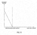
- FIG. 10 illustrates a graph used for the process of Step S91 in FIG. 9 .
- This graph is stored in the control unit 13.
- This graph indicates a recovery amount of the water recovered in the fuel tank 2 by the collector 16 corresponding to the moisture content obtained by the detector 2A.
- a horizontal axis indicates the moisture content of the water-containing fuel, and a vertical axis indicates the recovery amount of the water returned to the fuel tank 2.
- the specified moisture content is indicated.
- a recovery process is performed to recover the water separated by the separator 3 in the fuel tank 2.
- the control unit 13 controls the pump of the collector 16 such that, as the moisture content decreases, the recovery amount increases. Then, the moisture content of the water-containing fuel in the fuel tank 2 can be mostly equalized to the specified moisture content.
- FIG. 11 is a drawing illustrating a flowchart when the recovery control process of the embodiment is performed with the separation control process of the first embodiment.
- the flowchart illustrated in FIG. 11 is different from the flowchart of the first embodiment illustrated in FIG. 3 in that a determination process of Step S111 and a recovery process of Step S91 are added. It should be noted that, in Step S91, a process identical to the recovery process in the recovery control process illustrated in FIG. 9 is performed.
- Step Sill whether or not the moisture content of the water-containing fuel detected by the detector 2A is equal to or more than the specified moisture content is determined.
- the moisture content is equal to or more than the specified moisture content (S111: Yes)
- the moisture content is below the specified moisture content (S111: No)
- it is determined that the water contained in the water-containing fuel needs to be recovered in the fuel tank 2 and the process proceeds to the recovery control process of Step S91.
- the separation control process is performed, and on the other hand, when the moisture content of the water-containing fuel is lower than the specified moisture content, the recovery control process is performed. Therefore, in any case, the moisture content of the water-containing fuel stored in the fuel tank 2 can be mostly equalized to the specified moisture content.
- the fuel cell system 100 of the second embodiment provides the following effects.
- the water-containing fuel having a high fuel content is used for driving the fuel cell system 100.
- the anode gas is supplied to the fuel cell stack 1 by an amount exceeding a predetermined amount, thus possibly failing to appropriately control the power generation performance.
- the recovery of the water separated in the separator 3 in the fuel tank 2 ensures increasing the moisture content of the water-containing fuel in the fuel tank 2. Accordingly, the moisture content of the water-containing fuel used for driving the fuel cell system 100 does not fall to below the specified moisture content. Then, the power generation performance of the fuel cell stack 1 can be more appropriately reduced.
- the separation control process of the first embodiment may be combined with the recovery control process of this embodiment. Then, when the moisture content of the water-containing fuel is above the specified moisture content, the separation control process is performed, thus decreasing the moisture content of the water-containing fuel so as to become mostly the specified moisture content. On the other hand, when the moisture content of the water-containing fuel is below the specified moisture content, the recovery control process is performed, thus increasing the moisture content of the water-containing fuel so as to become mostly the specified moisture content. Accordingly, the moisture content of the water-containing fuel used for driving the fuel cell system 100 is mostly equalized to the specified moisture content, thus ensuring the appropriate electric generation in the fuel cell stack 1.
- the water-containing fuel where a part of the water is separated in the separator 3 is supplied to the burner 10, the catalyst combustor 11, and the discharged air combustor 12 via the fuel pump 4, this should not be construed in a limiting sense.
- a description will be given of an example where a part of the water-containing fuel after passing through the separator 3 is stored in a tank.
- FIG. 12 is a block diagram of a fuel cell system 100 of the third embodiment.
- the fuel cell system 100 illustrated in FIG. 12 is different from the fuel cell system 100 of the first embodiment illustrated in FIG. 1 in that passages 1201, 1202, and 1203, an activation fuel tank 17, and an activation pump 18 are added.
- the activation fuel tank 17 includes a residual sensor 17A that obtains a remaining amount of the fuel in the activation fuel tank 17.
- the passages 1201, 1202, and 1203 serve as activation fuel passages where the fuel for activation flows.
- the burner 10 is referred to as an activation buener in some cases.
- the water-containing fuel where a part of the water is separated in the separator 3 is stored in the activation fuel tank 17 from the fuel pump 4 via the passage 1201. Then, the water-containing fuel stored in the activation fuel tank 17 reaches the activation pump 18 via the passage 1202, and is supplied to the burner 10 via the passage 1203.
- a control processing in the fuel cell system 100 is illustrated in FIG. 13 .
- Step S131 the control unit 13 determines whether or not the fuel cell system 100 is in a cold start state.
- the cold start means that the fuel cell system 100 is activated in a low-temperature state in winter and similar situation.
- the water-containing fuel having a low moisture content compared with the ordinary moisture content is preferred to be used in the burner 10. This is because an ignition is less likely to occur in the burner 10 on the cold start.
- Step S131 the control unit 13 determines whether the temperature of the fuel cell stack 1 is equal to or less than a predetermined cold start determination temperature to determine whether or not in the cold start state.
- the control unit 13 determines it to be the cold start state (S131: Yes), and determines that it is necessary to cause the ignition in the burner 10 to easily occur, thus advancing the process to Step S132.
- Step S132 the control unit 13 controls the separator 3 so as to separate the water by a constant amount irrespective of the moisture content.
- the separator 3 is driven at a maximum separation capacity. Then, the water-containing fuel having the low moisture content is stored in the activation fuel tank 17 via the fuel pump 4. Therefore, on the cold start, the water-containing fuel having the low moisture content is supplied from the activation fuel tank 17 via the activation pump 18, thus causing the ignition in the burner 10 to easily occur.
- the control unit 13 determines it not to be the cold start state (S131: No), and determines that it is not necessary to cause the ignition in the burner 10 to easily occur, thus advancing the process to Step S133.
- Step S133 the control unit 13 determines whether or not the fuel cell system 100 is performing a stop control process. It should be noted that the stop control of the fuel cell system 100 is started from a re-pressing of a start button of the vehicle and a state where a battery, in which the electric power generated in the fuel cell stack 1 is stored, becomes full charge. Then, the stop control terminates at a timing where the cooling of the fuel cell system 100 completes and the controls of various configurations of the fuel cell system 100 complete.
- a system stop control as the stop control process of the fuel cell system 100 is a control executed while the system is stopped, and while the system is stopped means a time period from a start of the system stop control to a next system activation.
- the water-containing fuel having the low moisture content compared with the ordinary moisture content is preferred to be stored in the activation fuel tank 17. Then, even if the fuel is much evaporated than the water in the water-containing fuel in the activation fuel tank 17 before restart of the fuel cell system 100, the moisture content is morelikely to become lower than the specified moisture content. Therefore, on the restart of the fuel cell system 100, the water-containing fuel having the low moisture content is supplied from the activation fuel tank 17 via the activation pump 18, thus causing the ignition in the burner 10 to easily occur.
- Step S134 when the control unit 13 determines that the fuel cell system 100 is stopped (S133: Yes), it is determined that the water-containing fuel having a comparatively low moisture content needs to be stored in the activation fuel tank 17, and the process proceeds to Step S134.
- Step S134 it is determined whether or not the remaining amount of the water-containing fuel in the activation fuel tank 17 obtained by the residual sensor 17A is above a predetermined reference amount.
- the predetermined reference amount is configured to be greater than the amount of the water-containing fuel supplied to the burner 10 while the activation process of the fuel cell system 100 is performed.
- Step 135 the separator 3 and the fuel pump 4 are stopped. Then, the fuel cell system 100 is completely stopped.
- Step S31 and S32 are performed similarly to the first embodiment.
- the burner 10 is used mainly on the activation of the fuel cell system 100. Therefore, a valve and similar unit may be disposed between the separator 3 and the activation fuel tank 17 such that the valve is closed at the time other than the system activation. Then, such a water-containing fuel, which is generated while the fuel cell system 100 is in the usual operation and has the moisture content equal to the specified moisture content, can be prevented from being stored in the activation fuel tank 17. Accordingly, the moisture content of the water-containing fuel stored in the activation fuel tank 17 can be much lowered.
- the fuel cell system 100 of the third embodiment provides the following effects.
- the separator 3 on the activation of the fuel cell system 100, the separator 3 is driven by a predetermined driving force (for example, the maximum separation capacity) to generate the water-containing fuel where the moisture content is below the specified moisture content. Then, on the activation of the fuel cell system 100, the water-containing fuel having the low moisture content is supplied to the burner 10. Therefore, even in the case of the cold start of the fuel cell system 100, the burner 10 can be appropriately driven. Accordingly, a time period before heating the fuel cell stack 1 can be reduced, thus ensuring reducing a time period before the start of the electric generation in the fuel cell stack 1.
- a predetermined driving force for example, the maximum separation capacity
- the separator 3 is driven by the predetermined driving force to generate the water-containing fuel such that the moisture content is below the specified moisture content, and this water-containing fuel is stored in the activation fuel tank 17. This operation is performed until the water-containing fuel is stored in the activation fuel tank 17 by a predetermined amount. Then, when the fuel cell system 100 is completely stopped, the water-containing fuel having the moisture content below the specified moisture content is stored in the activation fuel tank 17 by the predetermined amount.
- the fuel cell system 100 even if the fuel is evaporated in the activation fuel tank 17 before the fuel cell system 100 is reactivated, it does not occur that the moisture content of the water-containing fuel in the activation fuel tank 17 significantly exceeds the specified moisture content. Accordingly, when the fuel cell system 100 is reactivated, the water-containing fuel having the moisture content nearly equal to the specified moisture content is supplied to the burner 10 to appropriately drive the burner 10, thus the decrease of the power generation performance of the fuel cell stack 1 can be reduced.
- separator 3 is disposed between the fuel pump 4 and the evaporator 5 in the first embodiment, this should not be construed in a limiting sense.
- the separator 3 may be disposed so as to be adjacent to the evaporator 5.
- FIG. 14 is a block diagram of a fuel cell system 100 of a fourth embodiment.
- the fuel cell system 100 illustrated in FIG. 14 is different from the fuel cell system 100 of the first embodiment illustrated in FIG. 1 in that the separator 3 is disposed adjacent to the evaporator 5.
- FIG. 15 illustrates an exemplary detailed configuration of the separator 3 and the evaporator 5.
- the evaporator 5 is configured as a flow passage where the water-containing fuel flows, and a water-containing fuel 51 is warmed to be evaporated by a heat of a discharged air from the discharged air combustor 12.
- the separator 3 On a downstream end of the flow passage of the evaporator 5, the separator 3 is disposed.
- the separator 3 is constituted of a drain 39 that discharges the water-containing fuel 51 on the flow passage of the evaporator 5 to the outside of the fuel cell system 100, and a valve 40 configured to open/close the drain 39.
- the drain 39 disposed on the downstream side of the evaporator 5 can discharge the water-containing fuel having the high moisture content to the outside of the fuel cell system 100.
- the reformer 7 since an evaporation speed of the water-containing fuel is appropriately controlled in the evaporator 5, the reformer 7 is supplied with the fuel gas by an appropriate amount. Then, the anode gas is sufficiently generated in the reformer 7, thus reducing the decrease of the power generation performance of the fuel cell stack 1. It should be noted that the control unit 13 operates the valve 40 corresponding to the moisture content of the water-containing fuel in the fuel tank 2 detected by the detector 2A.
- an opening amount of the valve 40 is increased. Then, since a time period where the water-containing fuel stays on the upstream side of the evaporator 5 becomes longer, much more fuel is evaporated to ensure increasing the fuel gas generation. On the other hand, when the moisture content of the water-containing fuel in the fuel tank 2 is low, the opening amount of the valve 40 is decreased. Then, since the time period where the water-containing fuel stays on the upstream side of the evaporator 5 becomes shorter, the amount of the fuel gas generated by evaporation is decreased to ensure reducing the fuel gas generation. Thus, the amount of the fuel gas generated in the evaporator 5 is controlled.
- the fuel cell system 100 of the fourth embodiment provides the following effects.
- the separator 3 is disposed adjacent to the evaporator 5. Then, the moisture content adjusted in the more downstream side of the fuel supply system ensures more appropriate adjustment of the supply amount of the anode gas to the fuel cell stack 1, compared with the case where the separator 3 is disposed between the fuel pump 4 and the fuel tank 2 as the first embodiment. Furthermore, the need for the configuration such as the water separation membrane 34 and the decompression pump 38 as the first embodiment is eliminated, thus ensuring simplification of the configuration.
Landscapes
- Life Sciences & Earth Sciences (AREA)
- Engineering & Computer Science (AREA)
- Manufacturing & Machinery (AREA)
- Sustainable Development (AREA)
- Sustainable Energy (AREA)
- Chemical & Material Sciences (AREA)
- Chemical Kinetics & Catalysis (AREA)
- Electrochemistry (AREA)
- General Chemical & Material Sciences (AREA)
- Fuel Cell (AREA)
- Electric Propulsion And Braking For Vehicles (AREA)
Abstract
Description
- The present invention relates to a fuel cell system and a control method for the fuel cell system.
- There has been known a Solid Oxide Fuel Cell (SOFC) where anode gas is supplied to one side and cathode gas (air and similar gas) is supplied to the other side to be configured to operate at a relatively high temperature. This SOFC uses a water-containing fuel such as water-containing ethanol. Since the fuel contained in such a water-containing fuel is easily evaporated compared with water, a moisture content of the water-containing fuel increases in a fuel tank. Using such a water-containing fuel having the high moisture content possibly reduces a power generation performance of the fuel cell.
- Therefore, for example,
JP2010-190210A - However, in the technique disclosed in
JP2010-190210A - It is an object of the present invention to provide a fuel cell system configured to appropriately adjust a moisture content of a water-containing fuel used for driving a fuel cell.
- According to one embodiment of this invention, a fuel cell system including: a solid oxide type fuel cell that is supplied with an anode gas and a cathode gas to generate an electric power; a fuel tank that stores a water-containing fuel containing water; a fuel supply passage that couples the fuel cell to the fuel tank; a reformer disposed on the fuel supply passage, the reformer reforming the water-containing fuel into the anode gas; a separator disposed on the fuel supply passage in an upstream side with respect to the reformer, the separator separating the water contained in the water-containing fuel; a detector disposed in the upstream side with respect to the reformer, the detector detecting or estimating a moisture content contained in the water-containing fuel; and a control unit that controls the separator. The control unit controls the separator on the basis of the moisture content detected or estimated by the detector.
-
-
FIG. 1 is a block diagram of a fuel cell system of a first embodiment. -
FIG. 2 is a block diagram of a separator. -
FIG. 3 is a flowchart illustrating a separation control process. -
FIG. 4 is a graph illustrating a separation amount in the separation control process. -
FIG. 5 is a flowchart illustrating another separation control process. -
FIG. 6 is a graph illustrating a control amount by the separator in the other separation control process. -
FIG. 7 is a flowchart illustrating yet another separation control process. -
FIG. 8 is a block diagram of a fuel cell system of a second embodiment. -
FIG. 9 is a flowchart illustrating a recovery control process. -
FIG. 10 is a graph illustrating a recovery amount of water in the recovery control process. -
FIG. 11 is a flowchart illustrating a control process for performing the separation and the recovery. -
FIG. 12 is a block diagram of a fuel cell system of a third embodiment. -
FIG. 13 is a flowchart illustrating a separation control process. -
FIG. 14 is a block diagram of a fuel cell system of a fourth embodiment. -
FIG. 15 is a block diagram of another separator. - The following describes the embodiments of the present invention with reference to the attached drawings.
-
FIG. 1 is a block diagram illustrating a main configuration of a Solid Oxide Fuel Cell (SOFC) system in a first embodiment. This system generates electric powers used for driving an electric vehicle and similar purpose. - In a fuel cell stack 1 as the SOFC, cells are stacked, and the cell is constituted by sandwiching an electrolyte layer made of a solid oxide such as ceramic between an anode electrode (a fuel electrode) to which an anode gas (a fuel gas) as a fuel is supplied and a cathode pole (an air electrode) to which an air containing oxygen is supplied as a cathode gas (an oxidizing gas). In the fuel cell stack 1, the fuel such as hydrogen contained in the anode gas is reacted with oxygen in the cathode gas to generate the electric power, and an anode gas after the reaction (an anode off-gas) and a cathode gas after the reaction (a cathode off-gas) are discharged.
- A solid oxide fuel cell system (hereinafter referred to as a fuel cell system 100) that includes the fuel cell stack 1 includes a fuel supply system that supplies the anode gas to the fuel cell stack 1, an air supply system that supplies the cathode gas to the fuel cell stack 1, and an air discharge system that discharges the anode off-gas and the cathode off-gas to an outside of the
fuel cell system 100. - The fuel supply system includes a
fuel tank 2, aseparator 3, afuel pump 4, anevaporator 5, araw material heater 6, areformer 7, and similar unit. The air supply system includes acathode compressor 8, anair heat exchanger 9, aburner 10, acatalyst combustor 11, and similar unit. The air discharge system includes a dischargedair combustor 12 and similar unit. Thefuel cell system 100 includes acontrol unit 13 that controls operations of the entire system. Thecontrol unit 13 controls various kinds of equipment in thefuel cell system 100 to adjust the moisture content of the water-containing fuel used for driving thefuel cell system 100. - The following describes each system in detail. First, the fuel supply system will be described in detail.
- In the fuel supply system, the
separator 3, thefuel pump 4, theevaporator 5, theraw material heater 6, and thereformer 7 are disposed on an anode supply passage from thefuel tank 2 to the fuel cell stack 1. - The water-containing fuel stored in the
fuel tank 2 is supplied to theseparator 3 passing through apassage 101. For example, the water-containing fuel is a water-containing fuel that contains a water content such as a water-containing ethanol. Thefuel tank 2 internally includes adetector 2A that obtains the moisture content of the water-containing fuel stored in thefuel tank 2. Thedetector 2A uses a difference in dielectric constant between the fuel (ethanol) and water, thus detecting or estimating the moisture content of the water-containing fuel. It should be noted that the water-containing fuel may include a hydrocarbon fuel other than ethanol. - The
separator 3 separates a part of the water contained in the water-containing fuel. Theseparator 3 is configured such that a separation amount of the water from the water-containing fuel increases as an operation amount of theseparator 3 increases. It should be noted that a detailed configuration of theseparator 3 will be described later by referring toFIG. 3 . Thepassage 101 includes atemperature sensor 14 and aflow rate sensor 15. Thetemperature sensor 14 obtains a temperature of the water-containing fuel supplied to theseparator 3, and theflow rate sensor 15 obtains a flow rate of the water-containing fuel supplied to theseparator 3. - The water-containing fuel where a part of the water is separated in the
separator 3 reaches thefuel pump 4 passing through apassage 102, and is sent out to apassage 103 from thefuel pump 4. Thepassage 103 branches intopassages passage 103 is supplied to theevaporator 5 via thepassage 104, and supplied to the dischargedair combustor 12 via thepassage 105. Thepassage 106 further branches intopassages passage 106 is supplied to theburner 10 via thepassage 107, and supplied to thecatalyst combustor 11 via thepassage 108. - The
evaporator 5 uses a heat of a discharged gas from the dischargedair combustor 12 to evaporate the water-containing fuel as a liquid, thus generating a fuel gas. The fuel gas generated by theevaporator 5 is supplied to theraw material heater 6 via apassage 109. - The
raw material heater 6 is disposed adjacent to the dischargedair combustor 12. Theraw material heater 6 uses the heat generation in the dischargedair combustor 12 to further heat the fuel gas to a temperature so as to be reformable in thereformer 7. Then, the fuel gas heated in theraw material heater 6 is supplied to thereformer 7 via apassage 110. - The fuel gas supplied to the
reformer 7 is reformed into an anode gas through a catalytic reaction. This anode gas is supplied to the anode electrode of the fuel cell stack 1 from thereformer 7 via apassage 111. For example, when the water-containing fuel is the water-containing ethanol, the water-containing fuel is reformed into the anode gas that contains methane, hydrogen, carbon monoxide, and similar material. - Next, a description will be given of the air supply system in detail.
- In the air supply system, an air as a cathode gas taken in from outside is taken into the
fuel cell system 100 by thecathode compressor 8, and reaches theair heat exchanger 9 at first via apassage 112. - The
air heat exchanger 9 uses the heat of the discharged gas from the dischargedair combustor 12 to heat the cathode gas. The cathode gas heated by theair heat exchanger 9 is supplied to theburner 10 via apassage 113, and subsequently, supplied to thecatalyst combustor 11 via apassage 114. Theburner 10 and thecatalyst combustor 11 are activated mainly in a system activation process in thefuel cell system 100. It should be noted that the system activation process is a process, for example, performed from when a pressing down of a start switch of a vehicle that includes afuel cell system 100 to start the operation of thefuel cell system 100 until when the fuel cell stack 1 becomes to stably perform the electric generation. - On the activation of the
fuel cell system 100, in theburner 10, the cathode gas supplied from thecathode compressor 8 is mixed with the water-containing fuel supplied from thefuel pump 4 via thepassages burner 10 ignites the mixed gas to form a preheating burner for heating thecatalyst combustor 11. - The catalyst combustor 11 is a unit that internally includes a catalyst, and uses this catalyst to generate a combustion gas having a high temperature. On the activation of the system, the cathode gas from the
cathode compressor 8 and the water-containing fuel from thefuel pump 4 are supplied to thecatalyst combustor 11. The catalyst in thecatalyst combustor 11 has been heated by the preheating burner, and the cathode gas and the fuel contained in the water-containing fuel are combusted on the heated catalyst, thus generating a combustion gas. It should be noted that the combustion gases discharged from theburner 10 and thecatalyst combustor 11 are inert gases containing little oxygen and having high temperatures. - Thus, on the activation of the
fuel cell system 100, the fuel cell stack 1 is supplied with the inert gas warmed by thecatalyst combustor 11 via apassage 115 so as to have the temperature to ensure the fuel cell stack 1 to perform the electric generation. Then, when the fuel cell stack 1 becomes to be in the temperature for appropriately performing the electric generation and the system activation process terminates, combustion reactions in theburner 10 and thecatalyst combustor 11 terminate and the fuel cell stack 1 is supplied with the cathode gas heated by theair heat exchanger 9. - Thus, the fuel cell stack 1 is supplied with the anode gas from the fuel supply system, and is supplied with the cathode gas from the air supply system. Then, in the fuel cell stack 1, the anode gas reacts with the cathode gas to generate the electric power, and an anode off-gas and a cathode off-gas are discharged outside the
fuel cell system 100 via the air discharge system. - Next, a description will be given of the air discharge system in detail.
- The fuel cell stack 1 discharges the anode off-gas from a
passage 116, and discharges the cathode off-gas from apassage 117. The anode off-gas and the cathode off-gas are combusted in the dischargedair combustor 12 through an oxidation catalytic reaction, and discharged to apassage 118 as a discharged gas. The heat generated in accordance with the combustion is transmitted to theraw material heater 6 adjacent to the dischargedair combustor 12. The discharged gas reaches theevaporator 5 via thepassage 118, and subsequently, reaches theair heat exchanger 9 passing via apassage 119. Then, the discharged gas is finally discharged outside thefuel cell system 100 via apassage 120. - The discharged
air combustor 12 is constituted of a ceramic material such as alumina, and mixes the anode off-gas with the cathode off-gas to combust the mixed gas through an oxidation catalyst, thus generating the discharged gas containing carbon dioxide and water as main components. The dischargedair combustor 12 is configured to be supplied with the water-containing fuel via thepassage 105. Adjusting a supply amount of the water-containing fuel supplied to the dischargedair combustor 12 ensures controlling a catalytic combustion reaction in the dischargedair combustor 12. - It should be noted that the
control unit 13 controls a valve and similar part in each configuration and each system of thefuel cell system 100 to control the entirefuel cell system 100. It should be noted that thecontrol unit 13 is configured of a microcomputer that includes a central processing unit (CPU), a read-only memory (ROM), a random access memory (RAM), and an input/output interface (an I/O interface). - Here, a detailed configuration of the
separator 3 will be described by referring toFIG. 2 . - By referring to
FIG. 2 , theseparator 3 includes afuel container 31, a coolingcontainer 32, and apipe 33 that couples thefuel container 31 to the coolingcontainer 32. Thefuel container 31 internally includes awater separation membrane 34 to provide afuel chamber 35 where the water-containing fuel flows and anatmosphere chamber 36 where the water-containing fuel does not flow but an atmosphere exists. It should be noted that, specifically, thewater separation membrane 34 is constituted of, for example, a polymer membrane without holes and a ceramic that has pores. Thepipe 33 is coupled to theatmosphere chamber 36 in thefuel container 31. The coolingcontainer 32 is configured to be cooled by being disposed in awater tank 37 and to be decompressed by adecompression pump 38. - When the
decompression pump 38 is driven, air pressures in the coolingcontainer 32, thepipe 33, and theatmosphere chamber 36 of thefuel container 31 decrease. In such a state, in thefuel container 31, a part of the water content contained in the water-containing fuel that resides on thefuel chamber 35 becomes water vapor to be transmitted through thewater separation membrane 34, and reaches theatmosphere chamber 36. Then, this water vapor is liquefied again in the coolingcontainer 32 cooled by water in thewater tank 37. It should be noted that the water liquefied in the coolingcontainer 32 is discharged outside thefuel cell system 100 at a predetermined timing. The coolingcontainer 32 includes a drain communicated with the outside of thefuel cell system 100, and the liquefied water is discharged outside thefuel cell system 100 via this drain as necessary. Thecontrol unit 13 controls the driving of thedecompression pump 38 so as to obtain a transmembrane pressure as a difference in pressure between thefuel chamber 35 and theatmosphere chamber 36, which are mutually adjacent via thewater separation membrane 34, in a desired magnitude, thus ensuring controlling the moisture amount separated from the water-containing fuel. - Next, by referring to
FIG. 3 , a description will be given of a separation control process performed by thecontrol unit 13 of the embodiment.FIG. 3 illustrates an exemplary separation control process for separating a part of the water contained in water-containing fuel. This process is configured to be repeatedly performed at predetermined intervals from the activation to the termination of thefuel cell system 100. - In Step S31 (a detection step), the
detector 2A disposed in thefuel tank 2 obtains the moisture content of the water-containing fuel stored in thefuel tank 2. - Then, in Step S32 (a separation step), the
control unit 13 controls theseparator 3 corresponding to the moisture content obtained by thedetector 2A. Thus, the water-containing fuel sent out from theseparator 3 by thefuel pump 4 has a desired moisture content. -
FIG. 4 illustrates a graph used for a process of Step S32 inFIG. 3 . This graph is stored in thecontrol unit 13. This graph indicates a separation amount of the water separated by theseparator 3 corresponding to the moisture content obtained by thedetector 2A. A horizontal axis indicates the moisture content of the water-containing fuel, and a vertical axis indicates the separation amount of the water in theseparator 3. The moisture content of the water-containing fuel where the electric generation by the fuel cell stack 1 is appropriately performed is indicated as a specified moisture content. - When the moisture content of the water-containing fuel is below the specified moisture content, the separation control process on the water by the
separator 3 is not performed. On the other hand, when the moisture content is above the specified moisture content, the separation control process on the water by theseparator 3 is performed. Specifically, theseparator 3 is controlled such that, as the moisture content increases, the separation amount increases. Then, the moisture content of the water-containing fuel supplied to the fuel supply system from theseparator 3 can be mostly equalized to the specified moisture content. - It should be noted that when the
separator 3 has a configuration that includes thewater separation membrane 34 as illustrated inFIG. 2 , the separation amount of the water separated by theseparator 3 is determined corresponding to the transmembrane pressure. Therefore, thecontrol unit 13 decides a control amount (a drive electric power) of thedecompression pump 38 of theseparator 3 such that the separation amount of the water in theseparator 3 has the desired value, thus controlling the transmembrane pressure. Thecontrol unit 13 may control thedecompression pump 38 by using a graph that indicates the transmembrane pressure on the vertical axis instead of the graph inFIG. 4 . - As a modification, another example of the separation control process is illustrated in
FIG. 5 . - The separation control process illustrated in
FIG. 5 is different from the separation control process illustrated inFIG. 3 in that a process of Step S51 is added between Step S31 and S32. - In Step S51, the
temperature sensor 14 disposed on thepassage 101 between thefuel tank 2 and theseparator 3 obtains a temperature of the water-containing fuel supplied to theseparator 3. Here, it has been known that theseparator 3 has a water separation capacity that differs depending on the temperature of the water-containing fuel. For example, when theseparator 3 has the configuration that includes thewater separation membrane 34 as illustrated inFIG. 2 , the separation amount differs depending on the temperature of the water-containing fuel even in an identical transmembrane pressure. Specifically, as the temperature increases, the separation amount increases even in an identical transmembrane pressure, thus the water is separatable by a desired amount even if the transmembrane pressure is low. - Therefore, the
control unit 13 preliminarily stores a graph as illustrated inFIG. 6 . - In the graph in
FIG. 6 , a vertical axis indicates the temperature of the water-containing fuel, and a horizontal axis indicates the moisture content of the water-containing fuel. Furthermore, the graph indicates the desired transmembrane pressures in theseparator 3 corresponding to the temperature and the moisture content of the water-containing fuel. - The
control unit 13 drives thedecompression pump 38 so as to have the transmembrane pressure indicated on a position inFIG. 6 determined corresponding to the temperature of the water-containing fuel obtained by thetemperature sensor 14 and the moisture content of the water-containing fuel obtained by thedetector 2A. It should be noted that when the transmembrane pressure that corresponds to the position determined corresponding to the temperature and the moisture content is not indicated inFIG. 6 , thecontrol unit 13 determines the transmembrane pressure by a proportional distribution method and similar method. Thus, since thecontrol unit 13 corrects the operation amount of theseparator 3 corresponding to the temperature of the water-containing fuel obtained by thetemperature sensor 14, the water can be accurately removed from the water-containing fuel by the desired amount. - As a further modification, another example of the separation control process is illustrated in
FIG. 7 . - The separation control process illustrated in
FIG. 7 is different from the separation control process illustrated inFIG. 5 in that a process of Step S71 is added between Steps S51 and S32. - In Step S71, the
flow rate sensor 15 disposed on thepassage 101 between thefuel tank 2 and theseparator 3 obtains the flow rate of the water-containing fuel that flows in theseparator 3. Here, it has been known that theseparator 3 has the separation capacity that differs also depending on the flow rate of the water-containing fuel that flows in. For example, the separation amount differs depending on the flow rate even in the identical transmembrane pressure. Specifically, as the flow rate increases, the separation amount decreases. - Therefore, the
control unit 13 preliminarily stores a plurality of graphs that indicate the relations between the temperature and separation amount, and the transmembrane pressure, as illustrated inFIG. 6 , corresponding to the flow rate of the water-containing fuel that flows in theseparator 3. Specifically, in the graphs, in the identical temperature and the identical moisture content of the water-containing fuel, the transmembrane pressure increases as the flow rate increases. Thecontrol unit 13 selects the graph that corresponds to the flow rate of the water-containing fuel obtained by theflow rate sensor 15, and uses the selected graph to obtain the transmembrane pressure that corresponds to the temperature and the moisture content of the water-containing fuel. Then, thecontrol unit 13 drives thedecompression pump 38 so as to have the obtained transmembrane pressure. Thus, since thecontrol unit 13 corrects the operation amount of theseparator 3 corresponding to the flow rate of the water-containing fuel obtained by theflow rate sensor 15, the water can be accurately removed from the water-containing fuel by the desired amount. - It should be noted that, while the
detector 2A is disposed in thefuel tank 2 in this embodiment, this should not be construed in a limiting sense. Thedetector 2A may be disposed, namely, on thepassages evaporator 5 on the anode supply passage. In a case of a configuration where thefuel cell system 100 does not include theevaporator 5 and directly reforms the water-containing fuel into the anode gas in thereformer 7, thedetector 2A is only necessary to be disposed on an upstream side of thereformer 7. Thus, since the moisture content of the water-containing fuel to be reformed into the anode gas is adjusted corresponding to the moisture content obtained by thedetector 2A, the anode gas used for the electric generation by the fuel cell stack 1 can be appropriately generated. - The
fuel cell system 100 of the first embodiment provides the following effects. - In the water-containing fuel stored in the
fuel tank 2, the fuel (ethanol) easily evaporates compared with the water. Therefore, the water-containing fuel stored in thefuel tank 2 over a long period of time has a decreased fuel content and an increased moisture content. The water-containing fuel stored in thefuel tank 2 is reformed into the anode gas passing through a fuel supply passage (thepassages fuel tank 2 over a long period of time is used, the increased moisture content possibly causes the anode gas not to be appropriately supplied to the fuel cell stack 1 so as to reduce a power generation performance. - Therefore, according to the
fuel cell system 100 of the first embodiment, thedetector 2A that detects the moisture content of the water-containing fuel stored in thefuel tank 2, and theseparator 3 that separates the water contained in the water-containing fuel are disposed. Then, thecontrol unit 13 controls the separation amount of the water in theseparator 3 corresponding to the moisture content detected by thedetector 2A. Then, since the moisture content contained in the water-containing fuel decreases, the evaporation of the water-containing fuel into the fuel gas in theevaporator 5 and the reformation of the fuel gas into the anode gas in thereformer 7 are appropriately performed. Accordingly, the fuel cell stack 1 is appropriately supplied with the anode gas, thus ensuring reducing the decrease of the power generation performance in the fuel cell stack 1. - According to the
fuel cell system 100 of the first embodiment, as illustrated inFIG. 2 , when the moisture content detected by thedetector 2A is above a specified amount (the specified moisture content), theseparator 3 is controlled such that the more the moisture content increases, the more the water is separated. Then, since the moisture content of the water-containing fuel supplied from theseparator 3 does not exceed the specified amount, the fuel cell stack 1 is appropriately supplied with the anode gas, thus ensuring reducing degradation of the power generation performance. Theseparator 3 operates only when the moisture content of the water-containing fuel is above the specified amount, and does not operate when the moisture content of the water-containing fuel is below the specified amount. Then, an unnecessary separation control process by theseparator 3 can be reduced. - According to the
fuel cell system 100 of the first embodiment, thetemperature sensor 14 that obtains the temperature of the water-containing fuel supplied to theseparator 3 is disposed. Here, it has been known that the separation amount of the water in theseparator 3 differs depending on the temperature of the water-containing fuel. Therefore, thecontrol unit 13 controls theseparator 3 also corresponding to the temperature of the water-containing fuel obtained by thetemperature sensor 14 in addition to the moisture content of the water-containing fuel. Specifically, as the temperature of the water-containing fuel increases, the drive electric power of theseparator 3 is decreased. For example, when theseparator 3 has the configuration that includes thewater separation membrane 34 and thedecompression pump 38 as illustrated inFIG. 2 , thedecompression pump 38 is controlled such that, as the temperature of the water-containing fuel increases, the transmembrane pressure decreases. Then, since an accuracy of the separation amount of the water in theseparator 3 increases, the water can be separated by the desired amount, thus ensuring reducing the decrease of the power generation performance in the fuel cell stack 1. - According to the
fuel cell system 100 of the first embodiment, theflow rate sensor 15 that obtains the supply amount of the water-containing fuel supplied to theseparator 3 is disposed. Here, it has been known that the separation amount of the water in theseparator 3 differs depending on the flow rate of the water-containing fuel. Therefore, thecontrol unit 13 controls theseparator 3 further corresponding to the flow rate of the water-containing fuel obtained by theflow rate sensor 15. Specifically, as the flow rate of the water-containing fuel increases, the drive electric power of theseparator 3 is increased. For example, when theseparator 3 has the configuration that includes thewater separation membrane 34 and thedecompression pump 38 as illustrated inFIG. 2 , thedecompression pump 38 is controlled such that, as the flow rate of the water-containing fuel increases, the transmembrane pressure increases. Then, since the accuracy of the separation amount of the water in theseparator 3 further increases, the water can be separated by the desired amount, thus ensuring reducing the decrease of the power generation performance in the fuel cell stack 1. - According to the
fuel cell system 100 of the first embodiment, theseparator 3 includes thewater separation membrane 34 to provide thefuel chamber 35 and theatmosphere chamber 36. When theatmosphere chamber 36 is decompressed to increase the transmembrane pressure as the difference between the pressure of theatmosphere chamber 36 and the pressure of thefuel chamber 35, a part of the water content contained in the water-containing fuel that resides on thefuel chamber 35 becomes water vapor to be transmitted through thewater separation membrane 34, and reaches theatmosphere chamber 36. Accordingly, thecontrol unit 13 controls the transmembrane pressure, thus ensuring accurately controlling the separation amount of the water in theseparator 3. - According to the
fuel cell system 100 of the first embodiment, the coolingcontainer 32 coupled to theatmosphere chamber 36 of thefuel container 31 in theseparator 3 via thepipe 33 is disposed, and thedecompression pump 38 is disposed in the coolingcontainer 32. Therefore, thecontrol unit 13 drivingly controls thedecompression pump 38 so as to have the desired transmembrane pressure. Then, the transmembrane pressure is controlled, thus ensuring accurately controlling the separation amount of the water in theseparator 3. - While, in the first embodiment, the water separated in the
separator 3 is discharged outside thefuel cell system 100, this should not be construed in a limiting sense. The water separated in theseparator 3 may be used again in thefuel cell system 100. -
FIG. 8 is a block diagram of afuel cell system 100 of a second embodiment. Thefuel cell system 100 illustrated inFIG. 8 is different from thefuel cell system 100 in the first embodiment illustrated inFIG. 1 in thatpassages collector 16 are disposed. - The
collector 16 includes a tank and a pump. The water separated in theseparator 3 reaches thecollector 16 via thepassage 801, and is stored in the tank in thecollector 16. Then, the pump (a recovery pump) of thecollector 16 supplies the water in the tank to thefuel tank 2 via thepassage 802. Accordingly, thepassages fuel tank 2. -
FIG. 9 is a flowchart illustrating a recovery control process performed by thecontrol unit 13. - The recovery control process illustrated in
FIG. 9 is different from the separation control process in the first embodiment illustrated inFIG. 3 in that a process of Step S91 is performed instead of Step S32. - In Step S91, the pump of the
collector 16 is driven corresponding to the moisture content of the water-containing fuel detected by thedetector 2A, thus the water separated in theseparator 3 is recovered in thefuel tank 2 via thepassages -
FIG. 10 illustrates a graph used for the process of Step S91 inFIG. 9 . This graph is stored in thecontrol unit 13. This graph indicates a recovery amount of the water recovered in thefuel tank 2 by thecollector 16 corresponding to the moisture content obtained by thedetector 2A. A horizontal axis indicates the moisture content of the water-containing fuel, and a vertical axis indicates the recovery amount of the water returned to thefuel tank 2. Similarly toFIG. 4 , the specified moisture content is indicated. - When the moisture content of the water-containing fuel is below the specified moisture content, a recovery process is performed to recover the water separated by the
separator 3 in thefuel tank 2. Thecontrol unit 13 controls the pump of thecollector 16 such that, as the moisture content decreases, the recovery amount increases. Then, the moisture content of the water-containing fuel in thefuel tank 2 can be mostly equalized to the specified moisture content. -
FIG. 11 is a drawing illustrating a flowchart when the recovery control process of the embodiment is performed with the separation control process of the first embodiment. The flowchart illustrated inFIG. 11 is different from the flowchart of the first embodiment illustrated inFIG. 3 in that a determination process of Step S111 and a recovery process of Step S91 are added. It should be noted that, in Step S91, a process identical to the recovery process in the recovery control process illustrated inFIG. 9 is performed. - In Step Sill, whether or not the moisture content of the water-containing fuel detected by the
detector 2A is equal to or more than the specified moisture content is determined. When the moisture content is equal to or more than the specified moisture content (S111: Yes), it is determined that the water contained in the water-containing fuel needs to be separated, and the process proceeds to Step S32. On the other hand, when the moisture content is below the specified moisture content (S111: No), it is determined that the water contained in the water-containing fuel needs to be recovered in thefuel tank 2, and the process proceeds to the recovery control process of Step S91. - Then, when the moisture content of the water-containing fuel is higher than the specified moisture content, the separation control process is performed, and on the other hand, when the moisture content of the water-containing fuel is lower than the specified moisture content, the recovery control process is performed. Therefore, in any case, the moisture content of the water-containing fuel stored in the
fuel tank 2 can be mostly equalized to the specified moisture content. - The
fuel cell system 100 of the second embodiment provides the following effects. - When the moisture content of the water-containing fuel is below the specified moisture content, the water-containing fuel having a high fuel content is used for driving the
fuel cell system 100. In such a case, the anode gas is supplied to the fuel cell stack 1 by an amount exceeding a predetermined amount, thus possibly failing to appropriately control the power generation performance. - Therefore, the recovery of the water separated in the
separator 3 in thefuel tank 2 ensures increasing the moisture content of the water-containing fuel in thefuel tank 2. Accordingly, the moisture content of the water-containing fuel used for driving thefuel cell system 100 does not fall to below the specified moisture content. Then, the power generation performance of the fuel cell stack 1 can be more appropriately reduced. - Furthermore, as illustrated in
FIG. 11 , the separation control process of the first embodiment may be combined with the recovery control process of this embodiment. Then, when the moisture content of the water-containing fuel is above the specified moisture content, the separation control process is performed, thus decreasing the moisture content of the water-containing fuel so as to become mostly the specified moisture content. On the other hand, when the moisture content of the water-containing fuel is below the specified moisture content, the recovery control process is performed, thus increasing the moisture content of the water-containing fuel so as to become mostly the specified moisture content. Accordingly, the moisture content of the water-containing fuel used for driving thefuel cell system 100 is mostly equalized to the specified moisture content, thus ensuring the appropriate electric generation in the fuel cell stack 1. - While, in the first embodiment, the water-containing fuel where a part of the water is separated in the
separator 3 is supplied to theburner 10, thecatalyst combustor 11, and the dischargedair combustor 12 via thefuel pump 4, this should not be construed in a limiting sense. In a third embodiment, a description will be given of an example where a part of the water-containing fuel after passing through theseparator 3 is stored in a tank. -
FIG. 12 is a block diagram of afuel cell system 100 of the third embodiment. Thefuel cell system 100 illustrated inFIG. 12 is different from thefuel cell system 100 of the first embodiment illustrated inFIG. 1 in thatpassages activation fuel tank 17, and an activation pump 18 are added. It should be noted that theactivation fuel tank 17 includes aresidual sensor 17A that obtains a remaining amount of the fuel in theactivation fuel tank 17. Thepassages burner 10 is referred to as an activation buener in some cases. - The water-containing fuel where a part of the water is separated in the
separator 3 is stored in theactivation fuel tank 17 from thefuel pump 4 via thepassage 1201. Then, the water-containing fuel stored in theactivation fuel tank 17 reaches the activation pump 18 via thepassage 1202, and is supplied to theburner 10 via thepassage 1203. - A control processing in the
fuel cell system 100 is illustrated inFIG. 13 . - First, in Step S131, the
control unit 13 determines whether or not thefuel cell system 100 is in a cold start state. The cold start means that thefuel cell system 100 is activated in a low-temperature state in winter and similar situation. When in the cold start state, the water-containing fuel having a low moisture content compared with the ordinary moisture content is preferred to be used in theburner 10. This is because an ignition is less likely to occur in theburner 10 on the cold start. - Therefore, in Step S131, the
control unit 13 determines whether the temperature of the fuel cell stack 1 is equal to or less than a predetermined cold start determination temperature to determine whether or not in the cold start state. - When the temperature of the fuel cell stack 1 is equal to or less than the cold start determination temperature, the
control unit 13 determines it to be the cold start state (S131: Yes), and determines that it is necessary to cause the ignition in theburner 10 to easily occur, thus advancing the process to Step S132. - In Step S132, the
control unit 13 controls theseparator 3 so as to separate the water by a constant amount irrespective of the moisture content. For example, theseparator 3 is driven at a maximum separation capacity. Then, the water-containing fuel having the low moisture content is stored in theactivation fuel tank 17 via thefuel pump 4. Therefore, on the cold start, the water-containing fuel having the low moisture content is supplied from theactivation fuel tank 17 via the activation pump 18, thus causing the ignition in theburner 10 to easily occur. - On the other hand, when the temperature of the fuel cell stack 1 is above the cold start determination temperature, the
control unit 13 determines it not to be the cold start state (S131: No), and determines that it is not necessary to cause the ignition in theburner 10 to easily occur, thus advancing the process to Step S133. - In Step S133, the
control unit 13 determines whether or not thefuel cell system 100 is performing a stop control process. It should be noted that the stop control of thefuel cell system 100 is started from a re-pressing of a start button of the vehicle and a state where a battery, in which the electric power generated in the fuel cell stack 1 is stored, becomes full charge. Then, the stop control terminates at a timing where the cooling of thefuel cell system 100 completes and the controls of various configurations of thefuel cell system 100 complete. A system stop control as the stop control process of thefuel cell system 100 is a control executed while the system is stopped, and while the system is stopped means a time period from a start of the system stop control to a next system activation. - Here, when the stop control process of the
fuel cell system 100 completes, the water-containing fuel having the low moisture content compared with the ordinary moisture content is preferred to be stored in theactivation fuel tank 17. Then, even if the fuel is much evaporated than the water in the water-containing fuel in theactivation fuel tank 17 before restart of thefuel cell system 100, the moisture content is morelikely to become lower than the specified moisture content. Therefore, on the restart of thefuel cell system 100, the water-containing fuel having the low moisture content is supplied from theactivation fuel tank 17 via the activation pump 18, thus causing the ignition in theburner 10 to easily occur. - Then, when the
control unit 13 determines that thefuel cell system 100 is stopped (S133: Yes), it is determined that the water-containing fuel having a comparatively low moisture content needs to be stored in theactivation fuel tank 17, and the process proceeds to Step S134. - In Step S134, it is determined whether or not the remaining amount of the water-containing fuel in the
activation fuel tank 17 obtained by theresidual sensor 17A is above a predetermined reference amount. Here, the predetermined reference amount is configured to be greater than the amount of the water-containing fuel supplied to theburner 10 while the activation process of thefuel cell system 100 is performed. - When the remaining amount of the water-containing fuel in the
activation fuel tank 17 is equal to or less than the predetermined reference amount (S134: No), it is determined that the water-containing fuel having the low moisture content needs to be further stored in theactivation fuel tank 17, and the process proceeds to Step S132. - On the other hand, when the remaining amount of the water-containing fuel in the
activation fuel tank 17 is above the predetermined reference amount (S134: Yes), it is determined that the water-containing fuel having the low moisture content does not need to be further stored in theactivation fuel tank 17, and the process proceeds to Step S135. - In
Step 135, theseparator 3 and thefuel pump 4 are stopped. Then, thefuel cell system 100 is completely stopped. - It should be noted that when the
fuel cell system 100 is not stopped (S133: No), the processes of Step S31 and S32 are performed similarly to the first embodiment. - It should be noted that the
burner 10 is used mainly on the activation of thefuel cell system 100. Therefore, a valve and similar unit may be disposed between theseparator 3 and theactivation fuel tank 17 such that the valve is closed at the time other than the system activation. Then, such a water-containing fuel, which is generated while thefuel cell system 100 is in the usual operation and has the moisture content equal to the specified moisture content, can be prevented from being stored in theactivation fuel tank 17. Accordingly, the moisture content of the water-containing fuel stored in theactivation fuel tank 17 can be much lowered. - The
fuel cell system 100 of the third embodiment provides the following effects. - According to the
fuel cell system 100 of the third embodiment, on the activation of thefuel cell system 100, theseparator 3 is driven by a predetermined driving force (for example, the maximum separation capacity) to generate the water-containing fuel where the moisture content is below the specified moisture content. Then, on the activation of thefuel cell system 100, the water-containing fuel having the low moisture content is supplied to theburner 10. Therefore, even in the case of the cold start of thefuel cell system 100, theburner 10 can be appropriately driven. Accordingly, a time period before heating the fuel cell stack 1 can be reduced, thus ensuring reducing a time period before the start of the electric generation in the fuel cell stack 1. - According to the
fuel cell system 100 of the third embodiment, while thefuel cell system 100 is stopped, theseparator 3 is driven by the predetermined driving force to generate the water-containing fuel such that the moisture content is below the specified moisture content, and this water-containing fuel is stored in theactivation fuel tank 17. This operation is performed until the water-containing fuel is stored in theactivation fuel tank 17 by a predetermined amount. Then, when thefuel cell system 100 is completely stopped, the water-containing fuel having the moisture content below the specified moisture content is stored in theactivation fuel tank 17 by the predetermined amount. Therefore, even if the fuel is evaporated in theactivation fuel tank 17 before thefuel cell system 100 is reactivated, it does not occur that the moisture content of the water-containing fuel in theactivation fuel tank 17 significantly exceeds the specified moisture content. Accordingly, when thefuel cell system 100 is reactivated, the water-containing fuel having the moisture content nearly equal to the specified moisture content is supplied to theburner 10 to appropriately drive theburner 10, thus the decrease of the power generation performance of the fuel cell stack 1 can be reduced. - While the
separator 3 is disposed between thefuel pump 4 and theevaporator 5 in the first embodiment, this should not be construed in a limiting sense. Theseparator 3 may be disposed so as to be adjacent to theevaporator 5. -
FIG. 14 is a block diagram of afuel cell system 100 of a fourth embodiment. Thefuel cell system 100 illustrated inFIG. 14 is different from thefuel cell system 100 of the first embodiment illustrated inFIG. 1 in that theseparator 3 is disposed adjacent to theevaporator 5. -
FIG. 15 illustrates an exemplary detailed configuration of theseparator 3 and theevaporator 5. - The
evaporator 5 is configured as a flow passage where the water-containing fuel flows, and a water-containingfuel 51 is warmed to be evaporated by a heat of a discharged air from the dischargedair combustor 12. On a downstream end of the flow passage of theevaporator 5, theseparator 3 is disposed. Theseparator 3 is constituted of adrain 39 that discharges the water-containingfuel 51 on the flow passage of theevaporator 5 to the outside of thefuel cell system 100, and a valve 40 configured to open/close thedrain 39. - Here, even in the
evaporator 5, the fuel is easily evaporated compared with the water in the water-containingfuel 51. Therefore, in theevaporator 5, since the fuel is more evaporated than the water in the upstream side, the moisture content of the water-containing fuel becomes high in the downstream side. Then, thedrain 39 disposed on the downstream side of theevaporator 5 can discharge the water-containing fuel having the high moisture content to the outside of thefuel cell system 100. - Thus, since an evaporation speed of the water-containing fuel is appropriately controlled in the
evaporator 5, thereformer 7 is supplied with the fuel gas by an appropriate amount. Then, the anode gas is sufficiently generated in thereformer 7, thus reducing the decrease of the power generation performance of the fuel cell stack 1. It should be noted that thecontrol unit 13 operates the valve 40 corresponding to the moisture content of the water-containing fuel in thefuel tank 2 detected by thedetector 2A. - Specifically, when the moisture content of the water-containing fuel in the
fuel tank 2 is high, an opening amount of the valve 40 is increased. Then, since a time period where the water-containing fuel stays on the upstream side of theevaporator 5 becomes longer, much more fuel is evaporated to ensure increasing the fuel gas generation. On the other hand, when the moisture content of the water-containing fuel in thefuel tank 2 is low, the opening amount of the valve 40 is decreased. Then, since the time period where the water-containing fuel stays on the upstream side of theevaporator 5 becomes shorter, the amount of the fuel gas generated by evaporation is decreased to ensure reducing the fuel gas generation. Thus, the amount of the fuel gas generated in theevaporator 5 is controlled. - The
fuel cell system 100 of the fourth embodiment provides the following effects. - In the
fuel cell system 100 of the fourth embodiment, theseparator 3 is disposed adjacent to theevaporator 5. Then, the moisture content adjusted in the more downstream side of the fuel supply system ensures more appropriate adjustment of the supply amount of the anode gas to the fuel cell stack 1, compared with the case where theseparator 3 is disposed between thefuel pump 4 and thefuel tank 2 as the first embodiment. Furthermore, the need for the configuration such as thewater separation membrane 34 and thedecompression pump 38 as the first embodiment is eliminated, thus ensuring simplification of the configuration. - The embodiments of the present invention described above are merely illustration of some application examples of the present invention and not of the nature to limit the technical scope of the present invention to the specific constructions of the above embodiments. The above-described embodiments may be combined as necessary.
- The present application claims a priority of Japanese Patent Application No.
2015-243981
Claims (16)
- A fuel cell system comprising:a solid oxide type fuel cell that is supplied with an anode gas and a cathode gas to generate an electric power;a fuel tank that stores a water-containing fuel containing water;a fuel supply passage that couples the fuel cell to the fuel tank;a reformer disposed on the fuel supply passage, the reformer reforming the water-containing fuel into the anode gas;a separator disposed on the fuel supply passage in an upstream side with respect to the reformer, the separator separating the water contained in the water-containing fuel;a detector disposed in the upstream side with respect to the reformer, the detector detecting or estimating a moisture content contained in the water-containing fuel; anda control unit that controls the separator, whereinthe control unit controls the separator on the basis of the moisture content detected or estimated by the detector.
- The fuel cell system according to claim 1, wherein
the control unit controls the separator such that a separation amount of the water separated from the water-containing fuel increases as the moisture content increases. - The fuel cell system according to claim 2, wherein
the separator separates an increased water from the water-containing fuel as an operation amount increases. - The fuel cell system according to claim 3, comprising
a temperature sensor that obtains a temperature of the water-containing fuel supplied to the separator, wherein
the control unit corrects the operation amount of the separator to be decreased as the temperature of the water-containing fuel obtained by the temperature sensor increases. - The fuel cell system according to claim 3 or 4, comprising
a flow rate sensor that obtains a flow rate of the water-containing fuel supplied to the separator, wherein
the control unit corrects the operation amount of the separator to be increased as the flow rate of the water-containing fuel obtained by the flow rate sensor increases. - The fuel cell system according to any one of claims 1 to 5, wherein
the separator discharges the water separated from the water-containing fuel to an outside of the fuel cell system. - The fuel cell system according to any one of claims 1 to 5, further comprising:a fuel recovery passage that returns the water separated from the water-containing fuel by the separator to the fuel tank; anda recovery pump disposed on the fuel recovery passage, whereinthe control unit controls the recovery pump on the basis of the moisture content.
- The fuel cell system according to claim 7, wherein
the control unit controls the recovery pump such that a recovery amount of the water returned to the fuel tank increases as the moisture content decreases. - The fuel cell system according to any one of claims 1 to 8, further comprising:an activation burner that heats the cathode gas supplied to the fuel cell on an activation of the fuel cell system;an activation fuel tank that stores the water-containing fuel after the water is separated by the separator; andan activation fuel passage that couples the activation fuel tank to the activation burner.
- The fuel cell system according to claim 8, wherein
the control unit controls the separator such that the moisture content of the water-containing fuel becomes below a specified amount on the activation of the fuel cell system. - The fuel cell system according to claim 9 or 10, further comprising
a residual sensor that obtains a remaining amount of the water-containing fuel in the activation fuel tank, wherein
the control unit controls the separator such that the moisture content of the water-containing fuel becomes below the specified amount when the remaining amount of the water-containing fuel in the activation fuel tank obtained by the residual sensor is below a fuel amount when the fuel cell system is stopped, the fuel amount being an amount of the fuel consumed by the activation burner on the activation of the fuel cell system. - The fuel cell system according to any one of claims 1 to 11, wherein theseparator includes
a separation membrane that separates a fuel chamber in which the water-containing fuel flows and an atmosphere chamber in which an atmosphere resides, whereinthe control unit controls a transmembrane pressure as a difference in pressure between the fuel chamber and the atmosphere chamber separated by the separation membrane. - The fuel cell system according to claim 12, whereinthe separator further includes
a decompression pump that decompresses the atmosphere chamber, andthe control unit controls the decompression pump. - The fuel cell system according to any one of claims 1 to 11, further comprising
an evaporator disposed on the fuel supply passage in the upstream side with respect to the reformer, the evaporator evaporating the water-containing fuel, wherein
the separator is disposed on the evaporator. - A control method for a fuel cell system that includes a solid oxide type fuel cell, the solid oxide type fuel cell being supplied with an anode gas and a cathode gas to generate an electric power, the anode gas being reformed from a water-containing fuel containing water, the control method for the fuel cell system comprising:detecting or estimating a moisture content of the water-containing fuel; andseparating the water from the water-containing fuel corresponding to the moisture content detected or estimated in the detection step.
- The control method for the fuel cell system according to claim 15, wherein
in separating, a separation amount of the water separated from the water-containing fuel increases as the moisture content increases.
Applications Claiming Priority (2)
| Application Number | Priority Date | Filing Date | Title |
|---|---|---|---|
| JP2015243981 | 2015-12-15 | ||
| PCT/JP2016/083369 WO2017104316A1 (en) | 2015-12-15 | 2016-11-10 | Fuel cell system and control method for fuel cell system |
Publications (3)
| Publication Number | Publication Date |
|---|---|
| EP3392943A1 true EP3392943A1 (en) | 2018-10-24 |
| EP3392943A4 EP3392943A4 (en) | 2018-12-12 |
| EP3392943B1 EP3392943B1 (en) | 2019-07-24 |
Family
ID=59056511
Family Applications (1)
| Application Number | Title | Priority Date | Filing Date |
|---|---|---|---|
| EP16875300.2A Active EP3392943B1 (en) | 2015-12-15 | 2016-11-10 | Fuel cell system and control method for fuel cell system |
Country Status (7)
| Country | Link |
|---|---|
| US (1) | US10566641B2 (en) |
| EP (1) | EP3392943B1 (en) |
| JP (1) | JP6528858B2 (en) |
| CN (1) | CN108432013B (en) |
| BR (1) | BR112018012256B1 (en) |
| CA (1) | CA3008777C (en) |
| WO (1) | WO2017104316A1 (en) |
Family Cites Families (13)
| Publication number | Priority date | Publication date | Assignee | Title |
|---|---|---|---|---|
| US4978430A (en) * | 1986-12-06 | 1990-12-18 | Ube Industries, Ltd. | Method for dehydration and concentration of aqueous solution containing organic compound |
| DE19755815C2 (en) * | 1997-12-16 | 1999-12-09 | Dbb Fuel Cell Engines Gmbh | Process for steam reforming a hydrocarbon or hydrocarbon derivative, reformer that can be operated with it, and fuel cell operating method |
| US6458478B1 (en) * | 2000-09-08 | 2002-10-01 | Chi S. Wang | Thermoelectric reformer fuel cell process and system |
| JP4733344B2 (en) * | 2003-12-01 | 2011-07-27 | パナソニック電工株式会社 | Fuel cell system |
| JP4385375B2 (en) * | 2004-03-31 | 2009-12-16 | 鹿島建設株式会社 | Energy recovery method and apparatus for high water content biomass |
| JP4771307B2 (en) | 2005-07-12 | 2011-09-14 | 日立造船株式会社 | Biomass ethanol production equipment |
| JP4984543B2 (en) * | 2005-07-21 | 2012-07-25 | 日産自動車株式会社 | Fuel cell system |
| JP4334578B2 (en) * | 2007-03-23 | 2009-09-30 | 株式会社東芝 | Fuel cell system |
| JP5233166B2 (en) * | 2007-05-25 | 2013-07-10 | トヨタ自動車株式会社 | Fuel cell system and operation method thereof |
| WO2009108255A2 (en) * | 2008-01-09 | 2009-09-03 | Ultracell Corporation | Portable reformed fuel cell systems with water recovery |
| JP2010027347A (en) * | 2008-07-17 | 2010-02-04 | Toyota Motor Corp | Fuel cell system |
| JP2010190210A (en) | 2009-01-23 | 2010-09-02 | Kyosan Denki Co Ltd | Evaporated fuel processing device |
| JP6248376B2 (en) * | 2012-06-19 | 2017-12-20 | 日産自動車株式会社 | Solid oxide fuel cell system |
-
2016
- 2016-11-10 US US16/062,264 patent/US10566641B2/en active Active
- 2016-11-10 CN CN201680074101.0A patent/CN108432013B/en active Active
- 2016-11-10 BR BR112018012256-4A patent/BR112018012256B1/en active IP Right Grant
- 2016-11-10 WO PCT/JP2016/083369 patent/WO2017104316A1/en active Application Filing
- 2016-11-10 CA CA3008777A patent/CA3008777C/en active Active
- 2016-11-10 EP EP16875300.2A patent/EP3392943B1/en active Active
- 2016-11-10 JP JP2017556418A patent/JP6528858B2/en active Active
Also Published As
| Publication number | Publication date |
|---|---|
| EP3392943B1 (en) | 2019-07-24 |
| JP6528858B2 (en) | 2019-06-12 |
| EP3392943A4 (en) | 2018-12-12 |
| BR112018012256A2 (en) | 2018-12-04 |
| US20190020047A1 (en) | 2019-01-17 |
| US10566641B2 (en) | 2020-02-18 |
| CN108432013A (en) | 2018-08-21 |
| CN108432013B (en) | 2020-02-28 |
| CA3008777A1 (en) | 2017-06-22 |
| BR112018012256B1 (en) | 2022-11-29 |
| WO2017104316A1 (en) | 2017-06-22 |
| CA3008777C (en) | 2019-05-07 |
| JPWO2017104316A1 (en) | 2018-11-08 |
Similar Documents
| Publication | Publication Date | Title |
|---|---|---|
| US10547068B2 (en) | Solid oxide fuel cell system and method of controlling the same | |
| US10115985B2 (en) | Solid oxide fuel cell system | |
| EP2237354B1 (en) | Fuel cell system | |
| EP3396761B1 (en) | Fuel cell system and fuel cell system control method | |
| WO2016084372A1 (en) | Fuel-cell system | |
| JP2001015135A (en) | Fuel cell system | |
| JP4406938B2 (en) | Fuel cell system and compressor rotation speed control method | |
| US20050106424A1 (en) | Residual stack shutdown energy storage and usage for a fuel cell power system | |
| JP2003151597A (en) | Fuel cell system | |
| JP4847724B2 (en) | Fuel cell system | |
| EP3514874B1 (en) | Fuel cell system | |
| US20060199053A1 (en) | Fuel cell system | |
| US11101478B2 (en) | Fuel cell system and control method of fuel cell system | |
| JP2017050049A (en) | Fuel battery system | |
| JP6759573B2 (en) | Fuel cell system control method and fuel cell system | |
| EP3392943B1 (en) | Fuel cell system and control method for fuel cell system | |
| JP2002110210A (en) | Hybrid fuel cell system | |
| US7998629B2 (en) | Method of operating hydrogen and power generating system | |
| US10439237B2 (en) | Fuel cell system and control of collector and burner when stopped | |
| US20090280365A1 (en) | Fuel cell system and method of starting a fuel cell system | |
| JP2006156181A (en) | Low-temperature starting method of fuel cell, and fuel cell system | |
| JP5282398B2 (en) | Fuel cell system | |
| JP2004199931A (en) | Fuel cell system | |
| US20100040917A1 (en) | Fuel cell system and method of starting a fuel cell system | |
| JP2006260987A (en) | Fuel cell system |
Legal Events
| Date | Code | Title | Description |
|---|---|---|---|
| STAA | Information on the status of an ep patent application or granted ep patent |
Free format text: STATUS: THE INTERNATIONAL PUBLICATION HAS BEEN MADE |
|
| PUAI | Public reference made under article 153(3) epc to a published international application that has entered the european phase |
Free format text: ORIGINAL CODE: 0009012 |
|
| STAA | Information on the status of an ep patent application or granted ep patent |
Free format text: STATUS: REQUEST FOR EXAMINATION WAS MADE |
|
| 17P | Request for examination filed |
Effective date: 20180712 |
|
| AK | Designated contracting states |
Kind code of ref document: A1 Designated state(s): AL AT BE BG CH CY CZ DE DK EE ES FI FR GB GR HR HU IE IS IT LI LT LU LV MC MK MT NL NO PL PT RO RS SE SI SK SM TR |
|
| AX | Request for extension of the european patent |
Extension state: BA ME |
|
| A4 | Supplementary search report drawn up and despatched |
Effective date: 20181113 |
|
| RIC1 | Information provided on ipc code assigned before grant |
Ipc: H01M 8/04228 20160101ALI20181107BHEP Ipc: H01M 8/04492 20160101ALI20181107BHEP Ipc: H01M 8/06 20160101ALI20181107BHEP Ipc: H01M 8/12 20160101ALI20181107BHEP Ipc: H01M 8/04302 20160101ALI20181107BHEP Ipc: H01M 8/04746 20160101ALI20181107BHEP Ipc: H01M 8/04291 20160101ALI20181107BHEP Ipc: H01M 8/04303 20160101ALI20181107BHEP Ipc: H01M 8/04225 20160101ALI20181107BHEP Ipc: H01M 8/04 20160101AFI20181107BHEP Ipc: H01M 8/04828 20160101ALI20181107BHEP |
|
| RIC1 | Information provided on ipc code assigned before grant |
Ipc: H01M 8/04228 20160101ALI20190129BHEP Ipc: H01M 8/04303 20160101ALI20190129BHEP Ipc: H01M 8/04225 20160101ALI20190129BHEP Ipc: H01M 8/04828 20160101ALI20190129BHEP Ipc: H01M 8/04291 20160101ALI20190129BHEP Ipc: H01M 8/04746 20160101ALI20190129BHEP Ipc: H01M 8/04302 20160101ALI20190129BHEP Ipc: H01M 8/12 20160101ALI20190129BHEP Ipc: H01M 8/04 20160101AFI20190129BHEP Ipc: H01M 8/06 20160101ALI20190129BHEP Ipc: H01M 8/04492 20160101ALI20190129BHEP |
|
| GRAP | Despatch of communication of intention to grant a patent |
Free format text: ORIGINAL CODE: EPIDOSNIGR1 |
|
| STAA | Information on the status of an ep patent application or granted ep patent |
Free format text: STATUS: GRANT OF PATENT IS INTENDED |
|
| DAV | Request for validation of the european patent (deleted) | ||
| DAX | Request for extension of the european patent (deleted) | ||
| INTG | Intention to grant announced |
Effective date: 20190319 |
|
| RAP1 | Party data changed (applicant data changed or rights of an application transferred) |
Owner name: NISSAN MOTOR CO., LTD. |
|
| GRAS | Grant fee paid |
Free format text: ORIGINAL CODE: EPIDOSNIGR3 |
|
| RIN1 | Information on inventor provided before grant (corrected) |
Inventor name: YAJIMA, KENTAROU Inventor name: OKADA, KEIJI |
|
| GRAA | (expected) grant |
Free format text: ORIGINAL CODE: 0009210 |
|
| STAA | Information on the status of an ep patent application or granted ep patent |
Free format text: STATUS: THE PATENT HAS BEEN GRANTED |
|
| AK | Designated contracting states |
Kind code of ref document: B1 Designated state(s): AL AT BE BG CH CY CZ DE DK EE ES FI FR GB GR HR HU IE IS IT LI LT LU LV MC MK MT NL NO PL PT RO RS SE SI SK SM TR |
|
| REG | Reference to a national code |
Ref country code: GB Ref legal event code: FG4D |
|
| REG | Reference to a national code |
Ref country code: CH Ref legal event code: EP |
|
| REG | Reference to a national code |
Ref country code: DE Ref legal event code: R096 Ref document number: 602016017545 Country of ref document: DE |
|
| REG | Reference to a national code |
Ref country code: AT Ref legal event code: REF Ref document number: 1159290 Country of ref document: AT Kind code of ref document: T Effective date: 20190815 |
|
| REG | Reference to a national code |
Ref country code: IE Ref legal event code: FG4D |
|
| REG | Reference to a national code |
Ref country code: NL Ref legal event code: MP Effective date: 20190724 |
|
| REG | Reference to a national code |
Ref country code: LT Ref legal event code: MG4D |
|
| REG | Reference to a national code |
Ref country code: AT Ref legal event code: MK05 Ref document number: 1159290 Country of ref document: AT Kind code of ref document: T Effective date: 20190724 |
|
| PG25 | Lapsed in a contracting state [announced via postgrant information from national office to epo] |
Ref country code: FI Free format text: LAPSE BECAUSE OF FAILURE TO SUBMIT A TRANSLATION OF THE DESCRIPTION OR TO PAY THE FEE WITHIN THE PRESCRIBED TIME-LIMIT Effective date: 20190724 Ref country code: LT Free format text: LAPSE BECAUSE OF FAILURE TO SUBMIT A TRANSLATION OF THE DESCRIPTION OR TO PAY THE FEE WITHIN THE PRESCRIBED TIME-LIMIT Effective date: 20190724 Ref country code: HR Free format text: LAPSE BECAUSE OF FAILURE TO SUBMIT A TRANSLATION OF THE DESCRIPTION OR TO PAY THE FEE WITHIN THE PRESCRIBED TIME-LIMIT Effective date: 20190724 Ref country code: NO Free format text: LAPSE BECAUSE OF FAILURE TO SUBMIT A TRANSLATION OF THE DESCRIPTION OR TO PAY THE FEE WITHIN THE PRESCRIBED TIME-LIMIT Effective date: 20191024 Ref country code: NL Free format text: LAPSE BECAUSE OF FAILURE TO SUBMIT A TRANSLATION OF THE DESCRIPTION OR TO PAY THE FEE WITHIN THE PRESCRIBED TIME-LIMIT Effective date: 20190724 Ref country code: SE Free format text: LAPSE BECAUSE OF FAILURE TO SUBMIT A TRANSLATION OF THE DESCRIPTION OR TO PAY THE FEE WITHIN THE PRESCRIBED TIME-LIMIT Effective date: 20190724 Ref country code: BG Free format text: LAPSE BECAUSE OF FAILURE TO SUBMIT A TRANSLATION OF THE DESCRIPTION OR TO PAY THE FEE WITHIN THE PRESCRIBED TIME-LIMIT Effective date: 20191024 Ref country code: PT Free format text: LAPSE BECAUSE OF FAILURE TO SUBMIT A TRANSLATION OF THE DESCRIPTION OR TO PAY THE FEE WITHIN THE PRESCRIBED TIME-LIMIT Effective date: 20191125 Ref country code: AT Free format text: LAPSE BECAUSE OF FAILURE TO SUBMIT A TRANSLATION OF THE DESCRIPTION OR TO PAY THE FEE WITHIN THE PRESCRIBED TIME-LIMIT Effective date: 20190724 |
|
| PG25 | Lapsed in a contracting state [announced via postgrant information from national office to epo] |
Ref country code: ES Free format text: LAPSE BECAUSE OF FAILURE TO SUBMIT A TRANSLATION OF THE DESCRIPTION OR TO PAY THE FEE WITHIN THE PRESCRIBED TIME-LIMIT Effective date: 20190724 Ref country code: AL Free format text: LAPSE BECAUSE OF FAILURE TO SUBMIT A TRANSLATION OF THE DESCRIPTION OR TO PAY THE FEE WITHIN THE PRESCRIBED TIME-LIMIT Effective date: 20190724 Ref country code: LV Free format text: LAPSE BECAUSE OF FAILURE TO SUBMIT A TRANSLATION OF THE DESCRIPTION OR TO PAY THE FEE WITHIN THE PRESCRIBED TIME-LIMIT Effective date: 20190724 Ref country code: IS Free format text: LAPSE BECAUSE OF FAILURE TO SUBMIT A TRANSLATION OF THE DESCRIPTION OR TO PAY THE FEE WITHIN THE PRESCRIBED TIME-LIMIT Effective date: 20191124 Ref country code: RS Free format text: LAPSE BECAUSE OF FAILURE TO SUBMIT A TRANSLATION OF THE DESCRIPTION OR TO PAY THE FEE WITHIN THE PRESCRIBED TIME-LIMIT Effective date: 20190724 Ref country code: GR Free format text: LAPSE BECAUSE OF FAILURE TO SUBMIT A TRANSLATION OF THE DESCRIPTION OR TO PAY THE FEE WITHIN THE PRESCRIBED TIME-LIMIT Effective date: 20191025 |
|
| PG25 | Lapsed in a contracting state [announced via postgrant information from national office to epo] |
Ref country code: TR Free format text: LAPSE BECAUSE OF FAILURE TO SUBMIT A TRANSLATION OF THE DESCRIPTION OR TO PAY THE FEE WITHIN THE PRESCRIBED TIME-LIMIT Effective date: 20190724 |
|
| PG25 | Lapsed in a contracting state [announced via postgrant information from national office to epo] |
Ref country code: EE Free format text: LAPSE BECAUSE OF FAILURE TO SUBMIT A TRANSLATION OF THE DESCRIPTION OR TO PAY THE FEE WITHIN THE PRESCRIBED TIME-LIMIT Effective date: 20190724 Ref country code: DK Free format text: LAPSE BECAUSE OF FAILURE TO SUBMIT A TRANSLATION OF THE DESCRIPTION OR TO PAY THE FEE WITHIN THE PRESCRIBED TIME-LIMIT Effective date: 20190724 Ref country code: PL Free format text: LAPSE BECAUSE OF FAILURE TO SUBMIT A TRANSLATION OF THE DESCRIPTION OR TO PAY THE FEE WITHIN THE PRESCRIBED TIME-LIMIT Effective date: 20190724 Ref country code: RO Free format text: LAPSE BECAUSE OF FAILURE TO SUBMIT A TRANSLATION OF THE DESCRIPTION OR TO PAY THE FEE WITHIN THE PRESCRIBED TIME-LIMIT Effective date: 20190724 Ref country code: IT Free format text: LAPSE BECAUSE OF FAILURE TO SUBMIT A TRANSLATION OF THE DESCRIPTION OR TO PAY THE FEE WITHIN THE PRESCRIBED TIME-LIMIT Effective date: 20190724 |
|
| PG25 | Lapsed in a contracting state [announced via postgrant information from national office to epo] |
Ref country code: SK Free format text: LAPSE BECAUSE OF FAILURE TO SUBMIT A TRANSLATION OF THE DESCRIPTION OR TO PAY THE FEE WITHIN THE PRESCRIBED TIME-LIMIT Effective date: 20190724 Ref country code: IS Free format text: LAPSE BECAUSE OF FAILURE TO SUBMIT A TRANSLATION OF THE DESCRIPTION OR TO PAY THE FEE WITHIN THE PRESCRIBED TIME-LIMIT Effective date: 20200224 Ref country code: SM Free format text: LAPSE BECAUSE OF FAILURE TO SUBMIT A TRANSLATION OF THE DESCRIPTION OR TO PAY THE FEE WITHIN THE PRESCRIBED TIME-LIMIT Effective date: 20190724 Ref country code: CZ Free format text: LAPSE BECAUSE OF FAILURE TO SUBMIT A TRANSLATION OF THE DESCRIPTION OR TO PAY THE FEE WITHIN THE PRESCRIBED TIME-LIMIT Effective date: 20190724 |
|
| REG | Reference to a national code |
Ref country code: DE Ref legal event code: R097 Ref document number: 602016017545 Country of ref document: DE |
|
| REG | Reference to a national code |
Ref country code: CH Ref legal event code: PL |
|
| PLBE | No opposition filed within time limit |
Free format text: ORIGINAL CODE: 0009261 |
|
| STAA | Information on the status of an ep patent application or granted ep patent |
Free format text: STATUS: NO OPPOSITION FILED WITHIN TIME LIMIT |
|
| PG2D | Information on lapse in contracting state deleted |
Ref country code: IS |
|
| PG25 | Lapsed in a contracting state [announced via postgrant information from national office to epo] |
Ref country code: MC Free format text: LAPSE BECAUSE OF FAILURE TO SUBMIT A TRANSLATION OF THE DESCRIPTION OR TO PAY THE FEE WITHIN THE PRESCRIBED TIME-LIMIT Effective date: 20190724 Ref country code: LU Free format text: LAPSE BECAUSE OF NON-PAYMENT OF DUE FEES Effective date: 20191110 Ref country code: LI Free format text: LAPSE BECAUSE OF NON-PAYMENT OF DUE FEES Effective date: 20191130 Ref country code: CH Free format text: LAPSE BECAUSE OF NON-PAYMENT OF DUE FEES Effective date: 20191130 |
|
| 26N | No opposition filed |
Effective date: 20200603 |
|
| REG | Reference to a national code |
Ref country code: BE Ref legal event code: MM Effective date: 20191130 |
|
| PG25 | Lapsed in a contracting state [announced via postgrant information from national office to epo] |
Ref country code: IE Free format text: LAPSE BECAUSE OF NON-PAYMENT OF DUE FEES Effective date: 20191110 |
|
| PG25 | Lapsed in a contracting state [announced via postgrant information from national office to epo] |
Ref country code: BE Free format text: LAPSE BECAUSE OF NON-PAYMENT OF DUE FEES Effective date: 20191130 |
|
| PG25 | Lapsed in a contracting state [announced via postgrant information from national office to epo] |
Ref country code: CY Free format text: LAPSE BECAUSE OF FAILURE TO SUBMIT A TRANSLATION OF THE DESCRIPTION OR TO PAY THE FEE WITHIN THE PRESCRIBED TIME-LIMIT Effective date: 20190724 |
|
| PG25 | Lapsed in a contracting state [announced via postgrant information from national office to epo] |
Ref country code: MT Free format text: LAPSE BECAUSE OF FAILURE TO SUBMIT A TRANSLATION OF THE DESCRIPTION OR TO PAY THE FEE WITHIN THE PRESCRIBED TIME-LIMIT Effective date: 20190724 Ref country code: HU Free format text: LAPSE BECAUSE OF FAILURE TO SUBMIT A TRANSLATION OF THE DESCRIPTION OR TO PAY THE FEE WITHIN THE PRESCRIBED TIME-LIMIT; INVALID AB INITIO Effective date: 20161110 |
|
| PG25 | Lapsed in a contracting state [announced via postgrant information from national office to epo] |
Ref country code: SI Free format text: LAPSE BECAUSE OF FAILURE TO SUBMIT A TRANSLATION OF THE DESCRIPTION OR TO PAY THE FEE WITHIN THE PRESCRIBED TIME-LIMIT Effective date: 20190724 |
|
| PG25 | Lapsed in a contracting state [announced via postgrant information from national office to epo] |
Ref country code: MK Free format text: LAPSE BECAUSE OF FAILURE TO SUBMIT A TRANSLATION OF THE DESCRIPTION OR TO PAY THE FEE WITHIN THE PRESCRIBED TIME-LIMIT Effective date: 20190724 |
|
| REG | Reference to a national code |
Ref country code: DE Ref legal event code: R084 Ref document number: 602016017545 Country of ref document: DE |
|
| REG | Reference to a national code |
Ref country code: GB Ref legal event code: 746 Effective date: 20230922 |
|
| PGFP | Annual fee paid to national office [announced via postgrant information from national office to epo] |
Ref country code: GB Payment date: 20231019 Year of fee payment: 8 |
|
| PGFP | Annual fee paid to national office [announced via postgrant information from national office to epo] |
Ref country code: FR Payment date: 20231019 Year of fee payment: 8 Ref country code: DE Payment date: 20231019 Year of fee payment: 8 |