EP3392588A2 - Wärmetauscher - Google Patents
Wärmetauscher Download PDFInfo
- Publication number
- EP3392588A2 EP3392588A2 EP18165657.0A EP18165657A EP3392588A2 EP 3392588 A2 EP3392588 A2 EP 3392588A2 EP 18165657 A EP18165657 A EP 18165657A EP 3392588 A2 EP3392588 A2 EP 3392588A2
- Authority
- EP
- European Patent Office
- Prior art keywords
- heat exchanger
- layers
- parameters
- component
- microstructure
- Prior art date
- Legal status (The legal status is an assumption and is not a legal conclusion. Google has not performed a legal analysis and makes no representation as to the accuracy of the status listed.)
- Granted
Links
- 238000004519 manufacturing process Methods 0.000 claims abstract description 24
- 239000012254 powdered material Substances 0.000 claims abstract description 13
- 239000012530 fluid Substances 0.000 claims description 47
- 239000000463 material Substances 0.000 claims description 21
- 239000000654 additive Substances 0.000 claims description 14
- 230000000996 additive effect Effects 0.000 claims description 14
- 238000000034 method Methods 0.000 claims description 13
- 230000003746 surface roughness Effects 0.000 claims description 11
- 238000012545 processing Methods 0.000 claims description 5
- 238000004891 communication Methods 0.000 claims description 3
- 230000001419 dependent effect Effects 0.000 claims description 3
- 230000015572 biosynthetic process Effects 0.000 claims description 2
- 230000001351 cycling effect Effects 0.000 claims description 2
- 239000002184 metal Substances 0.000 description 4
- 230000008569 process Effects 0.000 description 4
- 239000007787 solid Substances 0.000 description 3
- 239000000919 ceramic Substances 0.000 description 2
- 239000002131 composite material Substances 0.000 description 2
- 238000011960 computer-aided design Methods 0.000 description 2
- 238000010276 construction Methods 0.000 description 2
- 229910001092 metal group alloy Inorganic materials 0.000 description 2
- 230000037361 pathway Effects 0.000 description 2
- 229920000642 polymer Polymers 0.000 description 2
- 238000012546 transfer Methods 0.000 description 2
- 238000004378 air conditioning Methods 0.000 description 1
- 238000012993 chemical processing Methods 0.000 description 1
- 238000007796 conventional method Methods 0.000 description 1
- 230000001186 cumulative effect Effects 0.000 description 1
- 238000010586 diagram Methods 0.000 description 1
- 230000005611 electricity Effects 0.000 description 1
- 238000010894 electron beam technology Methods 0.000 description 1
- 230000002349 favourable effect Effects 0.000 description 1
- 238000007499 fusion processing Methods 0.000 description 1
- 238000010438 heat treatment Methods 0.000 description 1
- 238000005259 measurement Methods 0.000 description 1
- 230000007246 mechanism Effects 0.000 description 1
- 238000012986 modification Methods 0.000 description 1
- 230000004048 modification Effects 0.000 description 1
- 230000005019 pattern of movement Effects 0.000 description 1
- 239000002861 polymer material Substances 0.000 description 1
- 230000002035 prolonged effect Effects 0.000 description 1
- 239000011253 protective coating Substances 0.000 description 1
- 238000005057 refrigeration Methods 0.000 description 1
- 238000007711 solidification Methods 0.000 description 1
- 230000008023 solidification Effects 0.000 description 1
- 230000035882 stress Effects 0.000 description 1
- 230000008646 thermal stress Effects 0.000 description 1
- 230000003313 weakening effect Effects 0.000 description 1
Images


Classifications
-
- F—MECHANICAL ENGINEERING; LIGHTING; HEATING; WEAPONS; BLASTING
- F28—HEAT EXCHANGE IN GENERAL
- F28D—HEAT-EXCHANGE APPARATUS, NOT PROVIDED FOR IN ANOTHER SUBCLASS, IN WHICH THE HEAT-EXCHANGE MEDIA DO NOT COME INTO DIRECT CONTACT
- F28D1/00—Heat-exchange apparatus having stationary conduit assemblies for one heat-exchange medium only, the media being in contact with different sides of the conduit wall, in which the other heat-exchange medium is a large body of fluid, e.g. domestic or motor car radiators
-
- B—PERFORMING OPERATIONS; TRANSPORTING
- B22—CASTING; POWDER METALLURGY
- B22F—WORKING METALLIC POWDER; MANUFACTURE OF ARTICLES FROM METALLIC POWDER; MAKING METALLIC POWDER; APPARATUS OR DEVICES SPECIALLY ADAPTED FOR METALLIC POWDER
- B22F10/00—Additive manufacturing of workpieces or articles from metallic powder
- B22F10/30—Process control
- B22F10/36—Process control of energy beam parameters
-
- B—PERFORMING OPERATIONS; TRANSPORTING
- B22—CASTING; POWDER METALLURGY
- B22F—WORKING METALLIC POWDER; MANUFACTURE OF ARTICLES FROM METALLIC POWDER; MAKING METALLIC POWDER; APPARATUS OR DEVICES SPECIALLY ADAPTED FOR METALLIC POWDER
- B22F5/00—Manufacture of workpieces or articles from metallic powder characterised by the special shape of the product
- B22F5/10—Manufacture of workpieces or articles from metallic powder characterised by the special shape of the product of articles with cavities or holes, not otherwise provided for in the preceding subgroups
-
- B—PERFORMING OPERATIONS; TRANSPORTING
- B23—MACHINE TOOLS; METAL-WORKING NOT OTHERWISE PROVIDED FOR
- B23K—SOLDERING OR UNSOLDERING; WELDING; CLADDING OR PLATING BY SOLDERING OR WELDING; CUTTING BY APPLYING HEAT LOCALLY, e.g. FLAME CUTTING; WORKING BY LASER BEAM
- B23K26/00—Working by laser beam, e.g. welding, cutting or boring
- B23K26/34—Laser welding for purposes other than joining
- B23K26/342—Build-up welding
-
- B—PERFORMING OPERATIONS; TRANSPORTING
- B23—MACHINE TOOLS; METAL-WORKING NOT OTHERWISE PROVIDED FOR
- B23K—SOLDERING OR UNSOLDERING; WELDING; CLADDING OR PLATING BY SOLDERING OR WELDING; CUTTING BY APPLYING HEAT LOCALLY, e.g. FLAME CUTTING; WORKING BY LASER BEAM
- B23K26/00—Working by laser beam, e.g. welding, cutting or boring
- B23K26/70—Auxiliary operations or equipment
- B23K26/702—Auxiliary equipment
-
- B—PERFORMING OPERATIONS; TRANSPORTING
- B28—WORKING CEMENT, CLAY, OR STONE
- B28B—SHAPING CLAY OR OTHER CERAMIC COMPOSITIONS; SHAPING SLAG; SHAPING MIXTURES CONTAINING CEMENTITIOUS MATERIAL, e.g. PLASTER
- B28B1/00—Producing shaped prefabricated articles from the material
- B28B1/001—Rapid manufacturing of 3D objects by additive depositing, agglomerating or laminating of material
-
- B—PERFORMING OPERATIONS; TRANSPORTING
- B28—WORKING CEMENT, CLAY, OR STONE
- B28B—SHAPING CLAY OR OTHER CERAMIC COMPOSITIONS; SHAPING SLAG; SHAPING MIXTURES CONTAINING CEMENTITIOUS MATERIAL, e.g. PLASTER
- B28B17/00—Details of, or accessories for, apparatus for shaping the material; Auxiliary measures taken in connection with such shaping
- B28B17/0063—Control arrangements
- B28B17/0081—Process control
-
- B—PERFORMING OPERATIONS; TRANSPORTING
- B29—WORKING OF PLASTICS; WORKING OF SUBSTANCES IN A PLASTIC STATE IN GENERAL
- B29C—SHAPING OR JOINING OF PLASTICS; SHAPING OF MATERIAL IN A PLASTIC STATE, NOT OTHERWISE PROVIDED FOR; AFTER-TREATMENT OF THE SHAPED PRODUCTS, e.g. REPAIRING
- B29C64/00—Additive manufacturing, i.e. manufacturing of three-dimensional [3D] objects by additive deposition, additive agglomeration or additive layering, e.g. by 3D printing, stereolithography or selective laser sintering
- B29C64/10—Processes of additive manufacturing
- B29C64/141—Processes of additive manufacturing using only solid materials
- B29C64/153—Processes of additive manufacturing using only solid materials using layers of powder being selectively joined, e.g. by selective laser sintering or melting
-
- B—PERFORMING OPERATIONS; TRANSPORTING
- B29—WORKING OF PLASTICS; WORKING OF SUBSTANCES IN A PLASTIC STATE IN GENERAL
- B29C—SHAPING OR JOINING OF PLASTICS; SHAPING OF MATERIAL IN A PLASTIC STATE, NOT OTHERWISE PROVIDED FOR; AFTER-TREATMENT OF THE SHAPED PRODUCTS, e.g. REPAIRING
- B29C64/00—Additive manufacturing, i.e. manufacturing of three-dimensional [3D] objects by additive deposition, additive agglomeration or additive layering, e.g. by 3D printing, stereolithography or selective laser sintering
- B29C64/20—Apparatus for additive manufacturing; Details thereof or accessories therefor
- B29C64/264—Arrangements for irradiation
- B29C64/277—Arrangements for irradiation using multiple radiation means, e.g. micromirrors or multiple light-emitting diodes [LED]
- B29C64/282—Arrangements for irradiation using multiple radiation means, e.g. micromirrors or multiple light-emitting diodes [LED] of the same type, e.g. using different energy levels
-
- B—PERFORMING OPERATIONS; TRANSPORTING
- B29—WORKING OF PLASTICS; WORKING OF SUBSTANCES IN A PLASTIC STATE IN GENERAL
- B29C—SHAPING OR JOINING OF PLASTICS; SHAPING OF MATERIAL IN A PLASTIC STATE, NOT OTHERWISE PROVIDED FOR; AFTER-TREATMENT OF THE SHAPED PRODUCTS, e.g. REPAIRING
- B29C64/00—Additive manufacturing, i.e. manufacturing of three-dimensional [3D] objects by additive deposition, additive agglomeration or additive layering, e.g. by 3D printing, stereolithography or selective laser sintering
- B29C64/20—Apparatus for additive manufacturing; Details thereof or accessories therefor
- B29C64/295—Heating elements
-
- B—PERFORMING OPERATIONS; TRANSPORTING
- B29—WORKING OF PLASTICS; WORKING OF SUBSTANCES IN A PLASTIC STATE IN GENERAL
- B29C—SHAPING OR JOINING OF PLASTICS; SHAPING OF MATERIAL IN A PLASTIC STATE, NOT OTHERWISE PROVIDED FOR; AFTER-TREATMENT OF THE SHAPED PRODUCTS, e.g. REPAIRING
- B29C64/00—Additive manufacturing, i.e. manufacturing of three-dimensional [3D] objects by additive deposition, additive agglomeration or additive layering, e.g. by 3D printing, stereolithography or selective laser sintering
- B29C64/30—Auxiliary operations or equipment
- B29C64/386—Data acquisition or data processing for additive manufacturing
-
- F—MECHANICAL ENGINEERING; LIGHTING; HEATING; WEAPONS; BLASTING
- F28—HEAT EXCHANGE IN GENERAL
- F28D—HEAT-EXCHANGE APPARATUS, NOT PROVIDED FOR IN ANOTHER SUBCLASS, IN WHICH THE HEAT-EXCHANGE MEDIA DO NOT COME INTO DIRECT CONTACT
- F28D1/00—Heat-exchange apparatus having stationary conduit assemblies for one heat-exchange medium only, the media being in contact with different sides of the conduit wall, in which the other heat-exchange medium is a large body of fluid, e.g. domestic or motor car radiators
- F28D1/02—Heat-exchange apparatus having stationary conduit assemblies for one heat-exchange medium only, the media being in contact with different sides of the conduit wall, in which the other heat-exchange medium is a large body of fluid, e.g. domestic or motor car radiators with heat-exchange conduits immersed in the body of fluid
- F28D1/04—Heat-exchange apparatus having stationary conduit assemblies for one heat-exchange medium only, the media being in contact with different sides of the conduit wall, in which the other heat-exchange medium is a large body of fluid, e.g. domestic or motor car radiators with heat-exchange conduits immersed in the body of fluid with tubular conduits
- F28D1/053—Heat-exchange apparatus having stationary conduit assemblies for one heat-exchange medium only, the media being in contact with different sides of the conduit wall, in which the other heat-exchange medium is a large body of fluid, e.g. domestic or motor car radiators with heat-exchange conduits immersed in the body of fluid with tubular conduits the conduits being straight
- F28D1/05316—Assemblies of conduits connected to common headers, e.g. core type radiators
-
- F—MECHANICAL ENGINEERING; LIGHTING; HEATING; WEAPONS; BLASTING
- F28—HEAT EXCHANGE IN GENERAL
- F28F—DETAILS OF HEAT-EXCHANGE AND HEAT-TRANSFER APPARATUS, OF GENERAL APPLICATION
- F28F19/00—Preventing the formation of deposits or corrosion, e.g. by using filters or scrapers
-
- B—PERFORMING OPERATIONS; TRANSPORTING
- B22—CASTING; POWDER METALLURGY
- B22F—WORKING METALLIC POWDER; MANUFACTURE OF ARTICLES FROM METALLIC POWDER; MAKING METALLIC POWDER; APPARATUS OR DEVICES SPECIALLY ADAPTED FOR METALLIC POWDER
- B22F10/00—Additive manufacturing of workpieces or articles from metallic powder
- B22F10/20—Direct sintering or melting
- B22F10/28—Powder bed fusion, e.g. selective laser melting [SLM] or electron beam melting [EBM]
-
- B—PERFORMING OPERATIONS; TRANSPORTING
- B22—CASTING; POWDER METALLURGY
- B22F—WORKING METALLIC POWDER; MANUFACTURE OF ARTICLES FROM METALLIC POWDER; MAKING METALLIC POWDER; APPARATUS OR DEVICES SPECIALLY ADAPTED FOR METALLIC POWDER
- B22F10/00—Additive manufacturing of workpieces or articles from metallic powder
- B22F10/80—Data acquisition or data processing
- B22F10/85—Data acquisition or data processing for controlling or regulating additive manufacturing processes
-
- B—PERFORMING OPERATIONS; TRANSPORTING
- B23—MACHINE TOOLS; METAL-WORKING NOT OTHERWISE PROVIDED FOR
- B23K—SOLDERING OR UNSOLDERING; WELDING; CLADDING OR PLATING BY SOLDERING OR WELDING; CUTTING BY APPLYING HEAT LOCALLY, e.g. FLAME CUTTING; WORKING BY LASER BEAM
- B23K2101/00—Articles made by soldering, welding or cutting
- B23K2101/04—Tubular or hollow articles
- B23K2101/14—Heat exchangers
-
- B—PERFORMING OPERATIONS; TRANSPORTING
- B29—WORKING OF PLASTICS; WORKING OF SUBSTANCES IN A PLASTIC STATE IN GENERAL
- B29L—INDEXING SCHEME ASSOCIATED WITH SUBCLASS B29C, RELATING TO PARTICULAR ARTICLES
- B29L2031/00—Other particular articles
- B29L2031/18—Heat-exchangers or parts thereof
-
- B—PERFORMING OPERATIONS; TRANSPORTING
- B33—ADDITIVE MANUFACTURING TECHNOLOGY
- B33Y—ADDITIVE MANUFACTURING, i.e. MANUFACTURING OF THREE-DIMENSIONAL [3-D] OBJECTS BY ADDITIVE DEPOSITION, ADDITIVE AGGLOMERATION OR ADDITIVE LAYERING, e.g. BY 3-D PRINTING, STEREOLITHOGRAPHY OR SELECTIVE LASER SINTERING
- B33Y10/00—Processes of additive manufacturing
-
- B—PERFORMING OPERATIONS; TRANSPORTING
- B33—ADDITIVE MANUFACTURING TECHNOLOGY
- B33Y—ADDITIVE MANUFACTURING, i.e. MANUFACTURING OF THREE-DIMENSIONAL [3-D] OBJECTS BY ADDITIVE DEPOSITION, ADDITIVE AGGLOMERATION OR ADDITIVE LAYERING, e.g. BY 3-D PRINTING, STEREOLITHOGRAPHY OR SELECTIVE LASER SINTERING
- B33Y80/00—Products made by additive manufacturing
-
- F—MECHANICAL ENGINEERING; LIGHTING; HEATING; WEAPONS; BLASTING
- F28—HEAT EXCHANGE IN GENERAL
- F28F—DETAILS OF HEAT-EXCHANGE AND HEAT-TRANSFER APPARATUS, OF GENERAL APPLICATION
- F28F2255/00—Heat exchanger elements made of materials having special features or resulting from particular manufacturing processes
- F28F2255/18—Heat exchanger elements made of materials having special features or resulting from particular manufacturing processes sintered
-
- F—MECHANICAL ENGINEERING; LIGHTING; HEATING; WEAPONS; BLASTING
- F28—HEAT EXCHANGE IN GENERAL
- F28F—DETAILS OF HEAT-EXCHANGE AND HEAT-TRANSFER APPARATUS, OF GENERAL APPLICATION
- F28F2260/00—Heat exchangers or heat exchange elements having special size, e.g. microstructures
-
- Y—GENERAL TAGGING OF NEW TECHNOLOGICAL DEVELOPMENTS; GENERAL TAGGING OF CROSS-SECTIONAL TECHNOLOGIES SPANNING OVER SEVERAL SECTIONS OF THE IPC; TECHNICAL SUBJECTS COVERED BY FORMER USPC CROSS-REFERENCE ART COLLECTIONS [XRACs] AND DIGESTS
- Y02—TECHNOLOGIES OR APPLICATIONS FOR MITIGATION OR ADAPTATION AGAINST CLIMATE CHANGE
- Y02P—CLIMATE CHANGE MITIGATION TECHNOLOGIES IN THE PRODUCTION OR PROCESSING OF GOODS
- Y02P10/00—Technologies related to metal processing
- Y02P10/25—Process efficiency
Definitions
- Exemplary embodiments of this invention generally relate to heat exchangers and, more particularly, to methods of manufacturing a heat exchanger.
- Heat exchangers are devices built for transferring heat from one fluid to another.
- the fluids may be separated by a solid wall or other divider that keeps them from mixing.
- Heat exchangers are commonly used in refrigeration, air conditioning, space heating, electricity generation, and chemical processing. Heat exchangers find use in at least the aerospace and automobile industries.
- Heat exchangers are typically required to function in extreme conditions, with varying operating profiles. Each section or component of a heat exchanger is susceptible to a different failure mode. For example, the headers or manifolds of the heat exchanger are more likely to fail as a result of creep and the core of the heat exchanger is more likely to fail due to fatigue. Conventional heat exchangers are typically overdesigned to withstand the potential damage from the cumulative effects of the plurality of failure mechanisms. However, overdesign of the heat exchanger results in increased size and weight of the heat exchanger, thus resulting in a more costly and less efficient unit.
- a method of manufacturing a component susceptible to multiple failure modes includes generating a stereolithography file including a geometry of the component.
- the geometry of the stereolithography file is divided into a plurality of layers.
- Each of the layers includes a first portion and a second portion of the component.
- Energy from an energy source is applied to a powdered material such that the powdered material fuses to form the first portion and the second portion of each of the plurality of layers.
- Applying energy from the energy source to form the first portion of the plurality of layers includes operating the energy source with a first set of parameters and applying energy from the energy source to form the second portion of the plurality of layers includes operating the energy source with a second set of parameters.
- the second set of parameters is different from the first set of parameters.
- the first portion of the component is susceptible to creep.
- the second portion of the component is susceptible to fatigue due to thermal and load cycling.
- operating the energy source with a first set of parameters forms the first portion of the component with a first microstructure and operating the energy source with a second set of parameters forms the second portion of the component with a second microstructure.
- the first microstructure including a plurality of first grains and the second microstructure has a plurality of second grains, the plurality of second grains being smaller than the plurality of first grains.
- operating the energy source with a first set of parameters forms the first portion of the component with a first surface roughness and first material strength and operating the energy source with a second set of parameters forms the second portion of the component with a second surface roughness and second material strength.
- the component is a heat exchanger and the first portion of each of the plurality of layers includes at least one manifold of the heat exchanger and the second portion of each of the plurality of layers includes a core of the heat exchanger.
- the energy source is a laser.
- the first set of parameters and the second set of parameters include laser orientation, laser speed, laser power and a scanning strategy.
- the powdered material is selected from metal, metal alloy, ceramic, polymer and a composite material.
- each of the plurality of layers is formed sequentially.
- a heat exchanger includes a core having a plurality of first layers for receiving a first fluid and at least one header arranged in fluid communication with the plurality of first layers.
- the at least one header is integrally formed with the core via an additive manufacturing process.
- the header has a first microstructure and the core has a second microstructure. The second microstructure is different than the first microstructure.
- the first microstructure is optimized to avoid failure via a first failure mode and the second microstructure is optimized to avoid failure due to a second failure mode, distinct from the first failure mode.
- the first failure mode is creep.
- the second failure mode is fatigue
- the first microstructure includes a first grain size and the second microstructure includes a second grain size, the first grain size being larger than the second grain size.
- a surface roughness of the core is different than a surface roughness of the at least one header.
- a material strength of the core is different than a material strength of the at least one header.
- the core further comprises a plurality of fins coupled to the plurality of first layers, wherein a thickness of at least one fin of the plurality of fins is dependent on an orientation of the fin relative to a build direction and at least one processing parameter used during formation of the at least one fin.
- the at least one processing parameter include laser orientation, laser speed, laser power and a scanning strategy.
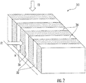
- FIGS. 1 and 2 an example of a heat exchanger 20 configured to efficiently transfer heat from a first fluid to a second fluid is illustrated.
- the illustrated heat exchanger 20 is generally rectangular in shape; however, other shapes are also contemplated herein.
- a first fluid inlet header 22, an first fluid outlet header 24, a second fluid inlet header 26 and a second fluid outlet header 28 are arranged in fluid communication with a core 30 of the heat exchanger 20 such that heat is configured to transfer between the first fluid and the second fluid within the heat exchanger 20.
- first fluid inlet header 22 and the first fluid outlet header 24 are disposed adjacent opposite surfaces of the core 30.
- first fluid inlet header 22 and the first fluid outlet header 24 may be located adjacent the same surface of the core 30.
- second fluid inlet header 26 and the second fluid outlet header 28 are shown as being arranged adjacent opposing surfaces of the core 30, for example, a top and bottom of the core 30, respectively.
- the second fluid inlet and outlet headers 26, 28 may also be arranged on the same side of the core 30. It should be understood that a heat exchanger having any configuration where one or more fluids enter the core via at least one surface and exit the core via at least one surface is contemplated herein.
- the core 30 of the first heat exchanger 20 has a plate-fin construction with crossflow of a first warm fluid (first fluid) and a second cool fluid there through.
- first fluid first warm fluid
- second cool fluid second cool fluid
- a heat exchanger 20 having another type of construction may be used, including, but are not limited to, double pipe, shell and tube, plate, plate and shell, adiabatic shell, plate fine, pillow plate, and fluid heat exchangers.
- the core 30 of the heat exchanger 20 includes a plurality of first fluid layers or segments 32 and second fluid layers segments 34.
- the first fluid layers 32 define a fluid pathway such that the first fluid is configured to flow through the core 30 in a first direction, indicated by arrow F1.
- the second fluid layers 34 define a fluid pathway such that the second fluid flows through the core 30 in a second direction, indicated by arrow F2.
- the direction of the second fluid flow is substantially perpendicular to the direction of the first fluid flow.
- the flows have other configurations, such as counter flow, or cross-counter flow for example are also contemplated herein.
- the first and second fluid layers 32, 34 are alternately stacked along the height H of the core 30.
- thin plates 36 separate adjacent fluid layers 32, 34.
- each of the plurality of first fluid layers 32 includes an array of fins 40.
- the fins 40 may be brazed, soldered, welded, or otherwise coupled to a surface of at least one of the adjacent second fluid layers 34.
- the fins 40 act as a heat sink to increase the surface area of the second fluid layers 34 arranged in contact with the cool first fluid flow.
- Different portions of the heat exchanger 20 are susceptible to different failure modes at different temperatures of operation.
- the headers or manifolds 22, 24, 26, 28 of the heat exchanger 20 are more likely to fail as a result of creep (deformation due to the prolonged exposure of mechanical and thermal stresses acting thereon), whereas the layers 32, 34 within the core 30 of the heat exchanger 20 are more likely to fail due to fatigue, weakening of the material which occurs due to the cyclical application of loads. Accordingly, it is desirable to manufacture a heat exchanger 20 where each section or component thereof has a reduced likelihood of failure without overdesigning the heat exchanger.
- Properties that are critical to performance of the heat exchanger 20 include material strength, surface roughness, and fin thickness. Accordingly, these properties may vary across the heat exchanger 20 to reduce the likelihood of failure of the heat exchanger 20. These properties may be selected to withstand the one or more failure modes associated with each section, location, or component of the heat exchanger 20. In an embodiment, this variation in one or more properties is achieved by forming the heat exchanger 20 through an additive manufacturing process, such as a laser power bed fusion process for example. However, it should be understood that other suitable additive manufacturing processes are also contemplated herein.
- a generally powdered material such as a powered metal, metal alloy, ceramic, polymer or composite material for example, to form a shape.
- the energy source include but are not limited to, an electron beam, a laser, or any other suitable energy source known to a person having ordinary skill in the art for example.
- the energy or heat from the energy source is configured to locally melt the powdered material such that the powdered material fuses into a substantially solid part to create a generally two-dimensional section of the component being formed.
- the plurality of components of the heat exchanger 20, i.e. the headers 22, 24, 26, 28 and the layers 32, 34 and fins 40 that define the core 30, may be integrally formed as a single unit. Alternatively, the components may be formed separately, such as through one or more additive manufacturing processes, and then connected to define the heat exchanger 20.
- controllable parameters may relate to the energy source and how energy is applied to the powdered material, such as such as laser orientation, laser speed, and laser power for example. Adjustment of such parameters may be used to optimize the material microstructure, and more specifically the grain size and grain orientation, at localized areas of the heat exchanger 20. For example, reducing the speed of the laser and increasing the power of the laser slows the solidification rate and increases the grain size of the portion of the heat exchanger being formed.
- the processing parameters are controlled during the manufacture of the heat exchanger 20 so that portions of the heat exchanger 20 that are susceptible to creep (i.e. the manifolds 22, 24, 26, and 28) are formed having larger grains and portions of the heat exchanger that are susceptible to fatigue have smaller grains.
- Manipulation of the microstructure not only changes the material properties of each section of the heat exchanger, but also improves the strength of the material, as needed.
- the material strength can be enhanced by controlling the directionality and refinement of the grain structure.
- the material strength is improved by increasing the laser speed and reducing the laser power to produce elongated grains that extend in the direction of the build orientation.
- the material fatigue properties can be improved by manipulating the laser parameters to make the grains as close to equiaxed as possible.
- the pattern of movement of the laser during the additive manufacturing process can be used to control the geometry and surface finish of one or more portions of the heat exchanger. By controlling the surface roughness of the heat exchanger, the fluid pressure drop across the heat exchanger may be reduced and/or minimized.
- the laser is movable in a linear scanning pattern at the interface between the fins 40 and the adjacent layers 32, 34.
- the linear scanning pattern is intended to melt the fin area to achieve thinner walls and an enhanced surface finish.
- the operational parameters of the laser applied to the interface between the manifolds 22, 24, 26, 28 and the core 30 may be selected to produce equiaxed grain structure that is favorable for both fatigue and creep.
- the thickness and uniformity of a feature are also dependent on the processing parameters and the orientation of the feature with respect to the build orientation.
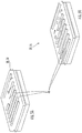
- the graph of FIG. 4 illustrates the relationship between the thickness of a fin and the energy density (laser power/laser speed) used to fabricate the fin based on the geometry of the fin. As shown, the graph compares two similar fin configurations including vertically extending fins, shown in more detail in FIG. 5A and fins that are oriented at a 45° angle, shown in more detail in FIG. 5B . Accordingly, depending on fin orientation with respect to the build orientation, different fins located at different areas of the heat exchanger will have different wall thicknesses. Therefore, the use of geometry specific process parameters enables control of wall thickness and uniformity throughout the heat exchanger.
- a stereolithography file that describes the geometry of the heat exchanger 20 is generated, for example based on a three dimensional model of the heat exchanger 20 created using a computer aided design (CAD) software.
- the file comprises a compilation of a plurality of files.
- Each of the plurality of files is associated with a portion of component of the heat exchanger and includes a geometry, laser parameters and scanning strategies associated with the manufacture thereof.
- the stereolithography file is provided as an input to a preprocessing software configured to slice the surface geometry of the heat exchanger 20 into a plurality of thin layers, as illustrated in block 104. The thickness of each of the plurality of thin layers will vary depending on the specific additive metal fabrication process used, as well as the size of the heat exchanger 20.
- each thin layer is integrally formed with at least one adjacent thin layer to form a unitary heat exchanger 20.
- the heat exchanger 20 may be heat treated to eliminate residual stresses in the heat exchanger 20, as illustrated in block 112.
- a protective coating may be applied to the heat exchanger 20, in block 112, based on the intended application of the heat exchanger 20.
- heat exchanger 20 By forming a heat exchanger 20 using an additive metal fabrication process, different portions of the heat exchanger 20 may be formed with an optimized material strength, surface roughness, and fin thickness suitable to overcome expected failure modes.
- fabrication using an additive process offers significant advantages over conventional methods in both production time and cost.
Landscapes
- Engineering & Computer Science (AREA)
- Chemical & Material Sciences (AREA)
- Mechanical Engineering (AREA)
- Materials Engineering (AREA)
- Physics & Mathematics (AREA)
- Manufacturing & Machinery (AREA)
- Optics & Photonics (AREA)
- General Engineering & Computer Science (AREA)
- Thermal Sciences (AREA)
- Health & Medical Sciences (AREA)
- Toxicology (AREA)
- Automation & Control Theory (AREA)
- Ceramic Engineering (AREA)
- Plasma & Fusion (AREA)
- Microelectronics & Electronic Packaging (AREA)
- Powder Metallurgy (AREA)
- Laser Beam Processing (AREA)
Applications Claiming Priority (1)
| Application Number | Priority Date | Filing Date | Title |
|---|---|---|---|
| US15/478,399 US10094628B1 (en) | 2017-04-04 | 2017-04-04 | Heat exchanger |
Publications (3)
| Publication Number | Publication Date |
|---|---|
| EP3392588A2 true EP3392588A2 (de) | 2018-10-24 |
| EP3392588A3 EP3392588A3 (de) | 2019-01-23 |
| EP3392588B1 EP3392588B1 (de) | 2021-08-18 |
Family
ID=61906652
Family Applications (1)
| Application Number | Title | Priority Date | Filing Date |
|---|---|---|---|
| EP18165657.0A Active EP3392588B1 (de) | 2017-04-04 | 2018-04-04 | Wärmetauscher |
Country Status (2)
| Country | Link |
|---|---|
| US (2) | US10094628B1 (de) |
| EP (1) | EP3392588B1 (de) |
Families Citing this family (6)
| Publication number | Priority date | Publication date | Assignee | Title |
|---|---|---|---|---|
| US11306979B2 (en) | 2018-12-05 | 2022-04-19 | Hamilton Sundstrand Corporation | Heat exchanger riblet and turbulator features for improved manufacturability and performance |
| EP3809087B1 (de) | 2019-10-18 | 2022-04-27 | Hamilton Sundstrand Corporation | Wärmetauscher |
| CN115176121A (zh) * | 2020-02-27 | 2022-10-11 | 三菱重工业株式会社 | 热交换芯、热交换器以及热交换芯的制造方法 |
| JP7437971B2 (ja) | 2020-02-27 | 2024-02-26 | 三菱重工業株式会社 | 熱交換コアの製造方法 |
| CN113028867A (zh) * | 2021-03-24 | 2021-06-25 | 哈尔滨锅炉厂有限责任公司 | 一种多股流体换热用微通道换热器 |
| US11493286B1 (en) * | 2021-10-12 | 2022-11-08 | Hamilton Sundstrand Corporation | Header for high-pressure heat exchanger |
Family Cites Families (9)
| Publication number | Priority date | Publication date | Assignee | Title |
|---|---|---|---|---|
| US6730998B1 (en) * | 2000-02-10 | 2004-05-04 | Micron Technology, Inc. | Stereolithographic method for fabricating heat sinks, stereolithographically fabricated heat sinks, and semiconductor devices including same |
| JP2003053523A (ja) * | 2001-08-14 | 2003-02-26 | Mitsubishi Alum Co Ltd | 熱交換器およびその製造方法 |
| US10336007B2 (en) * | 2014-05-09 | 2019-07-02 | United Technologies Corporation | Sensor fusion for powder bed manufacturing process control |
| US20160114425A1 (en) * | 2014-07-03 | 2016-04-28 | Jian Liu | Method for Manipulating Microstructure and Grain Size in Laser Three-Dimensional Additive Manufacturing |
| US9914282B2 (en) * | 2014-09-05 | 2018-03-13 | United Technologies Corporation | Composite material with controlled fracture regions |
| JP6174655B2 (ja) * | 2014-10-21 | 2017-08-02 | ユナイテッド テクノロジーズ コーポレイションUnited Technologies Corporation | ガスタービンエンジン用のダクテッド熱交換器システム、およびガスタービンエンジン用の熱交換器の製造方法 |
| US9835380B2 (en) * | 2015-03-13 | 2017-12-05 | General Electric Company | Tube in cross-flow conduit heat exchanger |
| US20160281532A1 (en) * | 2015-03-24 | 2016-09-29 | General Electric Company | Heat exchanger for a gas turbine engine |
| US10099325B2 (en) * | 2015-04-15 | 2018-10-16 | Delavan Inc. | Method for manufacturing a hybrid heat exchanger |
-
2017
- 2017-04-04 US US15/478,399 patent/US10094628B1/en active Active
-
2018
- 2018-04-04 EP EP18165657.0A patent/EP3392588B1/de active Active
- 2018-07-16 US US16/036,657 patent/US10941992B2/en active Active
Non-Patent Citations (1)
| Title |
|---|
| None |
Also Published As
| Publication number | Publication date |
|---|---|
| EP3392588B1 (de) | 2021-08-18 |
| US20180328676A1 (en) | 2018-11-15 |
| US10094628B1 (en) | 2018-10-09 |
| EP3392588A3 (de) | 2019-01-23 |
| US10941992B2 (en) | 2021-03-09 |
| US20180283810A1 (en) | 2018-10-04 |
Similar Documents
| Publication | Publication Date | Title |
|---|---|---|
| US10941992B2 (en) | Heat exchanger | |
| JP7040707B2 (ja) | 付加製造された熱交換器 | |
| US7866377B2 (en) | Method of using minimal surfaces and minimal skeletons to make heat exchanger components | |
| EP3258203B1 (de) | Komplexer flachrohrwärmetauscher | |
| EP2781872B1 (de) | Wärmetauscherentwurf und herstellung | |
| US20170023311A1 (en) | Enhanced Heat Transfer In Plate-Fin Heat Exchangers | |
| US7810552B2 (en) | Method of making a heat exchanger | |
| US10422586B2 (en) | Heat exchanger | |
| US9134072B2 (en) | Geometry of heat exchanger with high efficiency | |
| EP3018349A2 (de) | Rotierender schraubenkompressor | |
| EP3663694B1 (de) | Wärmetauscherrippenmerkmale für verbesserte herstellbarkeit und leistung | |
| US20210254896A1 (en) | Heat exchanger with undulating plates | |
| US20200370836A1 (en) | Heat exchanger comprising a multi-channel distribution element | |
| EP3809087B1 (de) | Wärmetauscher | |
| EP3246645B1 (de) | Wärmetauscher mit geschachtelter schleife | |
| AU2020204326B2 (en) | Thermal management system and method | |
| CN116057487A (zh) | 一种用于生产技术设备的部分增材制造型部件的方法 | |
| EP4108458A1 (de) | Wellenförmiger wärmetauscherkern mit angrenzendem durchgang | |
| EP4109027A1 (de) | Wellenförmiger wärmetauscherkern mit angrenzendem durchgang und verteiler | |
| EP3647703B1 (de) | Generativ gefertigte rippenschlitze für wärmeausdehnung | |
| KR20210001185A (ko) | 열교환기 |
Legal Events
| Date | Code | Title | Description |
|---|---|---|---|
| PUAI | Public reference made under article 153(3) epc to a published international application that has entered the european phase |
Free format text: ORIGINAL CODE: 0009012 |
|
| STAA | Information on the status of an ep patent application or granted ep patent |
Free format text: STATUS: THE APPLICATION HAS BEEN PUBLISHED |
|
| AK | Designated contracting states |
Kind code of ref document: A2 Designated state(s): AL AT BE BG CH CY CZ DE DK EE ES FI FR GB GR HR HU IE IS IT LI LT LU LV MC MK MT NL NO PL PT RO RS SE SI SK SM TR |
|
| AX | Request for extension of the european patent |
Extension state: BA ME |
|
| PUAL | Search report despatched |
Free format text: ORIGINAL CODE: 0009013 |
|
| AK | Designated contracting states |
Kind code of ref document: A3 Designated state(s): AL AT BE BG CH CY CZ DE DK EE ES FI FR GB GR HR HU IE IS IT LI LT LU LV MC MK MT NL NO PL PT RO RS SE SI SK SM TR |
|
| AX | Request for extension of the european patent |
Extension state: BA ME |
|
| RIC1 | Information provided on ipc code assigned before grant |
Ipc: G03F 7/00 20060101ALI20181218BHEP Ipc: B22F 3/00 20060101ALI20181218BHEP Ipc: B29C 64/135 20170101ALI20181218BHEP Ipc: F28D 1/00 20060101AFI20181218BHEP Ipc: B28B 1/00 20060101ALI20181218BHEP |
|
| STAA | Information on the status of an ep patent application or granted ep patent |
Free format text: STATUS: REQUEST FOR EXAMINATION WAS MADE |
|
| 17P | Request for examination filed |
Effective date: 20190722 |
|
| RBV | Designated contracting states (corrected) |
Designated state(s): AL AT BE BG CH CY CZ DE DK EE ES FI FR GB GR HR HU IE IS IT LI LT LU LV MC MK MT NL NO PL PT RO RS SE SI SK SM TR |
|
| STAA | Information on the status of an ep patent application or granted ep patent |
Free format text: STATUS: EXAMINATION IS IN PROGRESS |
|
| 17Q | First examination report despatched |
Effective date: 20200520 |
|
| STAA | Information on the status of an ep patent application or granted ep patent |
Free format text: STATUS: EXAMINATION IS IN PROGRESS |
|
| GRAP | Despatch of communication of intention to grant a patent |
Free format text: ORIGINAL CODE: EPIDOSNIGR1 |
|
| STAA | Information on the status of an ep patent application or granted ep patent |
Free format text: STATUS: GRANT OF PATENT IS INTENDED |
|
| RIC1 | Information provided on ipc code assigned before grant |
Ipc: B28B 1/00 20060101ALI20210217BHEP Ipc: B29C 64/135 20170101ALI20210217BHEP Ipc: B22F 10/20 20210101ALI20210217BHEP Ipc: G03F 7/00 20060101ALI20210217BHEP Ipc: B29C 64/153 20170101ALI20210217BHEP Ipc: F28D 1/00 20060101AFI20210217BHEP Ipc: B29L 31/18 20060101ALI20210217BHEP Ipc: B22F 5/10 20060101ALI20210217BHEP Ipc: B22F 3/00 20210101ALI20210217BHEP Ipc: B29C 64/282 20170101ALI20210217BHEP Ipc: B29C 64/386 20170101ALI20210217BHEP |
|
| INTG | Intention to grant announced |
Effective date: 20210316 |
|
| GRAS | Grant fee paid |
Free format text: ORIGINAL CODE: EPIDOSNIGR3 |
|
| GRAA | (expected) grant |
Free format text: ORIGINAL CODE: 0009210 |
|
| STAA | Information on the status of an ep patent application or granted ep patent |
Free format text: STATUS: THE PATENT HAS BEEN GRANTED |
|
| AK | Designated contracting states |
Kind code of ref document: B1 Designated state(s): AL AT BE BG CH CY CZ DE DK EE ES FI FR GB GR HR HU IE IS IT LI LT LU LV MC MK MT NL NO PL PT RO RS SE SI SK SM TR |
|
| REG | Reference to a national code |
Ref country code: GB Ref legal event code: FG4D |
|
| REG | Reference to a national code |
Ref country code: CH Ref legal event code: EP |
|
| REG | Reference to a national code |
Ref country code: DE Ref legal event code: R096 Ref document number: 602018021888 Country of ref document: DE |
|
| REG | Reference to a national code |
Ref country code: IE Ref legal event code: FG4D Ref country code: AT Ref legal event code: REF Ref document number: 1421999 Country of ref document: AT Kind code of ref document: T Effective date: 20210915 |
|
| REG | Reference to a national code |
Ref country code: LT Ref legal event code: MG9D |
|
| REG | Reference to a national code |
Ref country code: NL Ref legal event code: MP Effective date: 20210818 |
|
| REG | Reference to a national code |
Ref country code: AT Ref legal event code: MK05 Ref document number: 1421999 Country of ref document: AT Kind code of ref document: T Effective date: 20210818 |
|
| PG25 | Lapsed in a contracting state [announced via postgrant information from national office to epo] |
Ref country code: HR Free format text: LAPSE BECAUSE OF FAILURE TO SUBMIT A TRANSLATION OF THE DESCRIPTION OR TO PAY THE FEE WITHIN THE PRESCRIBED TIME-LIMIT Effective date: 20210818 Ref country code: ES Free format text: LAPSE BECAUSE OF FAILURE TO SUBMIT A TRANSLATION OF THE DESCRIPTION OR TO PAY THE FEE WITHIN THE PRESCRIBED TIME-LIMIT Effective date: 20210818 Ref country code: FI Free format text: LAPSE BECAUSE OF FAILURE TO SUBMIT A TRANSLATION OF THE DESCRIPTION OR TO PAY THE FEE WITHIN THE PRESCRIBED TIME-LIMIT Effective date: 20210818 Ref country code: RS Free format text: LAPSE BECAUSE OF FAILURE TO SUBMIT A TRANSLATION OF THE DESCRIPTION OR TO PAY THE FEE WITHIN THE PRESCRIBED TIME-LIMIT Effective date: 20210818 Ref country code: SE Free format text: LAPSE BECAUSE OF FAILURE TO SUBMIT A TRANSLATION OF THE DESCRIPTION OR TO PAY THE FEE WITHIN THE PRESCRIBED TIME-LIMIT Effective date: 20210818 Ref country code: PT Free format text: LAPSE BECAUSE OF FAILURE TO SUBMIT A TRANSLATION OF THE DESCRIPTION OR TO PAY THE FEE WITHIN THE PRESCRIBED TIME-LIMIT Effective date: 20211220 Ref country code: NO Free format text: LAPSE BECAUSE OF FAILURE TO SUBMIT A TRANSLATION OF THE DESCRIPTION OR TO PAY THE FEE WITHIN THE PRESCRIBED TIME-LIMIT Effective date: 20211118 Ref country code: AT Free format text: LAPSE BECAUSE OF FAILURE TO SUBMIT A TRANSLATION OF THE DESCRIPTION OR TO PAY THE FEE WITHIN THE PRESCRIBED TIME-LIMIT Effective date: 20210818 Ref country code: BG Free format text: LAPSE BECAUSE OF FAILURE TO SUBMIT A TRANSLATION OF THE DESCRIPTION OR TO PAY THE FEE WITHIN THE PRESCRIBED TIME-LIMIT Effective date: 20211118 Ref country code: LT Free format text: LAPSE BECAUSE OF FAILURE TO SUBMIT A TRANSLATION OF THE DESCRIPTION OR TO PAY THE FEE WITHIN THE PRESCRIBED TIME-LIMIT Effective date: 20210818 |
|
| PG25 | Lapsed in a contracting state [announced via postgrant information from national office to epo] |
Ref country code: PL Free format text: LAPSE BECAUSE OF FAILURE TO SUBMIT A TRANSLATION OF THE DESCRIPTION OR TO PAY THE FEE WITHIN THE PRESCRIBED TIME-LIMIT Effective date: 20210818 Ref country code: LV Free format text: LAPSE BECAUSE OF FAILURE TO SUBMIT A TRANSLATION OF THE DESCRIPTION OR TO PAY THE FEE WITHIN THE PRESCRIBED TIME-LIMIT Effective date: 20210818 Ref country code: GR Free format text: LAPSE BECAUSE OF FAILURE TO SUBMIT A TRANSLATION OF THE DESCRIPTION OR TO PAY THE FEE WITHIN THE PRESCRIBED TIME-LIMIT Effective date: 20211119 |
|
| PG25 | Lapsed in a contracting state [announced via postgrant information from national office to epo] |
Ref country code: NL Free format text: LAPSE BECAUSE OF FAILURE TO SUBMIT A TRANSLATION OF THE DESCRIPTION OR TO PAY THE FEE WITHIN THE PRESCRIBED TIME-LIMIT Effective date: 20210818 |
|
| PG25 | Lapsed in a contracting state [announced via postgrant information from national office to epo] |
Ref country code: DK Free format text: LAPSE BECAUSE OF FAILURE TO SUBMIT A TRANSLATION OF THE DESCRIPTION OR TO PAY THE FEE WITHIN THE PRESCRIBED TIME-LIMIT Effective date: 20210818 |
|
| REG | Reference to a national code |
Ref country code: DE Ref legal event code: R097 Ref document number: 602018021888 Country of ref document: DE |
|
| PG25 | Lapsed in a contracting state [announced via postgrant information from national office to epo] |
Ref country code: SM Free format text: LAPSE BECAUSE OF FAILURE TO SUBMIT A TRANSLATION OF THE DESCRIPTION OR TO PAY THE FEE WITHIN THE PRESCRIBED TIME-LIMIT Effective date: 20210818 Ref country code: SK Free format text: LAPSE BECAUSE OF FAILURE TO SUBMIT A TRANSLATION OF THE DESCRIPTION OR TO PAY THE FEE WITHIN THE PRESCRIBED TIME-LIMIT Effective date: 20210818 Ref country code: RO Free format text: LAPSE BECAUSE OF FAILURE TO SUBMIT A TRANSLATION OF THE DESCRIPTION OR TO PAY THE FEE WITHIN THE PRESCRIBED TIME-LIMIT Effective date: 20210818 Ref country code: EE Free format text: LAPSE BECAUSE OF FAILURE TO SUBMIT A TRANSLATION OF THE DESCRIPTION OR TO PAY THE FEE WITHIN THE PRESCRIBED TIME-LIMIT Effective date: 20210818 Ref country code: CZ Free format text: LAPSE BECAUSE OF FAILURE TO SUBMIT A TRANSLATION OF THE DESCRIPTION OR TO PAY THE FEE WITHIN THE PRESCRIBED TIME-LIMIT Effective date: 20210818 Ref country code: AL Free format text: LAPSE BECAUSE OF FAILURE TO SUBMIT A TRANSLATION OF THE DESCRIPTION OR TO PAY THE FEE WITHIN THE PRESCRIBED TIME-LIMIT Effective date: 20210818 |
|
| PLBE | No opposition filed within time limit |
Free format text: ORIGINAL CODE: 0009261 |
|
| STAA | Information on the status of an ep patent application or granted ep patent |
Free format text: STATUS: NO OPPOSITION FILED WITHIN TIME LIMIT |
|
| 26N | No opposition filed |
Effective date: 20220519 |
|
| PG25 | Lapsed in a contracting state [announced via postgrant information from national office to epo] |
Ref country code: IT Free format text: LAPSE BECAUSE OF FAILURE TO SUBMIT A TRANSLATION OF THE DESCRIPTION OR TO PAY THE FEE WITHIN THE PRESCRIBED TIME-LIMIT Effective date: 20210818 |
|
| PG25 | Lapsed in a contracting state [announced via postgrant information from national office to epo] |
Ref country code: SI Free format text: LAPSE BECAUSE OF FAILURE TO SUBMIT A TRANSLATION OF THE DESCRIPTION OR TO PAY THE FEE WITHIN THE PRESCRIBED TIME-LIMIT Effective date: 20210818 |
|
| REG | Reference to a national code |
Ref country code: CH Ref legal event code: PL |
|
| REG | Reference to a national code |
Ref country code: BE Ref legal event code: MM Effective date: 20220430 |
|
| PG25 | Lapsed in a contracting state [announced via postgrant information from national office to epo] |
Ref country code: MC Free format text: LAPSE BECAUSE OF FAILURE TO SUBMIT A TRANSLATION OF THE DESCRIPTION OR TO PAY THE FEE WITHIN THE PRESCRIBED TIME-LIMIT Effective date: 20210818 Ref country code: LU Free format text: LAPSE BECAUSE OF NON-PAYMENT OF DUE FEES Effective date: 20220404 Ref country code: LI Free format text: LAPSE BECAUSE OF NON-PAYMENT OF DUE FEES Effective date: 20220430 Ref country code: CH Free format text: LAPSE BECAUSE OF NON-PAYMENT OF DUE FEES Effective date: 20220430 |
|
| PG25 | Lapsed in a contracting state [announced via postgrant information from national office to epo] |
Ref country code: BE Free format text: LAPSE BECAUSE OF NON-PAYMENT OF DUE FEES Effective date: 20220430 |
|
| PG25 | Lapsed in a contracting state [announced via postgrant information from national office to epo] |
Ref country code: IE Free format text: LAPSE BECAUSE OF NON-PAYMENT OF DUE FEES Effective date: 20220404 |
|
| PGFP | Annual fee paid to national office [announced via postgrant information from national office to epo] |
Ref country code: FR Payment date: 20230321 Year of fee payment: 6 |
|
| P01 | Opt-out of the competence of the unified patent court (upc) registered |
Effective date: 20230522 |
|
| PGFP | Annual fee paid to national office [announced via postgrant information from national office to epo] |
Ref country code: DE Payment date: 20230321 Year of fee payment: 6 |
|
| PG25 | Lapsed in a contracting state [announced via postgrant information from national office to epo] |
Ref country code: HU Free format text: LAPSE BECAUSE OF FAILURE TO SUBMIT A TRANSLATION OF THE DESCRIPTION OR TO PAY THE FEE WITHIN THE PRESCRIBED TIME-LIMIT; INVALID AB INITIO Effective date: 20180404 |
|
| PG25 | Lapsed in a contracting state [announced via postgrant information from national office to epo] |
Ref country code: MK Free format text: LAPSE BECAUSE OF FAILURE TO SUBMIT A TRANSLATION OF THE DESCRIPTION OR TO PAY THE FEE WITHIN THE PRESCRIBED TIME-LIMIT Effective date: 20210818 Ref country code: CY Free format text: LAPSE BECAUSE OF FAILURE TO SUBMIT A TRANSLATION OF THE DESCRIPTION OR TO PAY THE FEE WITHIN THE PRESCRIBED TIME-LIMIT Effective date: 20210818 |
|
| PGFP | Annual fee paid to national office [announced via postgrant information from national office to epo] |
Ref country code: GB Payment date: 20240320 Year of fee payment: 7 |