EP3392454A1 - Downhole measuring module and a downhole inflow system - Google Patents
Downhole measuring module and a downhole inflow system Download PDFInfo
- Publication number
- EP3392454A1 EP3392454A1 EP17167532.5A EP17167532A EP3392454A1 EP 3392454 A1 EP3392454 A1 EP 3392454A1 EP 17167532 A EP17167532 A EP 17167532A EP 3392454 A1 EP3392454 A1 EP 3392454A1
- Authority
- EP
- European Patent Office
- Prior art keywords
- downhole
- metal structure
- tubular metal
- fluid
- well tubular
- Prior art date
- Legal status (The legal status is an assumption and is not a legal conclusion. Google has not performed a legal analysis and makes no representation as to the accuracy of the status listed.)
- Withdrawn
Links
Images



Classifications
-
- E—FIXED CONSTRUCTIONS
- E21—EARTH OR ROCK DRILLING; MINING
- E21B—EARTH OR ROCK DRILLING; OBTAINING OIL, GAS, WATER, SOLUBLE OR MELTABLE MATERIALS OR A SLURRY OF MINERALS FROM WELLS
- E21B43/00—Methods or apparatus for obtaining oil, gas, water, soluble or meltable materials or a slurry of minerals from wells
- E21B43/12—Methods or apparatus for controlling the flow of the obtained fluid to or in wells
-
- E—FIXED CONSTRUCTIONS
- E21—EARTH OR ROCK DRILLING; MINING
- E21B—EARTH OR ROCK DRILLING; OBTAINING OIL, GAS, WATER, SOLUBLE OR MELTABLE MATERIALS OR A SLURRY OF MINERALS FROM WELLS
- E21B47/00—Survey of boreholes or wells
- E21B47/10—Locating fluid leaks, intrusions or movements
-
- E—FIXED CONSTRUCTIONS
- E21—EARTH OR ROCK DRILLING; MINING
- E21B—EARTH OR ROCK DRILLING; OBTAINING OIL, GAS, WATER, SOLUBLE OR MELTABLE MATERIALS OR A SLURRY OF MINERALS FROM WELLS
- E21B43/00—Methods or apparatus for obtaining oil, gas, water, soluble or meltable materials or a slurry of minerals from wells
- E21B43/14—Obtaining from a multiple-zone well
Definitions
- the present invention relates to a downhole measuring module configured to be mounted on an outer face or as part of a well tubular metal structure having an inflow section for allowing flow of fluid from a reservoir into the well tubular metal structure. Furthermore, the present invention relates to a downhole inflow system, to a downhole system comprising a well tubular metal structure and one or more downhole inflow systems according to the present invention and to a method for measuring a condition of a fluid downhole.
- the operators When producing hydrocarbon-containing fluid from a reservoir through several zones in a well tubular metal structure in a borehole of a well, the operators would like to gain information of the fluid flowing through each zone in order to open, choke or close zones not producing in an optimised manner in relation to the resulting fluid flowing to surface.
- the oil may be too thick for the well to be self-producing, and by letting more water in through another zone, the density may be adjusted so that the well becomes self-producing again.
- a downhole measuring module configured to be mounted on an outer face or as part of a well tubular metal structure having an inflow section for allowing flow of fluid from a reservoir into the well tubular metal structure, said downhole measuring module comprising:
- fluid from openings in a shroud or screen is guided through the flow channels of the downhole measuring module, and the sensors measure at least one condition of the fluid in the flow channels upstream of the inflow section.
- the sensors measure at least one condition of the fluid in the flow channels upstream of the inflow section.
- the downhole measuring module according to the present invention may also comprise a power source configured to provide power to the sensors.
- tubular part may be mounted from at least two parts circumferenting the well tubular metal structure.
- the flow channels may be provided in a wall of the tubular part.
- flow channels may be grooves in the tubular parts.
- the sensors may be configured to measure one or more of the conditions: pressure, conductivity, content, velocity and/or temperature.
- Such sensors may be pressure sensors, temperature sensors, capacitance sensors, optical probes, Doppler flow meters and/or acoustic sensors.
- sensors may be arranged in one flow channel.
- the present invention also relates to a downhole inflow system comprising:
- the downhole inflow system guides fluid from the openings in the shroud through the flow channels of the downhole measuring module, and measures at least one condition of the fluid in the flow channels by means of the sensors arranged in at least some of the flow channels upstream of the inflow section.
- all fluid is measured upstream of the inflow section, and by directing all fluid in through the flow channels, a more accurate measurement is obtained rather than only performing measurements in one channel, which is e.g. arranged at the top, as the fluid in that channel may comprise more gas than the more heavy oil and thus result in a more inaccurate measurement of the total flow content.
- shroud may be connected with the well tubular metal structure by means of connection parts.
- the downhole inflow system may further comprise a first communication module configured to communicate data measured by the sensors.
- the downhole inflow system may further comprise a control line electrically connected with the first communication module for communicating with and providing power supply to the sensors.
- the first communication module may comprise an inductive unit arranged exterior of the well tubular metal structure for conducting power and/or data through the well tubular metal structure.
- the inductive unit may comprise a coil helically wound around the well tubular metal structure.
- the first communication module may be configured to transmit and/or receive power and/or data to a wireline tool inside the well tubular metal structure.
- the downhole inflow system according to the present invention may further comprise several second communication modules functioning as repeaters to and from a unit arranged near a top of the well tubular metal structure or at surface.
- the downhole inflow system may comprise a wireline tool arranged in the well tubular metal structure in the vicinity of the first communication module.
- first communication module and/or the second communication modules may comprise an acoustic transceiver.
- the flow channels of the downhole measuring module may be distributed along a periphery of the well tubular metal structure.
- Each flow channel may comprise at least one of the sensors.
- the first communication module may be arranged at a distance from the downhole measuring module so that the fluid flows freely from the openings to the downhole measuring module.
- tubular part of the downhole measuring module may have an outer module face abutting the shroud.
- outer module face may be abutting along the entire circumference of the shroud.
- a power source may be arranged configured to provide power to the sensors.
- the shroud may have a first shroud part and a second shroud part, the downhole measuring module being connected to the first shroud part and the second shroud part, so that all fluid underneath the first shroud part is fluidly connected with the fluid underneath the second shroud part through the flow channels of the downhole measuring module.
- the present invention also relates to a downhole system comprising a well tubular metal structure and one or more downhole inflow systems according to the present invention.
- the present invention relates to a method for measuring a condition of a fluid downhole, comprising:
- All fluid may be measured upstream of the inflow section.
- Fig. 1 shows a downhole measuring module 1 configured to be mounted on an outer face 2 or as part of a well tubular metal structure 3, as shown in Fig. 2 .
- the well tubular metal structure 3 of Fig. 2 has an inflow section 50 for allowing flow of fluid from a reservoir 60 into a borehole 61 in which the well tubular metal structure is arranged.
- the downhole measuring module 1 of Fig. 1 comprises a tubular part 4 comprising a plurality of flow channels 5 arranged exterior of the outer face.
- the downhole measuring module 1 further comprises a plurality of sensors 6 provided in at least some of the flow channels for measuring a condition of the fluid upstream of the inflow section.
- the tubular part 4 is mounted from two parts 4A, 4B, which parts connected circumferent the well tubular metal structure.
- the tubular part 4 may also be a one-piece tubular which is crimped onto the outer face 2 of the well tubular metal structure 3.
- the flow channels 5 are provided in a wall 7 of the tubular part 4 and extend along the outer face 2 of the well tubular metal structure 3 and fluidly connect the inflow section and the section on the other side upstream of the downhole measuring module 1.
- the flow channels are grooves 17 in the tubular part 4 facing the outer face 2 of the well tubular metal structure 3, and thus the tubular part 4 forms flow channels 5 together with the well tubular metal structure 3.
- the sensors are configured to measure one or more of the following conditions: pressure, conductivity, content, velocity and/or temperature.
- the sensors may be pressure sensors, temperature sensors, capacitance sensors, optical probes, Doppler flow meters and/or acoustic sensors. There may be several sensors arranged in one flow channel or one sensor may extend into two flow channels.
- the downhole measuring module 1 comprises a power source 8 configured to provide power to the sensors 6.
- the power source 8 is a control line 9 which is an electrical conductor 9.
- the downhole measuring module 1 forms part of a downhole inflow system 100, as shown in Fig. 3 , comprising a shroud 10 mounted exterior of and circumferenting the well tubular metal structure 3 opposite the inflow section 50 forming an annular space 51 (shown in Fig. 8 ) between the shroud 10 and the well tubular metal structure 3.
- the shroud 10 has openings 11 for allowing fluid from the reservoir into the annular space.
- the shroud is connected with the well tubular metal structure, e.g. by means of connection parts 52 as shown in Fig. 8 .
- the downhole measuring module 1 is arranged in the annular space 51 between the inflow section 50 and the openings 11 in the shroud 10, so that all fluid entering through the openings 11 is guided through the flow channels 5 in the downhole measuring module 1 before entering into the well tubular metal structure 3 through the inflow section 50.
- the downhole measuring module 1 may further comprise a processing unit 53 for processing the measurements from the sensors 6 before these measurements are communicated to surface, so that sufficient information is sent without all measured data being sent.
- the downhole inflow system 100 further comprises a first communication module configured to communicate data measured by the sensors.
- the first communication module 41 may be comprised in the downhole measuring module 1, as shown in Fig. 7 .
- the downhole inflow system 100 comprises the first communication module 41 arranged at a distance from the downhole measuring module 1, so that the fluid flows freely from the openings in the shroud to the downhole measuring module.
- the control line 9 electrically connects the downhole measuring module 1 with the first communication module 41 for communicating with and providing power supply to the sensors in the downhole measuring module 1.
- the first communication module 41 is arranged between two connections 42 connecting the communication module 41 with the outer face 2 of the well tubular metal structure 3.
- the connections 42 comprise grooves for allowing fluid to flow past the connections 42 and the first communication module 41.
- the first communication module 41 comprises an inductive unit 44 arranged exterior of the well tubular metal structure 3 for conduction of power and/or data through the wall of the well tubular metal structure 3.
- the inductive unit 44 comprises a coil wire 45 helically wound around the well tubular metal structure to form a coil 46.
- the first communication module 41 of Fig. 4 is configured to transmit and/or receive power and/or data to/from a wireline tool inside the well tubular metal structure or to/from several second communication modules distributed along the well tubular metal structure to the top of the well and functioning as repeaters to and from a unit arranged near a top of the well tubular metal structure or at surface.
- the wireline tool is arranged in the well tubular metal structure in the vicinity of the first communication module 41.
- the wireline tool may have a projectable arm for abutting the inner face of the well tubular metal structure.
- the first communication module 41 and/or the second communication modules comprise/comprises an acoustic transceiver 47 for transmitting and receiving data and/or power.
- the flow channels 5 of the downhole measuring module 1 are distributed along a periphery of the well tubular metal structure 3 and the control line 9 extends into one of the flow channels.
- a sensor may be arranged in each of the other flow channels.
- each flow channel comprises at least one of the sensors, and some or all flow channels may comprise several sensors.
- the tubular part 4 of the downhole measuring module 1 has an outer module face 15 abutting the shroud 10.
- the outer module face 15 is abutting along the entire circumference of the shroud, so that the downhole measuring module 1 forms a restriction in the annular space 51 directing all fluid in through the flow channels.
- the shroud has a first shroud part and a second shroud part so that the downhole measuring module in one end is connected to the first shroud part and in another opposing end is connected to the second shroud part, so that all fluid underneath the first shroud part is fluidly connected with the fluid underneath the second shroud part through the flow channels of the downhole measuring module.
- the invention further relates to a downhole system 200 comprising the well tubular metal structure and one or more downhole inflow systems 100, as shown in Fig. 4 .
- the downhole system 200 further comprises annular barriers 70 for isolating a production zone 101.
- the annular barrier has a tubular unit 71 mounted as part of the well tubular metal structure and an expandable sleeve 73 surrounding the tubular unit 71 and being connected therewith by means of connection parts 72, forming an expandable space there between.
- the tubular unit has an expansion opening for allowing pressurised fluid from the well tubular metal structure into the space in order to expand the expandable sleeve 73 and form a barrier towards the inner wall of the borehole or another well tubular metal structure.
- the downhole inflow system guides fluid from the openings in the shroud through the flow channels of the downhole measuring module, and measures at least one condition of the fluid in the flow channels by means of the sensors arranged in at least some of the flow channels upstream of the inflow section.
- all fluid is measured upstream of the inflow section, and by directing all fluid in through the flow channels, a more accurate measurement is obtained rather than only performing measurements in one channel, which is e.g. arranged at the top, as the fluid in that channel may comprise more gas than the more heavy oil and thus result in a more inaccurate measurement of the total flow content.
- fluid or well fluid any kind of fluid that may be present in oil or gas wells downhole, such as natural gas, oil, oil mud, crude oil, water etc.
- gas is meant any kind of gas composition present in a well, completion, or open hole
- oil is meant any kind of oil composition, such as crude oil, an oil-containing fluid etc.
- Gas, oil, and water fluids may thus all comprise other elements or substances than gas, oil, and/or water, respectively.
- annular barrier an annular barrier comprising a tubular metal part mounted as part of the well tubular metal structure and an expandable metal sleeve surrounding and connected to the tubular part defining an annular barrier space.
- a well tubular metal structure is meant any kind of pipe, casing, tubing, tubular, liner, string etc. used downhole in relation to oil or natural gas production.
- a downhole tractor can be used to push the tool all the way into position in the well.
- the downhole tractor may have projectable arms having wheels, wherein the wheels contact the inner surface of the casing for propelling the tractor and the tool forward in the casing.
- a downhole tractor is any kind of driving tool capable of pushing or pulling tools in a well downhole, such as a Well Tractor®.
Landscapes
- Life Sciences & Earth Sciences (AREA)
- Engineering & Computer Science (AREA)
- Geology (AREA)
- Mining & Mineral Resources (AREA)
- Physics & Mathematics (AREA)
- Environmental & Geological Engineering (AREA)
- Fluid Mechanics (AREA)
- General Life Sciences & Earth Sciences (AREA)
- Geochemistry & Mineralogy (AREA)
- Geophysics (AREA)
- Measuring Volume Flow (AREA)
Abstract
The present invention relates to a downhole measuring module (1) configured to be mounted on an outer face (2) or as part of a well tubular metal structure (3) having an inflow section (50) for allowing flow of fluid from a reservoir (60) into the well tubular metal structure, said downhole measuring module comprising a tubular part comprising a plurality of flow channels (5) arranged exterior of the outer face, and a plurality of sensors (6) provided in at least some of the flow channels for measuring a condition of the fluid upstream of the inflow section, wherein the flow channels are configured to guide the fluid to flow past the sensors. Furthermore, the present invention relates to a downhole inflow system (100), to a downhole system (200) comprising a well tubular metal structure and one or more downhole inflow systems according to the present invention and to a method for measuring a condition of a fluid downhole.
Description
- The present invention relates to a downhole measuring module configured to be mounted on an outer face or as part of a well tubular metal structure having an inflow section for allowing flow of fluid from a reservoir into the well tubular metal structure. Furthermore, the present invention relates to a downhole inflow system, to a downhole system comprising a well tubular metal structure and one or more downhole inflow systems according to the present invention and to a method for measuring a condition of a fluid downhole.
- When producing hydrocarbon-containing fluid from a reservoir through several zones in a well tubular metal structure in a borehole of a well, the operators would like to gain information of the fluid flowing through each zone in order to open, choke or close zones not producing in an optimised manner in relation to the resulting fluid flowing to surface. One example is that the oil may be too thick for the well to be self-producing, and by letting more water in through another zone, the density may be adjusted so that the well becomes self-producing again.
- It is an object of the present invention to wholly or partly overcome the above disadvantages and drawbacks of the prior art. More specifically, it is an object to provide an improved downhole system enabling better adjustment of the fluid flowing in through the production zones.
- The above objects, together with numerous other objects, advantages and features, which will become evident from the below description, are accomplished by a solution in accordance with the present invention by a downhole measuring module configured to be mounted on an outer face or as part of a well tubular metal structure having an inflow section for allowing flow of fluid from a reservoir into the well tubular metal structure, said downhole measuring module comprising:
- a tubular part comprising a plurality of flow channels arranged exterior of the outer face, and
- a plurality of sensors provided in at least some of the flow channels for measuring a condition of the fluid upstream of the inflow section,
- By having a downhole measuring module having flow channels with sensors, fluid from openings in a shroud or screen is guided through the flow channels of the downhole measuring module, and the sensors measure at least one condition of the fluid in the flow channels upstream of the inflow section. Thus, all fluid is measured upstream of the inflow section, and by directing all fluid in through the flow channels, a more accurate measurement is obtained rather than only performing measurements in one channel, which is e.g. arranged at the top, as the fluid in that channel may comprise more gas than the more heavy oil and thus result in a more inaccurate measurement of the total flow content.
- The downhole measuring module according to the present invention may also comprise a power source configured to provide power to the sensors.
- Moreover, the tubular part may be mounted from at least two parts circumferenting the well tubular metal structure.
- Also, the flow channels may be provided in a wall of the tubular part.
- Further, the flow channels may be grooves in the tubular parts.
- The sensors may be configured to measure one or more of the conditions: pressure, conductivity, content, velocity and/or temperature.
- Such sensors may be pressure sensors, temperature sensors, capacitance sensors, optical probes, Doppler flow meters and/or acoustic sensors.
- Furthermore, several sensors may be arranged in one flow channel.
- The present invention also relates to a downhole inflow system comprising:
- a shroud mounted exterior of and circumferenting a well tubular metal structure opposite an inflow section forming an annular space between the shroud and the well tubular metal structure, the shroud having openings for allowing fluid from a reservoir into the annular space, the shroud being connected with the well tubular metal structure, and
- a downhole measuring module according to the present invention arranged in the annular space between the inflow section and the openings, so that all fluid entering through the openings is guided through the flow channels in the downhole measuring module before entering into the well tubular metal structure through the inflow section.
- Thus, the downhole inflow system guides fluid from the openings in the shroud through the flow channels of the downhole measuring module, and measures at least one condition of the fluid in the flow channels by means of the sensors arranged in at least some of the flow channels upstream of the inflow section. Thus, all fluid is measured upstream of the inflow section, and by directing all fluid in through the flow channels, a more accurate measurement is obtained rather than only performing measurements in one channel, which is e.g. arranged at the top, as the fluid in that channel may comprise more gas than the more heavy oil and thus result in a more inaccurate measurement of the total flow content.
- Moreover, the shroud may be connected with the well tubular metal structure by means of connection parts.
- The downhole inflow system according to the present invention may further comprise a first communication module configured to communicate data measured by the sensors.
- Also, the downhole inflow system according to the present invention may further comprise a control line electrically connected with the first communication module for communicating with and providing power supply to the sensors.
- Moreover, the first communication module may comprise an inductive unit arranged exterior of the well tubular metal structure for conducting power and/or data through the well tubular metal structure.
- Additionally, the inductive unit may comprise a coil helically wound around the well tubular metal structure.
- Furthermore, the first communication module may be configured to transmit and/or receive power and/or data to a wireline tool inside the well tubular metal structure.
- The downhole inflow system according to the present invention may further comprise several second communication modules functioning as repeaters to and from a unit arranged near a top of the well tubular metal structure or at surface.
- Further, the downhole inflow system according to the present invention may comprise a wireline tool arranged in the well tubular metal structure in the vicinity of the first communication module.
- Also, the first communication module and/or the second communication modules may comprise an acoustic transceiver.
- The flow channels of the downhole measuring module may be distributed along a periphery of the well tubular metal structure.
- Each flow channel may comprise at least one of the sensors.
- Moreover, the first communication module may be arranged at a distance from the downhole measuring module so that the fluid flows freely from the openings to the downhole measuring module.
- Furthermore, the tubular part of the downhole measuring module may have an outer module face abutting the shroud.
- In addition, the outer module face may be abutting along the entire circumference of the shroud.
- Also, a power source may be arranged configured to provide power to the sensors.
- Further, the shroud may have a first shroud part and a second shroud part, the downhole measuring module being connected to the first shroud part and the second shroud part, so that all fluid underneath the first shroud part is fluidly connected with the fluid underneath the second shroud part through the flow channels of the downhole measuring module.
- The present invention also relates to a downhole system comprising a well tubular metal structure and one or more downhole inflow systems according to the present invention.
- Finally, the present invention relates to a method for measuring a condition of a fluid downhole, comprising:
- providing a downhole inflow system according to the present invention,
- guiding fluid from the openings in the shroud through the flow channels of the downhole measuring module, and
- measuring the condition of the fluid in the flow channels by means of the sensors arranged in at least some of the flow channels upstream of the inflow section.
- All fluid may be measured upstream of the inflow section.
- The invention and its many advantages will be described in more detail below with reference to the accompanying schematic drawings, which for the purpose of illustration show some non-limiting embodiments and in which
-
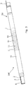
Fig. 1 shows a view of a downhole measuring module in perspective, -
Fig. 2 shows a view of a downhole inflow system in perspective, where the shroud has been removed for illustration purposes, -
Fig. 3 shows the downhole inflow system ofFig. 2 in perspective, where the shroud has not been removed, -
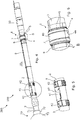
Fig. 4 shows a view of another downhole inflow system in perspective, where the shroud has been removed for illustration purposes, -
Fig. 5 shows an enlarged view of part of the downhole inflow system ofFig. 4 of the communication module, -
Fig. 6 shows an enlarged view of part of the downhole inflow system ofFig. 4 of the downhole measuring module, -
Fig. 7 shows a view of another downhole inflow system in perspective, where the shroud has been removed for illustration purposes, -
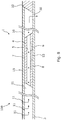
Fig. 8 shows a cross-sectional view of a downhole measuring module, and -
Fig. 9 shows another downhole measuring module in perspective. - All the figures are highly schematic and not necessarily to scale, and they show only those parts which are necessary in order to elucidate the invention, other parts being omitted or merely suggested.
-
Fig. 1 shows adownhole measuring module 1 configured to be mounted on anouter face 2 or as part of a welltubular metal structure 3, as shown inFig. 2 . The welltubular metal structure 3 ofFig. 2 has aninflow section 50 for allowing flow of fluid from areservoir 60 into aborehole 61 in which the well tubular metal structure is arranged. Thedownhole measuring module 1 ofFig. 1 comprises atubular part 4 comprising a plurality offlow channels 5 arranged exterior of the outer face. Thedownhole measuring module 1 further comprises a plurality ofsensors 6 provided in at least some of the flow channels for measuring a condition of the fluid upstream of the inflow section. - As can be seen in
Fig. 1 , thetubular part 4 is mounted from twoparts tubular part 4 may also be a one-piece tubular which is crimped onto theouter face 2 of the welltubular metal structure 3. - The
flow channels 5 are provided in awall 7 of thetubular part 4 and extend along theouter face 2 of the welltubular metal structure 3 and fluidly connect the inflow section and the section on the other side upstream of thedownhole measuring module 1. InFig. 9 , the flow channels aregrooves 17 in thetubular part 4 facing theouter face 2 of the welltubular metal structure 3, and thus thetubular part 4 forms flowchannels 5 together with the welltubular metal structure 3. - The sensors are configured to measure one or more of the following conditions: pressure, conductivity, content, velocity and/or temperature. Thus, the sensors may be pressure sensors, temperature sensors, capacitance sensors, optical probes, Doppler flow meters and/or acoustic sensors. There may be several sensors arranged in one flow channel or one sensor may extend into two flow channels.
- In
Fig. 8 , thedownhole measuring module 1 comprises apower source 8 configured to provide power to thesensors 6. InFig. 2 , thepower source 8 is acontrol line 9 which is anelectrical conductor 9. - The
downhole measuring module 1 forms part of adownhole inflow system 100, as shown inFig. 3 , comprising ashroud 10 mounted exterior of and circumferenting the welltubular metal structure 3 opposite theinflow section 50 forming an annular space 51 (shown inFig. 8 ) between theshroud 10 and the welltubular metal structure 3. Theshroud 10 hasopenings 11 for allowing fluid from the reservoir into the annular space. The shroud is connected with the well tubular metal structure, e.g. by means ofconnection parts 52 as shown inFig. 8 . Thedownhole measuring module 1 is arranged in theannular space 51 between theinflow section 50 and theopenings 11 in theshroud 10, so that all fluid entering through theopenings 11 is guided through theflow channels 5 in thedownhole measuring module 1 before entering into the welltubular metal structure 3 through theinflow section 50. Thedownhole measuring module 1 may further comprise aprocessing unit 53 for processing the measurements from thesensors 6 before these measurements are communicated to surface, so that sufficient information is sent without all measured data being sent. - Thus, the
downhole inflow system 100 further comprises a first communication module configured to communicate data measured by the sensors. Thefirst communication module 41 may be comprised in thedownhole measuring module 1, as shown inFig. 7 . InFig. 4 , thedownhole inflow system 100 comprises thefirst communication module 41 arranged at a distance from thedownhole measuring module 1, so that the fluid flows freely from the openings in the shroud to the downhole measuring module. Thecontrol line 9 electrically connects thedownhole measuring module 1 with thefirst communication module 41 for communicating with and providing power supply to the sensors in thedownhole measuring module 1. As can be seen inFig. 5 , thefirst communication module 41 is arranged between twoconnections 42 connecting thecommunication module 41 with theouter face 2 of the welltubular metal structure 3. Theconnections 42 comprise grooves for allowing fluid to flow past theconnections 42 and thefirst communication module 41. - In
Fig. 7 , thefirst communication module 41 comprises aninductive unit 44 arranged exterior of the welltubular metal structure 3 for conduction of power and/or data through the wall of the welltubular metal structure 3. Theinductive unit 44 comprises acoil wire 45 helically wound around the well tubular metal structure to form acoil 46. - The
first communication module 41 ofFig. 4 is configured to transmit and/or receive power and/or data to/from a wireline tool inside the well tubular metal structure or to/from several second communication modules distributed along the well tubular metal structure to the top of the well and functioning as repeaters to and from a unit arranged near a top of the well tubular metal structure or at surface. - In the event that the
first communication module 41 ofFig. 4 is configured to communicate with a wireline tool, the wireline tool is arranged in the well tubular metal structure in the vicinity of thefirst communication module 41. The wireline tool may have a projectable arm for abutting the inner face of the well tubular metal structure. Thefirst communication module 41 and/or the second communication modules comprise/comprises anacoustic transceiver 47 for transmitting and receiving data and/or power. - As can be seen in
Fig. 6 , theflow channels 5 of thedownhole measuring module 1 are distributed along a periphery of the welltubular metal structure 3 and thecontrol line 9 extends into one of the flow channels. A sensor may be arranged in each of the other flow channels. Thus, each flow channel comprises at least one of the sensors, and some or all flow channels may comprise several sensors. - In
Fig. 8 , thetubular part 4 of thedownhole measuring module 1 has anouter module face 15 abutting theshroud 10. Theouter module face 15 is abutting along the entire circumference of the shroud, so that thedownhole measuring module 1 forms a restriction in theannular space 51 directing all fluid in through the flow channels. - In another embodiment, the shroud has a first shroud part and a second shroud part so that the downhole measuring module in one end is connected to the first shroud part and in another opposing end is connected to the second shroud part, so that all fluid underneath the first shroud part is fluidly connected with the fluid underneath the second shroud part through the flow channels of the downhole measuring module.
- The invention further relates to a
downhole system 200 comprising the well tubular metal structure and one or moredownhole inflow systems 100, as shown inFig. 4 . Thedownhole system 200 further comprisesannular barriers 70 for isolating aproduction zone 101. The annular barrier has atubular unit 71 mounted as part of the well tubular metal structure and anexpandable sleeve 73 surrounding thetubular unit 71 and being connected therewith by means ofconnection parts 72, forming an expandable space there between. The tubular unit has an expansion opening for allowing pressurised fluid from the well tubular metal structure into the space in order to expand theexpandable sleeve 73 and form a barrier towards the inner wall of the borehole or another well tubular metal structure. - Thus, the downhole inflow system guides fluid from the openings in the shroud through the flow channels of the downhole measuring module, and measures at least one condition of the fluid in the flow channels by means of the sensors arranged in at least some of the flow channels upstream of the inflow section. Thus, all fluid is measured upstream of the inflow section, and by directing all fluid in through the flow channels, a more accurate measurement is obtained rather than only performing measurements in one channel, which is e.g. arranged at the top, as the fluid in that channel may comprise more gas than the more heavy oil and thus result in a more inaccurate measurement of the total flow content.
- By fluid or well fluid is meant any kind of fluid that may be present in oil or gas wells downhole, such as natural gas, oil, oil mud, crude oil, water etc. By gas is meant any kind of gas composition present in a well, completion, or open hole, and by oil is meant any kind of oil composition, such as crude oil, an oil-containing fluid etc. Gas, oil, and water fluids may thus all comprise other elements or substances than gas, oil, and/or water, respectively.
- By an annular barrier is meant an annular barrier comprising a tubular metal part mounted as part of the well tubular metal structure and an expandable metal sleeve surrounding and connected to the tubular part defining an annular barrier space.
- By a well tubular metal structure is meant any kind of pipe, casing, tubing, tubular, liner, string etc. used downhole in relation to oil or natural gas production.
- In the event that the tool is not submergible all the way into the casing, a downhole tractor can be used to push the tool all the way into position in the well. The downhole tractor may have projectable arms having wheels, wherein the wheels contact the inner surface of the casing for propelling the tractor and the tool forward in the casing. A downhole tractor is any kind of driving tool capable of pushing or pulling tools in a well downhole, such as a Well Tractor®.
- Although the invention has been described in the above in connection with preferred embodiments of the invention, it will be evident for a person skilled in the art that several modifications are conceivable without departing from the invention as defined by the following claims.
Claims (15)
- A downhole measuring module (1) configured to be mounted on an outer face (2) or as part of a well tubular metal structure (3) having an inflow section (50) for allowing flow of fluid from a reservoir (60) into the well tubular metal structure, said downhole measuring module comprising:- a tubular part (4) comprising a plurality of flow channels (5) arranged exterior of the outer face, and- a plurality of sensors (6) provided in at least some of the flow channels for measuring a condition of the fluid upstream of the inflow section,wherein the flow channels are configured to guide the fluid to flow past the sensors.
- A downhole measuring module according to claim 1, wherein the flow channels are provided in a wall (7) of the tubular part.
- A downhole measuring module according to claim 1, wherein the flow channels are grooves (17) in the tubular parts.
- A downhole measuring module according to any of claims 1-3, wherein the sensors are configured to measure one or more of the conditions: pressure, conductivity, content, velocity and/or temperature.
- A downhole inflow system comprising:- a shroud (10) mounted exterior of and circumferenting a well tubular metal structure (3) opposite an inflow section (50) forming an annular space (51) between the shroud and the well tubular metal structure, the shroud having openings (11) for allowing fluid from a reservoir (60) into the annular space, the shroud being connected with the well tubular metal structure, and- a downhole measuring module (1) according to any of claims 1-4 arranged in the annular space between the inflow section and the openings, so that all fluid entering through the openings is guided through the flow channels in the downhole measuring module before entering into the well tubular metal structure through the inflow section.
- A downhole inflow system according to claim 5, further comprising a first communication module (41) configured to communicate data measured by the sensors.
- A downhole inflow system according to claim 6, further comprising a control line (9) electrically connected with the first communication module for communicating with and providing power supply to the sensors.
- A downhole inflow system according to claim 6, wherein the first communication module comprises an inductive unit (44) arranged exterior of the well tubular metal structure for conducting power and/or data through the well tubular metal structure.
- A downhole inflow system according to claim 6, wherein the first communication module is configured to transmit and/or receive power and/or data to a wireline tool inside the well tubular metal structure.
- A downhole inflow system according to claim 6, further comprising several second communication modules functioning as repeaters to and from a unit arranged near a top of the well tubular metal structure or at surface.
- A downhole inflow system according to claim 9 and/or 10, wherein the first communication module and/or the second communication modules comprise/comprises an acoustic transceiver (47).
- A downhole inflow system according to any of claims 5-11, wherein the flow channels of the downhole measuring module are distributed along a periphery of the well tubular metal structure.
- A downhole inflow system according to any of claims 5-12, wherein each flow channel comprises at least one of the sensors.
- A downhole system (200) comprising a well tubular metal structure (3) and one or more downhole inflow systems (100) according to any of claims 5-13.
- A method for measuring a condition of a fluid downhole, comprising:- providing a downhole inflow system (100) according to any of claims 5-13,- guiding fluid from the openings in the shroud through the flow channels of the downhole measuring module, and- measuring the condition of the fluid in the flow channels by means of the sensors arranged in at least some of the flow channels upstream of the inflow section.
Priority Applications (1)
| Application Number | Priority Date | Filing Date | Title |
|---|---|---|---|
| EP17167532.5A EP3392454A1 (en) | 2017-04-21 | 2017-04-21 | Downhole measuring module and a downhole inflow system |
Applications Claiming Priority (1)
| Application Number | Priority Date | Filing Date | Title |
|---|---|---|---|
| EP17167532.5A EP3392454A1 (en) | 2017-04-21 | 2017-04-21 | Downhole measuring module and a downhole inflow system |
Publications (1)
| Publication Number | Publication Date |
|---|---|
| EP3392454A1 true EP3392454A1 (en) | 2018-10-24 |
Family
ID=58606123
Family Applications (1)
| Application Number | Title | Priority Date | Filing Date |
|---|---|---|---|
| EP17167532.5A Withdrawn EP3392454A1 (en) | 2017-04-21 | 2017-04-21 | Downhole measuring module and a downhole inflow system |
Country Status (1)
| Country | Link |
|---|---|
| EP (1) | EP3392454A1 (en) |
Citations (3)
| Publication number | Priority date | Publication date | Assignee | Title |
|---|---|---|---|---|
| WO2000045031A1 (en) * | 1999-01-29 | 2000-08-03 | Schlumberger Technology Corporation | Controlling production |
| US20090101329A1 (en) * | 2007-10-19 | 2009-04-23 | Baker Hughes Incorporated | Water Sensing Adaptable Inflow Control Device Using a Powered System |
| US20100089141A1 (en) * | 2008-10-14 | 2010-04-15 | Schlumberger Technology Corporation | Downhole annular measurement system and method |
-
2017
- 2017-04-21 EP EP17167532.5A patent/EP3392454A1/en not_active Withdrawn
Patent Citations (3)
| Publication number | Priority date | Publication date | Assignee | Title |
|---|---|---|---|---|
| WO2000045031A1 (en) * | 1999-01-29 | 2000-08-03 | Schlumberger Technology Corporation | Controlling production |
| US20090101329A1 (en) * | 2007-10-19 | 2009-04-23 | Baker Hughes Incorporated | Water Sensing Adaptable Inflow Control Device Using a Powered System |
| US20100089141A1 (en) * | 2008-10-14 | 2010-04-15 | Schlumberger Technology Corporation | Downhole annular measurement system and method |
Similar Documents
| Publication | Publication Date | Title |
|---|---|---|
| US7336199B2 (en) | Inductive coupling system | |
| EP3111032B1 (en) | Electromagnetic directional coupler wired pipe transmission device | |
| US9768546B2 (en) | Wired pipe coupler connector | |
| US9581016B2 (en) | Transmission line for drill pipes and downhole tools | |
| EP2966258B1 (en) | Depth positioning using gamma-ray correlation and downhole parameter differential | |
| US20150123808A1 (en) | Eletric subsurface safety valve with integrated communications system | |
| US9915103B2 (en) | Transmission line for wired pipe | |
| US11131149B2 (en) | Transmission line for wired pipe | |
| CN101291015A (en) | Electromagnetic emitting antenna along with drill, down-hole data communication system and method | |
| US8986028B2 (en) | Wired pipe coupler connector | |
| US9052043B2 (en) | Wired pipe coupler connector | |
| US20190136687A1 (en) | Methods and Systems for Downhole Inductive Coupling | |
| US20140148027A1 (en) | Wired pipe coupler connector | |
| US9874084B2 (en) | Multifunction end cap for coiled tube telemetry | |
| MX2012014486A (en) | Use of wired tubulars for communications/power in an in-riser application. | |
| EP3392454A1 (en) | Downhole measuring module and a downhole inflow system | |
| EP3097249B1 (en) | Wired pipe erosion reduction | |
| US20150194239A1 (en) | Transmission line for wired pipe | |
| US12012846B2 (en) | Borehole geometry sensor and running tool assemblies and methods to deploy a completion component in a lateral bore | |
| US9601237B2 (en) | Transmission line for wired pipe, and method | |
| EP3404204A1 (en) | Downhole surveillance system |
Legal Events
| Date | Code | Title | Description |
|---|---|---|---|
| PUAI | Public reference made under article 153(3) epc to a published international application that has entered the european phase |
Free format text: ORIGINAL CODE: 0009012 |
|
| AK | Designated contracting states |
Kind code of ref document: A1 Designated state(s): AL AT BE BG CH CY CZ DE DK EE ES FI FR GB GR HR HU IE IS IT LI LT LU LV MC MK MT NL NO PL PT RO RS SE SI SK SM TR |
|
| AX | Request for extension of the european patent |
Extension state: BA ME |
|
| STAA | Information on the status of an ep patent application or granted ep patent |
Free format text: STATUS: THE APPLICATION IS DEEMED TO BE WITHDRAWN |
|
| 18D | Application deemed to be withdrawn |
Effective date: 20190425 |