US9601237B2 - Transmission line for wired pipe, and method - Google Patents
Transmission line for wired pipe, and method Download PDFInfo
- Publication number
- US9601237B2 US9601237B2 US14/194,991 US201414194991A US9601237B2 US 9601237 B2 US9601237 B2 US 9601237B2 US 201414194991 A US201414194991 A US 201414194991A US 9601237 B2 US9601237 B2 US 9601237B2
- Authority
- US
- United States
- Prior art keywords
- transmission line
- inner conductor
- wired pipe
- dielectric layer
- protective layer
- Prior art date
- Legal status (The legal status is an assumption and is not a legal conclusion. Google has not performed a legal analysis and makes no representation as to the accuracy of the status listed.)
- Active, expires
Links
- 230000005540 biological transmission Effects 0.000 title claims abstract description 38
- 238000000034 method Methods 0.000 title abstract description 6
- 239000004020 conductor Substances 0.000 claims abstract description 40
- VYPSYNLAJGMNEJ-UHFFFAOYSA-N Silicium dioxide Chemical compound O=[Si]=O VYPSYNLAJGMNEJ-UHFFFAOYSA-N 0.000 claims abstract description 26
- 239000010410 layer Substances 0.000 claims abstract description 24
- 238000005553 drilling Methods 0.000 claims abstract description 20
- 239000000377 silicon dioxide Substances 0.000 claims abstract description 13
- 239000011241 protective layer Substances 0.000 claims abstract description 9
- 239000011810 insulating material Substances 0.000 claims abstract description 7
- 239000000463 material Substances 0.000 claims abstract description 7
- 235000012239 silicon dioxide Nutrition 0.000 claims abstract description 6
- 238000007789 sealing Methods 0.000 claims description 7
- 229910000831 Steel Inorganic materials 0.000 claims description 3
- 239000010959 steel Substances 0.000 claims description 3
- RYGMFSIKBFXOCR-UHFFFAOYSA-N Copper Chemical compound [Cu] RYGMFSIKBFXOCR-UHFFFAOYSA-N 0.000 claims description 2
- 229910052802 copper Inorganic materials 0.000 claims description 2
- 239000010949 copper Substances 0.000 claims description 2
- 238000004519 manufacturing process Methods 0.000 description 7
- 230000008878 coupling Effects 0.000 description 5
- 238000010168 coupling process Methods 0.000 description 5
- 238000005859 coupling reaction Methods 0.000 description 5
- 239000003989 dielectric material Substances 0.000 description 4
- 239000012530 fluid Substances 0.000 description 4
- 230000015572 biosynthetic process Effects 0.000 description 3
- 230000003287 optical effect Effects 0.000 description 3
- 239000004696 Poly ether ether ketone Substances 0.000 description 2
- 230000009286 beneficial effect Effects 0.000 description 2
- 238000004891 communication Methods 0.000 description 2
- -1 for example Substances 0.000 description 2
- 230000007246 mechanism Effects 0.000 description 2
- 229920002530 polyetherether ketone Polymers 0.000 description 2
- 229920001343 polytetrafluoroethylene Polymers 0.000 description 2
- 239000004810 polytetrafluoroethylene Substances 0.000 description 2
- 238000012545 processing Methods 0.000 description 2
- 239000004215 Carbon black (E152) Substances 0.000 description 1
- 229910000881 Cu alloy Inorganic materials 0.000 description 1
- 239000000853 adhesive Substances 0.000 description 1
- 230000001070 adhesive effect Effects 0.000 description 1
- 239000000969 carrier Substances 0.000 description 1
- 239000000919 ceramic Substances 0.000 description 1
- 230000000694 effects Effects 0.000 description 1
- 238000005516 engineering process Methods 0.000 description 1
- 238000011156 evaluation Methods 0.000 description 1
- 229930195733 hydrocarbon Natural products 0.000 description 1
- 150000002430 hydrocarbons Chemical class 0.000 description 1
- 230000001939 inductive effect Effects 0.000 description 1
- 239000012212 insulator Substances 0.000 description 1
- 239000007788 liquid Substances 0.000 description 1
- 238000005259 measurement Methods 0.000 description 1
- 238000012986 modification Methods 0.000 description 1
- 230000004048 modification Effects 0.000 description 1
- 230000008569 process Effects 0.000 description 1
- 239000007787 solid Substances 0.000 description 1
- 238000003466 welding Methods 0.000 description 1
Images


Classifications
-
- H—ELECTRICITY
- H01—ELECTRIC ELEMENTS
- H01B—CABLES; CONDUCTORS; INSULATORS; SELECTION OF MATERIALS FOR THEIR CONDUCTIVE, INSULATING OR DIELECTRIC PROPERTIES
- H01B7/00—Insulated conductors or cables characterised by their form
- H01B7/17—Protection against damage caused by external factors, e.g. sheaths or armouring
- H01B7/28—Protection against damage caused by moisture, corrosion, chemical attack or weather
-
- E—FIXED CONSTRUCTIONS
- E21—EARTH OR ROCK DRILLING; MINING
- E21B—EARTH OR ROCK DRILLING; OBTAINING OIL, GAS, WATER, SOLUBLE OR MELTABLE MATERIALS OR A SLURRY OF MINERALS FROM WELLS
- E21B17/00—Drilling rods or pipes; Flexible drill strings; Kellies; Drill collars; Sucker rods; Cables; Casings; Tubings
- E21B17/003—Drilling rods or pipes; Flexible drill strings; Kellies; Drill collars; Sucker rods; Cables; Casings; Tubings with electrically conducting or insulating means
-
- E—FIXED CONSTRUCTIONS
- E21—EARTH OR ROCK DRILLING; MINING
- E21B—EARTH OR ROCK DRILLING; OBTAINING OIL, GAS, WATER, SOLUBLE OR MELTABLE MATERIALS OR A SLURRY OF MINERALS FROM WELLS
- E21B17/00—Drilling rods or pipes; Flexible drill strings; Kellies; Drill collars; Sucker rods; Cables; Casings; Tubings
- E21B17/02—Couplings; joints
- E21B17/028—Electrical or electro-magnetic connections
- E21B17/0285—Electrical or electro-magnetic connections characterised by electrically insulating elements
-
- H—ELECTRICITY
- H01—ELECTRIC ELEMENTS
- H01B—CABLES; CONDUCTORS; INSULATORS; SELECTION OF MATERIALS FOR THEIR CONDUCTIVE, INSULATING OR DIELECTRIC PROPERTIES
- H01B11/00—Communication cables or conductors
- H01B11/18—Coaxial cables; Analogous cables having more than one inner conductor within a common outer conductor
- H01B11/1895—Particular features or applications
-
- H—ELECTRICITY
- H01—ELECTRIC ELEMENTS
- H01B—CABLES; CONDUCTORS; INSULATORS; SELECTION OF MATERIALS FOR THEIR CONDUCTIVE, INSULATING OR DIELECTRIC PROPERTIES
- H01B7/00—Insulated conductors or cables characterised by their form
- H01B7/16—Rigid-tube cables
-
- H—ELECTRICITY
- H01—ELECTRIC ELEMENTS
- H01R—ELECTRICALLY-CONDUCTIVE CONNECTIONS; STRUCTURAL ASSOCIATIONS OF A PLURALITY OF MUTUALLY-INSULATED ELECTRICAL CONNECTING ELEMENTS; COUPLING DEVICES; CURRENT COLLECTORS
- H01R13/00—Details of coupling devices of the kinds covered by groups H01R12/70 or H01R24/00 - H01R33/00
- H01R13/46—Bases; Cases
- H01R13/533—Bases, cases made for use in extreme conditions, e.g. high temperature, radiation, vibration, corrosive environment, pressure
-
- Y—GENERAL TAGGING OF NEW TECHNOLOGICAL DEVELOPMENTS; GENERAL TAGGING OF CROSS-SECTIONAL TECHNOLOGIES SPANNING OVER SEVERAL SECTIONS OF THE IPC; TECHNICAL SUBJECTS COVERED BY FORMER USPC CROSS-REFERENCE ART COLLECTIONS [XRACs] AND DIGESTS
- Y10—TECHNICAL SUBJECTS COVERED BY FORMER USPC
- Y10T—TECHNICAL SUBJECTS COVERED BY FORMER US CLASSIFICATION
- Y10T29/00—Metal working
- Y10T29/49—Method of mechanical manufacture
- Y10T29/49002—Electrical device making
- Y10T29/49117—Conductor or circuit manufacturing
- Y10T29/49174—Assembling terminal to elongated conductor
Definitions
- a pipe or other conduit is lowered into a borehole in an earth formation during or after drilling operations.
- Such pipes are generally configured as multiple pipe segments to form a “string”, such as a drill string or production string.
- string such as a drill string or production string.
- additional pipe segments are coupled to the string by various coupling mechanisms, such as threaded couplings.
- Pipe segments can be connected with tool joints that include a threaded male-female configuration often referred to as a pin-box connection.
- the pin-box connection includes a male member, i.e., a “pin end” that includes an exterior threaded portion, and a female member, i.e., a “box end”, that includes an interior threaded portion and is configured to receive the pin end in a threaded connection
- Various power and/or communication signals may be transmitted through the pipe segments via a “wired pipe” configuration.
- Such configurations include electrical, optical or other conductors extending along the length of selected pipe segments.
- the conductors are operably connected between pipe segments by a variety of coupling configurations.
- Some wired pipe configurations include a transmission device mounted on the tip of the pin as well as in the box end.
- the transmission device, or “coupler,” can transmit power, data or both to an adjacent coupler.
- the coupler in the pin end might be connected via a coaxial cable to the coupler in the box end.
- the transmission line includes an assembly including an inner conductor and a dielectric layer including silicon dioxide (SiO 2 ) insulating material surrounding the inner conductor and a protective layer that is formed of a rigid material and surrounding the dielectric layer.
- SiO 2 silicon dioxide
- Also disclosed is a method of forming a wired pipe transmission line that includes: providing an assembly that includes an inner conductor surrounded by a silicon dioxide (SiO 2 ) insulating material and a protective layer surrounding the silicon dioxide (SiO 2 ) insulating material; and welding a sealing sleeve to the protective layer at an end of the assembly.
- FIG. 1 depicts an exemplary embodiment of a wired pipe segment of a well drilling and/or logging system
- FIG. 2 depicts an exemplary embodiment of a box end of the segment of FIG. 1 ,
- FIG. 3 depicts an exemplary embodiment of a pin end of the segment of FIG. 1 ;
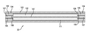
- FIG. 4 shows a cut-away side view of a transmission line according to one embodiment
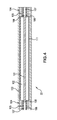
- FIG. 5 shows a transmission line including a sealing sleeve.
- an exemplary embodiment of a portion of a well drilling, logging and/or production system 10 includes a conduit or string 12 , such as a drillstring or production string, that is configured to be disposed in a borehole for performing operations such as drilling the borehole, making measurements of properties of the borehole and/or the surrounding formation downhole, or facilitating gas or liquid production.
- a conduit or string 12 such as a drillstring or production string
- drilling fluid or drilling “mud” is introduced into the string 12 from a source such as a mud tank or “pit” and is circulated under pressure through the string 12 , for example via one or more mud pumps.
- the drilling fluid passes into the string 12 and is discharged at the bottom of the borehole through an opening in a drill bit located at the downhole end of the string 12 .
- the drilling fluid circulates uphole between the string 12 and the borehole wall and is discharged into the mud tank or other location.
- the string 12 may include at least one wired pipe segment 14 having an uphole end 18 and a downhole end 16 .
- uphole refers to a location near the point where the drilling started relative to a reference location when the segment 14 is disposed in a borehole
- downhole refers to a location away from the point where the drilling started along the borehole relative to the reference location. It shall be understood that the uphole end 18 could be below the downhole end 16 without departing from the scope of the disclosure herein.
- a transmission line 22 is located within the wired segment 14 to provide protection for electrical, optical or other conductors which can be part of the transmission line to be disposed along the wired segment 14 .
- the transmission line 22 is a coaxial cable.
- the transmission line 22 is formed of any manner of carrying power or data, including, for example, a twisted pair.
- the transmission line 22 is a coaxial cable it may include an inner conductor surrounded by a dielectric material.
- the coaxial cable may also include a shield layer that surrounds the dielectric.
- the shield layer is electrically coupled to an outer conductor that may be formed, for example, by a rigid or semi-rigid tube of a conductive material.
- the segment 14 includes a downhole connection 24 and an uphole connection 26 .
- the segment 14 is configured so that the uphole connection 26 is positioned at an uphole location relative to the downhole connection 24 .
- the downhole connection 24 includes a male connection portion 28 having an exterior threaded section, and is referred to herein as a “pin end” 24 .
- the uphole connection 26 includes a female connection portion 30 having an interior threaded section, and is referred to herein as a “box end” 26 .
- the pin end 24 and the box end 26 are configured so that the pin end 24 of one wired pipe segment 14 can be disposed within the box end 26 of another wired pipe segment 14 to effect a fixed connection therebetween to connect the segment 14 with another adjacent segment 14 or other downhole component.
- a wired pipe segment may consist of several (e.g. three) segments.
- the exterior of the male coupling portion 28 and the interior of the female coupling portion 30 are tapered.
- the pin end 24 and the box end 26 are described as having threaded portions, the pin end 24 and the box end 26 may be configured to be connected using any suitable mechanism, such as bolts or screws or an interference fit.
- the system 10 is operably connected to a downhole or surface processing unit which may act to control various components of the system 10 , such as drilling, logging and production components or subs. Other components include machinery to raise or lower segments 14 and operably couple segments 14 , and transmission devices.
- the downhole or surface processing unit may also collect and process data generated or transmitted by the system 10 during drilling, production or other operations.
- “drillstring” or “string” refers to any structure or carrier suitable for lowering a tool through a borehole or connecting a drill bit to the surface, and is not limited to the structure and configuration described herein.
- a string could be configured as a drillstring, hydrocarbon production string or formation evaluation string.
- carrier as used herein means any device, device component, combination of devices, media and/or member that may be used to convey, house, support or otherwise facilitate the use of another device, device component, combination of devices, media and/or member.
- Exemplary non-limiting carriers include drill strings of the coiled tube type, of the jointed pipe type and any combination or portion thereof
- Other carrier examples include casing pipes, wirelines, wireline sondes, slickline sondes, drop shots, downhole subs, BHA's and drill strings.
- the segment 14 includes at least one transmission device 34 (also referred to as a “coupler” herein) disposed therein and located at the pin end 24 and/or the box end 26 .
- the transmission device 34 is configured to provide communication of at least one of data and power between adjacent segments 14 when the pin end 24 and the box end 26 are engaged.
- the transmission device 34 may be of any suitable type, such as an inductive coil, capacitive or direct electrical contacts, resonant coupler, or an optical connection ring.
- the coupler may be disposed at the inner or outer shoulder or in between. It shall be understood that the transmission device 34 could also be included in a repeater element disposed between adjacent segments 14 (e.g., within the box end). In such a case, the data/power is transmitted from the transmission device in one segment, into the repeater. The signal may then be passed “as is,” amplified, and/or modified in the repeater and provided to the adjacent segment 14 .
- each transmission device 34 can be connected to one or more transmission lines 22 .
- Embodiments disclosed herein are directed how such transmission lines 22 can be formed.
- a carrier either a dielectric surrounded wire or a twisted pair
- a spirally deformed plate that is wrapped around it.
- FIG. 4 a cut-away side view of a transmission line 22 is illustrated.
- This embodiment includes an inner conductor 101 that may be formed of a solid or braided metallic wire.
- An insulating material such as dielectric layer 102 surrounds the inner conductor 101 for most of the length of the inner conductor 101 .
- a shield layer 111 that surrounds the dielectric layer 102 .
- the shield layer 111 may be formed of a highly conductive material such as copper or a copper alloy in one embodiment. In one embodiment, the shield layer 11 could be a braided layer.
- the combination of the dielectric layer 102 and the inner conductor 101 can be formed in any known manner. In one embodiment, the combination is formed such that the dielectric material 102 and the inner conductor 101 are tightly bound.
- a portion 108 of the inner conductor 101 extend beyond an end of the dielectric layer 102 .
- This portion 108 may be referred to as the inner conductor extension 108 from time to time herein.
- the inner conductor extension 108 provides a contact point for which an electrical connection to the coupler 34 ( FIG. 3 ) can be made.
- the illustrated transmission line 22 includes a connector 104 disposed at the ends of the dielectric layer 102 .
- the connectors 104 serve to provide a means for providing for an electrical connection between the inner conductor 101 and a coupler 34 . It shall be understood that the connectors 104 are optional and can be omitted in one embodiment.
- the connectors 104 include a conductive region 106 that makes physical and electrical contact with the inner conductor 101 .
- the conductive region 106 could be formed, for example, as a metallic tube.
- Surrounding the conductive region 106 is an insulating layer 105 .
- the insulating layer 105 can be formed on any type of insulator including, for example, polyether ether ketone (PEEK), ceramic or a dielectric material.
- an outer conductor 103 surrounds the inner conductor 101 , the dielectric layer 102 and optionally the connectors 104 .
- the outer conductor 103 may be formed a rigid or semi-rigid conducting material around the inner assembly including the inner conductor 101 /dielectric layer 102 and optionally the connectors 104 .
- the outer conductor 103 is formed of steel.
- an adhesive material may be disposed between the inner assembly and the outer conductor 103 to ensure that the inner assembly and the outer conductor 103 do not move relative to one another.
- the inner assembly could be formed in other manners including, for example, as a twisted pair.
- the outer conductor 103 could be formed as a rigid or semi-rigid casing that protects portions that it surrounds.
- the outer conductor 103 may be formed of any type of conductive material and may not provide protection.
- the dielectric material 102 is formed of a silicon dioxide (SiO 2 ).
- the electrical properties of SiO 2 are approximately stable over the range of drilling temperature ranges. Further, using such a material as the dielectric may result in similar electrical properties of a polytetrafluoroethylene (PTFE) cable that is 30-50% smaller and lighter.
- PTFE polytetrafluoroethylene
- the transmission line 22 is formed such that the outer conductor 103 is formed of steel.
- outer conductor 103 could be welded directly to a wired pipe segment or other component.
- the outer conductor is welded to a sealing sleeve 121 .
- the sealing sleeve 121 can be used, for example, to cover a connection from the transmission line 22 to a coupler 34 ( FIG. 3 ) to isolate them from drilling mud.
- the transmission line 22 is held in tension inside the drill pipe. In this case it may be beneficial to weld a load sleeve to the outer conductor 103 to transmit the tension force to the transmission line 22 .
Landscapes
- Engineering & Computer Science (AREA)
- Life Sciences & Earth Sciences (AREA)
- Geology (AREA)
- Mining & Mineral Resources (AREA)
- Mechanical Engineering (AREA)
- Physics & Mathematics (AREA)
- Environmental & Geological Engineering (AREA)
- Fluid Mechanics (AREA)
- General Life Sciences & Earth Sciences (AREA)
- Geochemistry & Mineralogy (AREA)
- Manufacturing & Machinery (AREA)
- Communication Cables (AREA)
Abstract
Description
Claims (5)
Priority Applications (1)
| Application Number | Priority Date | Filing Date | Title |
|---|---|---|---|
| US14/194,991 US9601237B2 (en) | 2014-03-03 | 2014-03-03 | Transmission line for wired pipe, and method |
Applications Claiming Priority (1)
| Application Number | Priority Date | Filing Date | Title |
|---|---|---|---|
| US14/194,991 US9601237B2 (en) | 2014-03-03 | 2014-03-03 | Transmission line for wired pipe, and method |
Publications (2)
| Publication Number | Publication Date |
|---|---|
| US20150248950A1 US20150248950A1 (en) | 2015-09-03 |
| US9601237B2 true US9601237B2 (en) | 2017-03-21 |
Family
ID=54007092
Family Applications (1)
| Application Number | Title | Priority Date | Filing Date |
|---|---|---|---|
| US14/194,991 Active 2034-08-26 US9601237B2 (en) | 2014-03-03 | 2014-03-03 | Transmission line for wired pipe, and method |
Country Status (1)
| Country | Link |
|---|---|
| US (1) | US9601237B2 (en) |
Families Citing this family (1)
| Publication number | Priority date | Publication date | Assignee | Title |
|---|---|---|---|---|
| CN117145461B (en) * | 2023-07-10 | 2024-03-29 | 中国地质大学(武汉) | Wire-while-drilling communication connector, water braid and relay device and communication method |
Citations (16)
| Publication number | Priority date | Publication date | Assignee | Title |
|---|---|---|---|---|
| US3773109A (en) | 1970-10-29 | 1973-11-20 | Kerr Mc Gee Chem Corp | Electrical cable and borehole logging system |
| US3855468A (en) | 1973-12-21 | 1974-12-17 | Texaco Inc | Well logging method and means using an armored multiconductor coaxial cable |
| US3857776A (en) | 1973-06-14 | 1974-12-31 | Electro Petroleum | Deep submersible power electrode assembly for ground conduction of electricity |
| US4139936A (en) | 1977-07-05 | 1979-02-20 | Hughes Aircraft Company | Method of making hermetic coaxial cable |
| US4250351A (en) | 1979-08-08 | 1981-02-10 | The Bendix Corporation | Cable construction |
| US4378464A (en) | 1980-02-25 | 1983-03-29 | Les Cables De Lyon | Cable for prospecting |
| JPH08227620A (en) | 1995-02-21 | 1996-09-03 | Sumitomo Electric Ind Ltd | Coaxial cable and semiconductor device mounting substrate using the same |
| EP0778590A2 (en) | 1995-12-06 | 1997-06-11 | W.L. GORE & ASSOCIATES, INC. | Improvements in or relating to a signal transmission assembly |
| EP1065674A2 (en) | 1999-06-30 | 2001-01-03 | Read Well Services Limited | Downhole cable |
| US6452105B2 (en) | 2000-01-12 | 2002-09-17 | Meggitt Safety Systems, Inc. | Coaxial cable assembly with a discontinuous outer jacket |
| US6982384B2 (en) | 2003-09-25 | 2006-01-03 | Intelliserv, Inc. | Load-resistant coaxial transmission line |
| US7119283B1 (en) | 2005-06-15 | 2006-10-10 | Schlumberger Technology Corp. | Enhanced armor wires for electrical cables |
| US20110042084A1 (en) * | 2009-04-10 | 2011-02-24 | Robert Bos | Irregular pattern treatment of a subsurface formation |
| US20130206748A1 (en) * | 2004-04-23 | 2013-08-15 | Shell Oil Company | Mineral insulated skin effect heating cable |
| US8528651B2 (en) | 2009-10-02 | 2013-09-10 | Baker Hughes Incorporated | Apparatus and method for directionally disposing a flexible member in a pressurized conduit |
| US20140190691A1 (en) * | 2001-10-24 | 2014-07-10 | Harold J. Vinegar | Method of selecting a production well location in a hydrocarbon subsurface formation |
-
2014
- 2014-03-03 US US14/194,991 patent/US9601237B2/en active Active
Patent Citations (16)
| Publication number | Priority date | Publication date | Assignee | Title |
|---|---|---|---|---|
| US3773109A (en) | 1970-10-29 | 1973-11-20 | Kerr Mc Gee Chem Corp | Electrical cable and borehole logging system |
| US3857776A (en) | 1973-06-14 | 1974-12-31 | Electro Petroleum | Deep submersible power electrode assembly for ground conduction of electricity |
| US3855468A (en) | 1973-12-21 | 1974-12-17 | Texaco Inc | Well logging method and means using an armored multiconductor coaxial cable |
| US4139936A (en) | 1977-07-05 | 1979-02-20 | Hughes Aircraft Company | Method of making hermetic coaxial cable |
| US4250351A (en) | 1979-08-08 | 1981-02-10 | The Bendix Corporation | Cable construction |
| US4378464A (en) | 1980-02-25 | 1983-03-29 | Les Cables De Lyon | Cable for prospecting |
| JPH08227620A (en) | 1995-02-21 | 1996-09-03 | Sumitomo Electric Ind Ltd | Coaxial cable and semiconductor device mounting substrate using the same |
| EP0778590A2 (en) | 1995-12-06 | 1997-06-11 | W.L. GORE & ASSOCIATES, INC. | Improvements in or relating to a signal transmission assembly |
| EP1065674A2 (en) | 1999-06-30 | 2001-01-03 | Read Well Services Limited | Downhole cable |
| US6452105B2 (en) | 2000-01-12 | 2002-09-17 | Meggitt Safety Systems, Inc. | Coaxial cable assembly with a discontinuous outer jacket |
| US20140190691A1 (en) * | 2001-10-24 | 2014-07-10 | Harold J. Vinegar | Method of selecting a production well location in a hydrocarbon subsurface formation |
| US6982384B2 (en) | 2003-09-25 | 2006-01-03 | Intelliserv, Inc. | Load-resistant coaxial transmission line |
| US20130206748A1 (en) * | 2004-04-23 | 2013-08-15 | Shell Oil Company | Mineral insulated skin effect heating cable |
| US7119283B1 (en) | 2005-06-15 | 2006-10-10 | Schlumberger Technology Corp. | Enhanced armor wires for electrical cables |
| US20110042084A1 (en) * | 2009-04-10 | 2011-02-24 | Robert Bos | Irregular pattern treatment of a subsurface formation |
| US8528651B2 (en) | 2009-10-02 | 2013-09-10 | Baker Hughes Incorporated | Apparatus and method for directionally disposing a flexible member in a pressurized conduit |
Non-Patent Citations (1)
| Title |
|---|
| Times Microwave Systems, "Si02 Coaxial Cable Assemblies", Sep. 2007, [retrieved on Oct. 29, 2013]. Retrieved from the internet: URL:http://www.timesmicrowave.com/downloads/products/sio2-single-pages.pdf, 4 pages. |
Also Published As
| Publication number | Publication date |
|---|---|
| US20150248950A1 (en) | 2015-09-03 |
Similar Documents
| Publication | Publication Date | Title |
|---|---|---|
| US10404007B2 (en) | Wired pipe coupler connector | |
| US10760349B2 (en) | Method of forming a wired pipe transmission line | |
| US11131149B2 (en) | Transmission line for wired pipe | |
| US9228686B2 (en) | Transmission line for drill pipes and downhole tools | |
| US8986028B2 (en) | Wired pipe coupler connector | |
| US9052043B2 (en) | Wired pipe coupler connector | |
| US20140148027A1 (en) | Wired pipe coupler connector | |
| US20160049718A1 (en) | Wired pipe coupler connector | |
| US9725963B2 (en) | Transmission line for wired pipe | |
| US20190218864A1 (en) | Wired pipe surface sub | |
| US9601237B2 (en) | Transmission line for wired pipe, and method | |
| US20150194239A1 (en) | Transmission line for wired pipe | |
| EP3097249B1 (en) | Wired pipe erosion reduction |
Legal Events
| Date | Code | Title | Description |
|---|---|---|---|
| AS | Assignment |
Owner name: BAKER HUGHES INCORPORATED, TEXAS Free format text: ASSIGNMENT OF ASSIGNORS INTEREST;ASSIGNORS:MUELLER, STEPHAN;RODERS, INGO;SCHULZ, RENE;AND OTHERS;SIGNING DATES FROM 20140324 TO 20140407;REEL/FRAME:032628/0762 |
|
| STCF | Information on status: patent grant |
Free format text: PATENTED CASE |
|
| AS | Assignment |
Owner name: BHGE VENTURES & GROWTH LLC, OKLAHOMA Free format text: NUNC PRO TUNC ASSIGNMENT;ASSIGNOR:BAKER HUGHES OILFIELD OPERATIONS LLC;REEL/FRAME:047778/0861 Effective date: 20181213 |
|
| AS | Assignment |
Owner name: NEXTSTREAM WIRED PIPE, LLC, OKLAHOMA Free format text: ASSIGNMENT OF ASSIGNORS INTEREST;ASSIGNOR:BHGE VENTURES & GROWTH, LLC;REEL/FRAME:048093/0118 Effective date: 20190122 |
|
| AS | Assignment |
Owner name: BAKER HUGHES, A GE COMPANY, LLC, TEXAS Free format text: CHANGE OF NAME;ASSIGNOR:BAKER HUGHES INCORPORATED;REEL/FRAME:048356/0318 Effective date: 20170703 |
|
| AS | Assignment |
Owner name: BAKER HUGHES OILFIELD OPERATIONS LLC, TEXAS Free format text: ASSIGNMENT OF ASSIGNORS INTEREST;ASSIGNOR:BAKER HUGHES, A GE COMPANY, LLC;REEL/FRAME:048504/0382 Effective date: 20181009 |
|
| AS | Assignment |
Owner name: NEXTSTREAM WIRED PIPE, LLC, OKLAHOMA Free format text: CORRECTIVE ASSIGNMENT TO CORRECT THE NAME OF THE ASSIGNEE ON PAGE 2 ABOVE SIGNATURE PREVIOUSLY RECORDED AT REEL: 048093 FRAME: 0118. ASSIGNOR(S) HEREBY CONFIRMS THE ASSIGNMENT;ASSIGNOR:BHGE VENTURES & GROWTH, LLC;REEL/FRAME:049008/0318 Effective date: 20190122 |
|
| MAFP | Maintenance fee payment |
Free format text: PAYMENT OF MAINTENANCE FEE, 4TH YEAR, LARGE ENTITY (ORIGINAL EVENT CODE: M1551); ENTITY STATUS OF PATENT OWNER: LARGE ENTITY Year of fee payment: 4 |
|
| MAFP | Maintenance fee payment |
Free format text: PAYMENT OF MAINTENANCE FEE, 8TH YEAR, LARGE ENTITY (ORIGINAL EVENT CODE: M1552); ENTITY STATUS OF PATENT OWNER: LARGE ENTITY Year of fee payment: 8 |