EP3392126A1 - Saddle device - Google Patents
Saddle device Download PDFInfo
- Publication number
- EP3392126A1 EP3392126A1 EP17191980.6A EP17191980A EP3392126A1 EP 3392126 A1 EP3392126 A1 EP 3392126A1 EP 17191980 A EP17191980 A EP 17191980A EP 3392126 A1 EP3392126 A1 EP 3392126A1
- Authority
- EP
- European Patent Office
- Prior art keywords
- unit
- saddles
- toothed members
- seat unit
- saddle
- Prior art date
- Legal status (The legal status is an assumption and is not a legal conclusion. Google has not performed a legal analysis and makes no representation as to the accuracy of the status listed.)
- Granted
Links
Images


Classifications
-
- B—PERFORMING OPERATIONS; TRANSPORTING
- B62—LAND VEHICLES FOR TRAVELLING OTHERWISE THAN ON RAILS
- B62J—CYCLE SADDLES OR SEATS; AUXILIARY DEVICES OR ACCESSORIES SPECIALLY ADAPTED TO CYCLES AND NOT OTHERWISE PROVIDED FOR, e.g. ARTICLE CARRIERS OR CYCLE PROTECTORS
- B62J1/00—Saddles or other seats for cycles; Arrangement thereof; Component parts
- B62J1/10—Internal adjustment of saddles
-
- B—PERFORMING OPERATIONS; TRANSPORTING
- B62—LAND VEHICLES FOR TRAVELLING OTHERWISE THAN ON RAILS
- B62J—CYCLE SADDLES OR SEATS; AUXILIARY DEVICES OR ACCESSORIES SPECIALLY ADAPTED TO CYCLES AND NOT OTHERWISE PROVIDED FOR, e.g. ARTICLE CARRIERS OR CYCLE PROTECTORS
- B62J1/00—Saddles or other seats for cycles; Arrangement thereof; Component parts
- B62J1/005—Saddles having a seating area with multiple separate weight bearing surfaces
-
- B—PERFORMING OPERATIONS; TRANSPORTING
- B62—LAND VEHICLES FOR TRAVELLING OTHERWISE THAN ON RAILS
- B62J—CYCLE SADDLES OR SEATS; AUXILIARY DEVICES OR ACCESSORIES SPECIALLY ADAPTED TO CYCLES AND NOT OTHERWISE PROVIDED FOR, e.g. ARTICLE CARRIERS OR CYCLE PROTECTORS
- B62J1/00—Saddles or other seats for cycles; Arrangement thereof; Component parts
- B62J1/007—Saddles with specific anatomical adaptations
-
- B—PERFORMING OPERATIONS; TRANSPORTING
- B62—LAND VEHICLES FOR TRAVELLING OTHERWISE THAN ON RAILS
- B62J—CYCLE SADDLES OR SEATS; AUXILIARY DEVICES OR ACCESSORIES SPECIALLY ADAPTED TO CYCLES AND NOT OTHERWISE PROVIDED FOR, e.g. ARTICLE CARRIERS OR CYCLE PROTECTORS
- B62J1/00—Saddles or other seats for cycles; Arrangement thereof; Component parts
- B62J1/08—Frames for saddles; Connections between saddle frames and seat pillars; Seat pillars
-
- B—PERFORMING OPERATIONS; TRANSPORTING
- B62—LAND VEHICLES FOR TRAVELLING OTHERWISE THAN ON RAILS
- B62J—CYCLE SADDLES OR SEATS; AUXILIARY DEVICES OR ACCESSORIES SPECIALLY ADAPTED TO CYCLES AND NOT OTHERWISE PROVIDED FOR, e.g. ARTICLE CARRIERS OR CYCLE PROTECTORS
- B62J1/00—Saddles or other seats for cycles; Arrangement thereof; Component parts
- B62J1/28—Other additional equipment, e.g. back-rests for children
-
- B—PERFORMING OPERATIONS; TRANSPORTING
- B62—LAND VEHICLES FOR TRAVELLING OTHERWISE THAN ON RAILS
- B62J—CYCLE SADDLES OR SEATS; AUXILIARY DEVICES OR ACCESSORIES SPECIALLY ADAPTED TO CYCLES AND NOT OTHERWISE PROVIDED FOR, e.g. ARTICLE CARRIERS OR CYCLE PROTECTORS
- B62J9/00—Containers specially adapted for cycles, e.g. panniers or saddle bags
- B62J9/20—Containers specially adapted for cycles, e.g. panniers or saddle bags attached to the cycle as accessories
- B62J9/26—Containers specially adapted for cycles, e.g. panniers or saddle bags attached to the cycle as accessories to the saddle, e.g. saddle bags
Definitions
- the disclosure relates to a bicycle member, and more particularly to a saddle device that is mounted to a bicycle frame.
- a conventional saddle device disclosed in U.S. Patent No. 694,875 includes a bottom seat, a shaft rod mounted to the bottom seat, and two saddles threadedly connected to the shaft rod.
- Each of the saddles has a front end portion, and a rear end portion opposite to the front end portion, and disposed for mounting the shaft rod.
- Two ends of the shaft rod respectively have a right-handed thread section and a left-handed thread section.
- the saddles are respectively and threadedly connected to the right-handed thread section and the left-handed thread section of the shaft rod.
- the right-handed thread section and the left-handed thread section cooperate to drive a relative movement between the saddles for adjusting a distance between the saddles.
- the conventional saddle device can adjust the distance between the saddles, for most of bicycles, a portion of a bicycle for mounting the saddles is fixed such that, the positions of the saddles in a front-rear direction are not adjustable for different users.
- a user usually requires some repair tools and repair members for repairing the bicycle, and usually needs to bring a wallet, since the structure of the bicycle frame is simple, it is difficult to mount a bag on a bicycle frame near a saddle portion of the bicycle for receiving the repair tools, the repair members and the wallet.
- the conventional saddle device disclosed in U.S. Patent No. 694,875 does not include a coupling structure for mounting a saddle bag, and a backrest structure for supporting the back of the user.
- the object of the disclosure is to provide a saddle device that can be adjusted based on the requirement of a user.
- the saddle device includes a first seat unit, a second seat unit, a saddle unit, a supporting member and a backrest.
- the first seat unit has a track portion extending in a front-rear direction.
- the second seat unit is mounted to and disposed behind the first seat unit, and is movable on the first seat unit in the front-rear direction.
- the saddle unit is mounted to the second seat unit, and has a top surface unit.
- the supporting member is connected to the first seat unit, has a rear mounting end portion distal from the first seat unit and disposed behind the second seat unit, and is transformable between a lifted position and a lowered position such that, when the supporting member is at the lifted position, the rear mounting end portion is located above the top surface unit of the saddle unit, and when the supporting member is at the lowered position, the rear mounting end portion is located below the top surface unit of the saddle unit.
- the backrest is mountable to the rear mounting end portion when the supporting member is at the lifted position, such that the backrest is disposed behind the saddle unit.
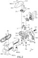
- the first embodiment of a saddle device is adapted to be mounted to a seat post 100, and includes a first seat unit 10 connected to a top portion of the seat post 100, a second seat unit 20, a saddle unit 30, a supporting member 40, a backrest 50, an adjusting unit 60 and a reinforcing frame member 70.
- the first seat unit 10 has a track portion 11 extending in a front-rear direction (X), and a front mounting portion 12 disposed in front of the track portion 11.
- the track portion 11 has a non-circular cross section taken perpendicular to the front-rear direction (X). In this embodiment, the track portion 11 has an 8-shaped cross section, and may be varied in other embodiments.
- the track portion 11 has a rear end surface 111, and two engaging holes 112 formed in the rear end surface 111, and extending in the front-rear direction (X) .
- the front mounting portion 12 has an engaging groove 121 formed in a top surface thereof.
- the second seat unit 20 is mounted to and disposed behind the first seat unit 10, and is movable on the track portion 11 of the first seat unit 10 in the front-rear direction (X).
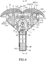
- the second seat unit 20 includes a main body 21, two bolts 22 extending through the main body 21, two toothed members 23 mounted to the main body 21, and a resilient positioning member 24 mounted to the main body 21.
- the main body 21 has an upper surface 211, a receiving groove 212 formed in the upper surface 211, and extending in a left-right direction which is perpendicular to the front-rear direction (X), and two positioning seats 213 fixedly disposed in the receiving groove 212.
- Each of the positioning seats 213 is formed with a through hole 214 extending along an axis (L) which is perpendicular to the front-rear direction (X).
- the bolts 22 respectively extend through the through holes 214 of the positioning seats 213.
- Each of the bolts 22 has a head portion 221 abutting against a bottom portion of the main body 21, and a threaded portion 222 extending through the corresponding through hole 214.
- Each of the toothed members 23 is mounted to the main body 21, is rotatable about a respective one of the axes (L) of the toothed members 23, and has an annular portion 231, an interacting portion 232 integrally connected to the annular portion 231, a lower crown gear portion 233 disposed at a top portion of the annular portion 231, and centered at a corresponding one of the axes (L), a plurality of finger-shaped teeth 234 formed on one end of the interacting portion 232 that is distal from the annular portion 231, and a plurality of positioning grooves 235 formed in one end of the interacting portion 232 that is distal from the annular portion 231, and disposed under the finger-shaped teeth 234.
- the finger-shaped teeth 234 of one of the toothed members 23 mesh with the finger-shaped teeth 234 of the other one of the toothed members 23 (see Figure 3 ), such that when the one of the toothed members 23 rotates in a direction, the other one of the toothed members 23 rotates in an opposite direction.
- the resilient positioning member 24 is inverted U-shaped, and has two lower ends abutting against the main body 21, and an engaging portion 241 biased to press against one of the toothed members 23, and engaging one of the positioning grooves 235 of the one of the toothed members 23.
- the engaging portion 241 protrudes upwardly from a middle portion of the resilient positioning member 24, and such configuration may be varied in other embodiments.
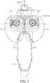
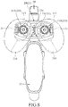
- the saddle unit 30 is mounted to the second seat unit 20, and includes two saddles 31 respectively corresponding to the toothed members 23 in position.
- Each of the saddles 31 has an upper end portion having a flat top surface 311, a lower end portion 312 opposite to the upper end portion, a rear end edge 313, a front end edge 314 opposite to the rear end edge 313, an upper crown gear portion 315 disposed at the lower end portion 312, and coaxial with the lower crown gear portion 233 of a corresponding one of the toothed members 23, and a rod segment 316 extending along the corresponding one of the axes (L), and rotatably extending through the annular portion 231 of the corresponding one of the toothed members 23.
- the flat top surfaces 311 of the saddles 31 cooperately form a top surface unit 32.
- Each of the rod segments 316 of the saddles 31 has a threaded hole 317.
- the upper crown gear portion 315 of each of the saddles 31 is disposed coaxially with a corresponding one of the threaded holes 317.
- the bolts 22 respectively and threadedly engage the threaded holes 317 of the saddles 31, so as to allow the lower crown gear portions 233 of the toothed members 23 to respectively engage the upper crown gear portions 315 of the saddles 31, thereby allowing the saddles 31 to respectively co-rotate with the toothed members 23, such that each of the bolts 22 is rotatable to allow for an adjustment to angular position of a corresponding one of the saddles 31 relative to a corresponding one of the toothed members 23.
- a distance between the front end edge 314 and the axis (L) is larger than a distance between the rear end edge 313 and the axis (L) .
- each of the saddles 31 meshes with the lower crown gear portion 233 of the corresponding one of the toothed members 23, such that each of the saddles 31 is rotatable relative to the corresponding one of the toothed members 23 about the corresponding one of the axes (L) of the toothed members 23 for adjusting a distance between the rear end edges 313 of the saddles 31 and a distance between the front end edges 314 of the saddles 31.
- the supporting member 40 is connected to the first seat unit 10, and has a coupling end 41, and a rear mounting end portion 42 opposite to the coupling end 41 and disposed behind the second seat unit 20, and distal from the first seat unit 10.
- the coupling end 41 has a coupling groove 411 corresponding to the cross section of the track portion 11 in shape, and engaged with the track portion 11, and a locking hole 412 communicated with the coupling groove 411.
- the supporting member 40 includes a screw 413 extending through the locking hole 412 and into the coupling groove 411 to threadedly engage one of the engaging holes 112 of the track portion 11.
- the rear mounting end portion 42 has two mounting holes 421 juxtaposed in a direction which is parallel to the axes (L), and two fastening holes 422 respectively communicated with the mounting holes 421.
- the shape of each of the mounting holes 421 is rectangular, and may be varied in other embodiments.
- the backrest 50 has a connecting block 51 having a backrest threaded hole 511.
- the adjusting unit 60 is mounted between the first seat unit 10 and the second seat unit 20, and includes a rack 61 extending in the front-rear direction (X), and mounted to the track portion 11 of the first seat unit 10, and a worm 62 mounted to the main body 21 of the second seat unit 20, and meshing with the rack 61 (see Figure 5 ).
- the worm 62 has a hexagonal hole 621 disposed for being engaged by a hex key wrench (not shown). The hex key wrench is operable to rotate the worm 62 to drive a relative movement between the first and second seat units 10, 20 in the front-rear direction (X).
- the reinforcing frame member 70 has a U-shaped rod part 71 adapted to be disposed around the seat post 100, and a connecting rod part 72 connected to the U-shaped rod part 71, and securely inserted into the first seat unit 10.
- the supporting member 40 is transformable between a lifted position (see Figure 6 ) and a lowered position (see Figure 1 ) such that, when the supporting member 40 is at the lifted position, the rear mounting end portion 42 is located above the top surface unit 32 of the saddle unit 30, and when the supporting member 40 is at the lowered position, the rear mounting end portion 42 is located below the top surface unit 32 of the saddle unit 30.
- the backrest 50 is mountable to the rear mounting end portion 42 when the supporting member 40 is at the lifted position, such that the backrest 50 is disposed behind the saddle unit 30, and is mountable to the front mounting portion 12 when the supporting member 40 is at the lowered position, such that the backrest 50 is disposed in front of the saddle unit 30.
- a screw extends through a corresponding one of the fastening holes 422, and threadedly engages the backrest threaded hole 511 to fasten the backrest 50 to the supporting member 40.
- the connecting block 51 engages the engaging groove 121 of the front mounting portion 12.
- a saddle bag 200 which is disposed for receiving repairing tools, repairing members and a wallet is fastened to the rear mounting end portion 42 by a screw (not shown) .
- the backrest 50 is fastened to the front mounting portion 12 by a screw, such that the backrest 50 is prevented from being removed from the front mounting portion 12. Therefore, the disposition of the backrest 50 not only increases the support to the saddle unit 30, but also reduces the space occupied when it is not used.
- the supporting member 40 When the supporting member 40 is required to transform from the lowered position to the lifted position, a user firstly needs to remove the saddle bag 200, then operates the screw 413 to remove the supporting member 40 from the track portion 11. The supporting member 40 is then flipped 180 degrees relative to the first seat unit 10, and is subsequently mounted back to the track portion 11. As shown in Figure 6 , at the lifted position, the backrest 50 can be mounted to the rear mounting end portion 42 for supporting the back of the user. Since the backrest 50 is fastened to the rear mounting end portion 42 by the screw, the backrest 50 is prevented from being removed from the supporting member 40.
- the user needs to rotate one of the saddles 31.
- the upper crown gear portion 315 of the one of the saddles 31 co-rotates with the lower crown gear portion 233 of the corresponding one of the toothed members 23, such that the corresponding one of the toothed members 23 is simultaneously rotated by the one of the saddles 31.
- the finger-shaped teeth 234 of the corresponding one of the toothed members 23 meshes with the finger-shaped teeth 234 of the other one of the toothed members 23, such that the other one of the saddles is driven to rotate in an opposite direction.
- the positioning grooves 235 rotate relative to the engaging portion 241 of the resilient positioning member 24, so that a clicking sound is generated until the saddles 31 stop to rotate. Since the engaging portion 241 engages the corresponding one of the positioning grooves 235, the positions of the toothed members 23 are fixed relative to the main body 21, and the saddles 31 are also positioned.
- the user may rotate the bolts 22 first so that, when one of the saddles 31 is rotated by the user, the one of the saddles 31 is rotated relative to a corresponding one of the toothed members 23, the angular position of the one of the saddles 31 relative to the corresponding one of the toothed members 23 is adjusted, and the distance between the rear end edges 313 of the saddles 31 and the distance between the front end edges 314 of the saddles 31 are also adjusted.
- the position of the supporting member 40, the position of the second seat unit 20 and the saddle unit 30 on the track portion 11, and the distance between the rear end edges 313 of the saddles 31 and the distance between the front end edges 314 of the saddles 31 are adjustable by the user to meet the operation requirements.
- the shape of the saddles 31 may be varied based on different physiological conditions in other embodiments.
- the second embodiment of the saddle device according to the disclosure has a structure similar to that of the first embodiment.
- the main difference between this embodiment and the previous embodiment resides in the configuration of the second seat unit 20'.
- the second seat unit 20' includes a main body 21' having a receiving groove 212' that extends in the left-right direction which is perpendicular to the front-rear direction (X), two bolts 22' extending through the main body 21', and two toothed members 23' non-rotatably mounted to the main body 21' .
- Each of the toothed members 23' has an annular portion 231', two engaging blocks 232' connected to a bottom portion of the annular portion 231', and engaging the receiving groove 212' such that they cannot be rotated within the receiving grooves 212' , and a lower crown gear portion 233' disposed at a top portion of the annular portion 231' , and centered at an axis (L).
- the upper crown gear portions 315 of the saddles 31 respectively mesh with the lower crown gear portion 233' of the toothed members 23'.
- the corresponding bolt 22 When the user needs to adjust the angular position of one of the saddles 31, the corresponding bolt 22 is loosened such that it remains in the corresponding threaded hole 317 of the corresponding saddle 31, and the one of the saddles 31 is removed from and rotated relative to the corresponding toothed member 23 to adjust the angular position of the one of the saddles 31. After the adjustment is completed, the corresponding bolt 22 is tightened such that the corresponding upper and lower crown gears 315, 233' mesh with each other, thereby maintaining the angular position of the one of the saddles 31.
- the second embodiment has the same advantages as those of the first embodiment, and therefore the operation requirements also can be met.
Landscapes
- Engineering & Computer Science (AREA)
- Mechanical Engineering (AREA)
- Chairs For Special Purposes, Such As Reclining Chairs (AREA)
- Chair Legs, Seat Parts, And Backrests (AREA)
- Seats For Vehicles (AREA)
Abstract
Description
- The disclosure relates to a bicycle member, and more particularly to a saddle device that is mounted to a bicycle frame.
- A conventional saddle device disclosed in
U.S. Patent No. 694,875 includes a bottom seat, a shaft rod mounted to the bottom seat, and two saddles threadedly connected to the shaft rod. Each of the saddles has a front end portion, and a rear end portion opposite to the front end portion, and disposed for mounting the shaft rod. Two ends of the shaft rod respectively have a right-handed thread section and a left-handed thread section. The saddles are respectively and threadedly connected to the right-handed thread section and the left-handed thread section of the shaft rod. - When the shaft rod rotates, the right-handed thread section and the left-handed thread section cooperate to drive a relative movement between the saddles for adjusting a distance between the saddles.
- Even if the conventional saddle device can adjust the distance between the saddles, for most of bicycles, a portion of a bicycle for mounting the saddles is fixed such that, the positions of the saddles in a front-rear direction are not adjustable for different users.
- In addition, a user usually requires some repair tools and repair members for repairing the bicycle, and usually needs to bring a wallet, since the structure of the bicycle frame is simple, it is difficult to mount a bag on a bicycle frame near a saddle portion of the bicycle for receiving the repair tools, the repair members and the wallet.
- Moreover, the conventional saddle device disclosed in
U.S. Patent No. 694,875 does not include a coupling structure for mounting a saddle bag, and a backrest structure for supporting the back of the user. - Therefore, the object of the disclosure is to provide a saddle device that can be adjusted based on the requirement of a user.
- According to the disclosure, the saddle device includes a first seat unit, a second seat unit, a saddle unit, a supporting member and a backrest. The first seat unit has a track portion extending in a front-rear direction. The second seat unit is mounted to and disposed behind the first seat unit, and is movable on the first seat unit in the front-rear direction. The saddle unit is mounted to the second seat unit, and has a top surface unit. The supporting member is connected to the first seat unit, has a rear mounting end portion distal from the first seat unit and disposed behind the second seat unit, and is transformable between a lifted position and a lowered position such that, when the supporting member is at the lifted position, the rear mounting end portion is located above the top surface unit of the saddle unit, and when the supporting member is at the lowered position, the rear mounting end portion is located below the top surface unit of the saddle unit. The backrest is mountable to the rear mounting end portion when the supporting member is at the lifted position, such that the backrest is disposed behind the saddle unit.
- Other features and advantages of the disclosure will become apparent in the following detailed description of the embodiments with reference to the accompanying drawings, of which:
-
Figure 1 is a perspective view of a first embodiment of a saddle device according to the disclosure; -
Figure 2 is a partly exploded perspective view of the first embodiment; -
Figure 3 is another partly exploded perspective view of the first embodiment; -
Figure 4 is a sectional view taken along line IV-IV inFigure 3 ; -
Figure 5 is a sectional view taken along line V-V inFigure 4 ; -
Figure 6 is a schematic perspective view of the first embodiment, and illustrates that a supporting member is at a lifted position, and a backrest is mounted to the supporting member; -
Figure 7 is a schematic top view of the first embodiment; -
Figure 8 is a view similar toFigure 7 but illustrating position adjustment of two saddles; -
Figure 9 is a partly exploded perspective view of a second embodiment of the saddle device according to the disclosure; and -
Figure 10 is a sectional view of the second embodiment. - Before the disclosure is described in greater detail, it should be noted that where considered appropriate, reference numerals or terminal portions of reference numerals have been repeated among the figures to indicate corresponding or analogous elements, which may optionally have similar characteristics.
- Referring to
Figures 1 ,2 ,4 and5 , the first embodiment of a saddle device according to the disclosure is adapted to be mounted to aseat post 100, and includes afirst seat unit 10 connected to a top portion of theseat post 100, asecond seat unit 20, asaddle unit 30, a supportingmember 40, abackrest 50, an adjustingunit 60 and a reinforcingframe member 70. - The
first seat unit 10 has atrack portion 11 extending in a front-rear direction (X), and afront mounting portion 12 disposed in front of thetrack portion 11. Thetrack portion 11 has a non-circular cross section taken perpendicular to the front-rear direction (X). In this embodiment, thetrack portion 11 has an 8-shaped cross section, and may be varied in other embodiments. Thetrack portion 11 has arear end surface 111, and twoengaging holes 112 formed in therear end surface 111, and extending in the front-rear direction (X) . Thefront mounting portion 12 has anengaging groove 121 formed in a top surface thereof. - The
second seat unit 20 is mounted to and disposed behind thefirst seat unit 10, and is movable on thetrack portion 11 of thefirst seat unit 10 in the front-rear direction (X). Thesecond seat unit 20 includes amain body 21, twobolts 22 extending through themain body 21, twotoothed members 23 mounted to themain body 21, and aresilient positioning member 24 mounted to themain body 21. - The
main body 21 has anupper surface 211, areceiving groove 212 formed in theupper surface 211, and extending in a left-right direction which is perpendicular to the front-rear direction (X), and twopositioning seats 213 fixedly disposed in thereceiving groove 212. Each of thepositioning seats 213 is formed with a throughhole 214 extending along an axis (L) which is perpendicular to the front-rear direction (X). - The
bolts 22 respectively extend through the throughholes 214 of thepositioning seats 213. Each of thebolts 22 has ahead portion 221 abutting against a bottom portion of themain body 21, and a threadedportion 222 extending through the corresponding throughhole 214. - Each of the
toothed members 23 is mounted to themain body 21, is rotatable about a respective one of the axes (L) of thetoothed members 23, and has anannular portion 231, an interactingportion 232 integrally connected to theannular portion 231, a lowercrown gear portion 233 disposed at a top portion of theannular portion 231, and centered at a corresponding one of the axes (L), a plurality of finger-shaped teeth 234 formed on one end of the interactingportion 232 that is distal from theannular portion 231, and a plurality ofpositioning grooves 235 formed in one end of the interactingportion 232 that is distal from theannular portion 231, and disposed under the finger-shaped teeth 234. The finger-shaped teeth 234 of one of thetoothed members 23 mesh with the finger-shaped teeth 234 of the other one of the toothed members 23 (seeFigure 3 ), such that when the one of thetoothed members 23 rotates in a direction, the other one of thetoothed members 23 rotates in an opposite direction. - The
resilient positioning member 24 is inverted U-shaped, and has two lower ends abutting against themain body 21, and anengaging portion 241 biased to press against one of thetoothed members 23, and engaging one of thepositioning grooves 235 of the one of thetoothed members 23. In this embodiment, theengaging portion 241 protrudes upwardly from a middle portion of theresilient positioning member 24, and such configuration may be varied in other embodiments. - The
saddle unit 30 is mounted to thesecond seat unit 20, and includes twosaddles 31 respectively corresponding to thetoothed members 23 in position. Each of thesaddles 31 has an upper end portion having aflat top surface 311, alower end portion 312 opposite to the upper end portion, arear end edge 313, afront end edge 314 opposite to therear end edge 313, an uppercrown gear portion 315 disposed at thelower end portion 312, and coaxial with the lowercrown gear portion 233 of a corresponding one of thetoothed members 23, and arod segment 316 extending along the corresponding one of the axes (L), and rotatably extending through theannular portion 231 of the corresponding one of thetoothed members 23. Theflat top surfaces 311 of thesaddles 31 cooperately form atop surface unit 32. Each of therod segments 316 of thesaddles 31 has a threadedhole 317. The uppercrown gear portion 315 of each of thesaddles 31 is disposed coaxially with a corresponding one of the threadedholes 317. Thebolts 22 respectively and threadedly engage the threadedholes 317 of thesaddles 31, so as to allow the lowercrown gear portions 233 of thetoothed members 23 to respectively engage the uppercrown gear portions 315 of thesaddles 31, thereby allowing thesaddles 31 to respectively co-rotate with thetoothed members 23, such that each of thebolts 22 is rotatable to allow for an adjustment to angular position of a corresponding one of thesaddles 31 relative to a corresponding one of thetoothed members 23. For each of thesaddles 31, a distance between thefront end edge 314 and the axis (L) is larger than a distance between therear end edge 313 and the axis (L) . The uppercrown gear portion 315 of each of thesaddles 31 meshes with the lowercrown gear portion 233 of the corresponding one of thetoothed members 23, such that each of thesaddles 31 is rotatable relative to the corresponding one of thetoothed members 23 about the corresponding one of the axes (L) of thetoothed members 23 for adjusting a distance between therear end edges 313 of thesaddles 31 and a distance between thefront end edges 314 of thesaddles 31. - The supporting
member 40 is connected to thefirst seat unit 10, and has acoupling end 41, and a rearmounting end portion 42 opposite to thecoupling end 41 and disposed behind thesecond seat unit 20, and distal from thefirst seat unit 10. Thecoupling end 41 has acoupling groove 411 corresponding to the cross section of thetrack portion 11 in shape, and engaged with thetrack portion 11, and alocking hole 412 communicated with thecoupling groove 411. The supportingmember 40 includes ascrew 413 extending through thelocking hole 412 and into thecoupling groove 411 to threadedly engage one of theengaging holes 112 of thetrack portion 11. The rearmounting end portion 42 has twomounting holes 421 juxtaposed in a direction which is parallel to the axes (L), and twofastening holes 422 respectively communicated with themounting holes 421. In this embodiment, the shape of each of themounting holes 421 is rectangular, and may be varied in other embodiments. - The
backrest 50 has a connectingblock 51 having a backrest threadedhole 511. - The adjusting
unit 60 is mounted between thefirst seat unit 10 and thesecond seat unit 20, and includes arack 61 extending in the front-rear direction (X), and mounted to thetrack portion 11 of thefirst seat unit 10, and aworm 62 mounted to themain body 21 of thesecond seat unit 20, and meshing with the rack 61 (seeFigure 5 ). Theworm 62 has ahexagonal hole 621 disposed for being engaged by a hex key wrench (not shown). The hex key wrench is operable to rotate theworm 62 to drive a relative movement between the first andsecond seat units - The reinforcing
frame member 70 has a U-shapedrod part 71 adapted to be disposed around theseat post 100, and a connectingrod part 72 connected to the U-shapedrod part 71, and securely inserted into thefirst seat unit 10. - During operation, the supporting
member 40 is transformable between a lifted position (seeFigure 6 ) and a lowered position (seeFigure 1 ) such that, when the supportingmember 40 is at the lifted position, the rearmounting end portion 42 is located above thetop surface unit 32 of thesaddle unit 30, and when the supportingmember 40 is at the lowered position, the rearmounting end portion 42 is located below thetop surface unit 32 of thesaddle unit 30. - The
backrest 50 is mountable to the rearmounting end portion 42 when the supportingmember 40 is at the lifted position, such that thebackrest 50 is disposed behind thesaddle unit 30, and is mountable to thefront mounting portion 12 when the supportingmember 40 is at the lowered position, such that thebackrest 50 is disposed in front of thesaddle unit 30. When the supportingmember 40 is at the lifted position, a screw extends through a corresponding one of thefastening holes 422, and threadedly engages the backrest threadedhole 511 to fasten thebackrest 50 to the supportingmember 40. When the supportingmember 40 is at the lowered position, the connectingblock 51 engages the engaginggroove 121 of the front mountingportion 12. - When the supporting
member 40 is at the lowered position, asaddle bag 200 which is disposed for receiving repairing tools, repairing members and a wallet is fastened to the rear mountingend portion 42 by a screw (not shown) . As shown inFigure 5 , thebackrest 50 is fastened to thefront mounting portion 12 by a screw, such that thebackrest 50 is prevented from being removed from thefront mounting portion 12. Therefore, the disposition of thebackrest 50 not only increases the support to thesaddle unit 30, but also reduces the space occupied when it is not used. - When the supporting
member 40 is required to transform from the lowered position to the lifted position, a user firstly needs to remove thesaddle bag 200, then operates thescrew 413 to remove the supportingmember 40 from thetrack portion 11. The supportingmember 40 is then flipped 180 degrees relative to thefirst seat unit 10, and is subsequently mounted back to thetrack portion 11. As shown inFigure 6 , at the lifted position, thebackrest 50 can be mounted to the rear mountingend portion 42 for supporting the back of the user. Since thebackrest 50 is fastened to the rear mountingend portion 42 by the screw, thebackrest 50 is prevented from being removed from the supportingmember 40. - As shown in
Figure 5 , to adjust the position of thesecond seat unit 20 and thesaddle unit 30 on thetrack portion 11, the user needs to operate the hex key wrench to rotate theworm 62 to drive the relative movement between thesecond seat unit 20 and thefirst seat unit 10. - To adjust the distance between the rear end edges 313 of the
saddles 31 and the distance between the front end edges 314 of thesaddles 31, as shown inFigures 7 and8 , the user needs to rotate one of thesaddles 31. When the one of thesaddles 31 is rotated in a direction, the uppercrown gear portion 315 of the one of thesaddles 31 co-rotates with the lowercrown gear portion 233 of the corresponding one of thetoothed members 23, such that the corresponding one of thetoothed members 23 is simultaneously rotated by the one of thesaddles 31. At the same moment, the finger-shapedteeth 234 of the corresponding one of thetoothed members 23 meshes with the finger-shapedteeth 234 of the other one of thetoothed members 23, such that the other one of the saddles is driven to rotate in an opposite direction. When thesaddles 31 are rotated, as shown inFigure 4 , thepositioning grooves 235 rotate relative to the engagingportion 241 of theresilient positioning member 24, so that a clicking sound is generated until thesaddles 31 stop to rotate. Since the engagingportion 241 engages the corresponding one of thepositioning grooves 235, the positions of thetoothed members 23 are fixed relative to themain body 21, and thesaddles 31 are also positioned. - It should be noted that, the user may rotate the
bolts 22 first so that, when one of thesaddles 31 is rotated by the user, the one of thesaddles 31 is rotated relative to a corresponding one of thetoothed members 23, the angular position of the one of thesaddles 31 relative to the corresponding one of thetoothed members 23 is adjusted, and the distance between the rear end edges 313 of thesaddles 31 and the distance between the front end edges 314 of thesaddles 31 are also adjusted. - As such, the position of the supporting
member 40, the position of thesecond seat unit 20 and thesaddle unit 30 on thetrack portion 11, and the distance between the rear end edges 313 of thesaddles 31 and the distance between the front end edges 314 of thesaddles 31 are adjustable by the user to meet the operation requirements. - It should be noted that, the shape of the
saddles 31 may be varied based on different physiological conditions in other embodiments. - Referring to
Figures 9 and10 , the second embodiment of the saddle device according to the disclosure has a structure similar to that of the first embodiment. The main difference between this embodiment and the previous embodiment resides in the configuration of the second seat unit 20'. - The second seat unit 20' includes a main body 21' having a receiving groove 212' that extends in the left-right direction which is perpendicular to the front-rear direction (X), two bolts 22' extending through the main body 21', and two toothed members 23' non-rotatably mounted to the main body 21' . Each of the toothed members 23' has an annular portion 231', two engaging blocks 232' connected to a bottom portion of the annular portion 231', and engaging the receiving groove 212' such that they cannot be rotated within the receiving grooves 212' , and a lower crown gear portion 233' disposed at a top portion of the annular portion 231' , and centered at an axis (L). The upper
crown gear portions 315 of thesaddles 31 respectively mesh with the lower crown gear portion 233' of the toothed members 23'. - When the user needs to adjust the angular position of one of the
saddles 31, the correspondingbolt 22 is loosened such that it remains in the corresponding threadedhole 317 of thecorresponding saddle 31, and the one of thesaddles 31 is removed from and rotated relative to the correspondingtoothed member 23 to adjust the angular position of the one of thesaddles 31. After the adjustment is completed, the correspondingbolt 22 is tightened such that the corresponding upper and lower crown gears 315, 233' mesh with each other, thereby maintaining the angular position of the one of thesaddles 31. - The second embodiment has the same advantages as those of the first embodiment, and therefore the operation requirements also can be met.
- In the description above, for the purposes of explanation, numerous specific details have been set forth in order to provide a thorough understanding of the embodiments. It will be apparent, however, to one skilled in the art, that one or more other embodiments may be practiced without some of these specific details. It should also be appreciated that reference throughout this specification to "one embodiment," "an embodiment," an embodiment with an indication of an ordinal number and so forth means that a particular feature, structure, or characteristic may be included in the practice of the disclosure. It should be further appreciated that in the description, various features are sometimes grouped together in a single embodiment, figure, or description thereof for the purpose of streamlining the disclosure and aiding in the understanding of various inventive aspects.
Claims (8)
- A saddle device including a saddle unit (30) that has a top surface unit (32), characterized in that said saddle device further includes:a first seat unit (10) having a track portion (11) that extends in a front-rear direction (X);a second seat unit (20) mounted to and disposed behind said first seat unit (10), and movable on said first seat unit (10) in the front-rear direction (X), said saddle unit (30) being mounted to said second seat unit (20) ;a supporting member (40) connected to said first seat unit (10), having a rear mounting end portion (42) that is distal from said first seat unit (10) and that is disposed behind said second seat unit (20), and transformable between a lifted position and a lowered position such that, when said supporting member (40) is at the lifted position, said rear mounting end portion (42) is located above said top surface unit (32) of said saddle unit (30), and when said supporting member (40) is at the lowered position, said rear mounting end portion (42) is located below said top surface unit (32) of said saddle unit (30); anda backrest (50) mountable to said rear mounting end portion (42) when said supporting member (40) is at the lifted position, such that said backrest (50) is disposed behind said saddle unit (30).
- The saddle device as claimed in Claim 1, further characterized in that said saddle device further includes an adjusting unit (60) mounted between said first seat unit (10) and said second seat unit (20), and including a rack (61) that extends in the front-rear direction (X), and that is mounted to said track portion (11) of said first seat unit (10), and a worm (62) that is mounted to said second seat unit (20), that meshes with said rack (61), and that is operable to drive a relative movement between said first and second seat units (10, 20) in the front-rear direction (X).
- The saddle device as claimed in Claim 1 or 2, further characterized in that:said second seat unit (20) includes a main body (21), and two toothed members (23) mounted to said main body (21) ;each of said toothed members (23) is rotatable relative to said main body (21) about an axis (L) which is perpendicular to the front-rear direction (X), and has a lower crown gear portion (233) disposed at a top portion of a corresponding one of said toothed members (23), and centered at the axis (L);said saddle unit (30) includes two saddles (31) respectively corresponding to said toothed members (23) in position;each of said saddles (31) has an upper end portion having a flat top surface (311), a lower end portion (312) opposite to said upper end portion, a rear end edge (313), a front end edge (314) opposite to said rear end edge (313), and an upper crown gear portion (315) disposed at said lower end portion (312), and coaxially corresponding to said lower crown gear portion (233) of a corresponding one of said toothed members (23) in position;said flat top surfaces (311) of said saddles (31) cooperately form said top surface unit (32);for each of said saddles (31), a distance between said front end edge (314) and the axis (L) is larger than a distance between said rear end edge (313) and the axis (L); andsaid upper crown gear portion (315) of each of said saddles (31) meshes with said lower crown gear portion (233) of the corresponding one of said toothed members (23), such that each of said saddles (31) is rotatable relative to the corresponding one of said toothed members (23) about a corresponding one of the axes (L) of said toothed members (23) for adjusting a distance between said rear end edges (313) of said saddles (31) and a distance between said front end edges (314) of said saddles (31).
- The saddle device as claimed in Claim 3, further characterized in that:said main body (21) of said second seat unit (20) has an upper surface (211), a receiving groove (212) formed in said upper surface (211), and two positioning seats (213) fixedly disposed in said receiving groove (212);each of said positioning seats (213) is formed with a through hole (214) extending along the corresponding one of the axes (L);each of said toothed members (23) is non-rotatably mounted to said main body (21), and further has an annular portion (231), and two engaging blocks (232') connected to a bottom portion of said annular portion (231), and engaging said receiving groove (212);said second seat unit (20) further includes two bolts (22) respectively extending through said through holes (214) of said positioning seats (213);each of said saddles (31) further has a threaded hole (317), said upper crown gear portion (315) of each of said saddles (31) being disposed coaxially with a corresponding one of said threaded holes (317); andsaid bolts (22) respectively engage said threaded holes (317) of said saddles (31), so as to allow said lower crown gear portions (233) of said toothed members (23) to respectively engage said upper crown gear portions (315) of said saddles (31), thereby allowing said saddles (31) to respectively co-rotate with said toothed members (23), such that each of said bolts (22) is rotatable to allow for an adjustment to angular position of a corresponding one of said saddles (31) relative to a corresponding one of said toothed members (23).
- The saddle device as claimed in Claim 3 or 4, further characterized in that:each of said toothed members (23) is rotatably mounted to said main body (21), and further has an annular portion (231), and an interacting portion (232) integrally connected to said annular portion (231);for each of said toothed members (23), one end of said interacting portion (232) that is distal from said annular portion (231) is formed with a plurality of finger-shaped teeth (234); andsaid finger-shaped teeth (234) of one of said toothed members (23) mesh with said finger-shaped teeth (234) of the other one of said toothed members (23), such that when the one of said toothed members (23) rotates in a direction, the other one of said toothed members (23) rotates in an opposite direction.
- The saddle device as claimed in Claim 5, further characterized in that:said second seat unit (20) further includes a resilient positioning member (24) mounted to said main body (21), and having an engaging portion (241);each of said toothed members (23) further has a plurality of positioning grooves (235) formed in one end of said interacting portion (232) that is distal from said annular portion (231), and disposed under said finger-shaped teeth (234); andsaid engaging portion (241) of said resilient positioning member (24) is biased to press against one of said toothed members (23) and engages one of said positioning grooves (235) of the one of said toothed members (23).
- The saddle device as claimed in any one of Claim 1 to 6, further characterized in that said first seat unit (10) further has a front mounting portion (12) disposed in front of said track portion (11), said backrest (50) being mountable to said front mounting portion (12) when said supporting member (40) is at the lowered position.
- The saddle device as claimed in any one of Claim 1 to 7 is adapted to be mounted to a seat post (100), said first seat unit (10) being connected to a top portion of the seat post (100), further characterized in that said saddle device further includes:a reinforcing frame member (70) having a U-shaped rod part (71) that is adapted to be disposed around the seat post (100), and a connecting rod part (72) that is connected to said U-shaped rod part (71), and that is securely inserted into said first seat unit (10).
Applications Claiming Priority (1)
| Application Number | Priority Date | Filing Date | Title |
|---|---|---|---|
| TW106113092A TWI624393B (en) | 2017-04-19 | 2017-04-19 | Seat cushion device |
Publications (2)
| Publication Number | Publication Date |
|---|---|
| EP3392126A1 true EP3392126A1 (en) | 2018-10-24 |
| EP3392126B1 EP3392126B1 (en) | 2019-08-28 |
Family
ID=59914407
Family Applications (1)
| Application Number | Title | Priority Date | Filing Date |
|---|---|---|---|
| EP17191980.6A Not-in-force EP3392126B1 (en) | 2017-04-19 | 2017-09-19 | Saddle device |
Country Status (4)
| Country | Link |
|---|---|
| US (1) | US10106217B1 (en) |
| EP (1) | EP3392126B1 (en) |
| CN (1) | CN107284563B (en) |
| TW (1) | TWI624393B (en) |
Families Citing this family (5)
| Publication number | Priority date | Publication date | Assignee | Title |
|---|---|---|---|---|
| TWI624394B (en) * | 2017-04-19 | 2018-05-21 | Hsin Hsiang Hsu | Seat cushion device |
| JP7142472B2 (en) * | 2018-06-12 | 2022-09-27 | Juki株式会社 | Clamp jig and clamp auxiliary device |
| US11052958B2 (en) | 2018-10-02 | 2021-07-06 | Xsensor Technology Corporation | Bicycle seats |
| US11760431B2 (en) | 2018-10-02 | 2023-09-19 | Xsensor Technology Corporation | Bicycle seat for improved comfort, performance, and safety |
| US10988194B1 (en) * | 2019-10-02 | 2021-04-27 | Lewis Gluck | Bicycle saddle |
Citations (5)
| Publication number | Priority date | Publication date | Assignee | Title |
|---|---|---|---|---|
| US694875A (en) | 1901-10-04 | 1902-03-04 | George A Meighan | Bicycle-saddle. |
| FR373620A (en) * | 1907-01-16 | 1907-05-22 | Elie Mirovitch | Advanced saddle for cycling and other similar uses |
| FR954649A (en) * | 1950-01-04 | |||
| FR1124175A (en) * | 1955-03-29 | 1956-10-05 | Saddle support for cycle and motorcycle | |
| CN2240480Y (en) * | 1995-06-29 | 1996-11-20 | 李克俭 | Health care bicycle with back |
Family Cites Families (32)
| Publication number | Priority date | Publication date | Assignee | Title |
|---|---|---|---|---|
| US616178A (en) * | 1898-12-20 | George f | ||
| US608682A (en) * | 1898-08-09 | Cycle-saddle | ||
| US629956A (en) * | 1897-03-06 | 1899-08-01 | Warren H Craig | Bicycle-saddle. |
| US3243231A (en) * | 1964-09-01 | 1966-03-29 | Ethel Benedict | Saddle for bicycles |
| US4063775A (en) * | 1975-10-02 | 1977-12-20 | Mesinger Robert H | Unitary cycle seat support unit |
| US4512608A (en) * | 1982-04-05 | 1985-04-23 | Erani Homi K | Saddle assembly |
| US4541668A (en) * | 1984-06-08 | 1985-09-17 | William Rouw | Cycle seat |
| CH681879A5 (en) * | 1990-06-06 | 1993-06-15 | Michele Chiarella | |
| AUPN350595A0 (en) * | 1995-06-14 | 1995-07-06 | Nelson, Paul Damian | A seat |
| DE19734742A1 (en) * | 1997-08-12 | 1999-02-18 | Steffen Heintz | Adjustable saddle for bicycle |
| US6068333A (en) * | 1999-08-06 | 2000-05-30 | Dixon; Jeffrey | Dual support unit bicycle seat |
| US6290291B1 (en) * | 2000-10-27 | 2001-09-18 | Shimano Inc. | Adjustable bicycle saddle |
| US6554355B2 (en) * | 2000-12-05 | 2003-04-29 | Robert Kaptur | Anatomical bicycle seat |
| TW573653U (en) * | 2002-01-19 | 2004-01-21 | Velo Entpr Co Ltd | Bicycle seat cushion with adjustment function |
| CN2523668Y (en) * | 2002-03-01 | 2002-12-04 | 维乐工业有限公司 | Adjustable bicycle saddle |
| US7178869B2 (en) * | 2005-05-12 | 2007-02-20 | Paul Ljubich | Bicycle seat |
| CN2846276Y (en) * | 2005-11-16 | 2006-12-13 | 叶明永 | Bicycle with back rest and inglating device |
| TWI275508B (en) * | 2005-11-17 | 2007-03-11 | Topeak Inc | A seat cushion for bicycles |
| TWI275509B (en) * | 2005-11-25 | 2007-03-11 | Topeak Inc | Bicycle's seat capable of adjustment size |
| ITMI20061404A1 (en) * | 2006-07-19 | 2008-01-20 | Selle Italia Srl | ADJUSTABLE SADDLE STRUCTURE, PARTICULARLY FOR BICYCLES |
| US7494181B2 (en) * | 2006-09-05 | 2009-02-24 | Samuel Tucker | Bicycle seat |
| US7581787B2 (en) * | 2007-06-17 | 2009-09-01 | Ino Vision Ltd. | Bicycle seat lock |
| GB201016319D0 (en) * | 2010-09-29 | 2010-11-10 | Onyeka George C | Retractable nose saddle |
| US20120086246A1 (en) * | 2010-10-07 | 2012-04-12 | Armand Belliveau | Twin-pad bicycle seat for long distance cycling |
| TWM444971U (en) * | 2012-07-27 | 2013-01-11 | Jyun-Hong Lin | Replaceable and auto-lock bicycle cushion device |
| CN104002895B (en) * | 2013-02-25 | 2016-07-20 | 欧亚马自行车(太仓)有限公司 | Adjustable saddle |
| US9493203B2 (en) * | 2014-03-04 | 2016-11-15 | Lyle Portz | Bicycle seat |
| TW201536613A (en) * | 2014-03-21 | 2015-10-01 | Univ Nat Pingtung Sci & Tech | Multifunctional bicycle saddle |
| US9663166B2 (en) * | 2014-09-05 | 2017-05-30 | Michael Raymond HAMEL | Bicycle seat with adjustable nose |
| TWM513821U (en) * | 2015-06-02 | 2015-12-11 | Wen-Yu Liu | Bicycle seat cushion structure |
| CN205075972U (en) * | 2015-11-03 | 2016-03-09 | 娄奥 | Novel car of riding of adjustable posture of riding |
| US9821867B2 (en) * | 2016-02-11 | 2017-11-21 | Jared S. Goff | Bicycle seat |
-
2017
- 2017-04-19 TW TW106113092A patent/TWI624393B/en active
- 2017-06-29 CN CN201710516083.3A patent/CN107284563B/en active Active
- 2017-08-25 US US15/686,806 patent/US10106217B1/en not_active Expired - Fee Related
- 2017-09-19 EP EP17191980.6A patent/EP3392126B1/en not_active Not-in-force
Patent Citations (5)
| Publication number | Priority date | Publication date | Assignee | Title |
|---|---|---|---|---|
| FR954649A (en) * | 1950-01-04 | |||
| US694875A (en) | 1901-10-04 | 1902-03-04 | George A Meighan | Bicycle-saddle. |
| FR373620A (en) * | 1907-01-16 | 1907-05-22 | Elie Mirovitch | Advanced saddle for cycling and other similar uses |
| FR1124175A (en) * | 1955-03-29 | 1956-10-05 | Saddle support for cycle and motorcycle | |
| CN2240480Y (en) * | 1995-06-29 | 1996-11-20 | 李克俭 | Health care bicycle with back |
Also Published As
| Publication number | Publication date |
|---|---|
| CN107284563B (en) | 2019-06-11 |
| TW201838851A (en) | 2018-11-01 |
| CN107284563A (en) | 2017-10-24 |
| TWI624393B (en) | 2018-05-21 |
| US10106217B1 (en) | 2018-10-23 |
| US20180304947A1 (en) | 2018-10-25 |
| EP3392126B1 (en) | 2019-08-28 |
Similar Documents
| Publication | Publication Date | Title |
|---|---|---|
| EP3392127B1 (en) | Saddle device | |
| EP3392126B1 (en) | Saddle device | |
| CN101815644B (en) | Angle adjusting device for bicycle saddle | |
| US2830479A (en) | Gear operated wrench | |
| US4652053A (en) | Seat belt apparatus for a vehicle seat | |
| US7661761B1 (en) | Motorcycle backrest assembly | |
| DE102013223317B4 (en) | Luggage system with an adjustable fastening device for a luggage case | |
| CN205668610U (en) | The motorcycle passenger back-rest means for chair of adjustable-angle | |
| CN215548011U (en) | Clamping device for nut machining | |
| CN201124776Y (en) | Backrest of seat of children's car | |
| CN205168248U (en) | Engineering machinery armrest | |
| CN209629297U (en) | Height-adjustable pillow | |
| CN207984641U (en) | A kind of motor vehicle seat back waist support control device | |
| CN208359983U (en) | A kind of motor vehicle seat back waist support regulating device | |
| DE202010009225U1 (en) | Adjustable pillion holder | |
| JP5159202B2 (en) | Tractor assist grip | |
| CN209479749U (en) | A kind of steering wheel rack | |
| CN216069847U (en) | Multi-function vehicle carries display screen suitable for car back row uses | |
| AU598682B2 (en) | Seat adjustment mechanism | |
| CN218312039U (en) | Gearbox jackshaft bores deep hole fixing device | |
| DE4039723A1 (en) | Tubular bicycle and luggage frame for rear of vehicle - incorporates system of attachment by hooks and support | |
| CN111963636B (en) | Chain tensioning mechanism for racing car | |
| DE112015005837T5 (en) | Drive a wheeled vehicle, especially a bicycle | |
| CN218489797U (en) | Electric lifting and seat cushion angle adjusting combined mechanism for scooter seat | |
| CN108263260A (en) | A kind of motor vehicle seat back waist support control device |
Legal Events
| Date | Code | Title | Description |
|---|---|---|---|
| PUAI | Public reference made under article 153(3) epc to a published international application that has entered the european phase |
Free format text: ORIGINAL CODE: 0009012 |
|
| STAA | Information on the status of an ep patent application or granted ep patent |
Free format text: STATUS: THE APPLICATION HAS BEEN PUBLISHED |
|
| STAA | Information on the status of an ep patent application or granted ep patent |
Free format text: STATUS: REQUEST FOR EXAMINATION WAS MADE |
|
| AK | Designated contracting states |
Kind code of ref document: A1 Designated state(s): AL AT BE BG CH CY CZ DE DK EE ES FI FR GB GR HR HU IE IS IT LI LT LU LV MC MK MT NL NO PL PT RO RS SE SI SK SM TR |
|
| AX | Request for extension of the european patent |
Extension state: BA ME |
|
| 17P | Request for examination filed |
Effective date: 20181008 |
|
| RBV | Designated contracting states (corrected) |
Designated state(s): AL AT BE BG CH CY CZ DE DK EE ES FI FR GB GR HR HU IE IS IT LI LT LU LV MC MK MT NL NO PL PT RO RS SE SI SK SM TR |
|
| GRAP | Despatch of communication of intention to grant a patent |
Free format text: ORIGINAL CODE: EPIDOSNIGR1 |
|
| STAA | Information on the status of an ep patent application or granted ep patent |
Free format text: STATUS: GRANT OF PATENT IS INTENDED |
|
| RIC1 | Information provided on ipc code assigned before grant |
Ipc: B62J 1/08 20060101AFI20190227BHEP Ipc: B62J 1/28 20060101ALI20190227BHEP Ipc: B62J 1/20 20060101ALI20190227BHEP Ipc: B62J 1/14 20060101ALI20190227BHEP Ipc: B62J 1/00 20060101ALI20190227BHEP |
|
| INTG | Intention to grant announced |
Effective date: 20190312 |
|
| GRAS | Grant fee paid |
Free format text: ORIGINAL CODE: EPIDOSNIGR3 |
|
| GRAA | (expected) grant |
Free format text: ORIGINAL CODE: 0009210 |
|
| STAA | Information on the status of an ep patent application or granted ep patent |
Free format text: STATUS: THE PATENT HAS BEEN GRANTED |
|
| AK | Designated contracting states |
Kind code of ref document: B1 Designated state(s): AL AT BE BG CH CY CZ DE DK EE ES FI FR GB GR HR HU IE IS IT LI LT LU LV MC MK MT NL NO PL PT RO RS SE SI SK SM TR |
|
| REG | Reference to a national code |
Ref country code: GB Ref legal event code: FG4D |
|
| REG | Reference to a national code |
Ref country code: CH Ref legal event code: EP |
|
| REG | Reference to a national code |
Ref country code: DE Ref legal event code: R096 Ref document number: 602017006502 Country of ref document: DE |
|
| REG | Reference to a national code |
Ref country code: AT Ref legal event code: REF Ref document number: 1172053 Country of ref document: AT Kind code of ref document: T Effective date: 20190915 |
|
| REG | Reference to a national code |
Ref country code: IE Ref legal event code: FG4D |
|
| PGFP | Annual fee paid to national office [announced via postgrant information from national office to epo] |
Ref country code: DE Payment date: 20190827 Year of fee payment: 3 |
|
| REG | Reference to a national code |
Ref country code: NL Ref legal event code: MP Effective date: 20190828 |
|
| REG | Reference to a national code |
Ref country code: LT Ref legal event code: MG4D |
|
| PG25 | Lapsed in a contracting state [announced via postgrant information from national office to epo] |
Ref country code: NO Free format text: LAPSE BECAUSE OF FAILURE TO SUBMIT A TRANSLATION OF THE DESCRIPTION OR TO PAY THE FEE WITHIN THE PRESCRIBED TIME-LIMIT Effective date: 20191128 Ref country code: HR Free format text: LAPSE BECAUSE OF FAILURE TO SUBMIT A TRANSLATION OF THE DESCRIPTION OR TO PAY THE FEE WITHIN THE PRESCRIBED TIME-LIMIT Effective date: 20190828 Ref country code: SE Free format text: LAPSE BECAUSE OF FAILURE TO SUBMIT A TRANSLATION OF THE DESCRIPTION OR TO PAY THE FEE WITHIN THE PRESCRIBED TIME-LIMIT Effective date: 20190828 Ref country code: FI Free format text: LAPSE BECAUSE OF FAILURE TO SUBMIT A TRANSLATION OF THE DESCRIPTION OR TO PAY THE FEE WITHIN THE PRESCRIBED TIME-LIMIT Effective date: 20190828 Ref country code: PT Free format text: LAPSE BECAUSE OF FAILURE TO SUBMIT A TRANSLATION OF THE DESCRIPTION OR TO PAY THE FEE WITHIN THE PRESCRIBED TIME-LIMIT Effective date: 20191230 Ref country code: LT Free format text: LAPSE BECAUSE OF FAILURE TO SUBMIT A TRANSLATION OF THE DESCRIPTION OR TO PAY THE FEE WITHIN THE PRESCRIBED TIME-LIMIT Effective date: 20190828 Ref country code: NL Free format text: LAPSE BECAUSE OF FAILURE TO SUBMIT A TRANSLATION OF THE DESCRIPTION OR TO PAY THE FEE WITHIN THE PRESCRIBED TIME-LIMIT Effective date: 20190828 Ref country code: BG Free format text: LAPSE BECAUSE OF FAILURE TO SUBMIT A TRANSLATION OF THE DESCRIPTION OR TO PAY THE FEE WITHIN THE PRESCRIBED TIME-LIMIT Effective date: 20191128 |
|
| PG25 | Lapsed in a contracting state [announced via postgrant information from national office to epo] |
Ref country code: ES Free format text: LAPSE BECAUSE OF FAILURE TO SUBMIT A TRANSLATION OF THE DESCRIPTION OR TO PAY THE FEE WITHIN THE PRESCRIBED TIME-LIMIT Effective date: 20190828 Ref country code: AL Free format text: LAPSE BECAUSE OF FAILURE TO SUBMIT A TRANSLATION OF THE DESCRIPTION OR TO PAY THE FEE WITHIN THE PRESCRIBED TIME-LIMIT Effective date: 20190828 Ref country code: LV Free format text: LAPSE BECAUSE OF FAILURE TO SUBMIT A TRANSLATION OF THE DESCRIPTION OR TO PAY THE FEE WITHIN THE PRESCRIBED TIME-LIMIT Effective date: 20190828 Ref country code: RS Free format text: LAPSE BECAUSE OF FAILURE TO SUBMIT A TRANSLATION OF THE DESCRIPTION OR TO PAY THE FEE WITHIN THE PRESCRIBED TIME-LIMIT Effective date: 20190828 Ref country code: IS Free format text: LAPSE BECAUSE OF FAILURE TO SUBMIT A TRANSLATION OF THE DESCRIPTION OR TO PAY THE FEE WITHIN THE PRESCRIBED TIME-LIMIT Effective date: 20191228 Ref country code: GR Free format text: LAPSE BECAUSE OF FAILURE TO SUBMIT A TRANSLATION OF THE DESCRIPTION OR TO PAY THE FEE WITHIN THE PRESCRIBED TIME-LIMIT Effective date: 20191129 |
|
| REG | Reference to a national code |
Ref country code: AT Ref legal event code: MK05 Ref document number: 1172053 Country of ref document: AT Kind code of ref document: T Effective date: 20190828 |
|
| PG25 | Lapsed in a contracting state [announced via postgrant information from national office to epo] |
Ref country code: TR Free format text: LAPSE BECAUSE OF FAILURE TO SUBMIT A TRANSLATION OF THE DESCRIPTION OR TO PAY THE FEE WITHIN THE PRESCRIBED TIME-LIMIT Effective date: 20190828 |
|
| PG25 | Lapsed in a contracting state [announced via postgrant information from national office to epo] |
Ref country code: IT Free format text: LAPSE BECAUSE OF FAILURE TO SUBMIT A TRANSLATION OF THE DESCRIPTION OR TO PAY THE FEE WITHIN THE PRESCRIBED TIME-LIMIT Effective date: 20190828 Ref country code: RO Free format text: LAPSE BECAUSE OF FAILURE TO SUBMIT A TRANSLATION OF THE DESCRIPTION OR TO PAY THE FEE WITHIN THE PRESCRIBED TIME-LIMIT Effective date: 20190828 Ref country code: PL Free format text: LAPSE BECAUSE OF FAILURE TO SUBMIT A TRANSLATION OF THE DESCRIPTION OR TO PAY THE FEE WITHIN THE PRESCRIBED TIME-LIMIT Effective date: 20190828 Ref country code: EE Free format text: LAPSE BECAUSE OF FAILURE TO SUBMIT A TRANSLATION OF THE DESCRIPTION OR TO PAY THE FEE WITHIN THE PRESCRIBED TIME-LIMIT Effective date: 20190828 Ref country code: AT Free format text: LAPSE BECAUSE OF FAILURE TO SUBMIT A TRANSLATION OF THE DESCRIPTION OR TO PAY THE FEE WITHIN THE PRESCRIBED TIME-LIMIT Effective date: 20190828 Ref country code: DK Free format text: LAPSE BECAUSE OF FAILURE TO SUBMIT A TRANSLATION OF THE DESCRIPTION OR TO PAY THE FEE WITHIN THE PRESCRIBED TIME-LIMIT Effective date: 20190828 |
|
| PG25 | Lapsed in a contracting state [announced via postgrant information from national office to epo] |
Ref country code: MC Free format text: LAPSE BECAUSE OF FAILURE TO SUBMIT A TRANSLATION OF THE DESCRIPTION OR TO PAY THE FEE WITHIN THE PRESCRIBED TIME-LIMIT Effective date: 20190828 Ref country code: IS Free format text: LAPSE BECAUSE OF FAILURE TO SUBMIT A TRANSLATION OF THE DESCRIPTION OR TO PAY THE FEE WITHIN THE PRESCRIBED TIME-LIMIT Effective date: 20200224 Ref country code: SM Free format text: LAPSE BECAUSE OF FAILURE TO SUBMIT A TRANSLATION OF THE DESCRIPTION OR TO PAY THE FEE WITHIN THE PRESCRIBED TIME-LIMIT Effective date: 20190828 Ref country code: SK Free format text: LAPSE BECAUSE OF FAILURE TO SUBMIT A TRANSLATION OF THE DESCRIPTION OR TO PAY THE FEE WITHIN THE PRESCRIBED TIME-LIMIT Effective date: 20190828 Ref country code: CZ Free format text: LAPSE BECAUSE OF FAILURE TO SUBMIT A TRANSLATION OF THE DESCRIPTION OR TO PAY THE FEE WITHIN THE PRESCRIBED TIME-LIMIT Effective date: 20190828 |
|
| REG | Reference to a national code |
Ref country code: DE Ref legal event code: R097 Ref document number: 602017006502 Country of ref document: DE |
|
| PLBE | No opposition filed within time limit |
Free format text: ORIGINAL CODE: 0009261 |
|
| STAA | Information on the status of an ep patent application or granted ep patent |
Free format text: STATUS: NO OPPOSITION FILED WITHIN TIME LIMIT |
|
| PG2D | Information on lapse in contracting state deleted |
Ref country code: IS |
|
| PG25 | Lapsed in a contracting state [announced via postgrant information from national office to epo] |
Ref country code: IE Free format text: LAPSE BECAUSE OF NON-PAYMENT OF DUE FEES Effective date: 20190919 Ref country code: LU Free format text: LAPSE BECAUSE OF NON-PAYMENT OF DUE FEES Effective date: 20190919 |
|
| 26N | No opposition filed |
Effective date: 20200603 |
|
| REG | Reference to a national code |
Ref country code: BE Ref legal event code: MM Effective date: 20190930 |
|
| PG25 | Lapsed in a contracting state [announced via postgrant information from national office to epo] |
Ref country code: BE Free format text: LAPSE BECAUSE OF NON-PAYMENT OF DUE FEES Effective date: 20190930 |
|
| PG25 | Lapsed in a contracting state [announced via postgrant information from national office to epo] |
Ref country code: FR Free format text: LAPSE BECAUSE OF NON-PAYMENT OF DUE FEES Effective date: 20191028 |
|
| REG | Reference to a national code |
Ref country code: DE Ref legal event code: R119 Ref document number: 602017006502 Country of ref document: DE |
|
| REG | Reference to a national code |
Ref country code: CH Ref legal event code: PL |
|
| PG25 | Lapsed in a contracting state [announced via postgrant information from national office to epo] |
Ref country code: CY Free format text: LAPSE BECAUSE OF FAILURE TO SUBMIT A TRANSLATION OF THE DESCRIPTION OR TO PAY THE FEE WITHIN THE PRESCRIBED TIME-LIMIT Effective date: 20190828 |
|
| PG25 | Lapsed in a contracting state [announced via postgrant information from national office to epo] |
Ref country code: HU Free format text: LAPSE BECAUSE OF FAILURE TO SUBMIT A TRANSLATION OF THE DESCRIPTION OR TO PAY THE FEE WITHIN THE PRESCRIBED TIME-LIMIT; INVALID AB INITIO Effective date: 20170919 Ref country code: MT Free format text: LAPSE BECAUSE OF FAILURE TO SUBMIT A TRANSLATION OF THE DESCRIPTION OR TO PAY THE FEE WITHIN THE PRESCRIBED TIME-LIMIT Effective date: 20190828 Ref country code: DE Free format text: LAPSE BECAUSE OF NON-PAYMENT OF DUE FEES Effective date: 20210401 |
|
| PG25 | Lapsed in a contracting state [announced via postgrant information from national office to epo] |
Ref country code: CH Free format text: LAPSE BECAUSE OF NON-PAYMENT OF DUE FEES Effective date: 20200930 Ref country code: LI Free format text: LAPSE BECAUSE OF NON-PAYMENT OF DUE FEES Effective date: 20200930 |
|
| PG25 | Lapsed in a contracting state [announced via postgrant information from national office to epo] |
Ref country code: SI Free format text: LAPSE BECAUSE OF FAILURE TO SUBMIT A TRANSLATION OF THE DESCRIPTION OR TO PAY THE FEE WITHIN THE PRESCRIBED TIME-LIMIT Effective date: 20190828 |
|
| GBPC | Gb: european patent ceased through non-payment of renewal fee |
Effective date: 20210919 |
|
| PG25 | Lapsed in a contracting state [announced via postgrant information from national office to epo] |
Ref country code: MK Free format text: LAPSE BECAUSE OF FAILURE TO SUBMIT A TRANSLATION OF THE DESCRIPTION OR TO PAY THE FEE WITHIN THE PRESCRIBED TIME-LIMIT Effective date: 20190828 |
|
| PG25 | Lapsed in a contracting state [announced via postgrant information from national office to epo] |
Ref country code: GB Free format text: LAPSE BECAUSE OF NON-PAYMENT OF DUE FEES Effective date: 20210919 |