EP3392111A1 - Method and device for determining a visual deflection of a driver of a vehicle - Google Patents
Method and device for determining a visual deflection of a driver of a vehicle Download PDFInfo
- Publication number
- EP3392111A1 EP3392111A1 EP18152094.1A EP18152094A EP3392111A1 EP 3392111 A1 EP3392111 A1 EP 3392111A1 EP 18152094 A EP18152094 A EP 18152094A EP 3392111 A1 EP3392111 A1 EP 3392111A1
- Authority
- EP
- European Patent Office
- Prior art keywords
- attention
- driver
- card
- vehicle
- modeling
- Prior art date
- Legal status (The legal status is an assumption and is not a legal conclusion. Google has not performed a legal analysis and makes no representation as to the accuracy of the status listed.)
- Pending
Links
- 238000000034 method Methods 0.000 title claims abstract description 42
- 230000000007 visual effect Effects 0.000 title claims abstract description 36
- 238000009826 distribution Methods 0.000 claims abstract description 24
- 230000001419 dependent effect Effects 0.000 claims abstract description 7
- 230000006870 function Effects 0.000 claims description 22
- 230000008447 perception Effects 0.000 claims description 8
- 230000002093 peripheral effect Effects 0.000 claims description 8
- 238000004590 computer program Methods 0.000 claims description 6
- 230000008859 change Effects 0.000 claims description 4
- 210000003128 head Anatomy 0.000 description 15
- 238000001514 detection method Methods 0.000 description 8
- 238000013459 approach Methods 0.000 description 5
- 230000008901 benefit Effects 0.000 description 4
- 238000004891 communication Methods 0.000 description 4
- 238000010586 diagram Methods 0.000 description 4
- 230000002123 temporal effect Effects 0.000 description 4
- 238000009825 accumulation Methods 0.000 description 3
- 230000006735 deficit Effects 0.000 description 3
- 230000007613 environmental effect Effects 0.000 description 3
- 230000005540 biological transmission Effects 0.000 description 2
- 239000011159 matrix material Substances 0.000 description 2
- 230000008569 process Effects 0.000 description 2
- 230000001133 acceleration Effects 0.000 description 1
- 238000004364 calculation method Methods 0.000 description 1
- 239000003086 colorant Substances 0.000 description 1
- 230000006866 deterioration Effects 0.000 description 1
- 238000011156 evaluation Methods 0.000 description 1
- 230000004438 eyesight Effects 0.000 description 1
- 238000005562 fading Methods 0.000 description 1
- 230000002349 favourable effect Effects 0.000 description 1
- 210000000873 fovea centralis Anatomy 0.000 description 1
- 238000003384 imaging method Methods 0.000 description 1
- 230000003287 optical effect Effects 0.000 description 1
- 230000005043 peripheral vision Effects 0.000 description 1
- 238000012545 processing Methods 0.000 description 1
- 210000001747 pupil Anatomy 0.000 description 1
- 230000010076 replication Effects 0.000 description 1
- 230000004044 response Effects 0.000 description 1
- 210000001525 retina Anatomy 0.000 description 1
- 230000004434 saccadic eye movement Effects 0.000 description 1
- 239000004065 semiconductor Substances 0.000 description 1
- 238000004088 simulation Methods 0.000 description 1
- 230000036962 time dependent Effects 0.000 description 1
- 230000001960 triggered effect Effects 0.000 description 1
- 238000012800 visualization Methods 0.000 description 1
- 238000007794 visualization technique Methods 0.000 description 1
Images


Classifications
-
- B—PERFORMING OPERATIONS; TRANSPORTING
- B60—VEHICLES IN GENERAL
- B60W—CONJOINT CONTROL OF VEHICLE SUB-UNITS OF DIFFERENT TYPE OR DIFFERENT FUNCTION; CONTROL SYSTEMS SPECIALLY ADAPTED FOR HYBRID VEHICLES; ROAD VEHICLE DRIVE CONTROL SYSTEMS FOR PURPOSES NOT RELATED TO THE CONTROL OF A PARTICULAR SUB-UNIT
- B60W40/00—Estimation or calculation of non-directly measurable driving parameters for road vehicle drive control systems not related to the control of a particular sub unit, e.g. by using mathematical models
- B60W40/08—Estimation or calculation of non-directly measurable driving parameters for road vehicle drive control systems not related to the control of a particular sub unit, e.g. by using mathematical models related to drivers or passengers
-
- B60K35/10—
-
- G—PHYSICS
- G06—COMPUTING; CALCULATING OR COUNTING
- G06V—IMAGE OR VIDEO RECOGNITION OR UNDERSTANDING
- G06V20/00—Scenes; Scene-specific elements
- G06V20/50—Context or environment of the image
- G06V20/59—Context or environment of the image inside of a vehicle, e.g. relating to seat occupancy, driver state or inner lighting conditions
- G06V20/597—Recognising the driver's state or behaviour, e.g. attention or drowsiness
-
- G—PHYSICS
- G06—COMPUTING; CALCULATING OR COUNTING
- G06V—IMAGE OR VIDEO RECOGNITION OR UNDERSTANDING
- G06V40/00—Recognition of biometric, human-related or animal-related patterns in image or video data
- G06V40/10—Human or animal bodies, e.g. vehicle occupants or pedestrians; Body parts, e.g. hands
- G06V40/18—Eye characteristics, e.g. of the iris
- G06V40/19—Sensors therefor
-
- B60K2360/149—
-
- B—PERFORMING OPERATIONS; TRANSPORTING
- B60—VEHICLES IN GENERAL
- B60W—CONJOINT CONTROL OF VEHICLE SUB-UNITS OF DIFFERENT TYPE OR DIFFERENT FUNCTION; CONTROL SYSTEMS SPECIALLY ADAPTED FOR HYBRID VEHICLES; ROAD VEHICLE DRIVE CONTROL SYSTEMS FOR PURPOSES NOT RELATED TO THE CONTROL OF A PARTICULAR SUB-UNIT
- B60W40/00—Estimation or calculation of non-directly measurable driving parameters for road vehicle drive control systems not related to the control of a particular sub unit, e.g. by using mathematical models
- B60W40/08—Estimation or calculation of non-directly measurable driving parameters for road vehicle drive control systems not related to the control of a particular sub unit, e.g. by using mathematical models related to drivers or passengers
- B60W2040/0818—Inactivity or incapacity of driver
-
- B—PERFORMING OPERATIONS; TRANSPORTING
- B60—VEHICLES IN GENERAL
- B60W—CONJOINT CONTROL OF VEHICLE SUB-UNITS OF DIFFERENT TYPE OR DIFFERENT FUNCTION; CONTROL SYSTEMS SPECIALLY ADAPTED FOR HYBRID VEHICLES; ROAD VEHICLE DRIVE CONTROL SYSTEMS FOR PURPOSES NOT RELATED TO THE CONTROL OF A PARTICULAR SUB-UNIT
- B60W2552/00—Input parameters relating to infrastructure
- B60W2552/05—Type of road
-
- B—PERFORMING OPERATIONS; TRANSPORTING
- B60—VEHICLES IN GENERAL
- B60W—CONJOINT CONTROL OF VEHICLE SUB-UNITS OF DIFFERENT TYPE OR DIFFERENT FUNCTION; CONTROL SYSTEMS SPECIALLY ADAPTED FOR HYBRID VEHICLES; ROAD VEHICLE DRIVE CONTROL SYSTEMS FOR PURPOSES NOT RELATED TO THE CONTROL OF A PARTICULAR SUB-UNIT
- B60W2552/00—Input parameters relating to infrastructure
- B60W2552/10—Number of lanes
-
- B—PERFORMING OPERATIONS; TRANSPORTING
- B60—VEHICLES IN GENERAL
- B60W—CONJOINT CONTROL OF VEHICLE SUB-UNITS OF DIFFERENT TYPE OR DIFFERENT FUNCTION; CONTROL SYSTEMS SPECIALLY ADAPTED FOR HYBRID VEHICLES; ROAD VEHICLE DRIVE CONTROL SYSTEMS FOR PURPOSES NOT RELATED TO THE CONTROL OF A PARTICULAR SUB-UNIT
- B60W2552/00—Input parameters relating to infrastructure
- B60W2552/30—Road curve radius
-
- B—PERFORMING OPERATIONS; TRANSPORTING
- B60—VEHICLES IN GENERAL
- B60W—CONJOINT CONTROL OF VEHICLE SUB-UNITS OF DIFFERENT TYPE OR DIFFERENT FUNCTION; CONTROL SYSTEMS SPECIALLY ADAPTED FOR HYBRID VEHICLES; ROAD VEHICLE DRIVE CONTROL SYSTEMS FOR PURPOSES NOT RELATED TO THE CONTROL OF A PARTICULAR SUB-UNIT
- B60W2552/00—Input parameters relating to infrastructure
- B60W2552/53—Road markings, e.g. lane marker or crosswalk
-
- B—PERFORMING OPERATIONS; TRANSPORTING
- B60—VEHICLES IN GENERAL
- B60W—CONJOINT CONTROL OF VEHICLE SUB-UNITS OF DIFFERENT TYPE OR DIFFERENT FUNCTION; CONTROL SYSTEMS SPECIALLY ADAPTED FOR HYBRID VEHICLES; ROAD VEHICLE DRIVE CONTROL SYSTEMS FOR PURPOSES NOT RELATED TO THE CONTROL OF A PARTICULAR SUB-UNIT
- B60W2554/00—Input parameters relating to objects
- B60W2554/40—Dynamic objects, e.g. animals, windblown objects
- B60W2554/404—Characteristics
- B60W2554/4041—Position
-
- B—PERFORMING OPERATIONS; TRANSPORTING
- B60—VEHICLES IN GENERAL
- B60W—CONJOINT CONTROL OF VEHICLE SUB-UNITS OF DIFFERENT TYPE OR DIFFERENT FUNCTION; CONTROL SYSTEMS SPECIALLY ADAPTED FOR HYBRID VEHICLES; ROAD VEHICLE DRIVE CONTROL SYSTEMS FOR PURPOSES NOT RELATED TO THE CONTROL OF A PARTICULAR SUB-UNIT
- B60W2556/00—Input parameters relating to data
- B60W2556/45—External transmission of data to or from the vehicle
- B60W2556/50—External transmission of data to or from the vehicle for navigation systems
Definitions
- the invention is based on a device or a method according to the preamble of the independent claims.
- the subject of the present invention is also a computer program.
- the visual distraction can be determined, for example, depending on a perspective or a head pose of the driver.
- a visual distraction can be understood as a distraction of the driver by certain objects or events in an environment of the vehicle, which causes an attention deficit for the driver.
- a so-called heat map can be understood as a visualization technique for a location of most common viewing position (ie, those positions in which the gaze often lingers are termed "hot") by which directions of the driver's attention are transformable into a two-dimensional image , For example, in a spherical coordinate system with the coordinates polar angle and azimuth angle.
- the attention card can be described, for example, by means of an m ⁇ n matrix.
- an attention demand card analogous to the attention card can be understood to be a two-dimensional illustration of a need for attention with regard to the surroundings of the vehicle in the coordinate system.
- the attention demand card may be formed as a kind of negative to the attention card.
- an attention demand card can also be understood as a coldmap for representing a "negative heat" (cold).
- the sensor of the vehicle may be, for example, an interior sensor of the vehicle, such as an (infrared) camera or the like.
- the distraction value may represent a difference between the attention card and the attention demand card.
- the attention needs can be adapted to actual environmental conditions.
- the peripheral perception of the driver can be included in the modeling.
- the knowledge of the driver about environment objects in the modeling can be mapped. This is particularly relevant in the case of changes of state, for example when a preceding vehicle decelerates.
- Another advantage is the ability to model in detail the temporal dynamics of forgetting visual impressions, such as when the driver changes his direction of view.
- the attention card or, additionally or alternatively, the attention demand card may be formed based on a spherical coordinate system. This allows a spherical and thus realistic as possible imaging of the vehicle environment.
- the spherical coordinate system has a polar angle range between minus 180 degrees and plus 180 degrees or, additionally or alternatively, an azimuth angle range between minus 60 degrees and plus 60 degrees. This allows an efficient simulation of the environment of the vehicle by means of the coordinate system.
- the attention card or, additionally or alternatively, the attention demand map is formed with a co-ordinate origin representing a center of a location area of a head of the driver in the vehicle.
- a difference in the step of comparing, may be formed from the attention card and the attention demand map to determine a value representing a positive or negative deviation of the actual distribution from the target distribution as the deflection value.
- the deflection value corresponds to, for example, a difference between the actual and the desired value or an actual distribution and a desired distribution. This allows a differentiated detection of the attention distribution in the environment of the vehicle.
- a to a foveal visual axis of the driver Concentric eccentricity can be determined and used to model a peripheral perception of the driver.
- This modeling can be done, for example, by varying the weighting of perceived attention in central and peripheral viewing areas.
- the attention card can be formed taking into account the modeled peripheral perception.
- a foveal visual axis can be understood to mean an imaginary straight line that runs from the center of the fovea centralis (retina) through the center of the pupil.
- the visual distraction of the driver can be determined taking into account the peripheral perception of the driver.
- the reliability of the process can be significantly increased.
- the driver information is weighted using a weighting function in a time-dependent manner.
- the attention card can be formed using the weighted driver information.
- a weighting function for example, a decay function can be understood with which a line of sight or head posture of the driver can be multiplied according to their age.
- a temporal fading of a visual impression corresponding to the human memory which may correspond to a particular line of vision or head posture of the driver, may be taken into account in determining the visual distraction.
- the driver information may be used to detect a rigid gaze of the driver.
- the attention card can be formed depending on a recognition of the driver's rigid gaze. Under a fixed gaze, a look with little information content or lack of information can be understood. By this embodiment, the reliability of the method can be further increased.
- a mirror view or, in addition or alternatively, a shoulder view of the driver can be determined.
- the attention card can accordingly, taking into account the Mirror look or shoulder look or both look styles. This embodiment enables a particularly accurate detection of the visual distraction.
- the attention demand map may be formed using environment information provided by an environment sensor of the vehicle or, additionally or alternatively, navigation information for navigating the vehicle from a digital map.
- the visual deflection can be determined depending on the situation with high accuracy.
- the navigation information may represent a road type, a lane number, a lane position, a lane curvature or object information relating to at least one object in the surroundings of the vehicle or a combination of at least two of said parameters.
- the object information may represent, for example, a position, a type or a state change of the object. This allows a particularly accurate situation-dependent modeling of the visual distraction.
- This method can be implemented, for example, in software or hardware or in a mixed form of software and hardware, for example in a control unit.
- the approach presented here also creates a device that is designed to perform the steps of a variant of a method presented here in appropriate facilities to drive or implement. Also by this embodiment of the invention in the form of a device, the object underlying the invention can be solved quickly and efficiently.
- the device may comprise at least one computing unit for processing signals or data, at least one memory unit for storing signals or data, at least one interface to a sensor or an actuator for reading sensor signals from the sensor or for outputting of data or control signals to the actuator and / or at least one communication interface for reading in or outputting data embedded in a communication protocol.
- the arithmetic unit may be, for example, a signal processor, a microcontroller or the like, wherein the memory unit may be a flash memory, an EPROM or a magnetic memory unit.
- the communication interface can be designed to read or output data wirelessly and / or by line, wherein a communication interface that can read or output line-bound data, for example, electrically or optically read this data from a corresponding data transmission line or output to a corresponding data transmission line.
- a device can be understood as meaning an electrical device which processes sensor signals and outputs control and / or data signals in dependence thereon.
- the device may have an interface, which may be formed in hardware and / or software.
- the interfaces can be part of a so-called system ASIC, for example, which contains a wide variety of functions of the device.
- the interfaces are their own integrated circuits or at least partially consist of discrete components.
- the interfaces may be software modules that are present, for example, on a microcontroller in addition to other software modules.
- the device is used to control the vehicle.
- the device can access, for example, sensor signals such as acceleration, pressure, steering angle or environmental sensor signals.
- the control takes place via actuators such as brake or steering actuators or an engine control unit of the vehicle.
- Also of advantage is a computer program product or computer program with program code which can be stored on a machine-readable carrier or storage medium such as a semiconductor memory, a hard disk memory or an optical memory and for carrying out, implementing and / or controlling the steps of the method according to one of the above described embodiments, in particular when the program product or program is executed on a computer or a device.
- a machine-readable carrier or storage medium such as a semiconductor memory, a hard disk memory or an optical memory
- Fig. 1 shows a schematic representation of a vehicle 100 with a device 102 according to one embodiment.
- the device 102 is coupled to an interior sensor 104 for detecting a viewing direction or a head posture of a driver 106, for example an (infrared) camera.
- the interior sensor 104 sends a driver information 108 representing the sighting or head posture to the apparatus 102 configured to use it to model an attention card representing an actual distribution of the driver 106's attention.
- the attention card for example, viewing directions that accumulate differently depending on the distribution of attention in different areas of an environment of the vehicle 100, mapped two-dimensionally in the manner of a heat map.
- the attention card is based here on a two-dimensional coordinate system, which, for example, reflects an attention-relevant area of the vehicle environment.
- the attention card is based on a two-dimensional spherical coordinate system for spherical replication of the vehicle environment.
- the device 102 is further configured to model regions of the vehicle environment that require increased driver attention in a corresponding attention demand map analogous to the attention map using the two-dimensional coordinate system.
- the modeling of the attention demand map is also done using the driver information 108, i. H. depending on a respective viewing direction or head posture of the driver 106 with respect to the vehicle environment.
- the attention demand map represents a target distribution of the attention of the driver 106.
- the device 102 To determine the visual distraction of the driver 106, the device 102 performs a comparison between the two cards, such as by means of
- the device 102 outputs a deflection value 110 representing the visual deflection.
- a deflection value 110 representing the visual deflection. This is used, for example, by a control device of the vehicle 100, in response to the visual distraction a warning for warning the driver 106 or, for example in the context of a partially or highly automated control of the vehicle 100, a drive signal for driving at least one actuator of the vehicle 100th , such as a steering or braking actuator to generate.
- Fig. 2 shows a schematic representation of a device 102 according to an embodiment, for example, a previously with reference to FIG Fig. 1 described device.
- the device 102 includes a modeling unit 210 that is configured to read the driver information 108 and use it to form the attention card. Further, the modeling unit 210 is configured to model the attention demand by forming the attention-getting map.
- the modeling unit 210 sends a first record 212 representing the attention card and a second record 214 representing the attention demand card to a comparison unit 220 configured to compare the two cards from each other using the two sets of data 212,214 and thus the driver's visual distraction determining deflection value 110.
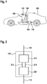
- FIG. 12 shows a flowchart of a method 300 according to one embodiment.
- the method 300 for determining a driver's visual distraction can be performed, for example, using a device as described above with reference to FIG Figures 1 and 2 is described.
- the driver's attention is modeled by forming the attention card.
- the modeling of the need for attention takes place by forming the attention demand map, for example in the form of a coldmap.
- the two maps are compared in step 320 to determine the distraction value representing the driver's visual distraction.
- FIG. 12 shows a flowchart of a method 300 according to one embodiment. Shown is a basic model for the detection of impermissible visual distraction. In this case, in step 310, the detection of a selective visual attention of the driver by modeling the attention card and in step 315, the detection of the attention needs from the environmental condition by modeling the attention needs map. Finally, in step 320, a distraction hypothesis is established by detecting impermissible deflection on the basis of a desired-actual comparison between the two maps.
- Fig. 5 shows a schematic representation of a coordinate system 500 for use in a method according to an embodiment, such as a previously described with reference to FIGS. 1 to 4 described method. Shown is an example of a spherical coordinate system with the polar coordinates polar angle ⁇ and azimuth angle ⁇ for displaying attentional directions.
- So-called heat maps are used to model a state of attention of the driver and the need for attention from the environment.
- spherical coordinates are used to transform directions of attention into a two-dimensional map (polar angle ⁇ and azimuth angle ⁇ ). Accordingly, such a heatmap is completely writable using an n ⁇ m matrix.
- the need for attention is described with a coldmap that depicts a "negative heat”.
- the origin 0 of this heatmap should be at the center of a headbox, that is, in an area where the driver's head is usually located. Errors caused by the driver's head not being in this position can be neglected, since deviations of the head positions are small compared to the longitudinal distance to the viewed objects outside the vehicle. Accordingly, the heat and cold map are used only for objects outside the vehicle.
- these heat and cold maps are spanned on a sphere around the vehicle in order to be able to model the entire environment of the vehicle, for example with a value range for the polar angle ⁇ between minus 180 degrees and plus 180 degrees.
- the range of values for the azimuth angle ⁇ may be smaller, for example, between minus 60 degrees and plus 60 degrees, where 0 degrees corresponds to a horizontal.
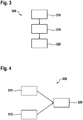
- Fig. 6 shows a schematic representation of a attention card 600 according to an embodiment. Shown is an example of a heatmap as a attention card for the visualization of the attention distribution.
- the vehicle environment is merely exemplified by a rectangle 602 indicated. In this case, for example, map areas with different degrees of accumulation of viewing directions are shown in different colors.
- FIG. 15 is a diagram illustrating an attention density function 700 for use in a method according to an embodiment such as that described above with reference to FIG FIGS. 1 to 6 described method.
- the attention density is shown as a function of an eccentricity angle ⁇ .
- a more detailed description of the attention density function 700 can be found in the following description.
- FIG. 15 is a diagram illustrating a weighting function 800, here an expiration function, for use in a method according to an embodiment, such as that described above with reference to FIG FIGS. 1 to 7 described method.
- the weighting function 800 is dependent on represented a time t and exemplifies a modeled memory of the driver. Furthermore, a standard time window 802, in which the direction of view or head position of the driver is processed by default, for example, with a window size of 5 seconds, located.
- the weighting function 800 is for taking into account a deterioration of looks after a certain time. A corresponding decay factor is described, for example, by a function as a function of the past time.
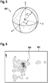
- Fig. 9 shows a schematic representation of a view distribution in a vehicle 100, such as a preceding with reference to Fig. 1 described vehicle.
- the vehicle 100 is shown in plan view, a direction of travel of the vehicle 100 is with a in Fig. 9 marked upwards arrow 902.
- Arrows 906, 908, 910 which are directed opposite to the direction of travel, symbolize in each case lines of sight of the driver when looking through a left exterior mirror 912, a right exterior mirror 914 and an interior mirror 916.
- Areas with more "cold” are areas to which the driver pays too little visual attention. This can also be called a positive attention gap. On the other hand, in areas with more "heat” the driver pays too much attention, also called a negative attention gap, which means distracting the driver.
- a warning function is triggered.
- a warning function is triggered.
- the driver is distracted, but also those areas to which he pays too much attention and those areas to which he pays too little attention.
- HMI functions such as LED treadmills, a direction-dependent display of sounds or vibrations.
- the driver's selective visual attention is detected by describing an accumulation of the viewing directions in a moving window.
- the window size is set to 5 seconds and describes the last 5 seconds.
- Various modular extensions are conceivable, each of which can increase the accuracy of the modeling. These will be described below by way of example.
- the eccentricity angle ⁇ is used concentrically with the driver's foveal axis.
- the attention density ie the "heat" density
- Fig. 8 the attention density function
- the temporal component of human memory is considered.
- glances expire after a certain period of time, for example corresponding to the window size mentioned above after 5 seconds.
- a decay function is introduced, with which past glances are multiplied according to their age.
- the rigid view is first recognized accordingly, for example on the basis of a saccade and fixation frequency.
- the accumulation of the gaze directions becomes the attention card, i. H. to the heatmap, so that no additional "heat” is taken into account for these periods. If this condition is maintained for a longer period of time, this results in an empty heat map - the driver does not pay any attention.
- mirror views into one of the existing exterior mirrors always apply to the vehicle surroundings, but usually to a rear area of the vehicle. Accordingly, according to one exemplary embodiment, mirror views are evaluated as rearward views and considered as such in the calculation of the attention card. For this reason, it is advantageous if the attention card is built around the entire vehicle, and not just around its front part.
- the need for attention from the vehicle environment is modeled depending on the information available about the vehicle environment.
- no information about the vehicle environment is available.
- a standard distribution is used for the attention demand card. This is optionally taking into account mirror and shoulder views of the driver.
- the attention demand card is adjusted according to the requirements as follows.
- a road type such as inner-city road, country road or motorway is available.
- the need for attention changes. For example, in urban areas a much wider distribution of attention is required than on highways.
- This is stored, for example, in standard attention demand cards for the respective environments. For example, the presence of infrastructure elements such as intersections or crosswalks in corresponding coldmaps is taken into account.
- Outdoor camera information can be used to know road characteristics.
- information such as the number of lanes, track position or curvature of the lanes, d. H. the presence of curves, provided. This information is used to adjust the attention card accordingly.
- positions and types of environment objects such as vehicles, pedestrians and other road users are available via corresponding environment model information, these, for example, are also used to adapt the Attention needs used.
- environment model information such as vehicles, pedestrians and other road users
- an evaluation of the criticality of the respective objects is additionally available.
- This information is now used to create additional "cold" at the appropriate places in the coldmap. This should correspond to the position and the criticality of the respective objects. The higher the criticality, the more coldness is generated.
- an exemplary embodiment comprises a "and / or" link between a first feature and a second feature, then this is to be read so that the embodiment according to one embodiment, both the first feature and the second feature and according to another embodiment either only first feature or only the second feature.
Abstract
Die Erfindung betrifft ein Verfahren zum Ermitteln einer visuellen Ablenkung eines Fahrers (106) eines Fahrzeugs (100). Dabei wird zunächst eine Aufmerksamkeit des Fahrers (106) durch Bilden einer Aufmerksamkeitskarte unter Verwendung einer Fahrerinformation (108), die eine mittels eines Sensors (104) des Fahrzeugs (100) erfasste Blickrichtung und/oder Kopfhaltung des Fahrers (106) und/oder eine Orientierung eines Oberkörpers des Fahrers (106) repräsentiert, modelliert. Die Aufmerksamkeitskarte repräsentiert eine von der Blickrichtung und/oder der Kopfhaltung abhängige Ist-Verteilung der Aufmerksamkeit des Fahrers (106) in einem zweidimensionalen Koordinatensystem, wobei das zweidimensionale Koordinatensystem zumindest einen Teilbereich einer Umgebung des Fahrzeugs (100) abbildet. Ferner wird ein Aufmerksamkeitsbedarf durch Bilden einer Aufmerksamkeitsbedarfskarte modelliert, wobei die Aufmerksamkeitsbedarfskarte eine Soll-Verteilung der Aufmerksamkeit des Fahrers (106) in dem zweidimensionalen Koordinatensystem (500) repräsentiert. Schließlich werden die Aufmerksamkeitskarte und die Aufmerksamkeitsbedarfskarte miteinander verglichen, um einen die visuelle Ablenkung des Fahrers (106) repräsentierenden Ablenkungswert (110) zu ermitteln.

Description
Die Erfindung geht aus von einer Vorrichtung oder einem Verfahren nach Gattung der unabhängigen Ansprüche. Gegenstand der vorliegenden Erfindung ist auch ein Computerprogramm.The invention is based on a device or a method according to the preamble of the independent claims. The subject of the present invention is also a computer program.
Es sind Systeme zur Erfassung einer visuellen Ablenkung eines Fahrers bekannt. Die visuelle Ablenkung kann hierbei beispielsweise abhängig von einem Blickwinkel oder einer Kopfpose des Fahrers ermittelt werden.Systems for detecting a driver's visual distraction are known. The visual distraction can be determined, for example, depending on a perspective or a head pose of the driver.
Vor diesem Hintergrund werden mit dem hier vorgestellten Ansatz ein Verfahren zum Ermitteln einer visuellen Ablenkung eines Fahrers eines Fahrzeugs, weiterhin eine Vorrichtung, die dieses Verfahren verwendet, sowie schließlich ein entsprechendes Computerprogramm gemäß den Hauptansprüchen vorgestellt. Durch die in den abhängigen Ansprüchen aufgeführten Maßnahmen sind vorteilhafte Weiterbildungen und Verbesserungen der im unabhängigen Anspruch angegebenen Vorrichtung möglich.Against this background, with the approach presented here, a method for determining a visual distraction of a driver of a vehicle, furthermore a device which uses this method, and finally a corresponding computer program according to the main claims are presented. The measures listed in the dependent claims advantageous refinements and improvements of the independent claim device are possible.
Es wird ein Verfahren zum Ermitteln einer visuellen Ablenkung eines Fahrers eines Fahrzeugs vorgestellt, wobei das Verfahren folgende Schritte umfasst:
- Modellieren einer Aufmerksamkeit des Fahrers durch Bilden einer Aufmerksamkeitskarte unter Verwendung einer Fahrerinformation, die eine mittels eines Sensors des Fahrzeugs erfasste Blickrichtung und/oder Kopfhaltung des Fahrers und/oder eine Orientierung eines Oberkörpers des Fahrers repräsentiert, wobei die Aufmerksamkeitskarte eine von der Blickrichtung und/oder der Kopfhaltung abhängige Ist-Verteilung der Aufmerksamkeit des Fahrers in einem zweidimensionalen Koordinatensystem repräsentiert, wobei das zweidimensionale Koordinatensystem zumindest einen Teilbereich einer Umgebung des Fahrzeugs abbildet;
- Modellieren eines Aufmerksamkeitsbedarfs durch Bilden einer Aufmerksamkeitsbedarfskarte, wobei die Aufmerksamkeitsbedarfskarte eine Soll-Verteilung der Aufmerksamkeit des Fahrers in dem zweidimensionalen Koordinatensystem repräsentiert; und
- Vergleichen der Aufmerksamkeitskarte mit der Aufmerksamkeitsbedarfskarte, um einen die visuelle Ablenkung des Fahrers repräsentierenden Ablenkungswert zu ermitteln.
- Modeling a driver's attention by forming an attention card using driver information that includes a represents the direction of view and / or head posture of the driver detected by a sensor of the vehicle and / or an orientation of a driver's upper body, wherein the attention card represents an actual distribution of the driver's attention in a two-dimensional coordinate system dependent on the viewing direction and / or head posture; wherein the two-dimensional coordinate system maps at least a portion of an environment of the vehicle;
- Modeling an attention demand by forming an attention demand map, the attention demand map representing a target distribution of the driver's attention in the two-dimensional coordinate system; and
- Comparing the attention card to the attention demand map to determine a distraction value representative of the driver's visual distraction.
Unter einer visuellen Ablenkung kann eine Ablenkung des Fahrers durch bestimmte Objekte oder Ereignisse in einer Umgebung des Fahrzeugs verstanden werden, durch die beim Fahrer ein Aufmerksamkeitsdefizit entsteht. Unter einer Aufmerksamkeitskarte kann eine sogenannte Heatmap als Visualisierungstechnik für einen Ort der häufigsten Blickposition (d. h. diejenigen Positionen, an denen der Blick oft verweilt, werden als "heiß" bezeichnet) verstanden werden, durch die Richtungen der Aufmerksamkeit des Fahrers in eine zweidimensionale Abbildung transformierbar sind, beispielsweise in ein Kugelkoordinatensystem mit den Koordinaten Polarwinkel und Azimutwinkel. Die Aufmerksamkeitskarte kann beispielsweise mittels einer m×n-Matrix beschreibbar sein. Ebenso kann auch unter einer Aufmerksamkeitsbedarfskarte analog zur Aufmerksamkeitskarte eine zweidimensionale Abbildung eines Aufmerksamkeitsbedarfs bezüglich der Umgebung des Fahrzeugs in dem Koordinatensystem verstanden werden. Beispielsweise kann die Aufmerksamkeitsbedarfskarte als eine Art Negativ zur Aufmerksamkeitskarte ausgebildet sein. Unter einer Aufmerksamkeitsbedarfskarte kann in diesem Sinne auch eine Coldmap zur Darstellung einer "negativen Hitze" (Kälte) verstanden werden.A visual distraction can be understood as a distraction of the driver by certain objects or events in an environment of the vehicle, which causes an attention deficit for the driver. Under an attention card, a so-called heat map can be understood as a visualization technique for a location of most common viewing position (ie, those positions in which the gaze often lingers are termed "hot") by which directions of the driver's attention are transformable into a two-dimensional image , For example, in a spherical coordinate system with the coordinates polar angle and azimuth angle. The attention card can be described, for example, by means of an m × n matrix. Likewise, an attention demand card analogous to the attention card can be understood to be a two-dimensional illustration of a need for attention with regard to the surroundings of the vehicle in the coordinate system. For example, the attention demand card may be formed as a kind of negative to the attention card. In this sense, an attention demand card can also be understood as a coldmap for representing a "negative heat" (cold).
Bei dem Sensor des Fahrzeugs kann es sich beispielsweise um einen Innenraumsensor des Fahrzeugs, etwa eine (Infrarot-) Kamera oder Ähnliches, handeln.The sensor of the vehicle may be, for example, an interior sensor of the vehicle, such as an (infrared) camera or the like.
Der Ablenkungswert kann beispielsweise eine Differenz zwischen der Aufmerksamkeitskarte und der Aufmerksamkeitsbedarfskarte repräsentieren.For example, the distraction value may represent a difference between the attention card and the attention demand card.
Der hier vorgestellte Ansatz beruht auf der Erkenntnis, dass eine unzulässige visuelle Ablenkung eines Fahrers eines Fahrzeugs, d. h. ein Aufmerksamkeitsdefizit, unter Verwendung von Heatmaps zur Modellierung eines Aufmerksamkeitszustands des Fahrers und eines Aufmerksamkeitsbedarfs detektiert werden kann. Ein solches Verfahren bietet je nach Ausführungsform folgende Vorteile.The approach presented here is based on the recognition that an inadmissible visual distraction of a driver of a vehicle, i. H. an attention deficit can be detected using heat maps to model a driver's attentiveness and attention needs. Such a method offers the following advantages depending on the embodiment.
Der Aufmerksamkeitsbedarf kann an tatsächliche Umgebungsbedingungen adaptiert werden.The attention needs can be adapted to actual environmental conditions.
Es ist möglich, eine Richtung, in der mehr Aufmerksamkeit erforderlich ist, zu bestimmen, statt lediglich zu bestimmen, ob grundsätzlich ungenügende Aufmerksamkeit vorliegt.It is possible to determine a direction in which more attention is needed, rather than simply determining whether there is generally insufficient attention.
Es kann die periphere Wahrnehmung des Fahrers bei der Modellierung mit einbezogen werden.The peripheral perception of the driver can be included in the modeling.
Ferner kann beispielsweise das Wissen des Fahrers über Umgebungsobjekte in der Modellierung abgebildet werden. Dies ist insbesondere bei Zustandsänderungen relevant, etwa wenn ein voranfahrendes Fahrzeug abbremst.Furthermore, for example, the knowledge of the driver about environment objects in the modeling can be mapped. This is particularly relevant in the case of changes of state, for example when a preceding vehicle decelerates.
Ein weiterer Vorteil besteht in der Möglichkeit, die zeitliche Dynamik des Vergessens visueller Eindrücke, etwa wenn der Fahrer die Blickrichtung wechselt, detailliert zu modellieren.Another advantage is the ability to model in detail the temporal dynamics of forgetting visual impressions, such as when the driver changes his direction of view.
Der hier vorgestellte Ansatz gewährleistet somit eine sehr hohe Modularität und Variabilität.The approach presented here thus ensures a very high degree of modularity and variability.
Gemäß einer Ausführungsform kann im Schritt des Modellierens die Aufmerksamkeitskarte oder, zusätzlich oder alternativ, die Aufmerksamkeitsbedarfskarte auf der Basis eines Kugelkoordinatensystems gebildet werden. Dadurch wird eine sphärische und somit möglichst realitätsnahe Abbildung der Fahrzeugumgebung ermöglicht.According to one embodiment, in the modeling step, the attention card or, additionally or alternatively, the attention demand card may be formed based on a spherical coordinate system. This allows a spherical and thus realistic as possible imaging of the vehicle environment.
Von Vorteil ist auch, wenn im Schritt des Modellierens das Kugelkoordinatensystem einen Polarwinkelbereich zwischen minus 180 Grad und plus 180 Grad oder, zusätzlich oder alternativ, einen Azimutwinkelbereich zwischen minus 60 Grad und plus 60 Grad aufweist. Dadurch wird eine effiziente Nachbildung der Umgebung des Fahrzeugs mittels des Koordinatensystems ermöglicht.It is also advantageous if, in the modeling step, the spherical coordinate system has a polar angle range between minus 180 degrees and plus 180 degrees or, additionally or alternatively, an azimuth angle range between minus 60 degrees and plus 60 degrees. This allows an efficient simulation of the environment of the vehicle by means of the coordinate system.
Ferner ist es vorteilhaft, wenn im Schritt des Modellierens die Aufmerksamkeitskarte oder, zusätzlich oder alternativ, die Aufmerksamkeitsbedarfskarte mit einem Koordinatenursprung gebildet wird, der einen Mittelpunkt eines Aufenthaltsbereiches eines Kopfes des Fahrers im Fahrzeug repräsentiert. Dadurch kann der Einfluss longitudinaler Abweichungen der Kopfposition des Fahrers beim Ermitteln der visuellen Ablenkung minimiert werden.Furthermore, it is advantageous if, in the modeling step, the attention card or, additionally or alternatively, the attention demand map is formed with a co-ordinate origin representing a center of a location area of a head of the driver in the vehicle. Thereby, the influence of longitudinal deviations of the head position of the driver when determining the visual distraction can be minimized.
Gemäß einer weiteren Ausführungsform kann im Schritt des Vergleichens eine Differenz aus der Aufmerksamkeitskarte und der Aufmerksamkeitsbedarfskarte gebildet werden, um einen eine positive oder negative Abweichung der Ist-Verteilung von der Soll-Verteilung repräsentierenden Wert als den Ablenkungswert zu ermitteln. Der Ablenkungswert entspricht dabei beispielsweise einer Differenz zwischen dem Ist- und dem Sollwert bzw. einer Ist-Verteilung und einer Soll-Verteilung. Dadurch wird eine differenzierte Detektion der Aufmerksamkeitsverteilung in der Umgebung des Fahrzeugs ermöglicht.According to another embodiment, in the step of comparing, a difference may be formed from the attention card and the attention demand map to determine a value representing a positive or negative deviation of the actual distribution from the target distribution as the deflection value. The deflection value corresponds to, for example, a difference between the actual and the desired value or an actual distribution and a desired distribution. This allows a differentiated detection of the attention distribution in the environment of the vehicle.
Gemäß einer weiteren Ausführungsform kann im Schritt des Modellierens unter Verwendung der Fahrerinformation ein zu einer fovealen Sehachse des Fahrers konzentrischer Exzentrizitätswinkel ermittelt und verwendet werden, um eine periphere Wahrnehmung des Fahrers zu modellieren. Diese Modellierung kann beispielsweise durch unterschiedliche Gewichtung der angenommenen Aufmerksamkeit in zentralen und peripheren Sichtbereichen erfolgen. Entsprechend kann die Aufmerksamkeitskarte unter Berücksichtigung der modellierten peripheren Wahrnehmung gebildet werden. Unter einer fovealen Sehachse kann beispielsweise eine gedachte gerade Linie, die vom Mittelpunkt der Fovea centralis (Netzhaut) durch den Mittelpunkt der Pupille verläuft, verstanden werden. Dadurch kann die visuelle Ablenkung des Fahrers unter Berücksichtigung der peripheren Wahrnehmung des Fahrers ermittelt werden. Somit kann die Zuverlässigkeit des Verfahrens deutlich erhöht werden.According to another embodiment, in the step of modeling using the driver information, a to a foveal visual axis of the driver Concentric eccentricity can be determined and used to model a peripheral perception of the driver. This modeling can be done, for example, by varying the weighting of perceived attention in central and peripheral viewing areas. Accordingly, the attention card can be formed taking into account the modeled peripheral perception. By way of example, a foveal visual axis can be understood to mean an imaginary straight line that runs from the center of the fovea centralis (retina) through the center of the pupil. Thereby, the visual distraction of the driver can be determined taking into account the peripheral perception of the driver. Thus, the reliability of the process can be significantly increased.
Es ist vorteilhaft, wenn im Schritt des Modellierens die Fahrerinformation unter Verwendung einer Gewichtungsfunktion zeitabhängig gewichtet wird. Dabei kann die Aufmerksamkeitskarte unter Verwendung der gewichteten Fahrerinformation gebildet werden. Unter einer Gewichtungsfunktion kann beispielsweise eine Verfallsfunktion verstanden werden, mit der eine Blickrichtung oder Kopfhaltung des Fahrers entsprechend ihres Alters multipliziert werden kann. Dadurch kann ein dem menschlichen Erinnerungsvermögen entsprechendes zeitliches Verblassen eines visuellen Eindrucks, der einer bestimmten Blickrichtung oder Kopfhaltung des Fahrers entsprechen kann, beim Ermitteln der visuellen Ablenkung berücksichtigt werden.It is advantageous if, in the modeling step, the driver information is weighted using a weighting function in a time-dependent manner. The attention card can be formed using the weighted driver information. By a weighting function, for example, a decay function can be understood with which a line of sight or head posture of the driver can be multiplied according to their age. Thereby, a temporal fading of a visual impression corresponding to the human memory, which may correspond to a particular line of vision or head posture of the driver, may be taken into account in determining the visual distraction.
Ferner kann im Schritt des Modellierens die Fahrerinformation verwendet werden, um einen starren Blick des Fahrers zu erkennen. Dabei kann die Aufmerksamkeitskarte abhängig von einer Erkennung des starren Blicks des Fahrers gebildet werden. Unter einem starren Blick kann ein Blick mit geringem Informationsgehalt oder fehlender Informationsaufnahme verstanden werden. Durch diese Ausführungsform kann die Zuverlässigkeit des Verfahrens weiter erhöht werden.Further, in the step of modeling, the driver information may be used to detect a rigid gaze of the driver. In this case, the attention card can be formed depending on a recognition of the driver's rigid gaze. Under a fixed gaze, a look with little information content or lack of information can be understood. By this embodiment, the reliability of the method can be further increased.
Des Weiteren kann im Schritt des Modellierens unter Verwendung der Fahrerinformation ein Spiegelblick oder, zusätzlich oder alternativ, ein Schulterblick des Fahrers ermittelt werden. Dabei kann die Aufmerksamkeitskarte dementsprechend unter Berücksichtigung des Spiegelblicks oder des Schulterblicks oder beider Blickarten gebildet werden. Durch diese Ausführungsform wird eine besonders genaue Detektion der visuellen Ablenkung ermöglicht.Furthermore, in the step of modeling using the driver information, a mirror view or, in addition or alternatively, a shoulder view of the driver can be determined. The attention card can accordingly, taking into account the Mirror look or shoulder look or both look styles. This embodiment enables a particularly accurate detection of the visual distraction.
Gemäß einer weiteren Ausführungsform kann im Schritt des Modellierens die Aufmerksamkeitsbedarfskarte unter Verwendung einer von einem Umfeldsensor des Fahrzeugs bereitgestellten Umfeldinformation oder, zusätzlich oder alternativ, einer Navigationsinformation zum Navigieren des Fahrzeugs anhand einer digitalen Karte gebildet werden. Dadurch kann die visuelle Ablenkung situationsabhängig mit hoher Genauigkeit ermittelt werden.According to a further embodiment, in the modeling step, the attention demand map may be formed using environment information provided by an environment sensor of the vehicle or, additionally or alternatively, navigation information for navigating the vehicle from a digital map. As a result, the visual deflection can be determined depending on the situation with high accuracy.
Dabei kann im Schritt des Modellierens die Umfeldinformation zusätzlich oder alternativ, die Navigationsinformation einen Straßentyp, eine Fahrspuranzahl, eine Fahrspurposition, eine Fahrspurkrümmung oder eine Objektinformation bezüglich zumindest eines Objekts in der Umgebung des Fahrzeugs oder eine Kombination aus zumindest zwei der genannten Parameter repräsentieren. Die Objektinformation kann beispielsweise eine Position, eine Art oder eine Zustandsänderung des Objekts repräsentieren. Dadurch wird eine besonders genaue situationsabhängige Modellierung der visuellen Ablenkung ermöglicht.In this case, in the modeling step, additionally or alternatively, the navigation information may represent a road type, a lane number, a lane position, a lane curvature or object information relating to at least one object in the surroundings of the vehicle or a combination of at least two of said parameters. The object information may represent, for example, a position, a type or a state change of the object. This allows a particularly accurate situation-dependent modeling of the visual distraction.
Dieses Verfahren kann beispielsweise in Software oder Hardware oder in einer Mischform aus Software und Hardware, beispielsweise in einem Steuergerät, implementiert sein.This method can be implemented, for example, in software or hardware or in a mixed form of software and hardware, for example in a control unit.
Der hier vorgestellte Ansatz schafft ferner eine Vorrichtung, die ausgebildet ist, um die Schritte einer Variante eines hier vorgestellten Verfahrens in entsprechenden Einrichtungen durchzuführen, anzusteuern bzw. umzusetzen. Auch durch diese Ausführungsvariante der Erfindung in Form einer Vorrichtung kann die der Erfindung zugrunde liegende Aufgabe schnell und effizient gelöst werden.The approach presented here also creates a device that is designed to perform the steps of a variant of a method presented here in appropriate facilities to drive or implement. Also by this embodiment of the invention in the form of a device, the object underlying the invention can be solved quickly and efficiently.
Hierzu kann die Vorrichtung zumindest eine Recheneinheit zum Verarbeiten von Signalen oder Daten, zumindest eine Speichereinheit zum Speichern von Signalen oder Daten, zumindest eine Schnittstelle zu einem Sensor oder einem Aktor zum Einlesen von Sensorsignalen von dem Sensor oder zum Ausgeben von Daten- oder Steuersignalen an den Aktor und/oder zumindest eine Kommunikationsschnittstelle zum Einlesen oder Ausgeben von Daten aufweisen, die in ein Kommunikationsprotokoll eingebettet sind. Die Recheneinheit kann beispielsweise ein Signalprozessor, ein Mikrocontroller oder dergleichen sein, wobei die Speichereinheit ein Flash-Speicher, ein EPROM oder eine magnetische Speichereinheit sein kann. Die Kommunikationsschnittstelle kann ausgebildet sein, um Daten drahtlos und/oder leitungsgebunden einzulesen oder auszugeben, wobei eine Kommunikationsschnittstelle, die leitungsgebundene Daten einlesen oder ausgeben kann, diese Daten beispielsweise elektrisch oder optisch aus einer entsprechenden Datenübertragungsleitung einlesen oder in eine entsprechende Datenübertragungsleitung ausgeben kann.For this purpose, the device may comprise at least one computing unit for processing signals or data, at least one memory unit for storing signals or data, at least one interface to a sensor or an actuator for reading sensor signals from the sensor or for outputting of data or control signals to the actuator and / or at least one communication interface for reading in or outputting data embedded in a communication protocol. The arithmetic unit may be, for example, a signal processor, a microcontroller or the like, wherein the memory unit may be a flash memory, an EPROM or a magnetic memory unit. The communication interface can be designed to read or output data wirelessly and / or by line, wherein a communication interface that can read or output line-bound data, for example, electrically or optically read this data from a corresponding data transmission line or output to a corresponding data transmission line.
Unter einer Vorrichtung kann vorliegend ein elektrisches Gerät verstanden werden, das Sensorsignale verarbeitet und in Abhängigkeit davon Steuer- und/oder Datensignale ausgibt. Die Vorrichtung kann eine Schnittstelle aufweisen, die hard- und/oder softwaremäßig ausgebildet sein kann. Bei einer hardwaremäßigen Ausbildung können die Schnittstellen beispielsweise Teil eines sogenannten System-ASICs sein, der verschiedenste Funktionen der Vorrichtung beinhaltet. Es ist jedoch auch möglich, dass die Schnittstellen eigene, integrierte Schaltkreise sind oder zumindest teilweise aus diskreten Bauelementen bestehen. Bei einer softwaremäßigen Ausbildung können die Schnittstellen Softwaremodule sein, die beispielsweise auf einem Mikrocontroller neben anderen Softwaremodulen vorhanden sind.In the present case, a device can be understood as meaning an electrical device which processes sensor signals and outputs control and / or data signals in dependence thereon. The device may have an interface, which may be formed in hardware and / or software. In the case of a hardware-based embodiment, the interfaces can be part of a so-called system ASIC, for example, which contains a wide variety of functions of the device. However, it is also possible that the interfaces are their own integrated circuits or at least partially consist of discrete components. In a software training, the interfaces may be software modules that are present, for example, on a microcontroller in addition to other software modules.
In einer vorteilhaften Ausgestaltung erfolgt durch die Vorrichtung eine Steuerung des Fahrzeugs. Hierzu kann die Vorrichtung beispielsweise auf Sensorsignale wie Beschleunigungs-, Druck-, Lenkwinkel- oder Umfeldsensorsignale zugreifen. Die Ansteuerung erfolgt über Aktoren wie Brems- oder Lenkaktoren oder ein Motorsteuergerät des Fahrzeugs.In an advantageous embodiment, the device is used to control the vehicle. For this purpose, the device can access, for example, sensor signals such as acceleration, pressure, steering angle or environmental sensor signals. The control takes place via actuators such as brake or steering actuators or an engine control unit of the vehicle.
Von Vorteil ist auch ein Computerprogrammprodukt oder Computerprogramm mit Programmcode, der auf einem maschinenlesbaren Träger oder Speichermedium wie einem Halbleiterspeicher, einem Festplattenspeicher oder einem optischen Speicher gespeichert sein kann und zur Durchführung, Umsetzung und/oder Ansteuerung der Schritte des Verfahrens nach einer der vorstehend beschriebenen Ausführungsformen verwendet wird, insbesondere wenn das Programmprodukt oder Programm auf einem Computer oder einer Vorrichtung ausgeführt wird.Also of advantage is a computer program product or computer program with program code which can be stored on a machine-readable carrier or storage medium such as a semiconductor memory, a hard disk memory or an optical memory and for carrying out, implementing and / or controlling the steps of the method according to one of the above described embodiments, in particular when the program product or program is executed on a computer or a device.
Ausführungsbeispiele der Erfindung sind in den Zeichnungen dargestellt und in der nachfolgenden Beschreibung näher erläutert. Es zeigt:
-
Fig. 1 eine schematische Darstellung eines Fahrzeugs mit einer Vorrichtung gemäß einem Ausführungsbeispiel; -
Fig. 2 eine schematische Darstellung einer Vorrichtung gemäß einem Ausführungsbeispiel; -
Fig. 3 ein Ablaufdiagramm eines Verfahrens gemäß einem Ausführungsbeispiel; -
Fig. 4 ein Ablaufdiagramm eines Verfahrens gemäß einem Ausführungsbeispiel; -
Fig. 5 eine schematische Darstellung eines Koordinatensystems zur Verwendung in einem Verfahren gemäß einem Ausführungsbeispiel; -
Fig. 6 eine schematische Darstellung einer Aufmerksamkeitskarte gemäß einem Ausführungsbeispiel; -
Fig. 7 ein Diagramm zur Darstellung einer Aufmerksamkeitsdichtefunktion zur Verwendung in einem Verfahren gemäß einem Ausführungsbeispiel; -
Fig. 8 ein Diagramm zur Darstellung einer Gewichtungsfunktion zur Verwendung in einem Verfahren gemäß einem Ausführungsbeispiel; und -
Fig. 9 eine schematische Darstellung einer Blickverteilung in einem Fahrzeug.
-
Fig. 1 a schematic representation of a vehicle with a device according to an embodiment; -
Fig. 2 a schematic representation of a device according to an embodiment; -
Fig. 3 a flowchart of a method according to an embodiment; -
Fig. 4 a flowchart of a method according to an embodiment; -
Fig. 5 a schematic representation of a coordinate system for use in a method according to an embodiment; -
Fig. 6 a schematic representation of a attention card according to an embodiment; -
Fig. 7 a diagram illustrating an attention density function for use in a method according to an embodiment; -
Fig. 8 a diagram illustrating a weighting function for use in a method according to an embodiment; and -
Fig. 9 a schematic representation of a view distribution in a vehicle.
In der nachfolgenden Beschreibung günstiger Ausführungsbeispiele der vorliegenden Erfindung werden für die in den verschiedenen Figuren dargestellten und ähnlich wirkenden Elemente gleiche oder ähnliche Bezugszeichen verwendet, wobei auf eine wiederholte Beschreibung dieser Elemente verzichtet wird.In the following description of favorable embodiments of the present invention are for the in the various figures illustrated and similar elements used the same or similar reference numerals, wherein a repeated description of these elements is omitted.
Die Vorrichtung 102 ist ferner ausgebildet, um Bereiche der Fahrzeugumgebung, die einer erhöhten Aufmerksamkeit des Fahrers bedürfen, in einer entsprechenden Aufmerksamkeitsbedarfskarte analog zur Aufmerksamkeitskarte unter Verwendung des zweidimensionalen Koordinatensystems zu modellieren. Optional erfolgt die Modellierung der Aufmerksamkeitsbedarfskarte ebenfalls unter Verwendung der Fahrerinformation 108, d. h. abhängig von einer jeweiligen Blickrichtung oder Kopfhaltung des Fahrers 106 bezüglich der Fahrzeugumgebung. Die Aufmerksamkeitsbedarfskarte repräsentiert somit im Gegensatz zur Aufmerksamkeitskarte eine Soll-Verteilung der Aufmerksamkeit des Fahrers 106.The
Um die visuelle Ablenkung des Fahrers 106 zu ermitteln, führt die Vorrichtung 102 einen Vergleich zwischen den beiden Karten durch, etwa mittelsTo determine the visual distraction of the
Differenzbildung. Als Ergebnis dieses Vergleichs gibt die Vorrichtung 102 einen die visuelle Ablenkung repräsentierenden Ablenkungswert 110 aus. Dieser wird beispielsweise von einem Steuergerät des Fahrzeugs 100 verwendet, um in Abhängigkeit von der visuellen Ablenkung einen Warnhinweis zum Warnen des Fahrers 106 oder, etwa im Kontext einer teil- oder hochautomatisierten Steuerung des Fahrzeugs 100, ein Ansteuersignal zum Ansteuern zumindest eines Aktors des Fahrzeugs 100, etwa eines Lenk- oder Bremsaktors, zu generieren.Difference. As a result of this comparison, the
Zur Detektion einer unzulänglichen visuellen Ablenkung des Fahrers 106 wird ein Soll-Ist-Vergleich einer selektiven (gerichteten) Fahreraufmerksamkeit mit dem sich ergebenden Aufmerksamkeitsbedarf aus der Fahrzeugumgebung durchgeführt. Dazu werden grundsätzlich die folgenden drei Schritte unter Verwendung der Vorrichtung 102 durchgeführt:
- 1. Detektion des selektiven visuellen Aufmerksamkeitszustandes des Fahrers;
- 2. Detektion des Aufmerksamkeitsbedarfs aus der Fahrzeugumgebung; und
- 3. Detektion von unzulässiger Ablenkung mithilfe eines Soll-Ist-Vergleiches.
- 1. Detection of the driver's selective visual attention condition;
- 2. Detection of attention needs from the vehicle environment; and
- 3. Detection of impermissible deflection by means of a target-actual comparison.
Zur Modellierung eines Aufmerksamkeitszustandes des Fahrers sowie des Aufmerksamkeitsbedarfs aus der Umgebung werden sogenannte Heatmaps verwendet. Dabei werden beispielsweise Kugelkoordinaten verwendet, um Richtungen der Aufmerksamkeit in eine zweidimensionale Abbildung zu transformieren (Polarwinkel ϕ und Azimutwinkel θ). Entsprechend ist eine derartige Heatmap mithilfe einer n×m-Matrix vollständig beschreibbar. Analog dazu wird der Aufmerksamkeitsbedarf mit einer Coldmap, die eine "negative Hitze" abbildet, beschrieben.So-called heat maps are used to model a state of attention of the driver and the need for attention from the environment. For example, spherical coordinates are used to transform directions of attention into a two-dimensional map (polar angle φ and azimuth angle θ). Accordingly, such a heatmap is completely writable using an n × m matrix. Similarly, the need for attention is described with a coldmap that depicts a "negative heat".
Der Ursprung 0 dieser Heatmap sollte im Mittelpunkt einer Headbox liegen, also in einem Bereich, in dem sich der Kopf des Fahrers üblicherweise aufhält. Fehler, die dadurch entstehen, dass sich der Kopf des Fahrers nicht an dieser Stelle aufhält, können vernachlässigt werden, da die Abweichungen der Kopfpositionen im Vergleich zum longitudinalen Abstand zu den angeschauten Objekten außerhalb des Fahrzeugs gering sind. Entsprechend werden die Heat- und Coldmap nur für Objekte außerhalb des Fahrzeugs verwendet.The origin 0 of this heatmap should be at the center of a headbox, that is, in an area where the driver's head is usually located. Errors caused by the driver's head not being in this position can be neglected, since deviations of the head positions are small compared to the longitudinal distance to the viewed objects outside the vehicle. Accordingly, the heat and cold map are used only for objects outside the vehicle.
Gemäß einem Ausführungsbeispiel werden diese Heat- und Coldmaps auf einer Sphäre rund um das Fahrzeug aufgespannt, um das gesamte Umfeld des Fahrzeugs modellieren zu können, etwa mit einem Wertebereich für den Polarwinkel ϕ zwischen minus 180 Grad und plus 180 Grad. Der Wertebereich für den Azimutwinkel θ kann geringer ausfallen und liegt beispielsweise zwischen minus 60 Grad und plus 60 Grad, wobei 0 Grad einer Waagerechten entspricht.According to one embodiment, these heat and cold maps are spanned on a sphere around the vehicle in order to be able to model the entire environment of the vehicle, for example with a value range for the polar angle φ between minus 180 degrees and plus 180 degrees. The range of values for the azimuth angle θ may be smaller, for example, between minus 60 degrees and plus 60 degrees, where 0 degrees corresponds to a horizontal.
Nachfolgend wird der hier vorgestellte Ansatz nochmals modular beschrieben.The approach presented here will be described again modularly.
Um im Rahmen der Ablenkungshypothese eine unzulässig hohe Ablenkung zu detektieren, wird beispielsweise lediglich eine Differenz beider Maps - Heatmap und Coldmap - gebildet: ![]()
![]()
![]()
![]()
Bereiche mit mehr "Kälte" sind Bereiche, denen der Fahrer zu wenig visuelle Aufmerksamkeit schenkt. Dies kann auch als positive Aufmerksamkeitslücke bezeichnet werden. Bereichen mit mehr "Wärme" schenkt der Fahrer hingegen zu viel Aufmerksamkeit, auch negative Aufmerksamkeitslücke genannt, was eine Ablenkung des Fahrers bedeutet.Areas with more "cold" are areas to which the driver pays too little visual attention. This can also be called a positive attention gap. On the other hand, in areas with more "heat" the driver pays too much attention, also called a negative attention gap, which means distracting the driver.
Im Rahmen einer Grenzwertüberschreitung wird beispielsweise eine Warnfunktion angetriggert. Dabei ist im Gegensatz zum Stand der Technik nicht nur die Tatsache bekannt, dass der Fahrer abgelenkt ist, sondern es sind zudem diejenigen Bereiche, denen er zu viel Aufmerksamkeit schenkt, und diejenigen Bereiche, denen er zu wenig Aufmerksamkeit schenkt, bekannt. Dies hat den Vorteil, dass die visuelle Aufmerksamkeit des Fahrers durch geeignete HMI-Funktionen wie etwa LED-Laufbänder, eine richtungsabhängige Darstellung von Tönen oder Vibrationen in die der aktuellen Situation entsprechende Richtung geleitet werden kann.Within the scope of a limit value overrun, for example, a warning function is triggered. In contrast to the prior art, not only is the fact known that the driver is distracted, but also those areas to which he pays too much attention and those areas to which he pays too little attention. This has the advantage that the driver's visual attention can be directed in the direction corresponding to the current situation by means of suitable HMI functions, such as LED treadmills, a direction-dependent display of sounds or vibrations.
Die Detektion der selektiven visuellen Aufmerksamkeit des Fahrers erfolgt im einfachsten Fall durch Beschreibung einer Akkumulation der Blickrichtungen in einem sich bewegenden Fenster. Die Fenstergröße wird dabei beispielsweise auf 5 Sekunden gesetzt und beschreibt jeweils die vergangenen 5 Sekunden. Es sind verschiedene modulare Erweiterungen denkbar, die jeweils die Genauigkeit der Modellierung erhöhen können. Diese werden im Folgenden beispielhaft beschrieben.In the simplest case, the driver's selective visual attention is detected by describing an accumulation of the viewing directions in a moving window. For example, the window size is set to 5 seconds and describes the last 5 seconds. Various modular extensions are conceivable, each of which can increase the accuracy of the modeling. These will be described below by way of example.
Zur Modellierung einer peripheren Wahrnehmung wird der Exzentrizitätswinkel β konzentrisch zur fovealen Achse des Fahrers verwendet. Je größer β ist, desto geringer ist das Wahrnehmungsvermögen des Fahrers an dieser Stelle. Mit einer entsprechenden Funktion wird also die die Aufmerksamkeitsdichte, d. h. die "Hitze"-Dichte, konzentrisch um die foveale Blickrichtung des Fahrers modelliert. Entsprechend dieser Aufmerksamkeitsdichtefunktion, wie sie in
Zur Modellierung eines Erinnerungsvermögens wird die zeitliche Komponente des menschlichen Erinnerns betrachtet. In einer Standardvariante einer Fensterfunktion verfallen Blicke nach einem gewissen Zeitraum, beispielsweise entsprechend der weiter oben genannten Fenstergröße nach 5 Sekunden. Um nun das zeitliche Erinnern besser modellieren zu können, wird eine Verfallsfunktion eingeführt, mit der vergangene Blicke entsprechend ihres Alters multipliziert werden.To model a memory, the temporal component of human memory is considered. In a standard variant of a window function, glances expire after a certain period of time, for example corresponding to the window size mentioned above after 5 seconds. In order to be able to better model temporal memory, a decay function is introduced, with which past glances are multiplied according to their age.
Um starren Blick, d. h. Blicke mit fehlender Informationsaufnahme, in der Modellierung zu berücksichtigen, wird der starre Blick zunächst entsprechend erkannt, etwa anhand einer Sakkaden- und Fixationsfrequenz. Sobald ein starrer Blick des Fahrers erkannt wird, wird die Akkumulation der Blickrichtungen zur Aufmerksamkeitskarte, d. h. zur Heatmap, gestoppt, sodass für diese Zeiträume keine zusätzliche "Hitze" berücksichtigt wird. Wird dieser Zustand für einen längeren Zeitraum aufrechterhalten, so resultiert dies demzufolge in einer leeren Heatmap - der Fahrer zeigt keinerlei Aufmerksamkeit.To stare, d. H. Views with missing information recording, to be considered in the modeling, the rigid view is first recognized accordingly, for example on the basis of a saccade and fixation frequency. As soon as a rigid gaze of the driver is recognized, the accumulation of the gaze directions becomes the attention card, i. H. to the heatmap, so that no additional "heat" is taken into account for these periods. If this condition is maintained for a longer period of time, this results in an empty heat map - the driver does not pay any attention.
Spiegelblicke in einen der vorhandenen Außenspiegel gelten stets der Fahrzeugumgebung, jedoch üblicherweise eines hinteren Bereich des Fahrzeugs. Entsprechend werden Spiegelblicke gemäß einem Ausführungsbeispiel als Blicke nach hinten gewertet und bei der Berechnung der Aufmerksamkeitskarte als solche berücksichtigt. Aus diesem Grund ist es vorteilhaft, wenn die Aufmerksamkeitskarte um das gesamte Fahrzeug, und nicht nur um dessen vorderen Teil, aufgebaut wird.Mirror views into one of the existing exterior mirrors always apply to the vehicle surroundings, but usually to a rear area of the vehicle. Accordingly, according to one exemplary embodiment, mirror views are evaluated as rearward views and considered as such in the calculation of the attention card. For this reason, it is advantageous if the attention card is built around the entire vehicle, and not just around its front part.
Infolge der möglichen Krümmung der Spiegel ist eine angepasste Modellierung des peripheren Sehens bei erkannten Spiegelblicken erforderlich. Insbesondere da die Spiegelorientierung nicht immer bekannt ist, etwa beim Innenspiegel, sollten jeweils Standardverteilungen verwendet werden. Diese sind abhängig davon, in welchen Spiegel geschaut wurde.Due to the possible curvature of the mirrors, an adapted modeling of the peripheral vision is required for detected mirror views. In particular, since the mirror orientation is not always known, for example in the case of the interior mirror, standard distributions should be used in each case. These depend on which mirror was looked at.
Bei erkannten Schulterblicken ist die eigentliche Blickrichtung aufgrund von Sensordefiziten nicht immer bekannt. In diesem Fall wird stattdessen beispielsweise eine angepasste Aufmerksamkeitsverteilung in Abhängigkeit von einer erkannten Kopfrotation des Fahrers verwendet. Es können auch Standardverteilungen zum Einsatz kommen.When shoulder glances are recognized, the actual viewing direction is not always known due to sensor deficits. In this case, for example, an adapted attention distribution is used instead as a function of a recognized head rotation of the driver. Standard distributions can also be used.
Der Aufmerksamkeitsbedarf aus der Fahrzeugumgebung wird abhängig von der zur Verfügung stehenden Information über die Fahrzeugumgebung modelliert. Im einfachsten Fall ist keine Information über die Fahrzeugumgebung verfügbar. In diesem Fall wird beispielsweise eine Standardverteilung für die Aufmerksamkeitsbedarfskarte verwendet. Dies erfolgt optional unter Berücksichtigung von Spiegel- und Schulterblicken des Fahrers.The need for attention from the vehicle environment is modeled depending on the information available about the vehicle environment. In the simplest case, no information about the vehicle environment is available. In this case, for example, a standard distribution is used for the attention demand card. This is optionally taking into account mirror and shoulder views of the driver.
Je nach verfügbarer Information über die Fahrzeugumgebung wird die Aufmerksamkeitsbedarfskarte entsprechend den Anforderungen wie folgt angepasst.Depending on the available information about the vehicle environment, the attention demand card is adjusted according to the requirements as follows.
Über eine entsprechende Navigationsinformation ist beispielsweise ein Straßentyp wie innerörtliche Straße, Landstraße oder Autobahn verfügbar. Je nach erkanntem Straßentyp verändert sich der Aufmerksamkeitsbedarf. So ist etwa im urbanen Raum eine viel breitere Verteilung der Aufmerksamkeit erforderlich als auf Autobahnen. Dies ist beispielsweise in Standard-Aufmerksamkeitsbedarfskarten für die jeweiligen Umgebungen hinterlegt. Dabei wird etwa auch das Vorhandensein von Infrastrukturelementen wie Kreuzungen oder Zebrastreifen in entsprechenden Coldmaps mitberücksichtigt.By way of corresponding navigation information, for example, a road type such as inner-city road, country road or motorway is available. Depending on the detected type of road, the need for attention changes. For example, in urban areas a much wider distribution of attention is required than on highways. This is stored, for example, in standard attention demand cards for the respective environments. For example, the presence of infrastructure elements such as intersections or crosswalks in corresponding coldmaps is taken into account.
Je nach Vorhandensein der verschiedenen Umgebungen werden die verschiedenen Coldmaps umgeschaltet.Depending on the presence of different environments, the different coldmaps are switched over.
Durch Außenkamera-Informationen können Straßeneigenschaften bekannt sein. Dabei werden mittels einer Außenkamera Informationen wie Anzahl der Fahrspuren, Spurposition oder Krümmung der Fahrspuren, d. h. das Vorhandensein von Kurven, zur Verfügung gestellt. Diese Informationen werden dazu verwendet, die Aufmerksamkeitsbedarfskarte entsprechend anzupassen.Outdoor camera information can be used to know road characteristics. In this case, information such as the number of lanes, track position or curvature of the lanes, d. H. the presence of curves, provided. This information is used to adjust the attention card accordingly.
Je nach Spurposition ist neben dem Ego-Fahrzeug eventuell keine weitere Spur mehr vorhanden. Dementsprechend ist hier auch nur noch weniger Aufmerksamkeit erforderlich. Bei Gegenfahrbahnen ist möglicherweise mehr Aufmerksamkeit erforderlich.Depending on the lane position, there may not be another lane in addition to the ego vehicle. Accordingly, even less attention is required here. Incoming lanes may require more attention.
Je nach Vorhandensein, Richtung und Stärke von Kurven wird der gesamte Aufmerksamkeitsbedarf beispielsweise nach links oder rechts verschoben und dementsprechend angepasst.Depending on the presence, direction and strength of curves, the entire attention needs to be shifted to the left or right, for example, and adapted accordingly.
Sind Positionen und Arten von Umfeldobjekten wie Fahrzeugen, Fußgängern und anderen Verkehrsteilnehmern über entsprechende Umfeldmodellinformationen verfügbar, so werden etwa auch diese zur Anpassung des Aufmerksamkeitsbedarfes verwendet. Insbesondere in Verbindung mit Kollisionswarnsystemen wie Notbremsassistent, Kreuzungsassistent oder Spurwechselassistent ist zusätzlich eine Bewertung der Kritikalität der jeweiligen Objekte verfügbar.If positions and types of environment objects such as vehicles, pedestrians and other road users are available via corresponding environment model information, these, for example, are also used to adapt the Attention needs used. In particular in connection with collision warning systems such as emergency brake assist, intersection assistant or lane change assistant, an evaluation of the criticality of the respective objects is additionally available.
Diese Information wird nun dazu verwendet, an den entsprechenden Stellen in der Coldmap zusätzliche "Kälte" zu erzeugen. Diese sollte der Position und der Kritikalität der jeweiligen Objekte entsprechen. Je höher die Kritikalität, desto mehr Kälte wird erzeugt.This information is now used to create additional "cold" at the appropriate places in the coldmap. This should correspond to the position and the criticality of the respective objects. The higher the criticality, the more coldness is generated.
Zustandsveränderungen von Objekten wie Änderungen der Geschwindigkeit oder plötzliches Bremsen werden vom Fahrer üblicherweise nur dann wahrgenommen, wenn er auch in die entsprechende Richtung schaut. Werden solche Zustandsänderungen erkannt, wird dies gemäß einem Ausführungsbeispiel in der Modellierung des Aufmerksamkeitsbedarfes entsprechend berücksichtigt: Je größer die Zustandsänderung eines Objekts, desto mehr "Kälte" wird an der jeweiligen Stelle erzeugt.Changes in the state of objects such as changes in speed or sudden braking are usually perceived by the driver only if he is also looking in the corresponding direction. If such state changes are recognized, this is considered according to an embodiment in the modeling of the attention needs accordingly: The greater the state change of an object, the more "cold" is generated at the respective location.
Umfasst ein Ausführungsbeispiel eine "und/oder"-Verknüpfung zwischen einem ersten Merkmal und einem zweiten Merkmal, so ist dies so zu lesen, dass das Ausführungsbeispiel gemäß einer Ausführungsform sowohl das erste Merkmal als auch das zweite Merkmal und gemäß einer weiteren Ausführungsform entweder nur das erste Merkmal oder nur das zweite Merkmal aufweist.If an exemplary embodiment comprises a "and / or" link between a first feature and a second feature, then this is to be read so that the embodiment according to one embodiment, both the first feature and the second feature and according to another embodiment either only first feature or only the second feature.
Claims (14)
Applications Claiming Priority (1)
| Application Number | Priority Date | Filing Date | Title |
|---|---|---|---|
| DE102017202194.2A DE102017202194A1 (en) | 2017-02-13 | 2017-02-13 | Method and device for determining a visual distraction of a driver of a vehicle |
Publications (1)
| Publication Number | Publication Date |
|---|---|
| EP3392111A1 true EP3392111A1 (en) | 2018-10-24 |
Family
ID=61024569
Family Applications (1)
| Application Number | Title | Priority Date | Filing Date |
|---|---|---|---|
| EP18152094.1A Pending EP3392111A1 (en) | 2017-02-13 | 2018-01-17 | Method and device for determining a visual deflection of a driver of a vehicle |
Country Status (2)
| Country | Link |
|---|---|
| EP (1) | EP3392111A1 (en) |
| DE (1) | DE102017202194A1 (en) |
Cited By (2)
| Publication number | Priority date | Publication date | Assignee | Title |
|---|---|---|---|---|
| CN111400423A (en) * | 2020-03-16 | 2020-07-10 | 郑州航空工业管理学院 | Smart city CIM three-dimensional vehicle pose modeling system based on multi-view geometry |
| CN114923486A (en) * | 2022-04-21 | 2022-08-19 | 厦门大学 | Robot navigation method based on global environment map and attention emphasis |
Families Citing this family (6)
| Publication number | Priority date | Publication date | Assignee | Title |
|---|---|---|---|---|
| DE102019217609A1 (en) * | 2019-11-14 | 2021-05-20 | Volkswagen Aktiengesellschaft | Method for monitoring and supporting a driver in a vehicle, monitoring system, vehicle |
| DE102020110417A1 (en) | 2020-04-16 | 2021-10-21 | Valeo Schalter Und Sensoren Gmbh | Method and system for assisting a driver |
| DE102020003018A1 (en) | 2020-05-19 | 2021-11-25 | Daimler Ag | Procedure for determining a responsiveness |
| DE102020214908B4 (en) | 2020-11-27 | 2024-01-04 | Volkswagen Aktiengesellschaft | Method and device for monitoring the line of sight of a driver when driving a motor vehicle |
| DE102021202504A1 (en) | 2021-03-15 | 2022-09-15 | Robert Bosch Gesellschaft mit beschränkter Haftung | Method for detecting inattention on the part of a driver of a vehicle |
| DE102021208148A1 (en) | 2021-07-28 | 2023-02-02 | Robert Bosch Gesellschaft mit beschränkter Haftung | Method for monitoring the observation of a driving situation |
Citations (5)
| Publication number | Priority date | Publication date | Assignee | Title |
|---|---|---|---|---|
| EP1484014A1 (en) * | 2003-06-02 | 2004-12-08 | Delphi Technologies, Inc. | Target awareness determination system and method |
| EP1961622A1 (en) * | 2005-12-12 | 2008-08-27 | Matsushita Electric Industries Co., Ltd. | Safety-travel assistance device |
| WO2011088344A2 (en) * | 2010-01-14 | 2011-07-21 | Toyota Motor Engineering & Manufacturing North America, Inc. | Combining driver and environment sensing for vehicular safety systems |
| GB2500690A (en) * | 2012-03-30 | 2013-10-02 | Jaguar Cars | Driver monitoring and vehicle control system |
| EP2743117A1 (en) * | 2012-12-17 | 2014-06-18 | State Farm Mutual Automobile Insurance Company | System and method to monitor and reduce vehicle operator impairment |
Family Cites Families (2)
| Publication number | Priority date | Publication date | Assignee | Title |
|---|---|---|---|---|
| JP4259587B2 (en) | 2007-03-30 | 2009-04-30 | 株式会社デンソー | Database device, warning device, and driving support device |
| DE102014201036A1 (en) | 2014-01-21 | 2015-07-23 | Bayerische Motoren Werke Aktiengesellschaft | Image-based classification of driver status and / or driver behavior |
-
2017
- 2017-02-13 DE DE102017202194.2A patent/DE102017202194A1/en active Pending
-
2018
- 2018-01-17 EP EP18152094.1A patent/EP3392111A1/en active Pending
Patent Citations (5)
| Publication number | Priority date | Publication date | Assignee | Title |
|---|---|---|---|---|
| EP1484014A1 (en) * | 2003-06-02 | 2004-12-08 | Delphi Technologies, Inc. | Target awareness determination system and method |
| EP1961622A1 (en) * | 2005-12-12 | 2008-08-27 | Matsushita Electric Industries Co., Ltd. | Safety-travel assistance device |
| WO2011088344A2 (en) * | 2010-01-14 | 2011-07-21 | Toyota Motor Engineering & Manufacturing North America, Inc. | Combining driver and environment sensing for vehicular safety systems |
| GB2500690A (en) * | 2012-03-30 | 2013-10-02 | Jaguar Cars | Driver monitoring and vehicle control system |
| EP2743117A1 (en) * | 2012-12-17 | 2014-06-18 | State Farm Mutual Automobile Insurance Company | System and method to monitor and reduce vehicle operator impairment |
Cited By (2)
| Publication number | Priority date | Publication date | Assignee | Title |
|---|---|---|---|---|
| CN111400423A (en) * | 2020-03-16 | 2020-07-10 | 郑州航空工业管理学院 | Smart city CIM three-dimensional vehicle pose modeling system based on multi-view geometry |
| CN114923486A (en) * | 2022-04-21 | 2022-08-19 | 厦门大学 | Robot navigation method based on global environment map and attention emphasis |
Also Published As
| Publication number | Publication date |
|---|---|
| DE102017202194A1 (en) | 2018-08-16 |
Similar Documents
| Publication | Publication Date | Title |
|---|---|---|
| EP3392111A1 (en) | Method and device for determining a visual deflection of a driver of a vehicle | |
| DE102017200149B4 (en) | Method for learning and checking driving behavior of a vehicle driver and vehicle | |
| DE602004007083T2 (en) | Driver adaptive collision warning system | |
| DE102017107396B4 (en) | Test procedure and test device for driver assistance systems | |
| DE602004012962T2 (en) | REAL-TIME OBSTACLE DETECTION WITH A CALIBRATED CAMERA AND KNOWN EGO MOTION | |
| EP2986225B1 (en) | Method for determining if a vehicle occupant is aware of relevant objects in the surroundings of the vehicle | |
| EP3454013A1 (en) | Method, device and a computer readable storage medium with instructions for controlling a display of an augmented reality display device for a motor vehicle | |
| DE112017005111T5 (en) | Board display controller | |
| DE102004057947B4 (en) | Method for functional testing of a driver assistance system integrated on the vehicle side | |
| DE112017003916T5 (en) | Head-up display device, display control method and control program | |
| WO2007020153A1 (en) | Method for the detection of a traffic zone | |
| EP1642770B1 (en) | Method for directing a vehicle driver's attention to objects in an image | |
| DE102013205882A1 (en) | Method and device for guiding a vehicle around an object | |
| EP3685213A1 (en) | Method, device and computer-readable storage medium with instructions for controlling a display of an augmented-reality head-up display device for a motor vehicle | |
| WO2019233687A1 (en) | Concept for providing correction values for displaying augmented reality content on a head-up display for a motor vehicle | |
| WO2019149874A1 (en) | Method and device for operating a display system comprising a head-mounted display | |
| DE102019128840A1 (en) | Driver assistance device | |
| EP3685123A1 (en) | Method, device and computer-readable storage medium with instructions for controlling a display of an augmented-reality head-up display device for a motor vehicle | |
| WO2021170421A1 (en) | Method for operating data glasses in a motor vehicle and system comprising a motor vehicle and data glasses | |
| DE102019106048A1 (en) | VEHICLE DISPLAY WITH EXTENDED REALITY | |
| WO2019042778A1 (en) | Augmented reality glasses, method for determining a pose of augmented reality glasses, and motor vehicle suitable for using the augmented reality glasses or the method | |
| EP2888623B1 (en) | Operating a head-up display of a vehicle and image determining system for the head-up display | |
| DE102016014712A1 (en) | Vehicle and method for outputting information to a vehicle environment | |
| DE102014105374B4 (en) | Driver assistance system | |
| DE112019007195T5 (en) | DISPLAY CONTROL DEVICE, DISPLAY CONTROL METHOD AND DISPLAY CONTROL PROGRAM |
Legal Events
| Date | Code | Title | Description |
|---|---|---|---|
| PUAI | Public reference made under article 153(3) epc to a published international application that has entered the european phase |
Free format text: ORIGINAL CODE: 0009012 |
|
| STAA | Information on the status of an ep patent application or granted ep patent |
Free format text: STATUS: THE APPLICATION HAS BEEN PUBLISHED |
|
| AK | Designated contracting states |
Kind code of ref document: A1 Designated state(s): AL AT BE BG CH CY CZ DE DK EE ES FI FR GB GR HR HU IE IS IT LI LT LU LV MC MK MT NL NO PL PT RO RS SE SI SK SM TR |
|
| AX | Request for extension of the european patent |
Extension state: BA ME |
|
| STAA | Information on the status of an ep patent application or granted ep patent |
Free format text: STATUS: REQUEST FOR EXAMINATION WAS MADE |
|
| 17P | Request for examination filed |
Effective date: 20190424 |
|
| RBV | Designated contracting states (corrected) |
Designated state(s): AL AT BE BG CH CY CZ DE DK EE ES FI FR GB GR HR HU IE IS IT LI LT LU LV MC MK MT NL NO PL PT RO RS SE SI SK SM TR |
|
| RAP1 | Party data changed (applicant data changed or rights of an application transferred) |
Owner name: ROBERT BOSCH GMBH |
|
| STAA | Information on the status of an ep patent application or granted ep patent |
Free format text: STATUS: EXAMINATION IS IN PROGRESS |
|
| 17Q | First examination report despatched |
Effective date: 20211202 |
|
| GRAP | Despatch of communication of intention to grant a patent |
Free format text: ORIGINAL CODE: EPIDOSNIGR1 |
|
| STAA | Information on the status of an ep patent application or granted ep patent |
Free format text: STATUS: GRANT OF PATENT IS INTENDED |
|
| RIC1 | Information provided on ipc code assigned before grant |
Ipc: B60W 40/08 20120101AFI20240229BHEP |
|
| INTG | Intention to grant announced |
Effective date: 20240319 |