EP3392106A2 - Brake lifting device with an actuation cylinder arrangement - Google Patents
Brake lifting device with an actuation cylinder arrangement Download PDFInfo
- Publication number
- EP3392106A2 EP3392106A2 EP18167726.1A EP18167726A EP3392106A2 EP 3392106 A2 EP3392106 A2 EP 3392106A2 EP 18167726 A EP18167726 A EP 18167726A EP 3392106 A2 EP3392106 A2 EP 3392106A2
- Authority
- EP
- European Patent Office
- Prior art keywords
- sensor
- actuating
- brake release
- brake
- release device
- Prior art date
- Legal status (The legal status is an assumption and is not a legal conclusion. Google has not performed a legal analysis and makes no representation as to the accuracy of the status listed.)
- Granted
Links
- 238000001514 detection method Methods 0.000 claims abstract description 10
- 230000001939 inductive effect Effects 0.000 claims description 8
- 230000001960 triggered effect Effects 0.000 claims description 3
- 230000003287 optical effect Effects 0.000 claims description 2
- 230000008859 change Effects 0.000 description 8
- 230000009467 reduction Effects 0.000 description 3
- 239000012530 fluid Substances 0.000 description 2
- 230000001965 increasing effect Effects 0.000 description 2
- 238000007689 inspection Methods 0.000 description 2
- 238000012544 monitoring process Methods 0.000 description 2
- 230000002093 peripheral effect Effects 0.000 description 2
- 230000004044 response Effects 0.000 description 2
- 230000009471 action Effects 0.000 description 1
- 230000004397 blinking Effects 0.000 description 1
- 238000010276 construction Methods 0.000 description 1
- 230000007423 decrease Effects 0.000 description 1
- 230000003111 delayed effect Effects 0.000 description 1
- 230000001419 dependent effect Effects 0.000 description 1
- 230000000694 effects Effects 0.000 description 1
- 230000002349 favourable effect Effects 0.000 description 1
- 230000037406 food intake Effects 0.000 description 1
- 239000010720 hydraulic oil Substances 0.000 description 1
- 230000001976 improved effect Effects 0.000 description 1
- 238000000034 method Methods 0.000 description 1
- 230000008569 process Effects 0.000 description 1
- 230000000750 progressive effect Effects 0.000 description 1
- 238000005086 pumping Methods 0.000 description 1
- 238000004171 remote diagnosis Methods 0.000 description 1
- 230000004043 responsiveness Effects 0.000 description 1
- 230000011664 signaling Effects 0.000 description 1
- 230000000007 visual effect Effects 0.000 description 1
Images
Classifications
-
- B—PERFORMING OPERATIONS; TRANSPORTING
- B60—VEHICLES IN GENERAL
- B60T—VEHICLE BRAKE CONTROL SYSTEMS OR PARTS THEREOF; BRAKE CONTROL SYSTEMS OR PARTS THEREOF, IN GENERAL; ARRANGEMENT OF BRAKING ELEMENTS ON VEHICLES IN GENERAL; PORTABLE DEVICES FOR PREVENTING UNWANTED MOVEMENT OF VEHICLES; VEHICLE MODIFICATIONS TO FACILITATE COOLING OF BRAKES
- B60T13/00—Transmitting braking action from initiating means to ultimate brake actuator with power assistance or drive; Brake systems incorporating such transmitting means, e.g. air-pressure brake systems
- B60T13/10—Transmitting braking action from initiating means to ultimate brake actuator with power assistance or drive; Brake systems incorporating such transmitting means, e.g. air-pressure brake systems with fluid assistance, drive, or release
- B60T13/12—Transmitting braking action from initiating means to ultimate brake actuator with power assistance or drive; Brake systems incorporating such transmitting means, e.g. air-pressure brake systems with fluid assistance, drive, or release the fluid being liquid
- B60T13/22—Brakes applied by springs or weights and released hydraulically
-
- F—MECHANICAL ENGINEERING; LIGHTING; HEATING; WEAPONS; BLASTING
- F16—ENGINEERING ELEMENTS AND UNITS; GENERAL MEASURES FOR PRODUCING AND MAINTAINING EFFECTIVE FUNCTIONING OF MACHINES OR INSTALLATIONS; THERMAL INSULATION IN GENERAL
- F16D—COUPLINGS FOR TRANSMITTING ROTATION; CLUTCHES; BRAKES
- F16D59/00—Self-acting brakes, e.g. coming into operation at a predetermined speed
- F16D59/02—Self-acting brakes, e.g. coming into operation at a predetermined speed spring-loaded and adapted to be released by mechanical, fluid, or electromagnetic means
-
- F—MECHANICAL ENGINEERING; LIGHTING; HEATING; WEAPONS; BLASTING
- F16—ENGINEERING ELEMENTS AND UNITS; GENERAL MEASURES FOR PRODUCING AND MAINTAINING EFFECTIVE FUNCTIONING OF MACHINES OR INSTALLATIONS; THERMAL INSULATION IN GENERAL
- F16D—COUPLINGS FOR TRANSMITTING ROTATION; CLUTCHES; BRAKES
- F16D65/00—Parts or details
- F16D65/14—Actuating mechanisms for brakes; Means for initiating operation at a predetermined position
- F16D65/28—Actuating mechanisms for brakes; Means for initiating operation at a predetermined position arranged apart from the brake
-
- F—MECHANICAL ENGINEERING; LIGHTING; HEATING; WEAPONS; BLASTING
- F16—ENGINEERING ELEMENTS AND UNITS; GENERAL MEASURES FOR PRODUCING AND MAINTAINING EFFECTIVE FUNCTIONING OF MACHINES OR INSTALLATIONS; THERMAL INSULATION IN GENERAL
- F16D—COUPLINGS FOR TRANSMITTING ROTATION; CLUTCHES; BRAKES
- F16D2121/00—Type of actuator operation force
- F16D2121/02—Fluid pressure
- F16D2121/04—Fluid pressure acting on a piston-type actuator, e.g. for liquid pressure
- F16D2121/06—Fluid pressure acting on a piston-type actuator, e.g. for liquid pressure for releasing a normally applied brake
Definitions
- the present disclosure relates generally and in particular to a brake release device with a hydraulic actuator cylinder assembly for actuating a brake assembly, wherein the actuator cylinder assembly comprises a cylinder tube and an adjustable in the cylinder tube between a first and second operating position control piston.
- brake release devices which work in the activated state against the brake spring force, these cancel, open the brake and hold in the (open) ventilated state.
- electro-hydraulic brake release devices that act on the brake lever linkage parallel to the brake spring.
- a drive (usually an electric motor) is set in motion.
- This drive acts on a centrifugal pump, which puts a hydraulic medium under pressure and promotes in operation, which in turn acts on a cylinder piston surface which is coupled via an actuating rod with the brake lever linkage.
- a certain pressure acts on the actuating piston surface, which in turn exerts a certain actuating force on the linkage and thus neutralizes the restoring force of the brake spring and keeps the brake assembly in the opened state.
- a brake release device is for example from the DE 10 2013 105 446 A1 known.
- the required working pressure is built up in a control cylinder arrangement via a pump.
- the working pressure is so high that an actuating piston which is adjustable in the cylinder tube of the actuating cylinder arrangement, a first working position occupies (extended state) in which it overcomes the forces of a brake spring and holds the brake assembly in the open or ventilated state.
- the pump is turned off and acting between the actuating cylinder assembly and hydraulic pump check valve prevents the pressure reduction from the actuating cylinder assembly.
- a mechanical pressure switch which supplies a corresponding switching signal / stop signal to an electric drive motor of a hydraulic pump on reaching the working pressure.
- a rapid pressure drop can occur due to internal leakage, which leads to an uncontrolled switching on and off of the drive motor.
- Such a series connection and disconnection of the drive motor or the pump is undesirable, leads to high wear and possibly to the failure of the brake release device.
- the brake assembly actuating brake piston between a first working position (extended state) and a second working position (retracted or almost retracted state) in the operation back and forth adjusted.
- the first working position relates to a release or release state and the second working position refers to the braking state.
- the second working position changes over time due to the fact that the actual brake elements (brake shoes and brake discs) wear out during repeated braking processes. This means that, over time, the second working position shifts to the point that the brake piston is retracted further and further in the braking state (brake release device deactivated).
- the so-called residual stroke of the piston decreases more and more as the brake elements wear. Since the change in the residual stroke is a measure of the wear on the brake elements, it has been customary to determine the remaining stroke by regular inspection of the piston stroke on there markings. Will a greatly reduced residual stroke If a minimum residual stroke has been detected or undershot, the corresponding components are replaced or revised in a revision (replacement of the brake shoes, replacement of the brake disk). This regular monitoring of the residual stroke is complex and costly in brake systems that are difficult to access.
- the task is to provide an improved brake release device.
- the present disclosure shows a brake release device with a hydraulic actuating cylinder arrangement for actuating a brake assembly
- the actuating cylinder arrangement comprises a cylinder tube and an adjustable in the cylinder tube between a first and second working position control piston and the cylinder tube a plurality of circumferentially arranged receptacles are arranged from where at least two carry a sensor which is adapted to detect a first working position of the actuating piston, wherein upon detection of the first working position, a first sensor generates a switching signal to a force acting on the actuating cylinder pressure device and a second sensor emits a switching signal to a control device.
- a brake release device is provided with a hydraulic actuating cylinder arrangement for actuating a brake assembly, wherein the actuating cylinder arrangement comprises a cylinder tube and an adjustable piston in the cylinder tube between a first and second operating position, wherein on the cylinder tube an adjustable receiving arrangement is arranged, in the a receptacle is arranged, which carries a sensor which is adapted to detect a second operating position of the actuating piston and emits a signal to a display device, which indicates the second working position upon detection of the second operating position of the sensor.
- the invention according to the first aspect is characterized in that a plurality of circumferentially arranged receptacles are arranged on the cylinder tube, of which at least two carry a sensor, which is each adapted to a first working position, in particular the end position of the actuating piston in the extended state, to detect and signal.
- the first sensor generates a switching or actuating signal to a pressure device acting on the actuating cylinder arrangement (eg electronic drive motor of a pump) and the second sensor outputs another corresponding signal to a control device (eg via a data line or a data bus system).
- a pressure device acting on the actuating cylinder arrangement eg electronic drive motor of a pump
- a control device eg via a data line or a data bus system
- the cylinder tube which is screwed, for example, in a pressure receptacle, regardless of its final rotational position after screwing in the preferred circumferential sector are equipped with sensors, which then protrude radially at a desired, easily accessible position from the cylinder tube.
- a pressure device can serve here an electrically driven pressure pump or even a large-volume pressure accumulator with corresponding control valves.
- the second sensor serves to deliver a switching signal to an additional control device.
- This may be, for example, a higher-level control (for example, a crane), in which the brake assembly or the brake release device is a component.
- the senor is designed as an inductive sensor, which detects the position of a formed on the piston rod first triggering element, which is arranged in the first working position in the effective range of a signal-triggering sensor element of the sensor.
- Inductive sensors or inductive proximity switches are particularly reliable and suitable for accurately detecting the position of an actuating element which enters the effective range of a signal-triggering sensor element.
- an active sensor surface which is arranged on the end face of an inductive proximity switch, serves as a signal-triggering actuating element.
- the sensors and recordings are coordinated so that the distance between a signal-triggering sensor element (for example, the active sensor surface) is adjustable to the trigger element, so that the switching signal of the sensors can be triggered in a deviating from the first working position pilot work position ,
- a signal-triggering sensor element for example, the active sensor surface
- the adjustability of a sensor element makes it possible to change the response of the sensor in the desired manner so that the sensor sooner or later or at greater or lesser proximity of the trigger element already triggers.
- the detection of a pilot work position can be useful, for example, when a drive pump has a certain follow-up behavior, i. that it has a certain Nachpump Koch, which is sufficient to bring the piston in the actual final working position. If the follow-up behavior of the pump is used for this purpose, the desired working position is set more gently, namely without the piston being extended to its stop with a sudden delay.
- the trigger element is arranged in the interior of the cylinder tube.
- the actual triggering element may be a piston shoulder, which seals the pressure chamber from the environment and / or leads one end of the piston in the cylinder tube.
- the brake release device is characterized in that the cylinder tube an adjustable receiving arrangement is arranged, in which a receptacle is arranged, which carries a sensor which is adapted to a second working position to detect the actuating piston and the sensor emits a signal to a display device, which indicates the second working position when detecting the second working position.
- the second working position is typically the retracted or almost retracted state of the actuating piston. It then signals z. B. the "brake closed" state.
- the second working position indicates a revision position, in particular a residual stroke position of the brake release device. This makes it possible, if necessary by remote diagnosis, to detect a (limit or minimum) residual stroke position without requiring an exact inspection of the brake on site.
- the receiving device is adjustable in a circumferential direction and / or in an axial direction to a longitudinal axis of the actuating cylinder axis. This allows the position of the sensor or a signal-triggering sensor element arranged in the desired manner to the piston rod.
- the senor is designed as an inductive sensor which detects the position of an adjustable on the piston rod triggering element, which is arranged in the second working position in the effective range of a signal-triggering sensor element. In this way, it is possible to match the actuating cylinder arrangement with the sensor and triggering element to one another such that the desired second working position is precisely and individually adjustable.
- the triggering element is designed as a fixable on the piston rod collar. This represents a particularly simple, flexible, retrofittable and robust solution.
- the display device is a visual display device, in particular an LED display device.
- the second working position is clearly optically signaled.
- the version as LED display is robust, durable and energy-saving.
- a signaled color change for example, from red to green
- the ingestion of the second working position can be signaled, especially if this is a revision position (Mindestresthub achieved).
- the display device is arranged on a (easily visible) outer surface of the brake release device and is designed so that when reaching the second working position, a light signal is transmitted or changed.
- This light signal can also be perceived from afar, via an optical detection device (surveillance camera) or even with the naked eye.
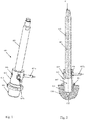
- Fig. 3 shows a brake release device 1 according to the invention, with its main components, the functional unit 100, an electric drive unit 200 and a tank assembly 300, which is penetrated by a control cylinder assembly 400.
- the cover 301 passes through the actuating piston 401 of the actuating cylinder arrangement 400. It also has a connecting eyelet 402 at its end.
- the adjusting piston 401 is in Fig. 1 in its rest position, ie in its retracted position (second working position) shown.
- a connection box 203 is attached.
- Fig. 1 shows in perspective view the actuating cylinder assembly 400. It comprises the actuating piston 401, which is slidably received in a cylinder tube 403. At the lower end of the cylinder tube 403, an external thread 404 is provided with which the cylinder tube can be screwed into a corresponding receptacle 101 of the functional unit 100 (cf. Fig. 2 ).
- Into the receptacle 101 opens an inlet and outlet 102, via which the interior 405 (pressure chamber) of the cylinder tube 403 is filled with hydraulic fluid. Serves a not shown electric pump unit.
- the pressure chamber 405 When filling the pressure chamber 405 with hydraulic fluid an internal pressure is built there, which brings the actuating piston 401 against a force acting on the upper end spring force F of the brake assembly not shown in its first working position. In this case, the adjusting piston 401 is fully extended and releases the brake assembly.
- the cylinder tube 403 has a plurality of bores 406 designed as bores, into which sensors 407 are inserted.
- the sensors 407 are designed as inductive sensors and have a directed into the interior of the cylinder tube 403 end face 408, which serves as a signal-triggering sensor element.
- the end face 408 detects the approach of an annular shoulder 409 of the actuating piston 401, which serves as a triggering element.
- the sensors 407a and 407b thus capture the in Fig. 2 shown first working position of the actuating piston 401, in which the shoulder 409 in the region of the end face 408 of the sensors 407a and 407b is arranged.
- the one sensor 407a outputs a corresponding switching signal to the pump unit and switches it off.
- the second sensor 407b outputs a signal as a position signal to any control device either of the brake release device 1 itself or to a control unit of a system, of which the brake release device 1 is an integral part. The signal indicates the state "Brake released”.
- the spring force F causes the actuating piston to move in the direction of the force in the direction of the functional unit 100.
- the shoulder 409 leaves the region of the end faces 408 of the sensor 407a, 407b.
- This changes its signal which optionally triggers a switching operation, which sets the hydraulic pump back into operation to rebuild the pressure so far that the actuating piston 401 moves back to its first working position.
- a signal which optionally indicates that the brake release device 1 is no longer in its "brake released" state.
- the distance of the end face 408 can be changed to the peripheral surface of the paragraph 409.
- the responsiveness of the sensor 407a, 407b with respect to a change in the axial position of the shoulder 409 along the axis 410 is adjustable. If the end face 408 is close to the shoulder 409, then the detection is very sensitive severely. The signal changes as soon as the peripheral surface reaches the area of the end face 408. If the end face 408 farther away, the detection is "blurred” and somewhat delayed, so only when the paragraph 409 is moved further into the region of the end face 408.
- the plurality of wreath-mounted receptacles 406 allow the sensors 407a, 407b to be screwed into receptacles 406 which provide the sensors 407 with a favorable circumferential orientation of the cylinder tube 403 in the functional unit 100.
- the cylinder tube 403 is fixed via a lock nut 411. Subsequently, the sensor or sensors 407a, 407b are inserted into the preferred receptacles 406 and fixed there.
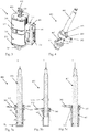
- Fig. 4 shows an embodiment of the actuating cylinder assembly 400 according to a second aspect of the invention.
- a further receiving arrangement is arranged on the cylinder tube 403, which is designed as a fixable outer ring 500.
- a receiving bore 501 is provided, in which a sensor 502 is mounted.
- This sensor 502 detects the position of an adjustable on the piston rod 412 triggering element, which is designed as a collar 503.
- Fig. 5a shows the actuating piston 401 in a so-called Resthub too, in which the adjusting piston 401 is brought when it is inserted under the action of the spring force F in the cylinder tube.
- the adjusting ring 503 is arranged so that it only comes into the effective range of the sensor 502 when the residual stroke H R falls below an adjustable limit.
- the residual stroke H R changes when the brake is used, with increasing wear of the brake elements (brake disc, brake pads). If, therefore, a certain residual stroke is undershot, the sensor 502 indicates this, namely when the adjusting ring 503 reaches the effective range of the sensor 502. This then sends a signal to a display and / or control device.
- the display device may be configured in the form of one or more LED elements 600, which emit a light signal in response to this switching signal.
- the light signal can be, for example, that a color change from green to red takes place or a blinking frequency is increased.
- This signal change then indicates a revision state, which is triggered by the reduction of the residual stroke H R or the undershooting of a minimum residual stroke.
- Fig. 5b shows the actuating cylinder assembly 401 in the extended state (see also Fig. 2 ). In this position, the adjusting ring 503 is not detected by the sensor 502.
- Fig. 5c shows the actuator piston 401 in the fully retracted position.
- the position of the adjusting ring 503 is detected by the sensor 502.
- the collar 503 does not serve to indicate a revision condition, but to represent a "brake-closed" condition.
- sensors 502 which are arranged in an axially offset position. One then signals the "brake closed” state and, if necessary, the revision state.
- the in the Fig. 5a to 5c arrangement shown can also with the in the Fig. 1 and 2 arrangements are shown combined. This can be used to combine the setting, control and display options.
Landscapes
- Engineering & Computer Science (AREA)
- General Engineering & Computer Science (AREA)
- Mechanical Engineering (AREA)
- Physics & Mathematics (AREA)
- Electromagnetism (AREA)
- Transportation (AREA)
- Braking Arrangements (AREA)
- Valves And Accessory Devices For Braking Systems (AREA)
Abstract
Die Erfindung betrifft ein Bremslüftgerät (1) mit einer hydraulischen Stellzylinderanordnung (400) zum Betätigen einer Bremsanordnung, wobei die Stellzylinderanordnung (400) ein Zylinderrohr (403) und einen im Zylinderrohr (403) zwischen einer ersten und zweiten Arbeitsstellung verstellbaren Stellkolben (401) umfasst, am Zylinderrohr (403) mehrere in Umfangsrichtung kranzartig angeordnete Aufnahmen (406) angeordnet sind, von denen wenigstens zwei einen Sensor (407a, 407b) tragen, der dazu ausgebildet ist, eine erste Arbeitsstellung des Stellkolbens (401) zu detektieren, wobei beim Detektieren der ersten Arbeitsstellung ein erster Sensor (407a) ein Schaltsignal an eine auf die Stellzylinderanordnung (400) wirkende Druckeinrichtung generiert und ein zweiter Sensor (407b) ein Schaltsignal an eine Steuerungseinrichtung abgibt.The invention relates to a brake release device (1) having a hydraulic actuating cylinder arrangement (400) for actuating a brake arrangement, wherein the actuating cylinder arrangement (400) comprises a cylinder tube (403) and an adjusting piston (401) adjustable in the cylinder tube (403) between a first and second working position on the cylinder tube (403) a plurality of circumferentially arranged receptacles (406) are arranged, of which at least two a sensor (407a, 407b) carry, which is adapted to detect a first operating position of the actuating piston (401), wherein upon detection the first working position, a first sensor (407a) generates a switching signal to a pressure device acting on the actuating cylinder arrangement (400) and a second sensor (407b) emits a switching signal to a control device.
Die Erfindung betrifft des Weiteren ein Bremslüftgerät (1) mit einer hydraulischen Stellzylinderanordnung (400) zum Betätigen einer Bremsanordnung, wobei die Stellzylinderanordnung (400) ein Zylinderrohr (403) und einen im Zylinderrohr (403) zwischen einer ersten und zweiten Arbeitsstellung verstellbaren Stellkolben (401) umfasst, wobei am Zylinderrohr (403) eine verstellbare Aufnahmeanordnung angeordnet ist, in der eine Aufnahme angeordnet ist, die einen Sensor (502) trägt, der dazu ausgebildet ist, eine zweite Arbeitsstellung des Stellkolbens (401) zu detektieren und beim Detektieren der zweiten Arbeitsstellung der Sensor (502) ein Signal an eine Anzeigevorrichtung abgibt, welche die zweite Arbeitsstellung anzeigt.

Description
Die vorliegende Offenbarung bezieht sich allgemein und insbesondere auf ein Bremslüftgerät mit einer hydraulischen Stellzylinderanordnung zum Betätigen einer Bremsanordnung, wobei die Stellzylinderanordnung ein Zylinderrohr und einen im Zylinderrohr zwischen einer ersten und zweiten Arbeitsstellung verstellbaren Stellkolben umfasst.The present disclosure relates generally and in particular to a brake release device with a hydraulic actuator cylinder assembly for actuating a brake assembly, wherein the actuator cylinder assembly comprises a cylinder tube and an adjustable in the cylinder tube between a first and second operating position control piston.
Es sind allgemein eine Vielzahl von federbelasteten Bremsanlagen bekannt, bei denen eine Federkraft über ein kraftverstärkendes Hebelsystem auf Bremselemente wirkt, die dann wiederum an einem entsprechenden Bremskörper (zum Beispiel einer Scheibe oder einer Trommel) angreifen. Sie sind in der Regel als Sicherheitsbremsen ausgelegt und arbeiten nach dem Fail-safe-Prinzip. Das heißt die Bremsen sind so ausgelegt, dass sie im Störfall, zum Beispiel bei einem Stromausfall, automatisch schließen und die zu bremsenden, bewegten Teile möglichst schnell zum Stillstand bringen oder in einer bestimmten Position festhalten (zum Beispiel bei Hebezeugen oder Aufzügen).There are generally a variety of spring-loaded brake systems are known in which a spring force acts on a force-enhancing lever system on brake elements, which in turn attack on a corresponding brake body (for example, a disc or a drum). They are usually designed as safety brakes and work on the fail-safe principle. This means that the brakes are designed so that they automatically close in the event of a fault, for example in the event of a power failure, and bring the moving parts to be braked to a standstill as quickly as possible or hold them in a specific position (for example, in the case of hoists or elevators).
Dazu ist es zunächst notwendig, die Bremsen in geöffnetem, also im gelüfteten Zustand zu halten. Dazu dienen sogenannte Bremslüftgeräte, welche im aktivierten Zustand gegen die Bremsfederkraft arbeiten, diese aufheben, die Bremse öffnen und im (geöffneten) gelüfteten Zustand festhalten. Besonders verbreitet sind elektrohydraulische Bremslüftgeräte, die parallel zur Bremsfeder auf das Bremshebelgestänge wirken.For this it is first necessary to keep the brakes in the open, ie in the released state. Serve so-called brake release devices, which work in the activated state against the brake spring force, these cancel, open the brake and hold in the (open) ventilated state. Particularly common are electro-hydraulic brake release devices that act on the brake lever linkage parallel to the brake spring.
Es gibt Bremslüftgeräte, die nach folgendem Prinzip arbeiten: Zum Lösen oder Lüften der Bremse wird ein Antrieb (in der Regel ein Elektromotor) in Bewegung versetzt. Dieser Antrieb wirkt auf eine Kreiselpumpe, die im Betrieb ein Hydraulikmedium unter Druck setzt und fördert, das seinerseits auf eine Zylinderkolbenfläche wirkt, die über eine Stellstange mit dem Bremshebelgestänge gekoppelt ist. Dabei wirkt bei einer bestimmten Drehzahl ein bestimmter Druck auf die Stellkolbenfläche, der wiederum eine bestimmte Stellkraft auf das Gestänge ausübt und so die Rückstellkraft der Bremsfeder neutralisiert und die Bremsanordnung im geöffneten Zustand hält.There are brake release devices that work according to the following principle: To release or release the brake, a drive (usually an electric motor) is set in motion. This drive acts on a centrifugal pump, which puts a hydraulic medium under pressure and promotes in operation, which in turn acts on a cylinder piston surface which is coupled via an actuating rod with the brake lever linkage. In this case, at a certain speed, a certain pressure acts on the actuating piston surface, which in turn exerts a certain actuating force on the linkage and thus neutralizes the restoring force of the brake spring and keeps the brake assembly in the opened state.
Ein anderer Ansatz besteht darin, ein Bremslüftgerät im Aussetzbetrieb zu betreiben, d. h. nach dem Aufbau eines bestimmten Betriebsdrucks am Zylinder wird dieser über geeignete Schaltventile gehalten und zum Bremsen wieder abgebaut. So ein Bremslüftgerät ist beispielsweise aus der
Zum Erfassen des erforderlichen Arbeitsdrucks (Verstelldruck) dient ein mechanischer Druckschalter, der bei Erreichen des Arbeitsdrucks ein entsprechendes Schaltsignal/Stoppsignal an einen elektrischen Antriebsmotor einer Hydraulikpumpe liefert. Bei mechanischen Druckschaltern kann es wegen interner Leckagen zu einem schnellen Druckabfall kommen, der zu einem unkontrollierten An- und Abschalten des Antriebsmotors führt. So ein Serienan- und abschalten des Antriebsmotors bzw. der Pumpe ist unerwünscht, führt zu hohem Verschleiß und gegebenenfalls zum Ausfall des Bremslüftgeräts.To detect the required working pressure (adjustment pressure) is a mechanical pressure switch, which supplies a corresponding switching signal / stop signal to an electric drive motor of a hydraulic pump on reaching the working pressure. With mechanical pressure switches, a rapid pressure drop can occur due to internal leakage, which leads to an uncontrolled switching on and off of the drive motor. Such a series connection and disconnection of the drive motor or the pump is undesirable, leads to high wear and possibly to the failure of the brake release device.
Aus der
Da die verwendeten Hydrauliköle eine sehr niedrige Viskosität aufweisen, kann es auch schon bei geringen Leckagen zu einem so starken Druckabbau kommen, dass der Druckschalter anspricht und die Pumpe aktiviert, selbst wenn die gewünschte Endstellung des Stellkolbens noch zuverlässig eingenommen wird.Since the hydraulic oils used have a very low viscosity, even at low leaks can lead to such a strong pressure reduction that the pressure switch responds and activates the pump, even if the desired end position of the actuating piston is still reliably taken.
Bei den oben dargestellten Bremslüftgeräten wird der die Bremsanordnung betätigende Bremskolben zwischen einer ersten Arbeitsstellung (ausgefahrener Zustand) und einer zweiten Arbeitsstellung (eingefahrener bzw. fast eingefahrener Zustand) im Betrieb hin-und-her verstellt. Die erste Arbeitsstellung betrifft dabei einen Lüft- bzw. Lösezustand und die zweite Arbeitsstellung den Bremszustand. Die zweite Arbeitsstellung verändert sich jedoch im Laufe der Zeit, und zwar dadurch, dass sich die eigentlichen Bremselemente (Bremsbacken und Bremsscheiben) bei wiederholten Bremsvorgängen abnutzen. Das bedeutet, im Laufe der Zeit verschiebt sich die zweite Arbeitsstellung dahingehend, dass der Bremskolben im Bremszustand (Bremslüftgerät deaktiviert) immer weiter eingefahren wird.In the brake release devices shown above, the brake assembly actuating brake piston between a first working position (extended state) and a second working position (retracted or almost retracted state) in the operation back and forth adjusted. The first working position relates to a release or release state and the second working position refers to the braking state. However, the second working position changes over time due to the fact that the actual brake elements (brake shoes and brake discs) wear out during repeated braking processes. This means that, over time, the second working position shifts to the point that the brake piston is retracted further and further in the braking state (brake release device deactivated).
Das heißt der sogenannte Resthub des Kolbens verringert sich immer mehr in dem Maße, wie sich die Bremselemente abnutzen. Da die Veränderung des Resthubs ein Maß für den Verschleiß für die Bremselemente ist, ist es bisher üblich, den Resthub durch regelmäßige Inaugenscheinnahme des Kolbenwegs über dort angebrachte Markierungen festzustellen. Wird ein stark verringerter Resthub festgestellt oder eine Unterschreitung eines Mindestresthubs, so werden die entsprechenden Bauteile in einer Revision ausgewechselt bzw. überarbeitet (Austausch der Bremsbacken, Austausch der Bremsscheibe). Diese regelmäßige Überwachung des Resthubs ist aufwändig und bei Bremsanlagen, die schwer zugänglich sind, aufwändig und teuer.That is, the so-called residual stroke of the piston decreases more and more as the brake elements wear. Since the change in the residual stroke is a measure of the wear on the brake elements, it has been customary to determine the remaining stroke by regular inspection of the piston stroke on there markings. Will a greatly reduced residual stroke If a minimum residual stroke has been detected or undershot, the corresponding components are replaced or revised in a revision (replacement of the brake shoes, replacement of the brake disk). This regular monitoring of the residual stroke is complex and costly in brake systems that are difficult to access.
Es gibt Anwendungen, bei denen die Bremslüftgeräte so schwer zugänglich sind, dass einen regelmäßige Überwachung nicht lohnt, sondern die Verschleißteile in regelmäßigen Abständen ausgetauscht werden, selbst dann wenn es nicht erforderlich wäre. Dies erhöht die Betriebskosten solcher Anlagen.There are applications where the brake release devices are so inaccessible that regular monitoring is not worthwhile, but the wearing parts are replaced at regular intervals, even if it were not necessary. This increases the operating costs of such systems.
Aufgabe ist es, ein verbessertes Bremslüftgerät zur Verfügung zu stellen.The task is to provide an improved brake release device.
Nach einem ersten Aspekt zeigt die vorliegende Offenbarung ein Bremslüftgerät mit einer hydraulischen Stellzylinderanordnung zum Betätigen einer Bremsanordnung, wobei die Stellzylinderanordnung ein Zylinderrohr und einen im Zylinderrohr zwischen einer ersten und zweiten Arbeitsstellung verstellbaren Stellkolben umfasst und am Zylinderrohr mehrere in Umfangsrichtung kranzartig angeordnete Aufnahmen angeordnet sind, von denen wenigstens zwei einen Sensor tragen, der dazu ausgebildet ist, eine erste Arbeitsstellung des Stellkolbens zu detektieren, wobei beim Detektieren der ersten Arbeitsstellung ein erster Sensor ein Schaltsignal an eine auf die Stellzylinderanordnung wirkende Druckeinrichtung generiert und ein zweiter Sensor ein Schaltsignal an eine Steuerungseinrichtung abgibt.According to a first aspect, the present disclosure shows a brake release device with a hydraulic actuating cylinder arrangement for actuating a brake assembly, wherein the actuating cylinder arrangement comprises a cylinder tube and an adjustable in the cylinder tube between a first and second working position control piston and the cylinder tube a plurality of circumferentially arranged receptacles are arranged from where at least two carry a sensor which is adapted to detect a first working position of the actuating piston, wherein upon detection of the first working position, a first sensor generates a switching signal to a force acting on the actuating cylinder pressure device and a second sensor emits a switching signal to a control device.
Nach einem zweiten Aspekt der vorliegenden Erfindung wird ein Bremslüftgerät mit einer hydraulischen Stellzylinderanordnung zum Betätigen einer Bremsanordnung bereitgestellt, wobei die Stellzylinderanordnung ein Zylinderrohr und einen im Zylinderrohr zwischen einer ersten und zweiten Arbeitsstellung verstellbaren Stellkolben umfasst, wobei am Zylinderrohr eine verstellbare Aufnahmeanordnung angeordnet ist, in der eine Aufnahme angeordnet ist, die einen Sensor trägt, der dazu ausgebildet ist, eine zweite Arbeitsstellung des Stellkolbens zu detektieren und beim Detektieren der zweiten Arbeitsstellung der Sensor ein Signal an eine Anzeigevorrichtung abgibt, welche die zweite Arbeitsstellung anzeigt.According to a second aspect of the present invention, a brake release device is provided with a hydraulic actuating cylinder arrangement for actuating a brake assembly, wherein the actuating cylinder arrangement comprises a cylinder tube and an adjustable piston in the cylinder tube between a first and second operating position, wherein on the cylinder tube an adjustable receiving arrangement is arranged, in the a receptacle is arranged, which carries a sensor which is adapted to detect a second operating position of the actuating piston and emits a signal to a display device, which indicates the second working position upon detection of the second operating position of the sensor.
Weitere Aspekte und Merkmale ergeben sich aus den abhängigen Ansprüchen, der beigefügten Zeichnung und der nachfolgenden Beschreibung von Ausführungsformen.Other aspects and features will become apparent from the dependent claims, the accompanying drawings and the following description of embodiments.
Ausführungsformen werden nun beispielhaft und unter Bezugnahme auf die beigefügte Zeichnung beschrieben. Darin zeigt:
- Fig. 1
- eine perspektivische Ansicht einer ersten Ausführungsform einer Stellzylinderanordnung für ein erfindungsgemäßes Bremslüftgerät;
- Fig 2
- eine Schnittdarstellung der in
Fig. 1 gezeigten Stellzylinderanordnung im Einbauzustand; - Fig. 3
- eine perspektivische Ansicht eines erfindungsgemäßen Bremslüftgeräts;
- Fig. 4
- eine perspektivische Ansicht einer zweiten Ausführungsform einer Stellzylinderanordnung für ein erfindungsgemäßes Bremslüftgerät und
- Fig. 5a bis 5c
- Schnittdarstellungen der in
Fig. 4 gezeigten Stellzylinderanordnung in unterschiedlichen Betriebsstellungen
- Fig. 1
- a perspective view of a first embodiment of a control cylinder assembly for a brake release device according to the invention;
- Fig. 2
- a sectional view of in
Fig. 1 shown actuating cylinder assembly in the installed state; - Fig. 3
- a perspective view of a brake release device according to the invention;
- Fig. 4
- a perspective view of a second embodiment of a control cylinder assembly for a brake release device according to the invention and
- Fig. 5a to 5c
- Sectional views of in
Fig. 4 shown actuating cylinder assembly in different operating positions
Vor einer detaillierten Beschreibung der Ausführungsform unter Bezugnahme auf
Die Erfindung gemäß dem ersten Aspekt zeichnet sich dadurch aus, dass am Zylinderrohr mehrere in Umfangsrichtung kranzartig angeordnete Aufnahmen angeordnet sind, von denen wenigstens zwei einen Sensor tragen, die jeweils dazu ausgebildet ist, eine erste Arbeitsstellung, insbesondere die Endstellung des Stellkolbens im ausgefahrenen Zustand, zu detektieren und zu signalisieren.The invention according to the first aspect is characterized in that a plurality of circumferentially arranged receptacles are arranged on the cylinder tube, of which at least two carry a sensor, which is each adapted to a first working position, in particular the end position of the actuating piston in the extended state, to detect and signal.
Der erste Sensor generiert dabei ein Schalt- oder Stellsignal an eine auf die Stellzylinderanordnung wirkende Druckeinrichtung (z. B. elektronischer Antriebsmotor einer Pumpe) und der zweite Sensor gibt ein weiteres entsprechendes Signal an eine Steuerungseinrichtung ab (z. B. über eine Datenleitung oder ein Datenbussystem).The first sensor generates a switching or actuating signal to a pressure device acting on the actuating cylinder arrangement (eg electronic drive motor of a pump) and the second sensor outputs another corresponding signal to a control device (eg via a data line or a data bus system).
Dadurch, dass am Zylinderrohr mehrere in Umfangsrichtung kranzartig angeordnete Aufnahmen angeordnet sind, ist es möglich, die Sensoren wahlweise an unterschiedlichen Positionen anzubringen. Damit kann das Zylinderrohr, das beispielsweise in eine Druckaufnahme eingeschraubt wird, unabhängig von dessen endgültiger Drehstellung nach dem Einschrauben im bevorzugten Umfangssektor mit Sensoren bestückt werden, die dann an einer gewünschten, gut zugänglichen Position radial vom Zylinderrohr abstehen.Characterized in that a plurality of circumferentially arranged in a wreath-like receptacles are arranged on the cylinder tube, it is possible to attach the sensors optionally at different positions. Thus, the cylinder tube, which is screwed, for example, in a pressure receptacle, regardless of its final rotational position after screwing in the preferred circumferential sector are equipped with sensors, which then protrude radially at a desired, easily accessible position from the cylinder tube.
Dadurch, dass nicht der Druck im System, sondern die Arbeitsstellung des Stellkolbens im Zylinderrohr detektiert wird, können kleine Druckschwankungen im System auftreten, ohne dass eine Betätigung der Druckeinrichtung stattfindet, da sich die Stellung des Stellkolbens nicht verändert. Die Druckeinrichtung wird erst dann wieder geschaltet, wenn der Stellkolben seine erste Arbeitsstellung verlässt bzw. um einen bestimmbaren Betrag so weit von dieser Arbeitsstellung abweicht (weiter eingefahrener Zustand), dass diese Stellungsveränderung von den Sensoren detektiert wird und diese ein entsprechendes Signal abgeben.The fact that not the pressure in the system, but the working position of the actuating piston is detected in the cylinder tube, small pressure fluctuations in the system can occur without an actuation of the pressure device takes place, since the position of the actuating piston does not change. The pressure device is only switched again when the actuating piston leaves its first working position or deviates so far from this working position by a determinable amount (further retracted state) that this position change is detected by the sensors and they emit a corresponding signal.
Als Druckeinrichtung kann hier eine elektrisch angetriebene Druckpumpe oder aber auch ein großvolumiger Druckspeicher mit entsprechenden Stellventilen dienen.As a pressure device can serve here an electrically driven pressure pump or even a large-volume pressure accumulator with corresponding control valves.
Der zweite Sensor dient dazu, ein Schaltsignal an eine zusätzliche Steuerungseinrichtung abzugeben. Dies kann beispielsweise eine übergeordnete Steuerung sein (beispielsweise eines Krans), bei der die Bremsanordnung bzw. das Bremslüftgerät eine Komponente darstellt.The second sensor serves to deliver a switching signal to an additional control device. This may be, for example, a higher-level control (for example, a crane), in which the brake assembly or the brake release device is a component.
Dabei gibt es Ausführungen, bei denen der Sensor als induktiver Sensor ausgebildet ist, der die Stellung eines an der Kolbenstange ausgebildeten ersten Auslöseelements erfasst, welches in der ersten Arbeitsstellung im Wirkbereich eines signalauslösenden Sensorelements des Sensors angeordnet ist. Induktive Sensoren oder induktive Näherungsschalter sind besonders zuverlässig und geeignet, die Position eines Stellelements genau zu erfassen, welches in den Wirkbereich eines signalauslösenden Sensorelements gelangt. In der Regel dient eine aktive Sensorfläche, die an der Stirnseite eines induktiven Näherungsschalters angeordnet ist, als signalauslösendes Stellelement.There are embodiments in which the sensor is designed as an inductive sensor, which detects the position of a formed on the piston rod first triggering element, which is arranged in the first working position in the effective range of a signal-triggering sensor element of the sensor. Inductive sensors or inductive proximity switches are particularly reliable and suitable for accurately detecting the position of an actuating element which enters the effective range of a signal-triggering sensor element. As a rule, an active sensor surface, which is arranged on the end face of an inductive proximity switch, serves as a signal-triggering actuating element.
Es gibt Ausführungen, bei denen die Sensoren und Aufnahmen so aufeinander abgestimmt sind, dass der Abstand eines signalauslösenden Sensorelements (zum Beispiel der aktiven Sensorfläche) zum Auslöseelement einstellbar ist, so dass das Schaltsignal der Sensoren in einer von der ersten Arbeitsstellung abweichenden Pilotarbeitsstellung ausgelöst werden kann. Die Einstellbarkeit eines Sensorelements erlaubt es, das Ansprechverhalten des Sensors in gewünschter Weise so zu verändern, dass der Sensor früher oder später bzw. bei größerer oder geringerer Nähe des Auslöseelements bereits auslöst.There are embodiments in which the sensors and recordings are coordinated so that the distance between a signal-triggering sensor element (for example, the active sensor surface) is adjustable to the trigger element, so that the switching signal of the sensors can be triggered in a deviating from the first working position pilot work position , The adjustability of a sensor element makes it possible to change the response of the sensor in the desired manner so that the sensor sooner or later or at greater or lesser proximity of the trigger element already triggers.
Das Erfassen einer Pilotarbeitsstellung kann beispielsweise dann sinnvoll sein, wenn eine Antriebspumpe ein bestimmtes Nachlaufverhalten hat, d.h. dass sie eine gewisse Nachpumpwirkung aufweist, die dazu ausreicht, den Kolben in die eigentliche Endarbeitsstellung zu bringen. Wird dazu das Nachlaufverhalten der Pumpe genutzt, so wird die gewünschte Arbeitsstellung schonender eingestellt, nämlich ohne dass der Kolben mit schlagartiger Verzögerung an seinen Anschlag ausgefahren wird.The detection of a pilot work position can be useful, for example, when a drive pump has a certain follow-up behavior, i. that it has a certain Nachpumpwirkung, which is sufficient to bring the piston in the actual final working position. If the follow-up behavior of the pump is used for this purpose, the desired working position is set more gently, namely without the piston being extended to its stop with a sudden delay.
Es gibt Ausführungen, bei denen das Auslöseelement im Inneren des Zylinderrohrs angeordnet ist. In diesem Fall kann das eigentliche Auslöseelement ein Kolbenabsatz sein, der den Druckraum gegen die Umgebung abdichtet und/oder ein Ende des Kolbens im Zylinderrohr führt. Eine solche Nutzung bereits vorhandener Bauteile vereinfacht das erfindungsgemäße Bremslüftgerät.There are versions in which the trigger element is arranged in the interior of the cylinder tube. In this case, the actual triggering element may be a piston shoulder, which seals the pressure chamber from the environment and / or leads one end of the piston in the cylinder tube. Such use of already existing components simplifies the brake release device according to the invention.
Gemäß dem zweiten Aspekt der Erfindung zeichnet sich das erfindungsgemäße Bremslüftgerät dadurch aus, dass am Zylinderrohr eine verstellbare Aufnahmeanordnung angeordnet ist, in der eine Aufnahme angeordnet ist, die einen Sensor trägt, der dazu ausgebildet ist, eine zweite Arbeitsstellung des Stellkolbens zu detektieren und der Sensor beim Detektieren der zweiten Arbeitsstellung ein Signal an eine Anzeigevorrichtung abgibt, welche die zweite Arbeitsstellung anzeigt. Bei der zweiten Arbeitsstellung handelt es sich typischerweise um den eingefahrenen oder fast eingefahrenen Zustand des Stellkolbens. Sie signalisiert dann z. B. den "Bremse geschlossen"-Zustand.According to the second aspect of the invention, the brake release device according to the invention is characterized in that the cylinder tube an adjustable receiving arrangement is arranged, in which a receptacle is arranged, which carries a sensor which is adapted to a second working position to detect the actuating piston and the sensor emits a signal to a display device, which indicates the second working position when detecting the second working position. The second working position is typically the retracted or almost retracted state of the actuating piston. It then signals z. B. the "brake closed" state.
Dabei gibt es Ausführungen, bei denen die zweite Arbeitsstellung eine Revisionsstellung, insbesondere eine Resthubstellung des Bremslüftgeräts anzeigt. Damit ist es möglich, ggf. per Ferndiagnose, eine (Grenz- oder Mindest-)-Resthubstellung zu erkennen, ohne dass dazu eine genaue Inspektion der Bremse vor Ort erforderlich wäre.There are embodiments in which the second working position indicates a revision position, in particular a residual stroke position of the brake release device. This makes it possible, if necessary by remote diagnosis, to detect a (limit or minimum) residual stroke position without requiring an exact inspection of the brake on site.
Es gibt Ausführungen, bei welchen die Aufnahmevorrichtung in einer Umfangsrichtung und/oder in einer axialen Richtung zu einer Längsachse der Stellzylinderachse verstellbar ist. Damit lässt sich die Position des Sensors bzw. eines signalauslösenden Sensorelements in gewünschter Weise zur Kolbenstange anordnen.There are embodiments in which the receiving device is adjustable in a circumferential direction and / or in an axial direction to a longitudinal axis of the actuating cylinder axis. This allows the position of the sensor or a signal-triggering sensor element arranged in the desired manner to the piston rod.
Dabei gibt es Ausführungen, bei welchen der Sensor als induktiver Sensor ausgebildet ist, der die Stellung eines an der Kolbenstange verstellbar angeordneten Auslöseelements erfasst, welches in der zweiten Arbeitsstellung im Wirkbereich eines signalauslösenden Sensorelements angeordnet ist. Auf diese Weise ist es möglich, die Stellzylinderanordnung mit Sensor und Auslöseelement so aufeinander abzustimmen, dass die gewünschte zweite Arbeitsstellung genau und individuell einstellbar ist.There are embodiments in which the sensor is designed as an inductive sensor which detects the position of an adjustable on the piston rod triggering element, which is arranged in the second working position in the effective range of a signal-triggering sensor element. In this way, it is possible to match the actuating cylinder arrangement with the sensor and triggering element to one another such that the desired second working position is precisely and individually adjustable.
Dabei gibt es Ausführungen, bei welchen das Auslöseelement als ein auf der Kolbenstange fixierbarer Stellring ausgebildet ist. Dies stellt eine besonders einfache, flexible, nachrüstbare und robuste Lösung dar.There are embodiments in which the triggering element is designed as a fixable on the piston rod collar. This represents a particularly simple, flexible, retrofittable and robust solution.
Es gibt Ausführungen, bei welchen die Anzeigevorrichtung eine optische Anzeigevorrichtung, insbesondere eine LED-Anzeigevorrichtung, ist. Damit wird die zweite Arbeitsstellung deutlich optisch signalisiert. Die Ausführung als LED-Anzeige ist robust, langlebig und energiesparend. So kann beispielsweise durch einen signalisierten Farbwechsel (zum Beispiel von Rot nach Grün) das Einnehmen der zweiten Arbeitsstellung signalisiert werden, insbesondere dann, wenn es sich dabei um eine Revisionsstellung (Mindestresthub erreicht) handelt.There are embodiments in which the display device is a visual display device, in particular an LED display device. Thus, the second working position is clearly optically signaled. The version as LED display is robust, durable and energy-saving. Thus, for example, by a signaled color change (for example, from red to green), the ingestion of the second working position can be signaled, especially if this is a revision position (Mindestresthub achieved).
Es gibt Ausführungen, bei denen die Anzeigevorrichtung an einer (gut einsehbaren) Außenfläche des Bremslüftgeräts angeordnet ist und so ausgebildet ist, dass bei Erreichen der zweiten Arbeitsstellung ein Lichtsignal ausgesendet oder verändert wird. Dieses Lichtsignal ist auch von weitem wahrzunehmen, über eine optische Erfassungseinrichtung (Überwachungskamera) oder auch mit bloßem Auge.There are embodiments in which the display device is arranged on a (easily visible) outer surface of the brake release device and is designed so that when reaching the second working position, a light signal is transmitted or changed. This light signal can also be perceived from afar, via an optical detection device (surveillance camera) or even with the naked eye.
Es gibt Ausführungen, bei denen die Lösung gemäß dem ersten Aspekt der Erfindung und gemäß dem zweiten Aspekt der Erfindung miteinander kombiniert wird. Bei so einer Lösung wird sowohl die erste Arbeitsstellung (zum Beispiel der ausgefahrene Zustand des Stellkolbens) und die zweite Arbeitsstellung (zum Beispiel der eingefahrene Zustand bzw. die Resthub- oder Revisionsstellung) mithilfe geeigneter Sensoren erfasst werden. Die dabei erfassten Schaltsignale können dabei in beliebiger Kombination zur
- Steuerung des Bremslüftgeräts oder seiner Komponenten,
- zur Anzeige der Arbeitsstellungen über am Bremslüftgerät selbst vorgesehene Anzeigevorrichtungen,
- zur Anzeige der Arbeitsstellungen an anderen Anzeigegeräten und
- zur Bedatung von übergeordneten externen und/oder internen Steuergeräten genutzt werden.
- Control of the brake release device or its components,
- for displaying the working positions via display devices provided on the brake release device itself,
- to display the working positions on other display devices and
- used for the parameterization of higher-level external and / or internal ECUs.
Nun zurückkehrend zu den Figuren.
In die Aufnahme 101 mündet ein Zu- und Abfluss 102, über den das Innere 405 (Druckkammer) des Zylinderrohrs 403 mit Hydraulikflüssigkeit gefüllt wird. Dazu dient eine nicht weiter dargestellte elektrische Pumpeinheit. Beim Füllen der Druckkammer 405 mit Hydraulikflüssigkeit wird dort ein Innendruck aufgebaut, der den Stellkolben 401 gegen eine auf das obere Ende wirkende Federkraft F der nicht weiter dargestellten Bremsanordnung in seine erste Arbeitsstellung bringt. Dabei wird der Stellkolben 401 vollständig ausgefahren und löst die Bremsanordnung.Into the
Im Zylinderrohr 403 sind mehrere als Bohrungen ausgeführte Aufnahmen 406 vorgesehen, in die Sensoren 407 eingesetzt sind. Die Sensoren 407 sind als induktive Sensoren ausgebildet und weisen eine ins Innere des Zylinderrohrs 403 gerichtete Stirnfläche 408 auf, die als signalauslösendes Sensorelement dient. Die Stirnfläche 408 erfasst die Annäherung eines ringförmigen Absatzes 409 des Stellkolbens 401, der als Auslöseelement dient.The
Die Sensoren 407a und 407b erfassen also die in
Dabei gibt der eine Sensor 407a ein entsprechendes Schaltsignal an die Pumpeinheit und schaltet diese ab. Der zweite Sensor 407b gibt ein Signal als Stellungssignal an eine beliebige Steuereinrichtung entweder des Bremslüftgeräts 1 selbst oder an ein Steuergerät einer Anlage, von der das Bremslüftgerät 1 ein Bestandteil ist. Das Signal zeigt den Zustand "Bremse gelüftet" an.In this case, the one
Bei einem Druckabfall in der Kammer 405 bewirkt die Federkraft F, dass sich der Stellkolben in Kraftrichtung in Richtung Funktionseinheit 100 bewegt. Dabei verlässt der Absatz 409 den Bereich der Stirnflächen 408 des Sensors 407a, 407b. Dadurch verändert sich dessen Signal, das gegebenenfalls einen Schaltvorgang auslöst, der die Hydraulikpumpe wieder in Betrieb setzt, um den Druck wieder so weit aufzubauen, dass sich der Stellkolben 401 wieder in seine erste Arbeitsstellung bewegt. Weiter kann aber auch ein Signal genutzt werden werden, das gegebenenfalls anzeigt, dass das Bremslüftgerät 1 nicht mehr in seinem "Bremse gelüftet"-Zustand ist.When there is a pressure drop in the
Über die Anordnung der Sensoren 407 in den Aufnahmen 406 kann der Abstand der Stirnfläche 408 zur Umfangsfläche des Absatzes 409 verändert werden. Damit ist die Ansprechempfindlichkeit des Sensors 407a, 407b bezüglich einer Veränderung der Axialposition des Absatzes 409 entlang der Achse 410 einstellbar. Ist die Stirnfläche 408 nah am Absatz 409, so erfolgt die Detektion sehr empfindlich trennscharf. Das Signal verändert sich, sobald die Umfangsfläche in den Bereich der Stirnfläche 408 gelangt. Ist die Stirnfläche 408 weiter entfernt, erfolgt die Detektion "verschwommener" und etwas verzögerter, also erst dann, wenn der Absatz 409 weiter in den Bereich der Stirnfläche 408 verschoben ist.About the arrangement of the
Die mehreren kranzartig angebrachten Aufnahmen 406 erlauben es, die Sensoren 407a, 407b in solche Aufnahmen 406 einzuschrauben, die für die Sensoren 407 eine günstige Umfangsorientierung des Zylinderrohrs 403 in der Funktionseinheit 100 bieten. In dieser Einschraublage wird das Zylinderrohr 403 über eine Kontermutter 411 fixiert. Anschließend werden der oder die Sensoren 407a, 407b in die bevorzugten Aufnahmen 406 eingesetzt und dort fixiert.The plurality of wreath-mounted
Die Stellung in
Wir der Resthub HR völlig aufgebraucht (
Die Anzeigevorrichtung kann in Form von einem oder mehreren LED-Elementen 600 ausgestaltet werden, die auf dieses Schaltsignal hin ein Lichtsignal aussenden. Das Lichtsignal kann beispielsweise darin bestehen, dass ein Farbwechsel von grün nach rot stattfindet oder eine Blinkfrequenz erhöht wird. Dieser Signalwechsel zeigt dann einen Revisionszustand an, der über die Verringerung des Resthubs HR bzw. die Unterschreitung eines minimalen Resthubs ausgelöst wird.
Es können auch zwei Sensoren 502 vorgesehen werden, die in axial versetzter Lage angeordnet sind. Einer signalisiert dann den "Bremse geschlossen"-Zustand und einer ggf. den Revisionszustand.It can also be provided two
Die in den
Weitere Ausführungen und Variationen der Erfindung ergeben sich für den Fachmann im Rahmen der Ansprüche.Further embodiments and variations of the invention will become apparent to those skilled in the scope of the claims.
- 11
- Bremslüftgerätbrake lifting device
- 100100
- Funktionseinheitfunctional unit
- 101101
- Aufnahmeadmission
- 102102
- Zu-und AbflussInflow and outflow
- 200200
- elektrische Antriebseinheitelectric drive unit
- 201201
- Bodenground
- 202202
- Anschlussösenon lugs
- 203203
- Anschlusskastenjunction box
- 300300
- Tankbaugruppetank assembly
- 400400
- StellzylinderanordnungActuating cylinder arrangement
- 401401
- Stellkolbenactuating piston
- 402402
- Öseeyelet
- 403403
- Zylinderrohrcylinder tube
- 404404
- Außengewindeexternal thread
- 405405
- Kammerchamber
- 406406
- AufnahmenRecordings
- 407407
- Sensoren (407a, 407b)Sensors (407a, 407b)
- 408408
- Stirnflächeface
- 409409
- Absatzparagraph
- 410410
- Längsachselongitudinal axis
- 411411
- Kontermutterlocknut
- 412412
- Kolbenstangepiston rod
- 500500
- Außenringouter ring
- 501501
- Aufnahmebohrunglocation hole
- 502502
- Sensorsensor
- 503503
- Stellringcollar
- 600600
- LED-Einrichtung/LED-ElementLED device / LED element
Claims (11)
am Zylinderrohr (403) mehrere in Umfangsrichtung kranzartig angeordnete Aufnahmen (406) angeordnet sind, von denen wenigstens zwei einen Sensor (407a, 407b) tragen, der dazu ausgebildet ist, eine erste Arbeitsstellung des Stellkolbens (401) zu detektieren, wobei beim Detektieren der ersten Arbeitsstellung ein erster Sensor (407a) ein Schaltsignal an eine auf die Stellzylinderanordnung (400) wirkende Druckeinrichtung generiert und ein zweiter Sensor (407b) ein Schaltsignal an eine Steuerungseinrichtung abgibt.Brake release device (1) with a hydraulic actuating cylinder arrangement (400) for actuating a brake arrangement, wherein the actuating cylinder arrangement (400) comprises a cylinder tube (403) and an adjusting piston (401) which is adjustable in the cylinder tube (403) between a first and second operating position,
on the cylinder tube (403) a plurality of circumferentially arranged receptacles (406) are arranged, of which at least two a sensor (407a, 407b) carry, which is adapted to detect a first working position of the actuating piston (401), wherein when detecting the first operating position, a first sensor (407a) generates a switching signal to a pressure device acting on the actuating cylinder arrangement (400) and a second sensor (407b) emits a switching signal to a control device.
am Zylinderrohr (403) eine verstellbare Aufnahmeanordnung angeordnet ist, in der eine Aufnahme angeordnet ist, die einen Sensor (502) trägt, der dazu ausgebildet ist, eine zweite Arbeitsstellung des Stellkolbens (401) zu detektieren und beim Detektieren der zweiten Arbeitsstellung der Sensor (502) ein Signal an eine Anzeigevorrichtung abgibt, welche die zweite Arbeitsstellung anzeigt.Brake release device (1) with a hydraulic actuating cylinder assembly (400) for actuating a brake assembly, wherein the actuating cylinder assembly (400) comprises a cylinder tube (403) and an adjustable in the cylinder tube (403) between a first and second operating position adjusting piston (401),
on the cylinder tube (403) an adjustable receiving arrangement is arranged, in which a receptacle is arranged, which carries a sensor (502) which is adapted to a second operating position of Control piston (401) to detect and on detection of the second operating position of the sensor (502) emits a signal to a display device which indicates the second working position.
Priority Applications (2)
| Application Number | Priority Date | Filing Date | Title |
|---|---|---|---|
| RS20200388A RS60100B1 (en) | 2017-04-21 | 2018-04-17 | Brake lifting device with an actuation cylinder arrangement |
| PL18167726T PL3392106T3 (en) | 2017-04-21 | 2018-04-17 | Brake lifting device with an actuation cylinder arrangement |
Applications Claiming Priority (1)
| Application Number | Priority Date | Filing Date | Title |
|---|---|---|---|
| DE102017108489.4A DE102017108489A1 (en) | 2017-04-21 | 2017-04-21 | BRAKE VENTILATOR WITH CYLINDER ASSEMBLY |
Publications (3)
| Publication Number | Publication Date |
|---|---|
| EP3392106A2 true EP3392106A2 (en) | 2018-10-24 |
| EP3392106A3 EP3392106A3 (en) | 2018-12-12 |
| EP3392106B1 EP3392106B1 (en) | 2020-03-04 |
Family
ID=62091661
Family Applications (1)
| Application Number | Title | Priority Date | Filing Date |
|---|---|---|---|
| EP18167726.1A Active EP3392106B1 (en) | 2017-04-21 | 2018-04-17 | Brake lifting device with an actuation cylinder arrangement |
Country Status (6)
| Country | Link |
|---|---|
| EP (1) | EP3392106B1 (en) |
| DE (1) | DE102017108489A1 (en) |
| DK (1) | DK3392106T3 (en) |
| ES (1) | ES2785123T3 (en) |
| PL (1) | PL3392106T3 (en) |
| RS (1) | RS60100B1 (en) |
Family Cites Families (15)
| Publication number | Priority date | Publication date | Assignee | Title |
|---|---|---|---|---|
| US2276591A (en) * | 1940-07-27 | 1942-03-17 | William R Ray | Operator |
| US3828556A (en) * | 1973-01-26 | 1974-08-13 | Johnson Service Co | Hydraulic actuator |
| DE3400600A1 (en) * | 1983-02-18 | 1984-08-23 | Lucas Industries P.L.C., Birmingham, West Midlands | Actuating device for a brake, in particular a full-lining disc brake |
| US4936143A (en) | 1989-04-28 | 1990-06-26 | Eaton Corporation | Cylinders having piston position measurement |
| DE29521637U1 (en) | 1995-01-26 | 1997-12-11 | Rotovolumetric Ag | Device with a cylinder, a piston displaceable in this and an inductive transducer arranged in the cylinder |
| DE19955270A1 (en) | 1999-11-17 | 2001-05-23 | Roemheld A Gmbh & Co Kg | System for monitoring hydraulic cylinders including working cylinders and positioning cylinders e.g. for clamping and tightening engineering, includes sensors for detecting position |
| CN101166906A (en) | 2005-06-21 | 2008-04-23 | 麻电子工业株式会社 | Cylinder control unit |
| JP4847060B2 (en) * | 2005-07-15 | 2011-12-28 | 日立オートモティブシステムズ株式会社 | AC motor drive device and control method thereof |
| JP4529093B2 (en) * | 2007-12-19 | 2010-08-25 | Smc株式会社 | Piston position detection device for fluid pressure cylinder |
| DE102011085273A1 (en) * | 2010-11-05 | 2012-05-10 | Continental Teves Ag & Co. Ohg | Brake assembly for motor car, has hydraulic chamber acted upon pressure delivered by pressure provision device, where force effect is produced on master brake cylinder piston by pressurization of hydraulic chamber along operation direction |
| DE102012205859A1 (en) | 2011-04-19 | 2012-10-25 | Continental Teves Ag & Co. Ohg | Brake system for motor vehicles and method for operating a brake system |
| DE102012212836A1 (en) * | 2011-08-17 | 2013-02-21 | Continental Teves Ag & Co. Ohg | Braking system for motor vehicle, comprises power input piston guided in borehole of housing along actuation axis in movable manner, and simulation device is provided, which is hydraulically connected with hydraulic pressure chamber |
| DE102011114072C5 (en) * | 2011-09-22 | 2021-04-22 | Knorr-Bremse Systeme für Nutzfahrzeuge GmbH | Driver assistance system with autonomous braking to a standstill |
| DE102013105446A1 (en) | 2013-05-28 | 2014-12-04 | Pintsch Bubenzer Gmbh | Electro-hydraulic brake release device and brake assembly |
| DE102013105445B4 (en) | 2013-05-28 | 2015-08-20 | Pintsch Bubenzer Gmbh | Function unit and electro-hydraulic brake release device with such a |
-
2017
- 2017-04-21 DE DE102017108489.4A patent/DE102017108489A1/en active Pending
-
2018
- 2018-04-17 ES ES18167726T patent/ES2785123T3/en active Active
- 2018-04-17 EP EP18167726.1A patent/EP3392106B1/en active Active
- 2018-04-17 PL PL18167726T patent/PL3392106T3/en unknown
- 2018-04-17 DK DK18167726.1T patent/DK3392106T3/en active
- 2018-04-17 RS RS20200388A patent/RS60100B1/en unknown
Also Published As
| Publication number | Publication date |
|---|---|
| ES2785123T3 (en) | 2020-10-06 |
| PL3392106T3 (en) | 2020-08-24 |
| DE102017108489A1 (en) | 2018-10-25 |
| DK3392106T3 (en) | 2020-06-08 |
| RS60100B1 (en) | 2020-05-29 |
| EP3392106B1 (en) | 2020-03-04 |
| EP3392106A3 (en) | 2018-12-12 |
Similar Documents
| Publication | Publication Date | Title |
|---|---|---|
| DE69914968T2 (en) | Electro-hydraulic control unit | |
| DE102012018134B4 (en) | Brake master cylinder | |
| DE102010028762A1 (en) | Device for determining an operating state of at least one bidirectionally actuable hydraulic adjusting device of a switching element of a transmission device | |
| DE102015104133A1 (en) | Clamping device for stretching a threaded bolt | |
| DE102016223802A1 (en) | Detection device and lubricant distributor | |
| EP3438511A1 (en) | Slide ring seal arrangement of a hydrodynamic retarder, and hydrodynamic retarder | |
| DE102018216338A1 (en) | Diagnostic device, system and method | |
| DE102016223798A1 (en) | Detection device and lubricant distributor | |
| DE102014222504A1 (en) | valve means | |
| DE2822903C3 (en) | Flow monitor (visual indicator) for an injection lubrication device | |
| EP2685142B1 (en) | Tapered plug valve | |
| DE102006001893B4 (en) | Parking brake for a motor vehicle | |
| EP2948963B1 (en) | Device actuated by an electromagnet, comprising an encapsulated threaded connection | |
| EP3392106B1 (en) | Brake lifting device with an actuation cylinder arrangement | |
| DE112014000157B4 (en) | Cylinder with shock absorption function | |
| DE102021204102A1 (en) | lubricant pump arrangement | |
| EP2669543B1 (en) | Device for the release and automatic actuation of a braking device | |
| EP3256743A1 (en) | Valve having a control slide guided in a valve housing so as to be longitudinally movable | |
| EP3401270A1 (en) | Fluid control, brake release device, brake assembly | |
| DE102013221845A1 (en) | Piston-cylinder unit | |
| DE112019000578B4 (en) | FLUID LEAKAGE DETECTION DEVICE AND RECIPROCATING FLUID PRESSURE DEVICE | |
| DE102017206719B4 (en) | Actuating cylinder arrangement for a brake release device, brake release device and brake arrangement | |
| EP3699438A1 (en) | Check valve system with electronic control | |
| DE102017107494B4 (en) | Procedure for testing a mechanical blockage of an automated clutch actuation system | |
| DE102005062346A1 (en) | Hydraulic linear actuator |
Legal Events
| Date | Code | Title | Description |
|---|---|---|---|
| PUAI | Public reference made under article 153(3) epc to a published international application that has entered the european phase |
Free format text: ORIGINAL CODE: 0009012 |
|
| STAA | Information on the status of an ep patent application or granted ep patent |
Free format text: STATUS: THE APPLICATION HAS BEEN PUBLISHED |
|
| AK | Designated contracting states |
Kind code of ref document: A2 Designated state(s): AL AT BE BG CH CY CZ DE DK EE ES FI FR GB GR HR HU IE IS IT LI LT LU LV MC MK MT NL NO PL PT RO RS SE SI SK SM TR |
|
| AX | Request for extension of the european patent |
Extension state: BA ME |
|
| PUAL | Search report despatched |
Free format text: ORIGINAL CODE: 0009013 |
|
| AK | Designated contracting states |
Kind code of ref document: A3 Designated state(s): AL AT BE BG CH CY CZ DE DK EE ES FI FR GB GR HR HU IE IS IT LI LT LU LV MC MK MT NL NO PL PT RO RS SE SI SK SM TR |
|
| AX | Request for extension of the european patent |
Extension state: BA ME |
|
| RIC1 | Information provided on ipc code assigned before grant |
Ipc: F16D 59/02 20060101ALI20181108BHEP Ipc: B60T 13/22 20060101AFI20181108BHEP Ipc: F16D 65/28 20060101ALI20181108BHEP Ipc: F16D 66/00 20060101ALI20181108BHEP |
|
| STAA | Information on the status of an ep patent application or granted ep patent |
Free format text: STATUS: REQUEST FOR EXAMINATION WAS MADE |
|
| 17P | Request for examination filed |
Effective date: 20190611 |
|
| RBV | Designated contracting states (corrected) |
Designated state(s): AL AT BE BG CH CY CZ DE DK EE ES FI FR GB GR HR HU IE IS IT LI LT LU LV MC MK MT NL NO PL PT RO RS SE SI SK SM TR |
|
| GRAP | Despatch of communication of intention to grant a patent |
Free format text: ORIGINAL CODE: EPIDOSNIGR1 |
|
| STAA | Information on the status of an ep patent application or granted ep patent |
Free format text: STATUS: GRANT OF PATENT IS INTENDED |
|
| RIC1 | Information provided on ipc code assigned before grant |
Ipc: F16D 66/00 20060101ALI20191002BHEP Ipc: F16D 65/28 20060101ALI20191002BHEP Ipc: F16D 121/06 20120101ALN20191002BHEP Ipc: F16D 59/02 20060101ALI20191002BHEP Ipc: B60T 13/22 20060101AFI20191002BHEP |
|
| INTG | Intention to grant announced |
Effective date: 20191023 |
|
| GRAS | Grant fee paid |
Free format text: ORIGINAL CODE: EPIDOSNIGR3 |
|
| GRAA | (expected) grant |
Free format text: ORIGINAL CODE: 0009210 |
|
| STAA | Information on the status of an ep patent application or granted ep patent |
Free format text: STATUS: THE PATENT HAS BEEN GRANTED |
|
| AK | Designated contracting states |
Kind code of ref document: B1 Designated state(s): AL AT BE BG CH CY CZ DE DK EE ES FI FR GB GR HR HU IE IS IT LI LT LU LV MC MK MT NL NO PL PT RO RS SE SI SK SM TR |
|
| REG | Reference to a national code |
Ref country code: GB Ref legal event code: FG4D Free format text: NOT ENGLISH |
|
| REG | Reference to a national code |
Ref country code: CH Ref legal event code: EP |
|
| REG | Reference to a national code |
Ref country code: AT Ref legal event code: REF Ref document number: 1240027 Country of ref document: AT Kind code of ref document: T Effective date: 20200315 |
|
| REG | Reference to a national code |
Ref country code: DE Ref legal event code: R096 Ref document number: 502018000869 Country of ref document: DE |
|
| REG | Reference to a national code |
Ref country code: IE Ref legal event code: FG4D Free format text: LANGUAGE OF EP DOCUMENT: GERMAN |
|
| REG | Reference to a national code |
Ref country code: NL Ref legal event code: FP |
|
| REG | Reference to a national code |
Ref country code: DK Ref legal event code: T3 Effective date: 20200602 |
|
| PG25 | Lapsed in a contracting state [announced via postgrant information from national office to epo] |
Ref country code: FI Free format text: LAPSE BECAUSE OF FAILURE TO SUBMIT A TRANSLATION OF THE DESCRIPTION OR TO PAY THE FEE WITHIN THE PRESCRIBED TIME-LIMIT Effective date: 20200304 Ref country code: NO Free format text: LAPSE BECAUSE OF FAILURE TO SUBMIT A TRANSLATION OF THE DESCRIPTION OR TO PAY THE FEE WITHIN THE PRESCRIBED TIME-LIMIT Effective date: 20200604 |
|
| REG | Reference to a national code |
Ref country code: SK Ref legal event code: T3 Ref document number: E 34142 Country of ref document: SK |
|
| PG25 | Lapsed in a contracting state [announced via postgrant information from national office to epo] |
Ref country code: BG Free format text: LAPSE BECAUSE OF FAILURE TO SUBMIT A TRANSLATION OF THE DESCRIPTION OR TO PAY THE FEE WITHIN THE PRESCRIBED TIME-LIMIT Effective date: 20200604 Ref country code: SE Free format text: LAPSE BECAUSE OF FAILURE TO SUBMIT A TRANSLATION OF THE DESCRIPTION OR TO PAY THE FEE WITHIN THE PRESCRIBED TIME-LIMIT Effective date: 20200304 Ref country code: HR Free format text: LAPSE BECAUSE OF FAILURE TO SUBMIT A TRANSLATION OF THE DESCRIPTION OR TO PAY THE FEE WITHIN THE PRESCRIBED TIME-LIMIT Effective date: 20200304 Ref country code: GR Free format text: LAPSE BECAUSE OF FAILURE TO SUBMIT A TRANSLATION OF THE DESCRIPTION OR TO PAY THE FEE WITHIN THE PRESCRIBED TIME-LIMIT Effective date: 20200605 Ref country code: LV Free format text: LAPSE BECAUSE OF FAILURE TO SUBMIT A TRANSLATION OF THE DESCRIPTION OR TO PAY THE FEE WITHIN THE PRESCRIBED TIME-LIMIT Effective date: 20200304 |
|
| REG | Reference to a national code |
Ref country code: LT Ref legal event code: MG4D |
|
| REG | Reference to a national code |
Ref country code: ES Ref legal event code: FG2A Ref document number: 2785123 Country of ref document: ES Kind code of ref document: T3 Effective date: 20201006 |
|
| PG25 | Lapsed in a contracting state [announced via postgrant information from national office to epo] |
Ref country code: PT Free format text: LAPSE BECAUSE OF FAILURE TO SUBMIT A TRANSLATION OF THE DESCRIPTION OR TO PAY THE FEE WITHIN THE PRESCRIBED TIME-LIMIT Effective date: 20200729 Ref country code: RO Free format text: LAPSE BECAUSE OF FAILURE TO SUBMIT A TRANSLATION OF THE DESCRIPTION OR TO PAY THE FEE WITHIN THE PRESCRIBED TIME-LIMIT Effective date: 20200304 Ref country code: IS Free format text: LAPSE BECAUSE OF FAILURE TO SUBMIT A TRANSLATION OF THE DESCRIPTION OR TO PAY THE FEE WITHIN THE PRESCRIBED TIME-LIMIT Effective date: 20200704 Ref country code: LT Free format text: LAPSE BECAUSE OF FAILURE TO SUBMIT A TRANSLATION OF THE DESCRIPTION OR TO PAY THE FEE WITHIN THE PRESCRIBED TIME-LIMIT Effective date: 20200304 Ref country code: EE Free format text: LAPSE BECAUSE OF FAILURE TO SUBMIT A TRANSLATION OF THE DESCRIPTION OR TO PAY THE FEE WITHIN THE PRESCRIBED TIME-LIMIT Effective date: 20200304 Ref country code: SM Free format text: LAPSE BECAUSE OF FAILURE TO SUBMIT A TRANSLATION OF THE DESCRIPTION OR TO PAY THE FEE WITHIN THE PRESCRIBED TIME-LIMIT Effective date: 20200304 |
|
| REG | Reference to a national code |
Ref country code: DE Ref legal event code: R026 Ref document number: 502018000869 Country of ref document: DE |
|
| PLBI | Opposition filed |
Free format text: ORIGINAL CODE: 0009260 |
|
| PLAX | Notice of opposition and request to file observation + time limit sent |
Free format text: ORIGINAL CODE: EPIDOSNOBS2 |
|
| PG25 | Lapsed in a contracting state [announced via postgrant information from national office to epo] |
Ref country code: MC Free format text: LAPSE BECAUSE OF FAILURE TO SUBMIT A TRANSLATION OF THE DESCRIPTION OR TO PAY THE FEE WITHIN THE PRESCRIBED TIME-LIMIT Effective date: 20200304 |
|
| 26 | Opposition filed |
Opponent name: EMG AUTOMATION GMBH Effective date: 20201204 |
|
| PG25 | Lapsed in a contracting state [announced via postgrant information from national office to epo] |
Ref country code: LU Free format text: LAPSE BECAUSE OF NON-PAYMENT OF DUE FEES Effective date: 20200417 |
|
| PG25 | Lapsed in a contracting state [announced via postgrant information from national office to epo] |
Ref country code: SI Free format text: LAPSE BECAUSE OF FAILURE TO SUBMIT A TRANSLATION OF THE DESCRIPTION OR TO PAY THE FEE WITHIN THE PRESCRIBED TIME-LIMIT Effective date: 20200304 |
|
| PG25 | Lapsed in a contracting state [announced via postgrant information from national office to epo] |
Ref country code: IE Free format text: LAPSE BECAUSE OF NON-PAYMENT OF DUE FEES Effective date: 20200417 |
|
| REG | Reference to a national code |
Ref country code: DE Ref legal event code: R081 Ref document number: 502018000869 Country of ref document: DE Owner name: DELLNER BUBENZER GERMANY GMBH, DE Free format text: FORMER OWNER: PINTSCH BUBENZER GMBH, 57548 KIRCHEN, DE |
|
| RAP4 | Party data changed (patent owner data changed or rights of a patent transferred) |
Owner name: DELLNER BUBENZER GERMANY GMBH |
|
| PLBB | Reply of patent proprietor to notice(s) of opposition received |
Free format text: ORIGINAL CODE: EPIDOSNOBS3 |
|
| PG25 | Lapsed in a contracting state [announced via postgrant information from national office to epo] |
Ref country code: CH Free format text: LAPSE BECAUSE OF NON-PAYMENT OF DUE FEES Effective date: 20210430 Ref country code: LI Free format text: LAPSE BECAUSE OF NON-PAYMENT OF DUE FEES Effective date: 20210430 |
|
| PG25 | Lapsed in a contracting state [announced via postgrant information from national office to epo] |
Ref country code: TR Free format text: LAPSE BECAUSE OF FAILURE TO SUBMIT A TRANSLATION OF THE DESCRIPTION OR TO PAY THE FEE WITHIN THE PRESCRIBED TIME-LIMIT Effective date: 20200304 Ref country code: MT Free format text: LAPSE BECAUSE OF FAILURE TO SUBMIT A TRANSLATION OF THE DESCRIPTION OR TO PAY THE FEE WITHIN THE PRESCRIBED TIME-LIMIT Effective date: 20200304 Ref country code: CY Free format text: LAPSE BECAUSE OF FAILURE TO SUBMIT A TRANSLATION OF THE DESCRIPTION OR TO PAY THE FEE WITHIN THE PRESCRIBED TIME-LIMIT Effective date: 20200304 |
|
| PG25 | Lapsed in a contracting state [announced via postgrant information from national office to epo] |
Ref country code: MK Free format text: LAPSE BECAUSE OF FAILURE TO SUBMIT A TRANSLATION OF THE DESCRIPTION OR TO PAY THE FEE WITHIN THE PRESCRIBED TIME-LIMIT Effective date: 20200304 Ref country code: AL Free format text: LAPSE BECAUSE OF FAILURE TO SUBMIT A TRANSLATION OF THE DESCRIPTION OR TO PAY THE FEE WITHIN THE PRESCRIBED TIME-LIMIT Effective date: 20200304 |
|
| REG | Reference to a national code |
Ref country code: DE Ref legal event code: R100 Ref document number: 502018000869 Country of ref document: DE |
|
| GBPC | Gb: european patent ceased through non-payment of renewal fee |
Effective date: 20220417 |
|
| PG25 | Lapsed in a contracting state [announced via postgrant information from national office to epo] |
Ref country code: GB Free format text: LAPSE BECAUSE OF NON-PAYMENT OF DUE FEES Effective date: 20220417 |
|
| REG | Reference to a national code |
Ref country code: BE Ref legal event code: HC Owner name: DELLNER BUBENZER GERMANY GMBH; DE Free format text: DETAILS ASSIGNMENT: CHANGE OF OWNER(S), CHANGE OF OWNER(S) NAME; FORMER OWNER NAME: PINTSCH BUBENZER GMBH Effective date: 20230116 |
|
| REG | Reference to a national code |
Ref country code: NL Ref legal event code: HC Owner name: DELLNER BUBENZER GERMANY GMBH; DE Free format text: DETAILS ASSIGNMENT: CHANGE OF OWNER(S), CHANGE OF OWNER(S) NAME; FORMER OWNER NAME: PINTSCH BUBENZER GMBH Effective date: 20230418 |
|
| REG | Reference to a national code |
Ref country code: SK Ref legal event code: TC4A Ref document number: E 34142 Country of ref document: SK Owner name: DELLNER BUBENZER GERMANY GMBH, KIRCHENWEHBACH, DE Effective date: 20230519 |
|
| PLCK | Communication despatched that opposition was rejected |
Free format text: ORIGINAL CODE: EPIDOSNREJ1 |
|
| PGFP | Annual fee paid to national office [announced via postgrant information from national office to epo] |
Ref country code: NL Payment date: 20230417 Year of fee payment: 6 |
|
| P01 | Opt-out of the competence of the unified patent court (upc) registered |
Effective date: 20230528 |
|
| PGFP | Annual fee paid to national office [announced via postgrant information from national office to epo] |
Ref country code: RS Payment date: 20230411 Year of fee payment: 6 Ref country code: IT Payment date: 20230428 Year of fee payment: 6 Ref country code: FR Payment date: 20230417 Year of fee payment: 6 Ref country code: ES Payment date: 20230517 Year of fee payment: 6 Ref country code: DK Payment date: 20230419 Year of fee payment: 6 Ref country code: DE Payment date: 20230418 Year of fee payment: 6 Ref country code: CZ Payment date: 20230405 Year of fee payment: 6 |
|
| PGFP | Annual fee paid to national office [announced via postgrant information from national office to epo] |
Ref country code: SK Payment date: 20230412 Year of fee payment: 6 Ref country code: PL Payment date: 20230411 Year of fee payment: 6 Ref country code: AT Payment date: 20230414 Year of fee payment: 6 |
|
| PGFP | Annual fee paid to national office [announced via postgrant information from national office to epo] |
Ref country code: BE Payment date: 20230417 Year of fee payment: 6 |
|
| PLBN | Opposition rejected |
Free format text: ORIGINAL CODE: 0009273 |
|
| STAA | Information on the status of an ep patent application or granted ep patent |
Free format text: STATUS: OPPOSITION REJECTED |
|
| 27O | Opposition rejected |
Effective date: 20221122 |
|
| REG | Reference to a national code |
Ref country code: AT Ref legal event code: HC Ref document number: 1240027 Country of ref document: AT Kind code of ref document: T Owner name: DELLNER BUBENZER GERMANY GMBH, DE Effective date: 20231023 |