EP3392089A1 - Wire routing system for the door of a work vehicle - Google Patents
Wire routing system for the door of a work vehicle Download PDFInfo
- Publication number
- EP3392089A1 EP3392089A1 EP18167636.2A EP18167636A EP3392089A1 EP 3392089 A1 EP3392089 A1 EP 3392089A1 EP 18167636 A EP18167636 A EP 18167636A EP 3392089 A1 EP3392089 A1 EP 3392089A1
- Authority
- EP
- European Patent Office
- Prior art keywords
- door
- work vehicle
- coil wire
- frame
- hollow member
- Prior art date
- Legal status (The legal status is an assumption and is not a legal conclusion. Google has not performed a legal analysis and makes no representation as to the accuracy of the status listed.)
- Granted
Links
Images


Classifications
-
- B—PERFORMING OPERATIONS; TRANSPORTING
- B60—VEHICLES IN GENERAL
- B60R—VEHICLES, VEHICLE FITTINGS, OR VEHICLE PARTS, NOT OTHERWISE PROVIDED FOR
- B60R16/00—Electric or fluid circuits specially adapted for vehicles and not otherwise provided for; Arrangement of elements of electric or fluid circuits specially adapted for vehicles and not otherwise provided for
- B60R16/02—Electric or fluid circuits specially adapted for vehicles and not otherwise provided for; Arrangement of elements of electric or fluid circuits specially adapted for vehicles and not otherwise provided for electric constitutive elements
- B60R16/0207—Wire harnesses
- B60R16/0215—Protecting, fastening and routing means therefor
-
- B—PERFORMING OPERATIONS; TRANSPORTING
- B60—VEHICLES IN GENERAL
- B60J—WINDOWS, WINDSCREENS, NON-FIXED ROOFS, DOORS, OR SIMILAR DEVICES FOR VEHICLES; REMOVABLE EXTERNAL PROTECTIVE COVERINGS SPECIALLY ADAPTED FOR VEHICLES
- B60J5/00—Doors
- B60J5/04—Doors arranged at the vehicle sides
-
- H—ELECTRICITY
- H02—GENERATION; CONVERSION OR DISTRIBUTION OF ELECTRIC POWER
- H02G—INSTALLATION OF ELECTRIC CABLES OR LINES, OR OF COMBINED OPTICAL AND ELECTRIC CABLES OR LINES
- H02G3/00—Installations of electric cables or lines or protective tubing therefor in or on buildings, equivalent structures or vehicles
- H02G3/02—Details
- H02G3/04—Protective tubing or conduits, e.g. cable ladders or cable troughs
- H02G3/0462—Tubings, i.e. having a closed section
-
- B—PERFORMING OPERATIONS; TRANSPORTING
- B60—VEHICLES IN GENERAL
- B60Y—INDEXING SCHEME RELATING TO ASPECTS CROSS-CUTTING VEHICLE TECHNOLOGY
- B60Y2200/00—Type of vehicle
- B60Y2200/20—Off-Road Vehicles
- B60Y2200/22—Agricultural vehicles
- B60Y2200/221—Tractors
Definitions
- the present application relates generally to work vehicles, and more particularly, to a wire routing system for a work vehicle.
- work vehicles e.g., tractors, harvesters, trucks, skid steers, or other prime movers
- work vehicles may be operated at worksites (e.g., agricultural fields or contstruction sites).
- Such work vehicles may include movable components, such as a door of a cab that facilitates ingress and egress of an operator.
- the door may be movably coupled to the cab, and the door may move between an open position that enables the operator to enter the cab and a closed position that blocks access to the cab and/or that encloses the operator within the cab during operation of the work vehicle.
- movement of the door between the open position and the closed position may limit the use of and/or interfere with wires (e.g., electrical wires) that extend between a fixed frame of the cab and a panel of the door.
- wires e.g., electrical wires
- a first embodiment includes a wire routing system for use in a work vehicle.
- the wire routing system includes a tubular support member coupled to a door of the work vehicle and a coil wire configured to conduct current from a power supply within the work vehicle to an electrical component supported by the door.
- a coiled portion of the coil wire is configured to be disposed within the tubular support member and to transition from a retracted position when the door is in a closed position to an extended position when the door is in an open position
- a second embodiment includes a system for use within a work vehicle.
- the system includes an electrical component configured to be supported by a movable component of the work vehicle and a coil wire configured to extend between and electrically couple the electrical component to a power supply supported within a frame of the work vehicle.
- the coil wire includes a coiled portion that is configured to be supported within a tubular support member coupled to the movable component and that is configured to transition from a retracted position when the movable component is in a first position to an extended position when the movable component is in a second position.
- a third embodiment includes a work vehicle having a vehicle frame defining an operator cabin and supporting a power supply, a door having a tubular support member and supporting an electrical component, and a coil wire that extends from the power supply and through the tubular support member to the electrical component, wherein a coiled portion of the coil wire is configured to transition from a retracted position when the door is in a closed position to an extended position when the door is in an open position.
- the embodiments disclosed herein relate generally to wire routing systems for work vehicles (e.g., tractors, harvesters, trucks, skid steers, or other prime movers).
- work vehicles e.g., tractors, harvesters, trucks, skid steers, or other prime movers.
- Certain work vehicles may include movable components, such as a door that is movably coupled to a cabin and that facilitates ingress and egress of an operator.
- movable components such as a door that is movably coupled to a cabin and that facilitates ingress and egress of an operator.
- it may be desirable to attach or include various electrical components within the door e.g., electric locks, window wipers, power windows, lights, alarms, or the like).
- the wire routing systems disclosed herein may include a coil cord (e.g., a retractable and/or extendable cord having conductive wires) configured to extend from a power supply supported in a fixed position relative to a frame of the work vehicle to an electrical component supported by the door of the work vehicle.
- a coil cord e.g., a retractable and/or extendable cord having conductive wires
- a coiled portion (e.g., looped portion) of the coil cord may be supported within a hollow member (e.g., annular or cylindrical tube, conduit, or pipe) of the door, and a straight portion of the coil cord may extend from an end of the hollow member and through a strain relief device (e.g., a grommet, a bushing, an annular sleeve, a snap-on strain relief housing, or the like) supported within the frame of the work vehicle.
- a strain relief device e.g., a grommet, a bushing, an annular sleeve, a snap-on strain relief housing, or the like
- the disclosed embodiments may provide a compact, simple, and/or low-cost wire routing system that may be efficiently installed into the work vehicle. Certain components of the wire routing system may support the coil cord and/or protect the coil cord from damage as the door moves between an open position and a closed position, thereby facilitating use of various electrical components within the door.
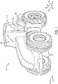
- FIG. 1 is a perspective view of an exemplary work vehicle 10 (e.g., tractor) that includes a wire routing system 12 that facilitates coupling a power supply supported within a frame 14 (e.g., fixed support structure) of the work vehicle 10 to an electrical component 16 (e.g., electric locks, window wipers, power windows, lights, alarms, or the like) supported by a door 18 of the work vehicle 10.
- the door 18 may be configured to move relative to the frame 14 of the work vehicle 10 to enable an operator to access and/or exit from a cabin 20 (e.g., operator cabin or cab) where the operator may sit or stand to operate the work vehicle 10.
- the work vehicle 10 includes wheels 22 that rotate to move the work vehicle 10.
- the wheels 22 may be replaced with tracks or other drive systems.
- the work vehicle 10 and the components therein may be described with reference to a lateral axis or direction 24, a longitudinal axis or direction 26, a vertical axis or direction 28, and a forward direction 30 (e.g., forward direction of travel).
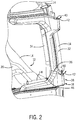
- FIG. 2 is a perspective view of a portion of the door 18 and the wire routing system 12.
- the frame 14 surrounds and/or defines the cabin 20 and may include one or more trim panels 32 (e.g., molded trim panels, interior trim panels, exterior trim panels) that are visible to the operator.
- the door 18 includes a door frame 34 (e.g., rigid support structure) configured to support an exterior door panel 36 (e.g., molded door panel) that may be visible to the operator.
- the door 18 is configured to move relative to the frame 14 between an open position to enable the operator to enter the cabin 20 and the illustrated closed position 38 to block access to the cabin 20 and/or to enclose the operator within the cabin 20.
- the door 18 is pivotally coupled to the frame 14 via one or more hinges 40 (e.g., pivots), which may be positioned laterally outwardly of the frame 14, the door frame 34, and/or the cabin 20.
- the door 18 may move from the closed position 38 to an open position via rotation about the one or more hinges 40, as shown by arrow 42.
- the wire routing system 12 includes a hollow member 44 (e.g., annular or cylindrical tube, conduit, pipe, or tubular support member) that is configured to receive and/or to support a coil cord.
- the hollow member 44 is part of the door frame 34, and thus, may contact, be coupled to, and/or structurally support interior and/or exterior door panels (e.g., the exterior door panel 36), window panes of the door 18, or the like.
- the hollow member 44 may be physically separate and distinct from the door frame 34 and may be coupled to the door frame 34 and/or supported by another component of the door 18 in a manner that enables the hollow member 44 to move with the door 18.
- the hollow member 44 may be positioned laterally inwardly of the one or more hinges 40 and/or the exterior door panel 36.
- the hollow member 44 is coupled to the exterior door panel 36 via a support bracket 46.
- FIG. 3 is a side view of the wire routing system 12.
- the hollow member 44 supports a coil cord 50 (e.g., coil wire, a retractable and/or extendable cord having electrically conductive wires supported within an insulating sheath) extending between a power supply 52 (e.g., battery) supported within the frame 14 and/or fixed relative to the frame 14, and an electrical component 54 supported by the door 18 and/or fixed relative to the door 18.
- a coil cord 50 e.g., coil wire, a retractable and/or extendable cord having electrically conductive wires supported within an insulating sheath
- a power supply 52 e.g., battery
- the electrical component 54 includes a door lock assembly having a lock that is configured to be electrically actuated (e.g., via a solenoid, magnet, motor, or the like) to move between a locked position to block movement of the door 18 relative to the frame 14 and an unlocked position to enable movement of the door 18 relative to the frame 14.
- the electrical component 54 may be any suitable electrically-actuated components, such as window wipers, power windows, lights, alarms, or the like.
- the coil cord 50 may extend from a first end portion 56 to a second end portion 58.
- the first end portion 56 is coupled to the power supply 52 and is positioned within the frame 14 and/or is fixed relative to the frame 14 of the work vehicle 10, while the second end portion 58 is coupled to the electrical component 54 within the door 18 and/or is fixed relative to the door 18.
- the coil cord 50 may extend from the power supply 52, through an opening 60 formed in the trim panel 32, and through the hollow member 44 to the electrical component 54.
- the electrical component 54 is positioned forward of and vertically below the opening 60 formed in the trim panel 32.
- the coil cord 50 and the hollow member 44 extend generally in the longitudinal direction 26 and the vertical direction 28 between the opening 60 formed in the trim panel 32 and the electrical component 54.
- the coil cord 50 includes one or more coiled portions 70 (e.g., looped portions) and one or more straight portions 72 (e.g., non-looped portions).
- the coiled portion 70 may extend only along a portion of a length (e.g., total length between the first end portion 56 and the second end portion 58) of the coil cord 50 (e.g., less than 2, 3, 4, 5, 10, 14, 25, or 50 percent of the length of the coil cord 50 or between about 2 to 50, 3 to 25, or 5 to 10 percent of the length of the coil cord 50) when the coil cord 50 is in illustrated fully retracted position (e.g., fully compressed position or resting position).
- the coiled portion 70 of the coil cord 50 is positioned within the hollow member 44, a first straight portion 72, 74 extends from the coiled portion 70 to the power supply 52 (e.g., across a gap 78 between the hollow member 44 and the opening 60 in the trim panel 32), and a second straight portion 72, 76 extends from the coiled portion 70 to the electrical component 54.
- an entirety of the coiled portion 70 is disposed within the hollow member 44 (i.e., the coiled portion 70 does not extend from the hollow member 44, does not extend across the gap 78, and/or is not visible from inside the cabin 20) when the door 18 is in the closed position 38 and/or when the door 18 is in the open position.
- the coiled portion 70 is positioned within a longitudinally-extending portion 80 of the hollow member 44.
- the longitudinally-extending portion 80 of the hollow member 44 includes an opening 82 at a first end 84 proximate to the opening 60 in the trim panel 32 to enable the coil cord 50 to connect to the power supply 52.
- the longitudinally-extending portion 80 is coupled to a vertically-extending portion 86 (e.g., rearward portion) of the door frame 34 and a generally curving or bending portion 88 of the door frame 34.
- the hollow member 44 and/or the door frame 34 may have any of a variety of shapes and configurations suitable to support components of the door 18 and/or to facilitate passage of the coil cord 50.
- the coil cord 50 is not attached to or fixed within the hollow member 44 so that the coil cord is free to move within the hollow member.
- the coil cord 50 is supported at the first end portion 56 via attachment to the power supply 52, at the second end portion 58 via attachment to the electrical component 54, and at the opening 60 of the trim panel 32 of the frame 14 via a strain relief device, such as a grommet, a bushing, an annular sleeve, a snap-on strain relief housing, or the like.
- the strain relief device may dimensionally control the position of the coil cord 50 relative to the trim panel 32.
- the strain relief device may be positioned such that the coil cord 50 is in some tension even while the door 18 is in the closed position 38 (i.e., the coil cord 50 is in the illustrated retracted position 90 [e.g., partially retracted position] and is not in a fully retracted or compressed state while the door 18 is in the closed position 38) so that the first straight portion 72, 74 of the coil cord 50 that extends across the gap 78 does not bend and/or is protected as the door 18 moves between the closed position 38 and the open position.
- the coil cord 50 may be configured to move from the illustrated retracted position 90 when the door 18 is in the closed position 38 to an extended position (e.g., expanded position) when the door 18 is in the open position.
- the coiled portion 70 and the coil cord 50 may increase in length as the door 18 moves from the closed position 38 to the open position, and the coil cord 50 may retract to the retracted position 90 as the door 18 moves from the open position to the closed position 38.
- a length 92 of the coiled portion 70 may increase by greater than or equal to approximately 1, 2, 3, 4, 5, 10, 15, 20, 25, or 50 percent
- a length of the coil cord 50 extending between the opening 60 in the trim panel 32 and the electrical component 54 may increase by greater than or equal to approximately 1, 2, 3, 4, 5, 10, 15, 20, or 25 percent.
- Such a configuration may reduce stress on the coil cord 50 as the door 18 moves from the closed position 38 to the open position and/or may block the door 18 from pinching the coil cord 50 as the door 18 moves from the open position to the closed position 38, for example.
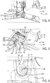
- FIG. 4 a perspective side view of an embodiment of a grommet 100 (e.g., a strain relief device, an annular ring, or a c-shaped ring) that may be positioned within the opening 60 formed in the trim panel 32 of the frame 14,
- FIG. 5 is a perspective top view of the grommet 100 supported within the opening 60 formed in the trim panel 32 of the frame 14, and
- FIG. 6 is a perspective view of the grommet 100.
- the grommet 100 may be configured to receive and to support the coil cord 50, such as the first straight portion 72, 74 of the coil cord 50 that extends from the opening 82 at the first end 84 of the longitudinally-extending portion 80 of the hollow member 44.
- the grommet 100 may be configured to clasp or clamp about the coil cord 50 (e.g., via an interference or friction fit) to block movement of the coil cord 50 through the grommet 100.
- the coil cord 50 does not move or slide through the grommet 100 as the door 18 moves between the closed position 38 and the open position.
- the grommet 100 includes a groove 102 (e.g., annular or c-shaped groove) that is formed in a radially-outer surface (e.g., annular surface) of the grommet 100 and that extends about a circumference of the grommet 100.
- the groove 102 may enable the grommet 100 to be slideably inserted into engagement with the trim panel 32.
- the groove 102 is disposed between radially-expanded portions 104 of the grommet 102.
- the radially-expanded portions 104 engage the frame 14 to retain the grommet 100 within the frame 14.
- the grommet 100 is a c-shaped ring or split ring, which may facilitate placement of the grommet 100 about the coil cord 50.
- the grommet 100 includes the groove 102, the radially-expanded portions 104, and an opening 108 that receives the coil cord 50, and the grommet 100 is positioned within the recess 106 of the frame 14 (e.g., the trim panel 32 of the frame 14).
- the grommet 100 as a physically separate structure that is configured to receive the coil cord 50 to facilitate discussion, it should be understood that any of a variety of configurations and/or strain relief devices may be utilized to hold or fix the coil cord 50 at the opening 60 formed in the trim panel 32 of the work vehicle 10 to block movement of the coil cord 50 through the opening 60), thereby providing strain relief and/or dimensionally controlling the position of the coil cord 50 relative to the trim panel 32.
- a bushing, an annular sleeve, and/or a snap-on strain relief housing may be provided about and/or coupled to the coil cord 50 (e.g., via an interference or friction fit) and attached to the work vehicle 10 (e.g., via fasteners, such as bolts, an interference fit, a key-slot interface, or the like).
- the grommet 100 or other strain relief device may be integrally formed with the coil cord 50, thus forming a one-piece coil cord 50 having the strain relief device or feature.
- FIG. 7 illustrates a coil cord assembly 110 having an integral grommet 112 molded onto and integrally formed with the coil cord 50.
- the illustrated grommet 112 includes two radially-extending portions 114 (e.g., annular protrusions) that define or are separated from one another by a groove 116 (e.g., annular or c-shaped groove) that is configured to receive or fit within the recess 106 of the frame 14 (e.g., the trim panel 32 of the frame 14).
- a groove 116 e.g., annular or c-shaped groove
- the coil cord assembly 110 is manufactured (e.g., via a molding process) and then installed as a unit into the work vehicle 10 (e.g., the grommet 112 portion is inserted into the recess 106 shown in FIGS. 5 and 6 ) to secure the coil cord 50 to the trim panel 32 of the work vehicle 10.
- an adhesive may be utilized to couple the grommet 100, 112 to the frame 14.
- the strain relief devices disclosed herein may be attached (e.g., snapped) into place about the coil cord 50 or molded on the coil cord 50 (e.g., forming a coil cord assembly having the strain relief device or feature).
- the grommet 100, 112 or other strain relief device may be positioned along the coil cord 50 such that the coil cord 50 is in some tension even while the door 18 is in the closed position 38 so that the portion of the coil cord 50 that extends across the gap 78 does not bend, thereby protecting the coil cord 50 and/or enabling movement of the door 18.
- the strain relief devices may enable repeatable and/or accurate installation of the coil cord 50 into the work vehicle 10, thereby facilitating efficient manufacturing of the work vehicle 10 and/or providing a configuration that protects the coil cord 50 during operation of the door 18.
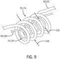
- FIG. 8 is a side view of an embodiment of a wire routing system 120 having multiple coil cords 50 that may be used in the work vehicle 10.
- a first coil cord 50, 122 includes a respective coil portion 70, 124 having a first diameter 126
- a second coil cord 50, 128 includes a respective coil portion 70, 130 having a second diameter 132, less than the first diameter 126.
- the respective coil portion 70, 130 of the second coil cord 50, 128 is positioned within the respective coil portion 70, 124 of the first coil cord 50, 122.
- FIG. 9 illustrates a perspective view of the respective coil portion 70, 130 of the second coil cord 50, 128 positioned within the respective coil portion 70, 124 of the first coil cord 50, 122.
- both the first coil cord 50, 122 and the second coil cord 50, 128 may lengthen (e.g., move from respective retracted positions to extended positions) simultaneously as the door 18 moves from the closed position 38 to the open position.
- Such a configuration may enable the use of multiple electrical components 54 within the door 18.
- the first coil cord 50, 122 couples the power supply 52 to a first electrical component 54, 134
- the second coil cord 50, 128 couples the power supply 52 to a second electrical component 54, 136.
- any suitable number of coil cords 50 e.g., 1, 2, 3, 4, 5, or more
- first coil cord 50, 122 and/or the second coil cord 50, 128 may have any of the features described above with respect to FIGS. 1-7 .
- the coil cords 50 may be supported within the longitudinally-extending portion 80 of the hollow member 44 and/or may not be attached to any portion of the hollow member 44.
- each coil cord may extend through and be supported by a respective strain relief device, such as a grommet 100, that engages the trim panel 32.
Landscapes
- Engineering & Computer Science (AREA)
- Mechanical Engineering (AREA)
- Architecture (AREA)
- Civil Engineering (AREA)
- Structural Engineering (AREA)
- Power-Operated Mechanisms For Wings (AREA)
- Electric Cable Arrangement Between Relatively Moving Parts (AREA)
- Installation Of Indoor Wiring (AREA)
Abstract
Description
- The present application relates generally to work vehicles, and more particularly, to a wire routing system for a work vehicle.
- Generally, work vehicles (e.g., tractors, harvesters, trucks, skid steers, or other prime movers) may be operated at worksites (e.g., agricultural fields or contstruction sites). Such work vehicles may include movable components, such as a door of a cab that facilitates ingress and egress of an operator. For example, the door may be movably coupled to the cab, and the door may move between an open position that enables the operator to enter the cab and a closed position that blocks access to the cab and/or that encloses the operator within the cab during operation of the work vehicle. In certain work vehicles, movement of the door between the open position and the closed position may limit the use of and/or interfere with wires (e.g., electrical wires) that extend between a fixed frame of the cab and a panel of the door.
- Certain embodiments commensurate in scope with the present disclosure are summarized below.
- A first embodiment includes a wire routing system for use in a work vehicle. The wire routing system includes a tubular support member coupled to a door of the work vehicle and a coil wire configured to conduct current from a power supply within the work vehicle to an electrical component supported by the door. A coiled portion of the coil wire is configured to be disposed within the tubular support member and to transition from a retracted position when the door is in a closed position to an extended position when the door is in an open position
- A second embodiment includes a system for use within a work vehicle. The system includes an electrical component configured to be supported by a movable component of the work vehicle and a coil wire configured to extend between and electrically couple the electrical component to a power supply supported within a frame of the work vehicle. The coil wire includes a coiled portion that is configured to be supported within a tubular support member coupled to the movable component and that is configured to transition from a retracted position when the movable component is in a first position to an extended position when the movable component is in a second position.
- A third embodiment includes a work vehicle having a vehicle frame defining an operator cabin and supporting a power supply, a door having a tubular support member and supporting an electrical component, and a coil wire that extends from the power supply and through the tubular support member to the electrical component, wherein a coiled portion of the coil wire is configured to transition from a retracted position when the door is in a closed position to an extended position when the door is in an open position.
- These and other features, aspects, and advantages of the present disclosure will become better understood when the following detailed description is read with reference to the accompanying drawings in which like characters represent like parts throughout the drawings, wherein:
-
FIG. 1 is a perspective side view of a work vehicle that includes a door and a wire routing system, in accordance with an embodiment of the present disclosure; -
FIG. 2 is a perspective side view of a portion of the door and the wire routing system ofFIG. 1 , in accordance with an embodiment of the present disclosure; -
FIG. 3 is a side view of the wire routing system ofFIG. 1 , in accordance with an embodiment of the present disclosure; -
FIG. 4 a perspective side view of a strain relief device and a hollow member of the wire routing system ofFIG. 1 , in accordance with an embodiment of the present disclosure; -
FIG. 5 is a perspective top view of the strain relief device and the hollow member ofFIG. 4 , in accordance with an embodiment of the present disclosure; -
FIG. 6 is a perspective front view of the strain relief device ofFIG. 4 , in accordance with an embodiment of the present disclosure; -
FIG. 7 illustrates a coil cord assembly having a strain relief device that may be used in the wire routing system ofFIG. 1 , in accordance with an embodiment of the present disclosure. -
FIG. 8 is a side view of a wire routing system having multiple coiled wires that may be used in the work vehicle ofFIG. 1 , in accordance with an embodiment of the present disclosure; and -
FIG. 9 is a perspective view of the multiple coiled wires ofFIG. 8 , in accordance with an embodiment of the present disclosure. - One or more specific embodiments of the present disclosure will be described below.
- When introducing elements of various embodiments of the present disclosure, the articles "a," "an," "the," and "said" are intended to mean that there are one or more of the elements. The terms "comprising," "including," and "having" are intended to be inclusive and mean that there may be additional elements other than the listed elements. Any examples of operating parameters and/or environmental conditions are not exclusive of other parameters/conditions of the disclosed embodiments.
- The embodiments disclosed herein relate generally to wire routing systems for work vehicles (e.g., tractors, harvesters, trucks, skid steers, or other prime movers). Certain work vehicles may include movable components, such as a door that is movably coupled to a cabin and that facilitates ingress and egress of an operator. In some work vehicles, it may be desirable to attach or include various electrical components within the door (e.g., electric locks, window wipers, power windows, lights, alarms, or the like). The wire routing systems disclosed herein may include a coil cord (e.g., a retractable and/or extendable cord having conductive wires) configured to extend from a power supply supported in a fixed position relative to a frame of the work vehicle to an electrical component supported by the door of the work vehicle. In some embodiments, a coiled portion (e.g., looped portion) of the coil cord may be supported within a hollow member (e.g., annular or cylindrical tube, conduit, or pipe) of the door, and a straight portion of the coil cord may extend from an end of the hollow member and through a strain relief device (e.g., a grommet, a bushing, an annular sleeve, a snap-on strain relief housing, or the like) supported within the frame of the work vehicle. The disclosed embodiments may provide a compact, simple, and/or low-cost wire routing system that may be efficiently installed into the work vehicle. Certain components of the wire routing system may support the coil cord and/or protect the coil cord from damage as the door moves between an open position and a closed position, thereby facilitating use of various electrical components within the door.
- To facilitate discussion, certain examples in the present disclosure are described in relation to a tractor. However, it should be appreciated that the embodiments and techniques described herein are not limited to tractors, and the wire routing system may be implemented in any suitable type of work vehicle, such as harvesters, trucks, and skid steers, for example. Moreover, certain examples in the present disclosure are described in relation to components supported by a door of a work vehicle. However, it should be understood that the wire routing systems may be utilized with components located in any movable structure (e.g., hood) of the work vehicle. Furthermore, certain examples in the present disclosure are described in relation to electrical cables and components. However, it should be appreciated that the embodiments and techniques described herein may be adapted to include hydraulic or pneumatic conduits and components, for example.
- With the foregoing in mind,
FIG. 1 is a perspective view of an exemplary work vehicle 10 (e.g., tractor) that includes awire routing system 12 that facilitates coupling a power supply supported within a frame 14 (e.g., fixed support structure) of thework vehicle 10 to an electrical component 16 (e.g., electric locks, window wipers, power windows, lights, alarms, or the like) supported by adoor 18 of thework vehicle 10. Thedoor 18 may be configured to move relative to theframe 14 of thework vehicle 10 to enable an operator to access and/or exit from a cabin 20 (e.g., operator cabin or cab) where the operator may sit or stand to operate thework vehicle 10. As shown, thework vehicle 10 includeswheels 22 that rotate to move thework vehicle 10. However, it should be understood that in some vehicles, thewheels 22 may be replaced with tracks or other drive systems. Thework vehicle 10 and the components therein may be described with reference to a lateral axis ordirection 24, a longitudinal axis ordirection 26, a vertical axis ordirection 28, and a forward direction 30 (e.g., forward direction of travel). -
FIG. 2 is a perspective view of a portion of thedoor 18 and thewire routing system 12. As shown, theframe 14 surrounds and/or defines thecabin 20 and may include one or more trim panels 32 (e.g., molded trim panels, interior trim panels, exterior trim panels) that are visible to the operator. In the illustrated embodiment, thedoor 18 includes a door frame 34 (e.g., rigid support structure) configured to support an exterior door panel 36 (e.g., molded door panel) that may be visible to the operator. Thedoor 18 is configured to move relative to theframe 14 between an open position to enable the operator to enter thecabin 20 and the illustrated closedposition 38 to block access to thecabin 20 and/or to enclose the operator within thecabin 20. In the illustrated embodiment, thedoor 18 is pivotally coupled to theframe 14 via one or more hinges 40 (e.g., pivots), which may be positioned laterally outwardly of theframe 14, thedoor frame 34, and/or thecabin 20. Thedoor 18 may move from the closedposition 38 to an open position via rotation about the one ormore hinges 40, as shown byarrow 42. - As discussed in more detail below, the
wire routing system 12 includes a hollow member 44 (e.g., annular or cylindrical tube, conduit, pipe, or tubular support member) that is configured to receive and/or to support a coil cord. In the illustrated embodiment, thehollow member 44 is part of thedoor frame 34, and thus, may contact, be coupled to, and/or structurally support interior and/or exterior door panels (e.g., the exterior door panel 36), window panes of thedoor 18, or the like. However, it should be understood that thehollow member 44 may be physically separate and distinct from thedoor frame 34 and may be coupled to thedoor frame 34 and/or supported by another component of thedoor 18 in a manner that enables thehollow member 44 to move with thedoor 18. As shown, thehollow member 44 may be positioned laterally inwardly of the one ormore hinges 40 and/or theexterior door panel 36. In the illustrated embodiment, thehollow member 44 is coupled to theexterior door panel 36 via asupport bracket 46. -
FIG. 3 is a side view of thewire routing system 12. As shown, thehollow member 44 supports a coil cord 50 (e.g., coil wire, a retractable and/or extendable cord having electrically conductive wires supported within an insulating sheath) extending between a power supply 52 (e.g., battery) supported within theframe 14 and/or fixed relative to theframe 14, and anelectrical component 54 supported by thedoor 18 and/or fixed relative to thedoor 18. In the illustrated embodiment, theelectrical component 54 includes a door lock assembly having a lock that is configured to be electrically actuated (e.g., via a solenoid, magnet, motor, or the like) to move between a locked position to block movement of thedoor 18 relative to theframe 14 and an unlocked position to enable movement of thedoor 18 relative to theframe 14. However, it should be understood that theelectrical component 54 may be any suitable electrically-actuated components, such as window wipers, power windows, lights, alarms, or the like. - The
coil cord 50 may extend from afirst end portion 56 to asecond end portion 58. As shown, thefirst end portion 56 is coupled to thepower supply 52 and is positioned within theframe 14 and/or is fixed relative to theframe 14 of thework vehicle 10, while thesecond end portion 58 is coupled to theelectrical component 54 within thedoor 18 and/or is fixed relative to thedoor 18. As discussed in more detail below, thecoil cord 50 may extend from thepower supply 52, through anopening 60 formed in thetrim panel 32, and through thehollow member 44 to theelectrical component 54. In the illustrated embodiment, theelectrical component 54 is positioned forward of and vertically below theopening 60 formed in thetrim panel 32. Thus, thecoil cord 50 and thehollow member 44 extend generally in thelongitudinal direction 26 and thevertical direction 28 between the opening 60 formed in thetrim panel 32 and theelectrical component 54. - In certain embodiments, the
coil cord 50 includes one or more coiled portions 70 (e.g., looped portions) and one or more straight portions 72 (e.g., non-looped portions). In some embodiments, the coiledportion 70 may extend only along a portion of a length (e.g., total length between thefirst end portion 56 and the second end portion 58) of the coil cord 50 (e.g., less than 2, 3, 4, 5, 10, 14, 25, or 50 percent of the length of thecoil cord 50 or between about 2 to 50, 3 to 25, or 5 to 10 percent of the length of the coil cord 50) when thecoil cord 50 is in illustrated fully retracted position (e.g., fully compressed position or resting position). In some embodiments, the coiledportion 70 of thecoil cord 50 is positioned within thehollow member 44, a first straight portion 72, 74 extends from the coiledportion 70 to the power supply 52 (e.g., across agap 78 between thehollow member 44 and theopening 60 in the trim panel 32), and a second straight portion 72, 76 extends from the coiledportion 70 to theelectrical component 54. In the illustrated embodiment, an entirety of the coiledportion 70 is disposed within the hollow member 44 (i.e., the coiledportion 70 does not extend from thehollow member 44, does not extend across thegap 78, and/or is not visible from inside the cabin 20) when thedoor 18 is in theclosed position 38 and/or when thedoor 18 is in the open position. - In the illustrated embodiment, the coiled
portion 70 is positioned within a longitudinally-extendingportion 80 of thehollow member 44. The longitudinally-extendingportion 80 of thehollow member 44 includes anopening 82 at afirst end 84 proximate to theopening 60 in thetrim panel 32 to enable thecoil cord 50 to connect to thepower supply 52. In the illustrated embodiment, the longitudinally-extendingportion 80 is coupled to a vertically-extending portion 86 (e.g., rearward portion) of thedoor frame 34 and a generally curving or bendingportion 88 of thedoor frame 34. However, it should be understood that thehollow member 44 and/or thedoor frame 34 may have any of a variety of shapes and configurations suitable to support components of thedoor 18 and/or to facilitate passage of thecoil cord 50. - In certain embodiments, the
coil cord 50 is not attached to or fixed within thehollow member 44 so that the coil cord is free to move within the hollow member. In some embodiments, thecoil cord 50 is supported at thefirst end portion 56 via attachment to thepower supply 52, at thesecond end portion 58 via attachment to theelectrical component 54, and at theopening 60 of thetrim panel 32 of theframe 14 via a strain relief device, such as a grommet, a bushing, an annular sleeve, a snap-on strain relief housing, or the like. As discussed in more detail below, the strain relief device may dimensionally control the position of thecoil cord 50 relative to thetrim panel 32. In some embodiments, the strain relief device may be positioned such that thecoil cord 50 is in some tension even while thedoor 18 is in the closed position 38 (i.e., thecoil cord 50 is in the illustrated retracted position 90 [e.g., partially retracted position] and is not in a fully retracted or compressed state while thedoor 18 is in the closed position 38) so that the first straight portion 72, 74 of thecoil cord 50 that extends across thegap 78 does not bend and/or is protected as thedoor 18 moves between theclosed position 38 and the open position. In operation, thecoil cord 50 may be configured to move from the illustrated retractedposition 90 when thedoor 18 is in theclosed position 38 to an extended position (e.g., expanded position) when thedoor 18 is in the open position. Thus, the coiledportion 70 and thecoil cord 50 may increase in length as thedoor 18 moves from theclosed position 38 to the open position, and thecoil cord 50 may retract to the retractedposition 90 as thedoor 18 moves from the open position to theclosed position 38. For example, alength 92 of the coiledportion 70 may increase by greater than or equal to approximately 1, 2, 3, 4, 5, 10, 15, 20, 25, or 50 percent, and/or a length of thecoil cord 50 extending between the opening 60 in thetrim panel 32 and theelectrical component 54 may increase by greater than or equal to approximately 1, 2, 3, 4, 5, 10, 15, 20, or 25 percent. Such a configuration may reduce stress on thecoil cord 50 as thedoor 18 moves from theclosed position 38 to the open position and/or may block thedoor 18 from pinching thecoil cord 50 as thedoor 18 moves from the open position to theclosed position 38, for example. -
FIG. 4 a perspective side view of an embodiment of a grommet 100 (e.g., a strain relief device, an annular ring, or a c-shaped ring) that may be positioned within theopening 60 formed in thetrim panel 32 of theframe 14,FIG. 5 is a perspective top view of thegrommet 100 supported within theopening 60 formed in thetrim panel 32 of theframe 14, andFIG. 6 is a perspective view of thegrommet 100. Thegrommet 100 may be configured to receive and to support thecoil cord 50, such as the first straight portion 72, 74 of thecoil cord 50 that extends from theopening 82 at thefirst end 84 of the longitudinally-extendingportion 80 of thehollow member 44. In some embodiments, thegrommet 100 may be configured to clasp or clamp about the coil cord 50 (e.g., via an interference or friction fit) to block movement of thecoil cord 50 through thegrommet 100. Thus, thecoil cord 50 does not move or slide through thegrommet 100 as thedoor 18 moves between theclosed position 38 and the open position. - As shown in
FIG. 5 , thegrommet 100 includes a groove 102 (e.g., annular or c-shaped groove) that is formed in a radially-outer surface (e.g., annular surface) of thegrommet 100 and that extends about a circumference of thegrommet 100. Thegroove 102 may enable thegrommet 100 to be slideably inserted into engagement with thetrim panel 32. In the illustrated embodiment, thegroove 102 is disposed between radially-expandedportions 104 of thegrommet 102. Thus, when thegrommet 100 is inserted into a recess 106 (e.g., corresponding groove) formed in the frame 14 (e.g., thetrim panel 32 of the frame 14), the radially-expandedportions 104 engage theframe 14 to retain thegrommet 100 within theframe 14. - As shown in
FIG. 6 , thegrommet 100 is a c-shaped ring or split ring, which may facilitate placement of thegrommet 100 about thecoil cord 50. Thegrommet 100 includes thegroove 102, the radially-expandedportions 104, and anopening 108 that receives thecoil cord 50, and thegrommet 100 is positioned within therecess 106 of the frame 14 (e.g., thetrim panel 32 of the frame 14). While the illustrated embodiments show thegrommet 100 as a physically separate structure that is configured to receive thecoil cord 50 to facilitate discussion, it should be understood that any of a variety of configurations and/or strain relief devices may be utilized to hold or fix thecoil cord 50 at theopening 60 formed in thetrim panel 32 of thework vehicle 10 to block movement of thecoil cord 50 through the opening 60), thereby providing strain relief and/or dimensionally controlling the position of thecoil cord 50 relative to thetrim panel 32. For example, a bushing, an annular sleeve, and/or a snap-on strain relief housing may be provided about and/or coupled to the coil cord 50 (e.g., via an interference or friction fit) and attached to the work vehicle 10 (e.g., via fasteners, such as bolts, an interference fit, a key-slot interface, or the like). In some embodiments, thegrommet 100 or other strain relief device may be integrally formed with thecoil cord 50, thus forming a one-piece coil cord 50 having the strain relief device or feature. For example,FIG. 7 illustrates acoil cord assembly 110 having anintegral grommet 112 molded onto and integrally formed with thecoil cord 50. The illustratedgrommet 112 includes two radially-extending portions 114 (e.g., annular protrusions) that define or are separated from one another by a groove 116 (e.g., annular or c-shaped groove) that is configured to receive or fit within therecess 106 of the frame 14 (e.g., thetrim panel 32 of the frame 14). When thegroove 116 of thegrommet 112 is inserted into therecess 106 formed in theframe 14, the radially-expandedportions 114 engage theframe 14 to hold thecoil cord 50 at theframe 14. In some embodiments, thecoil cord assembly 110 is manufactured (e.g., via a molding process) and then installed as a unit into the work vehicle 10 (e.g., thegrommet 112 portion is inserted into therecess 106 shown inFIGS. 5 and 6 ) to secure thecoil cord 50 to thetrim panel 32 of thework vehicle 10. In some embodiments, an adhesive may be utilized to couple thegrommet frame 14. - It should be appreciated that the strain relief devices disclosed herein may be attached (e.g., snapped) into place about the
coil cord 50 or molded on the coil cord 50 (e.g., forming a coil cord assembly having the strain relief device or feature). As noted above, in some embodiments, thegrommet coil cord 50 such that thecoil cord 50 is in some tension even while thedoor 18 is in theclosed position 38 so that the portion of thecoil cord 50 that extends across thegap 78 does not bend, thereby protecting thecoil cord 50 and/or enabling movement of thedoor 18. The strain relief devices may enable repeatable and/or accurate installation of thecoil cord 50 into thework vehicle 10, thereby facilitating efficient manufacturing of thework vehicle 10 and/or providing a configuration that protects thecoil cord 50 during operation of thedoor 18. -
FIG. 8 is a side view of an embodiment of awire routing system 120 havingmultiple coil cords 50 that may be used in thework vehicle 10. In the illustrated embodiment, afirst coil cord 50, 122 includes arespective coil portion 70, 124 having afirst diameter 126, and asecond coil cord 50, 128 includes arespective coil portion 70, 130 having asecond diameter 132, less than thefirst diameter 126. As shown, therespective coil portion 70, 130 of thesecond coil cord 50, 128 is positioned within therespective coil portion 70, 124 of thefirst coil cord 50, 122. For clarity,FIG. 9 illustrates a perspective view of therespective coil portion 70, 130 of thesecond coil cord 50, 128 positioned within therespective coil portion 70, 124 of thefirst coil cord 50, 122. - In operation, both the
first coil cord 50, 122 and thesecond coil cord 50, 128 may lengthen (e.g., move from respective retracted positions to extended positions) simultaneously as thedoor 18 moves from theclosed position 38 to the open position. Such a configuration may enable the use of multipleelectrical components 54 within thedoor 18. For example, thefirst coil cord 50, 122 couples thepower supply 52 to a firstelectrical component 54, 134, and thesecond coil cord 50, 128 couples thepower supply 52 to a secondelectrical component 54, 136. It should be understood that in certain embodiments, any suitable number of coil cords 50 (e.g., 1, 2, 3, 4, 5, or more) may extend through thehollow member 44 and/or may be positioned such that the respectivecoiled portions 70 are positioned within one another. Furthermore, thefirst coil cord 50, 122 and/or thesecond coil cord 50, 128 may have any of the features described above with respect toFIGS. 1-7 . For example, thecoil cords 50 may be supported within the longitudinally-extendingportion 80 of thehollow member 44 and/or may not be attached to any portion of thehollow member 44. For example, in some embodiments, each coil cord may extend through and be supported by a respective strain relief device, such as agrommet 100, that engages thetrim panel 32.
Claims (15)
- A wire routing system (12) for a work vehicle (10), comprising:a hollow member (44) coupled to a door (18) of the work vehicle (10); anda coil wire (50) configured to conduct current from a power supply (52) within the work vehicle (10) to an electrical component (54) supported by the door (18), wherein a coiled portion (70) of the coil wire (50) is configured to be disposed within the hollow member (44) and to transition from a retracted position when the door (18) is in a closed position to an extended position when the door is in an open position.
- The system of claim 1, wherein an entirety of the coiled portion (70) is disposed within the hollow member (44) when the door (18) is in the closed position and in the open position.
- The system of claims 1 or 2, wherein a straight portion (72) of the coil wire (50) extends from an end of the hollow member and through an opening in a frame of the work vehicle to reach the power supply.
- The system of any claim from 1 to 3, comprising a strain relief device (100), wherein the strain relief device (100) comprises an opening (108) configured to receive the coil wire (50), and the strain relief device (100) is configured to engage a frame (14) of the work vehicle (10) to attach the coil wire (50) to the frame (14) of the work vehicle (10).
- The system of claim 4, wherein the strain relief device (100) and the coil wire (50) are coupled to one another via an interference fit that blocks the coil wire (50) from sliding through the opening (108) of the strain relief device (100) as the door (18) moves between the closed position and the open position.
- The system of claims 1 or 2, comprising a strain relief device (112) that is integrally formed with the coil wire (50).
- The system of any claim from 4 to 6, wherein the strain relief device (100, 112) comprises a grommet (100, 112) comprising a groove (102, 116) formed in a radially-outer annular wall of the grommet (100, 112) that enables the grommet (100, 112) to slide into a corresponding recess (106) of the frame (14) of the work vehicle (10), and the grommet (100, 112) comprises radially-expanded portions (104, 114) that engage the frame (14) of the work vehicle (10) to block movement of the grommet (100, 112) relative to the frame (14) of the work vehicle (10).
- The system of any claim from 1 to 7, wherein the coil wire (50) is free to move within the hollow member (44).
- The system of any claim from 1 to 8, comprising the electrical component (54), wherein the electrical component (54) comprises one of a door lock or a window wiper.
- The system of claim 9, wherein the electrical component (54) comprises a door lock.
- The system of claim 9 or 10, wherein the electrical component (54) comprises a window wiper.
- The system of any claim from 1 to 11, wherein the power supply (52) is supported by a frame (14) of the work vehicle (10).
- The system of any claim from 1 to 12, wherein the coil wire (50) is in tension while the door (18) is in the closed position such that a portion (72,74) of the coil wire (50) that extends across a gap (78) between the hollow member (44) and the door (18) does not bend while the door (18) is in the closed position.
- The system of any claim from 1 to 13, comprising another coil wire (50, 128) configured to conduct current from the power supply (52) within the work vehicle (10) to another electrical component (54, 136) supported by the door (18), wherein a respective coiled portion (70, 130) of the another coil wire (50, 128) is configured to be disposed within the hollow member (44) and within the coiled portion (70) of the coil wire (50), and the respective coiled portion (70, 130) of the another coil wire (50, 128) is configured to transition from a respective retracted position when the door (18) is in the closed position to a respective extended position when the door (18) is in the open position.
- The system of claim 14, wherein the another electrical component (54, 136) comprises one of a door lock or a window wiper.
Applications Claiming Priority (1)
| Application Number | Priority Date | Filing Date | Title |
|---|---|---|---|
| US15/492,793 US20180304830A1 (en) | 2017-04-20 | 2017-04-20 | Wire routing system for a work vehicle |
Publications (2)
| Publication Number | Publication Date |
|---|---|
| EP3392089A1 true EP3392089A1 (en) | 2018-10-24 |
| EP3392089B1 EP3392089B1 (en) | 2020-02-19 |
Family
ID=62148092
Family Applications (1)
| Application Number | Title | Priority Date | Filing Date |
|---|---|---|---|
| EP18167636.2A Active EP3392089B1 (en) | 2017-04-20 | 2018-04-17 | Wire routing system for the door of a work vehicle |
Country Status (3)
| Country | Link |
|---|---|
| US (1) | US20180304830A1 (en) |
| EP (1) | EP3392089B1 (en) |
| CN (1) | CN108725344A (en) |
Cited By (1)
| Publication number | Priority date | Publication date | Assignee | Title |
|---|---|---|---|---|
| CN116979438A (en) * | 2023-09-20 | 2023-10-31 | 江苏迈道通信科技有限公司 | A feeder card with self-tightening function |
Families Citing this family (3)
| Publication number | Priority date | Publication date | Assignee | Title |
|---|---|---|---|---|
| KR20230096454A (en) * | 2021-12-23 | 2023-06-30 | 현대자동차주식회사 | Wire assembly for an anti-pinch sensor of vehicle |
| CN217690368U (en) * | 2022-04-15 | 2022-10-28 | 北京百度网讯科技有限公司 | Frame and vehicle |
| JP7803232B2 (en) * | 2022-09-01 | 2026-01-21 | 井関農機株式会社 | Work vehicles |
Citations (5)
| Publication number | Priority date | Publication date | Assignee | Title |
|---|---|---|---|---|
| JPH06278460A (en) * | 1993-03-24 | 1994-10-04 | Nissan Shatai Co Ltd | Harness arranging structure of door opening and closing part |
| JP2000232717A (en) * | 1999-02-12 | 2000-08-22 | Sumitomo Wiring Syst Ltd | Wiring harness wiring structure to glass hatch in car back door |
| JP2001138834A (en) * | 1999-11-15 | 2001-05-22 | Yazaki Corp | Cable routing structure of door opening / closing part |
| JP2001145244A (en) * | 1999-11-12 | 2001-05-25 | Yazaki Corp | Wired wire harness winding method and winding device |
| JP2003297475A (en) * | 2002-03-29 | 2003-10-17 | Yazaki Corp | Wire excess length absorption device and power supply device for slide door using the same |
Family Cites Families (12)
| Publication number | Priority date | Publication date | Assignee | Title |
|---|---|---|---|---|
| GB9526025D0 (en) * | 1995-12-20 | 1996-02-21 | Allen Group Ltd | Services-connections for trailer-vehicles |
| JP4036135B2 (en) * | 2003-04-18 | 2008-01-23 | 住友電装株式会社 | Grommet |
| DE102004048809A1 (en) * | 2004-10-07 | 2006-04-13 | Adam Opel Ag | Cable guide with cable channel especially for a retractable load carrier for a motor vehicle is telescopic and has at least one inner and outer tube |
| JP4355366B2 (en) * | 2005-11-10 | 2009-10-28 | 日産自動車株式会社 | High-voltage harness wiring structure for vehicles |
| JP4791251B2 (en) * | 2006-05-19 | 2011-10-12 | 矢崎総業株式会社 | Harness wiring structure of swinging part |
| CH703358A2 (en) * | 2010-06-25 | 2011-12-30 | Roger Vonwyl | Cable conduit pipe for electrical cable that is utilized for electrical installation in building construction sector, has pulling rope running within pipe part, where rope is longer than lengthwise section of pipe part |
| JP2012111406A (en) * | 2010-11-26 | 2012-06-14 | Sumitomo Wiring Syst Ltd | Wire harness cable routing structure, and protector |
| EP2680382B1 (en) * | 2012-06-27 | 2015-05-06 | OSRAM GmbH | Method for passing an electrical cable through a hole and device for same |
| JP6009257B2 (en) * | 2012-07-20 | 2016-10-19 | 矢崎総業株式会社 | Power supply structure for sliding door |
| JP6024041B2 (en) * | 2012-10-31 | 2016-11-09 | 矢崎総業株式会社 | Wire harness |
| JP6189241B2 (en) * | 2014-03-26 | 2017-08-30 | 株式会社クボタ | Working machine |
| CN106004715A (en) * | 2016-07-15 | 2016-10-12 | 广州市众科电器有限公司 | Wiring harness transitional sealing component between car body and car door |
-
2017
- 2017-04-20 US US15/492,793 patent/US20180304830A1/en not_active Abandoned
-
2018
- 2018-04-17 EP EP18167636.2A patent/EP3392089B1/en active Active
- 2018-04-20 CN CN201810365139.4A patent/CN108725344A/en active Pending
Patent Citations (5)
| Publication number | Priority date | Publication date | Assignee | Title |
|---|---|---|---|---|
| JPH06278460A (en) * | 1993-03-24 | 1994-10-04 | Nissan Shatai Co Ltd | Harness arranging structure of door opening and closing part |
| JP2000232717A (en) * | 1999-02-12 | 2000-08-22 | Sumitomo Wiring Syst Ltd | Wiring harness wiring structure to glass hatch in car back door |
| JP2001145244A (en) * | 1999-11-12 | 2001-05-25 | Yazaki Corp | Wired wire harness winding method and winding device |
| JP2001138834A (en) * | 1999-11-15 | 2001-05-22 | Yazaki Corp | Cable routing structure of door opening / closing part |
| JP2003297475A (en) * | 2002-03-29 | 2003-10-17 | Yazaki Corp | Wire excess length absorption device and power supply device for slide door using the same |
Cited By (2)
| Publication number | Priority date | Publication date | Assignee | Title |
|---|---|---|---|---|
| CN116979438A (en) * | 2023-09-20 | 2023-10-31 | 江苏迈道通信科技有限公司 | A feeder card with self-tightening function |
| CN116979438B (en) * | 2023-09-20 | 2023-12-15 | 江苏迈道通信科技有限公司 | Feeder line card with self-tightening function |
Also Published As
| Publication number | Publication date |
|---|---|
| BR102018007968A2 (en) | 2018-11-06 |
| CN108725344A (en) | 2018-11-02 |
| US20180304830A1 (en) | 2018-10-25 |
| EP3392089B1 (en) | 2020-02-19 |
Similar Documents
| Publication | Publication Date | Title |
|---|---|---|
| EP3392089B1 (en) | Wire routing system for the door of a work vehicle | |
| US7659480B2 (en) | Vehicle grommet | |
| EP3031643B1 (en) | Sliding window for vehicle, and trim board fixing method | |
| US6844497B2 (en) | Wire harness arrangement | |
| US9776538B1 (en) | Armrest hinge with cable pass-through | |
| US8746904B2 (en) | Seal and exterior rear view mirror assembly | |
| US12312848B2 (en) | Window regulator with optimized motor configuration | |
| US20220213729A1 (en) | Dual window regulator with optimized motor configuration | |
| EP1302350B1 (en) | Sunroof assembly with bus bar molded into sunroof frame and corresponding assembly method | |
| EP3031644B1 (en) | Vehicle slide window and power supply device | |
| US11878734B2 (en) | Roof assembly for a work vehicle | |
| US6053554A (en) | Multi-section vertically retractable and extendable tail gate system | |
| EP1707443B1 (en) | Power supply apparatus for sliding door | |
| CN107521312B (en) | Drive device for a sun protection device | |
| US20230279713A1 (en) | Window regulator for a frameless system | |
| JP2021121140A (en) | Cable assembly | |
| JP6907510B2 (en) | How to install harnesses on vehicle doors and vehicle doors | |
| CN224082949U (en) | Emergency power generation car access box | |
| KR100655620B1 (en) | Wiring clip member | |
| CN219770025U (en) | Intelligent traction trolley | |
| CN224256586U (en) | Vehicle door harness mounting structure and vehicle applying same | |
| KR0136955Y1 (en) | Automobile door glass holder and carrier plate combined structure | |
| CN218172235U (en) | Electric lifting rod and automobile auxiliary braking device | |
| CN107963152B (en) | A multi-point locking system for electric vehicles | |
| CN212953629U (en) | Automobile door wire harness with telescopic structure |
Legal Events
| Date | Code | Title | Description |
|---|---|---|---|
| PUAI | Public reference made under article 153(3) epc to a published international application that has entered the european phase |
Free format text: ORIGINAL CODE: 0009012 |
|
| STAA | Information on the status of an ep patent application or granted ep patent |
Free format text: STATUS: THE APPLICATION HAS BEEN PUBLISHED |
|
| AK | Designated contracting states |
Kind code of ref document: A1 Designated state(s): AL AT BE BG CH CY CZ DE DK EE ES FI FR GB GR HR HU IE IS IT LI LT LU LV MC MK MT NL NO PL PT RO RS SE SI SK SM TR |
|
| AX | Request for extension of the european patent |
Extension state: BA ME |
|
| STAA | Information on the status of an ep patent application or granted ep patent |
Free format text: STATUS: REQUEST FOR EXAMINATION WAS MADE |
|
| 17P | Request for examination filed |
Effective date: 20190424 |
|
| RBV | Designated contracting states (corrected) |
Designated state(s): AL AT BE BG CH CY CZ DE DK EE ES FI FR GB GR HR HU IE IS IT LI LT LU LV MC MK MT NL NO PL PT RO RS SE SI SK SM TR |
|
| RIC1 | Information provided on ipc code assigned before grant |
Ipc: B60R 16/02 20060101AFI20190618BHEP Ipc: B60J 5/04 20060101ALI20190618BHEP |
|
| GRAP | Despatch of communication of intention to grant a patent |
Free format text: ORIGINAL CODE: EPIDOSNIGR1 |
|
| STAA | Information on the status of an ep patent application or granted ep patent |
Free format text: STATUS: GRANT OF PATENT IS INTENDED |
|
| INTG | Intention to grant announced |
Effective date: 20190906 |
|
| GRAS | Grant fee paid |
Free format text: ORIGINAL CODE: EPIDOSNIGR3 |
|
| GRAA | (expected) grant |
Free format text: ORIGINAL CODE: 0009210 |
|
| STAA | Information on the status of an ep patent application or granted ep patent |
Free format text: STATUS: THE PATENT HAS BEEN GRANTED |
|
| AK | Designated contracting states |
Kind code of ref document: B1 Designated state(s): AL AT BE BG CH CY CZ DE DK EE ES FI FR GB GR HR HU IE IS IT LI LT LU LV MC MK MT NL NO PL PT RO RS SE SI SK SM TR |
|
| REG | Reference to a national code |
Ref country code: CH Ref legal event code: EP |
|
| REG | Reference to a national code |
Ref country code: DE Ref legal event code: R096 Ref document number: 602018002471 Country of ref document: DE |
|
| REG | Reference to a national code |
Ref country code: AT Ref legal event code: REF Ref document number: 1234599 Country of ref document: AT Kind code of ref document: T Effective date: 20200315 |
|
| REG | Reference to a national code |
Ref country code: IE Ref legal event code: FG4D |
|
| REG | Reference to a national code |
Ref country code: NL Ref legal event code: MP Effective date: 20200219 |
|
| PG25 | Lapsed in a contracting state [announced via postgrant information from national office to epo] |
Ref country code: FI Free format text: LAPSE BECAUSE OF FAILURE TO SUBMIT A TRANSLATION OF THE DESCRIPTION OR TO PAY THE FEE WITHIN THE PRESCRIBED TIME-LIMIT Effective date: 20200219 Ref country code: NO Free format text: LAPSE BECAUSE OF FAILURE TO SUBMIT A TRANSLATION OF THE DESCRIPTION OR TO PAY THE FEE WITHIN THE PRESCRIBED TIME-LIMIT Effective date: 20200519 Ref country code: RS Free format text: LAPSE BECAUSE OF FAILURE TO SUBMIT A TRANSLATION OF THE DESCRIPTION OR TO PAY THE FEE WITHIN THE PRESCRIBED TIME-LIMIT Effective date: 20200219 |
|
| REG | Reference to a national code |
Ref country code: LT Ref legal event code: MG4D |
|
| PG25 | Lapsed in a contracting state [announced via postgrant information from national office to epo] |
Ref country code: HR Free format text: LAPSE BECAUSE OF FAILURE TO SUBMIT A TRANSLATION OF THE DESCRIPTION OR TO PAY THE FEE WITHIN THE PRESCRIBED TIME-LIMIT Effective date: 20200219 Ref country code: LV Free format text: LAPSE BECAUSE OF FAILURE TO SUBMIT A TRANSLATION OF THE DESCRIPTION OR TO PAY THE FEE WITHIN THE PRESCRIBED TIME-LIMIT Effective date: 20200219 Ref country code: SE Free format text: LAPSE BECAUSE OF FAILURE TO SUBMIT A TRANSLATION OF THE DESCRIPTION OR TO PAY THE FEE WITHIN THE PRESCRIBED TIME-LIMIT Effective date: 20200219 Ref country code: GR Free format text: LAPSE BECAUSE OF FAILURE TO SUBMIT A TRANSLATION OF THE DESCRIPTION OR TO PAY THE FEE WITHIN THE PRESCRIBED TIME-LIMIT Effective date: 20200520 Ref country code: IS Free format text: LAPSE BECAUSE OF FAILURE TO SUBMIT A TRANSLATION OF THE DESCRIPTION OR TO PAY THE FEE WITHIN THE PRESCRIBED TIME-LIMIT Effective date: 20200619 Ref country code: BG Free format text: LAPSE BECAUSE OF FAILURE TO SUBMIT A TRANSLATION OF THE DESCRIPTION OR TO PAY THE FEE WITHIN THE PRESCRIBED TIME-LIMIT Effective date: 20200519 |
|
| PG25 | Lapsed in a contracting state [announced via postgrant information from national office to epo] |
Ref country code: NL Free format text: LAPSE BECAUSE OF FAILURE TO SUBMIT A TRANSLATION OF THE DESCRIPTION OR TO PAY THE FEE WITHIN THE PRESCRIBED TIME-LIMIT Effective date: 20200219 |
|
| PG25 | Lapsed in a contracting state [announced via postgrant information from national office to epo] |
Ref country code: ES Free format text: LAPSE BECAUSE OF FAILURE TO SUBMIT A TRANSLATION OF THE DESCRIPTION OR TO PAY THE FEE WITHIN THE PRESCRIBED TIME-LIMIT Effective date: 20200219 Ref country code: CZ Free format text: LAPSE BECAUSE OF FAILURE TO SUBMIT A TRANSLATION OF THE DESCRIPTION OR TO PAY THE FEE WITHIN THE PRESCRIBED TIME-LIMIT Effective date: 20200219 Ref country code: RO Free format text: LAPSE BECAUSE OF FAILURE TO SUBMIT A TRANSLATION OF THE DESCRIPTION OR TO PAY THE FEE WITHIN THE PRESCRIBED TIME-LIMIT Effective date: 20200219 Ref country code: DK Free format text: LAPSE BECAUSE OF FAILURE TO SUBMIT A TRANSLATION OF THE DESCRIPTION OR TO PAY THE FEE WITHIN THE PRESCRIBED TIME-LIMIT Effective date: 20200219 Ref country code: LT Free format text: LAPSE BECAUSE OF FAILURE TO SUBMIT A TRANSLATION OF THE DESCRIPTION OR TO PAY THE FEE WITHIN THE PRESCRIBED TIME-LIMIT Effective date: 20200219 Ref country code: SM Free format text: LAPSE BECAUSE OF FAILURE TO SUBMIT A TRANSLATION OF THE DESCRIPTION OR TO PAY THE FEE WITHIN THE PRESCRIBED TIME-LIMIT Effective date: 20200219 Ref country code: EE Free format text: LAPSE BECAUSE OF FAILURE TO SUBMIT A TRANSLATION OF THE DESCRIPTION OR TO PAY THE FEE WITHIN THE PRESCRIBED TIME-LIMIT Effective date: 20200219 Ref country code: PT Free format text: LAPSE BECAUSE OF FAILURE TO SUBMIT A TRANSLATION OF THE DESCRIPTION OR TO PAY THE FEE WITHIN THE PRESCRIBED TIME-LIMIT Effective date: 20200712 Ref country code: SK Free format text: LAPSE BECAUSE OF FAILURE TO SUBMIT A TRANSLATION OF THE DESCRIPTION OR TO PAY THE FEE WITHIN THE PRESCRIBED TIME-LIMIT Effective date: 20200219 |
|
| REG | Reference to a national code |
Ref country code: AT Ref legal event code: MK05 Ref document number: 1234599 Country of ref document: AT Kind code of ref document: T Effective date: 20200219 |
|
| REG | Reference to a national code |
Ref country code: DE Ref legal event code: R097 Ref document number: 602018002471 Country of ref document: DE |
|
| PG25 | Lapsed in a contracting state [announced via postgrant information from national office to epo] |
Ref country code: MC Free format text: LAPSE BECAUSE OF FAILURE TO SUBMIT A TRANSLATION OF THE DESCRIPTION OR TO PAY THE FEE WITHIN THE PRESCRIBED TIME-LIMIT Effective date: 20200219 |
|
| PLBE | No opposition filed within time limit |
Free format text: ORIGINAL CODE: 0009261 |
|
| STAA | Information on the status of an ep patent application or granted ep patent |
Free format text: STATUS: NO OPPOSITION FILED WITHIN TIME LIMIT |
|
| 26N | No opposition filed |
Effective date: 20201120 |
|
| PG25 | Lapsed in a contracting state [announced via postgrant information from national office to epo] |
Ref country code: AT Free format text: LAPSE BECAUSE OF FAILURE TO SUBMIT A TRANSLATION OF THE DESCRIPTION OR TO PAY THE FEE WITHIN THE PRESCRIBED TIME-LIMIT Effective date: 20200219 Ref country code: LU Free format text: LAPSE BECAUSE OF NON-PAYMENT OF DUE FEES Effective date: 20200417 |
|
| REG | Reference to a national code |
Ref country code: BE Ref legal event code: MM Effective date: 20200430 |
|
| PG25 | Lapsed in a contracting state [announced via postgrant information from national office to epo] |
Ref country code: BE Free format text: LAPSE BECAUSE OF NON-PAYMENT OF DUE FEES Effective date: 20200430 Ref country code: PL Free format text: LAPSE BECAUSE OF FAILURE TO SUBMIT A TRANSLATION OF THE DESCRIPTION OR TO PAY THE FEE WITHIN THE PRESCRIBED TIME-LIMIT Effective date: 20200219 Ref country code: SI Free format text: LAPSE BECAUSE OF FAILURE TO SUBMIT A TRANSLATION OF THE DESCRIPTION OR TO PAY THE FEE WITHIN THE PRESCRIBED TIME-LIMIT Effective date: 20200219 |
|
| PG25 | Lapsed in a contracting state [announced via postgrant information from national office to epo] |
Ref country code: IE Free format text: LAPSE BECAUSE OF NON-PAYMENT OF DUE FEES Effective date: 20200417 |
|
| PG25 | Lapsed in a contracting state [announced via postgrant information from national office to epo] |
Ref country code: CH Free format text: LAPSE BECAUSE OF NON-PAYMENT OF DUE FEES Effective date: 20210430 Ref country code: LI Free format text: LAPSE BECAUSE OF NON-PAYMENT OF DUE FEES Effective date: 20210430 |
|
| PG25 | Lapsed in a contracting state [announced via postgrant information from national office to epo] |
Ref country code: TR Free format text: LAPSE BECAUSE OF FAILURE TO SUBMIT A TRANSLATION OF THE DESCRIPTION OR TO PAY THE FEE WITHIN THE PRESCRIBED TIME-LIMIT Effective date: 20200219 Ref country code: MT Free format text: LAPSE BECAUSE OF FAILURE TO SUBMIT A TRANSLATION OF THE DESCRIPTION OR TO PAY THE FEE WITHIN THE PRESCRIBED TIME-LIMIT Effective date: 20200219 Ref country code: CY Free format text: LAPSE BECAUSE OF FAILURE TO SUBMIT A TRANSLATION OF THE DESCRIPTION OR TO PAY THE FEE WITHIN THE PRESCRIBED TIME-LIMIT Effective date: 20200219 |
|
| PG25 | Lapsed in a contracting state [announced via postgrant information from national office to epo] |
Ref country code: MK Free format text: LAPSE BECAUSE OF FAILURE TO SUBMIT A TRANSLATION OF THE DESCRIPTION OR TO PAY THE FEE WITHIN THE PRESCRIBED TIME-LIMIT Effective date: 20200219 Ref country code: AL Free format text: LAPSE BECAUSE OF FAILURE TO SUBMIT A TRANSLATION OF THE DESCRIPTION OR TO PAY THE FEE WITHIN THE PRESCRIBED TIME-LIMIT Effective date: 20200219 |
|
| PGFP | Annual fee paid to national office [announced via postgrant information from national office to epo] |
Ref country code: GB Payment date: 20260421 Year of fee payment: 9 |
|
| PGFP | Annual fee paid to national office [announced via postgrant information from national office to epo] |
Ref country code: IT Payment date: 20260422 Year of fee payment: 9 |
|
| PGFP | Annual fee paid to national office [announced via postgrant information from national office to epo] |
Ref country code: DE Payment date: 20260421 Year of fee payment: 9 |
|
| PGFP | Annual fee paid to national office [announced via postgrant information from national office to epo] |
Ref country code: FR Payment date: 20260423 Year of fee payment: 9 |