EP3391977A1 - Cooling device - Google Patents
Cooling device Download PDFInfo
- Publication number
- EP3391977A1 EP3391977A1 EP15910802.6A EP15910802A EP3391977A1 EP 3391977 A1 EP3391977 A1 EP 3391977A1 EP 15910802 A EP15910802 A EP 15910802A EP 3391977 A1 EP3391977 A1 EP 3391977A1
- Authority
- EP
- European Patent Office
- Prior art keywords
- accommodation space
- coolant
- spray
- cooling device
- tub
- Prior art date
- Legal status (The legal status is an assumption and is not a legal conclusion. Google has not performed a legal analysis and makes no representation as to the accuracy of the status listed.)
- Withdrawn
Links
- 238000001816 cooling Methods 0.000 title claims abstract description 85
- 239000007921 spray Substances 0.000 claims abstract description 114
- 239000002826 coolant Substances 0.000 claims abstract description 104
- 230000004308 accommodation Effects 0.000 claims abstract description 60
- 238000005507 spraying Methods 0.000 claims abstract description 3
- 238000009434 installation Methods 0.000 claims description 23
- 238000004891 communication Methods 0.000 claims description 5
- 230000000149 penetrating effect Effects 0.000 claims description 3
- 238000005096 rolling process Methods 0.000 description 28
- 238000000034 method Methods 0.000 description 23
- 238000005098 hot rolling Methods 0.000 description 10
- 238000004804 winding Methods 0.000 description 9
- 238000010438 heat treatment Methods 0.000 description 8
- 239000013077 target material Substances 0.000 description 8
- 230000003247 decreasing effect Effects 0.000 description 4
- 230000009466 transformation Effects 0.000 description 4
- 229910000831 Steel Inorganic materials 0.000 description 3
- 239000000463 material Substances 0.000 description 3
- 239000010959 steel Substances 0.000 description 3
- 230000015556 catabolic process Effects 0.000 description 2
- 230000007547 defect Effects 0.000 description 2
- 238000012423 maintenance Methods 0.000 description 2
- 230000004043 responsiveness Effects 0.000 description 2
- QVGXLLKOCUKJST-UHFFFAOYSA-N atomic oxygen Chemical compound [O] QVGXLLKOCUKJST-UHFFFAOYSA-N 0.000 description 1
- 230000000694 effects Effects 0.000 description 1
- 238000004519 manufacturing process Methods 0.000 description 1
- 229910052760 oxygen Inorganic materials 0.000 description 1
- 239000001301 oxygen Substances 0.000 description 1
- 238000000926 separation method Methods 0.000 description 1
- 239000000126 substance Substances 0.000 description 1
Images




Classifications
-
- B—PERFORMING OPERATIONS; TRANSPORTING
- B21—MECHANICAL METAL-WORKING WITHOUT ESSENTIALLY REMOVING MATERIAL; PUNCHING METAL
- B21B—ROLLING OF METAL
- B21B45/00—Devices for surface or other treatment of work, specially combined with or arranged in, or specially adapted for use in connection with, metal-rolling mills
- B21B45/02—Devices for surface or other treatment of work, specially combined with or arranged in, or specially adapted for use in connection with, metal-rolling mills for lubricating, cooling, or cleaning
- B21B45/0203—Cooling
- B21B45/0209—Cooling devices, e.g. using gaseous coolants
- B21B45/0215—Cooling devices, e.g. using gaseous coolants using liquid coolants, e.g. for sections, for tubes
- B21B45/0233—Spray nozzles, Nozzle headers; Spray systems
-
- B—PERFORMING OPERATIONS; TRANSPORTING
- B21—MECHANICAL METAL-WORKING WITHOUT ESSENTIALLY REMOVING MATERIAL; PUNCHING METAL
- B21B—ROLLING OF METAL
- B21B45/00—Devices for surface or other treatment of work, specially combined with or arranged in, or specially adapted for use in connection with, metal-rolling mills
- B21B45/02—Devices for surface or other treatment of work, specially combined with or arranged in, or specially adapted for use in connection with, metal-rolling mills for lubricating, cooling, or cleaning
- B21B45/0203—Cooling
- B21B45/0209—Cooling devices, e.g. using gaseous coolants
- B21B45/0215—Cooling devices, e.g. using gaseous coolants using liquid coolants, e.g. for sections, for tubes
- B21B45/0218—Cooling devices, e.g. using gaseous coolants using liquid coolants, e.g. for sections, for tubes for strips, sheets, or plates
-
- B—PERFORMING OPERATIONS; TRANSPORTING
- B21—MECHANICAL METAL-WORKING WITHOUT ESSENTIALLY REMOVING MATERIAL; PUNCHING METAL
- B21B—ROLLING OF METAL
- B21B2261/00—Product parameters
- B21B2261/20—Temperature
- B21B2261/21—Temperature profile
-
- B—PERFORMING OPERATIONS; TRANSPORTING
- B21—MECHANICAL METAL-WORKING WITHOUT ESSENTIALLY REMOVING MATERIAL; PUNCHING METAL
- B21B—ROLLING OF METAL
- B21B2263/00—Shape of product
- B21B2263/04—Flatness
- B21B2263/06—Edge waves
Definitions
- the present invention relates to a cooling device, and more particularly, to a cooling device which feeds a coolant to a predetermined width of a cooling target in accordance with a level of the coolant in a tub installed above the cooling target.
- a slab which is heated in a heating furnace to a predetermined temperature, is rolled in the form of a bar by a primary rough rolling and then finally rolled in the form of a strip by a finish rolling machine. While the strip passes through a run-out table including multiple rollers, a coolant is fed to the strip from above and below the strip to ensure a winding temperature, and then a winding machine winds the strip in the form of a roll to produce a hot coil.
- the run-out table performs a process of conveying a material, that is, the strip which has passed through the heating furnace and has subjected to the rough rolling and the finish rolling, before the winding machine finally winds the strip.
- This process cools the material to a target temperature to determine quality and strength of a product.
- the remaining coolant which has fallen to a central portion in a width direction of the strip, flows outward through edge portions of strip, such that a temperature at both edge portions typically becomes lower than a temperature at the central portion.
- the edge portions which are cooled or excessively cooled, shrink in volume first, and then the central portion, which is subsequently cooled, shrinks in volume. With this temperature deviation, there occurs a difference in timing of shrinkage in volume, which causes the strip to have a wave shape.
- the strip is cooled typically in a high-temperature state at a temperature of about 600 or more, and as a result, the strip expands in volume in a transformation section that occurs during the process of cooling the strip in accordance with types of steel.
- the expansion in volume occurs at the edge portions of the strip which are cooled before the central portion of the strip is cooled. Therefore, when the edge portions begin to be transformed in a predetermined section, the edge portions, which are cooled first, expand in volume, but the high-temperature central portion, which does not yet go into the transformation section, shrinks in volume while being cooled, and this process is a typical mechanism that causes the edge portions to have waves.
- the present invention has been made in an effort to prevent an edge wave generated during a process of cooling a cooling target to a winding temperature.
- the present invention has also been made in an effort to provide a cooling target cooling device capable of feeding a coolant with quick responsiveness and stability.
- An exemplary embodiment of the present invention provides a cooling device including: a tub which is disposed above a cooling target and has an accommodation space that accommodates a coolant supplied from the outside; and spray nozzles which are installed in the accommodation space, each of the spray nozzles having one or more outer inlet ports into which the coolant flows, the spray nozzles being disposed to be spaced apart from a central portion of the accommodation space toward an edge portion of the accommodation space, and the spray nozzles spraying the coolant, which flows in through the outer inlet port, toward the cooling target, in which heights of the outer inlet ports are in proportion to distances at which the spray nozzles are spaced apart from the central portion of the accommodation space.
- the tub may have a spray plate having multiple installation holes which are disposed to be spaced apart from one another while penetrating one surface facing the cooling target and each have internal screw threads formed on an inner circumferential surface thereof, and the spray nozzle may have an external screw thread which is formed on an outer circumferential surface of the spray nozzle and fastened to the internal screw thread of the installation hole by a threaded connection, such that a position of the spray nozzle is adjusted by a rotation of the spray nozzle.
- the spray nozzles may be arranged in a direction in parallel with a width direction of the cooling target.
- the spray nozzle may include: a nozzle body which has the external screw thread, is disposed to be approximately perpendicular to the spray plate, and has a spray flow path formed therein and a spray port formed at a lower end of the spray flow path; and a nozzle cap which is fastened to an upper portion of the nozzle body and has the multiple outer inlet ports.
- the nozzle cap may be fastened to the nozzle body by a threaded connection, such that a height of the outer inlet port is adjustable by a rotation of the nozzle cap.
- the spray plate may have auxiliary installation holes which are disposed to be spaced apart from one another while penetrating one surface facing the cooling target and positioned at a central portion of the accommodation space, and the cooling device may further include an auxiliary spray nozzle having auxiliary inlet ports which are in communication with the auxiliary installation holes and disposed to be lower than a height of the outer inlet port.
- the tub may include: an inner tub which has side plates disposed in parallel with a direction in which the spray nozzles are spaced apart from one another; and a supply pipe which supplies the coolant into the inner tub, and the side plate may have a central portion and an edge portion having an upper end higher than an upper end of the central portion.
- a height of the upper end of the edge portion may be gradually increased toward an edge portion of the accommodation space.
- the cooling device may further include meshes which are fixedly installed on an inner circumferential surface of the inner tub and disposed in parallel with a direction in which the spray nozzles are spaced apart from one another.
- the meshes may have an upper mesh and a lower mesh positioned below the upper mesh.
- the supply pipe may be installed at a center of the accommodation space, and the meshes may be disposed at both sides of the supply pipe and in contact with the supply pipe.
- the tub may include: an inner tub which has side plates disposed in parallel with a direction in which the accommodation space and the spray nozzles are spaced apart from one another; and an outer tub which is disposed outside the inner tub and surrounds the inner tub, and the spray plate may be disposed between the inner tub and the outer tub and disposed to be higher than a lower end of the inner tub and a lower end of the outer tub.
- the tub may further have an auxiliary accommodation space which is positioned between the inner tub and the outer tub and formed above the spray plate.
- a cooling device including: a tub which is disposed above a cooling target and has an accommodation space that accommodates a coolant supplied from the outside; and spray nozzles which are installed in the accommodation space and have outer inlet ports into which the coolant selectively flows in accordance with a level of the coolant, and spray ports through which the coolant is sprayed toward the cooling target.
- Heights of the outer inlet port may be gradually increased in a width direction of the cooling target.
- the tub may have an inner accommodation space into which the coolant is supplied, and an outer accommodation space into which the coolant overflowing from the inner accommodation space flows, and the spray nozzles may be installed in the outer accommodation space.
- the tub may have a side plate which defines the inner accommodation space and the outer accommodation space, and a height of a central portion of the side plate may be lower than heights of edge portions positioned at both sides of the central portion.
- a height of the side plate in the width direction of the cooling target may be higher than heights of the spray nozzles.
- the cooling device may further include: an auxiliary spray nozzle which is installed at a center of the accommodation space and has auxiliary inlet ports disposed to be lower than heights of the outer inlet ports, in which the spray nozzles are disposed at both sides of the auxiliary spray nozzle.
- the exemplary embodiment of the present invention it is possible to solve the problems of high installation costs, complicated structures and materials in use, and frequent breakdowns caused by poor working environments that occur in the cooling device using the edge mask in the related art, and as a result, it is possible to make it easy to manufacture the cooling device and improve stability and responsiveness when feeding the coolant. Therefore, it is possible to easily change the amount of coolant in the width direction, thereby preventing edge portions of a steel plate from being excessively cooled, and improving productivity and quality of final products.
- FIGS. 1 to 10 An exemplary embodiment of the present invention will be described in more detail with reference to FIGS. 1 to 10 .
- the exemplary embodiments of the present invention may be modified in various forms, and the scope of the present invention should not be interpreted as being limited to the following exemplary embodiment.
- the exemplary embodiments of the present invention are provided to more completely explain the present invention to those skilled in the art. Therefore, the shapes of the respective elements illustrated in the drawings may be exaggerated to emphasize a clearer description.
- FIG. 1 is a view schematically illustrating a general hot rolling apparatus.
- the hot rolling apparatus includes a heating furnace 11 which heats a slab 1, a rough rolling machine 12 which performs rough rolling on a rolling target material heated in the heating furnace 11, a finish rolling machine 13 which performs finish rolling on the rolling target material (e.g., a bar) which has been subjected to the rough rolling, a run-out table 14 which conveys the rolling target material (e.g., a strip) which has been subjected to the finish rolling, and a winding machine 15 which winds the conveyed rolling target material in the form of a coil.
- a heating furnace 11 which heats a slab 1
- a rough rolling machine 12 which performs rough rolling on a rolling target material heated in the heating furnace 11
- a finish rolling machine 13 which performs finish rolling on the rolling target material (e.g., a bar) which has been subjected to the rough rolling
- a run-out table 14 which conveys the rolling target material (e.g.
- the slab 1 sequentially passes through the heating furnace 11, the rough rolling machine 12, the finish rolling machine 13, the run-out table 14, and the winding machine 15, and then is wound in the form of a coil.
- the slab (or bar 1) which has been subjected to the rough rolling, travels to the finish rolling machine 13
- the rolling target material is subjected to the finish rolling while individually controlling rolling speeds of multiple rollers provided in the finish rolling machine 13.
- the process including all of the overall operations of heating the rolling target material 1 in the heating furnace 11 and then winding the rolling target material 1 in the form of a coil by the winding machine 15 is typically called "hot rolling".
- the run-out table 14 performs the process of conveying the rolling target material 1, that is, the strip 1, which has passed through the heating furnace 11 and has been subjected to the rough rolling and the finish rolling, before the winding machine 15 finally winds the strip 1, and in this process, the strip 1 is cooled to a target temperature to determine quality and strength of a product.
- a strip wave which is a shape defect caused by a cooling deviation in the width direction of the strip, is generated as a troublesome problem, and a generation mechanism is as follows.
- FIG. 2 is a view for explaining a cause that generates an edge wave during a cooling process.
- a coolant which has fallen at the central portion in the width direction of the strip 1, flows outward through the edge portions of the strip 1, such that a temperature at the edge portions of the strip 1 typically becomes lower than a temperature at the central portion thereof.
- the strip 1 is cooled typically in a high-temperature state at a temperature of about 600 or more, and as a result, the strip expands in volume in a transformation section that occurs during the process of cooling the strip in accordance with types of steel.
- this phenomenon occurs first at the edge portions of the strip 1 which are cooled before the central portion of the strip 1 is cooled. Therefore, when the edge portions begin to be transformed in a predetermined section, the edge portions, which are cooled first, expand in volume, but the high-temperature central portion, which does not yet go into the transformation section, shrinks in volume while being cooled. This phenomenon is a typical mechanism that causes the edge portions to have waves.
- FIG. 3 is a view illustrating a strip cooling device using an edge mask in the related art.
- the strip cooling device serves to prevent the edge portions from being excessively cooled. That is, to reduce the cooling deviation occurring in the width direction of the strip 1 while the strip 1 is cooled on the run-out table 14, edge mask devices 18 are mounted and operated at both end portions of a laminar bank 20.
- the edge masks 18 are installed to solve the problem that the coolant, which has fallen at the central portion in the width direction of the strip 1, flows outward through the edge portions of the strip 1 during the process of cooling the strip 1, such that the temperature at the edge portions is controlled to be lower than the temperature at the central portion, which causes the cooling deviation in the width direction.
- the edge masks 18 serve to prevent the coolant fed from the laminar bank 20 from being fed to both end portions of the strip 1, and positions of the edge masks 18 are automatically controlled to prevent the coolant from being fed to the edge portions of the hot rolling strip 1 having an overall width of maximum 300 mm, and maximum 150 mm at a single side.
- the aforementioned method of preventing the edge portion from being excessively cooled still has a problem of high costs required to install facilities and a problem of difficulty in maintenance of the facilities.
- power of a motor is transmitted to driving shafts of the edge masks 18 through chains, and the edge masks 18 are attached to the driving shafts and move in the width direction.
- the strip at a high temperature of 600°C or more typically moves in the section of the run-out table 14, such that moisture vapor is generated by the coolant and the generated moisture vapor carries scale generated by a reaction with oxygen in the atmosphere.
- the scale is formed on a motor unit which is corroded by being exposed to a high temperature, the driving shaft, and a bearing of a connecting unit that connects the driving shaft and the chain, which causes frequent breakdowns of the facilities due to an overload of the motor.
- a sensor which detects a position of the strip 1, does not smoothly detect the position of the strip 1 due to the generated high-temperature moisture vapor, and as a result, a defect frequently occurs when controlling the strip 1 in the width direction. Because the scale enters and adheres to the driving shaft and a chain connecting unit, and as a result, a large amount of time is required to remove the adhering scale at the time of maintaining the edge masks 18. Due to the difficulty in maintenance, the important function of preventing the edge portions from being excessively cooled is frequently incompletely performed.
- FIG. 4 is a view schematically illustrating a cooling device according to an exemplary embodiment of the present invention
- FIGS. 5 to 8 are views illustrating the cooling device illustrated in FIG. 4 .
- the cooling device is installed above the roller table 14 that conveys the strip 1 rolled by the finish rolling machine 13.
- the cooling device includes an inner tub 20 and an outer tub 30.
- the inner tub 20 has an inner accommodation space that may accommodate a coolant, and a supply pipe 35 is installed inside the inner accommodation space and supplies the coolant into the inner accommodation space.
- the supply pipe 35 is disposed approximately in parallel with the width direction of the strip 1.
- the supply pipe 35 has multiple supply holes 35a, and the coolant supplied from the outside is accommodated in the inner accommodation space through the supply holes 35a. Meanwhile, unlike the present exemplary embodiment, the supply pipe 35 may be installed outside the inner accommodation space and supply the coolant into the inner accommodation space.
- Mesh members are fixedly installed on an inner circumferential surface of the inner tub 20 and supported by an outer circumferential surface of the supply pipe 35.
- the mesh members include an upper mesh 62 and a lower mesh 64, and the mesh member has a quadrangular cylinder shape disposed approximately in parallel with the supply pipe 35.
- the outer tub 30 is installed outside the inner tub 20 and surrounds the inner tub 20, and a cover 31 closes an opened upper side of the outer tub 30 from the outside. As illustrated in FIG. 8 , a front side plate and a rear side plate of the outer tub 30 are spaced apart from a front side plate and a rear side plate of the inner tub 20.
- Spray plates 40 are installed between the front side plate of the inner tub 20 and the front side plate of the outer tub 30 and between the rear side plate of the inner tub 20 and the rear side plate of the outer tub 30, respectively, and as a result, outer accommodation spaces positioned outside the inner accommodation space are formed at upper portions of the spray plate 40, respectively.
- each of the front side plate and the rear side plate has an edge upper end 20a which is positioned above spray nozzles 50, and a central upper end 20b which is positioned above an auxiliary spray nozzle 60.
- the central upper end 20b is disposed horizontally, and the edge upper end 20a is disposed to be inclined upward from one end (or both ends) of the central upper end 20b.
- the spray plate 40 has multiple installation holes 41 and multiple auxiliary installation holes 42, and the spray plate 40 is disposed approximately in parallel with the width direction of the strip 1 and positioned above the strip 1.
- a central portion (or center) of the spray plate 40 corresponds to a central portion (or center) of the strip 1
- edge portions of the spray plate 40 correspond to the edge portions of the strip 1.
- the auxiliary installation holes 42 are formed at the central portion of the spray plate 40, and the installation holes 41 are formed at both sides based on the auxiliary installation holes 42 ( FIG. 5 illustrates only one side).
- the auxiliary installation hole 42 has a tapered shape having a cross-sectional area decreasing downward, and the installation hole 41 has a straight shape having a screw thread formed on an inner circumferential surface thereof.
- the spray nozzles 50 are installed on the installation holes 41 and disposed to be spaced apart from one another in the width direction of the strip 1. As illustrated in FIG. 6 , the spray nozzle 50 has a nozzle body 52 and a nozzle cap 54, the nozzle cap 54 is fastened to the nozzle body 52 by a threaded connection, and the nozzle body 52 is fastened to the installation hole 41 by a threaded connection.
- the nozzle cap 54 has one or more coolant inlet ports 54a which penetrate the nozzle cap 54 in a vertical direction, and the coolant inlet port 54a is in communication with a flow path 53 of the nozzle body 52 in a state in which the nozzle cap 54 is fastened to the nozzle body 52.
- the nozzle cap 54 has a screw thread formed on an inner circumferential surface thereof, and the nozzle cap 54 is fastened to an upper end portion 57 of the nozzle body 52 by a threaded connection.
- the nozzle body 52 has stepped portions formed as a diameter of the upper end portion 57 and a diameter of a lower end portion 55 are decreased.
- the nozzle body 52 has a screw thread formed on an outer circumferential surface of the upper end portion 57, and the nozzle body 52 is fastened to the screw thread of the nozzle cap 54 by a threaded connection.
- the nozzle body 52 has a screw thread formed on an outer circumferential surface of the lower end portion 55, and the nozzle body 52 is fastened to the screw thread formed on the inner circumferential surface of the installation hole 41 by a threaded connection. Therefore, it is possible to adjust a height of the spray nozzle 50 by rotating the nozzle body 52, and it is possible to adjust a height of the coolant inlet port 54a by rotating the nozzle cap 54.
- the nozzle body 52 has the flow path 53 formed in the nozzle body 52, and a spray port 53a formed at a lower end of the flow path 53, and the flow path 53 is in communication with the coolant inlet port 54a.
- An upper end of the flow path 53 has a tapered shape having a cross-sectional area increasing upward, such that the coolant may smoothly flow into the flow path 53 through the coolant inlet port 54a.
- the auxiliary spray nozzle 60 is installed on the auxiliary installation holes 42, and the auxiliary spray nozzle 60 has coolant inlet ports 62 which are in communication with the auxiliary installation holes 42.
- the auxiliary installation hole 42 has a tapered shape having a cross-sectional area increasing downward, such that the coolant may smoothly flow into the auxiliary installation hole 42 through the coolant inlet port 62.
- the spray nozzles 50 are installed at both sides based on the auxiliary spray nozzle 60 ( FIG. 5 illustrates only one side), and heights h1 to h6 of the upper ends of the spray nozzles 50 are increased in proportion to distances d at which the spray nozzles 50 are spaced apart from the auxiliary spray nozzle 60 (or the central portion of the inner accommodation space). Therefore, the heights h1 to h6 of the coolant inlet ports 54a are increased in proportion to a separation distance.
- a height h0 of the upper end of the auxiliary spray nozzle 60 is lower than the heights h1 to h6 of the upper ends of the spray nozzles 50.
- FIGS. 9 and 10 are views illustrating a state in which the cooling device illustrated in FIGS. 5 and 8 operates.
- a method of operating the cooling device will be described below with reference to FIGS. 9 and 10 .
- the coolant is supplied into the inner accommodation space of the cooling device (specifically, the inner tub 20) through the supply pipe 35.
- the coolant is supplied into the inner accommodation space through the supply holes 35a, and foreign substances may be filtered out by mesh holes 64a of the lower mesh 64 and mesh holes 62a of the upper mesh 62.
- a diameter of the mesh hole 64a may be larger than a diameter of the mesh hole 62a.
- the coolant flows into the outer accommodation space while flowing over the front side plate and the rear side plate of the inner tub 20. Thereafter, as illustrated in FIG. 9 , in accordance with a level of the coolant accommodated in the outer accommodation space, the coolant flows into the auxiliary spray nozzle 60 through the coolant inlet ports 62 and then is sprayed toward the strip 1, and the coolant flows into the spray nozzles 50 through the coolant inlet ports 54a and then is sprayed toward the strip 1.
- the coolant is sprayed first through the coolant inlet ports 62, and then the coolant is sprayed sequentially through the coolant inlet ports 54a in the order from the coolant inlet port 54a positioned at a lowest position to the coolant inlet port 54a positioned at a highest position. Therefore, when an operator intends to adjust a width of the coolant to be fed, the operator adjusts the level of the coolant in the outer accommodation space, such that whether the coolant is supplied into the spray nozzles 50 is determined based on the level of the coolant, and as a result, it is possible to adjust a cooling range for the strip 1.
- the spray plate 40 is installed to be higher than a lower end of the inner tub 20 and a lower end of the outer tub 30, and the coolant sprayed from the spray plate 40 is guided by a lower portion of the inner tub 20 and a lower portion of the outer tub 30 which protrude toward a lower portion of the spray plate 40, thereby preventing the coolant from being sprayed toward an unnecessary portion.
- FIGS. 11 to 13 exemplary embodiments of the present invention will be described in more detail with reference to FIGS. 11 to 13 .
- the exemplary embodiments of the present invention may be modified in various forms, and the scope of the present invention should not be interpreted as being limited to the following exemplary embodiment.
- the exemplary embodiments of the present invention are provided to more completely explain the present invention to those skilled in the art. Therefore, the shapes of the respective elements illustrated in the drawings may be exaggerated to emphasize a clearer description.
- FIGS. 11 and 12 are views illustrating a process of adjusting a height of the spray nozzle illustrated in FIG. 5 .
- a user may determine, for each spray nozzle 50, whether to spray the coolant through the spray nozzle 50 by rotating the nozzle cap 54 regardless of the level of the coolant (because an operation of adjusting the level of the coolant requires a large amount of time and affects all of the spray nozzles 50), and as a result, it is possible to spray the coolant asymmetrically based on the center of the strip 1.
- the present exemplary embodiment has described that the height of the coolant inlet port 54a is adjusted by rotating the nozzle cap 54 or the nozzle body 52, but the scope of the present invention is not limited thereto, and it is possible to adjust the height of the coolant inlet port 54a through another exemplary embodiment.
- the nozzle cap 54 or the nozzle body 52 may be rotated by a driving device such as a motor.
- FIG. 13 is a view illustrating a modified example of the cooling device illustrated in FIG. 5 .
- a coolant inlet port 52a may be formed at a lateral side of the spray nozzle 50.
- the spray nozzles 50 are installed at both sides based on the auxiliary spray nozzle 60 ( FIG. 5 illustrates only one side), and heights h1 to h6 of the coolant inlet ports 54a are increased in proportion to distances d at which the spray nozzles 50 are spaced apart from the auxiliary spray nozzle 60 (or the central portion of the inner accommodation space).
- the present invention may be applied to various types of cooling devices.
Landscapes
- Engineering & Computer Science (AREA)
- Mechanical Engineering (AREA)
- Heat Treatments In General, Especially Conveying And Cooling (AREA)
- Heat Treatment Of Strip Materials And Filament Materials (AREA)
- Nozzles (AREA)
Abstract
Description
- The present invention relates to a cooling device, and more particularly, to a cooling device which feeds a coolant to a predetermined width of a cooling target in accordance with a level of the coolant in a tub installed above the cooling target.
- In general, in a hot rolling process that produces a rolled strip, a slab, which is heated in a heating furnace to a predetermined temperature, is rolled in the form of a bar by a primary rough rolling and then finally rolled in the form of a strip by a finish rolling machine. While the strip passes through a run-out table including multiple rollers, a coolant is fed to the strip from above and below the strip to ensure a winding temperature, and then a winding machine winds the strip in the form of a roll to produce a hot coil.
- The run-out table performs a process of conveying a material, that is, the strip which has passed through the heating furnace and has subjected to the rough rolling and the finish rolling, before the winding machine finally winds the strip. This process cools the material to a target temperature to determine quality and strength of a product. During the process of cooling the strip, the remaining coolant, which has fallen to a central portion in a width direction of the strip, flows outward through edge portions of strip, such that a temperature at both edge portions typically becomes lower than a temperature at the central portion. In this process, the edge portions, which are cooled or excessively cooled, shrink in volume first, and then the central portion, which is subsequently cooled, shrinks in volume. With this temperature deviation, there occurs a difference in timing of shrinkage in volume, which causes the strip to have a wave shape.
- In particular, during the cooling process in the hot rolling process, the strip is cooled typically in a high-temperature state at a temperature of about 600 or more, and as a result, the strip expands in volume in a transformation section that occurs during the process of cooling the strip in accordance with types of steel. The expansion in volume occurs at the edge portions of the strip which are cooled before the central portion of the strip is cooled. Therefore, when the edge portions begin to be transformed in a predetermined section, the edge portions, which are cooled first, expand in volume, but the high-temperature central portion, which does not yet go into the transformation section, shrinks in volume while being cooled, and this process is a typical mechanism that causes the edge portions to have waves.
- The present invention has been made in an effort to prevent an edge wave generated during a process of cooling a cooling target to a winding temperature. The present invention has also been made in an effort to provide a cooling target cooling device capable of feeding a coolant with quick responsiveness and stability. Other objects of the present invention will be more apparent from the following detailed description and the drawings.
- An exemplary embodiment of the present invention provides a cooling device including: a tub which is disposed above a cooling target and has an accommodation space that accommodates a coolant supplied from the outside; and spray nozzles which are installed in the accommodation space, each of the spray nozzles having one or more outer inlet ports into which the coolant flows, the spray nozzles being disposed to be spaced apart from a central portion of the accommodation space toward an edge portion of the accommodation space, and the spray nozzles spraying the coolant, which flows in through the outer inlet port, toward the cooling target, in which heights of the outer inlet ports are in proportion to distances at which the spray nozzles are spaced apart from the central portion of the accommodation space.
- The tub may have a spray plate having multiple installation holes which are disposed to be spaced apart from one another while penetrating one surface facing the cooling target and each have internal screw threads formed on an inner circumferential surface thereof, and the spray nozzle may have an external screw thread which is formed on an outer circumferential surface of the spray nozzle and fastened to the internal screw thread of the installation hole by a threaded connection, such that a position of the spray nozzle is adjusted by a rotation of the spray nozzle.
- The spray nozzles may be arranged in a direction in parallel with a width direction of the cooling target.
- The spray nozzle may include: a nozzle body which has the external screw thread, is disposed to be approximately perpendicular to the spray plate, and has a spray flow path formed therein and a spray port formed at a lower end of the spray flow path; and a nozzle cap which is fastened to an upper portion of the nozzle body and has the multiple outer inlet ports.
- The nozzle cap may be fastened to the nozzle body by a threaded connection, such that a height of the outer inlet port is adjustable by a rotation of the nozzle cap.
- The spray plate may have auxiliary installation holes which are disposed to be spaced apart from one another while penetrating one surface facing the cooling target and positioned at a central portion of the accommodation space, and the cooling device may further include an auxiliary spray nozzle having auxiliary inlet ports which are in communication with the auxiliary installation holes and disposed to be lower than a height of the outer inlet port.
- The tub may include: an inner tub which has side plates disposed in parallel with a direction in which the spray nozzles are spaced apart from one another; and a supply pipe which supplies the coolant into the inner tub, and the side plate may have a central portion and an edge portion having an upper end higher than an upper end of the central portion.
- A height of the upper end of the edge portion may be gradually increased toward an edge portion of the accommodation space.
- The cooling device may further include meshes which are fixedly installed on an inner circumferential surface of the inner tub and disposed in parallel with a direction in which the spray nozzles are spaced apart from one another.
- The meshes may have an upper mesh and a lower mesh positioned below the upper mesh.
- The supply pipe may be installed at a center of the accommodation space, and the meshes may be disposed at both sides of the supply pipe and in contact with the supply pipe.
- The tub may include: an inner tub which has side plates disposed in parallel with a direction in which the accommodation space and the spray nozzles are spaced apart from one another; and an outer tub which is disposed outside the inner tub and surrounds the inner tub, and the spray plate may be disposed between the inner tub and the outer tub and disposed to be higher than a lower end of the inner tub and a lower end of the outer tub.
- The tub may further have an auxiliary accommodation space which is positioned between the inner tub and the outer tub and formed above the spray plate.
- Another exemplary embodiment of the present invention provides a cooling device including: a tub which is disposed above a cooling target and has an accommodation space that accommodates a coolant supplied from the outside; and spray nozzles which are installed in the accommodation space and have outer inlet ports into which the coolant selectively flows in accordance with a level of the coolant, and spray ports through which the coolant is sprayed toward the cooling target.
- Heights of the outer inlet port may be gradually increased in a width direction of the cooling target.
- The tub may have an inner accommodation space into which the coolant is supplied, and an outer accommodation space into which the coolant overflowing from the inner accommodation space flows, and the spray nozzles may be installed in the outer accommodation space.
- The tub may have a side plate which defines the inner accommodation space and the outer accommodation space, and a height of a central portion of the side plate may be lower than heights of edge portions positioned at both sides of the central portion.
- A height of the side plate in the width direction of the cooling target may be higher than heights of the spray nozzles.
- The cooling device may further include: an auxiliary spray nozzle which is installed at a center of the accommodation space and has auxiliary inlet ports disposed to be lower than heights of the outer inlet ports, in which the spray nozzles are disposed at both sides of the auxiliary spray nozzle.
- According to the exemplary embodiment of the present invention, it is possible to solve the problems of high installation costs, complicated structures and materials in use, and frequent breakdowns caused by poor working environments that occur in the cooling device using the edge mask in the related art, and as a result, it is possible to make it easy to manufacture the cooling device and improve stability and responsiveness when feeding the coolant. Therefore, it is possible to easily change the amount of coolant in the width direction, thereby preventing edge portions of a steel plate from being excessively cooled, and improving productivity and quality of final products.
-
-
FIG. 1 is a view schematically illustrating a general hot rolling apparatus. -
FIG. 2 is a view for explaining a cause that generates an edge wave during a cooling process. -
FIG. 3 is a view illustrating a cooling device using an edge mask. -
FIG. 4 is a view schematically illustrating a cooling device according to an exemplary embodiment of the present invention. -
FIGS. 5 to 8 are views illustrating the cooling device illustrated inFIG. 4 . -
FIGS. 9 and10 are views illustrating a state in which the cooling device illustrated inFIGS. 5 and8 operates. -
FIGS. 11 and12 are views illustrating a process of adjusting a height of a spray nozzle illustrated inFIG. 5 . -
FIG. 13 is a view illustrating a modified example of the cooling device illustrated inFIG. 5 . - Hereinafter, an exemplary embodiment of the present invention will be described in more detail with reference to
FIGS. 1 to 10 . The exemplary embodiments of the present invention may be modified in various forms, and the scope of the present invention should not be interpreted as being limited to the following exemplary embodiment. The exemplary embodiments of the present invention are provided to more completely explain the present invention to those skilled in the art. Therefore, the shapes of the respective elements illustrated in the drawings may be exaggerated to emphasize a clearer description. -
FIG. 1 is a view schematically illustrating a general hot rolling apparatus. As illustrated inFIG. 1 , the hot rolling apparatus includes aheating furnace 11 which heats aslab 1, arough rolling machine 12 which performs rough rolling on a rolling target material heated in theheating furnace 11, afinish rolling machine 13 which performs finish rolling on the rolling target material (e.g., a bar) which has been subjected to the rough rolling, a run-out table 14 which conveys the rolling target material (e.g., a strip) which has been subjected to the finish rolling, and awinding machine 15 which winds the conveyed rolling target material in the form of a coil. - The
slab 1 sequentially passes through theheating furnace 11, therough rolling machine 12, thefinish rolling machine 13, the run-out table 14, and thewinding machine 15, and then is wound in the form of a coil. When the slab (or bar 1), which has been subjected to the rough rolling, travels to thefinish rolling machine 13, the rolling target material is subjected to the finish rolling while individually controlling rolling speeds of multiple rollers provided in thefinish rolling machine 13. As described above, the process including all of the overall operations of heating therolling target material 1 in theheating furnace 11 and then winding therolling target material 1 in the form of a coil by thewinding machine 15 is typically called "hot rolling". - During the hot rolling process, the run-out table 14 performs the process of conveying the
rolling target material 1, that is, thestrip 1, which has passed through theheating furnace 11 and has been subjected to the rough rolling and the finish rolling, before thewinding machine 15 finally winds thestrip 1, and in this process, thestrip 1 is cooled to a target temperature to determine quality and strength of a product. In this case, a strip wave, which is a shape defect caused by a cooling deviation in the width direction of the strip, is generated as a troublesome problem, and a generation mechanism is as follows. -
FIG. 2 is a view for explaining a cause that generates an edge wave during a cooling process. As illustrated inFIG. 2 , during the process of cooling thestrip 1 by the run-out table 14, a coolant, which has fallen at the central portion in the width direction of thestrip 1, flows outward through the edge portions of thestrip 1, such that a temperature at the edge portions of thestrip 1 typically becomes lower than a temperature at the central portion thereof. - In this process, the edge portions of the
strip 1, which are cooled or excessively cooled, shrink in volume first, and then the central portion of thestrip 1, which is subsequently cooled, shrinks in volume. With this temperature deviation, there occurs a difference in timing of shrinkage in volume, which causes thestrip 1 to have a wave shape. - In particular, during the cooling process in the hot rolling process, the
strip 1 is cooled typically in a high-temperature state at a temperature of about 600 or more, and as a result, the strip expands in volume in a transformation section that occurs during the process of cooling the strip in accordance with types of steel. As described above, this phenomenon occurs first at the edge portions of thestrip 1 which are cooled before the central portion of thestrip 1 is cooled. Therefore, when the edge portions begin to be transformed in a predetermined section, the edge portions, which are cooled first, expand in volume, but the high-temperature central portion, which does not yet go into the transformation section, shrinks in volume while being cooled. This phenomenon is a typical mechanism that causes the edge portions to have waves. -
FIG. 3 is a view illustrating a strip cooling device using an edge mask in the related art. As illustrated inFIG. 3 , as a method in the related art which prevents the waves generated in the edge portions of thestrip 1, the strip cooling device serves to prevent the edge portions from being excessively cooled. That is, to reduce the cooling deviation occurring in the width direction of thestrip 1 while thestrip 1 is cooled on the run-out table 14,edge mask devices 18 are mounted and operated at both end portions of alaminar bank 20. - The edge masks 18 are installed to solve the problem that the coolant, which has fallen at the central portion in the width direction of the
strip 1, flows outward through the edge portions of thestrip 1 during the process of cooling thestrip 1, such that the temperature at the edge portions is controlled to be lower than the temperature at the central portion, which causes the cooling deviation in the width direction. The edge masks 18 serve to prevent the coolant fed from thelaminar bank 20 from being fed to both end portions of thestrip 1, and positions of the edge masks 18 are automatically controlled to prevent the coolant from being fed to the edge portions of thehot rolling strip 1 having an overall width of maximum 300 mm, and maximum 150 mm at a single side. - However, the aforementioned method of preventing the edge portion from being excessively cooled still has a problem of high costs required to install facilities and a problem of difficulty in maintenance of the facilities. In addition, power of a motor is transmitted to driving shafts of the edge masks 18 through chains, and the edge masks 18 are attached to the driving shafts and move in the width direction. In the hot rolling process, the strip at a high temperature of 600°C or more typically moves in the section of the run-out table 14, such that moisture vapor is generated by the coolant and the generated moisture vapor carries scale generated by a reaction with oxygen in the atmosphere. The scale is formed on a motor unit which is corroded by being exposed to a high temperature, the driving shaft, and a bearing of a connecting unit that connects the driving shaft and the chain, which causes frequent breakdowns of the facilities due to an overload of the motor.
- In addition, a sensor (not illustrated), which detects a position of the
strip 1, does not smoothly detect the position of thestrip 1 due to the generated high-temperature moisture vapor, and as a result, a defect frequently occurs when controlling thestrip 1 in the width direction. Because the scale enters and adheres to the driving shaft and a chain connecting unit, and as a result, a large amount of time is required to remove the adhering scale at the time of maintaining the edge masks 18. Due to the difficulty in maintenance, the important function of preventing the edge portions from being excessively cooled is frequently incompletely performed. -
FIG. 4 is a view schematically illustrating a cooling device according to an exemplary embodiment of the present invention, andFIGS. 5 to 8 are views illustrating the cooling device illustrated inFIG. 4 . The cooling device is installed above the roller table 14 that conveys thestrip 1 rolled by thefinish rolling machine 13. - As illustrated in
FIGS. 5 and8 , the cooling device includes aninner tub 20 and anouter tub 30. Theinner tub 20 has an inner accommodation space that may accommodate a coolant, and asupply pipe 35 is installed inside the inner accommodation space and supplies the coolant into the inner accommodation space. Thesupply pipe 35 is disposed approximately in parallel with the width direction of thestrip 1. Thesupply pipe 35 has multiple supply holes 35a, and the coolant supplied from the outside is accommodated in the inner accommodation space through the supply holes 35a. Meanwhile, unlike the present exemplary embodiment, thesupply pipe 35 may be installed outside the inner accommodation space and supply the coolant into the inner accommodation space. - Mesh members are fixedly installed on an inner circumferential surface of the
inner tub 20 and supported by an outer circumferential surface of thesupply pipe 35. The mesh members include anupper mesh 62 and alower mesh 64, and the mesh member has a quadrangular cylinder shape disposed approximately in parallel with thesupply pipe 35. - The
outer tub 30 is installed outside theinner tub 20 and surrounds theinner tub 20, and acover 31 closes an opened upper side of theouter tub 30 from the outside. As illustrated inFIG. 8 , a front side plate and a rear side plate of theouter tub 30 are spaced apart from a front side plate and a rear side plate of theinner tub 20. - Spray
plates 40 are installed between the front side plate of theinner tub 20 and the front side plate of theouter tub 30 and between the rear side plate of theinner tub 20 and the rear side plate of theouter tub 30, respectively, and as a result, outer accommodation spaces positioned outside the inner accommodation space are formed at upper portions of thespray plate 40, respectively. - The inner accommodation space and the outer accommodation spaces are divided by the front side plate and the rear side plate of the
inner tub 20, and as illustrated inFIG. 5 , each of the front side plate and the rear side plate has an edgeupper end 20a which is positioned abovespray nozzles 50, and a centralupper end 20b which is positioned above anauxiliary spray nozzle 60. In this case, the centralupper end 20b is disposed horizontally, and the edgeupper end 20a is disposed to be inclined upward from one end (or both ends) of the centralupper end 20b. - As illustrated in
FIG. 5 , thespray plate 40 has multiple installation holes 41 and multiple auxiliary installation holes 42, and thespray plate 40 is disposed approximately in parallel with the width direction of thestrip 1 and positioned above thestrip 1. In particular, a central portion (or center) of thespray plate 40 corresponds to a central portion (or center) of thestrip 1, and edge portions of thespray plate 40 correspond to the edge portions of thestrip 1. - The auxiliary installation holes 42 are formed at the central portion of the
spray plate 40, and the installation holes 41 are formed at both sides based on the auxiliary installation holes 42 (FIG. 5 illustrates only one side). Theauxiliary installation hole 42 has a tapered shape having a cross-sectional area decreasing downward, and theinstallation hole 41 has a straight shape having a screw thread formed on an inner circumferential surface thereof. - The spray nozzles 50 are installed on the installation holes 41 and disposed to be spaced apart from one another in the width direction of the
strip 1. As illustrated inFIG. 6 , thespray nozzle 50 has anozzle body 52 and anozzle cap 54, thenozzle cap 54 is fastened to thenozzle body 52 by a threaded connection, and thenozzle body 52 is fastened to theinstallation hole 41 by a threaded connection. - The
nozzle cap 54 has one or morecoolant inlet ports 54a which penetrate thenozzle cap 54 in a vertical direction, and thecoolant inlet port 54a is in communication with aflow path 53 of thenozzle body 52 in a state in which thenozzle cap 54 is fastened to thenozzle body 52. Thenozzle cap 54 has a screw thread formed on an inner circumferential surface thereof, and thenozzle cap 54 is fastened to anupper end portion 57 of thenozzle body 52 by a threaded connection. - The
nozzle body 52 has stepped portions formed as a diameter of theupper end portion 57 and a diameter of alower end portion 55 are decreased. Thenozzle body 52 has a screw thread formed on an outer circumferential surface of theupper end portion 57, and thenozzle body 52 is fastened to the screw thread of thenozzle cap 54 by a threaded connection. In addition, thenozzle body 52 has a screw thread formed on an outer circumferential surface of thelower end portion 55, and thenozzle body 52 is fastened to the screw thread formed on the inner circumferential surface of theinstallation hole 41 by a threaded connection. Therefore, it is possible to adjust a height of thespray nozzle 50 by rotating thenozzle body 52, and it is possible to adjust a height of thecoolant inlet port 54a by rotating thenozzle cap 54. - The
nozzle body 52 has theflow path 53 formed in thenozzle body 52, and aspray port 53a formed at a lower end of theflow path 53, and theflow path 53 is in communication with thecoolant inlet port 54a. An upper end of theflow path 53 has a tapered shape having a cross-sectional area increasing upward, such that the coolant may smoothly flow into theflow path 53 through thecoolant inlet port 54a. - The
auxiliary spray nozzle 60 is installed on the auxiliary installation holes 42, and theauxiliary spray nozzle 60 hascoolant inlet ports 62 which are in communication with the auxiliary installation holes 42. Theauxiliary installation hole 42 has a tapered shape having a cross-sectional area increasing downward, such that the coolant may smoothly flow into theauxiliary installation hole 42 through thecoolant inlet port 62. - As illustrated in
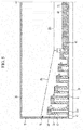
FIG. 5 , thespray nozzles 50 are installed at both sides based on the auxiliary spray nozzle 60 (FIG. 5 illustrates only one side), and heights h1 to h6 of the upper ends of thespray nozzles 50 are increased in proportion to distances d at which thespray nozzles 50 are spaced apart from the auxiliary spray nozzle 60 (or the central portion of the inner accommodation space). Therefore, the heights h1 to h6 of thecoolant inlet ports 54a are increased in proportion to a separation distance. In addition, a height h0 of the upper end of theauxiliary spray nozzle 60 is lower than the heights h1 to h6 of the upper ends of thespray nozzles 50. -
FIGS. 9 and10 are views illustrating a state in which the cooling device illustrated inFIGS. 5 and8 operates. Hereinafter, a method of operating the cooling device will be described below with reference toFIGS. 9 and10 . As described above, the coolant is supplied into the inner accommodation space of the cooling device (specifically, the inner tub 20) through thesupply pipe 35. The coolant is supplied into the inner accommodation space through the supply holes 35a, and foreign substances may be filtered out bymesh holes 64a of thelower mesh 64 andmesh holes 62a of theupper mesh 62. In this case, a diameter of themesh hole 64a may be larger than a diameter of themesh hole 62a. - As illustrated in
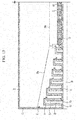
FIG. 10 , the coolant flows into the outer accommodation space while flowing over the front side plate and the rear side plate of theinner tub 20. Thereafter, as illustrated inFIG. 9 , in accordance with a level of the coolant accommodated in the outer accommodation space, the coolant flows into theauxiliary spray nozzle 60 through thecoolant inlet ports 62 and then is sprayed toward thestrip 1, and the coolant flows into thespray nozzles 50 through thecoolant inlet ports 54a and then is sprayed toward thestrip 1. - That is, as the level of the coolant is increased, the coolant is sprayed first through the
coolant inlet ports 62, and then the coolant is sprayed sequentially through thecoolant inlet ports 54a in the order from thecoolant inlet port 54a positioned at a lowest position to thecoolant inlet port 54a positioned at a highest position. Therefore, when an operator intends to adjust a width of the coolant to be fed, the operator adjusts the level of the coolant in the outer accommodation space, such that whether the coolant is supplied into thespray nozzles 50 is determined based on the level of the coolant, and as a result, it is possible to adjust a cooling range for thestrip 1. - In this case, as illustrated in
FIG. 9 , thespray plate 40 is installed to be higher than a lower end of theinner tub 20 and a lower end of theouter tub 30, and the coolant sprayed from thespray plate 40 is guided by a lower portion of theinner tub 20 and a lower portion of theouter tub 30 which protrude toward a lower portion of thespray plate 40, thereby preventing the coolant from being sprayed toward an unnecessary portion. - While the present invention has been described in detail with reference to the exemplary embodiment, other exemplary embodiments may be made in other forms. Accordingly, the technical spirit and the scope of the appended claims are not limited to the exemplary embodiment.
- Hereinafter, exemplary embodiments of the present invention will be described in more detail with reference to
FIGS. 11 to 13 . The exemplary embodiments of the present invention may be modified in various forms, and the scope of the present invention should not be interpreted as being limited to the following exemplary embodiment. The exemplary embodiments of the present invention are provided to more completely explain the present invention to those skilled in the art. Therefore, the shapes of the respective elements illustrated in the drawings may be exaggerated to emphasize a clearer description. -
FIGS. 11 and12 are views illustrating a process of adjusting a height of the spray nozzle illustrated inFIG. 5 . As described above, it is possible to adjust a height of thespray nozzle 50 by rotating thenozzle body 52, and it is possible to adjust a height of thecoolant inlet port 54a by rotating thenozzle cap 54. - As illustrated in
FIG. 11 , when thenozzle cap 54 is rotated, the height of thecoolant inlet port 54a is increased, and as a result, it is possible to prevent the coolant from flowing into thespray nozzle 50 through thecoolant inlet port 54a (compared toFIG. 9 ). On the contrary, when thenozzle cap 54 is rotated and the height of thecoolant inlet port 54a is decreased, the coolant may flow into thespray nozzle 50 through thecoolant inlet port 54a. That is, a user may determine, for eachspray nozzle 50, whether to spray the coolant through thespray nozzle 50 by rotating thenozzle cap 54 regardless of the level of the coolant (because an operation of adjusting the level of the coolant requires a large amount of time and affects all of the spray nozzles 50), and as a result, it is possible to spray the coolant asymmetrically based on the center of thestrip 1. - As illustrated in
FIG. 12 , when thenozzle body 52 is rotated, the height of thecoolant inlet port 54a is increased, and as a result, it is possible to prevent the coolant from flowing into thespray nozzle 50 through thecoolant inlet port 54a (compared toFIG. 9 ). On the contrary, when thenozzle body 52 is rotated and the height of thecoolant inlet port 54a is decreased, the coolant may flow into thespray nozzle 50 through thecoolant inlet port 54a. That is, it is possible to determine, for eachspray nozzle 50, whether to spray the coolant through thespray nozzle 50 by rotating thenozzle body 52, and as a result, it is possible to spray the coolant asymmetrically based on the center of thestrip 1. - Meanwhile, the present exemplary embodiment has described that the height of the
coolant inlet port 54a is adjusted by rotating thenozzle cap 54 or thenozzle body 52, but the scope of the present invention is not limited thereto, and it is possible to adjust the height of thecoolant inlet port 54a through another exemplary embodiment. In addition, thenozzle cap 54 or thenozzle body 52 may be rotated by a driving device such as a motor. -
FIG. 13 is a view illustrating a modified example of the cooling device illustrated inFIG. 5 . UnlikeFIG. 5 described above, a coolant inlet port 52a may be formed at a lateral side of thespray nozzle 50. As illustrated inFIG. 13 , thespray nozzles 50 are installed at both sides based on the auxiliary spray nozzle 60 (FIG. 5 illustrates only one side), and heights h1 to h6 of thecoolant inlet ports 54a are increased in proportion to distances d at which thespray nozzles 50 are spaced apart from the auxiliary spray nozzle 60 (or the central portion of the inner accommodation space). - While the present invention has been described in detail with reference to the exemplary embodiments, other exemplary embodiments may be made in other forms. Accordingly, the technical spirit and the scope of the appended claims are not limited to the exemplary embodiments.
- The present invention may be applied to various types of cooling devices.
Claims (19)
- A cooling device comprising:a tub which is disposed above a cooling target and has an accommodation space that accommodates a coolant; andspray nozzles which are installed in the accommodation space, each of the spray nozzles having one or more coolant inlet ports into which the coolant flows, the spray nozzles being disposed to be spaced apart from a central portion of the accommodation space toward an edge portion of the accommodation space, and the spray nozzles spraying the coolant toward the cooling target,wherein heights of the coolant inlet ports are in proportion to distances at which the spray nozzles are spaced apart from the central portion of the accommodation space.
- The cooling device of claim 1, wherein:the tub has a spray plate having multiple installation holes which are disposed to be spaced apart from one another and each have an internal screw thread formed on an inner circumferential surface thereof, andthe spray nozzle has an external screw thread which is formed on an outer circumferential surface of the spray nozzle and fastened to the internal screw thread of the installation hole by a threaded connection, such that a position of the spray nozzle is adjusted by a rotation of the spray nozzle.
- The cooling device of claim 1 or claim 2, wherein:
the spray nozzles are arranged in a direction in parallel with a width direction of the cooling target. - The cooling device of claim 2, wherein:
the spray nozzle includes:a nozzle body which has the external screw thread, is disposed to be approximately perpendicular to the spray plate, and has a spray flow path formed therein and a spray port formed at a lower end of the spray flow path; anda nozzle cap which is fastened to an upper portion of the nozzle body and has the multiple coolant inlet ports. - The cooling device of claim 4, wherein:
the nozzle cap is fastened to the nozzle body by a threaded connection, such that a height of the coolant inlet port is adjustable by a rotation of the nozzle cap. - The cooling device of claim 2, wherein:the spray plate has auxiliary installation holes which are disposed to be spaced apart from one another while penetrating one surface facing the cooling target and positioned at a central portion of the accommodation space, andthe cooling device further includes an auxiliary spray nozzle having auxiliary inlet ports which are in communication with the auxiliary installation holes and disposed to be lower than a height of the coolant inlet port.
- The cooling device of claim 1, wherein:
the tub includes:an inner tub which has side plates disposed in parallel with a direction in which the spray nozzles are spaced apart from one another; anda supply pipe which supplies the coolant into the inner tub, andthe side plate has a central portion and an edge portion having an upper end higher than an upper end of the central portion. - The cooling device of claim 7, wherein:
a height of the upper end of the edge portion is gradually increased toward an edge portion of the accommodation space. - The cooling device of claim 7, further comprising:
meshes which are fixedly installed on an inner circumferential surface of the inner tub and disposed in parallel with a direction in which the spray nozzles are spaced apart from one another. - The cooling device of claim 9, wherein:
the meshes have an upper mesh and a lower mesh positioned below the upper mesh. - The cooling device of claim 9, wherein:
the supply pipe is installed at a center of the accommodation space, and the meshes are disposed at both sides of the supply pipe and in contact with the supply pipe. - The cooling device of claim 2, wherein:
the tub includes:an inner tub which has side plates disposed in parallel with a direction in which the accommodation space and the spray nozzles are spaced apart from one another; andan outer tub which is disposed outside the inner tub and surrounds the inner tub, andthe spray plate is disposed between the inner tub and the outer tub and disposed to be higher than a lower end of the inner tub and a lower end of the outer tub. - The cooling device of claim 12, wherein:
the tub further has an auxiliary accommodation space which is positioned between the inner tub and the outer tub and formed above the spray plate. - A cooling device comprising:a tub which is disposed above a cooling target and has an accommodation space that accommodates a coolant supplied from the outside; andspray nozzles which are installed in the accommodation space and have coolant inlet ports into which the coolant selectively flows in accordance with a level of the coolant, and spray ports through which the coolant is sprayed toward the cooling target.
- The cooling device of claim 14, wherein:
heights of the coolant inlet port are gradually increased in a width direction of the cooling target. - The cooling device of claim 14, wherein:
the tub has an inner accommodation space into which the coolant is supplied, and an outer accommodation space into which the coolant overflowing from the inner accommodation space flows, and the spray nozzles are installed in the outer accommodation space. - The cooling device of claim 16, wherein:
the tub has a side plate which defines the inner accommodation space and the outer accommodation space, and a height of a central portion of the side plate is lower than heights of edge portions positioned at both sides of the central portion. - The cooling device of claim 17, wherein:
a height of the side plate in the width direction of the cooling target is higher than heights of the spray nozzles. - The cooling device of claim 14, further comprising:an auxiliary spray nozzle which is installed at a center of the accommodation space and has auxiliary inlet ports disposed to be lower than heights of the coolant inlet ports,wherein the spray nozzles are disposed at both sides of the auxiliary spray nozzle.
Applications Claiming Priority (2)
| Application Number | Priority Date | Filing Date | Title |
|---|---|---|---|
| KR1020150181265A KR101726763B1 (en) | 2015-12-17 | 2015-12-17 | Apparatus for cooling |
| PCT/KR2015/013995 WO2017104881A1 (en) | 2015-12-17 | 2015-12-21 | Cooling device |
Publications (2)
| Publication Number | Publication Date |
|---|---|
| EP3391977A1 true EP3391977A1 (en) | 2018-10-24 |
| EP3391977A4 EP3391977A4 (en) | 2019-01-23 |
Family
ID=58579711
Family Applications (1)
| Application Number | Title | Priority Date | Filing Date |
|---|---|---|---|
| EP15910802.6A Withdrawn EP3391977A4 (en) | 2015-12-17 | 2015-12-21 | Cooling device |
Country Status (6)
| Country | Link |
|---|---|
| US (1) | US20190084021A1 (en) |
| EP (1) | EP3391977A4 (en) |
| JP (1) | JP2018538144A (en) |
| KR (1) | KR101726763B1 (en) |
| CN (1) | CN108633264B (en) |
| WO (1) | WO2017104881A1 (en) |
Families Citing this family (3)
| Publication number | Priority date | Publication date | Assignee | Title |
|---|---|---|---|---|
| KR102010057B1 (en) * | 2017-12-11 | 2019-08-12 | 주식회사 포스코 | Cooling apparatus |
| KR102217531B1 (en) * | 2018-11-21 | 2021-02-19 | 주식회사 포스코 | Hot strip cooling apparatus and control system of the same |
| KR102300915B1 (en) * | 2020-05-27 | 2021-09-10 | 현대제철 주식회사 | Uniform cooling device for hot-rolled steel sheet and control method therefor |
Family Cites Families (23)
| Publication number | Priority date | Publication date | Assignee | Title |
|---|---|---|---|---|
| GB2035526B (en) * | 1978-10-02 | 1983-08-17 | Centre Rech Metallurgique | Cooling of rolled metal products |
| JPS57164916A (en) * | 1981-04-06 | 1982-10-09 | Toyota Central Res & Dev Lab Inc | Cooler for solution heat treatment of stainless steel material |
| JPS60160914U (en) * | 1984-04-05 | 1985-10-25 | 川崎製鉄株式会社 | Upper nozzle header for controlled cooling |
| JPS6173648U (en) * | 1984-10-23 | 1986-05-19 | ||
| JPS62179106U (en) * | 1986-05-06 | 1987-11-13 | ||
| JPH01178309A (en) * | 1987-12-29 | 1989-07-14 | Nippon Steel Corp | Device for cooling of hot rolled steel sheet |
| JPH0739446Y2 (en) * | 1990-07-28 | 1995-09-13 | 住友金属工業株式会社 | Slit laminar cooling device for hot steel sheets |
| JPH0518713U (en) * | 1991-08-14 | 1993-03-09 | 新日本製鐵株式会社 | Water cooling controller for hot rolled steel sheet |
| JPH0641905U (en) * | 1992-11-30 | 1994-06-03 | 住友金属工業株式会社 | Slit laminar cooling device |
| US5390900A (en) * | 1994-04-26 | 1995-02-21 | Int Rolling Mill Consultants | Metal strip cooling system |
| JPH08266939A (en) * | 1995-03-30 | 1996-10-15 | Kawasaki Steel Corp | Header device |
| JP3397278B2 (en) * | 1995-10-27 | 2003-04-14 | 新日本製鐵株式会社 | Laminar header for strip cooling system |
| KR100311782B1 (en) * | 1996-08-14 | 2001-12-17 | 이구택 | Lamina flow cooling device capable of horizontal uniform cooling |
| JP2000051921A (en) * | 1998-08-03 | 2000-02-22 | Nkk Corp | Apparatus and method for cooling high-temperature steel sheet |
| DE10025639A1 (en) * | 2000-05-24 | 2001-11-29 | Sms Demag Ag | Nozzle bar for cooling or descaling metal billets, especially rolled stock |
| KR100560805B1 (en) * | 2001-06-29 | 2006-03-14 | 주식회사 포스코 | Rolling oil injector variable to strip width |
| CN2684971Y (en) * | 2004-01-06 | 2005-03-16 | 朱萃汉 | A continuous casting two-cooling chamber casting blank gas cooling apparatus |
| KR100547477B1 (en) * | 2004-06-30 | 2006-01-31 | 주식회사 포스코 | Cooling header for steel sheet cooling equipment |
| KR101008071B1 (en) * | 2008-05-29 | 2011-01-13 | 주식회사 포스코 | Rolling Line Cooling Equipment |
| KR101253898B1 (en) * | 2010-12-23 | 2013-04-16 | 주식회사 포스코 | Cooling header |
| KR101330871B1 (en) * | 2011-10-28 | 2013-11-18 | 현대제철 주식회사 | Cooling device for rolling mill |
| KR101481616B1 (en) * | 2013-08-08 | 2015-01-12 | 주식회사 포스코 | Apparatus for cooling strip |
| CN104107839B (en) * | 2014-06-26 | 2016-06-29 | 武汉钢铁(集团)公司 | Improve method and the device of hot rolled steel plate ultra-rapid cooling uniformity |
-
2015
- 2015-12-17 KR KR1020150181265A patent/KR101726763B1/en active Active
- 2015-12-21 US US16/063,638 patent/US20190084021A1/en not_active Abandoned
- 2015-12-21 EP EP15910802.6A patent/EP3391977A4/en not_active Withdrawn
- 2015-12-21 JP JP2018531109A patent/JP2018538144A/en active Pending
- 2015-12-21 WO PCT/KR2015/013995 patent/WO2017104881A1/en not_active Ceased
- 2015-12-21 CN CN201580085790.0A patent/CN108633264B/en active Active
Also Published As
| Publication number | Publication date |
|---|---|
| EP3391977A4 (en) | 2019-01-23 |
| KR101726763B1 (en) | 2017-04-13 |
| JP2018538144A (en) | 2018-12-27 |
| CN108633264A (en) | 2018-10-09 |
| CN108633264B (en) | 2020-04-07 |
| WO2017104881A1 (en) | 2017-06-22 |
| US20190084021A1 (en) | 2019-03-21 |
Similar Documents
| Publication | Publication Date | Title |
|---|---|---|
| US20190084021A1 (en) | Cooling device | |
| CN111085571B (en) | Method for eliminating transverse roll marks after strip steel is leveled | |
| US20150140225A1 (en) | Method and device for hot-dip coating a metal strip with a metal covering | |
| JP2003094106A (en) | Method and apparatus for cooling steel sheet | |
| KR20040046126A (en) | A uniform laminar flow system to width direction of strip | |
| JP2009274101A (en) | Control method and control device for roll coolant in foil rolling machine | |
| RU2597188C2 (en) | Method and device for removal of scale from surface of metal article | |
| KR101394447B1 (en) | Hot rolling apparatus and method for manufacturing hot rolled steel strip | |
| JP7406093B2 (en) | Cooling device and method for hot-rolled steel sheets | |
| CN100443204C (en) | Control method and control device for rolling device | |
| JP2007144483A5 (en) | ||
| KR20130034211A (en) | An accelerated cooling apparatus | |
| JP6558344B2 (en) | Steel plate lower surface cooling device and lower surface cooling method | |
| KR100946039B1 (en) | Wire Rod Guide Device | |
| JP7352080B2 (en) | Cooling device and method for hot-rolled steel sheets | |
| TWI477328B (en) | Apparatus for cooling hot rolled steel sheet | |
| KR20110120522A (en) | Uniform cooling device of hot rolled steel | |
| KR101054383B1 (en) | Hot Rolling Process Equipment and Hot Rolling Method for Shape Correction of Hot Rolled Steel Sheets | |
| KR101758559B1 (en) | Apparatus for cooling of wire-rod and Rolling facilities having the same | |
| KR101536906B1 (en) | Cooling apparatus for material | |
| JP4760403B2 (en) | Thermal crown control device, rolling mill, and metal strip manufacturing method using the rolling mill | |
| RU2701595C1 (en) | Device and method for manufacturing a workpiece of a given type | |
| KR101767831B1 (en) | Descaler | |
| KR20130023685A (en) | Apparatus for detecting position of hot rolled steel sheet in accelerating cooler | |
| KR101988284B1 (en) | Materials treatment apparatus |
Legal Events
| Date | Code | Title | Description |
|---|---|---|---|
| PUAI | Public reference made under article 153(3) epc to a published international application that has entered the european phase |
Free format text: ORIGINAL CODE: 0009012 |
|
| 17P | Request for examination filed |
Effective date: 20180717 |
|
| AK | Designated contracting states |
Kind code of ref document: A1 Designated state(s): AL AT BE BG CH CY CZ DE DK EE ES FI FR GB GR HR HU IE IS IT LI LT LU LV MC MK MT NL NO PL PT RO RS SE SI SK SM TR |
|
| AX | Request for extension of the european patent |
Extension state: BA ME |
|
| A4 | Supplementary search report drawn up and despatched |
Effective date: 20190103 |
|
| RIC1 | Information provided on ipc code assigned before grant |
Ipc: B21B 45/02 20060101AFI20181219BHEP |
|
| DAV | Request for validation of the european patent (deleted) | ||
| DAX | Request for extension of the european patent (deleted) | ||
| 17Q | First examination report despatched |
Effective date: 20200110 |
|
| STAA | Information on the status of an ep patent application or granted ep patent |
Free format text: STATUS: THE APPLICATION IS DEEMED TO BE WITHDRAWN |
|
| 18D | Application deemed to be withdrawn |
Effective date: 20200603 |