EP3391869A2 - Electric vehicle, method of controlling electric vehicle, computer program, and elecric rollator - Google Patents
Electric vehicle, method of controlling electric vehicle, computer program, and elecric rollator Download PDFInfo
- Publication number
- EP3391869A2 EP3391869A2 EP18167748.5A EP18167748A EP3391869A2 EP 3391869 A2 EP3391869 A2 EP 3391869A2 EP 18167748 A EP18167748 A EP 18167748A EP 3391869 A2 EP3391869 A2 EP 3391869A2
- Authority
- EP
- European Patent Office
- Prior art keywords
- user
- braking
- electric vehicle
- support pad
- rollator
- Prior art date
- Legal status (The legal status is an assumption and is not a legal conclusion. Google has not performed a legal analysis and makes no representation as to the accuracy of the status listed.)
- Granted
Links
Images




Classifications
-
- A—HUMAN NECESSITIES
- A61—MEDICAL OR VETERINARY SCIENCE; HYGIENE
- A61H—PHYSICAL THERAPY APPARATUS, e.g. DEVICES FOR LOCATING OR STIMULATING REFLEX POINTS IN THE BODY; ARTIFICIAL RESPIRATION; MASSAGE; BATHING DEVICES FOR SPECIAL THERAPEUTIC OR HYGIENIC PURPOSES OR SPECIFIC PARTS OF THE BODY
- A61H3/00—Appliances for aiding patients or disabled persons to walk about
- A61H3/04—Wheeled walking aids for patients or disabled persons
-
- A—HUMAN NECESSITIES
- A61—MEDICAL OR VETERINARY SCIENCE; HYGIENE
- A61H—PHYSICAL THERAPY APPARATUS, e.g. DEVICES FOR LOCATING OR STIMULATING REFLEX POINTS IN THE BODY; ARTIFICIAL RESPIRATION; MASSAGE; BATHING DEVICES FOR SPECIAL THERAPEUTIC OR HYGIENIC PURPOSES OR SPECIFIC PARTS OF THE BODY
- A61H3/00—Appliances for aiding patients or disabled persons to walk about
- A61H3/04—Wheeled walking aids for patients or disabled persons
- A61H2003/043—Wheeled walking aids for patients or disabled persons with a drive mechanism
-
- A—HUMAN NECESSITIES
- A61—MEDICAL OR VETERINARY SCIENCE; HYGIENE
- A61H—PHYSICAL THERAPY APPARATUS, e.g. DEVICES FOR LOCATING OR STIMULATING REFLEX POINTS IN THE BODY; ARTIFICIAL RESPIRATION; MASSAGE; BATHING DEVICES FOR SPECIAL THERAPEUTIC OR HYGIENIC PURPOSES OR SPECIFIC PARTS OF THE BODY
- A61H3/00—Appliances for aiding patients or disabled persons to walk about
- A61H3/04—Wheeled walking aids for patients or disabled persons
- A61H2003/046—Wheeled walking aids for patients or disabled persons with braking means
-
- A—HUMAN NECESSITIES
- A61—MEDICAL OR VETERINARY SCIENCE; HYGIENE
- A61H—PHYSICAL THERAPY APPARATUS, e.g. DEVICES FOR LOCATING OR STIMULATING REFLEX POINTS IN THE BODY; ARTIFICIAL RESPIRATION; MASSAGE; BATHING DEVICES FOR SPECIAL THERAPEUTIC OR HYGIENIC PURPOSES OR SPECIFIC PARTS OF THE BODY
- A61H2201/00—Characteristics of apparatus not provided for in the preceding codes
- A61H2201/16—Physical interface with patient
- A61H2201/1602—Physical interface with patient kind of interface, e.g. head rest, knee support or lumbar support
- A61H2201/1628—Pelvis
- A61H2201/1633—Seat
-
- A—HUMAN NECESSITIES
- A61—MEDICAL OR VETERINARY SCIENCE; HYGIENE
- A61H—PHYSICAL THERAPY APPARATUS, e.g. DEVICES FOR LOCATING OR STIMULATING REFLEX POINTS IN THE BODY; ARTIFICIAL RESPIRATION; MASSAGE; BATHING DEVICES FOR SPECIAL THERAPEUTIC OR HYGIENIC PURPOSES OR SPECIFIC PARTS OF THE BODY
- A61H2201/00—Characteristics of apparatus not provided for in the preceding codes
- A61H2201/16—Physical interface with patient
- A61H2201/1602—Physical interface with patient kind of interface, e.g. head rest, knee support or lumbar support
- A61H2201/1635—Hand or arm, e.g. handle
-
- A—HUMAN NECESSITIES
- A61—MEDICAL OR VETERINARY SCIENCE; HYGIENE
- A61H—PHYSICAL THERAPY APPARATUS, e.g. DEVICES FOR LOCATING OR STIMULATING REFLEX POINTS IN THE BODY; ARTIFICIAL RESPIRATION; MASSAGE; BATHING DEVICES FOR SPECIAL THERAPEUTIC OR HYGIENIC PURPOSES OR SPECIFIC PARTS OF THE BODY
- A61H2201/00—Characteristics of apparatus not provided for in the preceding codes
- A61H2201/16—Physical interface with patient
- A61H2201/1657—Movement of interface, i.e. force application means
- A61H2201/1676—Pivoting
-
- A—HUMAN NECESSITIES
- A61—MEDICAL OR VETERINARY SCIENCE; HYGIENE
- A61H—PHYSICAL THERAPY APPARATUS, e.g. DEVICES FOR LOCATING OR STIMULATING REFLEX POINTS IN THE BODY; ARTIFICIAL RESPIRATION; MASSAGE; BATHING DEVICES FOR SPECIAL THERAPEUTIC OR HYGIENIC PURPOSES OR SPECIFIC PARTS OF THE BODY
- A61H2201/00—Characteristics of apparatus not provided for in the preceding codes
- A61H2201/50—Control means thereof
- A61H2201/5023—Interfaces to the user
- A61H2201/5025—Activation means
- A61H2201/5028—Contact activation, i.e. activated at contact with a surface of the user to be treated
-
- A—HUMAN NECESSITIES
- A61—MEDICAL OR VETERINARY SCIENCE; HYGIENE
- A61H—PHYSICAL THERAPY APPARATUS, e.g. DEVICES FOR LOCATING OR STIMULATING REFLEX POINTS IN THE BODY; ARTIFICIAL RESPIRATION; MASSAGE; BATHING DEVICES FOR SPECIAL THERAPEUTIC OR HYGIENIC PURPOSES OR SPECIFIC PARTS OF THE BODY
- A61H2201/00—Characteristics of apparatus not provided for in the preceding codes
- A61H2201/50—Control means thereof
- A61H2201/5058—Sensors or detectors
- A61H2201/5064—Position sensors
-
- A—HUMAN NECESSITIES
- A61—MEDICAL OR VETERINARY SCIENCE; HYGIENE
- A61H—PHYSICAL THERAPY APPARATUS, e.g. DEVICES FOR LOCATING OR STIMULATING REFLEX POINTS IN THE BODY; ARTIFICIAL RESPIRATION; MASSAGE; BATHING DEVICES FOR SPECIAL THERAPEUTIC OR HYGIENIC PURPOSES OR SPECIFIC PARTS OF THE BODY
- A61H2201/00—Characteristics of apparatus not provided for in the preceding codes
- A61H2201/50—Control means thereof
- A61H2201/5058—Sensors or detectors
- A61H2201/5084—Acceleration sensors
Definitions
- the present disclosure relates to an electric vehicle, a method of controlling the electric vehicle, a computer program, and an electric rollator.
- an electric vehicle called a rollator equipped with an electric motor to assist the elderly and people with reduced walking ability in walking.
- Such an electric vehicle is also called an electric rollator.
- the electric rollator is used for moving together with a walking person (user) when the user walks, and drives the motors of wheels to generate a force to offset inadequacy of an operation force applied by the user.
- the electric rollator assists walking of the user.
- the user with reduced walking ability can easily walk using the force generated by the electric rollator.
- the electric rollator does not start to move against a user's intention (e.g., malfunction).
- the electric rollator is also used as a seat for the user when the user goes outside. It is preferable that a vehicle body stops before the user sits thereon and stays still when the user sits thereon. It is preferable that the electric rollator does not go down a slope even when the user releases both hands from the electric rollator for some reason when the electric rollator travels downhill.
- the electric rollator which does not move against a user's intention.
- the electric vehicle includes a detector (72) which detects a load applied by a part of a body of a user to a body supporter (14), or contact between the body of the user and the body supporter and generates a detection signal; and a controller (90) which controls braking of a wheel (12 or 13) or a continuous track based on the detection signal.
- the load applied to the body supporter may be a load applied by the user in a direction perpendicular to a surface on which the electric vehicle is placed.
- the body supporter may be relatively movable according to the load applied thereto with respect to a body frame including the detector.
- the detection signal may include information specifying a distance between the body supporter and the detector, or information whether the distance is a certain value or less.
- the controller may release the braking when the distance is the certain value or less, and perform the braking when the distance is not the certain value or less.
- an energization member may is arranged between the body supporter and the body frame, which energizes the body supporter in a direction away from the body frame.
- the detector may be a proximity sensor arranged in the body frame, the body supporter may be provided with an object capable of being detected by the proximity sensor, and the controller may release the braking when the proximity sensor detects the object, and perform the braking when the proximity sensor does not detect the object.
- the body supporter may prevent the user from sitting on a seat of the electric vehicle when the body supporter is in a normal position, and permit the user to sit on the seat when the body supporter is in a retracted position different from the normal position.
- the controller may detect an inclination of the electric vehicle, and switch a type of the braking according to the inclination.
- the controller may perform reverse braking when a magnitude of the inclination of the electric vehicle is a certain value or more, and perform rheostatic braking when the magnitude of the inclination of the electric vehicle is smaller than the certain value.
- the controller may perform rheostatic braking when mechanical braking is performed.
- a method of controlling an electric vehicle includes: detecting a load applied by a part of a body of a user to a body supporter, or contact between the body of the user and the body supporter, and generating a detection signal; and controlling braking of a wheel or a continuous track based on the detection signal.
- a computer readable medium stores therein a computer program causing a computer to execute: receiving a detection signal depending on a load applied by a part of a body of a user to a body supporter (14), or depending on contact between the body of the user and the body supporter; and controlling braking of a wheel or a continuous track based on the detection signal.
- an electric rollator includes: a body frame provided with a wheel; a body supporter supporting a part of a body of a user, which is relatively movable according to a load applied thereto by the user with respect to the body frame; a detector provided in the body frame, which generates a detection signal depending on a distance between the body supporter and the detector; and a controller which controls braking of the wheel based on the detection signal, and which releases the braking when the distance is a certain value or less, and performs the braking when the distance is not the certain value or less.
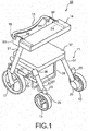
- FIG. 1 is a perspective view schematically illustrating an electric rollator (hereinafter referred to as a rollator) 100 as one example of an electric vehicle according to an embodiment.
- FIG. 2 is a side view of the rollator 100 in FIG. 1 .
- the rollator 100 includes a body frame 11, a pair of front wheels 12 and a pair of rear wheels 13 that are provided to the body frame 11, and a support pad (body supporter) 14 that is provided to the body frame 11.
- the rollator 100 is used to assist walking of the elderly and people with reduced walking ability.
- the user places the forearms or the elbows on the support pad 14 to apply a user's weight (load) to the support pad 14, and performs walking operation while gripping a handle bar 15 and a brake lever 16.
- the rollator 100 drives motors 20 connected to rear wheels 13 to generate a force to offset inadequacy of a force applied by the user so that the rollator 100 can autonomously travel, thereby performing a walking assist control.
- a control system (see FIG. 6 described later) for performing such an assist control is mounted on the rollator 100 in FIG. 1 .
- the rollator 100 in FIG. 1 will be further described in detail.
- the body frame 11 is provided with a pair of support frames 21 inclined by a predetermined angle from a direction perpendicular to a surface (e.g., ground surface) on which the rollator 100 is placed.
- the support frame 21 is made of a pipe-shaped member, as an example.
- a pair of lower frames 51 are horizontally disposed at lower ends of the support frames 21, respectively.
- a pair of front wheels 12 is attached to front ends of the lower frames 51, respectively.
- a pair of link mechanisms 55 is provided to rear end side of the lower frames 51.
- a pair of upper frames 54 is disposed above the pair of lower frames 51, respectively.
- One ends of a pair of rear wheel frames 57 are rotatably coupled to rear ends of the pair of upper frames 54, respectively, through a shaft 56.
- the pair of rear wheels 13 are provided respectively.
- a pair of motors 20 to drive the respective corresponding rear wheels 13 is connected to the pair of rear wheels 13.
- the motor 20 used may be any motor such as a servomotor, a stepping motor, an AC motor, or a DC motor.
- a motor integrally formed with a reducer may be used.
- a pair of handles 24 is provided on upper ends of the pair of support frames 21, respectively.
- the pair of handles 24 are substantially horizontally disposed with respect to the surface on which the rollator 100 is placed, and are made of a pipe-shaped member, as an example.
- Grips 23 that the user grips are provided at the pair of handles 24, respectively, so that the user can stabilize the posture of the user when the user sits.
- the pipe-shaped handle bar 15 is formed at front sides of the pair of handles 24 to integrate with the handles 24. One end of the handle bar 15 is connected to one of the pair of handles 24, and the other end of the handle bar 15 is connected to the other of the handles 24.
- the handle bar 15 may be made of a material different from the material of the handles 24.
- a pair of brake shoes 25 (not illustrated in FIG. 1 , but illustrated in FIG. 2 ) are provided on outer peripheries of the pair of rear wheels 13, respectively, such that they can be mechanically brought into contact with the rear wheels 13.
- the brake shoes 25 are connected to one ends of brake wires (hereinafter referred to as wires) disposed in the body frame 11, and the other ends of the wires are connected to wire connection mechanisms of a pair of brake units 61 that are provided on both sides of the handle bar 15, respectively.
- the wires are stored in the body frame 11, but may be arranged outside the body frame to be apparently visible from the user.
- a brake lever 16 is disposed in a front lower direction of the handle bar 15 to face the handle bar 15.
- the pair of brake units 61 is connected to both ends of the brake lever 16, respectively.
- the both ends of the brake lever 16 are attached to the brake units 61, respectively, through energizers such as coil springs.
- the user pulls the brake lever 16 toward the user (in a direction of an arrow R1 in FIG. 2 ), thereby applying the mechanical braking using wire action. That is, the operation of the brake lever 16 enables the brake shoes 25 to be controlled.
- the user pulls the brake lever 16 toward the user (in a direction of approaching the handle bar 15) to reach a brake activation position.
- the brake shoes 25 are moved by the action of the wires connected to the brake lever 16 to then be pressed against the outer peripheries of the rear wheels 13.
- the mechanical braking is applied.
- the brake lever 16 is returned to an original position (normal position).
- the brake shoes 25 are also released from the rear wheels 13 to release the mechanical braking.
- the brake lever 16 can be also moved in a direction opposite to the arrow R1 (downward direction).
- the brake lever 16 When the brake lever 16 is moved downward to the parking position, the parking brake is applied to maintain a state in which the brake shoes 25 are pressed against the rear wheels 13 using the wire action.
- the brake lever 16 may be electrically connected to a user IF substrate (see FIG. 6 ) through a wire in the body frame 11.
- a brake switch is attached to the brake lever 16 or the brake unit 61, to be capable of notifying a state of the brake lever 16 (position of the brake lever 16 such as the normal position, the brake activation position, or the parking position) to the user IF substrate.
- the support pad 14 is mounted above the pair of handles 24 to cover over the pair of handles 24.
- the support pad 14 is a form of a body supporter for supporting a part of the body of the user. In the present embodiment, it is assumed that the forearms, the elbows, or both of them of the user are supported on the support pad 14. Note that a using form for supporting another portion such as a jaw, hands, or a chest may be applied.
- a detection mechanism 71 is provided between the handles 24 and the support pad 14, to detect whether the user uses the rollator 100 for walking. Specifically, the detection mechanism 71 detects whether a load (weight) of the user is applied to the support pad 14, or whether the user is in contact with the support pad 14. The detail of the detection mechanism 71 will be described later.
- the support pad 14 has a horseshoe shape, as an example, but the support pad 14 is not limited to this shape, and may be any other shape.
- the support pad 14 is configured by placing a cushion material such as a sponge or a rubber material on a plate material such as a wood plate, or a resin plate to be covered with any coating material made of resin or cloth, as an example. However, the support pad 14 is not limited to this configuration, and may have any other configuration.
- FIG. 3 illustrates a state of the support pad 14 after being rotated.
- a space for housing an upper body of the user can be formed above a seat 37. In this state, the user can turn the user's back toward the support pad 14 while gripping the pair of grips 23 with both hands, and sit on the seat 37.
- the user can stabilize the posture of the user by gripping the grips 23 when the user sits on the seat 37.
- the support pad 14 prevents the user from sitting on the seat 37 of the rollator at a position before being flipped up (normal position), and allows the user to sit on the seat 37 at a position after being flipped up (retracted position).
- the support pad 14 is configured to be manually flipped up by the user, but a lock mechanism (not illustrated) may be provided to release the fixing of the support pad 14, and thereby automatically flip up the support pad 14, as another example.
- a lock mechanism (not illustrated) may be provided to release the fixing of the support pad 14, and thereby automatically flip up the support pad 14, as another example.
- an electric mechanism (a motor, or the like) for rotating the arm members 26 is provided to perform the electric mechanism by switch activation, and thereby flip up the support pad 14.
- a storage 27 (see FIG. 2 ) is provided between the pair of upper frames 54 such that the storage 27 is hung from the pair of upper frames 54.
- the storage 27 has a bag shape with an upward opening.
- the storage 27 may be made of resin or cloth.
- the above-described seat 37 for sitting is provided as a lid for the storage 27.
- the control system (see FIG. 6 ) described later is installed in the storage 27, the control system including a main control substrate 81, a user IF substrate 82, a battery 87, a speaker 85, and the like.
- a lever 28 is provided at a rear side of the storage 27, the lever 28 extending downwardly from the pair of upper frames 54.
- the lever 28 is disposed at a position where the user can press down the lever 28 with the user's foot.
- the pair of rear wheel frames 57 and the pair of rear wheels 13 are brought close to the pair of front wheels 12, resulting in that the link mechanisms 55 are folded up. In this manner, the rollator 100 can be folded up.
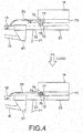
- FIG. 4 is a diagram illustrating a detailed configuration of the detection mechanism 71.
- An upper portion of FIG. 4 illustrates a state in which the user does not apply a load to the support pad 14.
- a lower portion of FIG. 4 illustrates a state in which the user applies a load to the support pad 14.
- a proximity sensor (detector) 72 that detects a magnet (object to be detected) 77 is fixed and installed in one handle 24 of the pair of handles 24.
- the proximity sensor 72 can detect the magnet 77 without physically contacting the magnet 77.
- the proximity sensor 72 is connected to the user IF substrate (see FIG. 6 ) described later through a wire in the body frame 11. A hall IC, etc.
- the proximity sensor 72 can be used as the proximity sensor 72, for example, the hall IC outputting an on (high-level or conductive) signal in a strength of a magnetic field being a certain value (threshold) or more, and an off (low-level or insulating) signal in a strength of a magnetic field being less than the certain value, but the proximity sensor 72 is not limited thereto.
- the relationship between the on signal and the off signal may be reversed: however, the configuration that the conductive signal is output in the strength of the magnetic field being the certain value or more is safe because the braking is applied when the signal line is disconnected. Note that the positional relationship between the magnet and the proximity sensor may be reversed.
- a pair of support members 73 is attached to both right and left lower sides of the support pad 14 to extend in a front-rear direction (a right-left direction along a plane of FIG. 4 ).
- a width of the support member 73 in the right-left direction is about the same as that of the handle 24 or the grip 23, or is slightly wider or narrower than the handle 24 or the grip 23, but is not limited thereto.
- the support member 73 is moved downwardly when the load is applied to the support pad 14 by the user (e.g., when the load is applied in the direction perpendicular to the the surface on which the rollator 100 is placed), and the support member 73 is pressed against the handle 24 (including the grip 23).
- the support pad 14 stops at a position corresponding to the thickness of the support member 73.
- a gap is formed to vertically penetrate the inside at the front end side of each of the pair of support members 73.
- a spring (energization member) 74 having an energization force in the vertical direction is disposed in the gap.
- a type of the spring 74 is a coil spring, as an example, but may have any other configuration. The energization member other than the spring may be used.
- An upper portion of the spring 74 is fixed to the support pad 14 through any protection member 75.
- a lower portion of the spring 74 is covered with a cap 76. The lower portion of the spring 74 protrudes from the bottom surface of the support member 73 in a state in which the load is not applied to the support pad 14, and is in contact with a top surface of the handle 24 through the cap 76.
- the spring 74 When the load is applied to the support pad 14 in this state, the spring 74 is compressed, and the portion protruding from the bottom surface of the support member 73 is housed in the gap in the support member 73, so that the support pad 14 is moved toward the handle 24 side, and the bottom surface of the support member 73 is pressed against the handle 24 and the grip 23.
- the cap 76 and the protection member 75 are made of resin as an example, but the materials of the cap 76 and the protection member 75 are not limited thereto.
- the magnet 77 is installed inside one (the support member on the same side as the handle in which the proximity sensor 72 is installed) of the pair of support members 73.
- the shape of the magnet 77 may be rectangular, cylindrical, or any other shape.
- the magnet 77 at least needs to be positioned so that the proximity sensor 72 cannot detect the magnet 77 in a state in which the load is not applied to the support pad 14, and the proximity sensor 72 can detect the magnet 77 in a state in which the load is applied to the support pad 14. If this condition is satisfied, the position of the magnet and the magnetic force can be arbitrary. However, since the support pad 14 may approach the handle 24 due to vibration during traveling even when the load is not applied to the support pad 14, the detection mechanism 71 needs to be configured to prevent the proximity sensor 72 from wrongly detecting the magnet 77 at this time.
- the magnetic force of the magnet be larger than the magnetic force of portable articles and personal ornaments normally used by the user.
- the proximity sensor 72 can be prevented from misdetection.
- the operation when the user applies the load to the support pad 14 will be described.
- the magnet 77 and the proximity sensor 72 are separated from each other. In this state, the proximity sensor 72 does not detect the magnet 77, and generates and outputs the off (low level) detection signal. Similarly, the proximity sensor 72 does not detect the magnet 77 when the support pad 14 is flipped up (see FIG. 3 ), and the proximity sensor 72 generates and outputs the off detection signal.
- the spring 74 is compressed, and a distance between the magnet 77 and the proximity sensor 72 is reduced.
- the distance from the magnet 77 is a certain value or less, i.e., when a movement amount of the magnet 77 (i.e., a movement amount of the support pad 14) is a certain value or more, the proximity sensor 72 detects the magnet 77 (i.e., support pad 14). The proximity sensor 72 generates and outputs the on (high level) detection signal when detecting the magnet 77.
- the detection signal of the proximity sensor 72 is input to the user IF substrate (see FIG. 6 ) described later through a wire (not illustrated).
- FIG. 5 is a graph showing an example of detection signal of the proximity sensor.
- the detection signal of the proximity sensor 72 is an on (high level) signal in a state in which the load is applied to the support pad 14.
- the detection signal of the proximity sensor 72 is changed to an off (low level) signal in a state in which the user is separated from the support pad 14, and the load is not applied to the support pad 14.
- the controller controls braking such as activation and release of the braking in accordance with the detection signal (output signal) as one of characteristics of the present embodiment. The details will be described later.
- FIG. 6 is a diagram illustrating an example of the control system that is mounted in the rollator 100 and a peripheral configuration of the control system.
- the control system in FIG. 6 includes a main control substrate 81, a user IF (InterFace) substrate 82, an operation panel 83, and adjustment panel 84, a speaker 85, a battery 87, and motors 20 (a right motor, a left motor).
- the motors 20 correspond to the motors 20 illustrated in FIG. 1 , respectively.
- the main control substrate 81, the user IF substrate 82, the speaker 85, and the battery 87 are disposed in the storage 27, as an example, but they may be partially or wholly disposed in another place.
- the main control substrate 81, the user IF substrate 82, or both of them may be provided with a clock (not illustrated).
- the battery 87 is used to supply electric power to each element of the motors 20, the main control substrate 81, and the user IF substrate 82.
- the battery 87 is a battery (secondary battery) capable of charging and discharging, but is not limited thereto.
- the operation panel 83 is a panel used for manually setting by the user such as on/off for a power source of the rollator 100, a voice volume, and the like.
- the adjustment panel 84 is a panel for setting of on/off for an assist control mode, adjusting the maximum speed, adjusting the strength of the braking.
- the operation panel 83 and the adjustment panel 84 are configured with liquid crystal touch panels, as an example, but may have any other configuration such as a button-type panel.
- the operation panel 83 and the adjustment panel 84 are provided at arbitrary positions (positions where the user can easily operate the panels) of the rollator 100.
- a unit for setting off the proximity sensor 72 may be provided to the operation panel 83.
- the proximity sensor 72 may be set off in a state in which the support pad 14 is flipped up, to perform the assist control.
- the user IF substrate 82 is connected to the adjustment panel 84, the operation panel 83, the main control substrate 81, the brake switch (brake SW) 86, the proximity sensor (pad switch) 72, and the speaker 85 through respective IFs.
- the brake switch 86 When detecting that the user has performed the brake operation or the parking brake operation with the brake lever 16, the brake switch 86 outputs a signal for notifying the operation.
- the proximity sensor 72 When detecting the magnet 77 (i.e., detecting that the support pad 14 has been pressed), the proximity sensor 72 outputs an on-signal, and outputs an off-signal otherwise.
- a lamp indicating that the brake operation or the parking brake operation has performed may be provided to the operation panel 83 or the adjustment panel 84.
- a lamp for notifying that the support pad 14 is pressed may be provided to the operation panel 83 or the adjustment panel 84.
- the user IF substrate 82 transmits, to the main control substrate 81, signals input from the proximity sensor 72, the brake SW 86, the adjustment panel 84, and the operation panel 83.
- the user IF substrate is also provided with the voice guide 89, and the voice guide 89 generates a voice guide signal based on signals input from the proximity sensor 72, the brake SW 86, the adjustment panel 84, and the operation panel 83, or based on a signal input from the main control substrate 81, and outputs it to the speaker 85.
- the speaker 85 outputs a voice based on the input signal.
- the speaker 85 When the user turns on the power source, for example, the speaker 85 outputs a voice message that "the power source has been turned on.” If the brake lever 16 is not moved downwardly (the parking brake is not applied) in a state in which the rollator 100 stops or the load is not applied to the support pad 14 for a certain time, the speaker 85 outputs a voice message prompting the user to apply the parking brake such as "please lower the brake lever.”. Alternatively, an LED mounted on the operation panel 83 may be used to visually display the warning.
- the main control substrate 81 includes a controller 90 for performing the entire control.
- the controller 90 is a program execution and arithmetic device such as a microcomputer, a processor, or a CPU.
- the controller 90 is a microcomputer.
- a non-volatile memory 91 stores a program code for operating the controller 90, information or data generated by the controller 90, information or data required to operate the controller 90, information or data received from the other elements, and the like.
- the controller 90 reads out and executes the program code in the non-volatile memory 91 to perform the control.
- the non-volatile memory 91 may be any memory such as a flash memory (a NAND memory, etc.), an MRAM, or an FRAM.
- the controller 90 may be not a program execution device, but a device such as an application specific integrated circuit (ASIC), or a field programmable gate array (FPGA).
- ASIC application specific integrated circuit
- FPGA field programmable gate array
- the controller 90 calculates the state (posture, etc.) of the rollator 100 using an acceleration sensor 92.
- the acceleration sensor 92 one or more of uniaxial, biaxial, and triaxial sensors may be used.
- a gyro sensor may be used instead of the acceleration sensor 92.
- the controller 90 specifies the state of the right motor 20 (e.g., rotation position, speed, the number of revolutions and the like of a rotor or a motor shaft) based on a signal of the hall IC incorporated in the right motor 20.
- the controller 90 specifies the state of the left motor 20 based on a signal of the hall IC incorporated in the left motor 20.
- the controller 90 controls (performs an assist control) the drive of both right and left motors 20 using these pieces of information to compensate a force to offset inadequacy of a force applied by the user.
- the controller 90 performs braking control based on a detection signal of the proximity sensor 72. Specifically, the controller 90 releases the braking when the detection signal is an on-signal (when the load is applied to the support pad 14), and the controller 90 controls to perform the braking when the detection signal is an off-signal (when the load is not applied to the support pad 14).
- Examples of the types of brake include a rheostatic braking, and a reverse braking.
- the type of brake to be used can be preliminarily determined or selected according to a situation (inclination of the rollator) as described later.
- the RHEOSTATIC braking is short-circuited among U, V, W phases of the motor 20 (normal drive is stopped), and obtains a braking force using a counter electromotive force generated by the rotation of the motor 20.
- regenerative braking can be employed.
- the smooth braking can be assured.
- the electric power can be regenerated. But the rollator 100 cannot be completely stopped, and the breaking force is weak.
- the reverse braking drives the motor backwardly when the wheels are moved in the forward direction, and drives the motor forwardly when the wheels are moved in the backward direction, so that the rollator body is stopped at the current location (i.e., immediately).
- the braking force is strong, and the rollator body can be stopped at the current location, but the power consumption is large, and the vibration is caused.
- the controller 90 may control to switch between the rheostatic braking and the reverse braking using the information on inclination of the rollator 100.
- the inclination of the rollator 100 can be detected using an inclination sensor 119, as an example.
- the inclination sensor 119 measures the inclination of the rollator body, and outputs a signal indicating the measured inclination as a detection signal.
- FIGS. 7(A) and 7(B) each is a diagram illustrating an example of braking control using the information on the inclination of the rollator 100.
- the controller 90 determines that the rollator body is placed on an inclined surface (slope, etc.) when a detection signal of the inclination sensor 119 indicates that the inclination angle is a certain angle or more. In this case, the controller 90 selects the reverse braking.
- the controller 90 determines that the rollator body is placed on a flat surface (flatland) when the detection signal of the inclination sensor 119 indicates that the inclination angle is below the certain angle. In this case, the controller 90 selects the rheostatic braking.
- the rollator body can be stopped even by the rheostatic braking.
- the use of the reverse braking causes increase in consumption power, but the use of the rheostatic braking with small power consumption saves the power consumption. Therefore, it is desirable to select the rheostatic braking on the flat surface.
- the inclined surface such as a slope
- the other brake that can stop the rollator body at the current location may be applied instead of the rheostatic braking or the reverse braking.
- the other brake there is the mechanical braking using the brake shoe 25.
- the controller 90 may be configured to control the mechanical braking, or the rheostatic braking or the reverse braking using a signal from a brake switch.
- the inclination sensor 119 is used to measure the inclination of the rollator 100, but the acceleration sensor 92 may be used to calculate the inclination of the rollator 100.
- the acceleration sensor 92 measures gravity acceleration to calculate the inclination. Accordingly, the acceleration sensor is one kind of the inclination sensor.
- a communication circuit that wiredly or wirelessly communicates in a predetermined communication scheme may be provided in the main control substrate 81 or the user IF substrate 82 to be communicable with an external device.
- the state of the rollator may be notified to the external device through communication, and the program in the non-volatile memory 91 may be updated by obtaining the update data from the external device.
- a threshold for controlling on/off of the proximity sensor 72 can be adjusted through communication.
- Examples of the states of the rollator 100 to be notified to the external device include a current position using a GPS (Global Positioning System), etc., and presence/absence of an occurrence of fault in the rollator 100, but are not limited thereto.
- the communication circuit may notify information for differentiating among a plurality of states: the state in which the load is applied to the support pad 14, the state in which the load is not applied to the support pad 14, and the state in which the support pad 14 is flipped up.
- the motor 20 is attached to each of the rear wheels 13, but the attachment of the motor 20 is not limited to the rear wheel 13, and the motor 20 may be attached only to each of the pair of front wheels 12. Alternatively, the motors 20 may be attached to all of the pair of front wheels 12 and the pair of rear wheels 13.
- the motor 20 has been used a brake of the wheel (rear wheel 13) in the description explained previously, but another brake for the wheel may be provided separately from the motor 20; the mechanical brake or an electromagnetic brake.
- the present embodiment has been described using an example in which the pair of rear wheels (wheels) 13 are driven by the motor 20, but is not limited thereto, and a continuous track in which a continuous band of track plates surrounds starting wheels, rollers, and idling wheels (guide wheels) may be driven by the motor.
- the continuous track is to be braked.
- the proximity sensor 72 is disposed in one of the pair of handles 24, and the magnet 77 is disposed in the support member 73 facing the one of the pair of handles 24 in which the proximity sensor 72 is disposed; however, the proximity sensors 72 may be disposed in both of the pair of handles 24, respectively, and the magnets 77 may be disposed in the pair of support members 73, respectively.
- the proximity sensor 72 and the magnet 77 are used to detect that the support pad 14 approaches the handle 24, but a magnetic sensor and a magnet may be used to detect it.
- a metal such as copper may be used as an object to be detected instead of the magnet.
- the proximity sensor for the metal is used as the detector.
- a distance measurement sensor that outputs a signal according to a distance between the distance measurement sensor and the support pad 14 (a signal according to the movement amount of the support pad 14) may be used as the detector, and in this case, the object to be detected such as a magnet or a metal is not required.
- An infrared sensor or an ultrasonic wave sensor may be used as an example of the distance measurement sensor.
- the distance measurement sensor outputs an on signal when a distance from the target (e.g., support pad 14) is a certain value or less.
- a limit sensor may be used as the detector instead of the distance measurement sensor.
- the support pad 14 approaches the limit sensor to push a switch of the limit sensor, so that the limit sensor is turned on, and outputs the on signal.
- Various modifications are possible to enhance the detection sensitivity of the sensor according to the type of sensor to be used such as a proximity sensor, a magnetic sensor, or a distance measurement sensor.
- a gap may be formed in a handle surface facing the sensor, or a material different from that of the handle may be used for this handle surface.
- the present embodiment is configured to move the support pad 14 downwardly (a direction perpendicular to the surface on which the rollator 100 is placed) by applying the load to the support pad 14 when the rollator is used, but may be configured to fixedly arrange the support pad 14 so that the position of the support pad 14 is not moved even when the load is applied to the support pad 14.
- a load sensor or a strain sensor may be used as the detector instead of the proximity sensor or the distance measurement sensor.
- the load sensor or the strain sensor may be provided in the support pad 14, or may be attached to the handle 24 or the frame such as the support frame 21.
- the type of the load sensor to be used can be arbitrary if the load sensor can distinguish between the weight of the support pad 14 itself and the total of the load by the user and the weight of the support pad 14.
- the type of the load sensor may be an electrostatic capacitance type or a strain gauge type. In either of both types, the controller 90 can determine that the load is applied to the support pad 14 (the user uses the rollator for walking) if the detected value is the threshold or more, or below the threshold.
- the sensor may detect whether the user touches the support pad 14 to specify whether the user uses the rollator 100 for walking. When the user sits on the seat, for example, the user does not touch the support pad 14. Then, it is determined that the user does not use the rollator for walking.
- An electrostatic sensor, a piezoelectric sensor, or a pressure sensor may be used as an example of the detector to detect the presence/absence of contact with the support pad 14 by the user. By using at least any sensor of these sensors, the sensor can detect whether the user touches the support pad 14 based on variation in electrostatic capacitance or pressure. It is assumed that the sensor is installed within the support pad 14 which the user contacts with (presses) in walking; however, the sensor may be provided at any other position.
- the sensor such as the proximity sensor used in the present embodiment outputs an on-signal (indicating that the distance or the load reaches a certain value) or an off-signal (indicating that the distance or the load does not reach the certain value) according the load applied to the support pad 14 or the distance to the support pad 14.
- the sensor may detect a value (analog value) in a fixed range as a sensing value according to a physical amount (distance, weight, strain, pressure, etc.) measured by the sensor, and output a signal (voltage or current) indicating the detected value.
- the detected value is equivalent the load applied to the support pad 14 or the information specifying the distance to the support pad 14.
- the controller 90 of the main control substrate 81 determines whether the user applied the load to the support pad 14 (the user uses the rollator 100 for walking) based on a value of voltage or current indicated by the signal. When the voltage or current is a threshold or more (or below the threshold), for example, the controller 90 determines that the load is applied to the support pad 14 (the user uses the rollator 100 for walking) to control to release the braking. On the other hand, when the voltage or current is below the threshold (or the threshold or more), the controller 90 determines that the load is not applied (the user does not use the rollator 100 for walking), to control to perform the braking.
- An inclination sensor or an acceleration sensor may be attached to the support pad 14, the support member 73, or the arm member 26, or an angle sensor may be attached to a joint between the arm member 26 and the handle bar 15.
- an angle between the handle bar 15 and the support pad 14, the support member 73 or the arm member 26 i.e., an angle between the handle bar 15 and the support pad 14, an angle between the handle bar 15 and the support member 73 or an angle between the handle bar 15 and the arm member 26.
- the angle between the handle bar 15 and the support pad 14, the support member 73 or the arm member 26 when the load is not applied to the support pad 14 is larger than that when the load is applied to the support pad 14.
- the sensor can detect the presence/absence of the load.
- the support pad 14 is substantially parallel to the handle bar 15 when the load is applied to the support pad 14, but the support pad 14 has a certain angle or more with respect to the handle bar 15 when the load is not applied to the support pad 14. Therefore, the sensor can detect the presence/absence of the load.
- the angle between the handle bar 15 and the support pad 14, the support member 73 or the arm member 26 when the load is applied to the support pad 14 may be larger than that when the load is not applied to the support pad 14, depending on how to arrange the support pad 14, the support member 73 or the arm member 26. Also even in this case, the sensor can detect the presence/absence of the load similarly.
- the proximity sensor 72 and the magnet 77 may be disposed at positions different from those illustrated in FIG. 4 .
- the example is illustrated in FIG. 8 .
- a length of a connection part 80 of the arm member 26 with the handle bar 15 extends in a direction opposite to the arm member 26, and the magnet 79 is disposed at a side of one end of the connection 80.
- the proximity sensor 78 is disposed in the handle bar 15 in the vicinity of the magnet 79.
- the proximity sensor 78 does not detect the magnet 79.
- the one end of the connection 80 is rotated to approach the proximity sensor 78 when the load is applied to the support pad 14, so that the magnet 79 approaches the proximity sensor 78, and then the proximity sensor 78 detects the magnet 79.
- the arrangement of the magnet 79 and the proximity sensor 78 may be reversed.
- the load sensor and a distance sensor may be used instead of the magnet 79 and the proximity sensor 78.
- the distance sensor is disposed in the vicinity of the one end of the connection 80, and a distance from a predetermined position (e.g., a predetermined portion of the handle bar 15) may be measured by the distance sensor.
- the present embodiment has been described mainly using an example in which the sensor outputs an on-signal or an off-signal. Since as described above, the sensing value can be detected as an analog value depending on a type of the sensor, and based on this, not only binary signal (low level and high level) but also signal with more levels can be determined. Examples of the sensor include a magnetic sensor, a distance measurement sensor, and a load sensor.
- the controller 90 can determine three states, i.e., a state in which the load is applied to the support pad 14, a state in which the user is separated from the support pad 14 (the user releases the hand from the support pad 14), and a state in which the support pad 14 is flipped up.
- the sensor outputs a high-level signal if a sensing value is a threshold A or more as a detection signal, the sensor outputs a middle-level signal if the sensing value is below the threshold A and a threshold B or more as the detection signal, and the sensor outputs a low-level signal if the sensing value is below the threshold B.
- the controller 90 determines that the load is applied to the support pad 14 if the high-level signal is output, determines that the user is separated from the support pad 14 if the middle-level signal is output, and determines that the support pad 14 is flipped up if the low-level signal is output.
- the controller 90 may receive a signal of the sensing value from the sensor, and compare the sensing value with the threshold A, the threshold B, or both of the threshold A and the threshold B.
- FIG. 9 is a graph showing an example of a detection signal of a magnetic sensor when the magnetic sensor is used instead of the proximity sensor 72. If the distance measurement sensor or the load sensor is used, a similar graph is even obtained.
- the detection signal of the magnetic sensor is a high-level signal in a state in which the load is applied to the support pad 14.
- the detection signal of the magnetic sensor is changed to a middle-level signal in a state in which the user leaves from the support pad 14, and the support pad 14 containing the magnet 77 is separated from the magnetic sensor.
- the detection signal is changed to a low-level signal in a state in which the user flips up the support pad 14 to sit on the seat, and the magnet 77 is further separated from the magnetic sensor.
- Identification of respective levels can be determined by properly determining the threshold A and the threshold B. Since according to this configuration, it can be distinguished when the user releases the hand from the support pad 14 and when the user sits on the seat, the reverse braking can be selected when the user releases the hand from the support pad 14, and the rheostatic braking can be selected when the user sits on the seat.
- information on whether the inclined surface or a flat surface may be used for further processing or may not be used. For example, when on the inclined surface, the user flips up the support pad 14 to sit on the seat, the speaker 85 can warn the user to not sit on the seat on an inclined surface.
- the three states can be also differentiated using a plurality of proximity sensors having different detection levels.
- another proximity sensor hereinafter referred to as an auxiliary sensor
- another magnet hereinafter referred to as an auxiliary magnet
- the proximity sensor 72 does not detect the magnet 77, but the auxiliary sensor detects the auxiliary magnet.
- the proximity sensor 72 detects the magnet 77, and the auxiliary sensor also detects the auxiliary magnet. In the state in which the support pad 14 is flipped up, the proximity sensor 72 does not detect the magnet 77, and the auxiliary sensor does not detect the auxiliary magnet. Therefore, the above-described three states can be differentiated using the detection signal of the proximity sensor 72 and the detection signal of the auxiliary sensor.
- the auxiliary sensor and the auxiliary magnet are not limited to the above-described example, and may be the proximity sensor 78 and the magnet 79 illustrated in FIG. 8 , for example.
- the three states can be also determined using a plurality of proximity sensors and one magnet without using the auxiliary magnet.
- each proximity sensor is disposed (in a direction perpendicular to the surface on which the electric vehicle is placed, for example) so that distances between the magnet and the proximity sensors are different from each other.
- the load is not applied to the support pad 14
- one proximity sensor does not detect the magnet
- the other proximity sensor detects the magnet.
- both of the proximity sensors detect the magnet.
- both of the proximity sensors do not detect the magnet.
- the above-described three states can be differentiated using the detection signals of the plurality of proximity sensors.
- the proximity sensors may be disposed at any position as long as the following conditions are satisfied: one proximity sensor does not detect the magnet, and the other proximity sensor detects the magnet in the state in which the load is not applied to the support pad 14, both of the proximity sensors detect the magnet in the state in which the load is applied to the support pad 14, and both of the proximity sensors do not detect the magnet in the state in which the support pad 14 is flipped up. Therefore, the above-described three states can be differentiated using the detection signals of the plurality of proximity sensors.
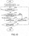
- FIG. 10 is a flowchart for explaining an example of an operation by the controller 90 according to the present embodiment.
- the controller 90 performs an assist control mode (S101). That is, the controller 90 drives the motor 20 to generate a force to offset inadequacy of an operation force applied by the user, to assist the rotation of the rear wheel 13.
- the controller 90 receives a detection signal of the proximity sensor 72, and determines whether the user presses the support pad 14 (the load is applied to the support pad 14) based on the detection signal (S102).
- the proximity sensor 72 detects the support pad 14 (more specifically, the magnet 77 attached to the support pad 14), and outputs an on-signal.
- the proximity sensor 72 outputs an off-signal otherwise.
- the controller 90 determines that the user presses the support pad 14 when the detection signal is the on-signal, and determines that the user does not press the support pad 14 when the detection signal is the off-signal.
- Another sensor such as a load sensor may be used instead as described above.
- the controller 90 may determine whether the user touches the support pad 14 instead of determining whether the support pad 14 is pressed. In this case, the electrostatic sensor, or the pressure sensor may be used as described above.
- the controller 90 When determining that the user presses the support pad 14 (YES in S102), the controller 90 continues the assistance of the rotation of the rear wheel 13 without braking the rear wheel 13 (i.e., without activating the braking).
- the controller 90 determines whether the rollator 100 is placed on the flat surface or the inclined surface (S103). Specifically, the controller 90 identifies the detection signal received from the inclination sensor 119, determines that the rollator 100 is placed on the inclined surface when the detection signal indicates an inclination of a certain angle of more, and determines that the rollator 100 is placed on the flat surface when the detection signal indicates the inclination below the certain angle.
- the inclination may be a front-rear direction, a right-left direction or both of them.
- the controller 90 applies the rheostatic braking when determining that the rollator 100 is placed on the flat surface (S104). On the other hand, the controller 90 applies the reverse braking when determining that the rollator 100 is placed on the inclined surface (S105). The controller 90 determines whether to finish the assist control mode (S106).
- the user may input an instruction for turning off the power source to the operation panel 83.
- the user may input an instruction for completing the assist control mode to the adjustment panel 84.
- the assist control mode may be forcibly finished.
- the assist control mode is finished (YES)
- this process ends. Note that when the assist control mode is forcibly finished in a state in which the reverse braking is applied, the controller 90 may control to automatically apply the mechanical braking.
- the state in which the braking is applied is kept while the off-signal is received from the proximity sensor 72 (until the on-signal is received). Note that when the rollator 100 is moved to the inclined surface in the state in which the rheostatic braking is applied, the controller 90 changes the braking to be used to the reverse braking ("inclined surface" in S103, 5105).
- the controller 90 determines that detection signal of the proximity sensor 72 is changed to the on-signal in the state in which the braking is applied (YES in S102), i.e., the user uses the rollator 100 for walking (the user is walking using the rollator 100, or the user attempts to walk using the rollator 100), the controller 90 stops the braking of the rear wheel 13 (releases the braking) and continues the assistance of the rotation of the rear wheel 13.
- the rheostatic braking may be used regardless of the magnitude of the inclination of the rollator 100.
- the mechanical braking for example, the rheostatic braking may be used even in the inclined surface. This can effectively prevent the motor from seizing up due to overcurrent by the reverse braking when the mechanical braking is applied. Even when the braking force of the mechanical braking is weak, the braking force can be obtained from the rheostatic braking.
- the rollator 100 can be effectively prevented from being automatically moved by automatically activating braking (i.e., applying the braking) in the state in which the user is separated from the support pad 14. Therefore, the user can use the rollator 100 with confidence.
- the controller 90 can detect that the user applied the load to the support pad 14 to grasp the user uses the rollator 100 for walking (the user attempts to walk or is walking). In this case, the controller 90 releases the braking, or keeps the release of the braking. Therefore, the user can walk using the rollator 100.
- the controller 90 detects that the user uses the rollator 100 for walking based on the distance to the support pad 14 from the detector. Therefore, the user can sensuously inform to the rollator 100 that the user uses the rollator 100 for walking.
- the support pad 14 is held at a position for activating the braking (brake activation position) by the spring (energization member) 74.
- the rollator 100 can be effectively prevented from being moved in the state in which the load against the spring 74 is not applied by the user. Therefore, the user can use the rollator 100 at ease.
- the user uses the rollator 100 for walking, the user leans on the support pad 14, and applies the load (the weight).
- the force against the spring 74 is generated, so that the support pad 14 can move the brake activation position. Therefore, the braking is released, so that the user can walk using the rollator 100.
- the load is not applied to the support pad 14 when the support pad 14 is flipped up (retracted position)
- the state in which the braking is performed is kept.
- the rollator 100 can be effectively prevented from being moved. Therefore, the user can sit on the seat 37 of the rollator 100 at ease.
- the proximity sensor 72 installed in the support frame 21 and the magnet (object to be detected) 77 installed in the support pad 14 are used.
- the support pad 14 is moved, the magnet 77 approaches the proximity sensor 72, and the proximity sensor 72 detects the magnet 77 (i.e., support pad 14).
- the proximity sensor 72 is installed in the body frame, the wire connecting between the proximity sensor 72 and the controller 90 can be housed in the body frame. Thereby, the wire is bundled with the brake wire and the brake sensor harness to simplify the wiring.
- the proximity sensor 72 is completely housed inside the frame, thereby capable of preventing the breakage caused by a physical external force, and easily maintaining waterproof and dustproof.
- the proximity sensor 72 is disposed in a position where the proximity sensor 72 does not detect the magnet 77 when the support pad 14 is in a brake activation position. Thereby, misdetection is effectively prevented.
- the controller 90 determines whether the rollator 100 is located on either the flat surface or the inclined surface based on inclination information of the rollator 100, and switches the type of the braking to be used between the rheostatic braking and the reverse braking.
- the rheostatic braking is selected, thereby reducing the power consumption.
- the reverse braking is selected to surely stop the rollator 100 at the current location.
- the mechanical braking may be selected instead of the rheostatic braking or the reverse braking.
- the rheostatic braking is used regardless of the magnitude of the inclination of the rollator 100 (even when the rollator 100 is placed on the inclined surface). This can effectively prevent the motor from seizing up due to overcurrent by the reverse braking when the mechanical braking is applied. Even when the braking force of the mechanical braking is weak, the braking force can be obtained from the rheostatic braking.
Landscapes
- Health & Medical Sciences (AREA)
- Epidemiology (AREA)
- Pain & Pain Management (AREA)
- Physical Education & Sports Medicine (AREA)
- Rehabilitation Therapy (AREA)
- Life Sciences & Earth Sciences (AREA)
- Animal Behavior & Ethology (AREA)
- General Health & Medical Sciences (AREA)
- Public Health (AREA)
- Veterinary Medicine (AREA)
- Rehabilitation Tools (AREA)
- Electric Propulsion And Braking For Vehicles (AREA)
- Regulating Braking Force (AREA)
Abstract
Description
- The present disclosure relates to an electric vehicle, a method of controlling the electric vehicle, a computer program, and an electric rollator.
- There has been known an electric vehicle called a rollator equipped with an electric motor to assist the elderly and people with reduced walking ability in walking. Such an electric vehicle is also called an electric rollator. The electric rollator is used for moving together with a walking person (user) when the user walks, and drives the motors of wheels to generate a force to offset inadequacy of an operation force applied by the user. Thus, the electric rollator assists walking of the user. The user with reduced walking ability can easily walk using the force generated by the electric rollator.
- It is preferable that the electric rollator does not start to move against a user's intention (e.g., malfunction). For example, the electric rollator is also used as a seat for the user when the user goes outside. It is preferable that a vehicle body stops before the user sits thereon and stays still when the user sits thereon. It is preferable that the electric rollator does not go down a slope even when the user releases both hands from the electric rollator for some reason when the electric rollator travels downhill.
- According to the present invention, provided is the electric rollator which does not move against a user's intention.
- According to one aspect of the present invention, the electric vehicle includes a detector (72) which detects a load applied by a part of a body of a user to a body supporter (14), or contact between the body of the user and the body supporter and generates a detection signal; and a controller (90) which controls braking of a wheel (12 or 13) or a continuous track based on the detection signal.
- In the electric vehicle, the load applied to the body supporter may be a load applied by the user in a direction perpendicular to a surface on which the electric vehicle is placed.
- In the electric vehicle, the body supporter may be relatively movable according to the load applied thereto with respect to a body frame including the detector. The detection signal may include information specifying a distance between the body supporter and the detector, or information whether the distance is a certain value or less. The controller may release the braking when the distance is the certain value or less, and perform the braking when the distance is not the certain value or less.
- In the electric vehicle, an energization member may is arranged between the body supporter and the body frame, which energizes the body supporter in a direction away from the body frame.
- In the electric vehicle, the detector may be a proximity sensor arranged in the body frame, the body supporter may be provided with an object capable of being detected by the proximity sensor, and the controller may release the braking when the proximity sensor detects the object, and perform the braking when the proximity sensor does not detect the object.
- In the electric vehicle, the body supporter may prevent the user from sitting on a seat of the electric vehicle when the body supporter is in a normal position, and permit the user to sit on the seat when the body supporter is in a retracted position different from the normal position.
- In the electric vehicle, the controller may detect an inclination of the electric vehicle, and switch a type of the braking according to the inclination.
- In the electric vehicle, the controller may perform reverse braking when a magnitude of the inclination of the electric vehicle is a certain value or more, and perform rheostatic braking when the magnitude of the inclination of the electric vehicle is smaller than the certain value.
- In the electric vehicle, the controller may perform rheostatic braking when mechanical braking is performed.
- According to one aspect, a method of controlling an electric vehicle includes: detecting a load applied by a part of a body of a user to a body supporter, or contact between the body of the user and the body supporter, and generating a detection signal; and controlling braking of a wheel or a continuous track based on the detection signal.
- According to one aspect, a computer readable medium stores therein a computer program causing a computer to execute: receiving a detection signal depending on a load applied by a part of a body of a user to a body supporter (14), or depending on contact between the body of the user and the body supporter; and controlling braking of a wheel or a continuous track based on the detection signal.
- According to one aspect, an electric rollator includes: a body frame provided with a wheel; a body supporter supporting a part of a body of a user, which is relatively movable according to a load applied thereto by the user with respect to the body frame; a detector provided in the body frame, which generates a detection signal depending on a distance between the body supporter and the detector; and a controller which controls braking of the wheel based on the detection signal, and which releases the braking when the distance is a certain value or less, and performs the braking when the distance is not the certain value or less.
-
-
FIG. 1 is a perspective view schematically illustrating an electric rollator as one example of an electric vehicle according to a certain example; -
FIG. 2 is a side view of the rollator inFIG. 1 ; -
FIG. 3 is a side view illustrating the rollator with a support pad flipped up; -
FIG. 4 is a diagram illustrating a detailed configuration of a detection mechanism that is provided between the support pad and a handle; -
FIG. 5 is a graph showing an example of a detection signal of a proximity sensor; -
FIG. 6 is a diagram illustrating an example of a control system mounted on the rollator inFIG. 1 and a peripheral configuration of the control system; -
FIG. 7 (A) and (B) each is a diagram illustrating an example of braking control depending on a magnitude of inclination of the rollator; -
FIG. 8 is a diagram illustrating another configuration example of a detection mechanism; -
FIG. 9 is a graph showing an example of differentiating three states of the rollator using a detection signal of a sensor; and -
FIG. 10 is a flowchart for explaining an operation by a controller according to a certain example. - Hereinafter, embodiments will be described with reference to the drawings. In the following description, like components are numbered similarly, and thus the descriptions thereof are omitted.
-
FIG. 1 is a perspective view schematically illustrating an electric rollator (hereinafter referred to as a rollator) 100 as one example of an electric vehicle according to an embodiment.FIG. 2 is a side view of therollator 100 inFIG. 1 . - As illustrated in
FIG. 1 andFIG. 2 , therollator 100 includes abody frame 11, a pair offront wheels 12 and a pair ofrear wheels 13 that are provided to thebody frame 11, and a support pad (body supporter) 14 that is provided to thebody frame 11. Therollator 100 is used to assist walking of the elderly and people with reduced walking ability. When using therollator 100, the user places the forearms or the elbows on thesupport pad 14 to apply a user's weight (load) to thesupport pad 14, and performs walking operation while gripping ahandle bar 15 and abrake lever 16. Therollator 100 drivesmotors 20 connected torear wheels 13 to generate a force to offset inadequacy of a force applied by the user so that therollator 100 can autonomously travel, thereby performing a walking assist control. A control system (seeFIG. 6 described later) for performing such an assist control is mounted on therollator 100 inFIG. 1 . Hereinafter, therollator 100 inFIG. 1 will be further described in detail. - The
body frame 11 is provided with a pair ofsupport frames 21 inclined by a predetermined angle from a direction perpendicular to a surface (e.g., ground surface) on which therollator 100 is placed. Thesupport frame 21 is made of a pipe-shaped member, as an example. A pair oflower frames 51 are horizontally disposed at lower ends of thesupport frames 21, respectively. A pair offront wheels 12 is attached to front ends of thelower frames 51, respectively. A pair oflink mechanisms 55 is provided to rear end side of thelower frames 51. - A pair of
upper frames 54 is disposed above the pair oflower frames 51, respectively. One ends of a pair ofrear wheel frames 57 are rotatably coupled to rear ends of the pair ofupper frames 54, respectively, through ashaft 56. At the other ends of the pair ofrear wheel frames 57, the pair ofrear wheels 13 are provided respectively. A pair ofmotors 20 to drive the respective correspondingrear wheels 13 is connected to the pair ofrear wheels 13. Themotor 20 used may be any motor such as a servomotor, a stepping motor, an AC motor, or a DC motor. Moreover, a motor integrally formed with a reducer may be used. - A pair of
handles 24 is provided on upper ends of the pair ofsupport frames 21, respectively. The pair ofhandles 24 are substantially horizontally disposed with respect to the surface on which therollator 100 is placed, and are made of a pipe-shaped member, as an example. Grips 23 (seeFIG. 2 ) that the user grips are provided at the pair ofhandles 24, respectively, so that the user can stabilize the posture of the user when the user sits. The pipe-shaped handle bar 15 is formed at front sides of the pair ofhandles 24 to integrate with thehandles 24. One end of thehandle bar 15 is connected to one of the pair ofhandles 24, and the other end of thehandle bar 15 is connected to the other of thehandles 24. Note that thehandle bar 15 may be made of a material different from the material of thehandles 24. - A pair of brake shoes 25 (not illustrated in
FIG. 1 , but illustrated inFIG. 2 ) are provided on outer peripheries of the pair ofrear wheels 13, respectively, such that they can be mechanically brought into contact with therear wheels 13. Thebrake shoes 25 are connected to one ends of brake wires (hereinafter referred to as wires) disposed in thebody frame 11, and the other ends of the wires are connected to wire connection mechanisms of a pair ofbrake units 61 that are provided on both sides of thehandle bar 15, respectively. Note that the wires are stored in thebody frame 11, but may be arranged outside the body frame to be apparently visible from the user. - A
brake lever 16 is disposed in a front lower direction of thehandle bar 15 to face thehandle bar 15. The pair ofbrake units 61 is connected to both ends of thebrake lever 16, respectively. The both ends of thebrake lever 16 are attached to thebrake units 61, respectively, through energizers such as coil springs. The user pulls thebrake lever 16 toward the user (in a direction of an arrow R1 inFIG. 2 ), thereby applying the mechanical braking using wire action. That is, the operation of thebrake lever 16 enables thebrake shoes 25 to be controlled. - For example, the user pulls the
brake lever 16 toward the user (in a direction of approaching the handle bar 15) to reach a brake activation position. Thebrake shoes 25 are moved by the action of the wires connected to thebrake lever 16 to then be pressed against the outer peripheries of therear wheels 13. Thus, the mechanical braking is applied. When the user releases the hands from thebrake lever 16, thebrake lever 16 is returned to an original position (normal position). Then, thebrake shoes 25 are also released from therear wheels 13 to release the mechanical braking. Thebrake lever 16 can be also moved in a direction opposite to the arrow R1 (downward direction). When thebrake lever 16 is moved downward to the parking position, the parking brake is applied to maintain a state in which thebrake shoes 25 are pressed against therear wheels 13 using the wire action. Thebrake lever 16 may be electrically connected to a user IF substrate (seeFIG. 6 ) through a wire in thebody frame 11. In this case, a brake switch is attached to thebrake lever 16 or thebrake unit 61, to be capable of notifying a state of the brake lever 16 (position of thebrake lever 16 such as the normal position, the brake activation position, or the parking position) to the user IF substrate. - The
support pad 14 is mounted above the pair ofhandles 24 to cover over the pair ofhandles 24. Thesupport pad 14 is a form of a body supporter for supporting a part of the body of the user. In the present embodiment, it is assumed that the forearms, the elbows, or both of them of the user are supported on thesupport pad 14. Note that a using form for supporting another portion such as a jaw, hands, or a chest may be applied. - A
detection mechanism 71 is provided between thehandles 24 and thesupport pad 14, to detect whether the user uses therollator 100 for walking. Specifically, thedetection mechanism 71 detects whether a load (weight) of the user is applied to thesupport pad 14, or whether the user is in contact with thesupport pad 14. The detail of thedetection mechanism 71 will be described later. Thesupport pad 14 has a horseshoe shape, as an example, but thesupport pad 14 is not limited to this shape, and may be any other shape. Thesupport pad 14 is configured by placing a cushion material such as a sponge or a rubber material on a plate material such as a wood plate, or a resin plate to be covered with any coating material made of resin or cloth, as an example. However, thesupport pad 14 is not limited to this configuration, and may have any other configuration. - One ends of a pair of
arm members 26 are fixed to both right and left sides of a bottom surface of thesupport pad 14. The other ends of the pair ofarm members 26 are rotatably attached to the outer sides of the pair ofhandle bar 15, respectively. When the user pushes up (flips up) thesupport pad 14 upwardly, thesupport pad 14 is rotated in a direction of an arrow R2 inFIG. 2 to be fixed at a predetermined position (retracted position).FIG. 3 illustrates a state of thesupport pad 14 after being rotated. A space for housing an upper body of the user can be formed above aseat 37. In this state, the user can turn the user's back toward thesupport pad 14 while gripping the pair ofgrips 23 with both hands, and sit on theseat 37. The user can stabilize the posture of the user by gripping thegrips 23 when the user sits on theseat 37. Thus, thesupport pad 14 prevents the user from sitting on theseat 37 of the rollator at a position before being flipped up (normal position), and allows the user to sit on theseat 37 at a position after being flipped up (retracted position). - Here, the
support pad 14 is configured to be manually flipped up by the user, but a lock mechanism (not illustrated) may be provided to release the fixing of thesupport pad 14, and thereby automatically flip up thesupport pad 14, as another example. Alternatively, an electric mechanism (a motor, or the like) for rotating thearm members 26 is provided to perform the electric mechanism by switch activation, and thereby flip up thesupport pad 14. - A storage 27 (see
FIG. 2 ) is provided between the pair ofupper frames 54 such that thestorage 27 is hung from the pair ofupper frames 54. Thestorage 27 has a bag shape with an upward opening. Thestorage 27 may be made of resin or cloth. The above-describedseat 37 for sitting is provided as a lid for thestorage 27. The control system (seeFIG. 6 ) described later is installed in thestorage 27, the control system including amain control substrate 81, a user IFsubstrate 82, abattery 87, aspeaker 85, and the like. - A
lever 28 is provided at a rear side of thestorage 27, thelever 28 extending downwardly from the pair ofupper frames 54. Thelever 28 is disposed at a position where the user can press down thelever 28 with the user's foot. By moving thelever 28 downwardly, the pair of rear wheel frames 57 and the pair ofrear wheels 13 are brought close to the pair offront wheels 12, resulting in that thelink mechanisms 55 are folded up. In this manner, therollator 100 can be folded up. -
FIG. 4 is a diagram illustrating a detailed configuration of thedetection mechanism 71. An upper portion ofFIG. 4 illustrates a state in which the user does not apply a load to thesupport pad 14. A lower portion ofFIG. 4 illustrates a state in which the user applies a load to thesupport pad 14. - As illustrated in the upper portion of
FIG. 4 , a proximity sensor (detector) 72 that detects a magnet (object to be detected) 77 is fixed and installed in onehandle 24 of the pair ofhandles 24. Theproximity sensor 72 can detect themagnet 77 without physically contacting themagnet 77. Theproximity sensor 72 is connected to the user IF substrate (seeFIG. 6 ) described later through a wire in thebody frame 11. A hall IC, etc. can be used as theproximity sensor 72, for example, the hall IC outputting an on (high-level or conductive) signal in a strength of a magnetic field being a certain value (threshold) or more, and an off (low-level or insulating) signal in a strength of a magnetic field being less than the certain value, but theproximity sensor 72 is not limited thereto. The relationship between the on signal and the off signal may be reversed: however, the configuration that the conductive signal is output in the strength of the magnetic field being the certain value or more is safe because the braking is applied when the signal line is disconnected. Note that the positional relationship between the magnet and the proximity sensor may be reversed. - A pair of
support members 73 is attached to both right and left lower sides of thesupport pad 14 to extend in a front-rear direction (a right-left direction along a plane ofFIG. 4 ). A width of thesupport member 73 in the right-left direction (a direction perpendicular to the plane ofFIG. 4 ) is about the same as that of thehandle 24 or thegrip 23, or is slightly wider or narrower than thehandle 24 or thegrip 23, but is not limited thereto. Thesupport member 73 is moved downwardly when the load is applied to thesupport pad 14 by the user (e.g., when the load is applied in the direction perpendicular to the the surface on which therollator 100 is placed), and thesupport member 73 is pressed against the handle 24 (including the grip 23). Thesupport pad 14 stops at a position corresponding to the thickness of thesupport member 73. - A gap is formed to vertically penetrate the inside at the front end side of each of the pair of
support members 73. A spring (energization member) 74 having an energization force in the vertical direction is disposed in the gap. A type of thespring 74 is a coil spring, as an example, but may have any other configuration. The energization member other than the spring may be used. An upper portion of thespring 74 is fixed to thesupport pad 14 through anyprotection member 75. A lower portion of thespring 74 is covered with acap 76. The lower portion of thespring 74 protrudes from the bottom surface of thesupport member 73 in a state in which the load is not applied to thesupport pad 14, and is in contact with a top surface of thehandle 24 through thecap 76. When the load is applied to thesupport pad 14 in this state, thespring 74 is compressed, and the portion protruding from the bottom surface of thesupport member 73 is housed in the gap in thesupport member 73, so that thesupport pad 14 is moved toward thehandle 24 side, and the bottom surface of thesupport member 73 is pressed against thehandle 24 and thegrip 23. Note that thecap 76 and theprotection member 75 are made of resin as an example, but the materials of thecap 76 and theprotection member 75 are not limited thereto. - The
magnet 77 is installed inside one (the support member on the same side as the handle in which theproximity sensor 72 is installed) of the pair ofsupport members 73. The shape of themagnet 77 may be rectangular, cylindrical, or any other shape. Themagnet 77 at least needs to be positioned so that theproximity sensor 72 cannot detect themagnet 77 in a state in which the load is not applied to thesupport pad 14, and theproximity sensor 72 can detect themagnet 77 in a state in which the load is applied to thesupport pad 14. If this condition is satisfied, the position of the magnet and the magnetic force can be arbitrary. However, since thesupport pad 14 may approach thehandle 24 due to vibration during traveling even when the load is not applied to thesupport pad 14, thedetection mechanism 71 needs to be configured to prevent theproximity sensor 72 from wrongly detecting themagnet 77 at this time. - Note that it is preferable that the magnetic force of the magnet be larger than the magnetic force of portable articles and personal ornaments normally used by the user. Thus, when the
proximity sensor 72 is in a range in which theproximity sensor 72 does not detect the magnet (e.g., in a state in which thesupport pad 14 is pulled up) and the user approaches theproximity sensor 72, theproximity sensor 72 can be prevented from misdetection. - Hereinafter, with reference to
FIG. 4 , the operation when the user applies the load to thesupport pad 14 will be described. As illustrated in the upper portion ofFIG. 4 , since the energization force of thespring 74 is larger than the weight of thesupport pad 14 before the user applies the load to thesupport pad 14, themagnet 77 and theproximity sensor 72 are separated from each other. In this state, theproximity sensor 72 does not detect themagnet 77, and generates and outputs the off (low level) detection signal. Similarly, theproximity sensor 72 does not detect themagnet 77 when thesupport pad 14 is flipped up (seeFIG. 3 ), and theproximity sensor 72 generates and outputs the off detection signal. - On the other hand, as illustrated in the lower portion of
FIG. 4 , since the total of the load applied by the user and the weight of thesupport pad 14 is larger than the energization force of thespring 74 when the user applies the load to thesupport pad 14, thespring 74 is compressed, and a distance between themagnet 77 and theproximity sensor 72 is reduced. When the distance from themagnet 77 is a certain value or less, i.e., when a movement amount of the magnet 77 (i.e., a movement amount of the support pad 14) is a certain value or more, theproximity sensor 72 detects the magnet 77 (i.e., support pad 14). Theproximity sensor 72 generates and outputs the on (high level) detection signal when detecting themagnet 77. - The detection signal of the
proximity sensor 72 is input to the user IF substrate (seeFIG. 6 ) described later through a wire (not illustrated). -
FIG. 5 is a graph showing an example of detection signal of the proximity sensor. At a time t0, the detection signal of theproximity sensor 72 is an on (high level) signal in a state in which the load is applied to thesupport pad 14. At a time t1 after the time t0, the detection signal of theproximity sensor 72 is changed to an off (low level) signal in a state in which the user is separated from thesupport pad 14, and the load is not applied to thesupport pad 14. - The controller (see
FIG. 6 described later) in the present embodiment controls braking such as activation and release of the braking in accordance with the detection signal (output signal) as one of characteristics of the present embodiment. The details will be described later. -
FIG. 6 is a diagram illustrating an example of the control system that is mounted in therollator 100 and a peripheral configuration of the control system. The control system inFIG. 6 includes amain control substrate 81, a user IF (InterFace)substrate 82, anoperation panel 83, andadjustment panel 84, aspeaker 85, abattery 87, and motors 20 (a right motor, a left motor). Themotors 20 correspond to themotors 20 illustrated inFIG. 1 , respectively. Themain control substrate 81, the user IFsubstrate 82, thespeaker 85, and thebattery 87 are disposed in thestorage 27, as an example, but they may be partially or wholly disposed in another place. Themain control substrate 81, the user IFsubstrate 82, or both of them may be provided with a clock (not illustrated). - The
battery 87 is used to supply electric power to each element of themotors 20, themain control substrate 81, and the user IFsubstrate 82. Thebattery 87 is a battery (secondary battery) capable of charging and discharging, but is not limited thereto. - The
operation panel 83 is a panel used for manually setting by the user such as on/off for a power source of therollator 100, a voice volume, and the like. Theadjustment panel 84 is a panel for setting of on/off for an assist control mode, adjusting the maximum speed, adjusting the strength of the braking. Theoperation panel 83 and theadjustment panel 84 are configured with liquid crystal touch panels, as an example, but may have any other configuration such as a button-type panel. Theoperation panel 83 and theadjustment panel 84 are provided at arbitrary positions (positions where the user can easily operate the panels) of therollator 100. A unit for setting off theproximity sensor 72 may be provided to theoperation panel 83. Theproximity sensor 72 may be set off in a state in which thesupport pad 14 is flipped up, to perform the assist control. - The user IF
substrate 82 is connected to theadjustment panel 84, theoperation panel 83, themain control substrate 81, the brake switch (brake SW) 86, the proximity sensor (pad switch) 72, and thespeaker 85 through respective IFs. When detecting that the user has performed the brake operation or the parking brake operation with thebrake lever 16, thebrake switch 86 outputs a signal for notifying the operation. When detecting the magnet 77 (i.e., detecting that thesupport pad 14 has been pressed), theproximity sensor 72 outputs an on-signal, and outputs an off-signal otherwise. A lamp indicating that the brake operation or the parking brake operation has performed may be provided to theoperation panel 83 or theadjustment panel 84. A lamp for notifying that thesupport pad 14 is pressed may be provided to theoperation panel 83 or theadjustment panel 84. - The user IF
substrate 82 transmits, to themain control substrate 81, signals input from theproximity sensor 72, thebrake SW 86, theadjustment panel 84, and theoperation panel 83. The user IF substrate is also provided with thevoice guide 89, and thevoice guide 89 generates a voice guide signal based on signals input from theproximity sensor 72, thebrake SW 86, theadjustment panel 84, and theoperation panel 83, or based on a signal input from themain control substrate 81, and outputs it to thespeaker 85. Thespeaker 85 outputs a voice based on the input signal. When the user turns on the power source, for example, thespeaker 85 outputs a voice message that "the power source has been turned on." If thebrake lever 16 is not moved downwardly (the parking brake is not applied) in a state in which therollator 100 stops or the load is not applied to thesupport pad 14 for a certain time, thespeaker 85 outputs a voice message prompting the user to apply the parking brake such as "please lower the brake lever.". Alternatively, an LED mounted on theoperation panel 83 may be used to visually display the warning. - The
main control substrate 81 includes acontroller 90 for performing the entire control. Thecontroller 90 is a program execution and arithmetic device such as a microcomputer, a processor, or a CPU. In the present embodiment, thecontroller 90 is a microcomputer. Anon-volatile memory 91 stores a program code for operating thecontroller 90, information or data generated by thecontroller 90, information or data required to operate thecontroller 90, information or data received from the other elements, and the like. Thecontroller 90 reads out and executes the program code in thenon-volatile memory 91 to perform the control. Thenon-volatile memory 91 may be any memory such as a flash memory (a NAND memory, etc.), an MRAM, or an FRAM. Thecontroller 90 may be not a program execution device, but a device such as an application specific integrated circuit (ASIC), or a field programmable gate array (FPGA). - The
controller 90 calculates the state (posture, etc.) of therollator 100 using anacceleration sensor 92. As theacceleration sensor 92, one or more of uniaxial, biaxial, and triaxial sensors may be used. A gyro sensor may be used instead of theacceleration sensor 92. Thecontroller 90 specifies the state of the right motor 20 (e.g., rotation position, speed, the number of revolutions and the like of a rotor or a motor shaft) based on a signal of the hall IC incorporated in theright motor 20. Thecontroller 90 specifies the state of theleft motor 20 based on a signal of the hall IC incorporated in theleft motor 20. Thecontroller 90 controls (performs an assist control) the drive of both right and leftmotors 20 using these pieces of information to compensate a force to offset inadequacy of a force applied by the user. - The
controller 90 performs braking control based on a detection signal of theproximity sensor 72. Specifically, thecontroller 90 releases the braking when the detection signal is an on-signal (when the load is applied to the support pad 14), and thecontroller 90 controls to perform the braking when the detection signal is an off-signal (when the load is not applied to the support pad 14). Examples of the types of brake include a rheostatic braking, and a reverse braking. The type of brake to be used can be preliminarily determined or selected according to a situation (inclination of the rollator) as described later. - The RHEOSTATIC braking is short-circuited among U, V, W phases of the motor 20 (normal drive is stopped), and obtains a braking force using a counter electromotive force generated by the rotation of the
motor 20. Instead of the rheostatic braking, regenerative braking can be employed. As characteristics of the rheostatic braking, the smooth braking can be assured. Especially, in the case of regenerative braking, the electric power can be regenerated. But therollator 100 cannot be completely stopped, and the breaking force is weak. - The reverse braking drives the motor backwardly when the wheels are moved in the forward direction, and drives the motor forwardly when the wheels are moved in the backward direction, so that the rollator body is stopped at the current location (i.e., immediately). As characteristics of the reverse braking, the braking force is strong, and the rollator body can be stopped at the current location, but the power consumption is large, and the vibration is caused.
- The
controller 90 may control to switch between the rheostatic braking and the reverse braking using the information on inclination of therollator 100. The inclination of therollator 100 can be detected using aninclination sensor 119, as an example. Theinclination sensor 119 measures the inclination of the rollator body, and outputs a signal indicating the measured inclination as a detection signal. -
FIGS. 7(A) and 7(B) each is a diagram illustrating an example of braking control using the information on the inclination of therollator 100. As illustrated inFIG. 7(A) , thecontroller 90 determines that the rollator body is placed on an inclined surface (slope, etc.) when a detection signal of theinclination sensor 119 indicates that the inclination angle is a certain angle or more. In this case, thecontroller 90 selects the reverse braking. On the other hand, as illustrated inFIG. 7(B) , thecontroller 90 determines that the rollator body is placed on a flat surface (flatland) when the detection signal of theinclination sensor 119 indicates that the inclination angle is below the certain angle. In this case, thecontroller 90 selects the rheostatic braking. - In other words, on the flat surface such as a flatland, the rollator body can be stopped even by the rheostatic braking. When the user sits on the
seat 37 for a long time, the use of the reverse braking causes increase in consumption power, but the use of the rheostatic braking with small power consumption saves the power consumption. Therefore, it is desirable to select the rheostatic braking on the flat surface. On the other hand, on the inclined surface such as a slope, there is a risk that the rollator body may travel down the slope if the reverse braking is not selected. Therefore, it is desirable to select the reverse braking on the inclined surface. - Note that the other brake that can stop the rollator body at the current location may be applied instead of the rheostatic braking or the reverse braking. As an example of the other brake, there is the mechanical braking using the
brake shoe 25. - The
controller 90 may be configured to control the mechanical braking, or the rheostatic braking or the reverse braking using a signal from a brake switch. - In the present embodiment, the
inclination sensor 119 is used to measure the inclination of therollator 100, but theacceleration sensor 92 may be used to calculate the inclination of therollator 100. In this case, theacceleration sensor 92 measures gravity acceleration to calculate the inclination. Accordingly, the acceleration sensor is one kind of the inclination sensor. - In the configuration of
FIG. 6 , there are two substrates of themain control substrate 81 and the user IFsubstrate 82, but components mounted in these substrates may be collectively mounted in one substrate. A communication circuit that wiredly or wirelessly communicates in a predetermined communication scheme may be provided in themain control substrate 81 or the user IFsubstrate 82 to be communicable with an external device. The state of the rollator may be notified to the external device through communication, and the program in thenon-volatile memory 91 may be updated by obtaining the update data from the external device. A threshold for controlling on/off of theproximity sensor 72 can be adjusted through communication. Examples of the states of therollator 100 to be notified to the external device include a current position using a GPS (Global Positioning System), etc., and presence/absence of an occurrence of fault in therollator 100, but are not limited thereto. For example, the communication circuit may notify information for differentiating among a plurality of states: the state in which the load is applied to thesupport pad 14, the state in which the load is not applied to thesupport pad 14, and the state in which thesupport pad 14 is flipped up. - In the present embodiment, the
motor 20 is attached to each of therear wheels 13, but the attachment of themotor 20 is not limited to therear wheel 13, and themotor 20 may be attached only to each of the pair offront wheels 12. Alternatively, themotors 20 may be attached to all of the pair offront wheels 12 and the pair ofrear wheels 13. Themotor 20 has been used a brake of the wheel (rear wheel 13) in the description explained previously, but another brake for the wheel may be provided separately from themotor 20; the mechanical brake or an electromagnetic brake. - The present embodiment has been described using an example in which the pair of rear wheels (wheels) 13 are driven by the
motor 20, but is not limited thereto, and a continuous track in which a continuous band of track plates surrounds starting wheels, rollers, and idling wheels (guide wheels) may be driven by the motor. In this case, the continuous track is to be braked. - In the present embodiment, the
proximity sensor 72 is disposed in one of the pair ofhandles 24, and themagnet 77 is disposed in thesupport member 73 facing the one of the pair ofhandles 24 in which theproximity sensor 72 is disposed; however, theproximity sensors 72 may be disposed in both of the pair ofhandles 24, respectively, and themagnets 77 may be disposed in the pair ofsupport members 73, respectively. - In the present embodiment, the
proximity sensor 72 and themagnet 77 are used to detect that thesupport pad 14 approaches thehandle 24, but a magnetic sensor and a magnet may be used to detect it. A metal such as copper may be used as an object to be detected instead of the magnet. In this case, the proximity sensor for the metal is used as the detector. A distance measurement sensor that outputs a signal according to a distance between the distance measurement sensor and the support pad 14 (a signal according to the movement amount of the support pad 14) may be used as the detector, and in this case, the object to be detected such as a magnet or a metal is not required. An infrared sensor or an ultrasonic wave sensor may be used as an example of the distance measurement sensor. The distance measurement sensor outputs an on signal when a distance from the target (e.g., support pad 14) is a certain value or less. A limit sensor may be used as the detector instead of the distance measurement sensor. In this case, thesupport pad 14 approaches the limit sensor to push a switch of the limit sensor, so that the limit sensor is turned on, and outputs the on signal. Various modifications are possible to enhance the detection sensitivity of the sensor according to the type of sensor to be used such as a proximity sensor, a magnetic sensor, or a distance measurement sensor. For example, a gap may be formed in a handle surface facing the sensor, or a material different from that of the handle may be used for this handle surface. - The present embodiment is configured to move the
support pad 14 downwardly (a direction perpendicular to the surface on which therollator 100 is placed) by applying the load to thesupport pad 14 when the rollator is used, but may be configured to fixedly arrange thesupport pad 14 so that the position of thesupport pad 14 is not moved even when the load is applied to thesupport pad 14. In this case, a load sensor or a strain sensor may be used as the detector instead of the proximity sensor or the distance measurement sensor. The load sensor or the strain sensor may be provided in thesupport pad 14, or may be attached to thehandle 24 or the frame such as thesupport frame 21. The type of the load sensor to be used can be arbitrary if the load sensor can distinguish between the weight of thesupport pad 14 itself and the total of the load by the user and the weight of thesupport pad 14. The type of the load sensor may be an electrostatic capacitance type or a strain gauge type. In either of both types, thecontroller 90 can determine that the load is applied to the support pad 14 (the user uses the rollator for walking) if the detected value is the threshold or more, or below the threshold. - The sensor may detect whether the user touches the
support pad 14 to specify whether the user uses therollator 100 for walking. When the user sits on the seat, for example, the user does not touch thesupport pad 14. Then, it is determined that the user does not use the rollator for walking. An electrostatic sensor, a piezoelectric sensor, or a pressure sensor may be used as an example of the detector to detect the presence/absence of contact with thesupport pad 14 by the user. By using at least any sensor of these sensors, the sensor can detect whether the user touches thesupport pad 14 based on variation in electrostatic capacitance or pressure. It is assumed that the sensor is installed within thesupport pad 14 which the user contacts with (presses) in walking; however, the sensor may be provided at any other position. - The sensor such as the proximity sensor used in the present embodiment outputs an on-signal (indicating that the distance or the load reaches a certain value) or an off-signal (indicating that the distance or the load does not reach the certain value) according the load applied to the
support pad 14 or the distance to thesupport pad 14. As another configuration, the sensor may detect a value (analog value) in a fixed range as a sensing value according to a physical amount (distance, weight, strain, pressure, etc.) measured by the sensor, and output a signal (voltage or current) indicating the detected value. In this case, the detected value is equivalent the load applied to thesupport pad 14 or the information specifying the distance to thesupport pad 14. Thecontroller 90 of themain control substrate 81 determines whether the user applied the load to the support pad 14 (the user uses therollator 100 for walking) based on a value of voltage or current indicated by the signal. When the voltage or current is a threshold or more (or below the threshold), for example, thecontroller 90 determines that the load is applied to the support pad 14 (the user uses therollator 100 for walking) to control to release the braking. On the other hand, when the voltage or current is below the threshold (or the threshold or more), thecontroller 90 determines that the load is not applied (the user does not use therollator 100 for walking), to control to perform the braking. - An inclination sensor or an acceleration sensor may be attached to the
support pad 14, thesupport member 73, or thearm member 26, or an angle sensor may be attached to a joint between thearm member 26 and thehandle bar 15. Thereby, it is possible to measure an angle between thehandle bar 15 and thesupport pad 14, thesupport member 73 or the arm member 26 (i.e., an angle between thehandle bar 15 and thesupport pad 14, an angle between thehandle bar 15 and thesupport member 73 or an angle between thehandle bar 15 and the arm member 26). In this case, the angle between thehandle bar 15 and thesupport pad 14, thesupport member 73 or thearm member 26 when the load is not applied to thesupport pad 14 is larger than that when the load is applied to thesupport pad 14. Therefore, based on this, the sensor can detect the presence/absence of the load. For example, thesupport pad 14 is substantially parallel to thehandle bar 15 when the load is applied to thesupport pad 14, but thesupport pad 14 has a certain angle or more with respect to thehandle bar 15 when the load is not applied to thesupport pad 14. Therefore, the sensor can detect the presence/absence of the load. Alternatively, the angle between thehandle bar 15 and thesupport pad 14, thesupport member 73 or thearm member 26 when the load is applied to thesupport pad 14 may be larger than that when the load is not applied to thesupport pad 14, depending on how to arrange thesupport pad 14, thesupport member 73 or thearm member 26. Also even in this case, the sensor can detect the presence/absence of the load similarly. - The
proximity sensor 72 and themagnet 77 may be disposed at positions different from those illustrated inFIG. 4 . The example is illustrated inFIG. 8 . A length of aconnection part 80 of thearm member 26 with thehandle bar 15 extends in a direction opposite to thearm member 26, and themagnet 79 is disposed at a side of one end of theconnection 80. Theproximity sensor 78 is disposed in thehandle bar 15 in the vicinity of themagnet 79. As illustrated in the upper portion ofFIG. 8 , since themagnet 79 and theproximity sensor 78 are separated by a certain distance when the load is not applied to thesupport pad 14, theproximity sensor 78 does not detect themagnet 79. As illustrated in the lower portion ofFIG. 8 , the one end of theconnection 80 is rotated to approach theproximity sensor 78 when the load is applied to thesupport pad 14, so that themagnet 79 approaches theproximity sensor 78, and then theproximity sensor 78 detects themagnet 79. The arrangement of themagnet 79 and theproximity sensor 78 may be reversed. As another configuration, the load sensor and a distance sensor may be used instead of themagnet 79 and theproximity sensor 78. For example, the distance sensor is disposed in the vicinity of the one end of theconnection 80, and a distance from a predetermined position (e.g., a predetermined portion of the handle bar 15) may be measured by the distance sensor. - The present embodiment has been described mainly using an example in which the sensor outputs an on-signal or an off-signal. Since as described above, the sensing value can be detected as an analog value depending on a type of the sensor, and based on this, not only binary signal (low level and high level) but also signal with more levels can be determined. Examples of the sensor include a magnetic sensor, a distance measurement sensor, and a load sensor. The
controller 90 can determine three states, i.e., a state in which the load is applied to thesupport pad 14, a state in which the user is separated from the support pad 14 (the user releases the hand from the support pad 14), and a state in which thesupport pad 14 is flipped up. For example, the sensor outputs a high-level signal if a sensing value is a threshold A or more as a detection signal, the sensor outputs a middle-level signal if the sensing value is below the threshold A and a threshold B or more as the detection signal, and the sensor outputs a low-level signal if the sensing value is below the threshold B. Thecontroller 90 determines that the load is applied to thesupport pad 14 if the high-level signal is output, determines that the user is separated from thesupport pad 14 if the middle-level signal is output, and determines that thesupport pad 14 is flipped up if the low-level signal is output. Note that thecontroller 90 may receive a signal of the sensing value from the sensor, and compare the sensing value with the threshold A, the threshold B, or both of the threshold A and the threshold B. -
FIG. 9 is a graph showing an example of a detection signal of a magnetic sensor when the magnetic sensor is used instead of theproximity sensor 72. If the distance measurement sensor or the load sensor is used, a similar graph is even obtained. At a time t2, the detection signal of the magnetic sensor is a high-level signal in a state in which the load is applied to thesupport pad 14. At a time t3, the detection signal of the magnetic sensor is changed to a middle-level signal in a state in which the user leaves from thesupport pad 14, and thesupport pad 14 containing themagnet 77 is separated from the magnetic sensor. Then, at a time t4, the detection signal is changed to a low-level signal in a state in which the user flips up thesupport pad 14 to sit on the seat, and themagnet 77 is further separated from the magnetic sensor. Identification of respective levels can be determined by properly determining the threshold A and the threshold B. Since according to this configuration, it can be distinguished when the user releases the hand from thesupport pad 14 and when the user sits on the seat, the reverse braking can be selected when the user releases the hand from thesupport pad 14, and the rheostatic braking can be selected when the user sits on the seat. At this time, information on whether the inclined surface or a flat surface may be used for further processing or may not be used. For example, when on the inclined surface, the user flips up thesupport pad 14 to sit on the seat, thespeaker 85 can warn the user to not sit on the seat on an inclined surface. - Here, an example in which the three states are differentiated using the magnetic sensor capable of detecting in analog value has been described, but the three states can be also differentiated using a plurality of proximity sensors having different detection levels. For example, in
FIG. 4 , another proximity sensor (hereinafter referred to as an auxiliary sensor) is disposed on thegrip 23 side relative to theproximity sensor 72, and another magnet (hereinafter referred to as an auxiliary magnet) is disposed in thesupport member 73 so that the auxiliary magnet faces the auxiliary sensor. In the state in which the load is not applied to thesupport pad 14, theproximity sensor 72 does not detect themagnet 77, but the auxiliary sensor detects the auxiliary magnet. In the state in which the load is applied to thesupport pad 14, theproximity sensor 72 detects themagnet 77, and the auxiliary sensor also detects the auxiliary magnet. In the state in which thesupport pad 14 is flipped up, theproximity sensor 72 does not detect themagnet 77, and the auxiliary sensor does not detect the auxiliary magnet. Therefore, the above-described three states can be differentiated using the detection signal of theproximity sensor 72 and the detection signal of the auxiliary sensor. The auxiliary sensor and the auxiliary magnet are not limited to the above-described example, and may be theproximity sensor 78 and themagnet 79 illustrated inFIG. 8 , for example. The three states can be also determined using a plurality of proximity sensors and one magnet without using the auxiliary magnet. At this time, there are two cases; (1) the plurality of proximity sensors having the same detection level are used, and (2) the plurality of proximity sensors having different detection levels are used. In the case (1), each proximity sensor is disposed (in a direction perpendicular to the surface on which the electric vehicle is placed, for example) so that distances between the magnet and the proximity sensors are different from each other. In the state in which the load is not applied to thesupport pad 14, one proximity sensor does not detect the magnet, and the other proximity sensor detects the magnet. In the state where in which the load is applied to thesupport pad 14, both of the proximity sensors detect the magnet. In the state in which thesupport pad 14 is flipped up, both of the proximity sensors do not detect the magnet. Therefore, the above-described three states can be differentiated using the detection signals of the plurality of proximity sensors. On the other hand, in the case (2), the proximity sensors may be disposed at any position as long as the following conditions are satisfied: one proximity sensor does not detect the magnet, and the other proximity sensor detects the magnet in the state in which the load is not applied to thesupport pad 14, both of the proximity sensors detect the magnet in the state in which the load is applied to thesupport pad 14, and both of the proximity sensors do not detect the magnet in the state in which thesupport pad 14 is flipped up. Therefore, the above-described three states can be differentiated using the detection signals of the plurality of proximity sensors. -
FIG. 10 is a flowchart for explaining an example of an operation by thecontroller 90 according to the present embodiment. - The
controller 90 performs an assist control mode (S101). That is, thecontroller 90 drives themotor 20 to generate a force to offset inadequacy of an operation force applied by the user, to assist the rotation of therear wheel 13. - The
controller 90 receives a detection signal of theproximity sensor 72, and determines whether the user presses the support pad 14 (the load is applied to the support pad 14) based on the detection signal (S102). When thesupport pad 14 is moved from a predetermined position by a certain distance or more, theproximity sensor 72 detects the support pad 14 (more specifically, themagnet 77 attached to the support pad 14), and outputs an on-signal. Theproximity sensor 72 outputs an off-signal otherwise. Thecontroller 90 determines that the user presses thesupport pad 14 when the detection signal is the on-signal, and determines that the user does not press thesupport pad 14 when the detection signal is the off-signal. Another sensor such as a load sensor may be used instead as described above. Thecontroller 90 may determine whether the user touches thesupport pad 14 instead of determining whether thesupport pad 14 is pressed. In this case, the electrostatic sensor, or the pressure sensor may be used as described above. - When determining that the user presses the support pad 14 (YES in S102), the
controller 90 continues the assistance of the rotation of therear wheel 13 without braking the rear wheel 13 (i.e., without activating the braking). - On the other hand, when determining that the user does not press the support pad 14 (NO in S102), the
controller 90 determines whether therollator 100 is placed on the flat surface or the inclined surface (S103). Specifically, thecontroller 90 identifies the detection signal received from theinclination sensor 119, determines that therollator 100 is placed on the inclined surface when the detection signal indicates an inclination of a certain angle of more, and determines that therollator 100 is placed on the flat surface when the detection signal indicates the inclination below the certain angle. The inclination may be a front-rear direction, a right-left direction or both of them. - The
controller 90 applies the rheostatic braking when determining that therollator 100 is placed on the flat surface (S104). On the other hand, thecontroller 90 applies the reverse braking when determining that therollator 100 is placed on the inclined surface (S105). Thecontroller 90 determines whether to finish the assist control mode (S106). - To finish the assist control mode, for example, the user may input an instruction for turning off the power source to the
operation panel 83. Alternatively, the user may input an instruction for completing the assist control mode to theadjustment panel 84. Alternatively, when the braking (the rheostatic braking or the reverse braking) is continuously applied for a certain time or more, the assist control mode may be forcibly finished. When the assist control mode is finished (YES), this process ends. Note that when the assist control mode is forcibly finished in a state in which the reverse braking is applied, thecontroller 90 may control to automatically apply the mechanical braking. - When the assist control mode is not finished (NO in S106), the state in which the braking is applied is kept while the off-signal is received from the proximity sensor 72 (until the on-signal is received). Note that when the
rollator 100 is moved to the inclined surface in the state in which the rheostatic braking is applied, thecontroller 90 changes the braking to be used to the reverse braking ("inclined surface" in S103, 5105). When thecontroller 90 determines that detection signal of theproximity sensor 72 is changed to the on-signal in the state in which the braking is applied (YES in S102), i.e., the user uses therollator 100 for walking (the user is walking using therollator 100, or the user attempts to walk using the rollator 100), thecontroller 90 stops the braking of the rear wheel 13 (releases the braking) and continues the assistance of the rotation of therear wheel 13. - Note that when the
brake lever 16 is moved downwardly to apply the mechanical braking, the rheostatic braking may be used regardless of the magnitude of the inclination of therollator 100. When the mechanical braking is applied, for example, the rheostatic braking may be used even in the inclined surface. This can effectively prevent the motor from seizing up due to overcurrent by the reverse braking when the mechanical braking is applied. Even when the braking force of the mechanical braking is weak, the braking force can be obtained from the rheostatic braking. - According to the present embodiment, the
rollator 100 can be effectively prevented from being automatically moved by automatically activating braking (i.e., applying the braking) in the state in which the user is separated from thesupport pad 14. Therefore, the user can use therollator 100 with confidence. - In the state in which the
rollator 100 is stopped or travels at a constant speed (note that the state in which therollator 100 is stopped is one example of the state in which therollator 100 travels at a constant speed), thecontroller 90 can detect that the user applied the load to thesupport pad 14 to grasp the user uses therollator 100 for walking (the user attempts to walk or is walking). In this case, thecontroller 90 releases the braking, or keeps the release of the braking. Therefore, the user can walk using therollator 100. - According to the present embodiment, the
controller 90 detects that the user uses therollator 100 for walking based on the distance to thesupport pad 14 from the detector. Therefore, the user can sensuously inform to therollator 100 that the user uses therollator 100 for walking. - According to the present embodiment, the
support pad 14 is held at a position for activating the braking (brake activation position) by the spring (energization member) 74. Thus, therollator 100 can be effectively prevented from being moved in the state in which the load against thespring 74 is not applied by the user. Therefore, the user can use therollator 100 at ease. When the user uses therollator 100 for walking, the user leans on thesupport pad 14, and applies the load (the weight). Thus, the force against thespring 74 is generated, so that thesupport pad 14 can move the brake activation position. Therefore, the braking is released, so that the user can walk using therollator 100. - According to the present embodiment, since the load is not applied to the
support pad 14 when thesupport pad 14 is flipped up (retracted position), the state in which the braking is performed is kept. Thus, therollator 100 can be effectively prevented from being moved. Therefore, the user can sit on theseat 37 of therollator 100 at ease. - According to the present embodiment, the
proximity sensor 72 installed in thesupport frame 21 and the magnet (object to be detected) 77 installed in thesupport pad 14 are used. When the user applied the load to thesupport pad 14, thesupport pad 14 is moved, themagnet 77 approaches theproximity sensor 72, and theproximity sensor 72 detects the magnet 77 (i.e., support pad 14). When theproximity sensor 72 is installed in the body frame, the wire connecting between theproximity sensor 72 and thecontroller 90 can be housed in the body frame. Thereby, the wire is bundled with the brake wire and the brake sensor harness to simplify the wiring. Theproximity sensor 72 is completely housed inside the frame, thereby capable of preventing the breakage caused by a physical external force, and easily maintaining waterproof and dustproof. Theproximity sensor 72 is disposed in a position where theproximity sensor 72 does not detect themagnet 77 when thesupport pad 14 is in a brake activation position. Thereby, misdetection is effectively prevented. - According to the present invention, the
controller 90 determines whether therollator 100 is located on either the flat surface or the inclined surface based on inclination information of therollator 100, and switches the type of the braking to be used between the rheostatic braking and the reverse braking. When therollator 100 is placed on the flat surface, the rheostatic braking is selected, thereby reducing the power consumption. When therollator 100 is placed on the inclined surface, the reverse braking is selected to surely stop therollator 100 at the current location. The mechanical braking may be selected instead of the rheostatic braking or the reverse braking. Thus, by using the inclination information of therollator 100, an appropriate brake can be selected according to the state of therollator 100. - According to the present embodiment, when the
brake lever 16 is moved downwardly to apply the mechanical braking, the rheostatic braking is used regardless of the magnitude of the inclination of the rollator 100 (even when therollator 100 is placed on the inclined surface). This can effectively prevent the motor from seizing up due to overcurrent by the reverse braking when the mechanical braking is applied. Even when the braking force of the mechanical braking is weak, the braking force can be obtained from the rheostatic braking. - While certain arrangements have been described, these arrangements have been presented by way of example only, and are not intended to limit the scope of the claims. The apparatuses described herein may be embodied in a variety of other forms; furthermore various omissions, substitutions and changes in the form of the apparatuses described herein may be made.
Claims (12)
- An electric vehicle comprising:a detector (72) which detects a load applied by a part of a body of a user to a body supporter (14) or detects contact between the body of the user and the body supporter, and generates a detection signal; anda controller (90) which controls braking of a wheel (12 or 13) or a continuous track based on the detection signal.
- The electric vehicle according to claim 1, wherein
the load applied to the body supporter (14) is a load applied by the user in a direction perpendicular to a surface on which the electric vehicle is placed. - The electric vehicle according to claim 1 or 2, wherein
the body supporter (14) is relatively movable according to the load applied thereto with respect to a body frame (11) including the detector,
the detection signal includes information specifying a distance between the body supporter (14) and the detector (72), or information whether the distance is a certain value or less, and
the controller (90) releases the braking when the distance is the certain value or less, and performs the braking when the distance is not the certain value or less. - The electric vehicle according to claim 3, further comprising:
an energization member (74) arranged between the body supporter and the body frame (11), which energizes the body supporter in a direction away from the body frame. - The electric vehicle according to claim 3 or 4, wherein
the detector (72) is a proximity sensor arranged in the body frame (11),
the body supporter (14) is provided with an object (77) capable of being detected by the proximity sensor, and
the controller (90) releases the braking when the proximity sensor (72) detects the object, and performs the braking when the proximity sensor (72) does not detect the object (77). - The electric vehicle according to any one of claims 1 to 5, wherein
the body supporter (14) prevents the user from sitting on a seat (37) of the electric vehicle when the body supporter (14) is in a normal position, and permits the user to sit on the seat when the body supporter (14) is in a retracted position different from the normal position. - The electric vehicle according to any one of claims 1 to 6, wherein
the controller (90) detects an inclination of the electric vehicle, and switches a type of the braking according to the inclination. - The electric vehicle according to claim 7, wherein
the controller (90) performs reverse braking when a magnitude of the inclination of the electric vehicle is a certain value or more, and performs rheostatic braking when the magnitude of the inclination of the electric vehicle is smaller than the certain value. - The electric vehicle according to claim 7 or 8, wherein
the controller (90) performs rheostatic braking when mechanical braking is performed. - A method of controlling an electric vehicle, comprising:detecting a load applied by a part of a body of a user to a body supporter (14), or contact between the body of the user and the body supporter, and generating a detection signal; andcontrolling braking of a wheel (12 or 13) or a continuous track based on the detection signal.
- A computer program causing a computer to execute:detecting a load applied by a part of a body of a user to a body supporter (14), or contact between the body of the user and the body supporter, and generating a detection signal; andcontrolling braking of a wheel (12 or 13) or a continuous track based on the detection signal.
- An electric rollator comprising:a body frame (11) provided with a wheel (12 or 13);a body supporter (14) supporting a part of a body of a user, which is relatively movable according to a load applied thereto by the user with respect to the body frame (11);a detector (72) provided in the body frame (11), which generates a detection signal depending on a distance between the body supporter (14) and the detector (72); anda controller (90) which controls braking of the wheel (12 or 13) based on the detection signal, and which releases the braking when the distance is a certain value or less, and performs the braking when the distance is not the certain value or less.
Applications Claiming Priority (1)
| Application Number | Priority Date | Filing Date | Title |
|---|---|---|---|
| JP2017083222A JP7112182B2 (en) | 2017-04-19 | 2017-04-19 | Electric vehicle, electric vehicle control method, computer program, and electric walker |
Publications (3)
| Publication Number | Publication Date |
|---|---|
| EP3391869A2 true EP3391869A2 (en) | 2018-10-24 |
| EP3391869A3 EP3391869A3 (en) | 2019-01-09 |
| EP3391869B1 EP3391869B1 (en) | 2021-06-16 |
Family
ID=62017233
Family Applications (1)
| Application Number | Title | Priority Date | Filing Date |
|---|---|---|---|
| EP18167748.5A Active EP3391869B1 (en) | 2017-04-19 | 2018-04-17 | Electric vehicle, method of controlling electric vehicle, computer program, and electric rollator |
Country Status (2)
| Country | Link |
|---|---|
| EP (1) | EP3391869B1 (en) |
| JP (1) | JP7112182B2 (en) |
Families Citing this family (1)
| Publication number | Priority date | Publication date | Assignee | Title |
|---|---|---|---|---|
| KR102500638B1 (en) * | 2022-10-31 | 2023-02-16 | (주)금룡테크 | wheelchair for critically impaired patients |
Family Cites Families (4)
| Publication number | Priority date | Publication date | Assignee | Title |
|---|---|---|---|---|
| US1489598A (en) * | 1922-08-17 | 1924-04-08 | Frank L Hinman | Safety car stop |
| JPH05168662A (en) * | 1991-12-19 | 1993-07-02 | Sanyo Electric Co Ltd | Motor-operated walking machine |
| JP2016187485A (en) | 2015-03-30 | 2016-11-04 | ナブテスコ株式会社 | Electric walking assist device, program for electric walking assist device, and control method for electric walking assist device |
| JP6812189B2 (en) * | 2015-10-05 | 2021-01-13 | ナブテスコ株式会社 | Electric vehicle and its control method |
-
2017
- 2017-04-19 JP JP2017083222A patent/JP7112182B2/en active Active
-
2018
- 2018-04-17 EP EP18167748.5A patent/EP3391869B1/en active Active
Non-Patent Citations (1)
| Title |
|---|
| None |
Also Published As
| Publication number | Publication date |
|---|---|
| JP2018175676A (en) | 2018-11-15 |
| EP3391869B1 (en) | 2021-06-16 |
| JP7112182B2 (en) | 2022-08-03 |
| EP3391869A3 (en) | 2019-01-09 |
Similar Documents
| Publication | Publication Date | Title |
|---|---|---|
| JP4162995B2 (en) | Control of personal transport vehicles | |
| EP3153147A1 (en) | Electric vehicle and control method thereof | |
| US20150066274A1 (en) | Manually propelled vehicle | |
| US20150066325A1 (en) | Mobile object | |
| CN109070949B (en) | Autonomous vehicle | |
| US20140345956A1 (en) | Manually propelled vehicle | |
| US20170216120A1 (en) | Robot, method for controlling robot, recording medium, and method | |
| KR20150085726A (en) | Electromotive apparatus for assisting user in walking | |
| JP2015047943A (en) | Manual propulsion vehicle | |
| CN110037865B (en) | Novel electric nursing wheelchair and control method thereof | |
| US20150209204A1 (en) | Intelligent walker | |
| EP3391869B1 (en) | Electric vehicle, method of controlling electric vehicle, computer program, and electric rollator | |
| CN114901233A (en) | Electrically controlled vehicle | |
| KR101282859B1 (en) | Walking assistant robot and method for controling using the same | |
| EP3308761B1 (en) | Electric vehicle and method of breaking the same | |
| JP2019155953A (en) | Electric bicycle and method for controlling electric bicycle | |
| KR20150121753A (en) | Riding robot having omnidirectional wheels | |
| KR101734517B1 (en) | Walking assistance machine with articulated leg | |
| CN208926977U (en) | walking training device and walking training system | |
| CN118845363A (en) | An intelligent mobile robot | |
| JP2012205621A (en) | Walking assistance device and method for controlling the same | |
| JP2011143002A (en) | Walking assist device | |
| KR20180111722A (en) | Smart powered chair | |
| KR102574948B1 (en) | Electric gait assist device to enables automatic driving according to the user's walking speed | |
| KR20180047198A (en) | Smart powered chair |
Legal Events
| Date | Code | Title | Description |
|---|---|---|---|
| PUAI | Public reference made under article 153(3) epc to a published international application that has entered the european phase |
Free format text: ORIGINAL CODE: 0009012 |
|
| STAA | Information on the status of an ep patent application or granted ep patent |
Free format text: STATUS: THE APPLICATION HAS BEEN PUBLISHED |
|
| AK | Designated contracting states |
Kind code of ref document: A2 Designated state(s): AL AT BE BG CH CY CZ DE DK EE ES FI FR GB GR HR HU IE IS IT LI LT LU LV MC MK MT NL NO PL PT RO RS SE SI SK SM TR |
|
| AX | Request for extension of the european patent |
Extension state: BA ME |
|
| PUAL | Search report despatched |
Free format text: ORIGINAL CODE: 0009013 |
|
| AK | Designated contracting states |
Kind code of ref document: A3 Designated state(s): AL AT BE BG CH CY CZ DE DK EE ES FI FR GB GR HR HU IE IS IT LI LT LU LV MC MK MT NL NO PL PT RO RS SE SI SK SM TR |
|
| AX | Request for extension of the european patent |
Extension state: BA ME |
|
| RIC1 | Information provided on ipc code assigned before grant |
Ipc: A61H 3/04 20060101AFI20181130BHEP |
|
| STAA | Information on the status of an ep patent application or granted ep patent |
Free format text: STATUS: REQUEST FOR EXAMINATION WAS MADE |
|
| 17P | Request for examination filed |
Effective date: 20190708 |
|
| RBV | Designated contracting states (corrected) |
Designated state(s): AL AT BE BG CH CY CZ DE DK EE ES FI FR GB GR HR HU IE IS IT LI LT LU LV MC MK MT NL NO PL PT RO RS SE SI SK SM TR |
|
| STAA | Information on the status of an ep patent application or granted ep patent |
Free format text: STATUS: EXAMINATION IS IN PROGRESS |
|
| 17Q | First examination report despatched |
Effective date: 20190829 |
|
| GRAP | Despatch of communication of intention to grant a patent |
Free format text: ORIGINAL CODE: EPIDOSNIGR1 |
|
| STAA | Information on the status of an ep patent application or granted ep patent |
Free format text: STATUS: GRANT OF PATENT IS INTENDED |
|
| INTG | Intention to grant announced |
Effective date: 20210115 |
|
| GRAS | Grant fee paid |
Free format text: ORIGINAL CODE: EPIDOSNIGR3 |
|
| GRAA | (expected) grant |
Free format text: ORIGINAL CODE: 0009210 |
|
| STAA | Information on the status of an ep patent application or granted ep patent |
Free format text: STATUS: THE PATENT HAS BEEN GRANTED |
|
| AK | Designated contracting states |
Kind code of ref document: B1 Designated state(s): AL AT BE BG CH CY CZ DE DK EE ES FI FR GB GR HR HU IE IS IT LI LT LU LV MC MK MT NL NO PL PT RO RS SE SI SK SM TR |
|
| REG | Reference to a national code |
Ref country code: GB Ref legal event code: FG4D |
|
| REG | Reference to a national code |
Ref country code: CH Ref legal event code: EP |
|
| REG | Reference to a national code |
Ref country code: DE Ref legal event code: R096 Ref document number: 602018018538 Country of ref document: DE |
|
| REG | Reference to a national code |
Ref country code: AT Ref legal event code: REF Ref document number: 1401722 Country of ref document: AT Kind code of ref document: T Effective date: 20210715 |
|
| REG | Reference to a national code |
Ref country code: IE Ref legal event code: FG4D |
|
| REG | Reference to a national code |
Ref country code: LT Ref legal event code: MG9D |
|
| PG25 | Lapsed in a contracting state [announced via postgrant information from national office to epo] |
Ref country code: BG Free format text: LAPSE BECAUSE OF FAILURE TO SUBMIT A TRANSLATION OF THE DESCRIPTION OR TO PAY THE FEE WITHIN THE PRESCRIBED TIME-LIMIT Effective date: 20210916 Ref country code: FI Free format text: LAPSE BECAUSE OF FAILURE TO SUBMIT A TRANSLATION OF THE DESCRIPTION OR TO PAY THE FEE WITHIN THE PRESCRIBED TIME-LIMIT Effective date: 20210616 Ref country code: LT Free format text: LAPSE BECAUSE OF FAILURE TO SUBMIT A TRANSLATION OF THE DESCRIPTION OR TO PAY THE FEE WITHIN THE PRESCRIBED TIME-LIMIT Effective date: 20210616 Ref country code: HR Free format text: LAPSE BECAUSE OF FAILURE TO SUBMIT A TRANSLATION OF THE DESCRIPTION OR TO PAY THE FEE WITHIN THE PRESCRIBED TIME-LIMIT Effective date: 20210616 |
|
| REG | Reference to a national code |
Ref country code: AT Ref legal event code: MK05 Ref document number: 1401722 Country of ref document: AT Kind code of ref document: T Effective date: 20210616 |
|
| REG | Reference to a national code |
Ref country code: NL Ref legal event code: MP Effective date: 20210616 |
|
| PG25 | Lapsed in a contracting state [announced via postgrant information from national office to epo] |
Ref country code: NO Free format text: LAPSE BECAUSE OF FAILURE TO SUBMIT A TRANSLATION OF THE DESCRIPTION OR TO PAY THE FEE WITHIN THE PRESCRIBED TIME-LIMIT Effective date: 20210916 Ref country code: LV Free format text: LAPSE BECAUSE OF FAILURE TO SUBMIT A TRANSLATION OF THE DESCRIPTION OR TO PAY THE FEE WITHIN THE PRESCRIBED TIME-LIMIT Effective date: 20210616 Ref country code: RS Free format text: LAPSE BECAUSE OF FAILURE TO SUBMIT A TRANSLATION OF THE DESCRIPTION OR TO PAY THE FEE WITHIN THE PRESCRIBED TIME-LIMIT Effective date: 20210616 Ref country code: SE Free format text: LAPSE BECAUSE OF FAILURE TO SUBMIT A TRANSLATION OF THE DESCRIPTION OR TO PAY THE FEE WITHIN THE PRESCRIBED TIME-LIMIT Effective date: 20210616 Ref country code: GR Free format text: LAPSE BECAUSE OF FAILURE TO SUBMIT A TRANSLATION OF THE DESCRIPTION OR TO PAY THE FEE WITHIN THE PRESCRIBED TIME-LIMIT Effective date: 20210917 |
|
| PG25 | Lapsed in a contracting state [announced via postgrant information from national office to epo] |
Ref country code: CZ Free format text: LAPSE BECAUSE OF FAILURE TO SUBMIT A TRANSLATION OF THE DESCRIPTION OR TO PAY THE FEE WITHIN THE PRESCRIBED TIME-LIMIT Effective date: 20210616 Ref country code: AT Free format text: LAPSE BECAUSE OF FAILURE TO SUBMIT A TRANSLATION OF THE DESCRIPTION OR TO PAY THE FEE WITHIN THE PRESCRIBED TIME-LIMIT Effective date: 20210616 Ref country code: NL Free format text: LAPSE BECAUSE OF FAILURE TO SUBMIT A TRANSLATION OF THE DESCRIPTION OR TO PAY THE FEE WITHIN THE PRESCRIBED TIME-LIMIT Effective date: 20210616 Ref country code: PT Free format text: LAPSE BECAUSE OF FAILURE TO SUBMIT A TRANSLATION OF THE DESCRIPTION OR TO PAY THE FEE WITHIN THE PRESCRIBED TIME-LIMIT Effective date: 20211018 Ref country code: RO Free format text: LAPSE BECAUSE OF FAILURE TO SUBMIT A TRANSLATION OF THE DESCRIPTION OR TO PAY THE FEE WITHIN THE PRESCRIBED TIME-LIMIT Effective date: 20210616 Ref country code: SK Free format text: LAPSE BECAUSE OF FAILURE TO SUBMIT A TRANSLATION OF THE DESCRIPTION OR TO PAY THE FEE WITHIN THE PRESCRIBED TIME-LIMIT Effective date: 20210616 Ref country code: SM Free format text: LAPSE BECAUSE OF FAILURE TO SUBMIT A TRANSLATION OF THE DESCRIPTION OR TO PAY THE FEE WITHIN THE PRESCRIBED TIME-LIMIT Effective date: 20210616 Ref country code: EE Free format text: LAPSE BECAUSE OF FAILURE TO SUBMIT A TRANSLATION OF THE DESCRIPTION OR TO PAY THE FEE WITHIN THE PRESCRIBED TIME-LIMIT Effective date: 20210616 Ref country code: ES Free format text: LAPSE BECAUSE OF FAILURE TO SUBMIT A TRANSLATION OF THE DESCRIPTION OR TO PAY THE FEE WITHIN THE PRESCRIBED TIME-LIMIT Effective date: 20210616 |
|
| PG25 | Lapsed in a contracting state [announced via postgrant information from national office to epo] |
Ref country code: PL Free format text: LAPSE BECAUSE OF FAILURE TO SUBMIT A TRANSLATION OF THE DESCRIPTION OR TO PAY THE FEE WITHIN THE PRESCRIBED TIME-LIMIT Effective date: 20210616 |
|
| REG | Reference to a national code |
Ref country code: DE Ref legal event code: R097 Ref document number: 602018018538 Country of ref document: DE |
|
| PLBE | No opposition filed within time limit |
Free format text: ORIGINAL CODE: 0009261 |
|
| STAA | Information on the status of an ep patent application or granted ep patent |
Free format text: STATUS: NO OPPOSITION FILED WITHIN TIME LIMIT |
|
| PG25 | Lapsed in a contracting state [announced via postgrant information from national office to epo] |
Ref country code: DK Free format text: LAPSE BECAUSE OF FAILURE TO SUBMIT A TRANSLATION OF THE DESCRIPTION OR TO PAY THE FEE WITHIN THE PRESCRIBED TIME-LIMIT Effective date: 20210616 |
|
| 26N | No opposition filed |
Effective date: 20220317 |
|
| PG25 | Lapsed in a contracting state [announced via postgrant information from national office to epo] |
Ref country code: AL Free format text: LAPSE BECAUSE OF FAILURE TO SUBMIT A TRANSLATION OF THE DESCRIPTION OR TO PAY THE FEE WITHIN THE PRESCRIBED TIME-LIMIT Effective date: 20210616 |
|
| PG25 | Lapsed in a contracting state [announced via postgrant information from national office to epo] |
Ref country code: IT Free format text: LAPSE BECAUSE OF FAILURE TO SUBMIT A TRANSLATION OF THE DESCRIPTION OR TO PAY THE FEE WITHIN THE PRESCRIBED TIME-LIMIT Effective date: 20210616 |
|
| REG | Reference to a national code |
Ref country code: CH Ref legal event code: PL |
|
| REG | Reference to a national code |
Ref country code: BE Ref legal event code: MM Effective date: 20220430 |
|
| PG25 | Lapsed in a contracting state [announced via postgrant information from national office to epo] |
Ref country code: MC Free format text: LAPSE BECAUSE OF FAILURE TO SUBMIT A TRANSLATION OF THE DESCRIPTION OR TO PAY THE FEE WITHIN THE PRESCRIBED TIME-LIMIT Effective date: 20210616 Ref country code: LU Free format text: LAPSE BECAUSE OF NON-PAYMENT OF DUE FEES Effective date: 20220417 Ref country code: LI Free format text: LAPSE BECAUSE OF NON-PAYMENT OF DUE FEES Effective date: 20220430 Ref country code: CH Free format text: LAPSE BECAUSE OF NON-PAYMENT OF DUE FEES Effective date: 20220430 |
|
| PG25 | Lapsed in a contracting state [announced via postgrant information from national office to epo] |
Ref country code: BE Free format text: LAPSE BECAUSE OF NON-PAYMENT OF DUE FEES Effective date: 20220430 |
|
| PG25 | Lapsed in a contracting state [announced via postgrant information from national office to epo] |
Ref country code: IE Free format text: LAPSE BECAUSE OF NON-PAYMENT OF DUE FEES Effective date: 20220417 |
|
| P01 | Opt-out of the competence of the unified patent court (upc) registered |
Effective date: 20230523 |
|
| PG25 | Lapsed in a contracting state [announced via postgrant information from national office to epo] |
Ref country code: HU Free format text: LAPSE BECAUSE OF FAILURE TO SUBMIT A TRANSLATION OF THE DESCRIPTION OR TO PAY THE FEE WITHIN THE PRESCRIBED TIME-LIMIT; INVALID AB INITIO Effective date: 20180417 |
|
| PG25 | Lapsed in a contracting state [announced via postgrant information from national office to epo] |
Ref country code: MK Free format text: LAPSE BECAUSE OF FAILURE TO SUBMIT A TRANSLATION OF THE DESCRIPTION OR TO PAY THE FEE WITHIN THE PRESCRIBED TIME-LIMIT Effective date: 20210616 Ref country code: CY Free format text: LAPSE BECAUSE OF FAILURE TO SUBMIT A TRANSLATION OF THE DESCRIPTION OR TO PAY THE FEE WITHIN THE PRESCRIBED TIME-LIMIT Effective date: 20210616 |
|
| PGFP | Annual fee paid to national office [announced via postgrant information from national office to epo] |
Ref country code: GB Payment date: 20240419 Year of fee payment: 7 |
|
| PGFP | Annual fee paid to national office [announced via postgrant information from national office to epo] |
Ref country code: DE Payment date: 20240418 Year of fee payment: 7 |
|
| PGFP | Annual fee paid to national office [announced via postgrant information from national office to epo] |
Ref country code: FR Payment date: 20240425 Year of fee payment: 7 |
|
| PG25 | Lapsed in a contracting state [announced via postgrant information from national office to epo] |
Ref country code: MT Free format text: LAPSE BECAUSE OF FAILURE TO SUBMIT A TRANSLATION OF THE DESCRIPTION OR TO PAY THE FEE WITHIN THE PRESCRIBED TIME-LIMIT Effective date: 20210616 |
|
| REG | Reference to a national code |
Ref country code: DE Ref legal event code: R119 Ref document number: 602018018538 Country of ref document: DE |
|
| PG25 | Lapsed in a contracting state [announced via postgrant information from national office to epo] |
Ref country code: TR Free format text: LAPSE BECAUSE OF FAILURE TO SUBMIT A TRANSLATION OF THE DESCRIPTION OR TO PAY THE FEE WITHIN THE PRESCRIBED TIME-LIMIT Effective date: 20210616 |
|
| GBPC | Gb: european patent ceased through non-payment of renewal fee |
Effective date: 20250417 |
|
| PG25 | Lapsed in a contracting state [announced via postgrant information from national office to epo] |
Ref country code: DE Free format text: LAPSE BECAUSE OF NON-PAYMENT OF DUE FEES Effective date: 20251104 |
|
| PG25 | Lapsed in a contracting state [announced via postgrant information from national office to epo] |
Ref country code: GB Free format text: LAPSE BECAUSE OF NON-PAYMENT OF DUE FEES Effective date: 20250417 |
|
| PG25 | Lapsed in a contracting state [announced via postgrant information from national office to epo] |
Ref country code: FR Free format text: LAPSE BECAUSE OF NON-PAYMENT OF DUE FEES Effective date: 20250430 |