EP3391826A1 - Ultrasonic observation device, operation method for ultrasonic observation device, and operation program for ultrasonic observation device - Google Patents
Ultrasonic observation device, operation method for ultrasonic observation device, and operation program for ultrasonic observation device Download PDFInfo
- Publication number
- EP3391826A1 EP3391826A1 EP16875604.7A EP16875604A EP3391826A1 EP 3391826 A1 EP3391826 A1 EP 3391826A1 EP 16875604 A EP16875604 A EP 16875604A EP 3391826 A1 EP3391826 A1 EP 3391826A1
- Authority
- EP
- European Patent Office
- Prior art keywords
- region
- ultrasound
- interest
- image
- displacement amount
- Prior art date
- Legal status (The legal status is an assumption and is not a legal conclusion. Google has not performed a legal analysis and makes no representation as to the accuracy of the status listed.)
- Withdrawn
Links
- 238000000034 method Methods 0.000 title claims description 50
- 238000002604 ultrasonography Methods 0.000 claims abstract description 257
- 238000006073 displacement reaction Methods 0.000 claims description 91
- 238000004364 calculation method Methods 0.000 claims description 24
- 239000000523 sample Substances 0.000 claims description 12
- 239000000284 extract Substances 0.000 claims description 8
- 238000012935 Averaging Methods 0.000 claims description 6
- 238000002113 ultrasound elastography Methods 0.000 abstract description 10
- 238000012216 screening Methods 0.000 abstract description 7
- 230000005540 biological transmission Effects 0.000 description 19
- 238000012545 processing Methods 0.000 description 17
- 210000001519 tissue Anatomy 0.000 description 17
- 238000010586 diagram Methods 0.000 description 12
- 238000012986 modification Methods 0.000 description 12
- 230000004048 modification Effects 0.000 description 12
- 238000002091 elastography Methods 0.000 description 6
- 239000003086 colorant Substances 0.000 description 5
- 238000004590 computer program Methods 0.000 description 5
- 206010028980 Neoplasm Diseases 0.000 description 3
- 230000006870 function Effects 0.000 description 3
- 210000000056 organ Anatomy 0.000 description 3
- 210000000621 bronchi Anatomy 0.000 description 2
- 238000006243 chemical reaction Methods 0.000 description 2
- 238000004891 communication Methods 0.000 description 2
- 238000005401 electroluminescence Methods 0.000 description 2
- 238000000605 extraction Methods 0.000 description 2
- 238000001914 filtration Methods 0.000 description 2
- 238000005286 illumination Methods 0.000 description 2
- 238000005070 sampling Methods 0.000 description 2
- 210000003437 trachea Anatomy 0.000 description 2
- 210000003932 urinary bladder Anatomy 0.000 description 2
- 230000000007 visual effect Effects 0.000 description 2
- 230000003187 abdominal effect Effects 0.000 description 1
- 210000000013 bile duct Anatomy 0.000 description 1
- 210000003445 biliary tract Anatomy 0.000 description 1
- 210000000481 breast Anatomy 0.000 description 1
- 201000011510 cancer Diseases 0.000 description 1
- 238000007796 conventional method Methods 0.000 description 1
- 238000001514 detection method Methods 0.000 description 1
- 230000001079 digestive effect Effects 0.000 description 1
- 201000010099 disease Diseases 0.000 description 1
- 208000037265 diseases, disorders, signs and symptoms Diseases 0.000 description 1
- 210000001198 duodenum Anatomy 0.000 description 1
- 230000000694 effects Effects 0.000 description 1
- 210000003238 esophagus Anatomy 0.000 description 1
- 210000000232 gallbladder Anatomy 0.000 description 1
- 230000005484 gravity Effects 0.000 description 1
- 238000003384 imaging method Methods 0.000 description 1
- 210000002429 large intestine Anatomy 0.000 description 1
- 239000004973 liquid crystal related substance Substances 0.000 description 1
- 210000004185 liver Anatomy 0.000 description 1
- 210000004072 lung Anatomy 0.000 description 1
- 210000001165 lymph node Anatomy 0.000 description 1
- 210000005075 mammary gland Anatomy 0.000 description 1
- 238000005259 measurement Methods 0.000 description 1
- 230000003287 optical effect Effects 0.000 description 1
- 210000000496 pancreas Anatomy 0.000 description 1
- 210000000277 pancreatic duct Anatomy 0.000 description 1
- 210000002307 prostate Anatomy 0.000 description 1
- 230000000241 respiratory effect Effects 0.000 description 1
- 230000035945 sensitivity Effects 0.000 description 1
- 210000002784 stomach Anatomy 0.000 description 1
- 210000001685 thyroid gland Anatomy 0.000 description 1
- 210000003708 urethra Anatomy 0.000 description 1
- 230000002485 urinary effect Effects 0.000 description 1
Images


Classifications
-
- A—HUMAN NECESSITIES
- A61—MEDICAL OR VETERINARY SCIENCE; HYGIENE
- A61B—DIAGNOSIS; SURGERY; IDENTIFICATION
- A61B8/00—Diagnosis using ultrasonic, sonic or infrasonic waves
- A61B8/46—Ultrasonic, sonic or infrasonic diagnostic devices with special arrangements for interfacing with the operator or the patient
- A61B8/467—Ultrasonic, sonic or infrasonic diagnostic devices with special arrangements for interfacing with the operator or the patient characterised by special input means
- A61B8/469—Ultrasonic, sonic or infrasonic diagnostic devices with special arrangements for interfacing with the operator or the patient characterised by special input means for selection of a region of interest
-
- A—HUMAN NECESSITIES
- A61—MEDICAL OR VETERINARY SCIENCE; HYGIENE
- A61B—DIAGNOSIS; SURGERY; IDENTIFICATION
- A61B8/00—Diagnosis using ultrasonic, sonic or infrasonic waves
- A61B8/08—Clinical applications
- A61B8/0833—Clinical applications involving detecting or locating foreign bodies or organic structures
- A61B8/085—Clinical applications involving detecting or locating foreign bodies or organic structures for locating body or organic structures, e.g. tumours, calculi, blood vessels, nodules
-
- A—HUMAN NECESSITIES
- A61—MEDICAL OR VETERINARY SCIENCE; HYGIENE
- A61B—DIAGNOSIS; SURGERY; IDENTIFICATION
- A61B8/00—Diagnosis using ultrasonic, sonic or infrasonic waves
- A61B8/12—Diagnosis using ultrasonic, sonic or infrasonic waves in body cavities or body tracts, e.g. by using catheters
-
- A—HUMAN NECESSITIES
- A61—MEDICAL OR VETERINARY SCIENCE; HYGIENE
- A61B—DIAGNOSIS; SURGERY; IDENTIFICATION
- A61B8/00—Diagnosis using ultrasonic, sonic or infrasonic waves
- A61B8/48—Diagnostic techniques
- A61B8/485—Diagnostic techniques involving measuring strain or elastic properties
-
- A—HUMAN NECESSITIES
- A61—MEDICAL OR VETERINARY SCIENCE; HYGIENE
- A61B—DIAGNOSIS; SURGERY; IDENTIFICATION
- A61B8/00—Diagnosis using ultrasonic, sonic or infrasonic waves
- A61B8/52—Devices using data or image processing specially adapted for diagnosis using ultrasonic, sonic or infrasonic waves
- A61B8/5215—Devices using data or image processing specially adapted for diagnosis using ultrasonic, sonic or infrasonic waves involving processing of medical diagnostic data
- A61B8/5223—Devices using data or image processing specially adapted for diagnosis using ultrasonic, sonic or infrasonic waves involving processing of medical diagnostic data for extracting a diagnostic or physiological parameter from medical diagnostic data
-
- A—HUMAN NECESSITIES
- A61—MEDICAL OR VETERINARY SCIENCE; HYGIENE
- A61B—DIAGNOSIS; SURGERY; IDENTIFICATION
- A61B8/00—Diagnosis using ultrasonic, sonic or infrasonic waves
- A61B8/54—Control of the diagnostic device
-
- G—PHYSICS
- G16—INFORMATION AND COMMUNICATION TECHNOLOGY [ICT] SPECIALLY ADAPTED FOR SPECIFIC APPLICATION FIELDS
- G16H—HEALTHCARE INFORMATICS, i.e. INFORMATION AND COMMUNICATION TECHNOLOGY [ICT] SPECIALLY ADAPTED FOR THE HANDLING OR PROCESSING OF MEDICAL OR HEALTHCARE DATA
- G16H50/00—ICT specially adapted for medical diagnosis, medical simulation or medical data mining; ICT specially adapted for detecting, monitoring or modelling epidemics or pandemics
- G16H50/30—ICT specially adapted for medical diagnosis, medical simulation or medical data mining; ICT specially adapted for detecting, monitoring or modelling epidemics or pandemics for calculating health indices; for individual health risk assessment
-
- A—HUMAN NECESSITIES
- A61—MEDICAL OR VETERINARY SCIENCE; HYGIENE
- A61B—DIAGNOSIS; SURGERY; IDENTIFICATION
- A61B8/00—Diagnosis using ultrasonic, sonic or infrasonic waves
- A61B8/46—Ultrasonic, sonic or infrasonic diagnostic devices with special arrangements for interfacing with the operator or the patient
- A61B8/461—Displaying means of special interest
- A61B8/463—Displaying means of special interest characterised by displaying multiple images or images and diagnostic data on one display
Definitions
- an ultrasound observation device configured to perform observation based on an ultrasound signal obtained by an ultrasound probe including an ultrasound transducer that transmits ultrasound to an observation target and receives the ultrasound reflected by the observation target.
- the ultrasound observation device includes: an ultrasound image generation unit configured to generate data on an ultrasound image based on the ultrasound signal; a region of interest setting unit configured to automatically set a second region of interest that is relatively stiff in a first region of interest preset within the ultrasound image; and an elastic image generation unit configured to generate data on first and second elastic images each having a display mode according to stiffness of the corresponding first and second regions of interest.
- the ultrasound observation device further includes a displacement amount calculation unit configured to calculate a displacement amount of the observation target in the first and second regions of interest.
- the region of interest setting unit is configured to set the second region of interest based on a calculation result of the displacement amount calculation unit.
- the elastic image generation unit is configured to generate data on the first and second elastic images each having a display mode according to the displacement amount in the corresponding first and second regions of interest.
- the region of interest setting unit is configured to set the region as the second region of interest.
- the ultrasound observation device further includes an average image generation unit configured to generate data on an average image when an input of an average instruction signal for generating the average image obtained by adding and averaging a plurality of ultrasound images is received in a case where an input of a freeze instruction signal that causes a display on a display device to be a still image is received.
- the region of interest setting unit is configured to set a region in which the displacement amount at each observation point in the first region of interest in the average image is smaller than a predetermined threshold as the second region of interest.
- the region of interest setting unit when a region in which a statistical amount in the first region of interest is smaller than the threshold is spatially continued for a predetermined number of times or more, the region of interest setting unit is configured to set the region as the second region of interest.
- the ultrasound observation device further includes a displacement amount storage unit configured to store therein a displacement amount at each observation point in the first region of interest.
- the region of interest setting unit is configured to: refer to the displacement amount at each observation point in the ultrasound image stored in the displacement amount storage unit when an input of an average instruction signal for generating an average image obtained by adding and averaging a plurality of ultrasound images is received in a case where an input of a freeze instruction signal that causes a display on a display device to be a still image is received; and when matching regions the displacement amount of which is smaller than a predetermined threshold are in a predetermined number of ultrasound images or more among the ultrasound images, set the regions as the second region of interest.
- the ultrasound observation device further includes a display control unit configured to cause a display device to display an elastic image of the first region of interest and an elastic image of the second region of interest side by side.
- An operation method of an ultrasound observation device is an operation method of an ultrasound observation device configured to perform observation based on an ultrasound signal obtained by an ultrasound probe including an ultrasound transducer that transmits ultrasound to an observation target and receives the ultrasound reflected by the observation target.
- the operation method includes: a first elastic image generating step of generating, by an elastic image generation unit, data on a first elastic image having a display mode according to stiffness of a first region of interest preset within an ultrasound image that is generated based on the ultrasound signal; a region of interest setting step of setting, by a region of interest setting unit, a second region of interest that is relatively stiff in the first region of interest; and a second elastic image generating step of generating, by the elastic image generation unit, data on a second elastic image having a display mode according to stiffness of the second region of interest.
- An operation program of an ultrasound observation device is an operation program of an ultrasound observation device configured to perform observation based on an ultrasound signal obtained by an ultrasound probe including an ultrasound transducer that transmits ultrasound to an observation target and receives the ultrasound reflected by the observation target.
- the operation program causes the ultrasound observation device to execute: a first elastic image generating step of generating, by an elastic image generation unit, data on a first elastic image having a display mode according to stiffness of a first region of interest preset within an ultrasound image that is generated based on the ultrasound signal; a region of interest setting step of setting, by a region of interest setting unit, a second region of interest that is relatively stiff in the first region of interest; and a second elastic image generating step of generating, by the elastic image generation unit, data on a second elastic image having a display mode according to stiffness of the second region of interest.
- the present invention enables a user to easily perform both observations on screening and careful examination in ultrasound elastography without taking trouble.
- FIG. 1 is a schematic diagram of a configuration of an ultrasound diagnostic system provided with an ultrasound observation device according to a first embodiment of the present invention.
- An ultrasound diagnostic system 1 illustrated in FIG. 1 includes an ultrasound endoscope 2, an ultrasound observation device 3, and a display device 4.
- the ultrasound endoscope 2 includes an ultrasound transducer 21 that is provided at the distal end of the ultrasound endoscope 2, transmits ultrasound to the subject that is the observation target, and receives the ultrasound reflected by the subject.
- the ultrasound transducer 21 converts an electric pulse signal received from the ultrasound observation device 3 to an ultrasonic pulse (acoustic pulse), and emits the ultrasonic pulse to the subject.
- the ultrasound transducer 21 also converts an ultrasound echo reflected by the subject to an electric echo signal (ultrasound signal) to output.
- the ultrasound transducer 21 may be an electron scanning type or a mechanical scanning type.
- various types of the ultrasound endoscopes 2 are known depending on the observation target such as digestive canals (esophagus, stomach, duodenum, and large intestine) and respiratory organs (trachea and bronchi) of the subject.
- the transmission and reception unit 31 transmits pulse-like transmission drive wave signals to the ultrasound transducer 21 on the basis of a predetermined waveform and transmission timing.
- the transmission and reception unit 31 also receives an electric echo signal from the ultrasound transducer 21.
- the transmission and reception unit 31 has a function of transmitting various types of control signals output from the control unit 37 to the ultrasound endoscope 2, receiving various types of information including an identification ID from the ultrasound endoscope 2, and transmitting the various types of information to the control unit 37.
- the input unit 33 receives an input of a signal instructing to set a first region of interest (hereinafter, referred to as a first ROI).
- the input unit 33 is configured using a user interface such as a keyboard, a mouse, and a touch panel.
- the storage unit 38 stores therein various computer programs including an operation program for executing the operation method of the ultrasound observation device 3.
- the various computer programs including the operation program may be stored in a computer readable medium such as a hard disk, a flash memory, a compact disc-read only memory (CD-ROM), a digital versatile disc-read only memory (DVD-ROM) and a flexible disk to be distributed widely.
- the various computer programs described above may also be obtained by downloading via a communication network.
- the communication network described above is implemented by the existing public network, a local area network (LAN), a wide area network (WAN), and the like, and may be either wired or wireless.
- the storage unit 38 is implemented by a read only memory (ROM) in which various computer programs and the like are installed in advance, a random access memory (RAM) that stores therein operation parameter and data of various processes, and the like.
- ROM read only memory
- RAM random access memory
- the display device 4 is constituted of liquid crystal, organic electro luminescence (EL), or the like.
- the display device 4 receives image data such as an ultrasound image and an elastic image generated by the ultrasound observation device 3, and displays the images.
- the display device 4 displays a B mode image and the elastic image 100 side by side.
- the display device 4 may also display the elastic image 100 on the B mode image in an overlapping manner.
- the image generation unit 36 generates data on an image in which the elastic image 100 is overlapped with the B mode image, and outputs the data on the image to the display device 4 under the control of the display control unit 371.
- the elastic image generation unit 362 generates data on the elastic image of the second ROI, and outputs the data to the display device 4 (step S30).
- the display control unit 371 may cause the display device 4 to display a single ultrasound image at a time, or may cause the display device 4 to display several pieces of ultrasound images at a time.
- the average image generation unit 611 generates data on the average image using the ultrasound images selected from the ultrasound images displayed on the display device 4.
- the region of interest setting unit 34 sets the second ROI relative to the average image, on the basis of the data on the average image generated by the average image generation unit 611.
- the elastic image generation unit 362 automatically generates data on the elastic image of the second ROI in the average image.
- the displacement amount calculation unit 35 then calculates the displacement amount at each observation point within the first ROI in the average image (step S49).
- the displacement amount calculation unit 35 reads out the displacement amount at each observation point in the ultrasound images that form the average image from the displacement amount storage unit 383, and calculates the average of the displacement amount at each observation point. The average will be the displacement amount at each observation point of the average image.
- the elastic image generation unit 362 After step S52, the elastic image generation unit 362 generates data on an elastic image of the second ROI (second elastic image) set in the average image, and outputs the data to the display device 4 under the control of the display control unit 371 (step S53).
- the ultrasound observation device 6 finishes the series of processes.
- the display device 4 displays the average image and the elastic image of the second ROI side by side.
- the display device 4 may also display the average image and the elastic image of the second ROI in an overlapping manner.
- the region of interest setting unit 34 refers to the displacement amount storage unit 383, and extracts the region in which the displacement amount is equal to or less than a threshold within the first ROI in the selected ultrasound image (step S68). This threshold is set similarly to that in the second embodiment.
- the average image generation unit 611 generates data on the average image and the elastic image generation unit 362 generates data on the elastic image of the second ROI to output (step S71).
- the generated data on the average image and the elastic image of the second ROI are output to the display device 4 under the control of the display control unit 371.
- the ultrasound observation device 6 then finishes the series of processes.
- the process of the average image generation unit 611 may also be performed in parallel with the processes from step S68 to step S70 described above.
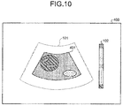
- FIG. 10 is a diagram illustrating a display example of an elastic image of the second ROI having a predetermined shape on the display device 4.
- the shape of a second ROI 401 is substantially similar to that of the first ROI 101, and the position of gravity is the same as that of the first ROI 101.
- an ultrasound miniature probe without an optical system and that has a small diameter may also be applied as an ultrasound probe.
- the ultrasound miniature probe is inserted into biliary tract, bile duct, pancreatic duct, trachea, bronchus, urethra, and urinary duct, and is used for observing the surrounding organs (pancreas, lung, prostate, urinary bladder, lymph node, and the like).
- the ultrasound probe may also be an extracorporeal ultrasound probe that emits ultrasound from the body surface of the subject.
- the extracorporeal ultrasound probe is used for observing abdominal organs (liver, gallbladder, and urinary bladder), breasts (particularly mammary gland), thyroid gland, and the like.
Landscapes
- Health & Medical Sciences (AREA)
- Life Sciences & Earth Sciences (AREA)
- Engineering & Computer Science (AREA)
- Public Health (AREA)
- Medical Informatics (AREA)
- Biomedical Technology (AREA)
- General Health & Medical Sciences (AREA)
- Pathology (AREA)
- Surgery (AREA)
- Heart & Thoracic Surgery (AREA)
- Radiology & Medical Imaging (AREA)
- Molecular Biology (AREA)
- Physics & Mathematics (AREA)
- Animal Behavior & Ethology (AREA)
- Nuclear Medicine, Radiotherapy & Molecular Imaging (AREA)
- Biophysics (AREA)
- Veterinary Medicine (AREA)
- Physiology (AREA)
- Computer Vision & Pattern Recognition (AREA)
- Vascular Medicine (AREA)
- Data Mining & Analysis (AREA)
- Databases & Information Systems (AREA)
- Epidemiology (AREA)
- Primary Health Care (AREA)
- Ultra Sonic Daignosis Equipment (AREA)
Abstract
Description
- The present invention relates to an ultrasound observation device that observes tissue of an observation target using ultrasound, an operation method of the ultrasound observation device, and an operation program of the ultrasound observation device.
- Conventionally, ultrasound elastography is known as a technique for diagnosing an observation target using ultrasound (for example, see Patent Literature 1). The ultrasound elastography is a technique that utilizes the fact that the stiffness of cancer and tumor tissue in a living body varies according to advancement of disease and the living body. In this technique, an elastic image in which information on the stiffness of biological tissue is formed into an image is generated, by adding colors on the basis of an average value of the displacement amount of the biological tissue in a predetermined region of interest (ROI).
- Patent Literature 1: Japanese Patent No.
5465671 - Generally, in the ultrasound elastography, screening of tissue such as a tumor and careful examination on the tissue are observed. To carry out these observations, a region of interest needs to be set depending on the observation content. For example, a region of interest the size (area) of which is large needs to be set to screen tissue. Alternatively, a region of interest the size (area) of which is small needs to be set to carefully examine the tissue.
- In the conventional technique described above, the user needs to change the size of the region of interest according to the observation content, and it has been troublesome to perform both observations on screening and careful examination.
- The present invention has been made in view of the above, and an object of the present invention is to provide an ultrasound observation device that can easily perform both observations on screening and careful examination in ultrasound elastography without taking trouble, an operation method of the ultrasound observation device, and the operation program of an ultrasound observation device.
- To solve the problem described above and to achieve the object, an ultrasound observation device according to the present invention is an ultrasound observation device configured to perform observation based on an ultrasound signal obtained by an ultrasound probe including an ultrasound transducer that transmits ultrasound to an observation target and receives the ultrasound reflected by the observation target. The ultrasound observation device includes: an ultrasound image generation unit configured to generate data on an ultrasound image based on the ultrasound signal; a region of interest setting unit configured to automatically set a second region of interest that is relatively stiff in a first region of interest preset within the ultrasound image; and an elastic image generation unit configured to generate data on first and second elastic images each having a display mode according to stiffness of the corresponding first and second regions of interest.
- The ultrasound observation device according to the present invention further includes a displacement amount calculation unit configured to calculate a displacement amount of the observation target in the first and second regions of interest. The region of interest setting unit is configured to set the second region of interest based on a calculation result of the displacement amount calculation unit. The elastic image generation unit is configured to generate data on the first and second elastic images each having a display mode according to the displacement amount in the corresponding first and second regions of interest.
- In the ultrasound observation device according to the present invention, the region of interest setting unit is configured to compare a displacement amount at each observation point in the first region of interest with a predetermined threshold, and set a region in which the displacement amount is smaller than the threshold as the second region of interest.
- In the ultrasound observation device according to the present invention, when the region in which the displacement in the first region of interest amount is smaller than the threshold is spatially continued for a predetermined number of times or more, and the region that is continuous is continued for a predetermined period time, the region of interest setting unit is configured to set the region as the second region of interest.
- In the ultrasound observation device according to the present invention, the region of interest setting unit is configured to: extract a contour of the observation target on the ultrasound image; and when a region in which the displacement amount at an observation point in the first region of interest is smaller than a predetermined threshold is present within a region of the extracted contour, set a closed region bounded by the contour as the second region of interest.
- The ultrasound observation device according to the present invention further includes an average image generation unit configured to generate data on an average image when an input of an average instruction signal for generating the average image obtained by adding and averaging a plurality of ultrasound images is received in a case where an input of a freeze instruction signal that causes a display on a display device to be a still image is received. The region of interest setting unit is configured to set a region in which the displacement amount at each observation point in the first region of interest in the average image is smaller than a predetermined threshold as the second region of interest.
- In the ultrasound observation device according to the present invention, when a region in which a statistical amount in the first region of interest is smaller than the threshold is spatially continued for a predetermined number of times or more, the region of interest setting unit is configured to set the region as the second region of interest.
- The ultrasound observation device according to the present invention further includes a displacement amount storage unit configured to store therein a displacement amount at each observation point in the first region of interest. The region of interest setting unit is configured to: refer to the displacement amount at each observation point in the ultrasound image stored in the displacement amount storage unit when an input of an average instruction signal for generating an average image obtained by adding and averaging a plurality of ultrasound images is received in a case where an input of a freeze instruction signal that causes a display on a display device to be a still image is received; and when matching regions the displacement amount of which is smaller than a predetermined threshold are in a predetermined number of ultrasound images or more among the ultrasound images, set the regions as the second region of interest.
- The ultrasound observation device according to the present invention further includes a display control unit configured to cause a display device to display an elastic image of a region excluding the second region of interest from the first region of interest and an elastic image of the second region of interest as a single image having an identifiable display mode.
- The ultrasound observation device according to the present invention further includes a display control unit configured to cause a display device to display an elastic image of the first region of interest and an elastic image of the second region of interest side by side.
- An operation method of an ultrasound observation device according to the present invention is an operation method of an ultrasound observation device configured to perform observation based on an ultrasound signal obtained by an ultrasound probe including an ultrasound transducer that transmits ultrasound to an observation target and receives the ultrasound reflected by the observation target. The operation method includes: a first elastic image generating step of generating, by an elastic image generation unit, data on a first elastic image having a display mode according to stiffness of a first region of interest preset within an ultrasound image that is generated based on the ultrasound signal; a region of interest setting step of setting, by a region of interest setting unit, a second region of interest that is relatively stiff in the first region of interest; and a second elastic image generating step of generating, by the elastic image generation unit, data on a second elastic image having a display mode according to stiffness of the second region of interest.
- An operation program of an ultrasound observation device according to the present invention is an operation program of an ultrasound observation device configured to perform observation based on an ultrasound signal obtained by an ultrasound probe including an ultrasound transducer that transmits ultrasound to an observation target and receives the ultrasound reflected by the observation target. The operation program causes the ultrasound observation device to execute: a first elastic image generating step of generating, by an elastic image generation unit, data on a first elastic image having a display mode according to stiffness of a first region of interest preset within an ultrasound image that is generated based on the ultrasound signal; a region of interest setting step of setting, by a region of interest setting unit, a second region of interest that is relatively stiff in the first region of interest; and a second elastic image generating step of generating, by the elastic image generation unit, data on a second elastic image having a display mode according to stiffness of the second region of interest.
- The present invention enables a user to easily perform both observations on screening and careful examination in ultrasound elastography without taking trouble.
-
-
FIG. 1 is a schematic diagram of a configuration of an ultrasound diagnostic system provided with an ultrasound observation device according to a first embodiment of the present invention. -
FIG. 2 is a flowchart illustrating the outline of processing performed by the ultrasound observation device according to the first embodiment of the present invention. -
FIG. 3 is a diagram illustrating a display example of an elastic image of a first region of interest on a display device. -
FIG. 4 is a diagram illustrating a display example of an elastic image of a second region of interest on the display device. -
FIG. 5 is a diagram illustrating a display example of an elastic image of the second ROI on the display device generated by an ultrasound observation device according to a modification 1-1 of the first embodiment of the present invention. -
FIG. 6 is a flowchart illustrating the outline of processing performed by an ultrasound observation device according to a modification 1-2 of the first embodiment of the present invention. -
FIG. 7 is a schematic diagram of a configuration of an ultrasound diagnostic system provided with an ultrasound observation device according to a second embodiment of the present invention. -
FIG. 8 is a flowchart illustrating the outline of processing performed by the ultrasound observation device according to the second embodiment of the present invention. -
FIG. 9 is a flowchart illustrating the outline of processing performed by an ultrasound observation device according to a modification 2-1 in the second embodiment of the present invention. -
FIG. 10 is a diagram illustrating a display example of an elastic image of a second region of interest on the display device in the other embodiment of the present invention. - Hereinafter, modes for carrying out the present invention (hereinafter, referred to as "embodiments") will be described in detail with reference to the accompanying drawings.
-
FIG. 1 is a schematic diagram of a configuration of an ultrasound diagnostic system provided with an ultrasound observation device according to a first embodiment of the present invention. An ultrasounddiagnostic system 1 illustrated inFIG. 1 includes anultrasound endoscope 2, an ultrasound observation device 3, and adisplay device 4. - The
ultrasound endoscope 2 includes anultrasound transducer 21 that is provided at the distal end of theultrasound endoscope 2, transmits ultrasound to the subject that is the observation target, and receives the ultrasound reflected by the subject. Theultrasound transducer 21 converts an electric pulse signal received from the ultrasound observation device 3 to an ultrasonic pulse (acoustic pulse), and emits the ultrasonic pulse to the subject. Theultrasound transducer 21 also converts an ultrasound echo reflected by the subject to an electric echo signal (ultrasound signal) to output. Theultrasound transducer 21 may be an electron scanning type or a mechanical scanning type. For example, various types of theultrasound endoscopes 2 are known depending on the observation target such as digestive canals (esophagus, stomach, duodenum, and large intestine) and respiratory organs (trachea and bronchi) of the subject. - The
ultrasound endoscope 2 may also include an imaging unit that captures an image inside the subject, and a light guide that guides illumination light from a light source device for generating illumination light emitted to the subject to the distal end of theultrasound endoscope 2 when the image is captured. - The ultrasound observation device 3 receives and transmits electric signals from and to the
ultrasound endoscope 2 via an ultrasound cable. The ultrasound observation device 3 generates an ultrasound image and the like by performing a predetermined process on an electric echo signal received from theultrasound endoscope 2. The ultrasound observation device 3 includes a transmission andreception unit 31, asignal processing unit 32, an input unit 33, a region ofinterest setting unit 34, a displacementamount calculation unit 35, animage generation unit 36, acontrol unit 37, and astorage unit 38. The transmission andreception unit 31 transmits and receives signals to and from theultrasound transducer 21. Thesignal processing unit 32 generates digital reception data on the basis of the echo signal received from the transmission andreception unit 31. The input unit 33 receives an input of various types of information including an operation instruction signal of the ultrasound observation device 3. The region ofinterest setting unit 34 sets a region of interest within an ultrasound image. The displacementamount calculation unit 35 calculates a displacement amount between images at an observation point (sampling point) within the region of interest. Theimage generation unit 36 generates data on various types of images including an ultrasound image and an elastic image. Thecontrol unit 37 integrally controls the entire operation of the ultrasounddiagnostic system 1. Thestorage unit 38 stores therein various types of information required for operating the ultrasound observation device 3. The ultrasound observation device 3 can set an elastography mode that expresses information on relative stiffness of the observation target in a region of interest by forming an image of the information using visual information such as colors. - The transmission and
reception unit 31 transmits pulse-like transmission drive wave signals to theultrasound transducer 21 on the basis of a predetermined waveform and transmission timing. The transmission andreception unit 31 also receives an electric echo signal from theultrasound transducer 21. The transmission andreception unit 31 has a function of transmitting various types of control signals output from thecontrol unit 37 to theultrasound endoscope 2, receiving various types of information including an identification ID from theultrasound endoscope 2, and transmitting the various types of information to thecontrol unit 37. - The
signal processing unit 32 performs a known process such as bandpass filtering, envelope-detection, and logarithmic conversion on an echo signal, and generates digital reception data for an ultrasound image (hereinafter, referred to as reception data). Thesignal processing unit 32 is implemented by using a general processor such as a central processing unit (CPU), a dedicated integrated circuit that executes a specific function such as an application specific integrated circuit (ASIC) or a field programmable gate array (FPGA), or the like. - The input unit 33 receives an input of a signal instructing to set a first region of interest (hereinafter, referred to as a first ROI). The input unit 33 is configured using a user interface such as a keyboard, a mouse, and a touch panel.
- The region of
interest setting unit 34 sets the first ROI on the basis of the setting input received by the input unit 33. Moreover, the region ofinterest setting unit 34 sets a region relatively stiff within the first ROI as a second region of interest (hereinafter, referred to as a second ROI), on the basis of the calculation result of the displacementamount calculation unit 35, which will be described below. - The displacement
amount calculation unit 35 calculates the displacement amount of tissue at the observation point (sampling point) within the region of interest according to the pressure applied to the subject by the heartbeat, on the basis of data on the ultrasound image generated by an ultrasoundimage generation unit 361 of theimage generation unit 36, which will be described below. For example, the displacementamount calculation unit 35 calculates the displacement amount by comparing the latest ultrasound image with the ultrasound image generated in the preceding frame. - The
image generation unit 36 includes the ultrasoundimage generation unit 361 and an elasticimage generation unit 362. The ultrasoundimage generation unit 361 generates data on the ultrasound image on the basis of reception data. The elasticimage generation unit 362 generates an elastic image that visually expresses information on the stiffness of tissue of the observation target on the basis of the displacement amount within the region of interest. - For example, the data on the ultrasound image generated by the ultrasound
image generation unit 361 is B-mode image data in which the amplitude is converted to luminance. - The elastic
image generation unit 362 generates data on first and second elastic images that each have a display mode according to the stiffness of the corresponding first and second regions of interest. The elastic image generated by the elasticimage generation unit 362 is an image obtained by applying visual information such as color and pattern on each point within the region of interest on the basis of the calculation result of the displacementamount calculation unit 35. More specifically, the elasticimage generation unit 362 generates data on an elastic image by applying green to the tissue corresponding to the average stiffness within the region of interest, bluish color to the tissue stiffer than the average, and reddish color to the tissue softer than the average. - The
control unit 37 includes adisplay control unit 371 that controls display performed by thedisplay device 4. Thedisplay control unit 371 controls thedisplay device 4 so as to display various types of images generated by theimage generation unit 36. - The
control unit 37 is implemented by using a general processor such as the CPU having calculation and control functions, or a dedicated integrated circuit such as the ASIC or the FPGA. When thecontrol unit 37 is implemented by the general processor or the FPGA, thecontrol unit 37 integrally controls the ultrasound observation device 3 by reading out various computer programs and various types of data stored in thestorage unit 38 from thestorage unit 38, and executing various arithmetic processes relating to the operation of the ultrasound observation device 3. When thecontrol unit 37 is configured using the ASIC, thecontrol unit 37 may execute various processes independently, or may execute the various processes by using the various types of data stored in thestorage unit 38. In the present first embodiment, thecontrol unit 37 and at least a part of thesignal processing unit 32, the region ofinterest setting unit 34, the displacementamount calculation unit 35, and theimage generation unit 36 may be configured using a common general processor, a dedicated integrated circuit, or the like. - The
storage unit 38 includes an ultrasoundimage storage unit 381, a region ofinterest storage unit 382, and a displacementamount storage unit 383. The ultrasoundimage storage unit 381 temporarily stores therein at least data on a plurality of the ultrasound images generated by the ultrasoundimage generation unit 361. The region ofinterest storage unit 382 stores therein information on the first ROI set for the ultrasound image. The displacementamount storage unit 383 stores therein the displacement amount calculated by the displacementamount calculation unit 35. The number of pieces of ultrasound images to be stored in the ultrasoundimage storage unit 381 is set in advance. The displacementamount storage unit 383 stores therein data on the displacement amount as much as the displacementamount calculation unit 35 requires for calculating the displacement amount. - The
storage unit 38 stores therein various computer programs including an operation program for executing the operation method of the ultrasound observation device 3. The various computer programs including the operation program may be stored in a computer readable medium such as a hard disk, a flash memory, a compact disc-read only memory (CD-ROM), a digital versatile disc-read only memory (DVD-ROM) and a flexible disk to be distributed widely. The various computer programs described above may also be obtained by downloading via a communication network. For example, the communication network described above is implemented by the existing public network, a local area network (LAN), a wide area network (WAN), and the like, and may be either wired or wireless. - The
storage unit 38 is implemented by a read only memory (ROM) in which various computer programs and the like are installed in advance, a random access memory (RAM) that stores therein operation parameter and data of various processes, and the like. - The
display device 4 is constituted of liquid crystal, organic electro luminescence (EL), or the like. Thedisplay device 4 receives image data such as an ultrasound image and an elastic image generated by the ultrasound observation device 3, and displays the images. -
FIG. 2 is a flowchart illustrating the outline of processing performed by the ultrasound observation device 3. The flowchart illustrated inFIG. 2 is a process in which the ultrasounddiagnostic system 1 is set to the elastography mode, and the setting of the first ROI in the ultrasound image is completed after the transmission andreception unit 31 starts transmitting transmission drive wave signals, and theultrasound transducer 21 starts transmitting ultrasound. - First, the transmission and
reception unit 31 receives an echo signal that is the measurement result of the observation target by theultrasound transducer 21 from the ultrasound endoscope 2 (step S1). - Next, the
signal processing unit 32 generates reception data by performing a predetermined reception process on the echo signal received from the ultrasound transducer 21 (step S2). More specifically, the transmission andreception unit 31 performs a process such as filtering and analog-to-digital (AD) conversion, after amplifying (sensitivity time control (STC) correcting) the echo signal. - The ultrasound
image generation unit 361 then generates data on the ultrasound image using the reception data generated by thesignal processing unit 32, stores the generated data in the ultrasoundimage storage unit 381, and outputs the data to thedisplay device 4 under the control of the display control unit 371 (step S3). - Subsequently, the displacement
amount calculation unit 35 calculates the displacement amount at the observation point within the first ROI stored in the region of interest storage unit 382 (step S4). In this process, the displacementamount calculation unit 35 calculates the displacement amount at each observation point, by using the latest data on the ultrasound image and the past data on the ultrasound image stored in the ultrasoundimage storage unit 381. - The elastic
image generation unit 362 then generates data on the elastic image of the first ROI (first elastic image) using the calculation result of the displacement amount at each observation point at step S4, and outputs the data to the display device 4 (step S5).FIG. 3 is a diagram illustrating a display example of an elastic image of the first ROI on thedisplay device 4. Anelastic image 100 illustrated inFIG. 3 is displayed as an image in which the stiffness of each tissue inside afirst ROI 101 is identifiable by color. InFIG. 3 , the differences in colors are schematically expressed by patterns. Acolor scale 102 indicating the colors to be used in theelastic image 100 is displayed at the right side of thefirst ROI 101. For example, the tissue becomes stiffer in descending order from top to bottom in thecolor scale 102. InFIG. 3 , only a part of thecolor scale 102 is schematically illustrated. The displacement amount of aregion 111 inFIG. 3 is average. Alternatively, aregion 121 is a softest region, and aregion 131 is a stiffest region. Thedisplay device 4 displays a B mode image and theelastic image 100 side by side. Thedisplay device 4 may also display theelastic image 100 on the B mode image in an overlapping manner. In this case, theimage generation unit 36 generates data on an image in which theelastic image 100 is overlapped with the B mode image, and outputs the data on the image to thedisplay device 4 under the control of thedisplay control unit 371. - Subsequently, the region of
interest setting unit 34 extracts a region in which the displacement amount is equal to or less than a threshold within the first ROI (step S6). For example, the threshold in this case is set as a value the displacement amount of which is smaller than a reference value as much as a predetermined amount, on the basis of the average of the displacement amount within the first ROI. Moreover, the threshold may be the average value of the displacement amount within the first ROI. The reference value may also be a statistical amount such as the center value or the most frequent value of the displacement amount within the first ROI. - Then, the region of
interest setting unit 34 determines whether the minimum unit region (pixel or block) is continued for a predetermined number of times or more in the extracted region (step S7). In this example, for example, the predetermined number of times is the number corresponding to the size that a user can view the continuous region on the screen. As a result of determination, when the minimum unit region is continued for a predetermined number of times or more (Yes at step S7), the region ofinterest setting unit 34 determines whether the continuous region is continuously equal to or less than the threshold for a predetermined time, by referring to a plurality of the past displacement amounts stored in the displacement amount storage unit 383 (step S8). As a result of determination, when the continuous region is continuously equal to or less than the threshold for a predetermined time (Yes at step S8), the region ofinterest setting unit 34 sets the region as the second ROI (step S9). In this example, for example, the predetermined time is about the same time as the heartbeat cycle of the subject. - After step S9, the elastic
image generation unit 362 generates data on an elastic image of the second ROI (second elastic image), and outputs the data to thedisplay device 4 under the control of the display control unit 371 (step S10).FIG. 4 is a diagram illustrating a display example of an elastic image of the second ROI on thedisplay device 4. Anelastic image 200 illustrated inFIG. 4 is displayed as an image in which the stiffness of each tissue inside asecond ROI 201 is identifiable by color. Similar toFIG. 3 , inFIG. 4 also, the differences in colors are schematically expressed by patterns. The displacement amount of aregion 211 in theelastic image 200 is average. Alternatively, aregion 221 is a relatively soft region, and aregion 231 is a stiffest region. The display device displays theelastic image 200 and theelastic image 100 side by side. Similar to theelastic image 100, thedisplay device 4 may also display theelastic image 200 on the B mode image in an overlapping manner. In this case, theimage generation unit 36 generates data on an image in which theelastic image 200 is overlapped with the B mode image, and outputs the data on the image to thedisplay device 4 under the control of thedisplay control unit 371. After step S10, the ultrasound observation device 3 finishes the series of processes. - When the minimum unit region is not continued for a predetermined number of times or more at step S7 (No at step S7), or when the continuous region is not continuously equal to or less than the threshold for a predetermined time at step S8 (No at step S8), the ultrasound observation device 3 finishes the series of processes.
- While being set to the elastography mode, the ultrasound observation device 3 performs the processes from step S1 to step S10 every time an echo signal is received.
- The first embodiment of the present invention as described above can eliminate the need of setting the second ROI, because the second ROI that is relatively stiff within the first ROI is automatically set while the elastic image of the first ROI is displayed in real time, and the elastic image of the second ROI is generated. Consequently, it is possible to easily perform both observations on screening and careful examination in the ultrasound elastography without taking trouble.
- With the present first embodiment, when a region in which the displacement amount is smaller than the threshold within the first ROI is spatially continued, and the continuous region is continued for a predetermined time, the region is set as the second ROI. Consequently, it is possible to accurately set a region in which the displacement amount does not change continuously over a plurality of frames (region where the displacement amount is not changed over time) as the second ROI, even when the ultrasound elastography is performed by using the heartbeat of a living body that is the observation target, as the ultrasound endoscope.
-
FIG. 5 is a diagram illustrating a display example of an elastic image of the second ROI on thedisplay device 4 generated by an ultrasound observation device according to a modification 1-1 of the present first embodiment. In anelastic image 300 illustrated inFIG. 5 , a region excluding a second ROI 201' from thefirst ROI 101 and the second ROI 201' corresponding to the excluded region are displayed in a single image in different color scales. Consequently, in theelastic image 300, acolor scale 301 of the elastic image of the second ROI 201' in addition to thecolor scale 102 of the elastic image of thefirst ROI 101 are displayed side by side. For comparison convenience, theelastic image 300 inFIG. 5 is assumed to observe the same tissue as that of the correspondingelastic images FIG. 3 and FIG. 4 . Consequently, regions 211', 221', 231' respectively correspond to theregions FIG. 4 . - In the
elastic image 300, the same color as that of theregion 121 inFIG. 3 is applied to a boundary portion B between the second ROI 201' and thefirst ROI 101 on the basis of thecolor scale 102 of thefirst ROI 101. In this manner, by displaying thefirst ROI 101 and the second ROI 201' in an identifiable display mode, the user can easily identify the boundary between thefirst ROI 101 and the second ROI 201'. In the present modification 1-1, at least the color scales of thefirst ROI 101 and the second ROI 201' may be different, and the boundary portion B may not be displayed. -
FIG. 6 is a flowchart illustrating the outline of processing performed by an ultrasound observation device according to a modification 1-2 of the present first embodiment. The flowchart illustrated inFIG. 6 is also a process in which the ultrasounddiagnostic system 1 is set to the elastography mode, and the setting of the first ROI in the ultrasound image is completed, after the transmission andreception unit 31 starts transmitting transmission drive wave signals, and theultrasound transducer 21 starts transmitting ultrasound. Processes from step S21 to step S26 sequentially correspond to the processes from step S1 to step S6 described in the first embodiment. - At step S27, the region of
interest setting unit 34 performs a contour extraction (edge extraction) process on the B mode image (step S27). For example, the region ofinterest setting unit 34 extracts contour by applying a known filter such as Sobel or Laplacian. - When a region in which the displacement amount is equal to or less than a threshold is present within the region of the contour that is extracted (Yes at step S28), the region of
interest setting unit 34 sets a closed region bounded by the outline as the second ROI (step S29). In this example also, based on the average value of the displacement amount within the first ROI, the threshold is set as a value the displacement amount of which is smaller than the reference value as much as a predetermined amount. - Then, the elastic
image generation unit 362 generates data on the elastic image of the second ROI, and outputs the data to the display device 4 (step S30). - At step S28, when a region in which the displacement amount is equal to or less than a threshold is not present within the region of the contour that is extracted (No at step S28), the ultrasound observation device 3 finishes the series of processes.
- With the present modification 1-2 described above, it is possible to accurately set the relatively stiff region as the second ROI, because the contour of the observation target on the ultrasound image is extracted, and the closed region bounded by the extracted contour is set as the second region of interest, among the regions in which the displacement amount at each observation point within the first region of interest is smaller than a predetermined threshold.
-
FIG. 7 is a schematic diagram of a configuration of an ultrasound diagnostic system provided with an ultrasound observation device according to a second embodiment of the present invention. An ultrasounddiagnostic system 5 illustrated inFIG. 7 includes theultrasound endoscope 2, anultrasound observation device 6, and thedisplay device 4. The configuration of the ultrasounddiagnostic system 5 other than theultrasound observation device 6 is the same as that of the ultrasounddiagnostic system 1 described in the first embodiment. - The configuration of an image generation unit in the
ultrasound observation device 6 is different from that in the ultrasound observation device 3 described in the first embodiment. Animage generation unit 61 provided in theultrasound observation device 6 includes an average image generation unit 611 in addition to the ultrasoundimage generation unit 361 and the elasticimage generation unit 362. - When a freeze instruction signal that makes the display on the
display device 4 into a still image is input from the input unit 33, and when an average instruction signal is further input from the input unit 33, the average image generation unit 611 generates data on the average image by adding and averaging pixel values of pixels of a plurality of the ultrasound images that are formed of the ultrasound images specified by the average instruction signal. The input unit 33 receives an input of selecting the images to be added and averaged. More specifically, when the input unit 33 receives an input of an average instruction signal, thedisplay control unit 371 causes thedisplay device 4 to display the past ultrasound image to be added and averaged. In this process, thedisplay control unit 371 may cause thedisplay device 4 to display a single ultrasound image at a time, or may cause thedisplay device 4 to display several pieces of ultrasound images at a time. The average image generation unit 611 generates data on the average image using the ultrasound images selected from the ultrasound images displayed on thedisplay device 4. - The region of
interest setting unit 34 sets the second ROI relative to the average image, on the basis of the data on the average image generated by the average image generation unit 611. The elasticimage generation unit 362 automatically generates data on the elastic image of the second ROI in the average image. -
FIG. 8 is a flowchart illustrating the outline of processing performed by theultrasound observation device 6. The flowchart illustrated inFIG. 8 is also a process in which the ultrasounddiagnostic system 5 is set to the elastography mode, and the setting of the first ROI in the ultrasound image is completed after the transmission andreception unit 31 starts transmitting transmission drive wave signals, and theultrasound transducer 21 starts transmitting ultrasound. Processes from step S41 to step S45 sequentially correspond to the processes from step S1 to step S5 described in the first embodiment. - After step S45, when the input unit 33 receives an input of a freeze instruction signal (Yes at step S46), the process proceeds to step S47. Alternatively, after step S45, when the input unit 33 does not receive the freeze instruction signal (No at step S46), the
ultrasound observation device 6 finishes the series of processes. - At step S47, when the input unit 33 receives an input of the average instruction signal (Yes at step S47), the
image generation unit 36 generates data on the average image by adding and averaging the pixel values of the pixels of the ultrasound images that are formed of the ultrasound images specified by the average instruction signal (step S48). - The displacement
amount calculation unit 35 then calculates the displacement amount at each observation point within the first ROI in the average image (step S49). The displacementamount calculation unit 35 reads out the displacement amount at each observation point in the ultrasound images that form the average image from the displacementamount storage unit 383, and calculates the average of the displacement amount at each observation point. The average will be the displacement amount at each observation point of the average image. - Subsequently, the region of
interest setting unit 34 extracts a region in which the displacement amount is equal to or less than a threshold within the first ROI in the average image (step S50). This threshold is set as a value the displacement amount of which is smaller than a reference value as much as the predetermined amount, assuming that the average obtained when the displacement amount at each observation point within the first ROI in the average image is population is the reference value. The reference value may also be the threshold. The statistical amount such as the center value or the most frequent value may be applied as the reference value, instead of the average. - The region of
interest setting unit 34 then determines whether the minimum unit region (pixel or block) in the extracted region is continued for a predetermined number of times or more (step S51). The predetermined number is the same as the number described at step S7 in the first embodiment. When determination reveals that the minimum unit region in the extracted region is continued for a predetermined number of times or more (Yes at step S51), the region ofinterest setting unit 34 sets the region as the second ROI (step S52). On the other hand, when the minimum unit region in the extracted region is not continued for a predetermined number of times or more (No at step S51), theultrasound observation device 6 finishes the series of processes. - After step S52, the elastic
image generation unit 362 generates data on an elastic image of the second ROI (second elastic image) set in the average image, and outputs the data to thedisplay device 4 under the control of the display control unit 371 (step S53). After step S53, theultrasound observation device 6 finishes the series of processes. Thedisplay device 4 displays the average image and the elastic image of the second ROI side by side. Thedisplay device 4 may also display the average image and the elastic image of the second ROI in an overlapping manner. - The following describes a case when the input unit 33 does not receive the average instruction signal at step S47 (No at step S47). In this case, the region of
interest setting unit 34 extracts a region in which the displacement amount is equal to or less than a threshold within the first ROI (step S54). The threshold in this process is the same as the threshold at step S6 described in the first embodiment. Theultrasound observation device 6 then proceeds the process to step S51. - The elastic
image generation unit 362 may also generate data on the elastic image of the first ROI in the average image and output the data to thedisplay device 4. In this case, thedisplay device 4 displays the average image and the elastic images of the first and second ROI. - The second embodiment of the present invention described above can eliminates the need of setting the second ROI, because the freeze operation is performed while the elastic image of the first ROI is displayed, the data on the average image of a predetermined number of ultrasound images is generated when the average instruction operation is performed, the relatively stiff second ROI is automatically set within the first ROI in the average image, and the elastic image relative to the second ROI is generated. Consequently, it is possible to easily perform both observations on screening and careful examination in the ultrasound elastography without taking trouble.
- Moreover, with the present second embodiment, when a region in which the displacement amount is smaller than the threshold within the first ROI is spatially continued, the region is set as the second ROI. Consequently, it is possible to accurately set the second ROI as the region in which the displacement amount does not change continuously over a plurality of frames, even when the ultrasound elastography is performed by using the heartbeat of a living body that is the observation target, as the ultrasound endoscope.
-
FIG. 9 is a flowchart illustrating the outline of processing performed by an ultrasound observation device according to a modification 2-1 in the present second embodiment. The flowchart illustrated inFIG. 9 is also a process in which the ultrasounddiagnostic system 5 is set to the elastography mode, and the setting of the first ROI in the ultrasound image is completed after the transmission andreception unit 31 starts transmitting transmission drive wave signals, and theultrasound transducer 21 starts transmitting ultrasound. Processes from step S61 to step S67 sequentially correspond to the processes from step S41 to step S47 described in the second embodiment. - At step S67, when the input unit 33 receives an input of an average instruction signal (Yes at step S67), the region of
interest setting unit 34 refers to the displacementamount storage unit 383, and extracts the region in which the displacement amount is equal to or less than a threshold within the first ROI in the selected ultrasound image (step S68). This threshold is set similarly to that in the second embodiment. - Subsequently, the region of
interest setting unit 34 determines whether there are matching regions equal to or less than a threshold in a predetermined number of ultrasound images or more (step S69). When determination reveals that matching regions equal to or less than the threshold are in the predetermined number of ultrasound images or more (Yes at step S69), the region ofinterest setting unit 34 sets the corresponding regions as the second ROI (step S70). Alternatively, when matching regions equal to or less than the threshold are not in the predetermined number of ultrasound images or more (No at step S69), theultrasound observation device 6 finishes the series of processes. - After step S70, the average image generation unit 611 generates data on the average image and the elastic
image generation unit 362 generates data on the elastic image of the second ROI to output (step S71). The generated data on the average image and the elastic image of the second ROI are output to thedisplay device 4 under the control of thedisplay control unit 371. Theultrasound observation device 6 then finishes the series of processes. The process of the average image generation unit 611 may also be performed in parallel with the processes from step S68 to step S70 described above. - The following describes a case when the input unit 33 does not receive the average instruction signal (No at step S67) at step S67. In this case, the region of
interest setting unit 34 extracts a region in which the displacement amount is equal to or less than a threshold within the first ROI (step S72). This threshold is also the same as the threshold at step S6 described in the first embodiment. - Processes from step S73 to step S75 performed after step S72 respectively correspond to the processes from step S51 to step S53 described in the second embodiment. After step S75, the
ultrasound observation device 6 finishes the series of processes. - The present modification 2-1 described above can accurately set the relatively stiff region as the second ROI, because the displacement amount at each observation point of each of the ultrasound images stored in the displacement amount storage unit is referred to, and when matching regions the displacement amount of which is smaller than the threshold are in the predetermined number of ultrasound images or more in the ultrasound images, the regions are set as the second ROI.
- The modes for carrying out the present invention have been described. However, the present invention is not only limited to the first and second embodiments described above. For example, the second ROI may be set by a predetermined shape.
FIG. 10 is a diagram illustrating a display example of an elastic image of the second ROI having a predetermined shape on thedisplay device 4. In anelastic image 400 illustrated inFIG. 10 , the shape of asecond ROI 401 is substantially similar to that of thefirst ROI 101, and the position of gravity is the same as that of thefirst ROI 101. - For example, an ultrasound miniature probe without an optical system and that has a small diameter may also be applied as an ultrasound probe. In general, the ultrasound miniature probe is inserted into biliary tract, bile duct, pancreatic duct, trachea, bronchus, urethra, and urinary duct, and is used for observing the surrounding organs (pancreas, lung, prostate, urinary bladder, lymph node, and the like). The ultrasound probe may also be an extracorporeal ultrasound probe that emits ultrasound from the body surface of the subject. In general, the extracorporeal ultrasound probe is used for observing abdominal organs (liver, gallbladder, and urinary bladder), breasts (particularly mammary gland), thyroid gland, and the like.
- In this manner, the present invention may include various embodiments within the scope of the technical idea disclosed in the appended claims.
-
- 1, 5 ultrasound diagnostic system
- 2 ultrasound endoscope
- 3, 6 ultrasound observation device
- 4 display device
- 21 ultrasound transducer
- 31 transmission and reception unit
- 32 signal processing unit
- 33 input unit
- 34 region of interest setting unit
- 35 displacement amount calculation unit
- 36, 61 image generation unit
- 37 control unit
- 38 storage unit
- 100, 200, 300, 400 elastic image
- 101 first ROI
- 102, 301 color scale
- 201, 201', 401 second ROI
- 361 ultrasound image generation unit
- 362 elastic image generation unit
- 371 display control unit
- 381 ultrasound image storage unit
- 382 region of interest storage unit
- 383 displacement amount storage unit
- 611 average image generation unit
- B boundary portion
Claims (12)
- An ultrasound observation device configured to perform observation based on an ultrasound signal obtained by an ultrasound probe including an ultrasound transducer that transmits ultrasound to an observation target and receives the ultrasound reflected by the observation target, the ultrasound observation device comprising:an ultrasound image generation unit configured to generate data on an ultrasound image based on the ultrasound signal;a region of interest setting unit configured to automatically set a second region of interest that is relatively stiff in a first region of interest preset within the ultrasound image; andan elastic image generation unit configured to generate data on first and second elastic images each having a display mode according to stiffness of the corresponding first and second regions of interest.
- The ultrasound observation device according to claim 1, further comprising a displacement amount calculation unit configured to calculate a displacement amount of the observation target in the first and second regions of interest, whereinthe region of interest setting unit is configured to set the second region of interest based on a calculation result of the displacement amount calculation unit, andthe elastic image generation unit is configured to generate data on the first and second elastic images each having a display mode according to the displacement amount in the corresponding first and second regions of interest.
- The ultrasound observation device according to claim 2, wherein the region of interest setting unit is configured to compare a displacement amount at each observation point in the first region of interest with a predetermined threshold, and set a region in which the displacement amount is smaller than the threshold as the second region of interest.
- The ultrasound observation device according to claim 3, wherein when the region in which the displacement in the first region of interest amount is smaller than the threshold is spatially continued for a predetermined number of times or more, and the region that is continuous is continued for a predetermined period time, the region of interest setting unit is configured to set the region as the second region of interest.
- The ultrasound observation device according to claim 2, whereinthe region of interest setting unit is configured to:extract a contour of the observation target on the ultrasound image; andwhen a region in which the displacement amount at an observation point in the first region of interest is smaller than a predetermined threshold is present within a region of the extracted contour, set a closed region bounded by the contour as the second region of interest.
- The ultrasound observation device according to claim 2, further comprising an average image generation unit configured to generate data on an average image when an input of an average instruction signal for generating the average image obtained by adding and averaging a plurality of ultrasound images is received in a case where an input of a freeze instruction signal that causes a display on a display device to be a still image is received, whereinthe region of interest setting unit is configured to set a region in which the displacement amount at each observation point in the first region of interest in the average image is smaller than a predetermined threshold as the second region of interest.
- The ultrasound observation device according to claim 6, wherein when a region in which a statistical amount in the first region of interest is smaller than the threshold is spatially continued for a predetermined number of times or more, the region of interest setting unit is configured to set the region as the second region of interest.
- The ultrasound observation device according to claim 2, further comprising a displacement amount storage unit configured to store therein a displacement amount at each observation point in the first region of interest, whereinthe region of interest setting unit is configured to:refer to the displacement amount at each observation point in the ultrasound image stored in the displacement amount storage unit when an input of an average instruction signal for generating an average image obtained by adding and averaging a plurality of ultrasound images is received in a case where an input of a freeze instruction signal that causes a display on a display device to be a still image is received; andwhen matching regions the displacement amount of which is smaller than a predetermined threshold are in a predetermined number of ultrasound images or more among the ultrasound images, set the regions as the second region of interest.
- The ultrasound observation device according to claim 1, further comprising a display control unit configured to cause a display device to display an elastic image of a region excluding the second region of interest from the first region of interest and an elastic image of the second region of interest as a single image having an identifiable display mode.
- The ultrasound observation device according to claim 1, further comprising a display control unit configured to cause a display device to display an elastic image of the first region of interest and an elastic image of the second region of interest side by side.
- An operation method of an ultrasound observation device configured to perform observation based on an ultrasound signal obtained by an ultrasound probe including an ultrasound transducer that transmits ultrasound to an observation target and receives the ultrasound reflected by the observation target, the operation method comprising:a first elastic image generating step of generating, by an elastic image generation unit, data on a first elastic image having a display mode according to stiffness of a first region of interest preset within an ultrasound image that is generated based on the ultrasound signal;a region of interest setting step of setting, by a region of interest setting unit, a second region of interest that is relatively stiff in the first region of interest; anda second elastic image generating step of generating, by the elastic image generation unit, data on a second elastic image having a display mode according to stiffness of the second region of interest.
- An operation program of an ultrasound observation device configured to perform observation based on an ultrasound signal obtained by an ultrasound probe including an ultrasound transducer that transmits ultrasound to an observation target and receives the ultrasound reflected by the observation target, the operation program causing the ultrasound observation device to execute:a first elastic image generating step of generating, by an elastic image generation unit, data on a first elastic image having a display mode according to stiffness of a first region of interest preset within an ultrasound image that is generated based on the ultrasound signal;a region of interest setting step of setting, by a region of interest setting unit, a second region of interest that is relatively stiff in the first region of interest; anda second elastic image generating step of generating, by the elastic image generation unit, data on a second elastic image having a display mode according to stiffness of the second region of interest.
Applications Claiming Priority (2)
| Application Number | Priority Date | Filing Date | Title |
|---|---|---|---|
| JP2015247567 | 2015-12-18 | ||
| PCT/JP2016/086950 WO2017104627A1 (en) | 2015-12-18 | 2016-12-12 | Ultrasonic observation device, operation method for ultrasonic observation device, and operation program for ultrasonic observation device |
Publications (2)
| Publication Number | Publication Date |
|---|---|
| EP3391826A1 true EP3391826A1 (en) | 2018-10-24 |
| EP3391826A4 EP3391826A4 (en) | 2019-07-31 |
Family
ID=59056680
Family Applications (1)
| Application Number | Title | Priority Date | Filing Date |
|---|---|---|---|
| EP16875604.7A Withdrawn EP3391826A4 (en) | 2015-12-18 | 2016-12-12 | Ultrasonic observation device, operation method for ultrasonic observation device, and operation program for ultrasonic observation device |
Country Status (5)
| Country | Link |
|---|---|
| US (1) | US11071523B2 (en) |
| EP (1) | EP3391826A4 (en) |
| JP (1) | JP6513220B2 (en) |
| CN (1) | CN108366781A (en) |
| WO (1) | WO2017104627A1 (en) |
Families Citing this family (6)
| Publication number | Priority date | Publication date | Assignee | Title |
|---|---|---|---|---|
| CN107404615B (en) * | 2017-06-29 | 2020-08-25 | 联想(北京)有限公司 | Image recording method and electronic equipment |
| WO2019220916A1 (en) * | 2018-05-14 | 2019-11-21 | 富士フイルム株式会社 | Medical image processing device, medical image processing method, and endoscope system |
| EP3845132B1 (en) * | 2018-08-29 | 2026-04-15 | FUJIFILM Corporation | Ultrasonic diagnostic device and ultrasonic diagnostic device control method |
| EP3865074B1 (en) * | 2018-10-12 | 2024-10-23 | FUJIFILM Corporation | Ultrasonic diagnostic device and control method for ultrasonic diagnostic device |
| CN114926389B (en) * | 2022-03-30 | 2024-07-09 | 什维新智医疗科技(上海)有限公司 | Elastic signal extraction device for ultrasonic image |
| WO2025129187A1 (en) * | 2023-12-15 | 2025-06-19 | University Of Southern California | System and method for extended and/or continuous ultrasound elastography |
Family Cites Families (15)
| Publication number | Priority date | Publication date | Assignee | Title |
|---|---|---|---|---|
| US5615680A (en) * | 1994-07-22 | 1997-04-01 | Kabushiki Kaisha Toshiba | Method of imaging in ultrasound diagnosis and diagnostic ultrasound system |
| US7050610B2 (en) * | 2001-04-04 | 2006-05-23 | Siemens Medical Solutions Usa, Inc. | Method and system for improving the spatial resolution for strain imaging |
| JP4233808B2 (en) * | 2002-06-04 | 2009-03-04 | 株式会社日立メディコ | Ultrasonic diagnostic equipment |
| JP5203605B2 (en) * | 2004-06-18 | 2013-06-05 | 株式会社日立メディコ | Ultrasonic diagnostic equipment |
| JP3991282B2 (en) * | 2004-08-05 | 2007-10-17 | 株式会社日立メディコ | Elastic image display method and ultrasonic diagnostic apparatus |
| EP1815796A4 (en) * | 2004-11-17 | 2009-10-28 | Hitachi Medical Corp | ULTRASONIC UNIT AND METHOD FOR DISPLAYING AN ULTRASOUND IMAGE |
| JP2009261493A (en) * | 2008-04-23 | 2009-11-12 | Konica Minolta Medical & Graphic Inc | Ultrasonic diagnostic method and apparatus |
| JP5465671B2 (en) | 2008-08-29 | 2014-04-09 | 株式会社日立メディコ | Ultrasonic diagnostic equipment |
| JP5269528B2 (en) * | 2008-09-09 | 2013-08-21 | オリンパスメディカルシステムズ株式会社 | Ultrasonic image display device |
| US20110255762A1 (en) * | 2010-04-15 | 2011-10-20 | Harald Deischinger | Method and system for determining a region of interest in ultrasound data |
| CN104470443B (en) * | 2012-07-18 | 2017-10-31 | 皇家飞利浦有限公司 | Method and system for handling ultrasound imaging data |
| US11020094B2 (en) | 2012-07-18 | 2021-06-01 | Koninklijke Philips N.V. | Method and system for processing ultrasonic imaging data |
| WO2016031273A1 (en) * | 2014-08-25 | 2016-03-03 | オリンパス株式会社 | Ultrasound observation apparatus, ultrasound observation system, and method for operating ultrasound observation apparatus |
| JP6216736B2 (en) * | 2015-04-08 | 2017-10-18 | 株式会社日立製作所 | Ultrasonic diagnostic apparatus and ultrasonic diagnostic method |
| US10813624B2 (en) * | 2015-10-30 | 2020-10-27 | Carestream Health, Inc. | Ultrasound display method |
-
2016
- 2016-12-12 CN CN201680073933.0A patent/CN108366781A/en active Pending
- 2016-12-12 WO PCT/JP2016/086950 patent/WO2017104627A1/en not_active Ceased
- 2016-12-12 JP JP2017556051A patent/JP6513220B2/en active Active
- 2016-12-12 EP EP16875604.7A patent/EP3391826A4/en not_active Withdrawn
-
2018
- 2018-06-15 US US16/009,719 patent/US11071523B2/en active Active
Also Published As
| Publication number | Publication date |
|---|---|
| JP6513220B2 (en) | 2019-05-15 |
| JPWO2017104627A1 (en) | 2018-10-04 |
| US11071523B2 (en) | 2021-07-27 |
| CN108366781A (en) | 2018-08-03 |
| WO2017104627A1 (en) | 2017-06-22 |
| EP3391826A4 (en) | 2019-07-31 |
| US20180289358A1 (en) | 2018-10-11 |
Similar Documents
| Publication | Publication Date | Title |
|---|---|---|
| US11071523B2 (en) | Ultrasound observation device, operation method of ultrasound observation device, and computer-readable recording medium | |
| JP5276225B2 (en) | Medical image processing apparatus and method of operating medical image processing apparatus | |
| US20060079781A1 (en) | Ultrasonic apparatus for estimating artery parameters | |
| EP2047791B1 (en) | Medical image processing apparatus and medical image processing method | |
| EP1994878A1 (en) | Image processing device for medical use and image processing method for medical use | |
| KR20050084366A (en) | Ultrasonic doppler system for determining movement of artery walls | |
| JP6651810B2 (en) | Ultrasound image diagnostic equipment | |
| JPWO2012153568A1 (en) | Medical image processing device | |
| JP5078486B2 (en) | Medical image processing apparatus and method of operating medical image processing apparatus | |
| KR20160118037A (en) | Apparatus and method for detecting lesion from medical image automatically | |
| EP3354203A1 (en) | Ultrasonic observation device | |
| US20190008483A1 (en) | Ultrasound observation apparatus, method of operating ultrasound observation apparatus, and computer readable recording medium | |
| CN113842162A (en) | Ultrasonic diagnostic apparatus and diagnostic support method | |
| EP3238636A1 (en) | Medical diagnostic device, ultrasonic observation system, method for operating medical diagnostic device, and program for operating medical diagnostic device | |
| US20190142385A1 (en) | Ultrasonic observation apparatus, method of operating ultrasonic observation apparatus, and program for operating ultrasonic observation apparatus | |
| JP7161544B2 (en) | Ultrasonic Observation System, Method of Operating Ultrasonic Observation System, and Operation Program for Ultrasonic Observation System | |
| JP6530660B2 (en) | Ultrasonic observation apparatus, operation method of ultrasonic observation apparatus, and operation program of ultrasonic observation apparatus | |
| CN113556979B (en) | Ultrasonic observation device, working method of ultrasonic observation device, and working procedure of ultrasonic observation device | |
| US12002201B2 (en) | Ultrasonic diagnostic device, operation method of ultrasonic diagnostic device, and computer readable recording medium | |
| JP2017217359A (en) | Ultrasound observation apparatus, operation method for ultrasound observation apparatus, and operation program for ultrasound observation apparatus | |
| JP6707014B2 (en) | Ultrasonic observation device, ultrasonic observation system, operating method of ultrasonic observation device, and operating program of ultrasonic observation device | |
| EP4338683A1 (en) | Image processing device, image processing system, image processing method, and image processing program |
Legal Events
| Date | Code | Title | Description |
|---|---|---|---|
| STAA | Information on the status of an ep patent application or granted ep patent |
Free format text: STATUS: THE INTERNATIONAL PUBLICATION HAS BEEN MADE |
|
| PUAI | Public reference made under article 153(3) epc to a published international application that has entered the european phase |
Free format text: ORIGINAL CODE: 0009012 |
|
| STAA | Information on the status of an ep patent application or granted ep patent |
Free format text: STATUS: REQUEST FOR EXAMINATION WAS MADE |
|
| 17P | Request for examination filed |
Effective date: 20180713 |
|
| AK | Designated contracting states |
Kind code of ref document: A1 Designated state(s): AL AT BE BG CH CY CZ DE DK EE ES FI FR GB GR HR HU IE IS IT LI LT LU LV MC MK MT NL NO PL PT RO RS SE SI SK SM TR |
|
| AX | Request for extension of the european patent |
Extension state: BA ME |
|
| DAV | Request for validation of the european patent (deleted) | ||
| DAX | Request for extension of the european patent (deleted) | ||
| A4 | Supplementary search report drawn up and despatched |
Effective date: 20190701 |
|
| RIC1 | Information provided on ipc code assigned before grant |
Ipc: A61B 8/00 20060101ALI20190625BHEP Ipc: A61B 8/12 20060101ALI20190625BHEP Ipc: A61B 8/08 20060101AFI20190625BHEP |
|
| STAA | Information on the status of an ep patent application or granted ep patent |
Free format text: STATUS: THE APPLICATION IS DEEMED TO BE WITHDRAWN |
|
| 18D | Application deemed to be withdrawn |
Effective date: 20200129 |