EP3390882B1 - Improved modular heater systems - Google Patents
Improved modular heater systems Download PDFInfo
- Publication number
- EP3390882B1 EP3390882B1 EP16823119.9A EP16823119A EP3390882B1 EP 3390882 B1 EP3390882 B1 EP 3390882B1 EP 16823119 A EP16823119 A EP 16823119A EP 3390882 B1 EP3390882 B1 EP 3390882B1
- Authority
- EP
- European Patent Office
- Prior art keywords
- carrier member
- thermal insulation
- modular
- insulation jacket
- modular heater
- Prior art date
- Legal status (The legal status is an assumption and is not a legal conclusion. Google has not performed a legal analysis and makes no representation as to the accuracy of the status listed.)
- Active
Links
Images








Classifications
-
- F—MECHANICAL ENGINEERING; LIGHTING; HEATING; WEAPONS; BLASTING
- F16—ENGINEERING ELEMENTS AND UNITS; GENERAL MEASURES FOR PRODUCING AND MAINTAINING EFFECTIVE FUNCTIONING OF MACHINES OR INSTALLATIONS; THERMAL INSULATION IN GENERAL
- F16L—PIPES; JOINTS OR FITTINGS FOR PIPES; SUPPORTS FOR PIPES, CABLES OR PROTECTIVE TUBING; MEANS FOR THERMAL INSULATION IN GENERAL
- F16L53/00—Heating of pipes or pipe systems; Cooling of pipes or pipe systems
- F16L53/30—Heating of pipes or pipe systems
- F16L53/35—Ohmic-resistance heating
- F16L53/38—Ohmic-resistance heating using elongate electric heating elements, e.g. wires or ribbons
-
- H—ELECTRICITY
- H05—ELECTRIC TECHNIQUES NOT OTHERWISE PROVIDED FOR
- H05B—ELECTRIC HEATING; ELECTRIC LIGHT SOURCES NOT OTHERWISE PROVIDED FOR; CIRCUIT ARRANGEMENTS FOR ELECTRIC LIGHT SOURCES, IN GENERAL
- H05B3/00—Ohmic-resistance heating
- H05B3/02—Details
- H05B3/06—Heater elements structurally combined with coupling elements or holders
-
- H—ELECTRICITY
- H05—ELECTRIC TECHNIQUES NOT OTHERWISE PROVIDED FOR
- H05B—ELECTRIC HEATING; ELECTRIC LIGHT SOURCES NOT OTHERWISE PROVIDED FOR; CIRCUIT ARRANGEMENTS FOR ELECTRIC LIGHT SOURCES, IN GENERAL
- H05B3/00—Ohmic-resistance heating
- H05B3/10—Heating elements characterised by the composition or nature of the materials or by the arrangement of the conductor
-
- H—ELECTRICITY
- H05—ELECTRIC TECHNIQUES NOT OTHERWISE PROVIDED FOR
- H05B—ELECTRIC HEATING; ELECTRIC LIGHT SOURCES NOT OTHERWISE PROVIDED FOR; CIRCUIT ARRANGEMENTS FOR ELECTRIC LIGHT SOURCES, IN GENERAL
- H05B2203/00—Aspects relating to Ohmic resistive heating covered by group H05B3/00
- H05B2203/021—Heaters specially adapted for heating liquids
Definitions
- the present disclosure relates generally to electric heaters for use in pipelines, and more particularly to electric heaters for use in gaslines and pumplines such as, by way of example, semiconductor processing systems.
- an electric heater in the form of a cable or a tape known in the art as a "heat trace” is commonly used around the conduits to provide heat to the conduits and thus to the fluids.
- the conduits and the heat traces are sometimes surrounded by a thermal insulation jacket to reduce heat loss to the surrounding environment.
- Such conduits and heat traces surrounded by a thermal insulation jacket have been disclosed in US 2009/016707 , WO 2007/019564 and US 4,429,213 .
- Heat trace cables are a popular means for heating such fluid conduits due to their relative simplicity and low cost.
- heat trace cables are disposed along the length of the conduits or wrapped around the conduits and are fastened at regular intervals with bands, retaining straps or any other suitable fasteners, as shown in U.S. Patent No. 5,294,780 to Montierth et al. , U.S. Patent No. 5,086,836 to Barth et al. , U.S. Patent No. 4,791,277 to Montierth et al. , U.S. Patent No. 4,152,577 to Leavines , U.S. Patent No. 4,123,837 to Horner , U.S. Patent No.
- U.S. Patent No. 6,792,200 proposes a pre-fabricated heat-traced pipe, wherein a pipe to be heated, a heat trace, and a connector for electrically connecting the heat trace to a power source are cured and integrally formed beforehand and inventoried before a need for replacing an old pipe arises. While this prefabricated pipe saves some time with respect to replacement of utility lines, it requires a custom-made heat-traced pipe, thereby increasing undesirable inventory space and manufacturing and maintenance costs.
- the invention relates to a module heater unit according to independent claim 1.
- conduit includes, without limitation, tubes, pipes, and other enclosed or partially enclosed members for the transfer of fluids or other materials such as powders or slurries.
- the materials carried by the conduits described herein includes solids, liquids, and gases and may include, by way of example, fluids that are transferred within a semiconductor processing apparatus.
- semiconductor processing apparatus is merely exemplary in nature and is in no way intended to limit the disclosure, its application, or uses. Accordingly, the teachings of the present disclosure are not limited to a semiconductor processing apparatus and can be applied to any system of conduits while remaining within the scope of the present disclosure.
- a modular heater system 10 includes a plurality of modular units 12 aligned along a longitudinal direction X of a fluid conduit 14 for heating a fluid contained therein. Three modular units 12 are shown in FIG. 1 , whereas four modular units 12 are shown in FIG. 2 . The number of the modular units 12 depends on the length of the fluid conduit 14 to be heated.
- the modular units 12 each include a carrier member 16 surrounding the fluid conduit 14, a heating element 18 disposed on the carrier member 16, a conductor 20 disposed on and contacting the heating element 18, an inner insulating material 22, and a thermal insulation jacket 24 enclosing the fluid conduit 14, the carrier member 16, the heating element 18, the conductor 20, and the inner insulating material 22 therein.
- the thermal insulation jacket 24 define through holes corresponding to locations of the conductors 20 such that a plurality of conducting pins 26 can be inserted into the through holes of the thermal insulation jacket 24 to connect the heating element 18, the conductors 20 to an external power source (not shown).
- the carrier member 16 has a substantially inverted U shape and includes an upper wall 30, and a pair of side walls 32 extending vertically and downwardly from the upper wall 30.
- the upper wall 30 and the pair of side walls 32 jointly form a circular inner surface 34 defining a receiving space 36 for receiving the fluid conduit 14 therein.
- the circular inner surface 34 substantially conforms to the shape of the fluid conduit 14 so that when the fluid conduit 14 is disposed in the receiving space 36, the fluid conduit 14 contacts the circular inner surface 34 of the carrier member 16.
- the side walls 32 of the carrier member 16 each define a side slot 38 recessed from an outer surface 40 of the side walls 32.
- the upper wall 30 of the carrier member 16 may define a guided slot 42 for receiving the heating element 18 therein.
- the carrier member 16 is made of a thermally conducting material to conduct heat transfer from the heating element 18 to the fluid conduit 14.
- the carrier member 16 is made of a metal having good thermal conductivity.
- the carrier member 16 may have an elongated shape and formed as a single piece component.
- the carrier member 16 is provided around the fluid conduit 14 to help mounting of the heating element 18 on the carrier member 16 and mounting of the thermal insulation jacket 24 around the carrier member 16.
- the carrier member 16 has the function of supporting the heating element 18 thereon, diffusing heat from the heating element 18 to the fluid conduit 14, and securing the thermal insulation jacket 24 around the carrier member 16.
- the heating elements 18 may include an elongated plate body 44 on which resistive heating circuits are formed, which in this exemplary form are a thick film resistive heaters, and a pair of power busses 46 disposed along the longitudinal sides of the elongated plate body 44.
- the heating elements 18 may take any form as long as it can be disposed in the guided slot 42 of the carrier member 16.
- the thermal insulation jacket 24 includes an upper half portion 50 and a lower half portion 52, each defining a pair of locking flanges 54 at opposing longitudinal sides to allow for self-locking around the carrier member 16 by inserting the locking flanges 54 into the side slots 38 of the carrier member 16.
- another heating element may be disposed in each of the side slots 38 of the carrier member 16 as indicated by reference number 45, if necessary and if the side slots 38 are formed to have sufficient depth to accommodate both the optional heating element 45 and the locking flanges 54 of the thermal insulation jacket 24.
- the insulating material 22 is disposed between the heating element 18 and the upper half portion 50 and between a lower end of the carrier member 16 and the lower half portion 52 of the thermal insulation jacket 24 to further thermally insulate the fluid conduit 14 and heating element 18 against heat transfer to the thermal insulation jacket 24.
- the carrier members 16 may each define at least one alignment hole 56 extending along the longitudinal direction X of the carrier member 16.
- the alignment holes 56 of different carrier members 16 are aligned.
- An alignment rod 60 may be inserted through the alignment holes 56 of the modular units 12 to connect the modular units 12 together and maintain alignment of the plurality of modular units 12.
- a modular unit 70 according to a second embodiment of the present disclosure is shown to be structurally similar to the modular unit 12 of FIGS. 1 to 3 with modifications.
- like components are indicated by like reference numerals and the description thereof is omitted herein for clarity.
- the modular unit 70 includes a carrier member 76 surrounding the fluid conduit 14, a heating element 18 disposed on the carrier member 76, at least one conducting member 80 disposed on the heating element 18, and a thermal insulation jacket 84 enclosing the fluid conduit 14, the carrier member 76, the heating element 18, the conducting member 80 therein.
- the heating element 18 has the similar structure of that of FIGS. 1 to 3 .
- the carrier member 76 includes an upper wall 90, and a pair of side walls 92 extending vertically and downwardly from the upper wall 90.
- the upper wall 90 and the side walls 92 jointly define a receiving space for receiving the fluid conduit 14.
- the upper wall 90 of the carrier member 76 has an upper flat surface 94 on which the heating element 18 is disposed.
- the side walls 92 of the carrier member 76 each define a side slot 38.
- the thermal insulation jacket 84 includes an upper half portion 94 and a lower half portion 96.
- the upper half portion 94 includes a pair of grooves 98 recessed from an inner surface of the upper half portion 94.
- the lower half portion 94 includes a protruding portion 99 extending from an inner surface of the lower half portion 94 toward the fluid conduit 14. The protruding portion 99 may also contact the fluid conduit 14 to help support the fluid conduit 14 in the receiving space of the carrier member 76.
- the upper half portion 94 and the lower half portion 96 each include air pockets 95, which reduce heat losses through the thermal insulation jacket 84.
- the conducting member 80 (or internal bussing) includes a pair of conducting plates 82 oppose the longitudinal sides of the heating element 18.
- the conducting plates 82 are received in the grooves 98 of the upper half portion 94 of the thermal insulation jacket 84.
- the conducting plates 82 each define a plurality of flexible arms 86 extending downwardly to contact the power busses 46 of the heating element 18.
- the conducting plates 82 define a plurality of holes 88 aligned with the holes 89 in the upper half portion 94 of the thermal insulation jacket 84.
- Conducting pins may be inserted through the holes 88 of the conducting plates 82 and the holes 89 of thermal insulation jacket 84 to engage the conducting plates 82 such that power can be supplied from an external power source, through the conducting pin (not shown), the conducting plates 82, the flexible arms 86, the power busses 46, to the resistive heating circuits on the heating element 18.
- an insulating material may be provided between the heating element 18 and the conducting member 80 to electrically insulate the heating element 18 from the conducting member 80.
- a modular unit 100 according to a third embodiment of the present disclosure is structurally similar to the modular unit of FIGS. 5 and 6 differing in that the modular unit 100 is longer and the thermal insulation jacket 102 has a relatively lower profile.
- the modular unit 100 includes a carrier member 76 surrounding the fluid conduit 14, a heating element 18 disposed on the carrier member 76, a conducting member 80 disposed above the heating element 18, and a thermal insulation jacket 102 enclosing the fluid conduit 14, the carrier member 76, the heating element 18, the conducting member 80 therein.
- the conducting member 80 includes a pair of conducting plates 82 and a plurality of engaging arms 86 engaging the power busses 46 of the heating element 18.
- the thermal insulation jacket 102 includes an upper half part 106 and a lower half part 108.
- the lower half part 108 includes a protruding portion 110 protruding toward the fluid conduit 14 to help support the fluid conduit 14 in the receiving space of the carrier member 76.
- the lower half part of the thermal insulation jacket 102 of the present embodiment does not have any space for receiving an inner insulating material 22 and has a smaller thickness than that of the first and second embodiments. Therefore, the outer profile of the thermal insulation jacket 102 can be made smaller.
- the modular construction of the heater system provides a relatively low cost heater system that can be easily adapted to a conduit system.
- the modular units 12, 70 and 100 provide the basic building blocks, which can be relatively easily mounted around the fluid conduit 14 and are scalable. No wiring is provided inside the modular units 12, 70 and 100. Wiring is provided only outside the modular heater system for connecting the conducting pins disposed on the thermal insulation jacket to the external power supply, thereby reducing wiring complexity.
- the modular units 12, 70 and 100 can be easily aligned and provided to abut against each other along the longitudinal direction X of the fluid conduit 14 to improve aesthetics.
- An alignment rod 60 can be inserted into the alignment holes of the carrier members to integrate the plurality of modular units 12, 70 and 100 into one integrated unit.
- the modular units according to a fourth embodiment may have a variety of forms according to the teachings of the present disclosure.
- FIG. 8 shows various forms of modular units including thermal insulation jackets having smooth outer surfaces.
- FIG. 9 shows various forms of modular units including thermal insulation jackets having finned surfaces for a more touch safe operation.
- the carrier members each have two identical pieces, rather than a one-piece component as shown in the first, second and third embodiments.
- Each piece can have an upper wall for supporting a heating element similar to that shown in any of the first to third embodiments, whether it is a guided slot as shown in the first embodiment or an upper flat surface as shown in the second and third embodiments. Therefore, the carrier member, having two identical pieces, can be configured to carry two heating elements 18 for higher performance applications.
- the modular units 120a, 120b, 120c, 120d, 120d, 120e, 120f each include a carrier member and a thermal insulation jacket surrounding the carrier member.
- the carrier members each include an upper piece 122a, 122b, 122c, 122d, 122e, 122f and a lower piece 124a, 124b, 124c, 124d, 124e, and 124f.
- the upper piece 122a, 122b, 122c, 122d, 122e, 122f and the lower piece 124a, 124b, 124c, 124d, 124e, and 124f in one carrier member are identical. Therefore, the carrier members can carry two heating elements 18.
- the upper piece and the lower piece of each carrier member jointly define the side slots on the side walls for receiving locking flanges of the thermal insulation jacket 128a, 128b, 128c, 128d, 128e, 128f therein.
- the thermal insulation jackets 128a, 128b, 128c, 128d, 128e, 128f may further define receiving spaces for receiving latching elements 130a, 130b, 130c, 130d, 130e, 130f therein, which secure the upper assembly to the lower assembly.
- FIG. 11 is an enlarged view of the modular unit 120f of FIG. 10F , wherein the modular unit 120f includes a carrier member including an upper piece 122f and a lower piece 124f, heating elements 18 disposed on the upper and lower sides of carrier member, particularly the upper side of the upper piece 122f and the lower side of the lower piece 124f, and latching elements 130f on the right and left sides of the carrier member within the receiving spaces 132f defined by the thermal insulation jacket 128f.
- the thermal insulation jacket 128f defines a plurality of air pockets 129, which act as good thermal insulator to further reduce heat loss from the carrier member to the thermal insulation jacket 128f.
- the heating elements 18 may be in the form of a heat trace cable.
- the heat trace cable typically includes a pair of bus-conductors 222, which are surrounded by a semiconductive polymer material 224 that functions as a heating element.
- a dielectric or insulator material 226 surrounds the semiconductive polymer material 224, which may optionally be surrounded by a metal braid material 228 as shown for additional functionality such as a ground plane.
- an outer jacket 230 surrounds the metal braid material 228 to protect the overall assembly, and the outer jacket 230 is typically an insulating material such as a thermoplastic.
- the heating elements 18 may be any form of heater, including but not limited to a layered heater such as those disclosed in U.S. Patent No. 8,680,443 , which is commonly assigned with the present application and the contents of which are incorporated herein by reference in their entirety.
- the heating elements 18 may also be resistive elements embedded in any substrate/insulation such as by way of example flexible insulated heaters as disclosed in U.S. Patent No. 5,714,738 , which is also commonly assigned with the present application and the contents of which are incorporated herein by reference in their entirety.
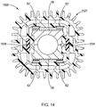
- the modular units 150a, 150b, 150c, 150d, 150f have structures similar to those shown in FIGS. 11A to 11F except that the modular units include thermal insulation jackets 152a, 152b, 152c, 152d, 152e, 152f having fins extending from outer surfaces.
- the thermal insulation jackets 152a, 152b, 152c, 152d, 152e, 152f define receiving spaces for receiving additional heating elements 154a, 154b, 154c, 154d, 154e, 154f therein.
- FIG. 14 is an enlarged view of the modular unit 150f of FIG. 13F .
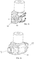
- FIGS. 15 to 17 show an application of the modular heater system as a valve heater.
- FIG. 15 shows the modular heater system is provided around a valve 15.
- the modular heater system disclosed in any of the embodiments of the present disclosure is bonded to an aluminum thermal transfer interface 198.
- FIGS. 16 and 17 show outer shells 199 are molded or vacuum formed around the modular heater system to enclose the fluid conduit 14 and the modular heater system therein.
- a modular heater system 200 includes a modular unit 202 and a pair of end caps 204 disposed at longitudinal ends of the modular unit 202.
- the modular unit 202 and the end caps 204 surround a fluid conduit (not shown) to be heated.
- the end caps 204 each have a plate portion 205 attached to the modular unit 202 and a tubular flange 208 protruding from the plate portion 205.
- the tubular flange 208 of the end cap 204 can fit into a recess of an adjacent modular unit (not shown) or an adjacent mounting structure (not shown) so as to connect the modular unit 204 to an adjacent modular unit or to an adjacent mounting structure.
- the modular unit 202 includes a carrier member 210, a thermal insulation jacket 212 surrounding the carrier member 210, and at least one heating element 214 disposed on at least one surface of the carrier member 210.
- the carrier member 210 includes an upper piece 216 and a lower piece 218 jointly defining a receiving space 220 for receiving a fluid conduit (not shown).
- the upper piece 216 and the lower piece 218 of the carrier member 210 are made of a metal, for example, aluminum, to diffuse heat from the heating element 214 to the fluid conduit received in the receiving space 220 to facilitate heat transfer from the heating element 214 to the fluid conduit.
- heating element 214 While only one heating element 214 is shown to be disposed on one surface of the carrier member 210, more than one heating element 214 may be disposed on more than one surface of the carrier member 210, for example, one heating element 214 on each of the upper piece 216 and the lower piece 218 of the carrier member 210.
- An air gap 222 is defined between the carrier member 210 and the thermal insulation jackets 212 and acts as a thermal break to keep the heat inside the thermal insulation jackets 212.
- the thermal insulation jacket 212 includes an upper portion 224 and a lower portion 226.
- the upper portion 224 and the lower portion 226 each define a substantially U-shape cross section and includes an upper wall 230, a pair of side walls 232 extending from opposing ends of the upper wall 230.
- the upper and lower portion 224 and 226 each have a pair of free ends 233 at the side walls 232.
- the free ends 233 are enlarged inwardly toward the carrier member 210 while maintaining a flat outer surface of the thermal insulation jacket.
- the side surfaces of the carrier member 210 opposing the enlarged free ends 233 have a slightly concave outer surface to accommodate the enlarged free ends 233.
- the free ends 233 may define either a protrusion 234 or a recess 236.
- the upper and lower portions 224, 226 of the thermal insulation jacket 212 each include a protrusion 234 at one side wall 232 and a recess 236 at the other side wall 232.
- the protrusions 234 and the recesses 236 of the upper and lower portions 224, 226 have complementary shapes such that the protrusion 234 at the upper half portion 224 can fit into an opposing recess 236 at the lower portion 226 and that the protrusion 234 at the lower portion 226 can fit into the opposing recess 236 at the upper portion 224. Therefore, the upper portion 224 and the lower portion 226 can be self-locked.
- the upper portion 224 may include a pair of protrusions 234 and the lower portion 226 may include a pair of recesses 236 or vice versa as long as the protrusions 234 can fit into corresponding recesses 236 to lock the upper and lower portions 224 and 226 of the thermal insulation jacket 212 together.
- the modular unit 202 further includes a plurality of shims 238 disposed across the air gap 222 to connect the carrier member 210 to the thermal insulation jackets 212 to maintain the air gap 222 between the carrier member 210 and the thermal insulation jackets 212.
- a fixed air gap may not be maintained between the upper portion 224 of the thermal insulation jacket 212 and the upper piece 216 of the carrier member 210 if no connecting component is used.
- the shims 238 can maintain a fixed air gap 222 between the upper piece 216 and the upper half portion 224 and between the lower piece 218 and the lower half portion 226 before the upper and lower portions 224 and 226 of the thermal insulation jacket 212 are locked together.
- the shims 238 may have a spring force and are elastic to facilitate mounting of the modular unit 202 around around the fluid conduit.
- the modular unit 202 may further include a conductor 240 and a bus bar 242 for connecting the heating element 214 to an external power terminal 244.
- the power terminals 244 extends through openings 246 (shown in FIG. 18 ) of the thermal insulation jacket 212, particularly the upper portion 232, to engage the bus bar 242.
- the power terminals 244 are connected to an external power supply via wires. Therefore, the wires are provided outside the modular unit 202, rather than inside the modular unit 202 to simplify the structure of the modular unit 202 and mounting of the modular unit 202 around the fluid conduit.
- a dielectric material 243 may be provided on a surface of the bus bar 242 facing the heating element 214 to keep the bus bar 242 in place and to electrically insulate the heating element 214 from the bus bar 242.
- Some of the openings through the thermal insulation jacket 212 may be in the form of elongated slots 248 to provide room for thermal expansion/contraction of the power terminals 244. Some of the openings 246 may be used for insertion of sensors (not shown). The openings for sensors do not need to be at the longitudinal ends of the modular unit 202, and may be located anywhere at the modular unit 202.
- a modular heater system 300 has a structure similar to that the modular heater system 200 of FIG. 18 and 19 except for the shapes of the carrier member and the thermal insulation jacket and the structure of the end caps. More specifically, the modular heater system 300 includes a modular unit 302 and a pair of end caps 304 at longitudinal ends of the modular unit 302. The end caps 304 each have a plate configuration defining a central opening 305 for receiving a corresponding tubular flange 208 of the end cap 204 of an adjacent modular heater system 200. Therefore, the modular heater system 200 of FIG. 18 can be secured to the modular heater system 300 of FIG. 20 by inserting the tubular flange 208 into the opening 305.
- the modular heater system 300 may have a first end cap 304 defining a central opening 305 and a second end cap 204 defining a tubular flange 208 depending on applications.
- the modular unit 302 has a substantially rectangular cross section.
- the modular unit 302 includes a carrier member 310 defining a receiving space 320 for receiving a fluid conduit, a thermal insulation jacket 312 surrounding the carrier member 310, a heating element (not shown) disposed on a surface of the carrier member 310, a conducting member 340, bus bars 342, power terminals 344, and a plurality of shims 338.
- the heating element is in contact with the conducting member 340 and is connected to an external power source (not shown) through the conducting member 340, the bus bars 342, and the power terminals 344.
- the thermal insulation jacket 312 includes an upper portion 324 and a lower portion 326 each defining a protrusion 334 and a recess 336. Therefore, the upper and lower half portions 324 and 326 of the thermal insulation jacket 312 can be locked together by fitting the protrusions 334 into the recesses 336.
- the free ends 333 of the upper and lower portions 324 and 326 of the thermal insulation jacket 312 are only slightly enlarged. Therefore, the carrier member 310 can have flat side outer surfaces without being recessed to accommodate the enlarged free ends 333.
- a modular heater system 400 may be used to heat a piping system having multiple fluid conduits 401 and having a complex configuration.
- the modular heater system 400 may include first modular units 402, a second modular unit 404 connecting between the first modular units 402, and a plurality of end caps 406 at opposing ends of the first and second modular units 402, 404.
- the first modular unit 402 and the second modular units 404 may have a structure similar to the modular unit 202 of FIG. 18 , or the modular unit 302 of FIG. 20 .
- the end caps 406 are configured to engage an adjacent modular unit, an adjacent end cap, or an adjacent mounting structure.
- the modular heater system 400 may further include a plurality of terminal blocks 408 mounted on outer surfaces of the modular units 402, 404.
- the end caps 406 each include a plate portion 410 and a protrusion 412 extending vertically from the plate portion 410.
- the plate portion 410 may be mounted to a longitudinal end surface of a second modular unit 404.
- the protrusion 412 may fit into a corresponding recess in a thermal jacket of a first modular unit 402. Therefore, the first and second modular units 402 and 404 can be connected together.
- a modular heater system 500 according to an eighth embodiment that is not in accordance with the invention is structurally similar to that of FIGS. 18 and 19 except for the shape of the thermal insulation jackets and the inclusion of baffle members.
- the modular heater system 500 includes a modular unit 502 and a pair of end caps 504.
- the end caps 504 each include a plate portion 506 and a tubular flange 508 extending from the plate portion 506.
- the modular unit 502 includes a carrier member 510, a thermal insulation jacket 512, a heating element (not shown) disposed on a surface of the carrier member 510, a conducting member 540, a bus bar 542, and a plurality of shims 538.
- An insulation material 543 may be provided on the bus bar 542 to secure the bus bar 542 to the thermal insulation jacket 512 and to electrically insulate the bus bar 542 from the heating element.
- the carrier member 510 is structurally similar to that of FIG. 19 and thus the detailed description thereof is omitted herein for clarity.
- the thermal insulation jacket 512 is structurally similar to the thermal insulation jacket 212 of FIG. 19 except that the free ends 533 of the upper and lower portions of the thermal insulation jacket 512 are enlarged both inwardly and outwardly such that the thermal insulation jacket 512 have a slightly convex side outer surfaces 548 and a slightly convex side inner surfaces 550.
- the carrier member 510 has slightly concave side outer surfaces 552 to accommodate the enlarged free ends 533 of the upper and lower portions of the thermal insulation jacket 512.
- the modular unit 502 further includes a baffle 560 in the form of polyimide sheet disposed in the air gap 522 to obstruct heat transfer from the carrier member 510 to the thermal insulation jacket 512.
- the air gap 522 may be filled with foam or an insulator of any form to obstruct heat transfer from the carrier member 510 to the thermal insulation jacket 512.
- a modular heater system 600 according to a ninth embodiment that is not in accordance with the invention has a structure similar to that of the modular heater system of previous embodiments except for the shapes of the carrier member 610 and the thermal insulation jacket 612, and the form of a variant of a bus bar.
- the modular heater systemt 600 includes a modular unit 602 and a pair of end caps 604.
- the modular unit 602 includes a carrier member 610, a thermal insulation jacket 612, at least one heating element 618, a conducting member 640, a first bus bar 641, a second bus bar 642.
- the first bus bar 641 is connected to the heating element 618 through the conducting member 640.
- the second bus bar 642 has a plate portion 643 and an extension portion 644.
- the extension potion 644 extends toward the heating element 618, is directly connected to the heating element 618, and has a curved shape to better accommodate a dielectric material (not shown) that may be disposed between the heating element 618 and the plate portion 643 of the second bus bar 642.
- the carrier member 610 is structurally similar to those disclosed in FIGS. 18 to 25 except that the upper and lower pieces of the carrier member 610 each have a pair of flanges 650 protruding from side surfaces of the upper and lower pieces.
- a plurality of shims 638 connect the flanges of the carrier member 610 to the enlarged free ends 633 of the upper and lower portions of the thermal insulation jacket 612.
- the thermal insulation jacket 612 is structurally similar to those disclosed in connection with FIGS. 18 to 25 except for the shape.
- the thermal insulation jacket 612 has upper and lower portions each defining a pair of free ends 633. The free ends are enlarged outwardly to define ear portions 660.
- the carrier member 610 is smaller so as to provide a larger air gap 622 between the carrier member 610 and the thermal insulation jacket 612.
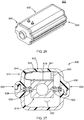
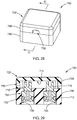
- a terminal box 700 in a first form may include a housing 702 and electrical connectors 704 disposed inside the housing 702.
- the housing 702 includes a base 706 and a cover 708.
- the base 706 and the cover 708 can be configured to be snapped together in place, or be connected by welding or any bonding methods known in the art.
- the base 706 defines first cavities 710.
- the cover 708 defines a second cavity 714 and a side opening 718.
- the side opening 718 is disposed adjacent one of the electrical connectors 704.
- the second cavity 714 is open to the side opening 718 and the first cavities 710.
- the connectors 704 are disposed in the first cavities 710 with O-rings 712 provided in the first cavities 710 to center and secure the connectors 704 in the first cavities 710.
- the connectors 704 each have an upper end 716 protruding into the second cavity 714.
- Lead wires (not shown) may be disposed in the second cavity 714 to connect the upper ends 716 of the electrical connectors 704 to an external power terminal (not shown) through the side opening 718.
- a variant of a terminal box 740 is shown to include a housing 742 and electrical connectors 744.
- the housing 742 includes a base 746 and a cover 748.
- the base 746 defines firs cavities 750 for receiving the electrical connectors 744.
- the cover 748 defines a second cavity 752 and a side opening 754.
- the second cavity 752 is open to the first cavities 750 and the side opening 754.
- the electrical connectors 744 are disposed in the first cavities 750 with O-rings 756 disposed in the firs cavities 750 to center and secure the electrical connectors 744 in the first cavities 750.
- Upper portions 758 of the electrical connectors 744 protrude into the first cavity 750.
- Wirings can be disposed in the second cavity 752 to engage an external power terminal through the side opening 754.
- the side opening 754 may be disposed between the electrical connectors 744.
- a terminal box 800 is structurally similar to those described in connection with FIGS. 28 to 31 except that the housing is configured to receive thermowells for receiving and protecting temperature sensors or other sensing devices such as by way of example, pressure sensors, strain sensor, and moisture sensors, among others.
- the terminal box 800 include a housing 802 having a cover 804 and a base 806.
- the base 806 defines first cavities 808.
- the cover 804 defines through holes 810 corresponding to the first cavities 808 to allow for insertion of temperature sensors 812 into the first cavities 808.
- the temperature sensors 812 may be a thermocouple, an RTD, or a thermistor.
- the cover 804 defines a side opening 814 into which a conductor or a terminal 816 may be disposed.
- the terminal box 800 further includes a plurality of thermowells 820 inserted into the corresponding first cavities 808 for receiving and protecting ends of the temperature sensors 812. Springs 824 may be disposed in the first cavities 808 to bias the thermowells 820 against a bottom wall of the base 806.
- the heater element (s) disposed inside the modular units may be easily connected to a power source by placing the terminal boxes on the outer surface of the modular unit and by connecting the electrical connectors of the terminal boxes to the electrical terminals 244 344 (shown in FIGS. 18-21 ). No wire is used inside the modular units so that mounting of the modular units around the fluid conduit can be made easy.
Landscapes
- Engineering & Computer Science (AREA)
- General Engineering & Computer Science (AREA)
- Mechanical Engineering (AREA)
- Pipe Accessories (AREA)
- Resistance Heating (AREA)
- Instantaneous Water Boilers, Portable Hot-Water Supply Apparatuses, And Control Of Portable Hot-Water Supply Apparatuses (AREA)
Description
- This application claims priority to
U.S. Provisional Application No. 62/267,937 - The present disclosure relates generally to electric heaters for use in pipelines, and more particularly to electric heaters for use in gaslines and pumplines such as, by way of example, semiconductor processing systems.
- The statements in this section merely provide background information related to the present disclosure and may not constitute prior art.
- The supply of fluids such as oil, gas, and water, among others, from a supply, e.g., an oil well or a water reservoir, requires transfer of such fluids by conduits or the like. Maintaining a free or unrestricted flow of the fluids within the conduits is often necessary, in addition to maintaining the fluid at or above a certain temperature. Presently, an electric heater in the form of a cable or a tape, known in the art as a "heat trace," is commonly used around the conduits to provide heat to the conduits and thus to the fluids. Additionally, the conduits and the heat traces are sometimes surrounded by a thermal insulation jacket to reduce heat loss to the surrounding environment. Such conduits and heat traces surrounded by a thermal insulation jacket have been disclosed in
US 2009/016707 ,WO 2007/019564 andUS 4,429,213 . - Heat trace cables are a popular means for heating such fluid conduits due to their relative simplicity and low cost. Generally, heat trace cables are disposed along the length of the conduits or wrapped around the conduits and are fastened at regular intervals with bands, retaining straps or any other suitable fasteners, as shown in
U.S. Patent No. 5,294,780 to Montierth et al. ,U.S. Patent No. 5,086,836 to Barth et al. ,U.S. Patent No. 4,791,277 to Montierth et al. ,U.S. Patent No. 4,152,577 to Leavines ,U.S. Patent No. 4,123,837 to Horner ,U.S. Patent No. 3,971,416 to Johnson , andU.S. Patent Reissue No. 29,332 to Bilbro . Fastening heat trace cables to the pipe or conduit has proven to be time consuming and burdensome, particularly for replacement of utility lines and continuous manufacturing processes, among others, where time is of the essence. - To expedite the replacement of utility lines,
U.S. Patent No. 6,792,200 proposes a pre-fabricated heat-traced pipe, wherein a pipe to be heated, a heat trace, and a connector for electrically connecting the heat trace to a power source are cured and integrally formed beforehand and inventoried before a need for replacing an old pipe arises. While this prefabricated pipe saves some time with respect to replacement of utility lines, it requires a custom-made heat-traced pipe, thereby increasing undesirable inventory space and manufacturing and maintenance costs. - The invention relates to a module heater unit according to independent claim 1.
- Further areas of applicability will become apparent from the description provided herein. It should be understood that the description and specific examples are intended for purposes of illustration only and are not intended to limit the scope of the present disclosure.
- The present disclosure will become more fully understood from the detailed description and the accompanying drawings, wherein:
-
FIG. 1 is a perspective view of a modular heater system constructed in accordance with a first embodiment of the present disclosure, wherein a portion of the interior of the modular heater system is shown; -
FIG. 2 is a perspective, cross-sectional view of a modular heater system constructed in accordance with the first embodiment of the present disclosure; -
FIG. 3 is a cross-sectional view of a modular heater system taken along line A-A ofFIG. 1 ; -
FIG. 4 is a plan view of a plurality of heating elements used in a modular heater system constructed in accordance with the teachings of the present disclosure; -
FIG. 5 is a perspective, cross-sectional view of a modular heater system constructed in accordance with a second embodiment of the present disclosure; -
FIG. 6 is another perspective, cross-sectional view of a modular heater system according to the second embodiment of the present disclosure, wherein an upper half body of a thermal insulation jacket is removed to expose the interior of the modular heater system; -
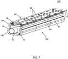
FIG. 7 is a perspective view of a modular heater system constructed in accordance with a third embodiment of the present disclosure; -
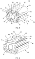
FIG. 8 is a perspective view of modular units of various forms, wherein the carrier members have a two-piece structure and the thermal insulation jackets have smooth surfaces, according to a fourth embodiment of the present disclosure; -
FIG. 9 is a perspective view of modular units of various forms, wherein the carrier members have a two-piece structure and the thermal insulation jackets having finned surfaces; -
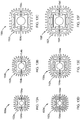
FIGS. 10A to 10F are side views of the various modular units ofFIG. 8 ; -
FIG. 11 is an enlarged view of the modular unit ofFIG. 10F ; -
FIG. 12A is a perspective view of an additional heating element disposed in a receiving space of the thermal insulation jacket of a modular unit; -
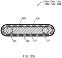
FIG. 12B is a cross-sectional view of the additional heating element taken along line B-B ofFIG. 12A ; -
FIGS. 13A to 13F are side views of the various modular units ofFIG. 9 ; -
FIG. 14 is an enlarged view of the modular unit ofFIG. 13F ; and -
FIG. 15 is a view showing an application of the modular heater system in a valve system constructed in accordance with the teachings of the present disclosure; -
FIG. 16 is a perspective view of the valve system wherein a portion of shells of the valve system is removed to expose the modular heater system inside; -
FIG. 17 is a cross-sectional view of the valve system wherein a modular heater system constructed in accordance with the teachings of the present disclosure is assembled, taken along line B-B ofFIG. 16 ; -
FIG. 18 is a perspective view of a modular heater system that is not in accordance with the invention; -
FIG. 19 is a cross-sectional view of the modular heater system ofFIG. 18 , taken along line C-C ofFIG. 18 ; -
FIG. 20 is a perspective view of a modular heater system that is not in accordance with the invention; -
FIG. 21 is a cross-sectional view of a modular heater system ofFIG. 20 ; -
FIG. 22 is a perspective view of a modular heater system, which is not in accordance with the invention, including a plurality of modular units that can be assembled to a piping system having a complex geometry; -
FIG. 23 is a cross-sectional view of the modular heater system and piping system ofFIG. 22 ; -
FIG. 24 is a perspective view of a modular heater system that is not in accordance with the invention; -
FIG. 25 is a cross-sectional view of the modular heater system ofFIG. 24 ; -
FIG. 26 is a perspective view of a modular heater system that is not in accordance with the invention; -
FIG. 27 is a cross-sectional view of a modular heater system ofFIG. 26 ; -
FIG. 28 is a perspective view of a terminal box shown inFIG. 22 ; -
FIG. 29 is a cross-sectional view of a terminal box ofFIG. 28 , taken along line D-D ofFIG. 28 ; -
FIG. 30 is a perspective view of a variant of a terminal box; -
FIG. 31 is a cross-sectional view of a terminal box ofFIG. 30 , taken along line E-E ofFIG. 30 ; -
FIG. 32 is a perspective view of another variant of a terminal box, through which temperature sensors are inserted; and -
FIG. 33 is a cross-sectional view of a terminal box ofFIG. 32 , taken along line F-F ofFIG. 32 . - Corresponding reference numerals indicate corresponding parts throughout the several views of the drawings.
- The following description is merely exemplary in nature and is not intended to limit the present disclosure, application, or uses.
- The structure of a heater in accordance with the present disclosure is now described in greater detail. At the outset, it should be understood that the word "conduit" as used throughout this specification includes, without limitation, tubes, pipes, and other enclosed or partially enclosed members for the transfer of fluids or other materials such as powders or slurries. The materials carried by the conduits described herein includes solids, liquids, and gases and may include, by way of example, fluids that are transferred within a semiconductor processing apparatus. The following description of the various forms with reference to such a semiconductor processing apparatus is merely exemplary in nature and is in no way intended to limit the disclosure, its application, or uses. Accordingly, the teachings of the present disclosure are not limited to a semiconductor processing apparatus and can be applied to any system of conduits while remaining within the scope of the present disclosure.
- Referring to
FIGS. 1 and 2 , amodular heater system 10 includes a plurality ofmodular units 12 aligned along a longitudinal direction X of afluid conduit 14 for heating a fluid contained therein. Threemodular units 12 are shown inFIG. 1 , whereas fourmodular units 12 are shown inFIG. 2 . The number of themodular units 12 depends on the length of thefluid conduit 14 to be heated. - The
modular units 12 each include acarrier member 16 surrounding thefluid conduit 14, aheating element 18 disposed on thecarrier member 16, aconductor 20 disposed on and contacting theheating element 18, an inner insulatingmaterial 22, and athermal insulation jacket 24 enclosing thefluid conduit 14, thecarrier member 16, theheating element 18, theconductor 20, and the inner insulatingmaterial 22 therein. Thethermal insulation jacket 24 define through holes corresponding to locations of theconductors 20 such that a plurality of conductingpins 26 can be inserted into the through holes of thethermal insulation jacket 24 to connect theheating element 18, theconductors 20 to an external power source (not shown). - Referring to
FIG. 3 , thecarrier member 16 has a substantially inverted U shape and includes anupper wall 30, and a pair ofside walls 32 extending vertically and downwardly from theupper wall 30. Theupper wall 30 and the pair ofside walls 32 jointly form a circularinner surface 34 defining a receivingspace 36 for receiving thefluid conduit 14 therein. The circularinner surface 34 substantially conforms to the shape of thefluid conduit 14 so that when thefluid conduit 14 is disposed in the receivingspace 36, thefluid conduit 14 contacts the circularinner surface 34 of thecarrier member 16. Theside walls 32 of thecarrier member 16 each define aside slot 38 recessed from anouter surface 40 of theside walls 32. Theupper wall 30 of thecarrier member 16 may define a guidedslot 42 for receiving theheating element 18 therein. - The
carrier member 16 is made of a thermally conducting material to conduct heat transfer from theheating element 18 to thefluid conduit 14. Preferably, thecarrier member 16 is made of a metal having good thermal conductivity. In the present embodiment, thecarrier member 16 may have an elongated shape and formed as a single piece component. Thecarrier member 16 is provided around thefluid conduit 14 to help mounting of theheating element 18 on thecarrier member 16 and mounting of thethermal insulation jacket 24 around thecarrier member 16. Thecarrier member 16 has the function of supporting theheating element 18 thereon, diffusing heat from theheating element 18 to thefluid conduit 14, and securing thethermal insulation jacket 24 around thecarrier member 16. - Referring to
FIG. 4 , theheating elements 18 may include anelongated plate body 44 on which resistive heating circuits are formed, which in this exemplary form are a thick film resistive heaters, and a pair of power busses 46 disposed along the longitudinal sides of theelongated plate body 44. Theheating elements 18 may take any form as long as it can be disposed in the guidedslot 42 of thecarrier member 16. - Referring back to
FIG. 3 , thethermal insulation jacket 24 includes anupper half portion 50 and alower half portion 52, each defining a pair of lockingflanges 54 at opposing longitudinal sides to allow for self-locking around thecarrier member 16 by inserting the lockingflanges 54 into theside slots 38 of thecarrier member 16. - Optionally, another heating element may be disposed in each of the
side slots 38 of thecarrier member 16 as indicated byreference number 45, if necessary and if theside slots 38 are formed to have sufficient depth to accommodate both theoptional heating element 45 and the lockingflanges 54 of thethermal insulation jacket 24. - The insulating
material 22 is disposed between theheating element 18 and theupper half portion 50 and between a lower end of thecarrier member 16 and thelower half portion 52 of thethermal insulation jacket 24 to further thermally insulate thefluid conduit 14 andheating element 18 against heat transfer to thethermal insulation jacket 24. - As clearly shown in
FIG. 2 , thecarrier members 16 may each define at least onealignment hole 56 extending along the longitudinal direction X of thecarrier member 16. When a plurality ofmodular units 12 are disposed, the alignment holes 56 ofdifferent carrier members 16 are aligned. Analignment rod 60 may be inserted through the alignment holes 56 of themodular units 12 to connect themodular units 12 together and maintain alignment of the plurality ofmodular units 12. - Referring to
FIG. 5 , amodular unit 70 according to a second embodiment of the present disclosure is shown to be structurally similar to themodular unit 12 ofFIGS. 1 to 3 with modifications. In the present embodiment, like components are indicated by like reference numerals and the description thereof is omitted herein for clarity. - The
modular unit 70 includes acarrier member 76 surrounding thefluid conduit 14, aheating element 18 disposed on thecarrier member 76, at least one conductingmember 80 disposed on theheating element 18, and athermal insulation jacket 84 enclosing thefluid conduit 14, thecarrier member 76, theheating element 18, the conductingmember 80 therein. Theheating element 18 has the similar structure of that ofFIGS. 1 to 3 . - Similar to the
carrier member 16 of theFIGS. 1 to 3 , thecarrier member 76 includes anupper wall 90, and a pair ofside walls 92 extending vertically and downwardly from theupper wall 90. Theupper wall 90 and theside walls 92 jointly define a receiving space for receiving thefluid conduit 14. Theupper wall 90 of thecarrier member 76 has an upperflat surface 94 on which theheating element 18 is disposed. As in thecarrier member 16 ofFIGS. 1 to 3 , theside walls 92 of thecarrier member 76 each define aside slot 38. - The
thermal insulation jacket 84 includes anupper half portion 94 and alower half portion 96. Theupper half portion 94 includes a pair ofgrooves 98 recessed from an inner surface of theupper half portion 94. Thelower half portion 94 includes a protrudingportion 99 extending from an inner surface of thelower half portion 94 toward thefluid conduit 14. The protrudingportion 99 may also contact thefluid conduit 14 to help support thefluid conduit 14 in the receiving space of thecarrier member 76. Theupper half portion 94 and thelower half portion 96 each includeair pockets 95, which reduce heat losses through thethermal insulation jacket 84. - Referring to
FIG. 6 , the conducting member 80 (or internal bussing) includes a pair of conductingplates 82 oppose the longitudinal sides of theheating element 18. The conductingplates 82 are received in thegrooves 98 of theupper half portion 94 of thethermal insulation jacket 84. The conductingplates 82 each define a plurality offlexible arms 86 extending downwardly to contact the power busses 46 of theheating element 18. The conductingplates 82 define a plurality ofholes 88 aligned with theholes 89 in theupper half portion 94 of thethermal insulation jacket 84. Conducting pins (not shown) may be inserted through theholes 88 of the conductingplates 82 and theholes 89 ofthermal insulation jacket 84 to engage the conductingplates 82 such that power can be supplied from an external power source, through the conducting pin (not shown), the conductingplates 82, theflexible arms 86, the power busses 46, to the resistive heating circuits on theheating element 18. - While not shown in
FIGS. 5 and 6 , an insulating material may be provided between theheating element 18 and the conductingmember 80 to electrically insulate theheating element 18 from the conductingmember 80. - Referring to
FIG. 7 , amodular unit 100 according to a third embodiment of the present disclosure is structurally similar to the modular unit ofFIGS. 5 and 6 differing in that themodular unit 100 is longer and thethermal insulation jacket 102 has a relatively lower profile. - More specifically, the
modular unit 100 includes acarrier member 76 surrounding thefluid conduit 14, aheating element 18 disposed on thecarrier member 76, a conductingmember 80 disposed above theheating element 18, and athermal insulation jacket 102 enclosing thefluid conduit 14, thecarrier member 76, theheating element 18, the conductingmember 80 therein. The conductingmember 80 includes a pair of conductingplates 82 and a plurality of engagingarms 86 engaging the power busses 46 of theheating element 18. - The
thermal insulation jacket 102 includes an upperhalf part 106 and a lowerhalf part 108. The lowerhalf part 108 includes a protrudingportion 110 protruding toward thefluid conduit 14 to help support thefluid conduit 14 in the receiving space of thecarrier member 76. Unlike the lower half part of thethermal insulation jacket 24 ofFIGS. 1 to 3 , the lower half part of thethermal insulation jacket 102 of the present embodiment does not have any space for receiving an inner insulatingmaterial 22 and has a smaller thickness than that of the first and second embodiments. Therefore, the outer profile of thethermal insulation jacket 102 can be made smaller. - The modular construction of the heater system according to the teachings of the present disclosure provides a relatively low cost heater system that can be easily adapted to a conduit system. The
modular units fluid conduit 14 and are scalable. No wiring is provided inside themodular units modular units fluid conduit 14 to improve aesthetics. Analignment rod 60 can be inserted into the alignment holes of the carrier members to integrate the plurality ofmodular units - Referring to 8 and 9, the modular units according to a fourth embodiment may have a variety of forms according to the teachings of the present disclosure.
FIG. 8 shows various forms of modular units including thermal insulation jackets having smooth outer surfaces.FIG. 9 shows various forms of modular units including thermal insulation jackets having finned surfaces for a more touch safe operation. - In
FIGS. 8 and 9 , the carrier members each have two identical pieces, rather than a one-piece component as shown in the first, second and third embodiments. Each piece can have an upper wall for supporting a heating element similar to that shown in any of the first to third embodiments, whether it is a guided slot as shown in the first embodiment or an upper flat surface as shown in the second and third embodiments. Therefore, the carrier member, having two identical pieces, can be configured to carry twoheating elements 18 for higher performance applications. - Referring to
FIGS. 10A to 10F , themodular units upper piece lower piece upper piece lower piece heating elements 18. The upper piece and the lower piece of each carrier member jointly define the side slots on the side walls for receiving locking flanges of thethermal insulation jacket thermal insulation jackets latching elements -
FIG. 11 is an enlarged view of themodular unit 120f ofFIG. 10F , wherein themodular unit 120f includes a carrier member including anupper piece 122f and alower piece 124f,heating elements 18 disposed on the upper and lower sides of carrier member, particularly the upper side of theupper piece 122f and the lower side of thelower piece 124f, and latchingelements 130f on the right and left sides of the carrier member within the receivingspaces 132f defined by thethermal insulation jacket 128f. Thethermal insulation jacket 128f defines a plurality ofair pockets 129, which act as good thermal insulator to further reduce heat loss from the carrier member to thethermal insulation jacket 128f. - Referring to
FIGS. 12A and12B , theheating elements 18 may be in the form of a heat trace cable. The heat trace cable typically includes a pair of bus-conductors 222, which are surrounded by asemiconductive polymer material 224 that functions as a heating element. A dielectric orinsulator material 226 surrounds thesemiconductive polymer material 224, which may optionally be surrounded by ametal braid material 228 as shown for additional functionality such as a ground plane. Further, anouter jacket 230 surrounds themetal braid material 228 to protect the overall assembly, and theouter jacket 230 is typically an insulating material such as a thermoplastic. - The
heating elements 18 may be any form of heater, including but not limited to a layered heater such as those disclosed inU.S. Patent No. 8,680,443 , which is commonly assigned with the present application and the contents of which are incorporated herein by reference in their entirety. Theheating elements 18 may also be resistive elements embedded in any substrate/insulation such as by way of example flexible insulated heaters as disclosed inU.S. Patent No. 5,714,738 , which is also commonly assigned with the present application and the contents of which are incorporated herein by reference in their entirety. - Referring to
FIGS. 13A to 13F , themodular units FIGS. 11A to 11F except that the modular units includethermal insulation jackets thermal insulation jackets additional heating elements FIG. 14 is an enlarged view of themodular unit 150f ofFIG. 13F . -
FIGS. 15 to 17 show an application of the modular heater system as a valve heater.FIG. 15 shows the modular heater system is provided around avalve 15. The modular heater system disclosed in any of the embodiments of the present disclosure is bonded to an aluminumthermal transfer interface 198.FIGS. 16 and17 showouter shells 199 are molded or vacuum formed around the modular heater system to enclose thefluid conduit 14 and the modular heater system therein. - Referring to
FIG. 18 , amodular heater system 200 according to a fifth embodiment that is not in accordance with the invention includes amodular unit 202 and a pair ofend caps 204 disposed at longitudinal ends of themodular unit 202. Themodular unit 202 and the end caps 204 surround a fluid conduit (not shown) to be heated. The end caps 204 each have aplate portion 205 attached to themodular unit 202 and atubular flange 208 protruding from theplate portion 205. Thetubular flange 208 of theend cap 204 can fit into a recess of an adjacent modular unit (not shown) or an adjacent mounting structure (not shown) so as to connect themodular unit 204 to an adjacent modular unit or to an adjacent mounting structure. - Referring to
FIG. 19 , themodular unit 202 includes acarrier member 210, athermal insulation jacket 212 surrounding thecarrier member 210, and at least oneheating element 214 disposed on at least one surface of thecarrier member 210. Thecarrier member 210 includes anupper piece 216 and alower piece 218 jointly defining a receivingspace 220 for receiving a fluid conduit (not shown). Theupper piece 216 and thelower piece 218 of thecarrier member 210 are made of a metal, for example, aluminum, to diffuse heat from theheating element 214 to the fluid conduit received in the receivingspace 220 to facilitate heat transfer from theheating element 214 to the fluid conduit. While only oneheating element 214 is shown to be disposed on one surface of thecarrier member 210, more than oneheating element 214 may be disposed on more than one surface of thecarrier member 210, for example, oneheating element 214 on each of theupper piece 216 and thelower piece 218 of thecarrier member 210. Anair gap 222 is defined between thecarrier member 210 and thethermal insulation jackets 212 and acts as a thermal break to keep the heat inside thethermal insulation jackets 212. - The
thermal insulation jacket 212 includes anupper portion 224 and alower portion 226. Theupper portion 224 and thelower portion 226 each define a substantially U-shape cross section and includes anupper wall 230, a pair ofside walls 232 extending from opposing ends of theupper wall 230. The upper andlower portion side walls 232. The free ends 233 are enlarged inwardly toward thecarrier member 210 while maintaining a flat outer surface of the thermal insulation jacket. The side surfaces of thecarrier member 210 opposing the enlarged free ends 233 have a slightly concave outer surface to accommodate the enlarged free ends 233. - The free ends 233 may define either a
protrusion 234 or arecess 236. As an example, the upper andlower portions thermal insulation jacket 212 each include aprotrusion 234 at oneside wall 232 and arecess 236 at theother side wall 232. Theprotrusions 234 and therecesses 236 of the upper andlower portions protrusion 234 at theupper half portion 224 can fit into an opposingrecess 236 at thelower portion 226 and that theprotrusion 234 at thelower portion 226 can fit into the opposingrecess 236 at theupper portion 224. Therefore, theupper portion 224 and thelower portion 226 can be self-locked. Alternatively, theupper portion 224 may include a pair ofprotrusions 234 and thelower portion 226 may include a pair ofrecesses 236 or vice versa as long as theprotrusions 234 can fit into correspondingrecesses 236 to lock the upper andlower portions thermal insulation jacket 212 together. - The
modular unit 202 further includes a plurality ofshims 238 disposed across theair gap 222 to connect thecarrier member 210 to thethermal insulation jackets 212 to maintain theair gap 222 between thecarrier member 210 and thethermal insulation jackets 212. Before theupper portion 224 of thethermal insulation jacket 212 is secured to thelower portion 226 of thethermal insulation jacket 212 by fitting the theprotrusions 234 into therecesses 236, a fixed air gap may not be maintained between theupper portion 224 of thethermal insulation jacket 212 and theupper piece 216 of thecarrier member 210 if no connecting component is used. Similarly, a fixed air gap may not be maintained between thelower half portion 226 of thethermal insulation jacket 212 and thelower piece 218 of thecarrier member 210 if no connecting component is used. Therefore, theshims 238 can maintain a fixedair gap 222 between theupper piece 216 and theupper half portion 224 and between thelower piece 218 and thelower half portion 226 before the upper andlower portions thermal insulation jacket 212 are locked together. Theshims 238 may have a spring force and are elastic to facilitate mounting of themodular unit 202 around around the fluid conduit. - The
modular unit 202 may further include aconductor 240 and abus bar 242 for connecting theheating element 214 to anexternal power terminal 244. Thepower terminals 244 extends through openings 246 (shown inFIG. 18 ) of thethermal insulation jacket 212, particularly theupper portion 232, to engage thebus bar 242. Thepower terminals 244 are connected to an external power supply via wires. Therefore, the wires are provided outside themodular unit 202, rather than inside themodular unit 202 to simplify the structure of themodular unit 202 and mounting of themodular unit 202 around the fluid conduit. Adielectric material 243 may be provided on a surface of thebus bar 242 facing theheating element 214 to keep thebus bar 242 in place and to electrically insulate theheating element 214 from thebus bar 242. - Some of the openings through the
thermal insulation jacket 212 may be in the form ofelongated slots 248 to provide room for thermal expansion/contraction of thepower terminals 244. Some of theopenings 246 may be used for insertion of sensors (not shown). The openings for sensors do not need to be at the longitudinal ends of themodular unit 202, and may be located anywhere at themodular unit 202. - Referring to
FIGS. 20 and 21 , amodular heater system 300 according to a sixth embodiment that is not in accordance with the invention has a structure similar to that themodular heater system 200 ofFIG. 18 and 19 except for the shapes of the carrier member and the thermal insulation jacket and the structure of the end caps. More specifically, themodular heater system 300 includes amodular unit 302 and a pair ofend caps 304 at longitudinal ends of themodular unit 302. The end caps 304 each have a plate configuration defining acentral opening 305 for receiving a correspondingtubular flange 208 of theend cap 204 of an adjacentmodular heater system 200. Therefore, themodular heater system 200 ofFIG. 18 can be secured to themodular heater system 300 ofFIG. 20 by inserting thetubular flange 208 into theopening 305. Themodular heater system 300 may have afirst end cap 304 defining acentral opening 305 and asecond end cap 204 defining atubular flange 208 depending on applications. Themodular unit 302 has a substantially rectangular cross section. - More specifically, the
modular unit 302 includes acarrier member 310 defining a receivingspace 320 for receiving a fluid conduit, athermal insulation jacket 312 surrounding thecarrier member 310, a heating element (not shown) disposed on a surface of thecarrier member 310, a conductingmember 340, bus bars 342,power terminals 344, and a plurality ofshims 338. The heating element is in contact with the conductingmember 340 and is connected to an external power source (not shown) through the conductingmember 340, the bus bars 342, and thepower terminals 344. - As in the fifth embodiment, the
thermal insulation jacket 312 includes anupper portion 324 and alower portion 326 each defining aprotrusion 334 and arecess 336. Therefore, the upper andlower half portions thermal insulation jacket 312 can be locked together by fitting theprotrusions 334 into therecesses 336. - Unlike the
thermal insulation jacket 212 in the fifth embodiment, the free ends 333 of the upper andlower portions thermal insulation jacket 312 are only slightly enlarged. Therefore, thecarrier member 310 can have flat side outer surfaces without being recessed to accommodate the enlarged free ends 333. - Referring to
FIG. 22 , amodular heater system 400 according to a seventh embodiment that is not in accordance with the invention may be used to heat a piping system having multiplefluid conduits 401 and having a complex configuration. Themodular heater system 400 may include firstmodular units 402, a secondmodular unit 404 connecting between the firstmodular units 402, and a plurality ofend caps 406 at opposing ends of the first and secondmodular units modular unit 402 and the secondmodular units 404 may have a structure similar to themodular unit 202 ofFIG. 18 , or themodular unit 302 ofFIG. 20 . The end caps 406 are configured to engage an adjacent modular unit, an adjacent end cap, or an adjacent mounting structure. Themodular heater system 400 may further include a plurality ofterminal blocks 408 mounted on outer surfaces of themodular units - Referring to
FIG. 23 , the end caps 406 each include aplate portion 410 and aprotrusion 412 extending vertically from theplate portion 410. Theplate portion 410 may be mounted to a longitudinal end surface of a secondmodular unit 404. Theprotrusion 412 may fit into a corresponding recess in a thermal jacket of a firstmodular unit 402. Therefore, the first and secondmodular units - Referring to
FIGS. 24 and 25 , amodular heater system 500 according to an eighth embodiment that is not in accordance with the invention is structurally similar to that ofFIGS. 18 and 19 except for the shape of the thermal insulation jackets and the inclusion of baffle members. - More specifically, the
modular heater system 500 includes amodular unit 502 and a pair ofend caps 504. The end caps 504 each include aplate portion 506 and atubular flange 508 extending from theplate portion 506. Themodular unit 502 includes acarrier member 510, athermal insulation jacket 512, a heating element (not shown) disposed on a surface of thecarrier member 510, a conductingmember 540, abus bar 542, and a plurality ofshims 538. Aninsulation material 543 may be provided on thebus bar 542 to secure thebus bar 542 to thethermal insulation jacket 512 and to electrically insulate thebus bar 542 from the heating element. Thecarrier member 510 is structurally similar to that ofFIG. 19 and thus the detailed description thereof is omitted herein for clarity. - The
thermal insulation jacket 512 is structurally similar to thethermal insulation jacket 212 ofFIG. 19 except that the free ends 533 of the upper and lower portions of thethermal insulation jacket 512 are enlarged both inwardly and outwardly such that thethermal insulation jacket 512 have a slightly convex sideouter surfaces 548 and a slightly convex sideinner surfaces 550. Thecarrier member 510 has slightly concave sideouter surfaces 552 to accommodate the enlarged free ends 533 of the upper and lower portions of thethermal insulation jacket 512. Themodular unit 502 further includes abaffle 560 in the form of polyimide sheet disposed in theair gap 522 to obstruct heat transfer from thecarrier member 510 to thethermal insulation jacket 512. Alternately, theair gap 522 may be filled with foam or an insulator of any form to obstruct heat transfer from thecarrier member 510 to thethermal insulation jacket 512. - Referring to
FIGS. 26 and 27 , amodular heater system 600 according to a ninth embodiment that is not in accordance with the invention has a structure similar to that of the modular heater system of previous embodiments except for the shapes of thecarrier member 610 and thethermal insulation jacket 612, and the form of a variant of a bus bar. - More specifically, the
modular heater systemt 600 includes amodular unit 602 and a pair ofend caps 604. Themodular unit 602 includes acarrier member 610, athermal insulation jacket 612, at least oneheating element 618, a conductingmember 640, afirst bus bar 641, asecond bus bar 642. Thefirst bus bar 641 is connected to theheating element 618 through the conductingmember 640. Thesecond bus bar 642 has aplate portion 643 and anextension portion 644. Theextension potion 644 extends toward theheating element 618, is directly connected to theheating element 618, and has a curved shape to better accommodate a dielectric material (not shown) that may be disposed between theheating element 618 and theplate portion 643 of thesecond bus bar 642. Thecarrier member 610 is structurally similar to those disclosed inFIGS. 18 to 25 except that the upper and lower pieces of thecarrier member 610 each have a pair offlanges 650 protruding from side surfaces of the upper and lower pieces. A plurality ofshims 638 connect the flanges of thecarrier member 610 to the enlarged free ends 633 of the upper and lower portions of thethermal insulation jacket 612. - The
thermal insulation jacket 612 is structurally similar to those disclosed in connection withFIGS. 18 to 25 except for the shape. Thethermal insulation jacket 612 has upper and lower portions each defining a pair of free ends 633. The free ends are enlarged outwardly to defineear portions 660. - In the present embodiment, the
carrier member 610 is smaller so as to provide alarger air gap 622 between thecarrier member 610 and thethermal insulation jacket 612. - Referring to
FIGS. 28 and 29 , the terminal boxes as shown inFIG. 22 will be explained in more detail below. Aterminal box 700 in a first form may include ahousing 702 andelectrical connectors 704 disposed inside thehousing 702. Thehousing 702 includes abase 706 and acover 708. Thebase 706 and thecover 708 can be configured to be snapped together in place, or be connected by welding or any bonding methods known in the art. Thebase 706 definesfirst cavities 710. Thecover 708 defines asecond cavity 714 and aside opening 718. Theside opening 718 is disposed adjacent one of theelectrical connectors 704. Thesecond cavity 714 is open to theside opening 718 and thefirst cavities 710. Theconnectors 704 are disposed in thefirst cavities 710 with O-rings 712 provided in thefirst cavities 710 to center and secure theconnectors 704 in thefirst cavities 710. Theconnectors 704 each have anupper end 716 protruding into thesecond cavity 714. Lead wires (not shown) may be disposed in thesecond cavity 714 to connect the upper ends 716 of theelectrical connectors 704 to an external power terminal (not shown) through theside opening 718. - Referring to
FIGS. 30 and 31 , a variant of aterminal box 740 is shown to include ahousing 742 andelectrical connectors 744. Thehousing 742 includes abase 746 and acover 748. Thebase 746 definesfirs cavities 750 for receiving theelectrical connectors 744. Thecover 748 defines asecond cavity 752 and aside opening 754. Thesecond cavity 752 is open to thefirst cavities 750 and theside opening 754. Theelectrical connectors 744 are disposed in thefirst cavities 750 with O-rings 756 disposed in thefirs cavities 750 to center and secure theelectrical connectors 744 in thefirst cavities 750.Upper portions 758 of theelectrical connectors 744 protrude into thefirst cavity 750. Wirings can be disposed in thesecond cavity 752 to engage an external power terminal through theside opening 754. Theside opening 754 may be disposed between theelectrical connectors 744. - Referring to
FIGS. 32 and 33 , another variant of aterminal box 800 is structurally similar to those described in connection withFIGS. 28 to 31 except that the housing is configured to receive thermowells for receiving and protecting temperature sensors or other sensing devices such as by way of example, pressure sensors, strain sensor, and moisture sensors, among others. More specifically, theterminal box 800 include ahousing 802 having acover 804 and abase 806. Thebase 806 definesfirst cavities 808. Thecover 804 defines throughholes 810 corresponding to thefirst cavities 808 to allow for insertion oftemperature sensors 812 into thefirst cavities 808. Thetemperature sensors 812 may be a thermocouple, an RTD, or a thermistor. Thecover 804 defines aside opening 814 into which a conductor or a terminal 816 may be disposed. Theterminal box 800 further includes a plurality ofthermowells 820 inserted into the correspondingfirst cavities 808 for receiving and protecting ends of thetemperature sensors 812.Springs 824 may be disposed in thefirst cavities 808 to bias thethermowells 820 against a bottom wall of thebase 806. - By using the
terminal boxes electrical terminals 244 344 (shown inFIGS. 18-21 ). No wire is used inside the modular units so that mounting of the modular units around the fluid conduit can be made easy.
Claims (9)
- A modular heater unit (12, 70, 100, 120a, 120b, 120c, 120d, 120e, 120f, 150a, 150b, 150c, 150d, 150e, 150f), comprising:a carrier member (16, 76) defining a receiving space (36) for receiving a fluid conduit (14);a heating element (18) disposed on a surface of the carrier member (16); anda thermal insulation jacket (24, 84, 102, 128a, 128b, 128c, 128d, 128e, 128f, 152a, 152b, 152c, 152d, 152e, 152f) surrounding the carrier member (16, 76), the thermal insulation jacket including an upper portion (50, 94, 106) and a lower portion (52, 96, 108),wherein the upper and lower portions have mating features (54) for securing the upper and lower portions together,
the modular heater unit (12) being characterized in that the carrier member (16) includes slots (38) for receiving the mating features (54) of the upper and lower portions of the thermal insulation jacket (24, 84, 102, 128a, 128b, 128c, 128d, 128e, 128f, 152a, 152b, 152c, 152d, 152e, 152f) therein, the mating features each defining a pair of locking flanges (54) at opposing longitudinal sides to allow for self-locking about the carrier member (16) such that the thermal insulation jacket is secured around the carrier member by inserting the locking flanges (54) into the slots (38) of the carrier member (16, 76). - The modular heater unit (12, 70, 100, 120a, 120b, 120c, 120d, 120e, 120f, 150a, 150b, 150c, 150d, 150e, 150f) according to Claim 1, wherein an air gap is defined between the carrier member and the thermal insulation jacket.
- The modular heater unit (12, 70, 100, 120a, 120b, 120c, 120d, 120e, 120f, 150a, 150b, 150c, 150d, 150e, 150f) according to Claim 2, further comprising an insulation material (22) in the air gap.
- The modular heater unit (12, 70, 100, 120a, 120b, 120c, 120d, 120e, 120f, 150a, 150b, 150c, 150d, 150e, 150f, 202, 302, 402, 502, 602) according to Claim 1, wherein the carrier member includes an upper piece (122a, 122b, 122c, 122d, 122e, 122f) and a lower piece (124a, 124b, 124c,124d, 124e, 124f), wherein the upper piece and the lower piece jointly define the receiving space (36) for receiving the fluid conduit (14) and completely surround the fluid conduit (14).
- The modular heater unit (12, 70, 100, 120a, 120b, 120c, 120d, 120e, 120f, 150a, 150b, 150c, 150d, 150e, 150f) according to Claim 1, wherein the carrier member defines an upper wall (30) defining a guided slot (42) for receiving the heating element (18).
- The modular heater unit (12, 70, 100, 120a, 120b, 120c, 120d, 120e, 120f, 150a, 150b, 150c, 150d, 150e, 150f) according to Claim 1, further comprising a conducting member (20, 80) disposed on the heating element (18).
- The modular heater unit (12, 70, 100, 120a, 120b, 120c, 120d, 120e, 120f, 150a, 150b, 150c, 150d, 150e, 150f) according to Claim 6, further comprising conducting pins (26) extending through the upper half portion of the thermal insulation jacket to engage the conducting member (20, 80).
- The modular heater unit (12, 70, 100, 120a, 120b, 120c, 120d, 120e, 120f, 150a, 150b, 150c, 150d, 150e, 150f) according to Claim 1, further comprising at least one alignment rod (60) extending a longitudinal hole (56) of the carrier member to connect multiple modular heater units together.
- The modular heater unit (12, 70, 100, 120a, 120b, 120c, 120d, 120e, 120f, 150a, 150b, 150c, 150d, 150e, 150f) according to Claim 1, wherein the thermal insulation jacket (24, 84, 102, 128a, 128b, 128c, 128d, 128e, 128f, 152a, 152b, 152c, 152d, 152e, 152f) defines a plurality of air pockets (95, 129).
Applications Claiming Priority (2)
| Application Number | Priority Date | Filing Date | Title |
|---|---|---|---|
| US201562267937P | 2015-12-16 | 2015-12-16 | |
| PCT/US2016/067096 WO2017106599A1 (en) | 2015-12-16 | 2016-12-16 | Improved modular heater systems |
Publications (2)
| Publication Number | Publication Date |
|---|---|
| EP3390882A1 EP3390882A1 (en) | 2018-10-24 |
| EP3390882B1 true EP3390882B1 (en) | 2021-08-11 |
Family
ID=57755477
Family Applications (1)
| Application Number | Title | Priority Date | Filing Date |
|---|---|---|---|
| EP16823119.9A Active EP3390882B1 (en) | 2015-12-16 | 2016-12-16 | Improved modular heater systems |
Country Status (9)
| Country | Link |
|---|---|
| US (2) | US10557584B2 (en) |
| EP (1) | EP3390882B1 (en) |
| JP (1) | JP6907210B2 (en) |
| KR (1) | KR102680238B1 (en) |
| CN (1) | CN108474509B (en) |
| CA (1) | CA3008918A1 (en) |
| MX (1) | MX2018007499A (en) |
| TW (1) | TWI672464B (en) |
| WO (1) | WO2017106599A1 (en) |
Families Citing this family (10)
| Publication number | Priority date | Publication date | Assignee | Title |
|---|---|---|---|---|
| US10278265B2 (en) * | 2016-08-29 | 2019-04-30 | Chromalox, Inc. | Heat trace signal light |
| JP7333944B2 (en) * | 2019-06-27 | 2023-08-28 | 株式会社フジキン | Fluid control device |
| TWI716240B (en) | 2019-12-27 | 2021-01-11 | 長聖儀器股份有限公司 | Thermal diffusivity performance measuring system and method |
| US11743974B2 (en) * | 2020-02-21 | 2023-08-29 | The Marley Company Llc | Modular platform electric trench heater |
| KR102414459B1 (en) * | 2020-03-30 | 2022-06-29 | 지엔에스엠 주식회사 | Freeze prevention apparatus and method of manufacturing the same |
| KR102266518B1 (en) * | 2021-02-09 | 2021-06-18 | (주)진 | Freeze protection system |
| JP2024543832A (en) * | 2021-11-29 | 2024-11-26 | ラム リサーチ コーポレーション | Method and apparatus for gas and deposition precursor delivery heater - Patents.com |
| KR102535847B1 (en) * | 2022-07-11 | 2023-05-26 | 주식회사 에이치엔씨 | Protecting cover assembly for heat pipe |
| JP2024060806A (en) * | 2022-10-20 | 2024-05-07 | 東京エレクトロン株式会社 | Substrate processing apparatus and fluid heating apparatus |
| WO2025043251A1 (en) * | 2023-08-24 | 2025-02-27 | Watlow Electric Manufacturing Company | Coupling box hairpin replacement for high voltage heating field |
Family Cites Families (73)
| Publication number | Priority date | Publication date | Assignee | Title |
|---|---|---|---|---|
| US1674488A (en) | 1922-12-20 | 1928-06-19 | Gen Electric | Electric heating unit |
| CH208911A (en) | 1939-01-23 | 1940-03-15 | Kaufmann Heinrich | Method and apparatus for preventing liquid piping exposed to cold from freezing. |
| US2426976A (en) | 1945-07-27 | 1947-09-02 | Francis L Taulman | Pipe thawing device |
| US2809268A (en) | 1956-06-18 | 1957-10-08 | Heron Andrew George | Flexible electrically heated hoses |
| US3296415A (en) | 1963-08-12 | 1967-01-03 | Eisler Paul | Electrically heated dispensable container |
| US3519023A (en) | 1968-08-05 | 1970-07-07 | Ora W Burns Sr | Defrosting collar for pipes |
| US3885125A (en) | 1970-10-05 | 1975-05-20 | Fulton Boiler Works | Method for electrically heating a heat transfer fluid |
| US3784785A (en) * | 1971-09-20 | 1974-01-08 | W Noland | Electrically heated fluid conduit coupler |
| USRE29332E (en) | 1973-06-15 | 1977-08-02 | Thermon Manufacturing Company | Pipe heat transfer assembly and method of making same |
| US3971416A (en) | 1974-08-16 | 1976-07-27 | Thermon Manufacturing Company | Preinsulated pipe assembly and pipeline |
| US4123837A (en) | 1976-02-12 | 1978-11-07 | Exxon Research & Engineering Co. | Heat transfer method |
| DE2511137A1 (en) | 1975-03-14 | 1976-09-30 | Tuerk & Hillinger Kg | Heater for round objects - consists of two metal clad sealed elements hinged to one another |
| US4152577A (en) | 1976-06-23 | 1979-05-01 | Leavines Joseph E | Method of improving heat transfer for electric pipe heaters |
| SU761781A1 (en) | 1977-07-07 | 1980-09-07 | Vnii Vodosnabzheniya | HEAT TREATMENT DEVICE < TUBULAR PRODUCTS |
| US4197449A (en) | 1978-07-05 | 1980-04-08 | Springfield Wire Inc. | Flexible electrical heater |
| JPS5541646A (en) | 1978-09-18 | 1980-03-24 | Shinetsu Polymer Co | Hollow tubular heater |
| US4429213A (en) * | 1978-10-20 | 1984-01-31 | Dayco Corporation | Electrically heated fluid conduit |
| ES500110A0 (en) | 1980-03-10 | 1982-05-01 | Fischer Ag Georg | DEVICE FOR WELDING JOINT OF TWO ALIGNED TUBES OF SYNTHETIC MATERIAL |
| US4293763A (en) | 1980-06-02 | 1981-10-06 | Mcmullan James P | Electrically insulated resistance heater |
| US4293473A (en) | 1980-07-25 | 1981-10-06 | E. I. Du Pont De Nemours And Company | Polyvinyl alcohol - crystalline solvent system based compositions modified with ethylene polymer |
| FR2559874A1 (en) | 1984-02-16 | 1985-08-23 | Bastide Albert | Dismantlable self-adjusting heating box with thermostat |
| US4575617A (en) | 1984-04-12 | 1986-03-11 | Cooperheat | Heat tracing tape and power control system |
| FR2576662B1 (en) | 1985-01-29 | 1989-04-14 | Beraud Jean Louis | DUAL SELF-THERMO-STABILIZING DUCT FOR THE ADDUCTION OF COPOLYMERIZABLE CHEMICALS. |
| DE3544589C2 (en) | 1985-12-17 | 1994-01-13 | Wolf Woco & Co Franz J | Heated element of a windscreen washer system for motor vehicles |
| FR2599115B1 (en) | 1986-05-26 | 1988-12-09 | Aaa Telec | ELECTRIC HEATER HEATING DEVICE, IN PARTICULAR FOR MAINTAINING FLUID PIPELINE FREEZE |
| US4791277A (en) | 1987-02-09 | 1988-12-13 | Montierth Garry L | Heating and insulation arrangement for a network of installed pipes and method |
| US5286952A (en) | 1987-06-11 | 1994-02-15 | Raychem Corporation | Methods and devices which make use of conductive polymers to join articles |
| FI82510C (en) | 1989-03-16 | 1991-03-11 | Urpo Vainio Oy | Electric heater for pipes |
| CN2062106U (en) | 1990-02-06 | 1990-09-12 | 陈国梁 | Coaxial cable for communication |
| DE69124062T2 (en) | 1990-11-02 | 1997-06-26 | Watlow Electric Mfg | Heating device, especially in the form of a tape or strip |
| US5086836A (en) | 1990-11-02 | 1992-02-11 | Thermon Manufacturing Company | Retarding heat tracing system and method of making same |
| US6111234A (en) | 1991-05-07 | 2000-08-29 | Batliwalla; Neville S. | Electrical device |
| US5296081A (en) | 1992-06-30 | 1994-03-22 | Geo. Knight & Co., Inc. | Automatic heat transfer press for tubular structures and containers |
| CA2121437A1 (en) | 1993-05-18 | 1994-11-19 | William A. Dempster, Iii | Device for heating pipe surfaces |
| US5756972A (en) | 1994-10-25 | 1998-05-26 | Raychem Corporation | Hinged connector for heating cables of various sizes |
| US5537742A (en) | 1995-05-22 | 1996-07-23 | General Signal Corporation | Method for joining multiple conductor cables |
| JPH08326983A (en) | 1995-05-29 | 1996-12-10 | Fujitsu Ltd | Pipe heater |
| US5714738A (en) | 1995-07-10 | 1998-02-03 | Watlow Electric Manufacturing Co. | Apparatus and methods of making and using heater apparatus for heating an object having two-dimensional or three-dimensional curvature |
| US5632919A (en) | 1996-01-25 | 1997-05-27 | T.G.M., Inc. | Temperature controlled insulation system |
| US5667712A (en) | 1996-02-16 | 1997-09-16 | Watlow Electric Manufacturing Company | Expandable multi-segment band heater construction with improved electrical connection |
| US5832178A (en) | 1996-06-25 | 1998-11-03 | Crafco, Incorporated | Hot melt mix applicator with electrically heated hose and wand with temperature-controlled electric generator |
| JP3396134B2 (en) | 1996-08-23 | 2003-04-14 | 積水化成品工業株式会社 | Heater device and piping with heater |
| US5853289A (en) | 1997-08-06 | 1998-12-29 | Todd; Herman R. | Gas-supplied pipe heater |
| US6043466A (en) | 1998-02-20 | 2000-03-28 | Husky Injection Molding Systems Ltd. | Hot runner heating clamp |
| US6316751B1 (en) | 1998-04-21 | 2001-11-13 | Fusion Weld Corporation | Apparatus for forming field joints on plastic coated pipe |
| US6300693B1 (en) | 1999-03-05 | 2001-10-09 | Emerson Electric Co. | Electric motor cooling jacket assembly and method of manufacture |
| GB2361933A (en) | 2000-05-06 | 2001-11-07 | British Nuclear Fuels Plc | Melting crucible made from a nickel-based alloy |
| JP2002093553A (en) | 2000-09-11 | 2002-03-29 | Sakaguchi Dennetsu Kk | Heater device |
| JP2003148806A (en) | 2001-11-12 | 2003-05-21 | Sakaguchi Dennetsu Kk | Fluid heater |
| US6792200B2 (en) | 2002-04-04 | 2004-09-14 | Arizona Public Service Company, Inc. | System and method for a pre-fabricated heat-traced header |
| TWM240507U (en) | 2003-05-07 | 2004-08-11 | Huan-Jin Li | Electrically-heating and thermal insulation apparatus for plumbing system |
| US8680443B2 (en) | 2004-01-06 | 2014-03-25 | Watlow Electric Manufacturing Company | Combined material layering technologies for electric heaters |
| TWM259878U (en) | 2004-03-24 | 2005-03-21 | Fon Jeen Trading Co Ltd | Heating device for tubes |
| US7034254B2 (en) | 2004-05-11 | 2006-04-25 | The Scott Fetzer Company | Heated delivery system |
| DE202005004602U1 (en) | 2005-03-18 | 2005-07-14 | Eichenauer Heizelemente Gmbh & Co. Kg | Heated pipe for liquids comprises an plastic inner hose, a middle layer of an electrically conductive polymer with embedded wires, and an outer insulating layer |
| JP4563238B2 (en) * | 2005-03-31 | 2010-10-13 | ニチアス株式会社 | Pipe heating sheath |
| JP2006300649A (en) * | 2005-04-19 | 2006-11-02 | Yokohama Rubber Co Ltd:The | Temperature measuring instrument |
| US20060278631A1 (en) | 2005-06-10 | 2006-12-14 | Challenge Carbon Technology Co., Ltd. Of Taiwan | Laminate fabric heater and method of making |
| JP2007002986A (en) | 2005-06-27 | 2007-01-11 | Nichias Corp | Pipe heating sheath and pipe heating structure |
| US7964826B2 (en) | 2005-08-09 | 2011-06-21 | Watlow Electric Manufacturing Company | Modular heater systems |
| US8809751B2 (en) * | 2005-08-09 | 2014-08-19 | Watlow Electric Manufacturing Company | Modular heater system |
| US8311402B2 (en) * | 2007-07-13 | 2012-11-13 | Watlow Electric Manufacturing Company | Modular heater system |
| US7626146B2 (en) * | 2005-08-09 | 2009-12-01 | Watlow Electric Manufacturing Company | Modular heater systems |
| US7919733B2 (en) | 2005-08-09 | 2011-04-05 | Watlow Electric Manufacturing Company | Modular heater systems |
| ITSV20070004A1 (en) * | 2007-02-02 | 2008-08-03 | Cristina Scarzella | PIPE ELECTRIC THERMOSTATATION SYSTEM FOR TRANSPORT OF FLUID AND SEMI-FLUID PRODUCTS |
| JP5397104B2 (en) | 2009-09-04 | 2014-01-22 | 三菱電機株式会社 | Infrared sensor unit and electromagnetic induction heating cooker using this infrared sensor unit |
| JP5283758B2 (en) * | 2009-11-04 | 2013-09-04 | 東芝三菱電機産業システム株式会社 | Heat transfer device |
| JP5490257B2 (en) * | 2010-12-09 | 2014-05-14 | 東芝三菱電機産業システム株式会社 | Heating device |
| JP5730100B2 (en) * | 2011-03-31 | 2015-06-03 | 株式会社東京技術研究所 | Piping heater device |
| US9091599B2 (en) | 2011-10-13 | 2015-07-28 | Micromold Products Inc. | PTFE jacketed tantalum tipped thermowell |
| DE102011054750B4 (en) * | 2011-10-24 | 2014-08-21 | Stego-Holding Gmbh | Cooling and holding body for heating elements, heater and method for producing a cooling and holding body |
| US20140053935A1 (en) * | 2012-08-24 | 2014-02-27 | Dekoron Unitherm, Inc. | Conduit Apparatus, System, and Methods Thereof |
| DE202013103050U1 (en) * | 2013-07-09 | 2013-09-10 | Kreyenborg Verwaltungen Und Beteiligungen Gmbh & Co. Kg | Length-adjustable adapter device for connecting a plant part of a plastics processing plant with a pipeline |
-
2016
- 2016-12-16 KR KR1020187020173A patent/KR102680238B1/en active Active
- 2016-12-16 MX MX2018007499A patent/MX2018007499A/en unknown
- 2016-12-16 TW TW105141805A patent/TWI672464B/en active
- 2016-12-16 CA CA3008918A patent/CA3008918A1/en not_active Abandoned
- 2016-12-16 EP EP16823119.9A patent/EP3390882B1/en active Active
- 2016-12-16 US US15/381,280 patent/US10557584B2/en active Active
- 2016-12-16 CN CN201680074516.8A patent/CN108474509B/en not_active Expired - Fee Related
- 2016-12-16 WO PCT/US2016/067096 patent/WO2017106599A1/en not_active Ceased
- 2016-12-16 JP JP2018531389A patent/JP6907210B2/en active Active
-
2019
- 2019-12-24 US US16/726,791 patent/US11852271B2/en active Active
Non-Patent Citations (1)
| Title |
|---|
| None * |
Also Published As
| Publication number | Publication date |
|---|---|
| TW201727127A (en) | 2017-08-01 |
| MX2018007499A (en) | 2018-08-15 |
| US10557584B2 (en) | 2020-02-11 |
| JP6907210B2 (en) | 2021-07-21 |
| US20170238365A1 (en) | 2017-08-17 |
| WO2017106599A1 (en) | 2017-06-22 |
| CN108474509A (en) | 2018-08-31 |
| US20200132235A1 (en) | 2020-04-30 |
| TWI672464B (en) | 2019-09-21 |
| EP3390882A1 (en) | 2018-10-24 |
| JP2019503046A (en) | 2019-01-31 |
| US11852271B2 (en) | 2023-12-26 |
| KR102680238B1 (en) | 2024-07-02 |
| CN108474509B (en) | 2021-09-21 |
| CA3008918A1 (en) | 2017-06-22 |
| KR20180095607A (en) | 2018-08-27 |
Similar Documents
| Publication | Publication Date | Title |
|---|---|---|
| US11852271B2 (en) | Modular heater systems | |
| US8809751B2 (en) | Modular heater system | |
| CN101283213B (en) | Heat Tracing Assemblies for Heated Conduit Systems | |
| US7964826B2 (en) | Modular heater systems | |
| CN101513117B (en) | Modular heater systems | |
| CN102434968B (en) | Heat exchanger | |
| US8311402B2 (en) | Modular heater system | |
| EP4582301A1 (en) | Cooling device, cooling system and charging device | |
| EP4578718A1 (en) | Cooling device, cooling system and charging device |
Legal Events
| Date | Code | Title | Description |
|---|---|---|---|
| STAA | Information on the status of an ep patent application or granted ep patent |
Free format text: STATUS: UNKNOWN |
|
| STAA | Information on the status of an ep patent application or granted ep patent |
Free format text: STATUS: THE INTERNATIONAL PUBLICATION HAS BEEN MADE |
|
| PUAI | Public reference made under article 153(3) epc to a published international application that has entered the european phase |
Free format text: ORIGINAL CODE: 0009012 |
|
| STAA | Information on the status of an ep patent application or granted ep patent |
Free format text: STATUS: REQUEST FOR EXAMINATION WAS MADE |
|
| 17P | Request for examination filed |
Effective date: 20180614 |
|
| AK | Designated contracting states |
Kind code of ref document: A1 Designated state(s): AL AT BE BG CH CY CZ DE DK EE ES FI FR GB GR HR HU IE IS IT LI LT LU LV MC MK MT NL NO PL PT RO RS SE SI SK SM TR |
|
| AX | Request for extension of the european patent |
Extension state: BA ME |
|
| DAV | Request for validation of the european patent (deleted) | ||
| DAX | Request for extension of the european patent (deleted) | ||
| STAA | Information on the status of an ep patent application or granted ep patent |
Free format text: STATUS: EXAMINATION IS IN PROGRESS |
|
| 17Q | First examination report despatched |
Effective date: 20190722 |
|
| REG | Reference to a national code |
Ref country code: DE Ref legal event code: R079 Ref document number: 602016062126 Country of ref document: DE Free format text: PREVIOUS MAIN CLASS: F16L0053000000 Ipc: F16L0053380000 |
|
| GRAP | Despatch of communication of intention to grant a patent |
Free format text: ORIGINAL CODE: EPIDOSNIGR1 |
|
| STAA | Information on the status of an ep patent application or granted ep patent |
Free format text: STATUS: GRANT OF PATENT IS INTENDED |
|
| RIC1 | Information provided on ipc code assigned before grant |
Ipc: F16L 53/38 20180101AFI20210302BHEP |
|
| INTG | Intention to grant announced |
Effective date: 20210319 |
|
| GRAJ | Information related to disapproval of communication of intention to grant by the applicant or resumption of examination proceedings by the epo deleted |
Free format text: ORIGINAL CODE: EPIDOSDIGR1 |
|
| STAA | Information on the status of an ep patent application or granted ep patent |
Free format text: STATUS: EXAMINATION IS IN PROGRESS |
|
| GRAS | Grant fee paid |
Free format text: ORIGINAL CODE: EPIDOSNIGR3 |
|
| STAA | Information on the status of an ep patent application or granted ep patent |
Free format text: STATUS: GRANT OF PATENT IS INTENDED |
|
| INTC | Intention to grant announced (deleted) | ||
| GRAP | Despatch of communication of intention to grant a patent |
Free format text: ORIGINAL CODE: EPIDOSNIGR1 |
|
| GRAA | (expected) grant |
Free format text: ORIGINAL CODE: 0009210 |
|
| STAA | Information on the status of an ep patent application or granted ep patent |
Free format text: STATUS: THE PATENT HAS BEEN GRANTED |
|
| INTG | Intention to grant announced |
Effective date: 20210623 |
|
| AK | Designated contracting states |
Kind code of ref document: B1 Designated state(s): AL AT BE BG CH CY CZ DE DK EE ES FI FR GB GR HR HU IE IS IT LI LT LU LV MC MK MT NL NO PL PT RO RS SE SI SK SM TR |
|
| REG | Reference to a national code |
Ref country code: CH Ref legal event code: EP |
|
| REG | Reference to a national code |
Ref country code: DE Ref legal event code: R096 Ref document number: 602016062126 Country of ref document: DE |
|
| REG | Reference to a national code |
Ref country code: IE Ref legal event code: FG4D Ref country code: AT Ref legal event code: REF Ref document number: 1419725 Country of ref document: AT Kind code of ref document: T Effective date: 20210915 |
|
| REG | Reference to a national code |
Ref country code: LT Ref legal event code: MG9D |
|
| REG | Reference to a national code |
Ref country code: NL Ref legal event code: MP Effective date: 20210811 |
|
| REG | Reference to a national code |
Ref country code: AT Ref legal event code: MK05 Ref document number: 1419725 Country of ref document: AT Kind code of ref document: T Effective date: 20210811 |
|
| PG25 | Lapsed in a contracting state [announced via postgrant information from national office to epo] |
Ref country code: ES Free format text: LAPSE BECAUSE OF FAILURE TO SUBMIT A TRANSLATION OF THE DESCRIPTION OR TO PAY THE FEE WITHIN THE PRESCRIBED TIME-LIMIT Effective date: 20210811 Ref country code: FI Free format text: LAPSE BECAUSE OF FAILURE TO SUBMIT A TRANSLATION OF THE DESCRIPTION OR TO PAY THE FEE WITHIN THE PRESCRIBED TIME-LIMIT Effective date: 20210811 Ref country code: HR Free format text: LAPSE BECAUSE OF FAILURE TO SUBMIT A TRANSLATION OF THE DESCRIPTION OR TO PAY THE FEE WITHIN THE PRESCRIBED TIME-LIMIT Effective date: 20210811 Ref country code: PT Free format text: LAPSE BECAUSE OF FAILURE TO SUBMIT A TRANSLATION OF THE DESCRIPTION OR TO PAY THE FEE WITHIN THE PRESCRIBED TIME-LIMIT Effective date: 20211213 Ref country code: NO Free format text: LAPSE BECAUSE OF FAILURE TO SUBMIT A TRANSLATION OF THE DESCRIPTION OR TO PAY THE FEE WITHIN THE PRESCRIBED TIME-LIMIT Effective date: 20211111 Ref country code: AT Free format text: LAPSE BECAUSE OF FAILURE TO SUBMIT A TRANSLATION OF THE DESCRIPTION OR TO PAY THE FEE WITHIN THE PRESCRIBED TIME-LIMIT Effective date: 20210811 Ref country code: BG Free format text: LAPSE BECAUSE OF FAILURE TO SUBMIT A TRANSLATION OF THE DESCRIPTION OR TO PAY THE FEE WITHIN THE PRESCRIBED TIME-LIMIT Effective date: 20211111 Ref country code: LT Free format text: LAPSE BECAUSE OF FAILURE TO SUBMIT A TRANSLATION OF THE DESCRIPTION OR TO PAY THE FEE WITHIN THE PRESCRIBED TIME-LIMIT Effective date: 20210811 Ref country code: RS Free format text: LAPSE BECAUSE OF FAILURE TO SUBMIT A TRANSLATION OF THE DESCRIPTION OR TO PAY THE FEE WITHIN THE PRESCRIBED TIME-LIMIT Effective date: 20210811 Ref country code: SE Free format text: LAPSE BECAUSE OF FAILURE TO SUBMIT A TRANSLATION OF THE DESCRIPTION OR TO PAY THE FEE WITHIN THE PRESCRIBED TIME-LIMIT Effective date: 20210811 |
|
| PG25 | Lapsed in a contracting state [announced via postgrant information from national office to epo] |
Ref country code: PL Free format text: LAPSE BECAUSE OF FAILURE TO SUBMIT A TRANSLATION OF THE DESCRIPTION OR TO PAY THE FEE WITHIN THE PRESCRIBED TIME-LIMIT Effective date: 20210811 Ref country code: LV Free format text: LAPSE BECAUSE OF FAILURE TO SUBMIT A TRANSLATION OF THE DESCRIPTION OR TO PAY THE FEE WITHIN THE PRESCRIBED TIME-LIMIT Effective date: 20210811 Ref country code: GR Free format text: LAPSE BECAUSE OF FAILURE TO SUBMIT A TRANSLATION OF THE DESCRIPTION OR TO PAY THE FEE WITHIN THE PRESCRIBED TIME-LIMIT Effective date: 20211112 |
|
| PG25 | Lapsed in a contracting state [announced via postgrant information from national office to epo] |
Ref country code: NL Free format text: LAPSE BECAUSE OF FAILURE TO SUBMIT A TRANSLATION OF THE DESCRIPTION OR TO PAY THE FEE WITHIN THE PRESCRIBED TIME-LIMIT Effective date: 20210811 |
|
| PG25 | Lapsed in a contracting state [announced via postgrant information from national office to epo] |
Ref country code: DK Free format text: LAPSE BECAUSE OF FAILURE TO SUBMIT A TRANSLATION OF THE DESCRIPTION OR TO PAY THE FEE WITHIN THE PRESCRIBED TIME-LIMIT Effective date: 20210811 |
|
| REG | Reference to a national code |
Ref country code: DE Ref legal event code: R097 Ref document number: 602016062126 Country of ref document: DE |
|
| PG25 | Lapsed in a contracting state [announced via postgrant information from national office to epo] |
Ref country code: SM Free format text: LAPSE BECAUSE OF FAILURE TO SUBMIT A TRANSLATION OF THE DESCRIPTION OR TO PAY THE FEE WITHIN THE PRESCRIBED TIME-LIMIT Effective date: 20210811 Ref country code: SK Free format text: LAPSE BECAUSE OF FAILURE TO SUBMIT A TRANSLATION OF THE DESCRIPTION OR TO PAY THE FEE WITHIN THE PRESCRIBED TIME-LIMIT Effective date: 20210811 Ref country code: RO Free format text: LAPSE BECAUSE OF FAILURE TO SUBMIT A TRANSLATION OF THE DESCRIPTION OR TO PAY THE FEE WITHIN THE PRESCRIBED TIME-LIMIT Effective date: 20210811 Ref country code: EE Free format text: LAPSE BECAUSE OF FAILURE TO SUBMIT A TRANSLATION OF THE DESCRIPTION OR TO PAY THE FEE WITHIN THE PRESCRIBED TIME-LIMIT Effective date: 20210811 Ref country code: CZ Free format text: LAPSE BECAUSE OF FAILURE TO SUBMIT A TRANSLATION OF THE DESCRIPTION OR TO PAY THE FEE WITHIN THE PRESCRIBED TIME-LIMIT Effective date: 20210811 Ref country code: AL Free format text: LAPSE BECAUSE OF FAILURE TO SUBMIT A TRANSLATION OF THE DESCRIPTION OR TO PAY THE FEE WITHIN THE PRESCRIBED TIME-LIMIT Effective date: 20210811 |
|
| PLBE | No opposition filed within time limit |
Free format text: ORIGINAL CODE: 0009261 |
|
| STAA | Information on the status of an ep patent application or granted ep patent |
Free format text: STATUS: NO OPPOSITION FILED WITHIN TIME LIMIT |
|
| 26N | No opposition filed |
Effective date: 20220512 |
|
| PG25 | Lapsed in a contracting state [announced via postgrant information from national office to epo] |
Ref country code: MC Free format text: LAPSE BECAUSE OF FAILURE TO SUBMIT A TRANSLATION OF THE DESCRIPTION OR TO PAY THE FEE WITHIN THE PRESCRIBED TIME-LIMIT Effective date: 20210811 Ref country code: IT Free format text: LAPSE BECAUSE OF FAILURE TO SUBMIT A TRANSLATION OF THE DESCRIPTION OR TO PAY THE FEE WITHIN THE PRESCRIBED TIME-LIMIT Effective date: 20210811 |
|
| REG | Reference to a national code |
Ref country code: CH Ref legal event code: PL |
|
| GBPC | Gb: european patent ceased through non-payment of renewal fee |
Effective date: 20211216 |
|
| PG25 | Lapsed in a contracting state [announced via postgrant information from national office to epo] |
Ref country code: SI Free format text: LAPSE BECAUSE OF FAILURE TO SUBMIT A TRANSLATION OF THE DESCRIPTION OR TO PAY THE FEE WITHIN THE PRESCRIBED TIME-LIMIT Effective date: 20210811 |
|
| REG | Reference to a national code |
Ref country code: BE Ref legal event code: MM Effective date: 20211231 |
|
| PG25 | Lapsed in a contracting state [announced via postgrant information from national office to epo] |
Ref country code: LU Free format text: LAPSE BECAUSE OF NON-PAYMENT OF DUE FEES Effective date: 20211216 Ref country code: IE Free format text: LAPSE BECAUSE OF NON-PAYMENT OF DUE FEES Effective date: 20211216 Ref country code: GB Free format text: LAPSE BECAUSE OF NON-PAYMENT OF DUE FEES Effective date: 20211216 |
|
| PG25 | Lapsed in a contracting state [announced via postgrant information from national office to epo] |
Ref country code: FR Free format text: LAPSE BECAUSE OF NON-PAYMENT OF DUE FEES Effective date: 20211231 Ref country code: BE Free format text: LAPSE BECAUSE OF NON-PAYMENT OF DUE FEES Effective date: 20211231 |
|
| PG25 | Lapsed in a contracting state [announced via postgrant information from national office to epo] |
Ref country code: LI Free format text: LAPSE BECAUSE OF NON-PAYMENT OF DUE FEES Effective date: 20211231 Ref country code: CH Free format text: LAPSE BECAUSE OF NON-PAYMENT OF DUE FEES Effective date: 20211231 |
|
| PG25 | Lapsed in a contracting state [announced via postgrant information from national office to epo] |
Ref country code: HU Free format text: LAPSE BECAUSE OF FAILURE TO SUBMIT A TRANSLATION OF THE DESCRIPTION OR TO PAY THE FEE WITHIN THE PRESCRIBED TIME-LIMIT; INVALID AB INITIO Effective date: 20161216 |
|
| PG25 | Lapsed in a contracting state [announced via postgrant information from national office to epo] |
Ref country code: CY Free format text: LAPSE BECAUSE OF FAILURE TO SUBMIT A TRANSLATION OF THE DESCRIPTION OR TO PAY THE FEE WITHIN THE PRESCRIBED TIME-LIMIT Effective date: 20210811 |
|
| P01 | Opt-out of the competence of the unified patent court (upc) registered |
Effective date: 20230526 |
|
| PG25 | Lapsed in a contracting state [announced via postgrant information from national office to epo] |
Ref country code: MK Free format text: LAPSE BECAUSE OF FAILURE TO SUBMIT A TRANSLATION OF THE DESCRIPTION OR TO PAY THE FEE WITHIN THE PRESCRIBED TIME-LIMIT Effective date: 20210811 |
|
| PG25 | Lapsed in a contracting state [announced via postgrant information from national office to epo] |
Ref country code: TR Free format text: LAPSE BECAUSE OF FAILURE TO SUBMIT A TRANSLATION OF THE DESCRIPTION OR TO PAY THE FEE WITHIN THE PRESCRIBED TIME-LIMIT Effective date: 20210811 |
|
| PG25 | Lapsed in a contracting state [announced via postgrant information from national office to epo] |
Ref country code: MT Free format text: LAPSE BECAUSE OF FAILURE TO SUBMIT A TRANSLATION OF THE DESCRIPTION OR TO PAY THE FEE WITHIN THE PRESCRIBED TIME-LIMIT Effective date: 20210811 |
|
| PGFP | Annual fee paid to national office [announced via postgrant information from national office to epo] |
Ref country code: DE Payment date: 20251229 Year of fee payment: 10 |