EP3390785B1 - Constant-pressure multi-compartment vessel, thermodynamic energy converter and operating method - Google Patents
Constant-pressure multi-compartment vessel, thermodynamic energy converter and operating method Download PDFInfo
- Publication number
- EP3390785B1 EP3390785B1 EP16836228.3A EP16836228A EP3390785B1 EP 3390785 B1 EP3390785 B1 EP 3390785B1 EP 16836228 A EP16836228 A EP 16836228A EP 3390785 B1 EP3390785 B1 EP 3390785B1
- Authority
- EP
- European Patent Office
- Prior art keywords
- heat exchanger
- working
- working medium
- chamber
- compartment
- Prior art date
- Legal status (The legal status is an assumption and is not a legal conclusion. Google has not performed a legal analysis and makes no representation as to the accuracy of the status listed.)
- Active
Links
- 238000011017 operating method Methods 0.000 title 1
- 239000012530 fluid Substances 0.000 claims description 123
- 238000006073 displacement reaction Methods 0.000 claims description 53
- 238000000034 method Methods 0.000 claims description 51
- 230000005540 biological transmission Effects 0.000 claims description 44
- 238000005192 partition Methods 0.000 claims description 22
- 238000001816 cooling Methods 0.000 claims description 12
- 238000010438 heat treatment Methods 0.000 claims description 10
- 230000007423 decrease Effects 0.000 claims description 6
- 239000012774 insulation material Substances 0.000 claims description 2
- 230000001131 transforming effect Effects 0.000 claims 6
- 239000012212 insulator Substances 0.000 claims 1
- 230000008569 process Effects 0.000 description 22
- 230000008859 change Effects 0.000 description 19
- 238000009413 insulation Methods 0.000 description 16
- 238000000926 separation method Methods 0.000 description 11
- 238000005253 cladding Methods 0.000 description 10
- 230000006835 compression Effects 0.000 description 10
- 238000007906 compression Methods 0.000 description 10
- 239000012528 membrane Substances 0.000 description 10
- 210000004379 membrane Anatomy 0.000 description 9
- 230000033001 locomotion Effects 0.000 description 7
- 230000008901 benefit Effects 0.000 description 6
- 239000000306 component Substances 0.000 description 5
- 125000004122 cyclic group Chemical group 0.000 description 5
- 230000000694 effects Effects 0.000 description 5
- 150000001875 compounds Chemical class 0.000 description 4
- 239000011810 insulating material Substances 0.000 description 4
- 230000003993 interaction Effects 0.000 description 4
- 239000007788 liquid Substances 0.000 description 4
- 238000006243 chemical reaction Methods 0.000 description 3
- 230000001276 controlling effect Effects 0.000 description 3
- 238000005520 cutting process Methods 0.000 description 3
- 230000008020 evaporation Effects 0.000 description 3
- 238000001704 evaporation Methods 0.000 description 3
- 239000010720 hydraulic oil Substances 0.000 description 3
- 230000007246 mechanism Effects 0.000 description 3
- 238000007789 sealing Methods 0.000 description 3
- 238000005496 tempering Methods 0.000 description 3
- 230000006978 adaptation Effects 0.000 description 2
- 238000010276 construction Methods 0.000 description 2
- 238000005338 heat storage Methods 0.000 description 2
- 239000000463 material Substances 0.000 description 2
- 238000003860 storage Methods 0.000 description 2
- 239000000126 substance Substances 0.000 description 2
- 108020005351 Isochores Proteins 0.000 description 1
- LIMFPAAAIVQRRD-BCGVJQADSA-N N-[2-[(3S,4R)-3-fluoro-4-methoxypiperidin-1-yl]pyrimidin-4-yl]-8-[(2R,3S)-2-methyl-3-(methylsulfonylmethyl)azetidin-1-yl]-5-propan-2-ylisoquinolin-3-amine Chemical compound F[C@H]1CN(CC[C@H]1OC)C1=NC=CC(=N1)NC=1N=CC2=C(C=CC(=C2C=1)C(C)C)N1[C@@H]([C@H](C1)CS(=O)(=O)C)C LIMFPAAAIVQRRD-BCGVJQADSA-N 0.000 description 1
- 230000001133 acceleration Effects 0.000 description 1
- 230000004913 activation Effects 0.000 description 1
- 230000002411 adverse Effects 0.000 description 1
- 230000000712 assembly Effects 0.000 description 1
- 238000000429 assembly Methods 0.000 description 1
- 230000004888 barrier function Effects 0.000 description 1
- 230000033228 biological regulation Effects 0.000 description 1
- 230000000903 blocking effect Effects 0.000 description 1
- 238000002485 combustion reaction Methods 0.000 description 1
- 230000000295 complement effect Effects 0.000 description 1
- 239000008358 core component Substances 0.000 description 1
- 230000003247 decreasing effect Effects 0.000 description 1
- 238000007872 degassing Methods 0.000 description 1
- 238000009421 internal insulation Methods 0.000 description 1
- 238000002955 isolation Methods 0.000 description 1
- 238000002156 mixing Methods 0.000 description 1
- 230000005405 multipole Effects 0.000 description 1
- 239000003921 oil Substances 0.000 description 1
- 239000002245 particle Substances 0.000 description 1
- 230000001105 regulatory effect Effects 0.000 description 1
- 238000003303 reheating Methods 0.000 description 1
- 238000005482 strain hardening Methods 0.000 description 1
- 230000008719 thickening Effects 0.000 description 1
- 238000010792 warming Methods 0.000 description 1
Images


Classifications
-
- F—MECHANICAL ENGINEERING; LIGHTING; HEATING; WEAPONS; BLASTING
- F01—MACHINES OR ENGINES IN GENERAL; ENGINE PLANTS IN GENERAL; STEAM ENGINES
- F01K—STEAM ENGINE PLANTS; STEAM ACCUMULATORS; ENGINE PLANTS NOT OTHERWISE PROVIDED FOR; ENGINES USING SPECIAL WORKING FLUIDS OR CYCLES
- F01K27/00—Plants for converting heat or fluid energy into mechanical energy, not otherwise provided for
- F01K27/005—Plants for converting heat or fluid energy into mechanical energy, not otherwise provided for by means of hydraulic motors
-
- F—MECHANICAL ENGINEERING; LIGHTING; HEATING; WEAPONS; BLASTING
- F01—MACHINES OR ENGINES IN GENERAL; ENGINE PLANTS IN GENERAL; STEAM ENGINES
- F01K—STEAM ENGINE PLANTS; STEAM ACCUMULATORS; ENGINE PLANTS NOT OTHERWISE PROVIDED FOR; ENGINES USING SPECIAL WORKING FLUIDS OR CYCLES
- F01K13/00—General layout or general methods of operation of complete plants
- F01K13/02—Controlling, e.g. stopping or starting
-
- F—MECHANICAL ENGINEERING; LIGHTING; HEATING; WEAPONS; BLASTING
- F01—MACHINES OR ENGINES IN GENERAL; ENGINE PLANTS IN GENERAL; STEAM ENGINES
- F01K—STEAM ENGINE PLANTS; STEAM ACCUMULATORS; ENGINE PLANTS NOT OTHERWISE PROVIDED FOR; ENGINES USING SPECIAL WORKING FLUIDS OR CYCLES
- F01K3/00—Plants characterised by the use of steam or heat accumulators, or intermediate steam heaters, therein
- F01K3/12—Plants characterised by the use of steam or heat accumulators, or intermediate steam heaters, therein having two or more accumulators
-
- F—MECHANICAL ENGINEERING; LIGHTING; HEATING; WEAPONS; BLASTING
- F02—COMBUSTION ENGINES; HOT-GAS OR COMBUSTION-PRODUCT ENGINE PLANTS
- F02G—HOT GAS OR COMBUSTION-PRODUCT POSITIVE-DISPLACEMENT ENGINE PLANTS; USE OF WASTE HEAT OF COMBUSTION ENGINES; NOT OTHERWISE PROVIDED FOR
- F02G1/00—Hot gas positive-displacement engine plants
- F02G1/04—Hot gas positive-displacement engine plants of closed-cycle type
- F02G1/043—Hot gas positive-displacement engine plants of closed-cycle type the engine being operated by expansion and contraction of a mass of working gas which is heated and cooled in one of a plurality of constantly communicating expansible chambers, e.g. Stirling cycle type engines
-
- F—MECHANICAL ENGINEERING; LIGHTING; HEATING; WEAPONS; BLASTING
- F03—MACHINES OR ENGINES FOR LIQUIDS; WIND, SPRING, OR WEIGHT MOTORS; PRODUCING MECHANICAL POWER OR A REACTIVE PROPULSIVE THRUST, NOT OTHERWISE PROVIDED FOR
- F03G—SPRING, WEIGHT, INERTIA OR LIKE MOTORS; MECHANICAL-POWER PRODUCING DEVICES OR MECHANISMS, NOT OTHERWISE PROVIDED FOR OR USING ENERGY SOURCES NOT OTHERWISE PROVIDED FOR
- F03G7/00—Mechanical-power-producing mechanisms, not otherwise provided for or using energy sources not otherwise provided for
- F03G7/06—Mechanical-power-producing mechanisms, not otherwise provided for or using energy sources not otherwise provided for using expansion or contraction of bodies due to heating, cooling, moistening, drying or the like
Definitions
- the invention relates to a constant pressure multi-chamber container for a thermodynamic energy converter, the thermodynamic energy converter and a method for operating the thermodynamic energy converter.
- the energy converter is used to convert thermal energy into mechanical energy or mechanical energy into thermal energy.
- a gaseous working medium is heated in a thermodynamic cycle by supplying heat-tempered heat energy from the outside and cooled in cyclic sequence by removal with low-tempered heat energy from the outside.
- the mechanical energy is generated by volume work. After a single run of the cycle process, the initial state is reached.
- a volume element for enclosing a working medium is referred to, which comprises a plurality of chambers between which the pressure of the working medium always balances.
- the cyclic process can take place in a heat engine equipped with cylinders and pistons and the volume change work on moving mechanical pistons, the connecting rod and the crankshaft, in the form of a rotational movement in mechanical energy is converted.
- a heat engine describes the document US 8,938,942 B2 ,
- a closed-cycle and external combustion heat engine is provided there. It has a gas chamber, a heater and a radiator, which are completed. Flow paths connect the gas chamber and, respectively, the inlet and outlet sides of the heater and the radiator, which can be opened or closed by on-off valves. It is further provided a means for moving a working gas. Switching the supply of the working gas between the heater and the radiator is done by on-off valves.
- It is a working device, in particular a cylinder with a piston and a crank mechanism, provided, which is driven when the working gas contracts or expands.
- the volume of the heater or the radiator does not affect the efficiency of the engine and the engine operates under different conditions.
- Another energy converter for the conversion of thermal into mechanical energy is from the document EP 2 775 109 A1 known. It also uses the effect that can be obtained only a single work with the help of a simple state change from a certain amount of gaseous working medium. To be able to repeat the work, the work equipment must be returned to the initial state. By simply reversing the change of state, the work gained is completely used up again in both cases in the event of complete reversibility. If work is to be gained, the initial state must be reached in another way. The state changes cyclically in this case, ie the working medium goes through a cycle. Only then can heat be continuously converted into work. The gaseous working medium is located in an outwardly closed volume.
- the two pressure vessels which are partially filled with hydraulic oil as the displacement fluid, are hydraulically coupled via a pipeline network with valves. If through Volume work of the working medium in the first pressure vessel, a cover surface of the displacement fluid in one direction, z. Down, and the displacer fluid moves from the first to the second pressure vessel, the lid surface of the displacer fluid of the second, to the first complementary pressure vessel moves in the opposite direction.
- a kraftumformende unit, z As a hydraulic motor or a linear drive, integrated, about which mechanical energy is available.
- the two hydraulically connected pressure vessels cause two cycles to occur, but with a clock-shifted sequence of state changes.
- thermodynamic energy converter whose core component is a volume element for enclosing a working medium within a variable in its volume, hereinafter referred to as equal pressure multi-chamber container, for receiving a gaseous working medium.
- the Gleichlichiolozig disposer has a the inner volume in heat exchanger chambers and a working chamber dividing wall, wherein within the working chamber a working chamber in a working medium with the applied working space and a force acting on a Verdrängerfluid Kraftübertragungsraum separating element is trained.
- the heat transfer chambers and the working space are fluidly interconnected such that the working medium within the volume element has the same pressure and each heat transfer chamber is connected to the working space via an inlet and an outlet formed separately from the inlet.
- the working chamber forms in the area acted upon by the working medium a working space in which runs during operation of the proposed thermodynamic cycle.
- the working chamber is connected to the high-temperature heat transfer chamber and to the low-temperature heat transfer chamber at least via in each case one controllable working medium passage.
- an inlet or an outlet as a connection between the heat exchanger chambers and the working space is designed with at least one device for influencing the flow through the heat exchanger chambers with working medium such that a flow through at least one of the heat exchanger chambers is prevented and a flow through at least one other heat exchanger chamber is conveyed.
- the fluid flow through the working medium passages is thus controlled by the device for influencing the flow through the heat transfer chambers with working medium, also referred to as closing device.
- Both heat transfer chambers are connected in a preferred embodiment of the invention by a common circulation line with their respective working space in such a way that the working medium can circulate between each one of the heat transfer chambers with open working medium passage and the working chamber.
- Separate circulation lines are also included in the invention, but would involve a higher outlay on equipment. Unless a particular embodiment requires it.
- An example of such an embodiment is a tubular design of the working chamber, in which a hose-like, flexible separating element is inserted inside the tube and connected at the ends to the tube so that a tight seal is formed. This forms between the pipe and the Separating the power transmission chamber, while formed within the tubular separating element of the working space.
- the heat transfer chambers are arranged, for example, as separate chambers, which provide sufficient space for receiving the heat exchanger and preferably extend in the longitudinal direction of the tubular working chamber.
- a cladding tube for receiving the heat exchanger is provided in a particularly space-saving design.
- the cladding tube is separated into two half-shells, so that separate chambers are formed.
- this is preferably designed as a plurality of heat exchangers of smaller diameter, so that they can be mounted in the narrow space between the cladding tube and the tubular working chamber extending parallel to each other.
- a closing device is provided, optionally also an additional fan in order to enable targeted control of the flow with the working medium.
- the thermodynamic energy converter is equipped with at least a first and a second constant pressure multi-chamber container.
- Each of the constant pressure multichamber vessels is in the region of the working chamber in which the displacement fluid is applied and a force transmission space is formed via at least one main line for the displacement fluid with a fluid energy converter arrangement for converting kinetic energy flow of the positive displacement fluid (hereinafter referred to as fluid energy) into mechanical energy at different inputs connected to the Fluidenergyumformeranssen.
- fluid energy kinetic energy flow of the positive displacement fluid
- the fluid energy At a pressure differential between the first and second constant pressure multi-chamber tanks, the positive displacement fluid flows from the higher pressure power transmission space to the lower pressure power transmission space via a fluid energy converter arrangement.
- a rotary valve is provided for controlling the Hämedium belässe, the Flow cross-section of the working medium passages at least reduced so much that the flow is obstructed.
- thermodynamic energy converter The aim of the thermodynamic energy converter is to convert the available heat energy into kinetic energy or in the reverse process kinetic energy into thermal energy (heat or cold).
- the heat energy is used to heat a working medium.
- this heating leads to an increase in the pressure and / or the occupied volume of the working medium, provided that the mass of the working medium remains constant. A volume change then leads to a particle movement and thus to the conversion into kinetic energy.
- thermodynamic energy converter is formed from at least two constant pressure multi-chamber containers, which are hydraulically connected to each other in the region of a power transmission chamber via at least one main line.
- a fluid energy converter assembly comprising a fluid energy converter and a valve assembly.
- Three, four or more constant-pressure multicontainer containers can also be connected to the main line, so that, in the case of a pressure gradient of the displacing fluid, a flow takes place via the fluid energy converter and the flow energy can be converted into at least one other form of energy.
- Such a constant pressure multi-chamber container also serves as a tempering for tempering a working medium. It is constructed as a constant pressure multi-chamber container with at least three mutually open chambers, so that a temperature or volume change of the working medium in a chamber always causes mass transport between the chambers, but the pressure difference after the mass transport between the chambers is always zero.
- At least one of the chambers of the container which is designed as a high-temperature heat transfer chamber, a high-temperature heat exchanger is arranged in at least one second chamber, a low-temperature heat exchanger is placed, so that a low-temperature heat transfer chamber is formed.
- At least one third chamber is at least partially filled with a positive displacement fluid.
- This third chamber is designed as a working chamber.
- the also provided there, filled with working fluid area is defined as a working space.
- the filled in the working chamber with positive displacement fluid is defined as a power transmission chamber.
- the third chamber the working chamber
- the working chamber is only partially filled with the displacer fluid.
- V AR the top dead center
- the expansion only the volume of the heat transfer chambers. The thermal and thus the mechanical efficiency are significantly lower than at V AR > 0.
- Each of the chambers which is embodied as a high-temperature heat transfer chamber or as a low-temperature heat transfer chamber, has two openings, also referred to as Wegmedium finelass, to the chamber, a part of which is defined as a working space, but only one of them, either the high-temperature heat transfer chamber or the low-temperature heat transfer chamber, by a Locking device locked if necessary or the flow resistance increased. This process is also referred to as shadowing, wherein the closing device does not have to close the opening pressure-tight, so that temperature differences can be kept in the chambers.
- connection between the heat transfer chambers and the working chamber is therefore provided with a closing device which makes it possible to hinder the flow through at least one of the heat transfer chambers by increasing the flow resistance, that the working medium preferably flows through the other heat transfer chamber.
- a closing device which is designed as a diaphragm, rotary valve or other throttle device.
- the flow through both heat exchanger chambers may be hindered by increasing the flow resistance in the orifices such that an expansion or a compression of the gaseous working medium takes place adiabatically and not isothermally.
- the working medium can be conveyed via a circulation line into or out of the heat transfer chambers, without the gas passing through the High-temperature heat transfer chamber or the low-temperature heat transfer chamber circulates.
- heat is constantly supplied to the working medium in the high-temperature heat transfer chamber and heat is constantly dissipated by the working medium in the low-temperature heat transfer chamber.
- the working medium in the high-temperature heat transfer chamber is thus constantly heated or the temperature of the working medium is constantly high and the working medium in the low-temperature heat transfer chamber is always cooled or the temperature of the working medium is constantly low.
- the working fluid in the working space, in the steady state an average temperature corresponding to the ratio of cooling and heating power in the other two chambers.
- the targeted flow through one of the heat transfer chambers and the open to the first working chamber while obstructing the flow through the second heat transfer chamber causes the working fluid in the working chamber due to the much higher heat transfer in forced convection, the temperature of the flowed through heat transfer chamber assumes.
- the pressure in the entire Gleichbuchiolowaiting decreases with constant volume when cooled or increases when heated.
- the targeted flow is achieved by a flow path is set specifically, for example, by blocking or opening the access, the openings or Hämedium belässe to the working space.
- an inserted into the flow path flow device for. As a fan or a circulation compressor, ensure that the flow is actively forced with increased flow of the working medium.
- the inventive method runs without a flow device, but then with very low efficiency, since only by the incoming hot gas with low density circulation is caused to a limited extent.
- cold gas is present as the working medium in all three chambers (high-temperature heat transfer chamber, low-temperature heat transfer chamber, working chamber) of a constant pressure multichamber container.
- the gas is heated in the high-temperature heat transfer chamber. Since it is open to the other chambers, a portion of the warm gas flows over the openings into the low-temperature heat transfer chamber and the working space.
- the gas is immediately cooled again and in the working space results in a mixing temperature.
- the gas contained therein is heated.
- the gas also flows into the low-temperature heat transfer chamber, since there is always a pressure equalization. From the low-temperature heat transfer chamber but no gas exits, since no flow can take place.
- a preferred embodiment of the constant pressure multichamber container provides in the region of at least one of the working medium passages and / or the circulation line the flow device for increasing a flow velocity of the working medium between the working chamber and at least one of the chambers of the constant pressure multichamber container.
- the flow device In the flow path, there are by the flow device, for.
- the circulation compressor or fan As the circulation compressor or fan, a pressure drop, but arises at any time in all chambers equal pressure.
- the flow device ideally conveys the working medium from the working space to the heat transfer chambers, through the heat transfer chambers and back into the working space.
- the volume flow of the flow device is controlled in a preferred embodiment of the invention Gleichdruckiolohunt mattersers, for example by a speed-controlled fan. So that the working medium, which is located in the working space, can be cooled or heated quickly, the heat transfer from the working medium into the wall of the constant pressure multi-chamber container or vice versa must be minimized.
- at least the working chamber, preferably the entire constant pressure multi-chamber container has an insulation, in particular an inner insulation, with very low thermal conductivity.
- a separating element is preferably arranged on the surface of the displacement fluid, which also decreases or increases with decreasing or increasing level of the displacement fluid.
- the separating element may be insulated or may itself consist of an insulating material or comprise a membrane which is coated in an insulating manner or itself consists of an insulating material.
- the separating element thus serves as at least thermal separation between the displacement fluid and the working medium and can prevent in the preferred embodiment in addition to a reduced heat transfer and any interactions between them, such.
- B. the evaporation of Verdrängerfluid in the working fluid or the solution of parts of the working fluid in the displacement fluid.
- a particular embodiment is a movable separating element.
- the movable separating element is designed so that its buoyancy by material selection and / or shape of the separating element relative to the displacement fluid is greater than its weight. As a result, it always remains on the surface of the displacement fluid.
- this has a thermal insulation or itself consists of an insulating material and prevents adverse heat transfer between the working fluid and the displacement fluid.
- FIG. 1 Further embodiments of the insulation between the working medium and the displacement fluid are an elastic separating element which is fastened to the working space on the inside, or a membrane comprising a movable separating element.
- the elastic separating element and the membrane simultaneously form a material-tight barrier between the displacement fluid and the working medium.
- the separating element is designed as a disk with a perpendicular or conically upwardly drawn edge away from the displacing fluid, as a hollow structure or as a flattened ellipsoid of revolution.
- the separator may additionally include a sealing member to close the gap for internal insulation of the container. If the separator has a circumferential seal to the inner wall of the transmission chamber so that the working fluid is not in direct contact with the displacer fluid, then the function would be similar to that of a piston accumulator.
- the separating element then corresponds to the piston, the working chamber in which the separating element is arranged at least longitudinally movable, the cylinder.
- the inner insulation of the working chamber and the insulation to the displacement fluid can also be achieved in a part by a membrane, also referred to as a bubble, especially if the wall has a very low thermal conductivity.
- a membrane also referred to as a bubble
- the membrane also hermetically separates the working space from the displacement and avoids leakage problems. In order for a loosening and degassing of the working medium in the positive displacement fluid or from the positive displacement fluid is better prevented, especially in pressure change, as it is possible through the separator.
- At least one of the heat exchanger chambers can be designed to be controllable.
- a plurality of individually controllable heat exchangers are arranged in a heat transfer chamber or a plurality of individual chambers are each formed with high-temperature or low-temperature heat exchangers.
- the connection of these chambers with each other in turn can be throttled, for example by flaps, panels or slides.
- different amounts of heat are required for heating, maintaining a temperature and non-isothermal expansion or compression.
- heat outside or inside the chamber system can be cached.
- the adjustable volumes of the heat transfer chambers serve to operate the system efficiently, because the smaller the volume of the heat transfer chambers in relation to the volume of the work space, the greater the usable power. Depending on the heat or cooling requirements, therefore, different volumes of the heat transfer chambers are necessary.
- at least one of the heat exchanger chambers thus has an adjustable operating point in that the volume of the heat exchanger chamber can be adjusted.
- an actuating piston arrangement comprising a cylinder element and an actuating piston by means of control flaps switchable control chambers or by a liquid control, wherein a control fluid occupies parts of the volume of the heat exchanger chamber can be adjusted.
- Two of these tempering containers designed as constant-pressure multi-chamber containers are connected to one another via the fluid-energy converter arrangement by a main line in the form of a pipe or hose connection or a connecting bore.
- At least one fluid energy converter is integrated in this connection.
- This can be, for example, a rotary-acting fluid motor, but also a linear motor or another movable actuator.
- a valve arrangement is also integrated in the main line.
- the fluid energy converter assembly is then configured such that the main line for the positive displacement fluid is connected to the fluidic energy converter via a valve arrangement such that the flow direction in the fluidic energy converter is adjustable independently of the flow direction between the working chamber and / or the flow rate of the positive displacement fluid as a function of the pressure and / or the temperature of the working medium is controlled in the pressure vessel.
- the two or more constant pressure multicontainer can be additionally connected by a bypass line with valve to allow rapid transport of the displacement of the force transmission space of one of the Gleichtikiolowait interchangeer in the power transmission chamber of another of the Gleichtikiolowait mater.
- a bypass line with controllable flow of the positive displacement fluid is provided, wherein the bypass line at each of the positive displacement fluid acted upon working chambers each connected in the region of the power transmission chamber.
- a constant-pressure multi-chamber container in which a regenerator is provided in a wall channel, which comprises a heat-storing filling compound and can absorb heat in a first direction of flow and release heat in a second direction of flow.
- the flow direction is controllable by means of the closing device, for example designed as a rotary valve, and at least two separate regions of the wall channel.
- the optional addition of the equal pressure multi-chamber container around the regenerator further improves the overall efficiency.
- the regenerator is a heat exchanger with serving as a short-term heat storage filling material, also referred to as storage mass, which is alternately flowed through by the hot and the cold working fluid.
- Heat is first transferred from the working medium to the heat storage, in order subsequently to be discharged again in the following cycle to the subsequently flowing through working medium. If, for example, during heating, working medium also flows into the low-temperature heat transfer chamber, the heat can first be released to the storage mass of the regenerator and stored therein. The working medium therefore does not have to be completely cooled in the low-temperature heat transfer chamber, but already enters the pre-cooled area. When working fluid exits the low temperature heat transfer chamber, the heat stored in the regenerator can be transferred to the working fluid so that some of the heat required to heat the working fluid need not be provided by the external heat input.
- the Gleichdruckiolozig disposer is equipped according to an advantageous embodiment of the invention with a rotary valve, which also controls the circulation line, when it is arranged as a wall channel in a channel partition.
- thermodynamic energy converter enables the flexible implementation of different cycle processes by varying and combining different thermodynamic state changes and their sequences in the overall process.
- isothermal, isobaric, isochoric and adiabatic (isentropic) state changes of the working medium in the individual containers can be realized by controlled control of the supply and dissipation of thermal energy and control of the volume change of the working medium by controlling the flow rate in the Fluidenergyumformerhim.
- the targeted control of the flow through the heat transfer chambers by means of at least one flow device, for.
- the hydraulic device mainly includes the main line and the devices connected to it (valve arrangement, fluid energy converter arrangement), but also the bypass line.
- the energy converter described above may advantageously comprise at least two pairs or at least two groups of at least a first and a second constant pressure multi-chamber container with the fluid energy converter. These are coupled across the valve assembly in such a manner that out-of-phase parallel operation of the pairs of working chambers enables quasi-continuous delivery of displacer fluid to the fluid energy converter. This makes a continuous release of energy possible.
- Fig. 1 1 schematically shows an embodiment of a thermodynamic energy converter 1 according to the invention, comprising two heat exchanger arrangements 100 and two working chambers 200 connected to the heat exchanger arrangements 100, wherein a heat exchanger arrangement 100 and a working chamber 200 together form a constant pressure multi-chamber tank 10a, 10b.
- the energy converter 1 with the working chambers 200 run through a series of different state changes of a gaseous working medium 102 cycles, each including alternating pressure and expansion within each working chamber 200.
- This is made possible by the alternate supply of higher-temperature thermal energy flows via a high-temperature heat exchanger 122 and low-temperature discharge Heat energy flows via a low-temperature heat exchanger 112.
- the cooling, but also the heating of the working medium are preferably carried out with the aid of controlled heat exchangers 112 and 122 and actuators and / or flow devices 142 (see. Fig. 7 to 10 ), such.
- fans or fans are preferably carried out with the aid of controlled heat exchangers 112 and
- Two working chambers 200 each have an upper and a lower region, wherein the upper region is acted upon by working medium 102 and referred to as working space 210, wherein the lower region formed below the working space 210 is acted upon by a Verdrängerfluid 202 and referred to as a power transmission chamber 212.
- the displacing fluid 202 is a quasi-incompressible fluid. It thus acts in a similar way to a piston with piston rod in mechanical systems and serves to transmit the force of pressure which the working medium 102 applies and which is transmitted to the displacement fluid 202.
- Both working chambers 200 are connected to one another via a main line 321 with a valve arrangement 320 and a fluid energy converter arrangement 300.
- the valve arrangement 320 comprises valves and preferably also actuators and control drives, the fluid energy converter arrangement 300 comprises at least one fluid energy converter 310, for example a hydraulic motor.
- the main line 321 thus serves to transport the displacement fluid 202 between the two power transmission spaces 212.
- the optimal flow stressing pressure changes are eliminated in the timing of the state changes.
- the pressure changes have a disadvantageous effect on, for example, actuators for valves or on flow devices. They arise mainly due to the rapidly clocking state changes and are inventively by constant pressure in all chambers, the heat transfer chambers 110, 120 and the working chamber 200, avoided. This is done by the chambers are connected via openings, which also allow pressure equalization.
- the heat transfer chambers 110, 120 are connected to each other via a chamber bridge 130.
- the displacing fluid 202 can be quickly transferred from one to the other working chamber 200, for example Acceleration of the operation, if at the end of an operating phase only small pressure differences between the Gleichtikiolowaiting fluid 10a, 10b are present.
- the heat exchanger chamber pair with the different sized heat transfer chambers 110, 120 is connected via a circulation line 140 to the working space 210 in the interior of the working chamber 200.
- the circulation line 140 preferably opens directly to the heat transfer chambers 110, 120 (cf. Fig. 8 ) or, as shown here, in a chamber bridge 130, over which the heat transfer chambers 110, 120 bridged and connected to each other.
- the connection of one of the heat transfer chambers 110, 120 to the working space 210 with the working medium 102, which is located between a closing device, for. B. a rotary valve 220, and the movable partition member 230 extends, can be opened or closed via the rotary valve 220.
- circulation line 140 By the circulation line 140 and the connection of one of the heat transfer chambers 110, 120 to the working space 210 is a circulation, controllable by opening, shading or closure of the openings, which serve as Hämedium belässe 114 and 124, possible by means of the rotary valve 220.
- the circulation in this case runs over the at least two open connections between the working space 210 and one of the heat transfer chambers 110, 120, of which at least one can be closed or shaded with the closing device 220, for example a rotary valve segment.
- the circulation in this case either passes through the heat transfer chamber 110 and out of the heat transfer chamber 110 or through the heat transfer chamber 120 and from the heat transfer chamber 120, in particular via the circulation line 140, which acts as the second open connection and which, for example, as a separate line or only as a second exit to the working space 210 may be made in the working space 210.
- the rotary valve 220 is set such that the connection between the working space 210 and the low-temperature heat transfer chamber 110 is sealed off and the working medium 102 is preferably circulated through the high-temperature heat transfer chamber 120 and the working space 210.
- the working medium 102 is heated and in the entire container volume of the constant pressure multi-chamber container 10a, the pressure increases.
- the sealing by means of the closing device for example by means of a rotary valve segment of the rotary valve 220, is not provided as a complete closure, which is why closing in this manner is also referred to as "shadowing".
- the segment is moved in front of the opening forming the working medium passage 114, 124, but it does not constitute a gas-tight seal.
- only the flow resistance is increased such that the gaseous working medium 102 flows through a flow path with less flow resistance, and preferably through the described Path circulates.
- the invention therefore dispenses with such elements and only increases the flow resistance by greatly reducing the flow-through cross section.
- the closing device 220 is placed in the second constant pressure multi-chamber container 10b so that the connection between the working space 210 and the high-temperature heat transfer chamber 120 is sealed off and the working medium 102 preferably through the low-temperature heat transfer chamber 110 and the Working space 210 circulates.
- the working medium 102 is cooled in the second constant pressure multi-chamber container 10b and in the entire container volume of the second constant pressure multi-chamber container 10b, the pressure drops.
- the valve assembly 320 in a second process step, the main line 321 for the Verdrängerfluid 202, which connects the power transmission chamber 212 of the first constant pressure multi-chamber container 10a with the power transmission chamber 212 of the second constant pressure multi-chamber container 10b opened.
- the working medium 102 in the first constant pressure multi-chamber container 10a expands, while the working medium 102 is compressed in the second constant pressure multi-chamber container 10b.
- the displacement fluid 202 is pushed out of the power transmission chamber 212 of the first constant pressure multichamber container 10a into the force transmission space 212 of the second constant pressure multichamber container 10b and flows through the fluid energy converter 310, which performs work.
- the pressures in the two Gleichbuchioloschauerauer 10a, 10b are getting more and more similar.
- the movement or flow of the displacement fluid 202 stops when pressure equality is reached.
- closure device 220 continues to remain in the same position as in process step 1 and the working medium 102 continues to circulate, expansion and compression will be nearly or completely isothermal. If the connections to all heat transfer chambers 110, 120 are expelled by means of the closing device 220, the expansion and the compression take place adiabatically.
- the main line 321 can be closed and the bypass line 240 can be opened in order to rapidly overflow the displacement fluid 202 from the first constant pressure multiwell chamber 10 to the second constant pressure multiwell chamber 10b and thus adjust the pressure equality to achieve between the two.
- the bypass line 240 is closed again.
- the closing device 220 in the first constant-pressure multi-chamber container 10a is moved to the position in which the connection to the low-temperature heat transfer chamber 110 is opened and the connection to the high-temperature heat transfer chamber 120 is closed.
- the working medium 102 thus circulates through the low temperature heat exchanger 110 and the working space 210 of the first constant pressure multi-chamber container 10a.
- the working medium 102 in the working space 210 is thereby cooled and the pressure in the entire first multipole multi-chamber container 10a decreases.
- the closing device 220 is moved so that the connection to the high-temperature heat transfer chamber 120 is opened and the connection to the low-pressure heat transfer chamber 110 is closed.
- the working medium 102 in the second constant-pressure multi-chamber container 10b now circulates through the working space 210 and the high-temperature heat transfer chamber 120.
- the temperature and the pressure of the working medium 102 in the second constant-pressure multi-chamber container 10b increase.
- the main line 321 is opened again, the working medium 102 expands in the second constant pressure multi-chamber container 10b, while the working medium 102 is compressed in the first constant pressure multi-chamber container 10a.
- the displacement fluid 202 flows via the fluid energy converter 310 from the force transmission chamber 212 of the second constant pressure multichamber container 10b into the force transmission chamber 212 of the first constant pressure multichamber container 10a until the equal pressure multichamber containers 10a, 10b have the same pressure or the main conduit 321 is closed.
- the expansion and compression are isothermal again, if the connections between the chambers 110, 120, 210 are exhausted, the expansion and compression are adiabatic.
- the process step 5 is the actual reverse power stroke.
- bypass line 240 can be opened again for fast pressure equalization between the two constant pressure multichamber containers 10a, 10b.
- the initial state is reached again and the process begins again at process step 1.
- the inventive Method comprises a total of six process steps, due to the two optional bypass steps.
- the heating or cooling of the gas at a constant volume (relates to the previously described process steps 1 and 3) in the constant pressure multi-chamber container 10a, 10b represents an isochronous state change.
- Circular processes with clock rates not equal to four such as the five-stroke Seilinger process or the six-cycle Atkinson cyclic process, can also be implemented if the expanding and compressing cycles are opposite each other and the volume change is the same. Furthermore, the expansion can only take place when the offset by 180 °, compressing clock has a lower pressure.
- the energy converter according to the invention also referred to as hydropneumatic energy converter, thus operates as a refrigerator or heat pump.
- Fig. 2 Shown is an embodiment of the heat exchanger assembly 100 with variably sized heat exchanger chambers 110, 120, with which an adaptation to different temperature differences by adjusting the volume of the high-temperature heat transfer chamber 120 of the higher-temperature working medium 102 by default with a Stellkolbenan Aunt 150 is possible, while the volume of the low-temperature heat transfer chamber 110 is fixed.
- the actuating piston arrangement 150 has a control piston 152 arranged in a cylinder element 153.
- the cylinder element 153 comprises a region of the high-temperature heat transfer chamber 120.
- the actuating piston 152 is arranged to be movable there and has a piston rod 154 for its operation. With the change in the volume of the heat transfer chambers 110, 120, the efficiency of heat transfer to the working medium 102 can be improved.
- Fig. 3 schematically shows a further embodiment of a heat exchanger assembly 100 according to the invention. It is shown how a design with differentiated adaptation to temperature differences of the working medium 102 can take place in that in both heat transfer chambers 110, 120 variable actuating piston assemblies 150, 160 are arranged.
- the second actuating piston arrangement 160 also includes an actuating piston 162, a cylinder element 163 and a piston rod 164.
- the heat exchanger arrangement 100 can be adapted in total to the temperature level of the heat source and the heat sink, so that both heat exchanger chambers 110, 120 can operate in an optimum power range.
- a particularly advantageous, alternative embodiment provides a just such a circulation line 140 as the FIGS. 1 . 2 as well as 4 to 8.
- Fig. 4 schematically shows a further embodiment of a heat exchanger assembly according to the invention 100. It can be seen that the change in volume of the Working medium 102 in one of the heat transfer chambers, here the high-temperature heat transfer chamber 120, also by switching several small control chambers 171 via control valves 172 or valves can be achieved. The more control chambers 171 are switched on, the greater the effective volume of the high-temperature heat transfer chamber 120. This also contributes to achieving optimum working conditions in heat transfer.
- FIG. 5 schematically shows another embodiment of a heat exchanger assembly 100 according to the invention.
- Another type of volume change of the heat transfer chambers here the high-temperature heat transfer chamber 120, is performed by a liquid control 173 and with the variable filling of a portion of the high-temperature heat transfer chamber 120 with a suitable control fluid 174, z.
- a suitable control fluid 174 As thermal oil, feasible.
- a control fluid reservoir 176 a reservoir for the control fluid 174, is connected to the high temperature heat transfer chamber 120 via a control line 177 and a valve.
- a control volume 178 is advantageously set up, in which the control fluid 174 can collect in order to change the volume of the high-temperature heat transfer chamber 120 that can be used for the working medium 102.
- Fig. 6 schematically shows a further embodiment of a heat exchanger assembly 100 according to the invention.
- the volume setting of the high-temperature heat transfer chamber 120 by a modular principle that allows a flexible interconnection of multiple, interchangeable and replaceable control chambers 181 by means disposed therein control valves 182 and / or valves.
- the control chambers 181 each comprise a high-temperature heat exchanger 122, preferably embodied as a tube-in-tube heat exchanger.
- control flaps 182 adapted to open and close each of the control chambers 181, circulation from one control chamber 181 to the next is made possible.
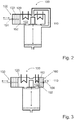
- Fig. 7 schematically shows a further embodiment of a heat exchanger assembly 100 according to the invention.
- the working medium passage 124 is opened, while the working medium passage 114 closed by the position of the rotary valve 220, at least obstructed flow preventing.
- Fig. 8 1 schematically shows a further embodiment of a heat exchanger arrangement 100 according to the invention, in which a circulation compressor 142 or another flow device is inserted into the circulation line 140, so that a separate flow device 142 is not necessary for each of the working medium passages 114, 124.
- the circulation compressor 142 With the aid of the circulation compressor 142, the exchange of the working medium 102 between one of the heat transfer chambers 110, 120 and the working space 210 can be accelerated, so that the cycle time of the cycle can be shortened.
- the heat exchanger assembly 100 is constructed particularly compact according to the illustrated embodiment. On a chamber bridge is omitted. Instead, the chambers 110, 120 are separated from each other only by a partition wall 127, wherein an opening in the partition wall 127 forms the connection of the chambers 110, 120 and in this area the circulation line 140 opens.
- Fig. 9 schematically shows a sectional view of another embodiment of a heat exchanger assembly 100 according to the invention, which is characterized by a particularly compact design and in which all elements necessary for effective circulation are housed inside.
- the chambers 110, 120 are separated by a channel partition 128 from each other, which at the same time takes over the task of the circulation line in addition to their separation effect.
- a wall channel 129 is provided inside the channel partition wall 128 through which the working medium 102 can flow from the working space 210 to at least one of the heat transfer chambers 110, 120 and back circulating, the countercurrent via at least one of the by means of the rotary valve 220 or other closing device controllable openings 114, 124 takes place.
- Fig. 9 provided flow device 142 is also integrated into the channel partition wall 128, so that the channel partition wall 128 in the preferred embodiment, the circulation compressor, an embodiment of the flow device 142, receives. This ensures an improved circulation between the chambers, as previously shown.
- the flow direction is indicated by arrows.
- Fig. 10 schematically shows a sectional view of another embodiment of a heat exchanger assembly 100 according to the invention, in which all necessary for effective circulation elements are also housed inside.
- the chambers 110, 120 are separated by a channel partition 128 from each other, which at the same time takes over the task of the circulation line in addition to their separation effect.
- 128 wall channels 129 are provided inside the channel partition, through which the working medium 102 from the working space 210 to at least one of the heat transfer chambers 110, 120 can flow, the countercurrent via at least one of the controllable by means of the rotary valve 220 or other closing device openings 114, 124 circulates back into the work space.
- the channel partition wall 128 has a regenerator 144, which acts as a heat exchanger and can absorb heat from the working medium 102 passing through or can deliver it to this.
- a regenerator 144 acts as a heat exchanger and can absorb heat from the working medium 102 passing through or can deliver it to this.
- This capability is enabled or improved by a heat-storing filling compound 146, which in a preferred embodiment of the regenerator 144 is contained therein. If the working medium 102 is to be cooled, the filling compound 146 absorbs heat, which can then be released again to the working medium 102 when it is to be heated. As a result, heating and cooling do not have to be carried out completely by the external heat and cooling sources, but external energy is saved and thus the efficiency of the energy converter is increased.
- the flow device 142 is also integrated into the channel partition wall 128 so that the channel partition 128 in the preferred embodiment receives the circulation compressor 142. This provides for improved circulation between the chambers, as previously shown.
- the regenerator 144 is without moving elements that conduct the flow of the working medium 102. Instead, two different flow paths for cooling and heating are provided, which are formed by the wall channels 129 and driven by the existing rotary valve 220. The processes cooling and warming are respectively in the Figures a) and b) of Fig. 11 shown, with arrows indicate the flow direction. As shown in Figure a), the warm working medium 102 is conducted from the working space 210 into the wall channel 129 and over the regenerator 144 where it gives off heat and flows cooled into the low temperature heat transfer chamber 110 for further cooling. According to Figure b), however, cool working medium 102 flows out of the working space 210 to the high-temperature heat transfer chamber 120.
- Fig. 11 shows schematically in sectional view five embodiments of a separating element 230 of a thermodynamic energy converter according to the invention.
- the ua in Fig. 1 In the working chamber 200 between the working medium 102 and the displacement fluid 202 shown, freely movable insulated separating element 230 preferably has a low mass at high strength.
- the separation conditions are improved with the same mass, in particular by a higher density to the inner wall of the working chamber 200th
- the shape A has the working space folded edges, which prevent in addition to higher tightness and tilting.
- the form B has the same advantages as the form A and also has a closed interior.
- the mold C has the same advantages as the mold A and is characterized by an improved security against tilting.
- the form D has a closed interior, also recorded by a line contact with the inner surface of the working chamber with good sealing effect a low tendency to jamming.
- the form E shows a thickening in the edge area. At least the shapes B and D, but also the shape E in the edge region, contain closed spaces for receiving a thermal insulation material, an insulation 232.
- separating element 230 itself may consist of an insulating material, so that the insulation 232 is integrally connected to the partition element 230 and forms the latter.
- Fig. 12 schematically shows a sectional view of another embodiment of a working chamber 200 of a heat exchanger assembly according to the invention.
- the thermal insulation between the working medium 102 and the displacement fluid 202 is ensured by an elastic separating element 231, which is preferably fixed in a fluid-tight manner at the inner edge region of the working chamber 200.
- the elastic separating element 231 expands more or less in the direction of the displacement fluid 202 (separating element 231 'in the deflected position, shown as a dashed line) and displaces it out of the working chamber. In the reverse process, the elastic separator 231 contracts again.
- the elastic separating element 231 can also ensure high tightness in addition to the thermal insulation, so that chemical interactions and evaporation of displacing fluid 202 into the working medium 102 are just as reliably avoided as a solution of working medium 102 in the displacing fluid 202.
- Fig. 13 schematically shows a sectional view of another embodiment of a working chamber 200 of a heat exchanger assembly according to the invention, a combination of the embodiment with elastic separating element 231 (see. Fig. 12 ) and the movable partition 230 (see FIG. Fig. 11 ) with insulation.
- an elastic membrane 233 at the inner edge region of the working chamber 200 is fixed fluid-tight and ensures a high density, so that chemical interactions and evaporation of Verdrängerfluid 202 in the working medium 102 is just as reliably avoided as a solution of working fluid 102 in the Verdrängerfluid 202.
- the insulation 232 is provided which has the separating element 230 connected to the membrane 233 and which does not have to extend to the wall of the working chamber 200. Therefore, the insulation 232 can move smoothly and with low friction in the working chamber 200.
- An alternative embodiment dispenses with the insulation 232, since the elastic membrane 233 is designed so that it acts insulating itself.
- FIGS. 14a and 14b show schematically in longitudinal section a further embodiment of the Gleichtikiolowait mattersers 20a, 20b for use in the energy converter according to the invention.
- the entire structure of the components of the Gleichtikiolowait mattersers 20a, 20b is substantially concentric, with a cladding tube 22 forms the outer boundary.
- the high-temperature heat transfer chamber 121 with the High-temperature heat exchanger 123 and the low-temperature heat transfer chamber 111 with the low-temperature heat exchanger 113 each executed in elongated configuration. This makes it possible to use a large heat exchanger surface with a small space requirement.
- the center of the Gleichdruckiolohunt mattersers 20 a, 20 b is occupied by the working chamber 201 with the working space 211 and the power transmission chamber 213.
- Working space 211 and power transmission chamber 213 are separated by the separation tube 234.
- the pressure of the working medium 102 is transferred to the displacement fluid 202, which can leave or enter the constant pressure multi-chamber container 20a, 20b via the main line 321.
- a rotary valve 220 is provided at both ends of the tubular working chamber 201 and a fan 142 is provided at one end of the working chamber 201.
- An arrow indicates the direction of flow.
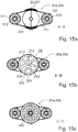
- FIGS. 15a to 15c show schematically in cross-sectional view a further embodiment of the tubular Gleichtikiolowait mattersers 20a, 20b, wherein the sectional planes AA, BB and CC in Fig. 14b are indicated.
- the cylindrical cladding tube 22 accommodates only the working chamber 201, while the high-temperature heat transfer chamber 121 with the high-temperature heat exchanger 123 and the low-temperature heat transfer chamber 111 with the low-temperature heat exchanger 113 are attached externally to the cladding tube 22.
- the rotary valve 220 is shown in section AA in the open position.
- the displacement fluid 202 enters the force transmission space 213, such as Fig. 15b in the section plane BB indicates a.
- the cross section also shows the separation tube 234 at low pressure of the working medium 102 or volume of the working space 211, while the maximum volume of the working space 211 and at the same time the minimum volume of the power transmission chamber 213 is indicated in dashed line of the separation tube 234 '.
- the cutting plane CC after Fig. 15c shows the fan 142.
- FIGS. 16a and 16b show the cutting planes AA and BB from the Fig. 14b however, show schematically in a cross-sectional view another embodiment of the tubular Gleichtikiolowait mattersers 20a, 20b in a completely cylindrical embodiment. Therefore, the cladding tube 22 encloses not only the working chamber 201, but also the high-temperature heat transfer chamber 121 with the high-temperature heat exchanger 123 and the low-temperature heat transfer chamber 111 with the low-temperature heat exchanger 113. There are provided a plurality of heat exchangers 113, 123 of smaller diameter, so that they in the narrow space between the working chamber 201 and cladding tube 22 fit and yet provide a sufficiently large heat transfer surface.
- the cut AA in Fig. 16a also shows the rotary valve 220 and concealed, shown by dashed lines, the fan 142 and the separation tube 234. In addition, the connection for the main line 321 can be seen.
- the cut BB, the Fig. 16b shows, can see the separation tube 234, in the interior of which the working space 211 is located with the working medium 102. Outside of the separation tube 234, the force transmission space 213 extends with the displacement fluid 202.
Description
Die Erfindung betrifft einen Gleichdruckmehrkammerbehälter für einen thermodynamischen Energiewandler, den thermodynamischen Energiewandler und ein Verfahren zum Betrieb des thermodynamischen Energiewandlers. Der Energiewandler dient zur Umwandlung thermischer Energie in mechanische Energie bzw. mechanischer Energie in thermische Energie. Ein gasförmiges Arbeitsmedium wird in einem thermodynamischen Kreisprozess durch Zufuhr höher temperierter Wärmeenergie von außen erhitzt und in zyklischer Folge durch Abfuhr mit niedriger temperierter Wärmeenergie von außen gekühlt. Die mechanische Energie wird durch Volumenarbeit erzeugt. Nach einem einmaligen Ablauf des Kreisprozesses ist der Ausgangszustand erreicht. Als Gleichdruckmehrkammerbehälter wird ein Volumenelement zum Einschließen eines Arbeitsmediums bezeichnet, das mehrere Kammern umfasst, zwischen denen sich der Druck des Arbeitsmediums stets ausgleicht.The invention relates to a constant pressure multi-chamber container for a thermodynamic energy converter, the thermodynamic energy converter and a method for operating the thermodynamic energy converter. The energy converter is used to convert thermal energy into mechanical energy or mechanical energy into thermal energy. A gaseous working medium is heated in a thermodynamic cycle by supplying heat-tempered heat energy from the outside and cooled in cyclic sequence by removal with low-tempered heat energy from the outside. The mechanical energy is generated by volume work. After a single run of the cycle process, the initial state is reached. As a constant pressure multi-chamber container, a volume element for enclosing a working medium is referred to, which comprises a plurality of chambers between which the pressure of the working medium always balances.
Entscheidend für einen Kreisprozess ist, dass das Arbeitsmittel nach einmaligem Durchlauf dieses Kreisprozesses denselben Zustand einnimmt, welches das Arbeitsmittel zu Beginn des Kreisprozesses hatte. Wird als Arbeitsmedium ein Gas verwendet, so ist dessen Zustand definiert durch die drei Zustandsgrößen p (Druck), V (Volumen) und T (Temperatur). Diese stehen unter Annahme eines idealen Gases im Zusammenhang: ![]()
![]()
Der Kreisprozess kann in einer Wärmekraftmaschine ablaufen, die mit Zylindern und Kolben ausgerüstet ist und die Volumenänderungsarbeit über sich bewegende mechanische Kolben, dem Pleuel und der Kurbelwelle, in Form einer Drehbewegung in mechanische Energie umgewandelt wird. Eine solche Wärmekraftmaschine beschreibt die Druckschrift
Derartige bekannte Systeme zur Umwandlung thermischer Energie in mechanische Energie bzw. mechanischer Energie in thermische Energie folgen jeweils für sich einem einzelnen, festgelegten Kreisprozess. Der Nachteil dessen ist, dass in den jeweiligen Anwendungsfeldern der Bewegungsspielraum der Konstruktion dahingehend eingeschränkt ist. Vor allem aber ergeben sich Einschränkungen durch die starren Bewegungsvorgaben des Kurbeltriebs.Such known systems for converting thermal energy into mechanical energy or mechanical energy into thermal energy each follow a single, fixed cyclic process. The disadvantage of this is that in the respective fields of application the range of motion of the construction is limited to this extent. Above all, however, there are limitations due to the rigid motion specifications of the crank mechanism.
Ein weiterer Energiewandler zur Umwandlung thermischer in mechanische Energie ist aus der Druckschrift
Die teilweise mit Hydrauliköl als Verdrängerfluid gefüllten beiden Druckbehälter sind über einen Rohrleitungsverbund mit Ventilen hydraulisch gekoppelt. Wenn sich durch Volumenarbeit des Arbeitsmediums in dem ersten Druckbehälter eine Deckelfläche des Verdrängerfluids in eine Richtung, z. B. nach unten, und das Verdrängerfluid von dem ersten zu dem zweiten Druckbehälter bewegt, bewegt sich die Deckelfläche des Verdrängerfluids des zweiten, zu dem ersten komplementären Druckbehälters in die Gegenrichtung. Im Rohrleitungsverbund ist zwischen den zwei Druckbehältern eine kraftumformende Einheit, z. B. ein Hydraulikmotor oder ein Linearantrieb, eingebunden, worüber mechanische Energie nutzbar ist. Durch die zwei miteinander hydraulisch verbundenen Druckbehälter erfolgt gleichzeitig der Ablauf zweier Kreisprozesse, jedoch mit taktverschobener Folge der Zustandsänderungen.The two pressure vessels, which are partially filled with hydraulic oil as the displacement fluid, are hydraulically coupled via a pipeline network with valves. If through Volume work of the working medium in the first pressure vessel, a cover surface of the displacement fluid in one direction, z. Down, and the displacer fluid moves from the first to the second pressure vessel, the lid surface of the displacer fluid of the second, to the first complementary pressure vessel moves in the opposite direction. In the pipeline network is between the two pressure vessels a kraftumformende unit, z. As a hydraulic motor or a linear drive, integrated, about which mechanical energy is available. At the same time, the two hydraulically connected pressure vessels cause two cycles to occur, but with a clock-shifted sequence of state changes.
Die geometrische Einengung des Prozessablaufes durch die Bewegungsvorgaben des Kurbeltriebs wird überwunden, da anstelle des mechanischen Kolbens im Zylinder die Kraftübertragung der Volumenarbeit über eine hydraulische Flüssigkeit erfolgt, die quasi inkompressibel ist, wie z. B. Hydrauliköl. Das Hydrauliköl übernimmt zugleich über eine Rohrleitung die Kraftübertragung, z. B. auf einen Hydraulikmotor, der die mechanische Energie in eine Drehbewegung überführt und damit nutzbar macht. Konstruktionsbedingt durch die Regelung mit Hilfe der Ventile und der Umdrehungszahl der im Stand der Technik vorgeschlagenen Rohrlüfter sind vielfältige polytrope Kompressionsverläufe und Entspannungsverläufe des Arbeitsmediums möglich. Dies kann allerdings nur in den Grenzen von deren Regelung und der Volumengrenze des Raumes im Druckbehälter erfolgen. Weitere Energiewandler sind aus den Druckschriften
Die Aufgabe wird insbesondere gelöst durch einen thermodynamischen Energiewandler, dessen Kernbaustein ein Volumenelement zum Einschließen eines Arbeitsmediums innerhalb eines in seiner Größe veränderlichen Volumens, nachfolgend als Gleichdruckmehrkammerbehälter bezeichnet, zur Aufnahme eines gasförmigen Arbeitsmediums darstellt. Der Gleichdruckmehrkammerbehälter weist eine das innere Volumen in Wärmeübertragerkammern sowie eine Arbeitskammer unterteilende Wandung auf, wobei innerhalb der Arbeitskammer ein die Arbeitskammer in einen mit dem Arbeitsmedium beaufschlagten Arbeitsraum und einen mit einem Verdrängerfluid beaufschlagten Kraftübertragungsraum unterteilendes Trennelement ausgebildet ist. Die Wärmeübertragerkammern und der Arbeitsraum sind untereinander fluidtechnisch derart miteinander verbunden ausgebildet, dass das Arbeitsmedium innerhalb des Volumenelements den gleichen Druck aufweist sowie jede Wärmeübertragerkammer über einen Einlass und einen getrennt vom Einlass ausgebildeten Auslass mit dem Arbeitsraum verbunden ist.The object is achieved in particular by a thermodynamic energy converter whose core component is a volume element for enclosing a working medium within a variable in its volume, hereinafter referred to as equal pressure multi-chamber container, for receiving a gaseous working medium. The Gleichdruckmehrkammerbehälter has a the inner volume in heat exchanger chambers and a working chamber dividing wall, wherein within the working chamber a working chamber in a working medium with the applied working space and a force acting on a Verdrängerfluid Kraftübertragungsraum separating element is trained. The heat transfer chambers and the working space are fluidly interconnected such that the working medium within the volume element has the same pressure and each heat transfer chamber is connected to the working space via an inlet and an outlet formed separately from the inlet.
Die Arbeitskammer bildet in dem mit dem Arbeitsmedium beaufschlagten Bereich einen Arbeitsraum, in welchem während des Betriebes der vorgesehene thermodynamische Kreisprozess abläuft. Die Arbeitskammer ist mit der Hochtemperaturwärmeübertragerkammer sowie mit der Niedertemperaturwärmeübertragerkammer zumindest über jeweils einen steuerbaren Arbeitsmediumdurchlass verbunden.The working chamber forms in the area acted upon by the working medium a working space in which runs during operation of the proposed thermodynamic cycle. The working chamber is connected to the high-temperature heat transfer chamber and to the low-temperature heat transfer chamber at least via in each case one controllable working medium passage.
Erfindungsgemäß ist jeweils ein Einlass oder ein Auslass als Verbindung zwischen den Wärmeübertragerkammern und dem Arbeitsraum mit mindestens einer Vorrichtung zum Beeinflussen der Durchströmung der Wärmeübertragerkammern mit Arbeitsmedium derart ausgebildet, dass eine Durchströmung mindestens einer der Wärmeübertragerkammern verhindert sowie eine Durchströmung mindestens einer anderen Wärmeübertragerkammer gefördert wird.According to the invention, in each case an inlet or an outlet as a connection between the heat exchanger chambers and the working space is designed with at least one device for influencing the flow through the heat exchanger chambers with working medium such that a flow through at least one of the heat exchanger chambers is prevented and a flow through at least one other heat exchanger chamber is conveyed.
Der Fluidstrom durch die Arbeitsmediumdurchlässe wird somit über die Vorrichtung zum Beeinflussen der Durchströmung der Wärmeübertragerkammern mit Arbeitsmedium, auch als Schließvorrichtung bezeichnet, gesteuert. Beide Wärmeübertragerkammern sind bei einer bevorzugten Ausgestaltung der Erfindung durch eine gemeinsame Zirkulationsleitung mit ihrem jeweiligen Arbeitsraum in der Weise verbunden, dass das Arbeitsmedium zwischen jeweils einer der Wärmeübertragerkammern mit geöffnetem Arbeitsmediumdurchlass und der Arbeitskammer zirkulieren kann. Auch getrennte Zirkulationsleitungen sind von der Erfindung umfasst, wären aber mit einem höheren apparativen Aufwand verbunden. Es sei denn, eine bestimmte Ausführungsform erfordert dies.The fluid flow through the working medium passages is thus controlled by the device for influencing the flow through the heat transfer chambers with working medium, also referred to as closing device. Both heat transfer chambers are connected in a preferred embodiment of the invention by a common circulation line with their respective working space in such a way that the working medium can circulate between each one of the heat transfer chambers with open working medium passage and the working chamber. Separate circulation lines are also included in the invention, but would involve a higher outlay on equipment. Unless a particular embodiment requires it.
Ein Beispiel für eine solche Ausführungsform ist eine rohrförmige Ausbildung der Arbeitskammer, bei der im Inneren des Rohrs ein schlauchartiges, flexibles Trennelement eingesetzt und an den Enden so mit dem Rohr verbunden ist, dass ein dichter Abschluss entsteht. Damit bildet sich zwischen dem Rohr und dem Trennelement der Kraftübertragungsraum aus, während innerhalb des schlauchförmigen Trennelements der Arbeitsraum ausgebildet ist.An example of such an embodiment is a tubular design of the working chamber, in which a hose-like, flexible separating element is inserted inside the tube and connected at the ends to the tube so that a tight seal is formed. This forms between the pipe and the Separating the power transmission chamber, while formed within the tubular separating element of the working space.
Außerhalb der rohrförmigen Arbeitskammer sind die Wärmeübertragerkammern angeordnet, beispielsweise als separate Kammern, die genügend Raum für die Aufnahme des Wärmeübertragers bieten und sich bevorzugt in Längsrichtung zur rohrförmigen Arbeitskammer erstrecken. Alternativ hierzu ist bei einer besonders platzsparenden Ausführung auch ein Hüllrohr zur Aufnahme der Wärmeübertrager vorgesehen. Dazu ist das Hüllrohr in zwei Halbschalen getrennt, so dass sich separate Kammern herausbilden. Im Interesse einer ausreichenden Leistung des Wärmeübertragers ist dieser bevorzugt als mehrere Wärmeübertrager kleineren Durchmessers ausgeführt, so dass diese in den engen Raum zwischen dem Hüllrohr und der rohrförmigen Arbeitskammer parallel zueinander verlaufend montiert werden können.Outside the tubular working chamber, the heat transfer chambers are arranged, for example, as separate chambers, which provide sufficient space for receiving the heat exchanger and preferably extend in the longitudinal direction of the tubular working chamber. Alternatively, a cladding tube for receiving the heat exchanger is provided in a particularly space-saving design. For this purpose, the cladding tube is separated into two half-shells, so that separate chambers are formed. In the interest of sufficient performance of the heat exchanger, this is preferably designed as a plurality of heat exchangers of smaller diameter, so that they can be mounted in the narrow space between the cladding tube and the tubular working chamber extending parallel to each other.
Zwischen dem Arbeitsraum und den Wärmeübertragerkammern besteht an den Stirnseiten eine Verbindung, die ein Durchströmen mit dem Arbeitsmedium ermöglicht. Dabei ist eine Schließvorrichtung vorgesehen, optional auch ein zusätzlicher Lüfter, um eine gezielte Steuerung der Durchströmung mit dem Arbeitsmedium zu ermöglichen.Between the working space and the heat exchanger chambers, there is a connection at the end faces, which allows a flow through the working medium. In this case, a closing device is provided, optionally also an additional fan in order to enable targeted control of the flow with the working medium.
Der thermodynamische Energiewandler ist mit zumindest einem ersten und einem zweiten Gleichdruckmehrkammerbehälter ausgestattet. Jeder der Gleichdruckmehrkammerbehälter ist in dem Bereich der Arbeitskammer, in dem das Verdrängerfluid anliegt und ein Kraftübertragungsraum gebildet wird, über wenigstens eine Hauptleitung für das Verdrängerfluid mit einer Fluidenergieumformeranordnung zur Umformung kinetischer Strömungsenergie des Verdrängerfluids (nachfolgend nur kurz Fluidenergie genannt) in mechanische Energie an unterschiedlichen Eingängen der Fluidenergieumformeranordnung verbunden. Bei einer Druckdifferenz zwischen dem ersten und dem zweiten Gleichdruckmehrkammerbehälter strömt das Verdrängerfluid von dem Kraftübertragungsraum mit dem höheren Druck zu dem Kraftübertragungsraum mit dem niedrigeren Druck über eine Fluidenergieumformeranordnung.The thermodynamic energy converter is equipped with at least a first and a second constant pressure multi-chamber container. Each of the constant pressure multichamber vessels is in the region of the working chamber in which the displacement fluid is applied and a force transmission space is formed via at least one main line for the displacement fluid with a fluid energy converter arrangement for converting kinetic energy flow of the positive displacement fluid (hereinafter referred to as fluid energy) into mechanical energy at different inputs connected to the Fluidenergieumformeranordnung. At a pressure differential between the first and second constant pressure multi-chamber tanks, the positive displacement fluid flows from the higher pressure power transmission space to the lower pressure power transmission space via a fluid energy converter arrangement.
Nach einer vorteilhaften Ausgestaltung der Erfindung ist zur Steuerung der Arbeitsmediumdurchlässe ein Drehschieber vorgesehen, der den Strömungsquerschnitt der Arbeitsmediumdurchlässe zumindest so stark vermindert, dass die Strömung behindert wird.According to an advantageous embodiment of the invention, a rotary valve is provided for controlling the Arbeitsmediumdurchlässe, the Flow cross-section of the working medium passages at least reduced so much that the flow is obstructed.
Ziel des thermodynamischen Energiewandlers ist es, bereitstehende Wärmeenergie in kinetische Energie bzw. im umgekehrten Prozess kinetische Energie in thermische Energie (Wärme oder Kälte) umzuwandeln. Zur Umwandlung in kinetische Energie wird die Wärmeenergie genutzt, um ein Arbeitsmedium zu erwärmen. Diese Erwärmung führt bei einem als ideales Gas angenommenen Arbeitsmedium zu einer Erhöhung des Druckes und/oder des eingenommenen Volumens des Arbeitsmediums unter der Voraussetzung, dass die Masse des Arbeitsmediums konstant bleibt. Eine Volumenänderung führt dann zu einer Teilchenbewegung und somit zur Umwandlung in Bewegungsenergie.The aim of the thermodynamic energy converter is to convert the available heat energy into kinetic energy or in the reverse process kinetic energy into thermal energy (heat or cold). For conversion to kinetic energy, the heat energy is used to heat a working medium. In the case of a working medium assumed to be ideal, this heating leads to an increase in the pressure and / or the occupied volume of the working medium, provided that the mass of the working medium remains constant. A volume change then leads to a particle movement and thus to the conversion into kinetic energy.
Der erfindungsgemäße thermodynamische Energiewandler ist aus mindestens zwei Gleichdruckmehrkammerbehältern ausgebildet, welche im Bereich eines Kraftübertragungsraums über wenigstens eine Hauptleitung hydraulisch miteinander verbunden sind. In der Hauptleitung, die ein Verdrängerfluid führt, ist eine Fluidenergieumformeranordnung, umfassend einen Fluidenergieumformer und eine Ventilanordnung, vorgesehen. Mit der Hauptleitung können auch drei, vier oder mehr Gleichdruckmehrkammerbehälter verbunden werden, so dass bei einem Druckgefälle des Verdrängerfluids eine Strömung über den Fluidenergieumformer erfolgt und die Strömungsenergie in wenigstens eine andere Energieform umwandelbar ist.The thermodynamic energy converter according to the invention is formed from at least two constant pressure multi-chamber containers, which are hydraulically connected to each other in the region of a power transmission chamber via at least one main line. In the main conduit carrying a positive displacement fluid, there is provided a fluid energy converter assembly comprising a fluid energy converter and a valve assembly. Three, four or more constant-pressure multicontainer containers can also be connected to the main line, so that, in the case of a pressure gradient of the displacing fluid, a flow takes place via the fluid energy converter and the flow energy can be converted into at least one other form of energy.
Ein solcher Gleichdruckmehrkammerbehälter dient auch als ein Temperierbehälter zum Temperieren eines Arbeitsmediums. Er ist als ein Gleichdruckmehrkammerbehälter mit mindestens drei zueinander offenen Kammern aufgebaut, sodass eine Temperatur- oder Volumenänderung des Arbeitsmediums in einer Kammer immer einen Massentransport zwischen den Kammern bewirkt, die Druckdifferenz nach dem Massentransport zwischen den Kammern aber stets null ist.Such a constant pressure multi-chamber container also serves as a tempering for tempering a working medium. It is constructed as a constant pressure multi-chamber container with at least three mutually open chambers, so that a temperature or volume change of the working medium in a chamber always causes mass transport between the chambers, but the pressure difference after the mass transport between the chambers is always zero.
In mindestens einer der Kammern des Behälters, die als Hochtemperaturwärmeübertragerkammer ausgeführt ist, ist ein Hochtemperaturwärmeübertrager angeordnet, in mindestens einer zweiten Kammer ist ein Niedertemperaturwärmeübertrager platziert, so dass eine Niedertemperaturwärmeübertragerkammer gebildet wird. Mindestens eine dritte Kammer ist zumindest teilweise mit einem Verdrängerfluid gefüllt. Diese dritte Kammer ist als eine Arbeitskammer ausgebildet. Der darin ebenfalls vorgesehene, mit Arbeitsmedium gefüllte Bereich wird als Arbeitsraum definiert. Der in der Arbeitskammer mit Verdrängerfluid gefüllte Bereich wird als Kraftübertragungsraum definiert.In at least one of the chambers of the container, which is designed as a high-temperature heat transfer chamber, a high-temperature heat exchanger is arranged in at least one second chamber, a low-temperature heat exchanger is placed, so that a low-temperature heat transfer chamber is formed. At least one third chamber is at least partially filled with a positive displacement fluid. This third chamber is designed as a working chamber. The also provided there, filled with working fluid area is defined as a working space. The filled in the working chamber with positive displacement fluid is defined as a power transmission chamber.
In den meisten Betriebsfällen ist die dritte Kammer, die Arbeitskammer, nur teilweise mit dem Verdrängerfluid gefüllt. Prinzipiell ist es auch möglich, dass der obere Totpunkt bei einem Arbeitsraumvolumen VAR=0 erreicht wird, dann wirkt bei der Expansion nur das Volumen der Wärmeübertragerkammern. Der thermische und damit der mechanische Wirkungsgrad sind dabei deutlich geringer als bei VAR > 0.In most operating cases, the third chamber, the working chamber, is only partially filled with the displacer fluid. In principle, it is also possible that the top dead center is reached at a working space volume V AR = 0, then acts in the expansion, only the volume of the heat transfer chambers. The thermal and thus the mechanical efficiency are significantly lower than at V AR > 0.
Jede der Kammern, die als Hochtemperaturwärmeübertragerkammer oder als Niedertemperaturwärmeübertragerkammer ausgeführt ist, hat zwei Öffnungen, auch als Arbeitsmediumdurchlass bezeichnet, zu der Kammer, von der ein Teil als Arbeitsraum definiert ist, aber nur eine davon, entweder die Hochtemperaturwärmeübertragerkammer oder die Niedertemperaturwärmeübertragerkammer, wird durch eine Schließvorrichtung bei Bedarf gesperrt oder der Strömungswiderstand erhöht. Dieser Vorgang wird auch als Abschatten bezeichnet, wobei die Schließvorrichtung die Öffnung nicht druckdicht schließen muss, damit Temperaturunterschiede in den Kammern gehalten werden können. Die Verbindung zwischen den Wärmeübertragerkammern und der Arbeitskammer ist demnach mit einer Schließvorrichtung versehen, die es ermöglicht, die Durchströmung mindestens einer der Wärmeübertragerkammern derart durch Vergrößerung des Strömungswiderstandes zu behindern, dass das Arbeitsmedium bevorzugt durch die andere Wärmeübertragerkammer strömt. Das kann durch eine Schließvorrichtung, die als Blende, Drehschieber oder eine andere Drosselvorrichtung ausgeführt ist, erfolgen. Somit sind die Kammern zueinander immer offen, aber ein Durchströmen der Kammern erfolgt nur dann, wenn beide Öffnungen offen bzw. nicht abgeschattet sind.Each of the chambers, which is embodied as a high-temperature heat transfer chamber or as a low-temperature heat transfer chamber, has two openings, also referred to as Arbeitsmediumdurchlass, to the chamber, a part of which is defined as a working space, but only one of them, either the high-temperature heat transfer chamber or the low-temperature heat transfer chamber, by a Locking device locked if necessary or the flow resistance increased. This process is also referred to as shadowing, wherein the closing device does not have to close the opening pressure-tight, so that temperature differences can be kept in the chambers. The connection between the heat transfer chambers and the working chamber is therefore provided with a closing device which makes it possible to hinder the flow through at least one of the heat transfer chambers by increasing the flow resistance, that the working medium preferably flows through the other heat transfer chamber. This can be done by a closing device, which is designed as a diaphragm, rotary valve or other throttle device. Thus, the chambers are always open to each other, but a flow through the chambers takes place only if both openings are open or not shaded.
In einem speziellen Betriebsfall kann auch die Durchströmung beider Wärmeübertragerkammern derart durch Vergrößerung des Strömungswiderstandes in der oder den Öffnungen behindert sein, dass eine Expansion oder eine Kompression des gasförmigen Arbeitsmediums adiabat und nicht isotherm erfolgt. In dem Fall kann das Arbeitsmedium über eine Zirkulationsleitung in die oder aus den Wärmeübertragerkammern gefördert werden, ohne dass das Gas durch die Hochtemperaturwärmeübertragerkammer oder die Niedertemperaturwärmeübertragerkammer zirkuliert.In a special case of operation, the flow through both heat exchanger chambers may be hindered by increasing the flow resistance in the orifices such that an expansion or a compression of the gaseous working medium takes place adiabatically and not isothermally. In that case, the working medium can be conveyed via a circulation line into or out of the heat transfer chambers, without the gas passing through the High-temperature heat transfer chamber or the low-temperature heat transfer chamber circulates.
Im häufigsten Betriebsfall wird dem Arbeitsmedium in der Hochtemperaturwärmeübertragerkammer ständig Wärme zugeführt und vom Arbeitsmedium in der Niedertemperaturwärmeübertragerkammer ständig Wärme abgeführt. Das Arbeitsmedium in der Hochtemperaturwärmeübertragerkammer wird somit ständig erwärmt bzw. ist die Temperatur des Arbeitsmediums konstant hoch und das Arbeitsmedium in der Niedertemperaturwärmeübertragerkammer wird stets gekühlt bzw. ist die Temperatur des Arbeitsmediums konstant niedrig. Das Arbeitsmedium im Arbeitsraum weist im stationären Zustand eine mittlere Temperatur entsprechend dem Verhältnis von Kühl- und Heizleistung in den beiden anderen Kammern auf.In the most frequent case of operation, heat is constantly supplied to the working medium in the high-temperature heat transfer chamber and heat is constantly dissipated by the working medium in the low-temperature heat transfer chamber. The working medium in the high-temperature heat transfer chamber is thus constantly heated or the temperature of the working medium is constantly high and the working medium in the low-temperature heat transfer chamber is always cooled or the temperature of the working medium is constantly low. The working fluid in the working space, in the steady state, an average temperature corresponding to the ratio of cooling and heating power in the other two chambers.
Die gezielte Durchströmung einer der Wärmeübertragerkammern und der dazu offenen ersten Arbeitskammer bei gleichzeitiger Behinderung der Durchströmung der zweiten Wärmeübertragerkammer führt dazu, dass das Arbeitsmedium im Arbeitsraum auf Grund des deutlich höheren Wärmeübergangs bei erzwungener Konvektion die Temperatur der durchströmten Wärmeübertragerkammer annimmt. Der Druck im gesamten Gleichdruckmehrkammerbehälter sinkt bei gleichbleibendem Volumen bei Abkühlung oder steigt bei Erwärmung. Die gezielte Durchströmung wird erreicht, indem ein Strömungspfad gezielt eingestellt wird, beispielsweise durch Sperren oder Öffnen der Zugänge, der Öffnungen oder Arbeitsmediumdurchlässe zum Arbeitsraum. Weiterhin kann eine in den Strömungspfad eingefügte Strömungseinrichtung, z. B. ein Lüfter oder ein Zirkulationsverdichter, dafür sorgen, dass die Durchströmung mit erhöhtem Volumenstrom des Arbeitsmediums aktiv forciert erfolgt. Das erfindungsgemäße Verfahren läuft auch ohne eine Strömungseinrichtung ab, dann jedoch bei sehr geringem Wirkungsgrad, da nur durch das einströmende heiße Gas mit geringer Dichte eine Zirkulation in begrenztem Umfang hervorgerufen wird.The targeted flow through one of the heat transfer chambers and the open to the first working chamber while obstructing the flow through the second heat transfer chamber causes the working fluid in the working chamber due to the much higher heat transfer in forced convection, the temperature of the flowed through heat transfer chamber assumes. The pressure in the entire Gleichdruckmehrkammerbehälter decreases with constant volume when cooled or increases when heated. The targeted flow is achieved by a flow path is set specifically, for example, by blocking or opening the access, the openings or Arbeitsmediumdurchlässe to the working space. Furthermore, an inserted into the flow path flow device, for. As a fan or a circulation compressor, ensure that the flow is actively forced with increased flow of the working medium. The inventive method runs without a flow device, but then with very low efficiency, since only by the incoming hot gas with low density circulation is caused to a limited extent.
Bei einer beispielhaften Ausgangssituation liegt in allen drei Kammern (Hochtemperaturwärmeübertragerkammer, Niedertemperaturwärmeübertragerkammer, Arbeitsraum) eines Gleichdruckmehrkammerbehälters kaltes Gas als Arbeitsmedium vor. Bei Aktivierung der erfindungsgemäßen Vorrichtung wird das Gas in der Hochtemperaturwärmeübertragerkammer erwärmt. Da sie offen zu den anderen Kammern ist, strömt ein Teil des warmen Gases über die Öffnungen in die Niedertemperaturwärmeübertragerkammer und den Arbeitsraum. In der Niedertemperaturwärmeübertragerkammer wird das Gas sofort wieder abgekühlt und im Arbeitsraum ergibt sich eine Mischtemperatur. Bei Durchströmung von Arbeitsraum und Hochtemperaturwärmeübertragerkammer wird das darin enthaltene Gas erwärmt. Dabei strömt das Gas auch in die Niedertemperaturwärmeübertragerkammer, da immer ein Druckausgleich erfolgt. Aus der Niedertemperaturwärmeübertragerkammer tritt aber kein Gas aus, da keine Durchströmung erfolgen kann.In an exemplary starting situation, cold gas is present as the working medium in all three chambers (high-temperature heat transfer chamber, low-temperature heat transfer chamber, working chamber) of a constant pressure multichamber container. Upon activation of the device according to the invention, the gas is heated in the high-temperature heat transfer chamber. Since it is open to the other chambers, a portion of the warm gas flows over the openings into the low-temperature heat transfer chamber and the working space. In the Low-temperature heat transfer chamber, the gas is immediately cooled again and in the working space results in a mixing temperature. When flowing through the working space and high-temperature heat transfer chamber, the gas contained therein is heated. The gas also flows into the low-temperature heat transfer chamber, since there is always a pressure equalization. From the low-temperature heat transfer chamber but no gas exits, since no flow can take place.
Eine bevorzugte Ausgestaltung des Gleichdruckmehrkammerbehälters sieht im Bereich wenigstens eines der Arbeitsmediumdurchlässe und/oder der Zirkulationsleitung die Strömungseinrichtung zur Erhöhung einer Strömungsgeschwindigkeit des Arbeitsmediums zwischen der Arbeitskammer und wenigsten der einer der Kammern des Gleichdruckmehrkammerbehälters vor. Im Strömungspfad gibt es durch die Strömungseinrichtung, z. B. den Zirkulationsverdichter oder Lüfter, ein Druckgefälle, jedoch stellt sich zu jedem Zeitpunkt in allen Kammern gleicher Druck ein.A preferred embodiment of the constant pressure multichamber container provides in the region of at least one of the working medium passages and / or the circulation line the flow device for increasing a flow velocity of the working medium between the working chamber and at least one of the chambers of the constant pressure multichamber container. In the flow path, there are by the flow device, for. As the circulation compressor or fan, a pressure drop, but arises at any time in all chambers equal pressure.
Damit das Arbeitsmedium die Wärmeübertragerkammern aktiv durchströmen kann, fördert idealerweise die Strömungseinrichtung das Arbeitsmedium vom Arbeitsraum zu den Wärmeübertragerkammern, durch die Wärmeübertragerkammern hindurch und wieder in den Arbeitsraum hinein. Zur Anpassung der Konvektion und des Massedurchsatzes des Arbeitsmediums ist bei einer bevorzugten Ausführungsform des erfindungsgemäßen Gleichdruckmehrkammerbehälters der Volumenstrom der Strömungseinrichtung gesteuert, beispielsweise durch einen drehzahlgesteuerten Lüfter.
Damit das Arbeitsmedium, welches sich im Arbeitsraum befindet, schnell abgekühlt oder erhitzt werden kann, muss der Wärmetransport vom Arbeitsmedium in die Wand des Gleichdruckmehrkammerbehälters oder umgekehrt minimiert werden. Hierzu verfügt zumindest die Arbeitskammer, vorzugsweise der gesamte Gleichdruckmehrkammerbehälter, über eine Isolierung, insbesondere eine Innenisolierung, mit sehr geringer Wärmeleitfähigkeit.So that the working medium can actively flow through the heat transfer chambers, the flow device ideally conveys the working medium from the working space to the heat transfer chambers, through the heat transfer chambers and back into the working space. To adapt the convection and the mass flow rate of the working medium, the volume flow of the flow device is controlled in a preferred embodiment of the invention Gleichdruckmehrkammerbehälters, for example by a speed-controlled fan.
So that the working medium, which is located in the working space, can be cooled or heated quickly, the heat transfer from the working medium into the wall of the constant pressure multi-chamber container or vice versa must be minimized. For this purpose, at least the working chamber, preferably the entire constant pressure multi-chamber container, has an insulation, in particular an inner insulation, with very low thermal conductivity.
Zudem ist auf der Oberfläche des Verdrängerfluids bevorzugt ein Trennelement angeordnet, welches bei fallendem oder steigendem Pegel des Verdrängerfluids ebenfalls sinkt oder steigt. Das Trennelement kann isoliert sein oder selbst aus einem isolierenden Material bestehen oder eine Membran, umfassen, die isolierend beschichtet ist oder selbst aus einem isolierenden Material besteht. Das Trennelement dient somit als zumindest thermische Trennung zwischen dem Verdrängerfluid und dem Arbeitsmedium und kann in der bevorzugten Ausgestaltung neben einem verminderten Wärmeübergang auch etwa auftretende Wechselwirkungen zwischen beiden verhindern, wie z. B. das Verdampfen von Verdrängerfluid in das Arbeitsmedium oder die Lösung von Teilen des Arbeitsmediums im Verdrängerfluid. Eine besondere Ausführungsform stellt ein bewegliches Trennelement dar. Das bewegliche Trennelement ist so gestaltet, dass sein Auftrieb durch Materialauswahl und/oder Form des Trennelements gegenüber dem Verdrängerfluid größer ist als seine Gewichtskraft. Dadurch bleibt es immer auf der Oberfläche des Verdrängerfluids.In addition, a separating element is preferably arranged on the surface of the displacement fluid, which also decreases or increases with decreasing or increasing level of the displacement fluid. The separating element may be insulated or may itself consist of an insulating material or comprise a membrane which is coated in an insulating manner or itself consists of an insulating material. The separating element thus serves as at least thermal separation between the displacement fluid and the working medium and can prevent in the preferred embodiment in addition to a reduced heat transfer and any interactions between them, such. B. the evaporation of Verdrängerfluid in the working fluid or the solution of parts of the working fluid in the displacement fluid. A particular embodiment is a movable separating element. The movable separating element is designed so that its buoyancy by material selection and / or shape of the separating element relative to the displacement fluid is greater than its weight. As a result, it always remains on the surface of the displacement fluid.
In einer besonders vorteilhaften Ausgestaltung des Trennelements weist dieses eine thermische Isolierung auf oder besteht selbst aus einem isolierenden Material und verhindert nachteiligen Wärmeübergang zwischen dem Arbeitsmedium und dem Verdrängerfluid.In a particularly advantageous embodiment of the separating element, this has a thermal insulation or itself consists of an insulating material and prevents adverse heat transfer between the working fluid and the displacement fluid.
Weitere Ausführungsformen der Isolierung zwischen Arbeitsmedium und Verdrängerfluid sind ein elastisches Trennelement, das am Arbeitsraum innen befestigt ist, oder eine Membran, umfassend ein bewegliches Trennelement. Das elastische Trennelement und die Membran bilden zugleich eine stoffdichte Barriere zwischen dem Verdrängerfluid und dem Arbeitsmedium aus.Further embodiments of the insulation between the working medium and the displacement fluid are an elastic separating element which is fastened to the working space on the inside, or a membrane comprising a movable separating element. The elastic separating element and the membrane simultaneously form a material-tight barrier between the displacement fluid and the working medium.
Durch die Isolation wird die Effizienz des erfindungsgemäßen thermodynamischen Energiewandlers weiter verbessert. In vorteilhaften Ausführungsformen ist das Trennelement als eine Scheibe mit von dem Verdrängerfluid weg rechtwinklig oder konisch nach oben gezogenem Rand, als eine Hohlstruktur oder als ein abgeplattetes Rotationsellipsoid ausgeführt. Das Trennelement kann zusätzlich ein Dichtelement aufweisen, um den Spalt zur Innenisolierung des Behälters zu schließen. Wenn das Trennelement eine umlaufende Dichtung zur Innenwand des Kraftübertragungsraums aufweist, sodass das Arbeitsmedium nicht in direktem Kontakt zum Verdrängerfluid steht, dann wäre die Funktion ähnlich der eines Kolbenspeichers. Das Trennelement entspricht dann dem Kolben, die Arbeitskammer, in dem das Trennelement zumindest längsbeweglich angeordnet ist, dem Zylinder.The insulation further improves the efficiency of the thermodynamic energy converter according to the invention. In advantageous embodiments, the separating element is designed as a disk with a perpendicular or conically upwardly drawn edge away from the displacing fluid, as a hollow structure or as a flattened ellipsoid of revolution. The separator may additionally include a sealing member to close the gap for internal insulation of the container. If the separator has a circumferential seal to the inner wall of the transmission chamber so that the working fluid is not in direct contact with the displacer fluid, then the function would be similar to that of a piston accumulator. The separating element then corresponds to the piston, the working chamber in which the separating element is arranged at least longitudinally movable, the cylinder.
Die Innenisolation der Arbeitskammer und die Isolation zum Verdrängerfluid kann auch in einem Teil durch eine Membran, auch als Blase bezeichnet, erzielt werden, vor allem wenn deren Wand eine sehr geringe Wärmeleitfähigkeit aufweist. Diese Ausführungsform hat den Vorteil, dass die Membran zusätzlich den Arbeitsraum vom Verdrängerfluid hermetisch abtrennt und Dichtheitsprobleme vermeidet. Damit wird ein Lösen und Entgasen des Arbeitsmediums in das Verdrängerfluid bzw. aus dem Verdrängerfluid vor allem bei Druckänderung noch besser verhindert, als es durch das Trennelement möglich ist.The inner insulation of the working chamber and the insulation to the displacement fluid can also be achieved in a part by a membrane, also referred to as a bubble, especially if the wall has a very low thermal conductivity. These Embodiment has the advantage that the membrane also hermetically separates the working space from the displacement and avoids leakage problems. In order for a loosening and degassing of the working medium in the positive displacement fluid or from the positive displacement fluid is better prevented, especially in pressure change, as it is possible through the separator.
Um die Temperaturen in den Wärmeübertragerkammern bzw. den in den einzelnen Prozessschritten notwendigen Wärmestrom, der zwischen einer externen Wärmequelle oder Kältequelle über die Wärmeübertrager mit dem Arbeitsmedium im erfindungsgemäßen thermodynamischen Energiewandler übertragen wird, besser steuern zu können, kann wenigstens eine der Wärmeübertragerkammern steuerbar ausgeführt sein. Hierzu ist es beispielsweise vorgesehen, dass mehrere, einzeln steuerbare Wärmeübertrager in einer Wärmeübertragerkammer angeordnet sind oder mehrere einzelne Kammern jeweils mit Hochtemperatur- bzw. Niedertemperaturwärmeübertragern ausgebildet sind. Die Verbindung dieser Kammern untereinander kann wiederum drosselbar, beispielsweise durch Klappen, Blenden oder Schieber, sein. Je nach Betriebsweise des Systems sind für Erhitzen, Halten einer Temperatur und nichtisotherme Expansion oder Kompression unterschiedliche Wärmemengen notwendig. Durch eine Drosselung im Sinne der vorliegenden Erfindung kann Wärme außerhalb oder innerhalb des Kammersystems zwischengespeichert werden.In order to be able to better control the temperatures in the heat exchanger chambers or the heat flow required in the individual process steps, which is transmitted between the heat exchanger and the working medium in the thermodynamic energy converter according to the invention, at least one of the heat exchanger chambers can be designed to be controllable. For this purpose, it is provided, for example, that a plurality of individually controllable heat exchangers are arranged in a heat transfer chamber or a plurality of individual chambers are each formed with high-temperature or low-temperature heat exchangers. The connection of these chambers with each other in turn can be throttled, for example by flaps, panels or slides. Depending on the operating mode of the system, different amounts of heat are required for heating, maintaining a temperature and non-isothermal expansion or compression. By throttling in the context of the present invention, heat outside or inside the chamber system can be cached.
Außerdem ist es möglich, über verstellbare Wände, Stellkolben oder durch ein veränderliches Niveau einer Flüssigkeit, welche den unteren Teil einer Wärmeübertragerkammer füllt, das effektiv nutzbare Volumen in einer Wärmeübertragerkammer so zu verändern, dass stets das optimale Leistungsverhältnis von Hochtemperaturwärmeübertragerkammer und Niedertemperaturwärmeübertragerkammer vorliegt. Die verstellbaren Volumina der Wärmeübertragerkammern dienen dem effizienten Betrieb des Systems, denn umso kleiner das Volumen der Wärmeübertragerkammern im Verhältnis zum Volumen des Arbeitsraums ist, umso größer ist die nutzbare Leistung. Je nach Wärme- oder Kältebedarf sind deshalb unterschiedliche Volumina der Wärmeübertragerkammern notwendig. Damit weist bei dem erfindungsgemäßen Gleichdruckmehrkammerbehälter wenigstens eine der Wärmeübertragerkammern einen einstellbaren Arbeitspunkt auf, indem das Volumen der Wärmeübertragerkammer einstellbar ist. Dies kann durch eine Stellkolbenanordnung, umfassend ein Zylinderelement und einen Stellkolben, durch mittels Steuerklappen zuschaltbare Steuerkammern oder durch eine Flüssigkeitssteuerung, wobei eine Steuerflüssigkeit Teile des Volumens der Wärmeübertragerkammer einnimmt, eingestellt werden.In addition, it is possible, via adjustable walls, actuating pistons or by a variable level of a liquid filling the lower part of a heat transfer chamber, to change the effective volume in a heat transfer chamber so that there is always the optimum power ratio of the high temperature heat transfer chamber and the low temperature heat transfer chamber. The adjustable volumes of the heat transfer chambers serve to operate the system efficiently, because the smaller the volume of the heat transfer chambers in relation to the volume of the work space, the greater the usable power. Depending on the heat or cooling requirements, therefore, different volumes of the heat transfer chambers are necessary. In the case of the constant-pressure multi-chamber container according to the invention, at least one of the heat exchanger chambers thus has an adjustable operating point in that the volume of the heat exchanger chamber can be adjusted. This can be achieved by an actuating piston arrangement comprising a cylinder element and an actuating piston by means of control flaps switchable control chambers or by a liquid control, wherein a control fluid occupies parts of the volume of the heat exchanger chamber can be adjusted.
Zwei dieser als Gleichdruckmehrkammerbehälter ausgeführten Temperierbehälter sind miteinander über die Fluidenergieumformeranordnung durch eine Hauptleitung in Form einer Rohr- oder Schlauchverbindung oder einer Verbindungsbohrung verbunden. In diese Verbindung ist mindestens ein Fluidenergieumformer integriert. Dies kann zum Beispiel ein rotatorisch wirkender Fluidmotor, aber auch ein Linearmotor oder ein sonstiger beweglicher Aktor sein.Two of these tempering containers designed as constant-pressure multi-chamber containers are connected to one another via the fluid-energy converter arrangement by a main line in the form of a pipe or hose connection or a connecting bore. At least one fluid energy converter is integrated in this connection. This can be, for example, a rotary-acting fluid motor, but also a linear motor or another movable actuator.
Damit die Durchströmung des Fluidenergieumformers geregelt werden kann, ist in die Hauptleitung ebenfalls eine Ventilanordnung integriert. Die Fluidenergieumformeranordnung ist dann in der Weise ausgebildet, dass die Hauptleitung für das Verdrängerfluid mit dem Fluidenergieumformer über eine Ventilanordnung verbunden ist, sodass die Strömungsrichtung in dem Fluidenergieumformer unabhängig von der Strömungsrichtung zwischen der Arbeitskammer einstellbar ist und/oder die Durchflussmenge des Verdrängerfluids in Abhängigkeit des Drucks und/oder der Temperatur des Arbeitsmediums im Druckbehälter gesteuert wird. Dadurch wird unabhängig von der Betriebsphase des Gleichdruckbehälters beispielsweise immer dieselbe Drehrichtung eines rotierenden Energiewandlers ermöglicht.So that the flow of the fluid energy converter can be regulated, a valve arrangement is also integrated in the main line. The fluid energy converter assembly is then configured such that the main line for the positive displacement fluid is connected to the fluidic energy converter via a valve arrangement such that the flow direction in the fluidic energy converter is adjustable independently of the flow direction between the working chamber and / or the flow rate of the positive displacement fluid as a function of the pressure and / or the temperature of the working medium is controlled in the pressure vessel. As a result, for example, always the same direction of rotation of a rotating energy converter is possible regardless of the operating phase of the constant pressure tank.
Parallel zu dieser Verbindung über die Hauptleitung können die zwei oder mehr Gleichdruckmehrkammerbehälter zusätzlich durch eine Bypassleitung mit Ventil verbunden sein, um einen schnellen Transport des Verdrängerfluids von dem Kraftübertragungsraum eines der Gleichdruckmehrkammerbehälter in den Kraftübertragungsraum eines anderen der Gleichdruckmehrkammerbehälter zu ermöglichen. Denn bei geringen Druckunterschieden zwischen den Kraftübertragungsräumen ist die über die Hauptleitung übertragbare Leistung nur noch sehr gering, so dass es insgesamt effizienter ist, den Vorgang des Druckausgleichs über die Bypassleitung zu beschleunigen, um den nächsten Prozessschritt eher einleiten zu können. Dazu ist bei dem Energiewandler zwischen der ersten und der zweiten Arbeitskammer eine Bypassleitung mit steuerbarem Durchfluss des Verdrängerfluids vorgesehen, wobei die Bypassleitung an jeder der mit Verdrängerfluid beaufschlagten Arbeitskammern jeweils im Bereich des Kraftübertragungsraums angeschlossen ist.In parallel with this connection via the main line, the two or more constant pressure multicontainer can be additionally connected by a bypass line with valve to allow rapid transport of the displacement of the force transmission space of one of the Gleichdruckmehrkammerbehälter in the power transmission chamber of another of the Gleichdruckmehrkammerbehälter. Because at low pressure differences between the power transmission chambers, the transferable via the main power is only very low, so that it is more efficient overall, to accelerate the process of pressure equalization via the bypass line in order to initiate the next process step sooner. For this purpose, in the energy converter between the first and the second working chamber, a bypass line with controllable flow of the positive displacement fluid is provided, wherein the bypass line at each of the positive displacement fluid acted upon working chambers each connected in the region of the power transmission chamber.
Besondere Vorteile bringt ein Gleichdruckmehrkammerbehälter, bei dem in einem Wandkanal ein Regenerator vorgesehen ist, der eine wärmespeichernde Füllmasse umfasst und der in einer ersten Durchströmungsrichtung Wärme aufnehmen und in einer zweiten Durchströmungsrichtung Wärme abgeben kann. Die Durchströmungsrichtung ist mittels der Schließvorrichtung, beispielsweise ausgeführt als Drehschieber, und wenigstens zwei getrennter Bereiche des Wandkanals steuerbar. Die optionale Ergänzung des Gleichdruckmehrkammerbehälters um den Regenerator verbessert den Gesamtwirkungsgrad weiter. Der Regenerator ist ein Wärmeübertrager mit der als Kurzzeit-Wärmespeicher dienenden Füllmasse, auch als Speichermasse bezeichnet, die abwechselnd von dem warmen und dem kalten Arbeitsmedium durchströmt wird. Wärme wird zuerst vom Arbeitsmedium auf den Wärmespeicher übertragen, um anschließend im Folgetakt wieder an das nachfolgend durchströmende Arbeitsmedium abgegeben zu werden. Wenn beispielsweise bei Erwärmung auch Arbeitsmedium in die Niedertemperaturwärmeübertragerkammer strömt, kann die Wärme zuvor an die Speichermasse des Regenerators abgegeben und in dieser gespeichert werden. Das Arbeistmedium muss also nicht vollständig in der Niedertemperaturwärmeübertragerkammer abgekühlt werden, sondern tritt bereits vorgekühlt dort ein. Wenn Arbeitsmedium aus der Niedertemperaturwärmeübertragerkammer austritt, kann die im Regenerator gespeicherte Wärme an das Arbeitsmedium übertragen werden, sodass ein Teil der erforderlichen Wärme zur Erwärmung des Arbeitsmediums nicht durch die externe Wärmezufuhr bereitgestellt werden muss.Particular advantages are brought about by a constant-pressure multi-chamber container in which a regenerator is provided in a wall channel, which comprises a heat-storing filling compound and can absorb heat in a first direction of flow and release heat in a second direction of flow. The flow direction is controllable by means of the closing device, for example designed as a rotary valve, and at least two separate regions of the wall channel. The optional addition of the equal pressure multi-chamber container around the regenerator further improves the overall efficiency. The regenerator is a heat exchanger with serving as a short-term heat storage filling material, also referred to as storage mass, which is alternately flowed through by the hot and the cold working fluid. Heat is first transferred from the working medium to the heat storage, in order subsequently to be discharged again in the following cycle to the subsequently flowing through working medium. If, for example, during heating, working medium also flows into the low-temperature heat transfer chamber, the heat can first be released to the storage mass of the regenerator and stored therein. The working medium therefore does not have to be completely cooled in the low-temperature heat transfer chamber, but already enters the pre-cooled area. When working fluid exits the low temperature heat transfer chamber, the heat stored in the regenerator can be transferred to the working fluid so that some of the heat required to heat the working fluid need not be provided by the external heat input.
Der Gleichdruckmehrkammerbehälter ist nach einer vorteilhaften Ausführungsform der Erfindung mit einem Drehschieber ausgestattet, der auch die Zirkulationsleitung steuert, wenn diese als ein Wandkanal in einer Kanaltrennwand angeordnet ist.The Gleichdruckmehrkammerbehälter is equipped according to an advantageous embodiment of the invention with a rotary valve, which also controls the circulation line, when it is arranged as a wall channel in a channel partition.
Die Aufgabe wird weiterhin durch ein Verfahren zum Betrieb des thermodynamischen Energiewandlers, wie er zuvor beschrieben wurde, gelöst. Dabei wird
- a. in einem ersten Modus in der Hochtemperaturwärmeübertragerkammer eines ersten Gleichdruckmehrkammerbehälters über den Hochtemperaturwärmeübertrager Wärme an das Arbeitsmedium übertragen und das Arbeitsmedium auch in der Arbeitskammer des ersten Gleichdruckmehrkammerbehälters expandiert und/oder in der Niedertemperaturwärmeübertragerkammer eines zweiten Gleichdruckmehrkammerbehälters über den Niedertemperaturwärmeübertrager Wärme abgeführt und das Arbeitsmedium auch in der Arbeitskammer des zweiten Gleichdruckmehrkammerbehälters kontrahiert, wobei infolge des Druckunterschiedes der Arbeitsmedien innerhalb der Gleichdruckmehrkammerbehälter das Verdrängerfluid durch die Hauptleitung und die Fluidenergieumformeranordnung von der Arbeitskammer des ersten Gleichdruckmehrkammerbehälters zur Arbeitskammer des zweiten Gleichdruckmehrkammerbehälters gedrückt wird und kinetische Energie des Verdrängerfluids in mechanische Energie umgewandelt wird und
- b. in einem zweiten Modus in der Hochtemperaturwärmeübertragerkammer des zweiten Gleichdruckmehrkammerbehälters über den Hochtemperaturwärmeübertrager Wärme an das Arbeitsmedium übertragen und das Arbeitsmedium auch in der Arbeitskammer des zweiten Gleichdruckmehrkammerbehälters expandiert und/oder in der Niedertemperaturwärmeübertragerkammer des ersten Gleichdruckmehrkammerbehälters über den Niedertemperaturwärmeübertrager Wärme abgeführt und das Arbeitsmedium auch in der Arbeitskammer des ersten Gleichdruckmehrkammerbehälters kontrahiert, wobei infolge des Druckunterschiedes der Arbeitsmedien innerhalb der Gleichdruckmehrkammerbehälter das Verdrängerfluid durch die Hauptleitung und die Fluidenergieumformeranordnung von der Arbeitskammer des zweiten Gleichdruckmehrkammerbehälters zur Arbeitskammer des ersten Gleichdruckmehrkammerbehälters gedrückt wird und kinetische Energie des Verdrängerfluids in mechanische Energie umgewandelt wird.
- a. in a first mode in the high-temperature heat transfer chamber of a first constant pressure multi-chamber container via the high-temperature heat exchanger to transfer heat to the working fluid and the working fluid in the Working chamber of the first Gleichdruckmehrkammerbehälters expanded and / or heat dissipated in the low-temperature heat transfer chamber of a second constant pressure multi-chamber container via the low-temperature heat exchanger and the working fluid in the working chamber of the second Gleichdruckmehrkammerbehälters, due to the pressure difference of the working media within the Gleichdruckmehrkammerbehälter the Verdrängerfluid through the main line and the Fluidenergieumformeranordnung of the Working chamber of the first Gleichdruckmehrkammerbehälters to the working chamber of the second constant pressure multi-chamber container is pressed and kinetic energy of the displacement fluid is converted into mechanical energy and
- b. transferred in a second mode in the high-temperature heat transfer chamber of the second constant pressure multi-chamber container via the high-temperature heat exchanger heat to the working fluid and expanded the working fluid in the working chamber of the second constant pressure multiwell and / or dissipated in the Niedertemperaturwärmeübertragerkammer the first Gleichdruckmehrkammerbehälters via the low temperature heat exchanger and the working fluid in the working chamber the first Gleichdruckmehrkammerbehälters contracted, due to the pressure difference of the working media within the Gleichdruckmehrkammerbehälter the Verdrängerfluid is forced through the main line and the Fluidenergieumformeranordnung from the working chamber of the second Gleichdruckmehrkammerbehälters to the working chamber of the first Gleichdruckmehrkammerbehälters and kinetic energy of the Verdrängerfluids is converted into mechanical energy.
Der oben beschriebene erfindungsgemäße thermodynamische Energiewandler ermöglicht die flexible Umsetzung unterschiedlicher Kreisprozesse durch Variation und Kombination verschiedener thermodynamischer Zustandsänderungen und deren Abfolgen im Gesamtprozess. So können isotherme, isobare, isochore und adiabatische (isentrope) Zustandsänderungen des Arbeitsmediums in den einzelnen Behältern durch gezielte Steuerung der Zufuhr und Abfuhr thermischer Energie und Steuerung der Volumenänderung des Arbeitsmediums durch Steuerung der Durchflussmenge in der Fluidenergieumformereinheit realisiert werden. Insbesondere die gezielte Steuerung der Durchströmung der Wärmeübertragerkammern mittels mindestens einer Strömungseinrichtung, z. B. Ventilator, Lüfter oder Zirkulationsverdichter, und Verschluss einzelner Öffnungen durch die Schließvorrichtung in dem Gleichdruckmehrkammerbehälter und durch die Wechselwirkung mit einem zweiten oder weiteren Gleichdruckmehrkammerbehälter, wobei die Kraftübertragungsräume über die hydraulische Einrichtung verbunden sind, ermöglicht isotherme, isochore, isobare und adiabate Zustandsänderungen. Zu der hydraulischen Einrichtung gehören vor allem die Hauptleitung und die mit ihr verbundenen Einrichtungen (Ventilanordnung, Fluidenergieumformeranordnung), aber auch die Bypassleitung.The above-described thermodynamic energy converter according to the invention enables the flexible implementation of different cycle processes by varying and combining different thermodynamic state changes and their sequences in the overall process. Thus, isothermal, isobaric, isochoric and adiabatic (isentropic) state changes of the working medium in the individual containers can be realized by controlled control of the supply and dissipation of thermal energy and control of the volume change of the working medium by controlling the flow rate in the Fluidenergieumformereinheit. In particular, the targeted control of the flow through the heat transfer chambers by means of at least one flow device, for. As fan, fan or circulation compressor, and closure of individual openings by the locking device in the Gleichdruckmehrkammerbehälter and by interacting with a second or further Gleichdruckmehrkammerbehälter, wherein the power transmission chambers are connected via the hydraulic device, allows isothermal, isochoric, isobaric and adiabatic state changes. The hydraulic device mainly includes the main line and the devices connected to it (valve arrangement, fluid energy converter arrangement), but also the bypass line.
Der zuvor beschriebene Energiewandler kann vorteilhafterweise wenigstens zwei Paare oder wenigstens zwei Gruppen aus wenigstens einem ersten und einem zweiten Gleichdruckmehrkammerbehälter mit dem Fluidenergieumformer umfassen. Diese sind in der Weise über die Ventilanordnung gekoppelt, dass ein phasenversetzter Parallelbetrieb der Paare von Arbeitskammern eine quasikontinuierliche Zuführung von Verdrängerfluid zu dem Fluidenergieumformer ermöglicht. Dadurch wird eine kontinuierliche Energieabgabe möglich.The energy converter described above may advantageously comprise at least two pairs or at least two groups of at least a first and a second constant pressure multi-chamber container with the fluid energy converter. These are coupled across the valve assembly in such a manner that out-of-phase parallel operation of the pairs of working chambers enables quasi-continuous delivery of displacer fluid to the fluid energy converter. This makes a continuous release of energy possible.
Weitere Einzelheiten, Merkmale und Vorteile der Erfindung ergeben sich aus der nachfolgenden Beschreibung von Ausführungsbeispielen mit Bezugnahme auf die zugehörigen Zeichnungen. Es zeigen:
-
Fig. 1 : schematisch eine Ausführungsform eines erfindungsgemäßen thermodynamischen Energiewandlers; -
Fig. 2 : schematisch eine Ausführungsform einer erfindungsgemäßen Wärmeübertrageranordnung mit einer veränderbar großen Wärmeübertragerkammer; -
Fig. 3 : schematisch eine weitere Ausführungsform einer erfindungsgemäßen Wärmeübertrageranordnung mit zwei veränderbar großen Wärmeübertragerkammern; -
Fig. 4 : schematisch eine weitere Ausführungsform einer erfindungsgemäßen Wärmeübertrageranordnung mit einer veränderbar großen Wärmeübertragerkammer durch Steuerkammern; -
Fig. 5 : schematisch eine weitere Ausführungsform einer erfindungsgemäßen Wärmeübertrageranordnung mit einer veränderbar großen Wärmeübertragerkammer durch Flüssigkeitssteuerung; -
Fig. 6 : schematisch eine weitere Ausführungsform einer erfindungsgemäßen Wärmeübertrageranordnung mit einem modularen Baukastenprinzip; -
Fig. 7 : schematisch eine weitere Ausführungsform einer erfindungsgemäßen Wärmeübertrageranordnung mit Strömungseinrichtungen; -
Fig. 8 : schematisch eine Ausführungsform einer erfindungsgemäßen Wärmeübertrageranordnung mit Strömungseinrichtung in der Zirkulationsleistung; -
Fig. 9 : schematisch eine Ausführungsform einer erfindungsgemäßen Wärmeübertrageranordnung in Kompaktbauweise; -
Fig. 10 : schematisch eine Ausführungsform einer erfindungsgemäßen Wärmeübertrageranordnung mit Regenerator in zwei Betriebszuständen; -
Fig. 11 : schematisch in Schnittdarstellung fünf Ausführungsformen eines Trennelements eines erfindungsgemäßen thermodynamischen Energiewandlers; -
Fig. 12 : schematisch eine Ausführungsform einer erfindungsgemäßen Wärmeübertrageranordnung mit elastischem Trennelement; -
Fig. 13 : schematisch eine Ausführungsform einer erfindungsgemäßen Wärmeübertrageranordnung mit Membran und Trennelement; -
Figuren 14a und 14b : schematisch in Längsschnittdarstellung eine weitere Ausführungsform eines rohrförmigen Gleichdruckmehrkammerbehälters; -
Figuren 15a bis 15c : schematisch in Querschnittdarstellung eine weitere Ausführungsform des rohrförmigen Gleichdruckmehrkammerbehälters und -
Figuren 16a und 16b :, zeigen jedoch schematisch in Querschnittdarstellung als Schnittebenen A-A und B-B ausFig. 14b eine weitere Ausführungsform des rohrförmigen Gleichdruckmehrkammerbehälters.
-
Fig. 1 : schematically an embodiment of a thermodynamic energy converter according to the invention; -
Fig. 2 FIG. 2 schematically shows an embodiment of a heat exchanger arrangement according to the invention with a changeable heat transfer chamber; FIG. -
Fig. 3 FIG. 2 schematically shows a further embodiment of a heat exchanger arrangement according to the invention with two heat exchanger chambers which are variable in size; FIG. -
Fig. 4 FIG. 2 schematically shows a further embodiment of a heat exchanger arrangement according to the invention with a changeable heat exchanger chamber through control chambers; FIG. -
Fig. 5 FIG. 2 schematically shows a further embodiment of a heat exchanger arrangement according to the invention with a changeable heat transfer chamber by means of liquid control; FIG. -
Fig. 6 FIG. 2 schematically shows a further embodiment of a heat exchanger arrangement according to the invention with a modular modular principle; FIG. -
Fig. 7 FIG. 2 schematically shows a further embodiment of a heat exchanger arrangement according to the invention with flow devices; FIG. -
Fig. 8 FIG. 2 schematically shows an embodiment of a heat exchanger arrangement according to the invention with a flow device in the circulation capacity; FIG. -
Fig. 9 FIG. 2 schematically shows an embodiment of a compact heat exchanger arrangement according to the invention; FIG. -
Fig. 10 FIG. 2 schematically shows an embodiment of a heat exchanger arrangement according to the invention with regenerator in two operating states; FIG. -
Fig. 11 5 is a schematic sectional view of five embodiments of a separating element of a thermodynamic energy converter according to the invention; -
Fig. 12 : schematically an embodiment of a heat exchanger arrangement according to the invention with elastic separating element; -
Fig. 13 : schematically an embodiment of a heat exchanger arrangement according to the invention with membrane and separating element; -
Figures 14a and 14b FIG. 2 is a schematic longitudinal cross-sectional view of a further embodiment of a tubular constant-pressure multi-chamber container; FIG. -
FIGS. 15a to 15c FIG. 2 is a schematic cross-sectional view of a further embodiment of the tubular constant-pressure multichamber container and FIG -
FIGS. 16a and 16b , but show schematically in cross-sectional representation as cutting planes AA and BBFig. 14b a further embodiment of the tubular Gleichdruckmehrkammerbehälters.
Jeweils zwei Arbeitskammern 200 weisen einen oberen und einen unteren Bereich auf, wobei der obere Bereich mit Arbeitsmedium 102 beaufschlagt und als Arbeitsraum 210 bezeichnet wird, wobei der unterhalb des Arbeitsraumes 210 ausgebildete untere Bereich mit einem Verdrängerfluid 202 beaufschlagt und als Kraftübertragungsraum 212 bezeichnet wird. Das Verdrängerfluid 202 ist ein quasi inkompressibles Fluid. Es wirkt somit ähnlich wie ein Kolben mit Kolbenstange in mechanischen Systemen und dient der Kraftübertragung der Druckkraft, die das Arbeitsmedium 102 aufbringt und die an das Verdrängerfluid 202 übertragen wird. Beide Arbeitskammern 200 sind zumindest über eine Hauptleitung 321 mit einer Ventilanordnung 320 und einer Fluidenergieumformeranordnung 300 miteinander verbunden. Die Ventilanordnung 320 umfasst Ventile sowie bevorzugt auch Stell- und Regelantriebe, die Fluidenergieumformeranordnung 300 umfasst wenigstens einen Fluidenergieumformer 310, beispielsweise einem Hydraulikmotor. Die Hauptleitung 321 dient somit dem Transport des Verdrängerfluids 202 zwischen den beiden Kraftübertragungsräumen 212.Two working
Weiterhin befindet sich zwischen dem Arbeitsraum 210, dem oberen Bereich der Arbeitskammern 200, und dem Kraftübertragungsraum 212, soweit dieser mit Verdrängerfluid beaufschlagt ist, ein frei bewegliches, thermisch isolierend wirkendes Trennelement 230.Furthermore, located between the working
Als besonders vorteilhaft bei der dargestellten, bevorzugten Ausführungsform der Erfindung erweist sich, dass die bei großen Temperaturdifferenzen auftretenden, den optimalen Ablauf belastenden Druckwechsel bei der Taktfolge der Zustandsänderungen beseitigt werden. Die Druckwechsel wirken sich nachteilig auf beispielsweise Stellantriebe für Ventile oder auf Strömungseinrichtungen aus. Sie entstehen vor allem infolge der schnell taktenden Zustandsänderungen und werden erfindungsgemäß durch Gleichdruck in allen Kammern, den Wärmeübertragerkammern 110, 120 und der Arbeitskammer 200, vermieden. Dies erfolgt, indem die Kammern über Öffnungen miteinander verbunden sind, die auch einen Druckausgleich ermöglichen. Die Wärmeübertragerkammern 110, 120 sind über eine Kammerbrücke 130 miteinander verbunden.Particularly advantageous in the illustrated, preferred embodiment of the invention proves that the occurring at large temperature differences, the optimal flow stressing pressure changes are eliminated in the timing of the state changes. The pressure changes have a disadvantageous effect on, for example, actuators for valves or on flow devices. They arise mainly due to the rapidly clocking state changes and are inventively by constant pressure in all chambers, the
Mit einem zusätzlichen Bypass, der Bypassleitung 240, und dem Ventil 250 zur Bypasssteuerung zwischen den Arbeitskammern 200 kann das Verdrängerfluid 202 schnell von einer zur anderen Arbeitskammer 200 überführt werden, beispielsweise zur Beschleunigung des Betriebsablaufs, wenn gegen Ende einer Betriebsphase nur noch geringe Druckunterscheide zwischen den Gleichdruckmehrkammerbehältern 10a, 10b vorliegen.With an additional bypass, the
Das Wärmeübertragerkammerpaar mit den unterschiedlich großen Wärmeübertragerkammern 110, 120 ist über eine Zirkulationsleitung 140 mit dem Arbeitsraum 210 im Inneren der Arbeitskammer 200 verbunden. Die Zirkulationsleitung 140 mündet dazu bevorzugt direkt an die Wärmeübertragerkammern 110, 120 (vgl.
Anhand der
Wenn das Arbeitsmedium 102 komprimiert wird und dabei ständig weiter so abgekühlt wird, dass der Druck konstant bleibt oder ein Gas expandiert und die Temperatur entsprechend der Volumenvergrößerung erhöht wird, dann wird ein isobarer Prozessschritt erreicht.If the working
In den zwei miteinander verbundenen, gleichartig aufgebauten Gleichdruckmehrkammerbehältern 10 befindet sich das gasförmige Arbeitsmedium 102. An den Wärmeübertragern 122, 112 liegen einerseits ein heißes Medium und andererseits ein kaltes Medium als Wärmequelle und Wärmesenke an. Die Hauptleitung 321 und die Bypassleitung 240 zwischen den beiden Gleichdruckmehrkammerbehältern 10a, 10b im Bereich der Kraftübertragungsräume 212 sind geschlossen.In the two interconnected, similarly constructed Gleichdruckmehrkammerbehältern 10 is the gaseous working
Im ersten Gleichdruckmehrkammerbehälter 10a wird der Drehschieber 220 so gestellt, dass die Verbindung zwischen dem Arbeitsraum 210 und der Niedertemperaturwärmeübertragerkammer 110 abgeschottet ist und das Arbeitsmedium 102 bevorzugt durch die Hochtemperaturwärmeübertragerkammer 120 und den Arbeitsraum 210 zirkuliert. Dadurch wird das Arbeitsmedium 102 erwärmt und im gesamten Behältervolumen des Gleichdruckmehrkammerbehälters 10a steigt der Druck an.In the first constant-pressure
Das Abschotten mittels der Schließvorrichtung, beispielsweise mittels eines Drehschiebersegments des Drehschiebers 220, ist nicht als ein kompletter Verschluss vorgesehen, weshalb das Verschließen in dieser Art auch als "Abschatten" bezeichnet wird. Das Segment wird vor die Öffnung, die den Arbeitsmediumdurchlass 114, 124 bildet, bewegt, es stellt aber keinen gasdichten Verschluss dar. Dabei wird nur der Strömungswiderstand derart erhöht, dass das gasförmige Arbeitsmedium 102 durch einen Strömungspfad mit geringerem Strömungswiderstand strömt und bevorzugt durch den beschriebenen Pfad zirkuliert. Hieraus resultiert ein besonderer Vorteil der vorliegenden Erfindung gegenüber dem Einsatz bekannter Ventile, mit den Ventilen abgeschlossenen Kammern und daraus resultierenden Druckunterschieden. Diese Ventile wären sehr aufwendig und teuer. Die Erfindung verzichtet daher auf solche Elemente und erhöht durch starke Verringerung des durchströmbaren Querschnitts lediglich den Strömungswiderstand.The sealing by means of the closing device, for example by means of a rotary valve segment of the
Parallel zu den Einstellungen im ersten Gleichdruckmehrkammerbehälter 10a wird die Schließvorrichtung 220 im zweiten Gleichdruckmehrkammerbehälter 10b so gestellt, dass die Verbindung zwischen dem Arbeitsraum 210 und der Hochtemperaturwärmeübertragerkammer 120 abgeschottet ist und das Arbeitsmedium 102 bevorzugt durch die Niedertemperaturwärmeübertragerkammer 110 und den Arbeitsraum 210 zirkuliert. Dadurch wird das Arbeitsmedium 102 im zweiten Gleichdruckmehrkammerbehälter 10b abgekühlt und im gesamten Behältervolumen des zweiten Gleichdruckmehrkammerbehälters 10b sinkt der Druck.Parallel to the settings in the first constant-pressure
Somit hat sich zwischen den beiden Gleichdruckmehrkammerbehältern 10a, 10b ein Druckunterschied und somit ein Potential Arbeit zu verrichten eingestellt.Thus, a pressure difference and thus a potential work has been set between the two
Anschließend wird durch die Ventilanordnung 320 in einem zweiten Prozessschritt die Hauptleitung 321 für das Verdrängerfluid 202, die den Kraftübertragungsraum 212 des ersten Gleichdruckmehrkammerbehälters 10a mit dem Kraftübertragungsraum 212 des zweiten Gleichdruckmehrkammerbehälters 10b verbindet, geöffnet. Das Arbeitsmedium 102 im ersten Gleichdruckmehrkammerbehälter 10a expandiert, während das Arbeitsmedium 102 im zweiten Gleichdruckmehrkammerbehälter 10b komprimiert wird. Dabei wird das Verdrängerfluid 202 aus dem Kraftübertragungsraum 212 des ersten Gleichdruckmehrkammerbehälters 10a in den Kraftübertragungsraum 212 des zweiten Gleichdruckmehrkammerbehälters 10b geschoben und durchströmt dabei den Fluidenergieumformer 310, der Arbeit verrichtet. Die Drücke in den beiden Gleichdruckmehrkammerbehältern 10a, 10b gleichen sich dabei immer mehr an. Die Bewegung bzw. die Strömung des Verdrängerfluids 202 kommt zum Stillstand, wenn Druckgleichheit erreicht ist.Subsequently, the
Wenn die Schließvorrichtung 220 weiterhin in gleicher Stellung wie in Prozessschritt 1 verbleibt und das Arbeitsmedium 102 weiter zirkuliert wird, erfolgen die Expansion und Kompression nahezu oder völlig isotherm. Werden die Verbindungen zu jeweils allen Wärmeübertragerkammern 110, 120 mittels der Schließvorrichtung 220 abgeschiebert, erfolgen die Expansion und die Kompression adiabat.If the
Um den Druck in den Gleichdruckmehrkammerbehältern 10a, 10b schneller auszugleichen, kann in einem dritten, fakultativen Prozessschritt die Hauptleitung 321 geschlossen und die Bypassleitung 240 geöffnet werden, um ein schnelles Überströmen des Verdrängerfluids 202 vom ersten Gleichdruckmehrkammerbehälter 10 zum zweiten Gleichdruckmehrkammerbehälter 10b und damit Einstellung der Druckgleichheit zwischen beiden zu erzielen. Am Ende von Prozessschritt 3 wird die Bypassleitung 240 wieder geschlossen.In order to compensate for the pressure in the constant pressure
In einem vierten Prozessschritt wird die Schließvorrichtung 220 im ersten Gleichdruckmehrkammerbehälter 10a in die Position bewegt, dass die Verbindung zur Niedertemperaturwärmeübertragerkammer 110 geöffnet und die Verbindung zur Hochtemperaturwärmeübertragerkammer 120 geschlossen ist. Das Arbeitsmedium 102 zirkuliert somit durch den Niedertemperaturwärmeübertrager 110 und den Arbeitsraum 210 des ersten Gleichdruckmehrkammerbehälters 10a.In a fourth process step, the
Das Arbeitsmedium 102 im Arbeitsraum 210 wird dabei abgekühlt und der Druck im gesamten ersten Gleichdruckmehrkammerbehälter 10a sinkt. Im zweiten Gleichdruckmehrkammerbehälter 10b wird die Schließvorrichtung 220 so bewegt, dass die Verbindung zur Hochtemperaturwärmeübertragerkammer 120 geöffnet und die Verbindung zur Niederdruckwärmeübertragerkammer 110 geschlossen ist. Das Arbeitsmedium 102 im zweiten Gleichdruckmehrkammerbehälter 10b zirkuliert nun durch den Arbeitsraum 210 und die Hochtemperaturwärmeübertragerkammer 120. Die Temperatur und der Druck des Arbeitsmediums 102 im zweiten Gleichdruckmehrkammerbehälter 10b steigen an.The working
Im anschließenden fünften Prozessschritt wird die Hauptleitung 321 erneut geöffnet, das Arbeitsmedium 102 im zweiten Gleichdruckmehrkammerbehälter 10b expandiert, während das Arbeitsmedium 102 im ersten Gleichdruckmehrkammerbehälter 10a komprimiert wird. Dabei strömt das Verdrängerfluid 202 über den Fluidenergieumformer 310 vom Kraftübertragungsraum 212 des zweiten Gleichdruckmehrkammerbehälters 10b in den Kraftübertragungsraum 212 des ersten Gleichdruckmehrkammerbehälters 10a bis in den Gleichdruckmehrkammerbehältern 10a, 10b gleicher Druck herrscht oder die Hauptleitung 321 geschlossen wird. Wenn die Drehschiebersegmente der Schließvorrichtungen 220 weiterhin in der Position aus Prozessschritt 4 stehen, verlaufen die Expansion und die Kompression erneut isotherm, sind die Verbindungen zwischen den Kammern 110, 120, 210 abgeschiebert, verlaufen die Expansion und Kompression adiabat. Der Prozessschritt 5 ist der eigentliche reverse Arbeitstakt.In the subsequent fifth process step, the
In einem sechsten Prozessschritt kann zum schnellen Druckausgleich zwischen den beiden Gleichdruckmehrkammerbehältern 10a, 10b erneut die Bypassleitung 240 geöffnet werden. Nach diesen sechs Prozessschritten ist der Ausgangszustand wieder erreicht und der Prozess beginnt erneut bei Prozessschritt 1. Das erfindungsgemäße Verfahren umfasst insgesamt sechs Prozessschritte, bedingt durch die beiden fakultativen Bypassschritte.In a sixth process step, the
Das Erwärmen oder Abkühlen des Gases bei einem gleichbleibenden Volumen (betrifft die zuvor beschriebenen Prozessschritte 1 und 3) im Gleichdruckmehrkammerbehälter 10a, 10b stellt eine isochore Zustandsänderung dar.The heating or cooling of the gas at a constant volume (relates to the previously described process steps 1 and 3) in the constant pressure
Wenn das Arbeitsmedium 102 komprimiert wird und dabei ständig weiter so abgekühlt wird, dass der Druck konstant bleibt oder ein Gas expandiert und die Temperatur entsprechend der Volumenvergrößerung erhöht wird, dann erfolgt ein isobarer Prozessschritt. Es gilt immer ![]()
![]()
In Prozessschritt 2 ist aber dennoch auch die Möglichkeit einer adiabaten Expansion bzw. Kompression vorgesehen. Wenn die Schließvorrichtung 220 beide Verbindungen der Arbeitskammer 210 zu den Wärmeübertragerkammern 110, 120 hin abschiebert, dann wird der Energiewandler nicht im Stirling-Kreisprozess, sondern im Otto-Kreisprozess betrieben.In process step 2, however, the possibility of adiabatic expansion or compression is nevertheless provided. If the
Auch Kreisprozesse mit Taktzahlen ungleich vier, wie der Seilinger-Prozess mit fünf Takten oder der Atkinson-Kreisprozess mit sechs Takten sind umsetzbar, wenn sich die expandierenden und komprimierenden Takte gegenüber befinden und der Betrag der Volumenänderung gleich groß ist. Weiterhin kann die Expansion nur stattfinden, wenn der um 180° versetzte, komprimierende Takt einen geringeren Druck aufweist.Circular processes with clock rates not equal to four, such as the five-stroke Seilinger process or the six-cycle Atkinson cyclic process, can also be implemented if the expanding and compressing cycles are opposite each other and the volume change is the same. Furthermore, the expansion can only take place when the offset by 180 °, compressing clock has a lower pressure.
Durch die Umkehrung der Laufrichtung von möglichen Kreisprozessen (linksläufige Kreisprozesse) wird mechanische Energie in thermische Energie gewandelt. Der erfindungsgemäße Energiewandler, auch als hydropneumatischer Energiewandler bezeichnet, arbeitet damit als Kältemaschine bzw. Wärmepumpe.By reversing the direction of possible circular processes (left-handed circular processes) mechanical energy is converted into thermal energy. The energy converter according to the invention, also referred to as hydropneumatic energy converter, thus operates as a refrigerator or heat pump.
Auch ein isothermer Vorgang mit Expansion oder Kompression bei konstant gehaltener Temperatur durch Nachheizen oder Kühlen, ein isochorer Vorgang, bei dem keine Volumenarbeit verrichtet wird, und ein adiabater Vorgang mit Expansion bzw. Kompression bei gleichzeitiger Druck- und Temperaturänderung sind realisierbar.Also an isothermal process with expansion or compression at constant temperature by reheating or cooling, an isochoric process in which no volume work is performed, and an adiabatic process with expansion or compression with simultaneous pressure and temperature change are feasible.
Eine besonders vorteilhafte, alternative Ausführungsform sieht eine ebensolche Zirkulationsleitung 140 vor, wie die
Außerdem ist die Wärmeübertrageranordnung 100 nach der dargestellten Ausführungsform besonders kompakt gebaut. Auf eine Kammerbrücke wird verzichtet. Stattdessen sind die Kammern 110, 120 nur durch eine Trennwand 127 voneinander getrennt, wobei ein Durchbruch in der Trennwand 127 die Verbindung der Kammern 110, 120 bildet und in diesen Bereich die Zirkulationsleitung 140 mündet.In addition, the
Die gemäß
Außerdem weist die Kanaltrennwand 128 einen Regenerator 144 auf, der als ein Wärmeübertrager fungiert und Wärme aus dem hindurchströmenden Arbeitsmedium 102 aufnehmen oder an dieses abgeben kann. Diese Fähigkeit wird durch eine wärmespeichernde Füllmasse 146 ermöglicht oder verbessert, die bei einer bevorzugten Ausführungsform des Regenerators 144 in diesem enthalten ist. Soll das Arbeitsmedium 102 abgekühlt werden, nimmt die Füllmasse 146 Wärme auf, die dann an das Arbeitsmedium 102 wieder abgegeben werden kann, wenn dieses erwärmt werden soll. Dadurch müssen Erwärmung und Abkühlung nicht vollständig durch die externen Wärme- und Kältequellen erfolgen, sondern es wird externe Energie gespart und damit die Effizienz des Energiewandlers erhöht.In addition, the
Die Strömungseinrichtung 142 ist ebenfalls in die Kanaltrennwand 128 integriert, so dass die Kanaltrennwand 128 in der bevorzugten Ausführungsform den Zirkulationsverdichter 142 aufnimmt. Dieser sorgt für eine verbesserte Zirkulation zwischen den Kammern, wie zuvor bereits dargestellt.The
In der bevorzugten Ausführungsform kommt der Regenerator 144 ohne bewegliche Elemente aus, die den Strom des Arbeitsmediums 102 leiten. Stattdessen sind zwei unterschiedliche Strömungspfade für Abkühlung und Erwärmung vorgesehen, die durch die Wandkanäle 129 gebildet und mittels des vorhandenen Drehschiebers 220 angesteuert werden. Die Vorgänge Abkühlung und Erwärmung sind jeweils in den Abbildungen a) und b) der
Die Form A weist zum Arbeitsraum hin umgelegte Ränder auf, die neben höherer Dichtheit auch ein Verkanten verhindern. Die Form B weist dieselben Vorteile wie die Form A auf und verfügt zudem über einen abgeschlossenen Innenraum. Die Form C weist dieselben Vorteile wie die Form A auf und zeichnet sich durch eine verbesserte Sicherheit gegen Verkanten aus. Die Form D verfügt über einen abgeschlossenen Innenraum, verzeichnet zudem durch eine Linienberührung mit der Innenmantelfläche der Arbeitskammer bei guter Dichtwirkung eine geringe Neigung zum Klemmen. Die Form E zeigt eine Verdickung im Randbereich auf. Zumindest die Formen B und D, aber auch die Form E im Randbereich, enthalten abgeschlossene Räume für die Aufnahme eines thermischen Isolationsmaterials, einer Isolierung 232.The shape A has the working space folded edges, which prevent in addition to higher tightness and tilting. The form B has the same advantages as the form A and also has a closed interior. The mold C has the same advantages as the mold A and is characterized by an improved security against tilting. The form D has a closed interior, also recorded by a line contact with the inner surface of the working chamber with good sealing effect a low tendency to jamming. The form E shows a thickening in the edge area. At least the shapes B and D, but also the shape E in the edge region, contain closed spaces for receiving a thermal insulation material, an
Eine alternative Ausführungsform sieht vor, dass das Trennelement 230 selbst aus einem isolierenden Material bestehen kann, sodass die Isolierung 232 einstückig mit dem Trennelement 230 verbunden ist und letzteres ausbildet.An alternative embodiment provides that the separating
Das elastische Trennelement 231 kann neben der thermischen Isolation auch eine hohe Dichtheit gewährleisten, so dass chemische Wechselwirkungen und ein Verdampfen von Verdrängerfluid 202 in das Arbeitsmedium 102 ebenso sicher vermieden wird, wie eine Lösung von Arbeitsmedium 102 in dem Verdrängerfluid 202.The
Die
Das Zentrum des Gleichdruckmehrkammerbehälters 20a, 20b wird durch die Arbeitskammer 201 mit dem Arbeitsraum 211 und dem Kraftübertragungsraum 213 eingenommen. Arbeitsraum 211 und Kraftübertragungsraum 213 sind durch den Trennschlauch 234 voneinander getrennt. Über den Trennschlauch 234 wird der Druck des Arbeitsmediums 102 auf das Verdrängerfluid 202 übertragen, das über die Hauptleitung 321 den Gleichdruckmehrkammerbehälter 20a, 20b verlassen oder in diesen eintreten kann.The center of the
Zur Steuerung und Beschleunigung des Transports des Arbeitsmediums 102 über die Wärmeübertrager 113, 123 sind an beiden Enden der rohrförmigen Arbeitskammer 201 ein Drehschieber 220 und an einem Ende der Arbeitskammer 201 ein Lüfter 142 vorgesehen. Ein Pfeil zeigt die Durchströmungsrichtung an.For controlling and accelerating the transport of the working
Kühlt sich das Arbeitsmedium 102 aus der Darstellung in
Die
Über den Anschluss für die Hauptleitung 321 tritt das Verdrängerfluid 202 in den Kraftübertragungsraum 213, wie
Auch die
Der Schnitt B-B, den
- 11
- Energiewandlerenergy converters
- 10a, 10b10a, 10b
- GleichdruckmehrkammerbehälterIsobaric multi-chamber container
- 20a, 20b20a, 20b
- GleichdruckmehrkammerbehälterIsobaric multi-chamber container
- 100100
- WärmeübertrageranordnungThe heat exchanger
- 2222
- Hüllrohrcladding tube
- 102102
- Arbeitsmediumworking medium
- 110, 111110, 111
- Wärmeübertragerkammer, Niedertemperaturwärmeübertragerkammer, (Kammer)Heat exchanger chamber, low-temperature heat transfer chamber, (chamber)
- 112, 113112, 113
- Wärmeübertrager, NiedertemperaturwärmeübertragerHeat exchanger, low-temperature heat exchanger
- 114114
- Öffnung, ArbeitsmediumdurchlassOpening, working medium passage
- 142142
- Strömungseinrichtungflow device
- 120, 121120, 121
- Wärmeübertragerkammer, Hochtemperaturwärmeübertragerkammer, (Kammer)Heat exchanger chamber, high temperature heat transfer chamber, (chamber)
- 122, 123122, 123
- Wärmeübertrager, HochtemperaturwärmeübertragerHeat exchanger, high-temperature heat exchanger
- 124124
- Öffnung, ArbeitsmediumdurchlassOpening, working medium passage
- 127127
- Trennwandpartition wall
- 128128
- Kanaltrennwandchannel separation wall
- 129129
- Wandkanalwall channel
- 130130
- Kammerbrückechamber bridge
- 140140
- Zirkulationsleitungcirculation line
- 142142
- Strömungseinrichtung, Zirkulationsverdichter, LüfterFlow device, circulation compressor, fan
- 144144
- Regeneratorregenerator
- 146146
- Füllmassefilling compound
- 150150
- StellkolbenanordnungAdjusting piston arrangement
- 152152
- Stellkolbenactuating piston
- 153153
- Zylinderelementcylindrical member
- 154154
- Kolbenstangepiston rod
- 160160
- StellkolbenanordnungAdjusting piston arrangement
- 162162
- Stellkolbenactuating piston
- 163163
- Zylinderelementcylindrical member
- 164164
- Kolbenstangepiston rod
- 171171
- Steuerkammercontrol chamber
- 172172
- Steuerklappecontrol flap
- 173173
- Flüssigkeitssteuerungfluid control
- 174174
- Steuerflüssigkeitcontrol fluid
- 176176
- SteuerflüssigkeitsreservoirControl fluid reservoir
- 177177
- Steuerleitungcontrol line
- 178178
- Steuervolumencontrol volume
- 181181
- Steuerkammercontrol chamber
- 182182
- Steuerklappecontrol flap
- 200, 201200, 201
- Arbeitskammer, (Kammer)Working chamber, (chamber)
- 202202
- VerdrängerfluidVerdrängerfluid
- 210, 211210, 211
- Arbeitsraumworking space
- 212, 213212, 213
- KraftübertragungsraumPower transmission room
- 220220
- Schließvorrichtung, DrehschieberLocking device, rotary valve
- 230230
- Trennelement, beweglichSeparating element, movable
- 231, 231'231, 231 '
- Trennelement, elastischSeparating element, elastic
- 232232
- Isolierung des TrennelementsIsolation of the separating element
- 233233
- Trennelement, MembranSeparating element, membrane
- 234, 234'234, 234 '
- Trennelement, TrennschlauchSeparating element, separating hose
- 240240
- Bypassleitungbypass line
- 250250
- VentilValve
- 300300
- FluidenergieumformeranordnungFluidenergieumformeranordnung
- 310310
- FluidenergieumformerFluidenergieumformer
- 320320
- Ventilanordnungvalve assembly
- 321321
- Hauptleitungmain
Claims (15)
- A volume element (10a, 10b, 20a, 20b) for enclosing a working medium (102) inside an inner volume of variable size, including a wall that divides the inner volume into heat exchanger compartments (110, 111, 120, 121) and a working compartment (200, 201), wherein- a partition (230, 231, 233, 234) is formed inside the working compartment (200, 201) which divides the working compartment (200, 201) into a working chamber (210, 211) supplied with the working medium (201) and a force transmission chamber (212, 213) supplied with a displacement fluid (202),- the heat exchanger compartments (110, 111, 120, 121) and the working chamber (210, 211) are fluidly interconnected such that the working medium (102) inside the volume element (10a, 10b, 20a, 20b) has the same pressure, and- each heat exchanger compartment (110, 111, 120, 121) is connected to the working chamber (210, 211) via an inlet and an outlet that is formed separately from the inlet,characterized in that a respective inlet or outlet is designed, as a connection between the heat exchanger compartments (110, 111, 120, 121) and the working chamber (210, 211), with at least one device (220) for influencing the flow of working medium (102) through the heat exchanger compartments (110, 111, 120, 121) so as to prevent a flow through at least one of the heat exchanger compartments (110, 111, 120, 121) and to support a flow through at least one other heat exchanger compartment (110, 111, 120, 121).
- The volume element (10a, 10b, 20a, 20b) according to claim 1, wherein a regenerator (144) for storing heat is arranged in the inlet of the heat exchanger compartments (110, 111, 120, 121) such that the working medium (102) is charged when entering the first heat exchanger compartment (110, 111) and discharged when entering the second heat exchanger compartment (120, 121).
- The volume element (10a, 10b) according to any one of claim 1 or 2, wherein the partition (230) is designed such that it is fluid-tight and has a buoyancy force that is larger than its weight such that the partition (230) always rests on the surface of the displacement fluid and/or wherein the partition (230) is designed such that it includes a thermal insulator or is formed of a thermal insulation material and/or wherein the partition (230)- is designed as a disk that closes the cross-sectional area of the working compartment (200) and that has an edge that is oriented towards the working chamber (210) or- as a hollow cylinder closing the cross-sectional area of the working compartment (200)- or- as an ellipsoid of revolution closing the cross-sectional area of the
working compartment (200). - The volume element (20) according to any one of claims 1 to 6, wherein its working compartment (201) has a tubular design and includes in its interior the force transmission chamber (213) and the working chamber (211), which are arranged coaxially and are separated in cross-section by the partition designed as a separating hose (234), wherein the separating hose (234) is elastic, and wherein the heat exchanger compartments (111, 121) are arranged at the circumference of the working compartment (201), and a respective inlet or outlet is provided at the face ends of the working compartment (201) as a connection between the heat exchanger compartments (111, 121) and the working chamber (211), and at least one inlet or outlet is designed such that it includes a device (220) for influencing the flow of working medium (102) through the heat exchanger compartments (111, 121) such that a flow through at least one of the heat exchanger compartments (110, 120) is prevented and a flow through at least one other heat exchanger compartment (110, 120) is supported.
- The volume element (20) according to claim 4, wherein a device (142) for supporting the flow is provided on at least one end of the working compartment (201).
- A device (1) for converting thermal, mechanical and intrinsic energy into one another, including at least two volume elements (10a, 10b, 20a, 20b) according to any one of claims 1 to 5 and at least one assembly (300) for transforming kinetic energy of a fluid into mechanical energy, wherein- at least one low-temperature heat exchanger (112, 113) for cooling the working medium is arranged inside a first heat exchanger compartment (110, 111) and at least one high-temperature heat exchanger (122, 123) for heating the working medium (102) is arranged inside a second heat exchanger compartment (120, 121) and- the volume elements (10a, 10b, 20a, 20b) are hydraulically connected via a connection line (321) in regions of the force transmission chambers (212, 213) supplied with the displacement fluid, wherein the assembly (300) for transforming the kinetic energy of the fluid is formed inside the connection line (321).
- The device (1) according to claim 6, wherein at least one of the heat exchanger compartments (110, 111, 120, 121) is divided into subcompartments, wherein a low-temperature heat exchanger (112, 113) or a high-temperature heat exchanger (122, 123) is accordingly arranged in each subcompartment, and the subcompartments are fluidly interconnected.
- The device (1) according to claim 7, wherein a device (220) for preventing a flow or a device (142) for supporting the flow is formed at an opening formed between two subcompartments.
- The device (1) according to any one of claims 6 to 8, wherein at least one of the heat exchanger compartments (110, 111, 120, 121) is designed such that it has a variable inner volume.
- The device (1) according to claim 6, wherein the heat exchanger compartment (110, 111,120,121)- is formed of at least two subcompartments that can be closed towards one another, and/or- includes a piston that is fluid-tight towards the wall of the heat exchanger compartment (110, 111, 120, 121) and is movable, and/or- is filled with a variable-level fluid.
- The device (1) according to any one of claims 6 to 10, wherein the assembly (300) for transforming fluid energy is formed of at least one rotationally acting fluid motor or at least one linear motor and the assembly (300) for transforming fluid energy includes a valve assembly (320).
- The device (1) according to any one of claims 6 to 11, wherein the volume elements (10a, 10b, 20a, 20b) are hydraulically connected via a bypass line (240) in regions of the force transmission chambers (212, 213) supplied with the displacement fluid (202), wherein the bypass line (240) includes a valve (250) for opening and closing the cross-sectional flow area.
- A method for operating the device (1) according to any one of claims 6 to 12, including the following steps:a) cooling a gaseous working medium inside a first heat exchanger compartment (110, 111) and heating the gaseous working medium inside a second heat exchanger compartment (120, 121) of each of a first volume element (10a, 20a) and a second volume element (10b, 20b), wherein a respective device (220) for influencing the flow through the heat exchanger compartments (110, 111) is set such that- the working medium in the first volume element (10a, 20a) is circulated between the second heat exchanger compartment (120, 121) and a working chamber (210, 211) and is heated, which increases the pressure of the working medium (102) at a constant inner volume, and- the working medium (102) in the second volume element (10b, 20b) is circulated between the first heat exchanger compartment (110, 111) and a working chamber (210, 211) and is cooled, which decreases the pressure of the working medium (102) at a constant inner volume, and- establishing a pressure difference between the working media (102) enclosed inside the volume elements (10a, 10b, 20a, 20b),b) opening a connection line (321) and connecting force transmission chambers (212, 213) of the volume elements (10a, 10b, 20a, 20b), said force transmission chambers being supplied with a displacement fluid (202),c) expanding the working medium (102) inside the first volume element (10a, 20a) and compressing the working medium (102) inside the second volume element (10b, 20b), wherein- the displacement fluid (202) flows from the force transmission chamber (212, 213) of the first volume element (10a, 20a) into the force transmission chamber (212, 213) of the second volume element (10b, 20b) and- an assembly (300) for transforming the fluid energy, which is formed in the connection line (321), is supplied with and driven by the displacement fluid (202)until the working media (202) enclosed inside the volume elements (10a, 10b, 20a, 20b) have a same pressure,d) adjusting the devices (220, 221) for influencing the flow through the heat exchanger compartments (110, 111) such that- the working medium (102) in the first volume element (10a, 20a) is circulated between the first heat exchanger compartment (110, 111) and the working chamber (210, 211) and is cooled, which decreases the pressure of the working medium (102) at a constant inner volume, and- the working medium (102) in the second volume element (10b) is circulated between the second heat exchanger compartment (120, 121) and the working chamber (210, 211) and is heated, which increases the pressure of the working medium (102) at a constant inner volume, and- establishing a pressure difference between the working media (102) enclosed inside the volume elements (10a, 10b, 20a, 20b),e) opening the connection line (321) and connecting the force transmission chambers (212, 213) of the volume elements (10a, 10b, 20a, 20b), said force transmission chambers being supplied with the displacement fluid (102),f) expanding the working medium (102) inside the second volume element (10b, 20b) and compressing the working medium (102) inside the first volume element (10a, 20a), wherein- the displacement fluid (202) flows from the force transmission chamber (212, 213) of the second volume element (10b, 20b) into the force transmission chamber (212, 213) of the second volume element (10b, 20b) and- the assembly (300) for transforming the fluid energy, which is formed in the connection line (321), is supplied with and driven by the displacement fluid (202)until the working media (102) enclosed inside the volume elements (10a, 10b, 20a, 20b) have a same pressure, wherein the kinetic energy of the displacement fluid (202) is converted into mechanical energy.
- The method according to claim 13, wherein, in order to be cooled, the working medium (102) flows over at least one low-temperature heat exchanger (112, 113) inside the first heat exchanger compartment (110, 111), said low-temperature heat exchanger being supplied with a first heat carrier, and that, in order to be heated, the working medium (102) flows over at least one high-temperature heat exchanger (122, 123) inside the second heat exchanger compartment (120, 121), said high-temperature heat exchanger being supplied with a second heat carrier.
- The method according to claim 13 or claim 14, wherein subsequent to the method steps c) and/or f) the connection line (321) is closed and a bypass line (240) is opened to connect the force transmission chambers (212, 213) of the volume elements (10a, 10b, 20a, 20b), which are supplied with the displacement fluid (202), to balance the pressure inside the volume elements (10a, 10b, 20a, 20b), which bypass line is closed after the pressure is balanced.
Priority Applications (1)
| Application Number | Priority Date | Filing Date | Title |
|---|---|---|---|
| PL16836228T PL3390785T3 (en) | 2015-12-17 | 2016-12-19 | Constant-pressure multi-compartment vessel, thermodynamic energy converter and operating method |
Applications Claiming Priority (2)
| Application Number | Priority Date | Filing Date | Title |
|---|---|---|---|
| DE102015016348 | 2015-12-17 | ||
| PCT/DE2016/100595 WO2017101914A1 (en) | 2015-12-17 | 2016-12-19 | Constant-pressure multi-compartment vessel, thermodynamic energy converter and operating method |
Publications (2)
| Publication Number | Publication Date |
|---|---|
| EP3390785A1 EP3390785A1 (en) | 2018-10-24 |
| EP3390785B1 true EP3390785B1 (en) | 2019-05-08 |
Family
ID=58046424
Family Applications (1)
| Application Number | Title | Priority Date | Filing Date |
|---|---|---|---|
| EP16836228.3A Active EP3390785B1 (en) | 2015-12-17 | 2016-12-19 | Constant-pressure multi-compartment vessel, thermodynamic energy converter and operating method |
Country Status (9)
| Country | Link |
|---|---|
| US (1) | US10598052B2 (en) |
| EP (1) | EP3390785B1 (en) |
| JP (1) | JP6872804B2 (en) |
| KR (1) | KR102564888B1 (en) |
| CN (1) | CN108699922B (en) |
| DE (1) | DE112016005759A5 (en) |
| ES (1) | ES2738728T3 (en) |
| PL (1) | PL3390785T3 (en) |
| WO (1) | WO2017101914A1 (en) |
Families Citing this family (12)
| Publication number | Priority date | Publication date | Assignee | Title |
|---|---|---|---|---|
| DE102016203713A1 (en) * | 2016-03-08 | 2017-09-14 | Robert Bosch Gmbh | A method of controlling an internal combustion engine of a hydraulic hybrid drive and electronic control device for an internal combustion engine of a hydraulic hybrid drive and hydraulic hybrid drive |
| FR3052684A1 (en) * | 2016-06-16 | 2017-12-22 | L'air Liquide Sa Pour L'etude Et L'exploitation Des Procedes Georges Claude | APPARATUS AND METHOD FOR LOW TEMPERATURE CO2 SEPARATION COMPRISING A PERMEATION SEPARATION STEP |
| MX2019010157A (en) * | 2017-03-10 | 2020-09-07 | Barry W Johnston | A near-adiabatic engine. |
| CN110236074B (en) * | 2019-05-13 | 2022-04-08 | 中国农业科学院农产品加工研究所 | Pickling, low-temperature stewing and pasteurization system |
| US11199114B2 (en) * | 2019-08-21 | 2021-12-14 | Taiwan Happy Energy Co., Ltd. | Devices, systems, and methods for generating power |
| CN112502798A (en) * | 2019-11-29 | 2021-03-16 | 钟学斌 | Prime motor and work doing method |
| DE102020002897A1 (en) * | 2020-05-14 | 2021-11-18 | Volker Blaufuß | Energy generation machine with a large working temperature range (heat pump "XXX-Strom" - modification of the Stirling engine) |
| AT524673B1 (en) * | 2021-03-02 | 2022-08-15 | Mayrl Martin | Device for transferring heat from a gaseous working medium |
| US11454426B1 (en) | 2021-03-19 | 2022-09-27 | Ronald Alan HURST | Heat engines and heat pumps with separators and displacers |
| US11761355B2 (en) * | 2021-09-29 | 2023-09-19 | Linden Noble | Vapor-powered liquid-driven turbine |
| DE102022114719A1 (en) * | 2022-06-10 | 2023-12-21 | Hochschule Koblenz, Körperschaft des öffentlichen Rechts | Device and method for implementing quasi-isothermal state changes in thermal power or machine processes |
| WO2024039720A1 (en) * | 2022-08-16 | 2024-02-22 | President And Fellows Of Harvard College | Device, methods, and systems for regenerative barocaloric heat transfer |
Family Cites Families (13)
| Publication number | Priority date | Publication date | Assignee | Title |
|---|---|---|---|---|
| US3830065A (en) * | 1970-07-28 | 1974-08-20 | Alister R Mc | Vapor pressurized hydrostatic drive |
| US3767325A (en) * | 1972-06-20 | 1973-10-23 | M Schuman | Free piston pump |
| JPS6179842A (en) * | 1984-09-28 | 1986-04-23 | Aisin Seiki Co Ltd | Liquid type stirling engine |
| JPS61207862A (en) * | 1985-03-13 | 1986-09-16 | Aisin Seiki Co Ltd | Liquid type stirling engine |
| US5579640A (en) * | 1995-04-27 | 1996-12-03 | The United States Of America As Represented By The Administrator Of The Environmental Protection Agency | Accumulator engine |
| US20060059912A1 (en) * | 2004-09-17 | 2006-03-23 | Pat Romanelli | Vapor pump power system |
| JP4835452B2 (en) * | 2007-02-05 | 2011-12-14 | 株式会社デンソー | External combustion engine |
| CN101016890A (en) * | 2007-02-26 | 2007-08-15 | 曾礼 | Hydraulic pressure vehicle mounted comprehensive energy recovering and utilization system |
| AT506796B1 (en) * | 2008-11-19 | 2009-12-15 | Imt C Innovative Motorfahrzeug | METHOD FOR OPERATING A HEATING POWER MACHINE AND A HEATING POWER MACHINE FOR CARRYING OUT SAID METHOD |
| DE102010005232A1 (en) | 2010-01-21 | 2011-09-08 | Gerhard Stock | Arrangement for converting thermal into motor energy |
| WO2011151888A1 (en) | 2010-06-01 | 2011-12-08 | 横浜製機株式会社 | External-combustion, closed-cycle thermal engine |
| DE102012011514A1 (en) | 2012-06-04 | 2013-12-05 | Förderverein dream4life e.V. | Pressure tank for receiving defined amount of working medium e.g. gas, has force-transforming device that is provided for discharging mechanical energy, so that volume of pressure tank is changed |
| CN104454329A (en) * | 2014-10-17 | 2015-03-25 | 孙小唐 | External heat type engine and implementation method thereof |
-
2016
- 2016-12-19 PL PL16836228T patent/PL3390785T3/en unknown
- 2016-12-19 JP JP2018532041A patent/JP6872804B2/en active Active
- 2016-12-19 KR KR1020187020371A patent/KR102564888B1/en active IP Right Grant
- 2016-12-19 DE DE112016005759.8T patent/DE112016005759A5/en not_active Withdrawn
- 2016-12-19 US US16/062,629 patent/US10598052B2/en active Active
- 2016-12-19 EP EP16836228.3A patent/EP3390785B1/en active Active
- 2016-12-19 CN CN201680082166.XA patent/CN108699922B/en active Active
- 2016-12-19 ES ES16836228T patent/ES2738728T3/en active Active
- 2016-12-19 WO PCT/DE2016/100595 patent/WO2017101914A1/en active Application Filing
Non-Patent Citations (1)
| Title |
|---|
| None * |
Also Published As
| Publication number | Publication date |
|---|---|
| JP2019505712A (en) | 2019-02-28 |
| CN108699922A (en) | 2018-10-23 |
| KR102564888B1 (en) | 2023-08-08 |
| EP3390785A1 (en) | 2018-10-24 |
| ES2738728T3 (en) | 2020-01-24 |
| PL3390785T3 (en) | 2019-10-31 |
| CN108699922B (en) | 2020-12-04 |
| US20180371959A1 (en) | 2018-12-27 |
| KR20180101397A (en) | 2018-09-12 |
| JP6872804B2 (en) | 2021-05-19 |
| US10598052B2 (en) | 2020-03-24 |
| DE112016005759A5 (en) | 2018-10-04 |
| WO2017101914A1 (en) | 2017-06-22 |
Similar Documents
| Publication | Publication Date | Title |
|---|---|---|
| EP3390785B1 (en) | Constant-pressure multi-compartment vessel, thermodynamic energy converter and operating method | |
| EP1017933B1 (en) | Method and device for entropy transfer with a thermodynamic cyclic process | |
| DE2109891C3 (en) | Thermodynamic machine as a cooling machine or heat engine | |
| DE112011100912B4 (en) | Cryogenic expansion machine with gas compensation | |
| DE1301343B (en) | Low temperature refrigeration machines | |
| DE2633233A1 (en) | THERMAL POWER MACHINE WITH EXTERNAL HEAT SOURCE | |
| EP0570731B1 (en) | Stirling engine with heat exchanger | |
| DE1933159B2 (en) | Piston machine operating according to the starting process | |
| WO1995029334A1 (en) | Device for operating and controlling a floating-piston stirling engine | |
| DE1626401A1 (en) | Hydraulic free piston pumping device | |
| DE2539878C2 (en) | Thermodynamic machine with closed circuit | |
| DE10240924A1 (en) | Thermo-hydrodynamic power amplifier | |
| DE2923621A1 (en) | THERMAL DRIVE | |
| EP0817907B1 (en) | Heat engine which operates on the stirling principle | |
| DE1601467B2 (en) | HOT GAS PISTON MACHINE | |
| DE2225816A1 (en) | Cooling system | |
| DE2332192A1 (en) | DEVICE FOR CONTROLLING THE PERFORMANCE OF A HOT GAS PISTON MACHINE | |
| DE1260494B (en) | Piston engine operating as a hot gas engine or, in particular, as a cold gas cooling machine | |
| DE4206957A1 (en) | EXTERNALLY HEATED, REGENERATIVE, HEATING AND REFRIGERATING MACHINE WORKING AFTER THE VUILLEUMIER CIRCUIT | |
| DE1501062A1 (en) | Refrigeration plant | |
| DE3732123A1 (en) | Prime mover | |
| EP0678716B1 (en) | Device to transport heat through an insulating wall according to the stirling principle | |
| DE1601467C3 (en) | Hot gas piston machine | |
| DE19752996C2 (en) | Regeneratorless Stirling engine | |
| DE2748908A1 (en) | Double cylinder hot gas engine - has multiple valves controlling heat and cold flow between cylinders and connecting recuperator |
Legal Events
| Date | Code | Title | Description |
|---|---|---|---|
| STAA | Information on the status of an ep patent application or granted ep patent |
Free format text: STATUS: UNKNOWN |
|
| STAA | Information on the status of an ep patent application or granted ep patent |
Free format text: STATUS: THE INTERNATIONAL PUBLICATION HAS BEEN MADE |
|
| PUAI | Public reference made under article 153(3) epc to a published international application that has entered the european phase |
Free format text: ORIGINAL CODE: 0009012 |
|
| STAA | Information on the status of an ep patent application or granted ep patent |
Free format text: STATUS: REQUEST FOR EXAMINATION WAS MADE |
|
| 17P | Request for examination filed |
Effective date: 20180716 |
|
| AK | Designated contracting states |
Kind code of ref document: A1 Designated state(s): AL AT BE BG CH CY CZ DE DK EE ES FI FR GB GR HR HU IE IS IT LI LT LU LV MC MK MT NL NO PL PT RO RS SE SI SK SM TR |
|
| AX | Request for extension of the european patent |
Extension state: BA ME |
|
| GRAP | Despatch of communication of intention to grant a patent |
Free format text: ORIGINAL CODE: EPIDOSNIGR1 |
|
| STAA | Information on the status of an ep patent application or granted ep patent |
Free format text: STATUS: GRANT OF PATENT IS INTENDED |
|
| INTG | Intention to grant announced |
Effective date: 20181106 |
|
| GRAJ | Information related to disapproval of communication of intention to grant by the applicant or resumption of examination proceedings by the epo deleted |
Free format text: ORIGINAL CODE: EPIDOSDIGR1 |
|
| STAA | Information on the status of an ep patent application or granted ep patent |
Free format text: STATUS: REQUEST FOR EXAMINATION WAS MADE |
|
| GRAP | Despatch of communication of intention to grant a patent |
Free format text: ORIGINAL CODE: EPIDOSNIGR1 |
|
| STAA | Information on the status of an ep patent application or granted ep patent |
Free format text: STATUS: GRANT OF PATENT IS INTENDED |
|
| DAV | Request for validation of the european patent (deleted) | ||
| DAX | Request for extension of the european patent (deleted) | ||
| GRAS | Grant fee paid |
Free format text: ORIGINAL CODE: EPIDOSNIGR3 |
|
| INTC | Intention to grant announced (deleted) | ||
| GRAA | (expected) grant |
Free format text: ORIGINAL CODE: 0009210 |
|
| STAA | Information on the status of an ep patent application or granted ep patent |
Free format text: STATUS: THE PATENT HAS BEEN GRANTED |
|
| INTG | Intention to grant announced |
Effective date: 20190327 |
|
| RIN1 | Information on inventor provided before grant (corrected) |
Inventor name: LOOS, ALEXANDER Inventor name: EBERT, CHRISTOPH Inventor name: SCHULZ-COPPI, EILARD |
|
| AK | Designated contracting states |
Kind code of ref document: B1 Designated state(s): AL AT BE BG CH CY CZ DE DK EE ES FI FR GB GR HR HU IE IS IT LI LT LU LV MC MK MT NL NO PL PT RO RS SE SI SK SM TR |
|
| REG | Reference to a national code |
Ref country code: GB Ref legal event code: FG4D Free format text: NOT ENGLISH |
|
| REG | Reference to a national code |
Ref country code: CH Ref legal event code: EP Ref country code: AT Ref legal event code: REF Ref document number: 1130428 Country of ref document: AT Kind code of ref document: T Effective date: 20190515 |
|
| REG | Reference to a national code |
Ref country code: DE Ref legal event code: R096 Ref document number: 502016004648 Country of ref document: DE Ref country code: IE Ref legal event code: FG4D Free format text: LANGUAGE OF EP DOCUMENT: GERMAN |
|
| REG | Reference to a national code |
Ref country code: NL Ref legal event code: FP |
|
| REG | Reference to a national code |
Ref country code: LT Ref legal event code: MG4D |
|
| PG25 | Lapsed in a contracting state [announced via postgrant information from national office to epo] |
Ref country code: HR Free format text: LAPSE BECAUSE OF FAILURE TO SUBMIT A TRANSLATION OF THE DESCRIPTION OR TO PAY THE FEE WITHIN THE PRESCRIBED TIME-LIMIT Effective date: 20190508 Ref country code: LT Free format text: LAPSE BECAUSE OF FAILURE TO SUBMIT A TRANSLATION OF THE DESCRIPTION OR TO PAY THE FEE WITHIN THE PRESCRIBED TIME-LIMIT Effective date: 20190508 Ref country code: FI Free format text: LAPSE BECAUSE OF FAILURE TO SUBMIT A TRANSLATION OF THE DESCRIPTION OR TO PAY THE FEE WITHIN THE PRESCRIBED TIME-LIMIT Effective date: 20190508 Ref country code: NO Free format text: LAPSE BECAUSE OF FAILURE TO SUBMIT A TRANSLATION OF THE DESCRIPTION OR TO PAY THE FEE WITHIN THE PRESCRIBED TIME-LIMIT Effective date: 20190808 Ref country code: PT Free format text: LAPSE BECAUSE OF FAILURE TO SUBMIT A TRANSLATION OF THE DESCRIPTION OR TO PAY THE FEE WITHIN THE PRESCRIBED TIME-LIMIT Effective date: 20190908 Ref country code: AL Free format text: LAPSE BECAUSE OF FAILURE TO SUBMIT A TRANSLATION OF THE DESCRIPTION OR TO PAY THE FEE WITHIN THE PRESCRIBED TIME-LIMIT Effective date: 20190508 Ref country code: SE Free format text: LAPSE BECAUSE OF FAILURE TO SUBMIT A TRANSLATION OF THE DESCRIPTION OR TO PAY THE FEE WITHIN THE PRESCRIBED TIME-LIMIT Effective date: 20190508 |
|
| PG25 | Lapsed in a contracting state [announced via postgrant information from national office to epo] |
Ref country code: LV Free format text: LAPSE BECAUSE OF FAILURE TO SUBMIT A TRANSLATION OF THE DESCRIPTION OR TO PAY THE FEE WITHIN THE PRESCRIBED TIME-LIMIT Effective date: 20190508 Ref country code: BG Free format text: LAPSE BECAUSE OF FAILURE TO SUBMIT A TRANSLATION OF THE DESCRIPTION OR TO PAY THE FEE WITHIN THE PRESCRIBED TIME-LIMIT Effective date: 20190808 Ref country code: GR Free format text: LAPSE BECAUSE OF FAILURE TO SUBMIT A TRANSLATION OF THE DESCRIPTION OR TO PAY THE FEE WITHIN THE PRESCRIBED TIME-LIMIT Effective date: 20190809 Ref country code: RS Free format text: LAPSE BECAUSE OF FAILURE TO SUBMIT A TRANSLATION OF THE DESCRIPTION OR TO PAY THE FEE WITHIN THE PRESCRIBED TIME-LIMIT Effective date: 20190508 |
|
| REG | Reference to a national code |
Ref country code: ES Ref legal event code: FG2A Ref document number: 2738728 Country of ref document: ES Kind code of ref document: T3 Effective date: 20200124 |
|
| PG25 | Lapsed in a contracting state [announced via postgrant information from national office to epo] |
Ref country code: RO Free format text: LAPSE BECAUSE OF FAILURE TO SUBMIT A TRANSLATION OF THE DESCRIPTION OR TO PAY THE FEE WITHIN THE PRESCRIBED TIME-LIMIT Effective date: 20190508 Ref country code: EE Free format text: LAPSE BECAUSE OF FAILURE TO SUBMIT A TRANSLATION OF THE DESCRIPTION OR TO PAY THE FEE WITHIN THE PRESCRIBED TIME-LIMIT Effective date: 20190508 Ref country code: SK Free format text: LAPSE BECAUSE OF FAILURE TO SUBMIT A TRANSLATION OF THE DESCRIPTION OR TO PAY THE FEE WITHIN THE PRESCRIBED TIME-LIMIT Effective date: 20190508 Ref country code: DK Free format text: LAPSE BECAUSE OF FAILURE TO SUBMIT A TRANSLATION OF THE DESCRIPTION OR TO PAY THE FEE WITHIN THE PRESCRIBED TIME-LIMIT Effective date: 20190508 |
|
| REG | Reference to a national code |
Ref country code: DE Ref legal event code: R097 Ref document number: 502016004648 Country of ref document: DE |
|
| PG25 | Lapsed in a contracting state [announced via postgrant information from national office to epo] |
Ref country code: SM Free format text: LAPSE BECAUSE OF FAILURE TO SUBMIT A TRANSLATION OF THE DESCRIPTION OR TO PAY THE FEE WITHIN THE PRESCRIBED TIME-LIMIT Effective date: 20190508 |
|
| PLBE | No opposition filed within time limit |
Free format text: ORIGINAL CODE: 0009261 |
|
| STAA | Information on the status of an ep patent application or granted ep patent |
Free format text: STATUS: NO OPPOSITION FILED WITHIN TIME LIMIT |
|
| 26N | No opposition filed |
Effective date: 20200211 |
|
| REG | Reference to a national code |
Ref country code: CH Ref legal event code: PL |
|
| PG25 | Lapsed in a contracting state [announced via postgrant information from national office to epo] |
Ref country code: MC Free format text: LAPSE BECAUSE OF FAILURE TO SUBMIT A TRANSLATION OF THE DESCRIPTION OR TO PAY THE FEE WITHIN THE PRESCRIBED TIME-LIMIT Effective date: 20190508 |
|
| PG25 | Lapsed in a contracting state [announced via postgrant information from national office to epo] |
Ref country code: IE Free format text: LAPSE BECAUSE OF NON-PAYMENT OF DUE FEES Effective date: 20191219 Ref country code: LU Free format text: LAPSE BECAUSE OF NON-PAYMENT OF DUE FEES Effective date: 20191219 |
|
| PG25 | Lapsed in a contracting state [announced via postgrant information from national office to epo] |
Ref country code: LI Free format text: LAPSE BECAUSE OF NON-PAYMENT OF DUE FEES Effective date: 20191231 Ref country code: CH Free format text: LAPSE BECAUSE OF NON-PAYMENT OF DUE FEES Effective date: 20191231 |
|
| PG25 | Lapsed in a contracting state [announced via postgrant information from national office to epo] |
Ref country code: CY Free format text: LAPSE BECAUSE OF FAILURE TO SUBMIT A TRANSLATION OF THE DESCRIPTION OR TO PAY THE FEE WITHIN THE PRESCRIBED TIME-LIMIT Effective date: 20190508 |
|
| PG25 | Lapsed in a contracting state [announced via postgrant information from national office to epo] |
Ref country code: IS Free format text: LAPSE BECAUSE OF FAILURE TO SUBMIT A TRANSLATION OF THE DESCRIPTION OR TO PAY THE FEE WITHIN THE PRESCRIBED TIME-LIMIT Effective date: 20190908 |
|
| PG25 | Lapsed in a contracting state [announced via postgrant information from national office to epo] |
Ref country code: MT Free format text: LAPSE BECAUSE OF FAILURE TO SUBMIT A TRANSLATION OF THE DESCRIPTION OR TO PAY THE FEE WITHIN THE PRESCRIBED TIME-LIMIT Effective date: 20190508 Ref country code: HU Free format text: LAPSE BECAUSE OF FAILURE TO SUBMIT A TRANSLATION OF THE DESCRIPTION OR TO PAY THE FEE WITHIN THE PRESCRIBED TIME-LIMIT; INVALID AB INITIO Effective date: 20161219 |
|
| PG25 | Lapsed in a contracting state [announced via postgrant information from national office to epo] |
Ref country code: SI Free format text: LAPSE BECAUSE OF FAILURE TO SUBMIT A TRANSLATION OF THE DESCRIPTION OR TO PAY THE FEE WITHIN THE PRESCRIBED TIME-LIMIT Effective date: 20190508 |
|
| PG25 | Lapsed in a contracting state [announced via postgrant information from national office to epo] |
Ref country code: MK Free format text: LAPSE BECAUSE OF FAILURE TO SUBMIT A TRANSLATION OF THE DESCRIPTION OR TO PAY THE FEE WITHIN THE PRESCRIBED TIME-LIMIT Effective date: 20190508 |
|
| REG | Reference to a national code |
Ref country code: AT Ref legal event code: MM01 Ref document number: 1130428 Country of ref document: AT Kind code of ref document: T Effective date: 20211219 |
|
| PLAA | Information modified related to event that no opposition was filed |
Free format text: ORIGINAL CODE: 0009299DELT |
|
| PLBE | No opposition filed within time limit |
Free format text: ORIGINAL CODE: 0009261 |
|
| PGFP | Annual fee paid to national office [announced via postgrant information from national office to epo] |
Ref country code: PL Payment date: 20221130 Year of fee payment: 7 Ref country code: BE Payment date: 20221220 Year of fee payment: 7 |
|
| R26N | No opposition filed (corrected) |
Effective date: 20200211 |
|
| PG25 | Lapsed in a contracting state [announced via postgrant information from national office to epo] |
Ref country code: AT Free format text: LAPSE BECAUSE OF NON-PAYMENT OF DUE FEES Effective date: 20211219 |
|
| PGFP | Annual fee paid to national office [announced via postgrant information from national office to epo] |
Ref country code: ES Payment date: 20230119 Year of fee payment: 7 |
|
| PGFP | Annual fee paid to national office [announced via postgrant information from national office to epo] |
Ref country code: IT Payment date: 20221230 Year of fee payment: 7 Ref country code: DE Payment date: 20221229 Year of fee payment: 7 |
|
| PGFP | Annual fee paid to national office [announced via postgrant information from national office to epo] |
Ref country code: GB Payment date: 20231220 Year of fee payment: 8 |
|
| PGFP | Annual fee paid to national office [announced via postgrant information from national office to epo] |
Ref country code: TR Payment date: 20231212 Year of fee payment: 8 Ref country code: NL Payment date: 20231219 Year of fee payment: 8 Ref country code: FR Payment date: 20231220 Year of fee payment: 8 Ref country code: CZ Payment date: 20231110 Year of fee payment: 8 |
|
| PGFP | Annual fee paid to national office [announced via postgrant information from national office to epo] |
Ref country code: PL Payment date: 20231205 Year of fee payment: 8 Ref country code: BE Payment date: 20231218 Year of fee payment: 8 |
|
| PGFP | Annual fee paid to national office [announced via postgrant information from national office to epo] |
Ref country code: ES Payment date: 20240118 Year of fee payment: 8 |