EP3390693B1 - Method for generating carbon-based secondary energy carriers or basic chemical products - Google Patents
Method for generating carbon-based secondary energy carriers or basic chemical products Download PDFInfo
- Publication number
- EP3390693B1 EP3390693B1 EP16820204.2A EP16820204A EP3390693B1 EP 3390693 B1 EP3390693 B1 EP 3390693B1 EP 16820204 A EP16820204 A EP 16820204A EP 3390693 B1 EP3390693 B1 EP 3390693B1
- Authority
- EP
- European Patent Office
- Prior art keywords
- soel
- oxyfuel combustion
- carbon
- process according
- hydrogen
- Prior art date
- Legal status (The legal status is an assumption and is not a legal conclusion. Google has not performed a legal analysis and makes no representation as to the accuracy of the status listed.)
- Active
Links
- 238000000034 method Methods 0.000 title claims description 51
- OKTJSMMVPCPJKN-UHFFFAOYSA-N Carbon Chemical compound [C] OKTJSMMVPCPJKN-UHFFFAOYSA-N 0.000 title claims description 44
- 229910052799 carbon Inorganic materials 0.000 title claims description 44
- 239000000126 substance Substances 0.000 title claims description 31
- 239000000969 carrier Substances 0.000 title claims description 24
- 238000002485 combustion reaction Methods 0.000 claims description 82
- 238000005868 electrolysis reaction Methods 0.000 claims description 70
- CURLTUGMZLYLDI-UHFFFAOYSA-N Carbon dioxide Chemical compound O=C=O CURLTUGMZLYLDI-UHFFFAOYSA-N 0.000 claims description 64
- 230000015572 biosynthetic process Effects 0.000 claims description 45
- 239000007789 gas Substances 0.000 claims description 45
- 238000003786 synthesis reaction Methods 0.000 claims description 45
- 239000001257 hydrogen Substances 0.000 claims description 43
- 229910052739 hydrogen Inorganic materials 0.000 claims description 43
- 239000000446 fuel Substances 0.000 claims description 40
- UGFAIRIUMAVXCW-UHFFFAOYSA-N Carbon monoxide Chemical compound [O+]#[C-] UGFAIRIUMAVXCW-UHFFFAOYSA-N 0.000 claims description 35
- 229910002092 carbon dioxide Inorganic materials 0.000 claims description 33
- 239000001569 carbon dioxide Substances 0.000 claims description 30
- QVGXLLKOCUKJST-UHFFFAOYSA-N atomic oxygen Chemical compound [O] QVGXLLKOCUKJST-UHFFFAOYSA-N 0.000 claims description 27
- 239000003546 flue gas Substances 0.000 claims description 27
- 229910052760 oxygen Inorganic materials 0.000 claims description 27
- 239000001301 oxygen Substances 0.000 claims description 27
- 239000002918 waste heat Substances 0.000 claims description 24
- UFHFLCQGNIYNRP-UHFFFAOYSA-N Hydrogen Chemical compound [H][H] UFHFLCQGNIYNRP-UHFFFAOYSA-N 0.000 claims description 23
- 150000002431 hydrogen Chemical class 0.000 claims description 19
- 239000007784 solid electrolyte Substances 0.000 claims description 11
- 239000002028 Biomass Substances 0.000 claims description 9
- 229910002091 carbon monoxide Inorganic materials 0.000 claims description 8
- 230000008878 coupling Effects 0.000 claims description 7
- 238000010168 coupling process Methods 0.000 claims description 7
- 238000005859 coupling reaction Methods 0.000 claims description 7
- 230000000035 biogenic effect Effects 0.000 claims description 6
- 238000010248 power generation Methods 0.000 claims description 6
- 230000001172 regenerating effect Effects 0.000 claims description 6
- 229930195733 hydrocarbon Natural products 0.000 claims description 5
- 150000002430 hydrocarbons Chemical class 0.000 claims description 5
- 239000007788 liquid Substances 0.000 claims description 5
- 238000010438 heat treatment Methods 0.000 claims description 4
- 239000002737 fuel gas Substances 0.000 claims description 3
- 239000007800 oxidant agent Substances 0.000 claims description 3
- 239000004449 solid propellant Substances 0.000 claims description 3
- 150000001875 compounds Chemical class 0.000 claims description 2
- 239000010865 sewage Substances 0.000 claims description 2
- 239000010801 sewage sludge Substances 0.000 claims description 2
- 235000015112 vegetable and seed oil Nutrition 0.000 claims description 2
- 239000008158 vegetable oil Substances 0.000 claims description 2
- 239000000376 reactant Substances 0.000 claims 2
- XLYOFNOQVPJJNP-UHFFFAOYSA-N water Substances O XLYOFNOQVPJJNP-UHFFFAOYSA-N 0.000 description 54
- VNWKTOKETHGBQD-UHFFFAOYSA-N methane Chemical compound C VNWKTOKETHGBQD-UHFFFAOYSA-N 0.000 description 17
- 238000006243 chemical reaction Methods 0.000 description 15
- 238000012546 transfer Methods 0.000 description 15
- OKKJLVBELUTLKV-UHFFFAOYSA-N Methanol Chemical compound OC OKKJLVBELUTLKV-UHFFFAOYSA-N 0.000 description 9
- 238000004519 manufacturing process Methods 0.000 description 7
- 238000010586 diagram Methods 0.000 description 6
- LCGLNKUTAGEVQW-UHFFFAOYSA-N Dimethyl ether Chemical compound COC LCGLNKUTAGEVQW-UHFFFAOYSA-N 0.000 description 4
- 238000009833 condensation Methods 0.000 description 4
- 230000005494 condensation Effects 0.000 description 4
- LFQSCWFLJHTTHZ-UHFFFAOYSA-N Ethanol Chemical compound CCO LFQSCWFLJHTTHZ-UHFFFAOYSA-N 0.000 description 3
- 238000013461 design Methods 0.000 description 3
- 230000005611 electricity Effects 0.000 description 3
- 239000000203 mixture Substances 0.000 description 3
- 239000002245 particle Substances 0.000 description 3
- 238000000926 separation method Methods 0.000 description 3
- UBAZGMLMVVQSCD-UHFFFAOYSA-N carbon dioxide;molecular oxygen Chemical compound O=O.O=C=O UBAZGMLMVVQSCD-UHFFFAOYSA-N 0.000 description 2
- 238000002309 gasification Methods 0.000 description 2
- 239000003921 oil Substances 0.000 description 2
- 235000019198 oils Nutrition 0.000 description 2
- 230000005855 radiation Effects 0.000 description 2
- 239000007858 starting material Substances 0.000 description 2
- 239000003225 biodiesel Substances 0.000 description 1
- 239000002551 biofuel Substances 0.000 description 1
- 229910002090 carbon oxide Inorganic materials 0.000 description 1
- 239000003245 coal Substances 0.000 description 1
- 239000000571 coke Substances 0.000 description 1
- 238000000354 decomposition reaction Methods 0.000 description 1
- 230000008021 deposition Effects 0.000 description 1
- 239000010791 domestic waste Substances 0.000 description 1
- 238000005516 engineering process Methods 0.000 description 1
- 238000000855 fermentation Methods 0.000 description 1
- 230000004151 fermentation Effects 0.000 description 1
- 230000010354 integration Effects 0.000 description 1
- VUZPPFZMUPKLLV-UHFFFAOYSA-N methane;hydrate Chemical compound C.O VUZPPFZMUPKLLV-UHFFFAOYSA-N 0.000 description 1
- 230000002211 methanization Effects 0.000 description 1
- 238000002156 mixing Methods 0.000 description 1
- 239000003345 natural gas Substances 0.000 description 1
- 238000011017 operating method Methods 0.000 description 1
- 239000013502 plastic waste Substances 0.000 description 1
- 238000012545 processing Methods 0.000 description 1
- 230000003134 recirculating effect Effects 0.000 description 1
- 238000004064 recycling Methods 0.000 description 1
- 238000012958 reprocessing Methods 0.000 description 1
- 239000002002 slurry Substances 0.000 description 1
- 239000007787 solid Substances 0.000 description 1
- 238000006467 substitution reaction Methods 0.000 description 1
- 238000009834 vaporization Methods 0.000 description 1
- 230000008016 vaporization Effects 0.000 description 1
- 239000002699 waste material Substances 0.000 description 1
Images


Classifications
-
- C—CHEMISTRY; METALLURGY
- C25—ELECTROLYTIC OR ELECTROPHORETIC PROCESSES; APPARATUS THEREFOR
- C25B—ELECTROLYTIC OR ELECTROPHORETIC PROCESSES FOR THE PRODUCTION OF COMPOUNDS OR NON-METALS; APPARATUS THEREFOR
- C25B1/00—Electrolytic production of inorganic compounds or non-metals
- C25B1/01—Products
- C25B1/02—Hydrogen or oxygen
- C25B1/04—Hydrogen or oxygen by electrolysis of water
-
- C—CHEMISTRY; METALLURGY
- C07—ORGANIC CHEMISTRY
- C07C—ACYCLIC OR CARBOCYCLIC COMPOUNDS
- C07C29/00—Preparation of compounds having hydroxy or O-metal groups bound to a carbon atom not belonging to a six-membered aromatic ring
- C07C29/15—Preparation of compounds having hydroxy or O-metal groups bound to a carbon atom not belonging to a six-membered aromatic ring by reduction of oxides of carbon exclusively
- C07C29/151—Preparation of compounds having hydroxy or O-metal groups bound to a carbon atom not belonging to a six-membered aromatic ring by reduction of oxides of carbon exclusively with hydrogen or hydrogen-containing gases
- C07C29/1516—Multisteps
- C07C29/1518—Multisteps one step being the formation of initial mixture of carbon oxides and hydrogen for synthesis
-
- C—CHEMISTRY; METALLURGY
- C07—ORGANIC CHEMISTRY
- C07C—ACYCLIC OR CARBOCYCLIC COMPOUNDS
- C07C41/00—Preparation of ethers; Preparation of compounds having groups, groups or groups
- C07C41/01—Preparation of ethers
-
- C—CHEMISTRY; METALLURGY
- C10—PETROLEUM, GAS OR COKE INDUSTRIES; TECHNICAL GASES CONTAINING CARBON MONOXIDE; FUELS; LUBRICANTS; PEAT
- C10G—CRACKING HYDROCARBON OILS; PRODUCTION OF LIQUID HYDROCARBON MIXTURES, e.g. BY DESTRUCTIVE HYDROGENATION, OLIGOMERISATION, POLYMERISATION; RECOVERY OF HYDROCARBON OILS FROM OIL-SHALE, OIL-SAND, OR GASES; REFINING MIXTURES MAINLY CONSISTING OF HYDROCARBONS; REFORMING OF NAPHTHA; MINERAL WAXES
- C10G2/00—Production of liquid hydrocarbon mixtures of undefined composition from oxides of carbon
- C10G2/30—Production of liquid hydrocarbon mixtures of undefined composition from oxides of carbon from carbon monoxide with hydrogen
- C10G2/32—Production of liquid hydrocarbon mixtures of undefined composition from oxides of carbon from carbon monoxide with hydrogen with the use of catalysts
-
- C—CHEMISTRY; METALLURGY
- C25—ELECTROLYTIC OR ELECTROPHORETIC PROCESSES; APPARATUS THEREFOR
- C25B—ELECTROLYTIC OR ELECTROPHORETIC PROCESSES FOR THE PRODUCTION OF COMPOUNDS OR NON-METALS; APPARATUS THEREFOR
- C25B1/00—Electrolytic production of inorganic compounds or non-metals
-
- C—CHEMISTRY; METALLURGY
- C25—ELECTROLYTIC OR ELECTROPHORETIC PROCESSES; APPARATUS THEREFOR
- C25B—ELECTROLYTIC OR ELECTROPHORETIC PROCESSES FOR THE PRODUCTION OF COMPOUNDS OR NON-METALS; APPARATUS THEREFOR
- C25B15/00—Operating or servicing cells
- C25B15/08—Supplying or removing reactants or electrolytes; Regeneration of electrolytes
-
- C—CHEMISTRY; METALLURGY
- C25—ELECTROLYTIC OR ELECTROPHORETIC PROCESSES; APPARATUS THEREFOR
- C25B—ELECTROLYTIC OR ELECTROPHORETIC PROCESSES FOR THE PRODUCTION OF COMPOUNDS OR NON-METALS; APPARATUS THEREFOR
- C25B3/00—Electrolytic production of organic compounds
- C25B3/20—Processes
- C25B3/25—Reduction
-
- C—CHEMISTRY; METALLURGY
- C10—PETROLEUM, GAS OR COKE INDUSTRIES; TECHNICAL GASES CONTAINING CARBON MONOXIDE; FUELS; LUBRICANTS; PEAT
- C10L—FUELS NOT OTHERWISE PROVIDED FOR; NATURAL GAS; SYNTHETIC NATURAL GAS OBTAINED BY PROCESSES NOT COVERED BY SUBCLASSES C10G, C10K; LIQUEFIED PETROLEUM GAS; ADDING MATERIALS TO FUELS OR FIRES TO REDUCE SMOKE OR UNDESIRABLE DEPOSITS OR TO FACILITATE SOOT REMOVAL; FIRELIGHTERS
- C10L3/00—Gaseous fuels; Natural gas; Synthetic natural gas obtained by processes not covered by subclass C10G, C10K; Liquefied petroleum gas
- C10L3/06—Natural gas; Synthetic natural gas obtained by processes not covered by C10G, C10K3/02 or C10K3/04
- C10L3/08—Production of synthetic natural gas
-
- Y—GENERAL TAGGING OF NEW TECHNOLOGICAL DEVELOPMENTS; GENERAL TAGGING OF CROSS-SECTIONAL TECHNOLOGIES SPANNING OVER SEVERAL SECTIONS OF THE IPC; TECHNICAL SUBJECTS COVERED BY FORMER USPC CROSS-REFERENCE ART COLLECTIONS [XRACs] AND DIGESTS
- Y02—TECHNOLOGIES OR APPLICATIONS FOR MITIGATION OR ADAPTATION AGAINST CLIMATE CHANGE
- Y02E—REDUCTION OF GREENHOUSE GAS [GHG] EMISSIONS, RELATED TO ENERGY GENERATION, TRANSMISSION OR DISTRIBUTION
- Y02E60/00—Enabling technologies; Technologies with a potential or indirect contribution to GHG emissions mitigation
- Y02E60/30—Hydrogen technology
- Y02E60/36—Hydrogen production from non-carbon containing sources, e.g. by water electrolysis
-
- Y—GENERAL TAGGING OF NEW TECHNOLOGICAL DEVELOPMENTS; GENERAL TAGGING OF CROSS-SECTIONAL TECHNOLOGIES SPANNING OVER SEVERAL SECTIONS OF THE IPC; TECHNICAL SUBJECTS COVERED BY FORMER USPC CROSS-REFERENCE ART COLLECTIONS [XRACs] AND DIGESTS
- Y02—TECHNOLOGIES OR APPLICATIONS FOR MITIGATION OR ADAPTATION AGAINST CLIMATE CHANGE
- Y02P—CLIMATE CHANGE MITIGATION TECHNOLOGIES IN THE PRODUCTION OR PROCESSING OF GOODS
- Y02P20/00—Technologies relating to chemical industry
- Y02P20/10—Process efficiency
- Y02P20/129—Energy recovery, e.g. by cogeneration, H2recovery or pressure recovery turbines
-
- Y—GENERAL TAGGING OF NEW TECHNOLOGICAL DEVELOPMENTS; GENERAL TAGGING OF CROSS-SECTIONAL TECHNOLOGIES SPANNING OVER SEVERAL SECTIONS OF THE IPC; TECHNICAL SUBJECTS COVERED BY FORMER USPC CROSS-REFERENCE ART COLLECTIONS [XRACs] AND DIGESTS
- Y02—TECHNOLOGIES OR APPLICATIONS FOR MITIGATION OR ADAPTATION AGAINST CLIMATE CHANGE
- Y02P—CLIMATE CHANGE MITIGATION TECHNOLOGIES IN THE PRODUCTION OR PROCESSING OF GOODS
- Y02P20/00—Technologies relating to chemical industry
- Y02P20/10—Process efficiency
- Y02P20/133—Renewable energy sources, e.g. sunlight
Definitions
- the invention relates to a method for generating carbon-based secondary energy sources or basic chemicals by coupling an oxyfuel combustion of carbon-based fuels and a high-temperature solid electrolyte electrolysis (HT-SOEL), the oxidizing agent used for the oxyfuel combustion being the HT- SOEL generated oxygen is used and the product gases obtained from the oxyfuel combustion and / or from the cathode compartment of the HT-SOEL as well as any additional externally supplied hydrogen in a manner known per se exothermic to carbon-based secondary energy carriers or basic chemicals, such as methanol or hydrocarbons, such as methane.
- HT-SOEL high-temperature solid electrolyte electrolysis
- Carbon-based (C-based) fuels include, for example, coal, natural gas, oil, carbon-containing waste of all kinds, such as plastic or household waste, other hydrocarbons and biogenic fuels.
- Biogenic fuels are fuels of biogenic, i.e. biological-organic origin, and are part of biomass. Biomass is the only renewable energy source that contains carbon and is therefore predestined for the sustainable production of carbon-based (C-based) secondary energy sources, which cannot be replaced by C-free energy sources, especially in the mobility and chemical industry.
- C-based carbon-based
- the available methods for generating C-based secondary energy carriers from C-based fuels differ essentially in the conversion rate of the carbon contained in the C-based fuels and thus in the carbon conversion efficiency.
- the WO 2010/115983 A1 describes a power supply system with a power generation device for regenerative generation of electrical energy that can be fed into a power supply network, a hydrogen generation device using electrical energy from the regenerative power generation device, a methanization device in which the hydrogen generated in the hydrogen generation device and a separately supplied carbon oxide gas are converted into a methane-containing gas , and a gas supply device for providing an additional gas or replacement gas using the methane-containing gas from the methanation device. Furthermore, an operating method for such a power supply system is described.
- the EP 2 360 230 A1 describes a method and a device for the utilization of emissions from a power plant that is operated with a fuel based on carbon.
- the power plant comprises at least one emitter, which produces emissions comprising an exhaust gas containing carbon dioxide, at least one electrolysis device for breaking down water into hydrogen and oxygen, and at least one chemical reactor, downstream of the at least one emitter and the at least one electrolysis device, for converting at least part of the Exhaust gas and hydrogen in at least one synthetic base or fuel.
- the at least one electrolysis device and / or the at least one chemical reactor is fed to at least one second emission from the at least one emitter for recycling in addition to a first emission comprising at least part of the exhaust gas.
- the electrolysis device is preferably a high-temperature electrolysis unit with an operating temperature of at least 600 ° C, which is fed with water in a vaporous state.
- an electrical efficiency of only up to 80% is assumed, which corresponds to an exothermic operation of the high-temperature electrolysis.
- the temperature levels of the various waste heat flows of the process described in this document are not mentioned.
- the DE 10 2006 035 893 A1 describes a process for reprocessing the combustion products carbon dioxide and water into renewable synthetic fuels with the help of electrical energy, in which hydrogen produced by electrolysis of water, preferably water vapor, with carbon dioxide to a carbon dioxide-hydrogen mixture up to a molar ratio of 1 to 3.5 mixed, this is preheated in a high temperature recuperator and then heated to high temperatures in an electrically heated device or an electric plasma generator.
- the crude synthesis gas that forms is used recuperatively to preheat the carbon dioxide-hydrogen mixture. Since high-temperature steam electrolysis is used in this process, an overall efficiency of, for example, biogas CO 2 to methane (SNG) of approx. 80% can be achieved.
- WO 2014/167477 A1 WO 2014/170200 A1 and US 2011/0041740 describe further methods and devices.
- thermochemical gasification there is a high demand for renewable electrical energy, which is required for the provision of hydrogen from water electrolysis for the highest possible carbon conversion into a carbon-based secondary energy carrier.
- the heat generated during the exothermic synthesis of carbon-based secondary energy sources has a temperature level of typically around 250 ° C.
- the heat integration achieved so far from this waste heat is limited to the enthalpy of vaporization for generating water vapor for high-temperature water electrolysis.
- the invention is based on the object, while avoiding the disadvantages of the prior art, to provide an efficient and simple method for the production of carbon-based secondary energy sources or basic chemicals by coupling an oxyfuel combustion of C-based fuels and a high-temperature solid electrolyte electrolysis As complete as possible conversion of the carbon contained in the fuels to carbon-based secondary energy carriers or basic chemicals is possible. In this case, the high-temperature solid electrolyte electrolysis should be able to be carried out with a reduced electrical energy requirement in order to increase the overall efficiency of the carbon conversion process.
- the method according to the invention enables an increased to complete conversion of the carbon contained in the C-based fuels - via the stage as carbon dioxide - into carbon-based secondary energy carriers or basic chemicals.
- the entire oxygen requirement for the oxyfuel combustion can be provided from the high-temperature solid electrolyte electrolysis.
- Oxyfuel combustion is understood here to mean the combustion of a C-based fuel in a gas mixture of oxygen and preferably recycled flue gas (recycle loop), thus essentially consisting of oxygen, water vapor and carbon dioxide.
- the oxygen demand or the stoichiometric ratio of the oxyfuel combustion is defined as ⁇ .
- ⁇ Mass flow Oxygen addition / Mass flow oxygen , stoichiometric
- the method according to the invention is suitably set in the range of 0.8 ⁇ ⁇ 1.2, preferably 0.95 ⁇ ⁇ 1.05.
- oxyfuel combustion is a technology that is technically much easier to master.
- the significantly higher overall efficiencies that can be achieved according to the invention from the C-based fuels and electricity to the carbon-based secondary energy carrier are surprisingly achieved in that, in the process according to the invention, heat is coupled out at different temperature levels, in particular because some of the electrical electrolysis required for the high-temperature solid electrolyte Energy is substituted by high-temperature heat, also referred to as "waste heat III" in the process according to the invention, from the oxyfuel combustion of the C-based fuels.
- ⁇ electr V ′ H 2 m 3 STP / H ⁇ LHV H 2 kWh / m 3 STP / P el kW ⁇ 100 % , where V ' H2 is the H 2 volume flow, LHV H2 is the lower heating value of the generated hydrogen, STP Standard Temperature and Pressure, and P e1 is the electrical power.
- the advantages of the method according to the invention are therefore, in particular, an almost complete conversion of the carbon contained in the fuels into carbon-based energy carriers or basic chemicals and a significant increase in the overall efficiency of the system, in particular caused by the substitution of electrical energy for high-temperature solid electrolyte electrolysis by high temperature -Waste heat from the oxyfuel combustion.
- the method according to the invention comprises several embodiments. According to a first embodiment, the oxyfuel combustion and the HT-SOEL are carried out spatially separate from one another, the waste heat III from the oxyfuel combustion being fed to the HT-SOEL indirectly via at least one heat exchanger a carbon dioxide mass flow obtained from oxyfuel combustion is converted with hydrogen obtained from the HT-SOEL to form C-based secondary energy carriers or basic chemicals.
- the coupling takes place via heat exchangers from the oxyfuel flue gas flow (hot side) into the HT-SOEL (cold side).
- Heat transfer via heat pipes or heat pipes from the oxyfuel flue gas flow and / or from the oxyfuel combustion chamber (hot side) to the HT-SOEL (cold side) is also conceivable.
- a heat transfer via a heat exchanger circuit from the oxyfuel flue gas flow and / or oxyfuel combustion chamber (hot side) into the HT-SOEL (cold side) is also conceivable.
- water Downstream of the heat exchanger, water can be separated from the oxyfuel flue gas flow in order to generate a pure carbon dioxide mass flow which is fed to the exothermic synthesis of C-based secondary energy carriers or basic chemicals. Water vapor is fed to the endothermic HT-SOEL. The hydrogen produced by electrolysis is used for the exothermic synthesis of the C-based secondary energy carriers or basic chemicals.
- the synthesis gas obtained from the HT-SOEL thus essentially comprises hydrogen, carbon monoxide as well as unconverted water vapor and carbon dioxide. If necessary, the synthesis gas can be partially recirculated as an additional fuel, including water vapor condensation if necessary, in the oxyfuel combustion for the targeted adjustment of the temperature and amount of the oxyfuel flue gas flow. This can be used to optimize the design of the endothermic HT electrolysis with low electrical power consumption.
- the oxyfuel combustion and the HT-SOEL are spatially integrated in that the HT-SOEL is carried out within the combustion chamber of the oxyfuel combustion.
- a flue gas obtained from the oxyfuel combustion and containing water vapor and carbon dioxide is supplied as cathode educt gas and thus the waste heat III obtained from the oxyfuel combustion is fed directly to the HT-SOEL, and a synthesis gas obtained from the HT-SOEL, comprising hydrogen, Carbon monoxide, carbon dioxide and possibly water vapor, as well as additional externally supplied hydrogen, are converted into C-based secondary energy sources or basic chemicals.
- the high-temperature waste heat from the oxyfuel combustion is thus transported directly via the flue gas and additionally via thermal conduction and thermal radiation.
- oxygen generator is located directly in the combustion chamber of the oxyfuel combustion.
- the HT-SOEL is preferably carried out at temperatures of 600-1100.degree. C., more preferably 800-1050.degree.
- the waste heat I from the exothermic synthesis of C-based secondary energy sources or basic chemicals is preferably at a temperature level of less than 500.degree. C., typically less than 300.degree. C., particularly preferably about 250.degree.
- the waste heat II which is inherent in the products hydrogen and oxygen from the HT-SOEL, is preferably at a temperature level below the operating temperature of the HT-SOEL, typically at temperatures below 800 ° C.
- the high-temperature waste heat from the oxyfuel combustion is preferably at a temperature level above the operating temperature of the HT-SOEL, more preferably above 800 ° C.
- the exhaust gas from the oxyfuel combustion is essentially a CO 2 / H 2 O flue gas, from which a pure CO 2 mass flow can be easily generated by condensing out H 2 O.
- This CO 2 is according to First embodiment of the method according to the invention with the H 2 produced in the HT-SOEL converted into C-based fuels or basic chemicals. Almost 100% of the carbon from the C-based fuel can be converted into a C-based fuel. Compared to the conventional production of biofuels, the fuel yield is increased several times over. With conventional bio-diesel or bioethanol, only about 1/4 of the biomass carbon is converted to fuel carbon.
- Solid fuels such as firewood, digestate or sewage sludge and / or liquid fuels such as vegetable oils including slurries such as biopyrolysis oil / coke and / or fuel gases such as digester gases or sewage gases can be used as biogenic fuels.
- the electrical energy for the HT-SOEL comes preferably from regenerative power generation.
- Conventional systems can be used for regenerative power generation, such as wind turbines, photovoltaic systems, geothermal power plants, biomass power plants, hydropower plants, solar thermal power plants or combinations thereof.
- Hydrocarbons such as methane or Fischer-Tropsch hydrocarbons or chemical compounds consisting of carbon, hydrogen and oxygen such as methanol, ethanol or dimethyl ether are produced as carbon-based secondary energy carriers or basic chemicals.
- the synthesis of the C-based secondary energy sources or basic chemicals takes place according to customary methods known to the person skilled in the art, for example at temperatures in the range from 200.degree. C.-600.degree.
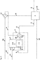
- Fig. 1 shows the schematic representation of a first embodiment of the method according to the invention.
- an oxyfuel combustion device 1 is coupled to a high-temperature solid electrolyte electrolysis device 2 with an anode compartment 2A and cathode compartment 2K (HT-SOEL).
- the oxyfuel combustion device 1 is supplied via 11 C-based fuels.
- the oxyfuel combustion device 1 typically includes components such as a recycle loop (not shown) for temperature control of the oxyfuel combustion and setting the combustion educt (ratio of electrolysis oxygen 3 from the HT-SOEL, carbon dioxide and water vapor), a device for separation of ash and other solid particles over 13 and possibly one Device for steam condensation (not shown) from the oxyfuel flue gas 4.
- the HT-SOEL 2 for the electrolysis of water vapor 9 is operated endothermically.
- the HT-SOEL 2 includes the heating of water vapor 9 by heat recuperation via heat exchangers 15, 16 of electrolysis hydrogen 5 and electrolysis oxygen 3.
- the generation of electrolysis hydrogen 5 takes place in the cathode 2K and the generation of electrolysis oxygen 3 takes place in the anode 2A.
- the electrolysis oxygen 3 serves as an oxidizing agent for the oxyfuel combustion 1. Excess electrolysis oxygen can be drawn off via 3a.
- the flue gas or carbon dioxide 4 obtained from the oxyfuel combustion is fed to the synthesis device 7 as an educt gas.
- the carbon dioxide 4 and the electrolysis hydrogen 5 are converted exothermically to form C-based secondary energy carriers or basic chemicals 8.
- Water or condensate from synthesis 7 can be drawn off via 14.
- a heat transfer takes place via 6 through heat transfer at the heat exchanger 17 from the exothermic synthesis for the production of water vapor 9.
- the synthesis device 7 typically contains components for temperature control and pressure adjustment of the synthesis educt, for educt generation by mixing carbon dioxide, hydrogen and possibly steam (to avoid carbon deposition), possibly for steam generation for the synthesis educt and for processing synthesis products (for example temperature control and possibly condensation of water vapor ).
- the C-based synthesis product can be a secondary energy carrier or basic chemicals such as methane, methanol, dimethyl ether, Fischer-Tropsch fuels, etc.
- the water vapor is added for endothermic HT electrolysis including heating of water vapor through heat recuperation of electrolysis oxygen via heat exchanger 15 and electrolysis hydrogen 5 via heat exchanger 16.
- heat exchanger 15 and 16 is arbitrary. This heat exchanger is also split into more than 2 heat exchangers possible. It is also possible to split the heat exchanger 17 into more than one heat exchanger.
- the indirect heat transfer by heat transfer 10 from the oxyfuel combustion 1 to the endothermic HT electrolysis 2 can be implemented using various options.
- the coupling takes place via heat exchangers (not shown) from the oxyfuel flue gas flow (hot side) into the HT-SOEL (cold side).
- Heat transfer via heat pipes from the oxyfuel flue gas flow and / or from the oxyfuel combustion chamber (hot side) to the HT-SOEL (cold side) is also possible.
- the heat transfer can also take place via a heat exchanger circuit from the oxyfuel flue gas flow and / or the oxyfuel combustion chamber (hot side) into the HT-SOEL (cold side).
- Electric power is supplied to the HT-SOEL via line 12. This is preferably done using electricity generated from renewable sources, for example from wind power or photovoltaic systems.
- Fig. 2 shows the schematic representation of a second embodiment of the method according to the invention.
- an oxyfuel combustion device 1 is coupled with a high-temperature solid electrolyte electrolysis 2 with an anode chamber 2A and a cathode chamber 2K (HT-SOEL).
- the oxyfuel combustion device 1 is supplied via 11 C-based fuels.
- the oxyfuel combustion device 1 typically contains components such as a recycle loop (not shown) for temperature control of the oxyfuel combustion and setting the combustion educt (ratio of electrolysis oxygen, carbon dioxide and water vapor), a device for separating ash and other particles 13, as well as means for partially recirculating synthesis gas 5 ′′ as additional fuel for setting the temperature and amount of the oxyfuel flue gas stream 4 '.
- a device for condensing water vapor from the oxyfuel flue gas 4' is not provided here.
- a flue gas 4 'obtained from oxyfuel combustion 1 and containing water vapor and carbon dioxide is used as cathode educt gas and thus the high-temperature waste heat obtained from oxyfuel combustion is sent directly to the cathode chamber 2K supplied to the HT-SOEL for endothermic HT electrolysis of oxyfuel flue gas.
- the synthesis device 7 comprises the same components and devices as in the case of the synthesis device 7 according to the first embodiment Fig. 1 .
- the preheating of the steam 9 for both the HT electrolysis and the oxyfuel combustion is still carried out by heat recuperation of electrolysis oxygen 3 via heat exchanger 15 and of electrolysis synthesis gas 5 'via heat exchanger 16.
- the order of the heat exchangers 15 and 16 can be as desired his.
- the number of heat exchangers is also not limited to 2. It is also possible to split the heat exchangers 15, 16, 17 into more than 3 heat exchangers. As with the embodiment in Fig. 1 For example, liquid water can be fed to the heat exchanger 17 via 9a to generate water vapor 9.
- the embodiment shown is optionally partially recirculated via 5 ′′ as additional fuel, including optionally water vapor condensation in the oxyfuel combustion 1 for the targeted setting of the temperature and amount of the oxyfuel flue gas stream 4 'for an optimized design of the endothermic HT electrolysis with low power consumption.
- Electric current preferably electricity generated from renewable sources, is supplied to the HT-SOEL via line 12.
- Fig. 3 shows a schematic representation of a third embodiment of the method according to the invention.
- the oxyfuel combustion is 1 and the HT-SOEL 2 spatially integrated, in which the HT-SOEL is carried out within the combustion chamber of the oxyfuel combustion device 1.
- the anode 2A corresponds to the endothermic HT electrolysis of the oxyfuel combustion 1.
- the anode 2A of the HT-SOEL with integrated oxyfuel combustion typically contains components such as a recycle loop (not shown) for temperature control of the oxyfuel combustion and setting of the combustion educt (ratio of electrolysis oxygen, carbon dioxide and water vapor), a device for the separation of ash and other particles via 13.
- the exothermic synthesis of C-based secondary energy carriers or basic chemicals 8 in the synthesis device 7 takes place analogously to that in FIG Fig. 2 described embodiment.
- Heat transfer also takes place via 6 through heat transfer at the heat exchanger 17 to generate water vapor 9.
- Water vapor 9 can both the cathode 2K and the Anode 2A are supplied for the targeted setting of the temperature and for an optimized design of the endothermic HT electrolysis with low power consumption.
- the water vapor 9 can also only be conducted to the cathode 2K instead of to the anode 2A.
- the synthesis gas 5 'produced can also be used to preheat at the cathode outlet.
- the number and sequence of heat exchangers is arbitrary. It is also possible to split the heat exchangers 17 and 18 into several heat exchangers.
- Fig. 4 shows a diagram of the thermodynamic parameters for the electrolysis of water / water vapor.
- This diagram shows the minimum decomposition voltages for the example of a temperature of 1300 K.
- a critical point of the method according to the invention is that the HT electrolysis is run in endothermic operation. This means that, according to this diagram, the operating point for the cell voltage applied per electrolysis cell lies between the electrical energy requirement deltaG and the total energy requirement deltaH. For the example shown of 1300 K, the applied cell voltage is between 0.91 and 1.29 V. With a cell voltage of> 1.29 V, operation would be exothermic and the HT electrolysis would thus produce heat. This means that external heat could no longer be injected in order to reduce the electrical energy requirement of the HT electrolysis.
- the decisive factor in the method according to the invention is that the missing energy requirement of the HT-SOEL in endothermic operation is covered by the waste heat from the oxyfuel combustion.
- Fig. 5 shows a diagram of the thermodynamic parameters for the electrolysis of carbon dioxide according to the second and third embodiment of the method according to the invention.
- the operating point for the cell voltage applied per electrolysis cell lies between the electrical energy requirement deltaG and the total energy requirement deltaH.
- the per electrolytic cell must be used applied cell voltage should be between 0.88 and 1.46 V in order to ensure endothermic operation. At> 1.46 V, operation becomes exothermic so that external heat can no longer be coupled in.
Description
Die Erfindung betrifft ein Verfahren zur Erzeugung von Kohlenstoff-basierten Sekundärenergieträgern oder Basischemikalien durch Kopplung einer Oxyfuel-Verbrennung Kohlenstoff-basierter Brennstoffe und einer Hochtemperatur-Festelektrolyt-Elektrolyse (HT-SOEL), wobei für die Oxyfuel-Verbrennung als Oxidationsmittel der bei der HT-SOEL erzeugte Sauerstoff eingesetzt wird und die aus der Oxyfuel-Verbrennung und/oder aus dem Kathodenraum der HT-SOEL gewonnenen Produktgase sowie gegebenenfalls zusätzlich extern zugeführter Wasserstoff in an sich bekannter Weise exotherm zu Kohlenstoff-basierten Sekundärenergieträgern oder Basischemikalien, wie etwa Methanol oder Kohlenwasserstoffen, wie etwa Methan, umgesetzt werden.The invention relates to a method for generating carbon-based secondary energy sources or basic chemicals by coupling an oxyfuel combustion of carbon-based fuels and a high-temperature solid electrolyte electrolysis (HT-SOEL), the oxidizing agent used for the oxyfuel combustion being the HT- SOEL generated oxygen is used and the product gases obtained from the oxyfuel combustion and / or from the cathode compartment of the HT-SOEL as well as any additional externally supplied hydrogen in a manner known per se exothermic to carbon-based secondary energy carriers or basic chemicals, such as methanol or hydrocarbons, such as methane.
Kohlenstoff-basierte (C-basierte) Brennstoffe umfassen beispielsweise Kohle, Erdgas, Öl, kohlenstoffhaltige Abfälle jeglicher Art, wie etwa Kunststoff oder Hausmüll, sonstige Kohlenwasserstoffe und biogene Brennstoffe.Carbon-based (C-based) fuels include, for example, coal, natural gas, oil, carbon-containing waste of all kinds, such as plastic or household waste, other hydrocarbons and biogenic fuels.
Biogene Brennstoffe sind Brennstoffe biogener, d.h. biologisch-organischer Herkunft und sind Teil der Biomasse. Biomasse ist die einzige erneuerbare Energiequelle, die Kohlenstoff enthält und daher prädestiniert ist für eine nachhaltige Erzeugung von Kohlenstoff-basierten (C-basierten) Sekundärenergieträgern, die vor allem in der Mobilität und chemischen Industrie nicht durch C-freie Energieträger ersetzt werden können.Biogenic fuels are fuels of biogenic, i.e. biological-organic origin, and are part of biomass. Biomass is the only renewable energy source that contains carbon and is therefore predestined for the sustainable production of carbon-based (C-based) secondary energy sources, which cannot be replaced by C-free energy sources, especially in the mobility and chemical industry.
Das technisch verfügbare Biomassepotential zur Herstellung von C-basierten Sekundärenergieträgern oder Basischemikalien ist limitiert. Ferner ist es aufgrund des geringen Wasserstoffanteils in der Biomasse mit konventionellen Verfahren nicht möglich, 100% des Kohlenstoffs in einen C-basierten Sekundärenergieträger zu überführen. Durch Einkopplung von elektrolytisch erzeugtem Wasserstoff bei der Umwandlung von Biomasse in einen C-basierten Sekundärenergieträger kann ein wesentlich höherer Ertrag an C-basierten Sekundärenergieträgern produziert werden.The technically available biomass potential for the production of C-based secondary energy carriers or basic chemicals is limited. Furthermore, due to the low hydrogen content in the biomass, it is not possible with conventional processes to convert 100% of the carbon into a C-based secondary energy carrier. By coupling in electrolytically generated hydrogen when converting biomass into a C-based secondary energy carrier, a significantly higher yield of C-based secondary energy carriers can be produced.
Die verfügbaren Verfahren zur Erzeugung von C-basierten Sekundärenergieträgern aus C-basierten Brennstoffen unterscheiden sich im Wesentlichen in der Konversionsrate des in den C-basierten Brennstoffen enthaltenen Kohlenstoffs und somit im Kohlenstoff-Konversionswirkungsgrad.The available methods for generating C-based secondary energy carriers from C-based fuels differ essentially in the conversion rate of the carbon contained in the C-based fuels and thus in the carbon conversion efficiency.
Die
Die
Die
Die im Stand der Technik bekannten Biomasse-Konversionsverfahren sind mit verschiedenen Nachteilen verbunden.The biomass conversion processes known in the prior art are associated with various disadvantages.
Im Falle der anaeroben Biogaserzeugung erfolgt keine Nutzung des bei der Wasserelektrolyse entstehenden Sauerstoffs. Ferner wird trotz Einkopplung von Elektrolyse-Wasserstoff nur eine unvollständige Kohlenstoffkonversion erreicht, da der kohlenstoffhaltige Gärrest nicht genutzt werden kann.In the case of anaerobic biogas production, the oxygen produced during water electrolysis is not used. Furthermore, in spite of the coupling in of electrolysis hydrogen, only an incomplete carbon conversion is achieved, since the carbon-containing fermentation residue cannot be used.
Im Falle der thermochemischen Vergasung besteht ein hoher Bedarf an erneuerbarer elektrischer Energie, die für die Bereitstellung von Wasserstoff aus der Wasserelektrolyse für eine möglichst hohe Kohlenstoffkonversion in einen Kohlenstoff-basierten Sekundärenergieträger benötigt wird.In the case of thermochemical gasification, there is a high demand for renewable electrical energy, which is required for the provision of hydrogen from water electrolysis for the highest possible carbon conversion into a carbon-based secondary energy carrier.
Die bei der exothermen Synthese von Kohlenstoff-basierten Sekundärenergieträgern anfallende Wärme weist ein Temperaturniveau von typischerweise etwa 250°C auf. Im Stand der Technik beschränkt sich die bislang erzielte Wärmeintegration aus dieser Abwärme auf die Verdampfungsenthalpie zur Wasserdampferzeugung für die Hochtemperatur-Wasserelektrolyse.The heat generated during the exothermic synthesis of carbon-based secondary energy sources has a temperature level of typically around 250 ° C. In the prior art, the heat integration achieved so far from this waste heat is limited to the enthalpy of vaporization for generating water vapor for high-temperature water electrolysis.
Der Erfindung liegt die Aufgabe zugrunde, unter Vermeidung der Nachteile des Standes der Technik ein effizientes und einfaches Verfahren zur Erzeugung von Kohlenstoff-basierten Sekundärenergieträgern oder Basischemikalien durch Kopplung einer Oxyfuel-Verbrennung C-basierter Brennstoffe und einer Hochtemperatur-Festelektrolyt-Elektrolyse vorzusehen, die eine möglichst vollständige Konversion des in den Brennstoffen enthaltenen Kohlenstoffs zu Kohlenstoff-basierten Sekundärenergieträgern oder Basischemikalien ermöglicht. Hierbei soll die Hochtemperatur-Festelektrolyt-Elektrolyse mit einem reduzierten elektrischen Energiebedarf durchführbar sein, um so den Gesamtwirkungsgrad des Kohlenstoff-Konversionsverfahrens zu steigern.The invention is based on the object, while avoiding the disadvantages of the prior art, to provide an efficient and simple method for the production of carbon-based secondary energy sources or basic chemicals by coupling an oxyfuel combustion of C-based fuels and a high-temperature solid electrolyte electrolysis As complete as possible conversion of the carbon contained in the fuels to carbon-based secondary energy carriers or basic chemicals is possible. In this case, the high-temperature solid electrolyte electrolysis should be able to be carried out with a reduced electrical energy requirement in order to increase the overall efficiency of the carbon conversion process.
Die obige Aufgabe wird gelöst durch ein Verfahren zur Erzeugung von C-basierten Sekundärenergieträgern gemäß Anspruch 1. Bevorzugte bzw. besonders zweckmäßige Ausgestaltungen der Erfindung sind in den Unteransprüchen angegeben.The above object is achieved by a method for generating C-based secondary energy carriers according to
Das erfindungsgemäße Verfahren ermöglicht eine gesteigerte bis vollständige Konversion des in den C-basierten Brennstoffen enthaltenen Kohlenstoffs - über die Stufe als Kohlendioxid - in Kohlenstoff-basierte Sekundärenergieträger oder Basischemikalien. Hierbei kann der gesamte Sauerstoffbedarf für die Oxyfuel-Verbrennung aus der Hochtemperatur-Festelektrolyt-Elektrolyse bereitgestellt werden.The method according to the invention enables an increased to complete conversion of the carbon contained in the C-based fuels - via the stage as carbon dioxide - into carbon-based secondary energy carriers or basic chemicals. In this case, the entire oxygen requirement for the oxyfuel combustion can be provided from the high-temperature solid electrolyte electrolysis.
Unter Oxyfuel-Verbrennung wird hierin die Verbrennung eines C-basierten Brennstoffs in einem Gasgemisch von Sauerstoff und vorzugsweise recycliertem Rauchgas (Recycle Loop), bestehend somit im Wesentlichen aus Sauerstoff, Wasserdampf und Kohlendioxid, verstanden. Der Sauerstoffbedarf bzw. das Stöchiometrieverhältnis der Oxyfuel-Verbrennung wird als λ definiert. ![]()
![]()
Daraus ergibt sich, dass für λ = 1 die für die Verbrennung notwendige, stöchiometrische Sauerstoffmenge zugegeben wird.This means that for λ = 1, the stoichiometric amount of oxygen required for combustion is added.
Das erfindungsgemäße Verfahren wird geeigneterweise im Bereich von 0,8 < λ < 1,2, vorzugsweise 0,95 < λ < 1,05, eingestellt.The method according to the invention is suitably set in the range of 0.8 <λ <1.2, preferably 0.95 <λ <1.05.
Die Oxyfuel-Verbrennung ist gegenüber der Vergasung eine technisch deutlich einfacher zu beherrschende Technologie. Die erfindungsgemäß erzielbaren, deutlich höheren Gesamtwirkungsgrade von den C-basierten Brennstoffen und Strom zum Kohlenstoff-basierten Sekundärenergieträger werden überraschenderweise dadurch erzielt, dass beim erfindungsgemäßen Verfahren Wärme auf unterschiedlichen Temperaturniveaus ausgekoppelt wird, insbesondere dadurch, dass ein Teil der für die Hochtemperatur-FestelektrolytElektrolyse erforderlichen elektrischen Energie durch Hochtemperaturwärme substituiert wird, beim erfindungsgemäßen Verfahren auch als "Abwärme III" bezeichnet, aus der Oxyfuel-Verbrennung der C-basierten Brennstoffe. Hierzu ist es erforderlich, die Hochtemperatur-Festelektrolyt-Elektrolyse im endothermen Betrieb zu fahren, in dem der Betriebspunkt für die pro Elektrolysezelle angelegte Zellspannung zwischen dem elektrischen Energiebedarf deltaG und dem gesamten Energiebedarf deltaH liegt. Dadurch resultiert ein hoher elektrischer Wirkungsgrad (ηElektr) der Hochtemperatur-Festelektrolyt-Elektrolyse von über 100% bis 140 %, definiert als ![]()
![]()
Die Vorteile des erfindungsgemäßen Verfahrens sind somit insbesondere eine nahezu vollständige Konversion des in den Brennstoffen enthaltenen Kohlenstoffs in Kohlenstoff-basierte Energieträger oder Basischemikalien sowie eine deutliche Erhöhung des Gesamtwirkungsgrades des Systems, insbesondere bewirkt durch eine Substitution elektrischer Energie für die Hochtemperatur-Festelektrolyt-Elektrolyse durch Hochtemperatur-Abwärme aus der Oxyfuel-Verbrennung.
Das erfindungsgemäße Verfahren umfasst mehrere Ausführungsformen.
Gemäß einer ersten Ausführungsform werden die Oxyfuel-Verbrennung und die HT-SOEL räumlich getrennt voneinander durchgeführt, wobei die Abwärme III aus der Oxyfuel-Verbrennung indirekt über mindestens einen Wärmeübertrager der HT-SOEL zugeleitet und ein aus der Oxyfuel-Verbrennung gewonnener Kohlendioxid-Massenstrom mit aus der HT-SOEL gewonnenem Wasserstoff zu C-basierten Sekundärenergieträgern oder Basischemikalien umgesetzt wird. Für die indirekte Wärmeübertragung kommen hierbei verschiedene Optionen in Frage. Beispielsweise erfolgt die Einkopplung über Wärmeübertrager vom Oxyfuel-Rauchgasstrom (heiße Seite) in die HT-SOEL (kalte Seite). Ebenfalls denkbar ist der Wärmetransfer über Heat-Pipes bzw. Wärmerohre von dem Oxyfuel-Rauchgasstrom und/oder vom Oxyfuel-Feuerungsraum (heiße Seite) in die HT-SOEL (kalte Seite). Desweiteren denkbar ist ein Wärmetransfer über einen Wärmeübertragerkreislauf von Oxyfuel-Rauchgasstrom und/oder Oxyfuel-Feuerungsraum (heiße Seite) in die HT-SOEL (kalte Seite). Stromabwärts des Wärmeübertragers kann vom Oxyfuel-Rauchgasstrom Wasser abgetrennt werden, um einen reinen Kohlendioxid-Massenstrom zu erzeugen, welcher der exothermen Synthese von C-basierten Sekundärenergieträgern oder Basischemikalien zugeführt wird. Wasserdampf wird der endothermen HT-SOEL zugeführt. Der durch Elektrolyse entstandene Wasserstoff dient für die exotherme Synthese der C-basierten Sekundärenergieträger oder Basischemikalien.The advantages of the method according to the invention are therefore, in particular, an almost complete conversion of the carbon contained in the fuels into carbon-based energy carriers or basic chemicals and a significant increase in the overall efficiency of the system, in particular caused by the substitution of electrical energy for high-temperature solid electrolyte electrolysis by high temperature -Waste heat from the oxyfuel combustion.
The method according to the invention comprises several embodiments.
According to a first embodiment, the oxyfuel combustion and the HT-SOEL are carried out spatially separate from one another, the waste heat III from the oxyfuel combustion being fed to the HT-SOEL indirectly via at least one heat exchanger a carbon dioxide mass flow obtained from oxyfuel combustion is converted with hydrogen obtained from the HT-SOEL to form C-based secondary energy carriers or basic chemicals. Various options are possible for indirect heat transfer. For example, the coupling takes place via heat exchangers from the oxyfuel flue gas flow (hot side) into the HT-SOEL (cold side). Heat transfer via heat pipes or heat pipes from the oxyfuel flue gas flow and / or from the oxyfuel combustion chamber (hot side) to the HT-SOEL (cold side) is also conceivable. A heat transfer via a heat exchanger circuit from the oxyfuel flue gas flow and / or oxyfuel combustion chamber (hot side) into the HT-SOEL (cold side) is also conceivable. Downstream of the heat exchanger, water can be separated from the oxyfuel flue gas flow in order to generate a pure carbon dioxide mass flow which is fed to the exothermic synthesis of C-based secondary energy carriers or basic chemicals. Water vapor is fed to the endothermic HT-SOEL. The hydrogen produced by electrolysis is used for the exothermic synthesis of the C-based secondary energy carriers or basic chemicals.
Gemäß einer zweiten Ausführungsform werden die Oxyfuel-Vertrennung und die HT-SOEL räumlich getrennt voneinander durchgeführt, wobei ein aus der Oxyfuel-Verbrennung gewonnenes, Wasserdampf und Kohlendioxid enthaltendes Rauchgas als Kathodeneduktgas und somit die aus der Oxyfuel-Verbrennung gewonnene Abwärme III direkt der HT-SOEL zugeführt, und ein aus der HT-SOEL gewonnene Synsthesegas, umfassend Wasserstoff, Kohlenmonoxid, Kohlendioxid und gegebenenfalls Wasserdampf, zu C-basierten Sekundärenergieträgern oder Basischemikalien umgesetzt wird. Der direkte Wärmetransfer von der Oxyfuel-Verbrennung zu der endothermen HT-Elektrolyse erfolgt somit durch die fühlbare Wärme des Oxyfuel-Rauchgases. Das Oxyfuel-Rauchgas dient hier als Kathodeneduktgas. In der HT-SOEL erfolgt somit neben der Elektrolyse des Wasserdampfes auch eine Elektrolyse von Kohlendioxid. Im Kathodenraum der HT-SOEL laufen dabei die folgenden Reaktionen ab:
- a) H2O → H2+1/2O2 (O2 wird über den Anodenraum abgeführt)
- b) CO2 → CO+1/2O2 (O2 wird über den Anodenraum abgeführt)
- c) CO2+H2 → CO+H2O (Retro-Shift-Reaktion)
- a) H 2 O → H 2 + 1 / 2O 2 (O 2 is discharged via the anode space)
- b) CO 2 → CO + 1 / 2O 2 (O 2 is discharged via the anode compartment)
- c) CO 2 + H 2 → CO + H 2 O (retro-shift reaction)
Das aus der HT-SOEL gewonnene Synthesegas umfasst somit im Wesentlichen Wasserstoff, Kohlenmonoxid sowie nicht umgesetzten Wasserdampf und Kohlendioxid. Gegebenenfalls kann eine Teilrückführung des Synthesegases als Zusatzbrennstoff inklusive gegebenenfalls Wasserdampf-Kondensation in die Oxyfuel-Verbrennung erfolgen zur gezielten Einstellung der Temperatur und Menge des Oxyfuel-Rauchgasstromes. Dies kann zu einer optimierten Auslegung der endothermen HT-Elektrolyse mit geringem elektrischen Stromverbrauch dienen.The synthesis gas obtained from the HT-SOEL thus essentially comprises hydrogen, carbon monoxide as well as unconverted water vapor and carbon dioxide. If necessary, the synthesis gas can be partially recirculated as an additional fuel, including water vapor condensation if necessary, in the oxyfuel combustion for the targeted adjustment of the temperature and amount of the oxyfuel flue gas flow. This can be used to optimize the design of the endothermic HT electrolysis with low electrical power consumption.
Gemäß einer dritten Ausführungsform sind die Oxyfuel-Verbrennung und die HT-SOEL räumlich integriert, indem die HT-SOEL innerhalb des Brennraums der Oxyfuel-Verbrennung durchgeführt wird. Bei dieser Ausführungsform wird ein aus der Oxyfuel-Verbrennung gewonnenes, Wasserdampf und Kohlendioxid enthaltendes Rauchgas als Kathodeneduktgas und somit die aus der Oxyfuel-Verbrennung gewonnene Abwärme III direkt der HT-SOEL zugeführt, und ein aus der HT-SOEL gewonnenes Synthesegas, umfassend Wasserstoff, Kohlenmonoxid, Kohlendioxid und gegebenenfalls Wasserdampf, sowie zusätzlich extern zugeführter Wasserstoff werden zu C-basierten Sekundärenergieträgern oder Basischemikalien umgesetzt. Bei dieser Ausführungsform wird somit die Hochtemperatur-Abwärme aus der Oxyfuel-Verbrennung direkt über das Rauchgas sowie zusätzlich über Wärmeleitung und Wärmestrahlung transportiert.According to a third embodiment, the oxyfuel combustion and the HT-SOEL are spatially integrated in that the HT-SOEL is carried out within the combustion chamber of the oxyfuel combustion. In this embodiment, a flue gas obtained from the oxyfuel combustion and containing water vapor and carbon dioxide is supplied as cathode educt gas and thus the waste heat III obtained from the oxyfuel combustion is fed directly to the HT-SOEL, and a synthesis gas obtained from the HT-SOEL, comprising hydrogen, Carbon monoxide, carbon dioxide and possibly water vapor, as well as additional externally supplied hydrogen, are converted into C-based secondary energy sources or basic chemicals. In this embodiment, the high-temperature waste heat from the oxyfuel combustion is thus transported directly via the flue gas and additionally via thermal conduction and thermal radiation.
Die Anode in der endothermen HT-Elektrolyse entspricht somit der Oxyfuel-Verbrennung. In Kathodenraum der endothermen HT-Elektrolyse wird unterstöchiometrisches Synthesegas erzeugt, das heißt dieses Synthesegas enthält für die nachfolgende Vollkonversion in der exothermen Synthese zu wenig Wasserstoff. Daher ist es erforderlich, zusätzlich Wasserstoff, beispielsweise aus einer weiteren Niedertemperatur (NT) - oder HT-Elektrolyse der exothermen Synthese zuzuführen. Im einfachsten Fall ist die Kathode der HT-SOEL als Rohrbündel ausgestaltet, wobei die Innenfläche der Rohre die Kathode und die Außenfläche die Anode bilden. An der Kathodenseite finden daher folgende Reaktionen statt:
- i)
H2O+2e- → H2+O2 2-
- ii)
CO2+2e- → CO+O2-
- i)
H 2 O + 2e - → H 2 + O 2 2-
- ii)
CO 2 + 2e - → CO + O 2-
An der Anodenseite findet folgende Reaktion statt:
iii)
O2- → 1/2O2+2e-
The following reaction takes place on the anode side:
iii)
O 2- → 1 / 2O 2 + 2e -
Dies bedeutet, dass Sauerstoff direkt in den Bereich der Anode-Oxyfuel-Verbrennung eintritt und die C-basierten Brennstoffe oxidiert. Der "Sauerstoffgenerator" sitzt somit direkt im Brennraum der Oxyfuel-Verbrennung.This means that oxygen goes directly into the area of the anode oxyfuel combustion and oxidizes the C-based fuels. The "oxygen generator" is located directly in the combustion chamber of the oxyfuel combustion.
Im Falle der externen Wasserstofferzeugung aus einer weiteren NT- oder HT-Elektrolyse, ist es ebenfalls möglich, den bei dieser externen Elektrolyse anfallenden Sauerstoff ebenfalls in den Bereich der Anode-Oxyfuel-Verbrennung einzuleiten.In the case of external hydrogen generation from a further LT or HT electrolysis, it is also possible to introduce the oxygen produced during this external electrolysis into the area of the anode-oxyfuel combustion.
Die obigen Ausführungsformen des erfindungsgemäßen Verfahrens können ebenfalls miteinander kombiniert werden.The above embodiments of the method according to the invention can also be combined with one another.
Beim erfindungsgemäßen Verfahren wird die HT-SOEL vorzugsweise bei Temperaturen von 600 - 1100 °C, weiter vorzugsweise von 800 - 1050 °C, durchgeführt.In the process according to the invention, the HT-SOEL is preferably carried out at temperatures of 600-1100.degree. C., more preferably 800-1050.degree.
Die Abwärme I aus der exothermen Synthese von C-basierten Sekundärenergieträgern oder Basischemikalien liegt vorzugsweise bei einem Temperaturniveau von weniger als 500 °C, typischerweise weniger als 300 °C, insbesondere bevorzugt bei etwa 250 °C.The waste heat I from the exothermic synthesis of C-based secondary energy sources or basic chemicals is preferably at a temperature level of less than 500.degree. C., typically less than 300.degree. C., particularly preferably about 250.degree.
Die Abwärme II, welche den Produkten Wasserstoff und Sauerstoff aus der HT-SOEL innewohnt, liegt vorzugsweise bei einem Temperaturniveau unterhalb der Betriebstemperatur der HT-SOEL, typischerweise bei Temperaturen von weniger als 800 °C.The waste heat II, which is inherent in the products hydrogen and oxygen from the HT-SOEL, is preferably at a temperature level below the operating temperature of the HT-SOEL, typically at temperatures below 800 ° C.
Die Hochtemperatur-Abwärme aus der Oxyfuel-Verbrennung, das heißt die Abwärme III, liegt vorzugsweise bei einem Temperaturniveau von oberhalb der Betriebstemperatur der HT-SOEL, weiter vorzugsweise von über 800 °C. Das Abgas aus der Oxyfuel-Verbrennung ist im Wesentlichen ein CO2/H2O-Rauchgas, aus dem sich durch Auskondensieren von H2O auf einfache Weise ein reiner CO2-Massenstrom erzeugen lässt. Dieses CO2 wird gemäß der ersten Ausführungsform des erfindungsgemäßen Verfahrens mit dem bei der HT-SOEL anfallenden H2 zu C-basierten Kraftstoffen oder Grundchemikalien umgesetzt. Hierbei kann der Kohlenstoff aus dem C-basierten Brennstoff zu nahezu 100 % in einen C-basierten Kraftstoff konvertiert werden. Gegenüber der konventionellen Erzeugung von Biokraftstoffen wird hierbei der Kraftstoffertrag um ein Mehrfaches gesteigert. Bei herkömmlichem Bio-Diesel oder Bioethanol wird nur ca. 1/4 des Biomasse-Kohlenstoffs zu Kraftstoff-Kohlenstoff konvertiert.The high-temperature waste heat from the oxyfuel combustion, that is to say the waste heat III, is preferably at a temperature level above the operating temperature of the HT-SOEL, more preferably above 800 ° C. The exhaust gas from the oxyfuel combustion is essentially a CO 2 / H 2 O flue gas, from which a pure CO 2 mass flow can be easily generated by condensing out H 2 O. This CO 2 is according to First embodiment of the method according to the invention with the H 2 produced in the HT-SOEL converted into C-based fuels or basic chemicals. Almost 100% of the carbon from the C-based fuel can be converted into a C-based fuel. Compared to the conventional production of biofuels, the fuel yield is increased several times over. With conventional bio-diesel or bioethanol, only about 1/4 of the biomass carbon is converted to fuel carbon.
Beim erfindungsgemäßen Verfahren ist es möglich, den gesamten Sauerstoffbedarf für die Oxyfuel-Verbrennung durch die HT-SOEL zu decken. Dies hat den Vorteil, einen H2O/CO2-Strom für die HT-SOEL und einen H2O/H2/CO2/CO-Strom für die Synthese zu generieren.With the method according to the invention it is possible to cover the entire oxygen requirement for the oxyfuel combustion by the HT-SOEL. This has the advantage of generating an H 2 O / CO 2 flow for the HT-SOEL and an H 2 O / H 2 / CO 2 / CO flow for the synthesis.
Beim erfindungsgemäßen Verfahren können alle üblichen C-basierten Brennstoffe eingesetzt werden. Vorzugsweise werden biogene Brennstoffe eingesetzt.All customary C-based fuels can be used in the process according to the invention. Biogenic fuels are preferably used.
Als biogene Brennstoffe können Festbrennstoffe, wie Brennholz, Gärrest oder Klärschlamm und/oder Flüssigbrennstoffe, wie etwa Pflanzenöle einschließlich Slurries, wie etwa Biopyrolyseöl/Koks und/oder Brenngase, wie Faulgase oder Klärgase, eingesetzt werden.Solid fuels such as firewood, digestate or sewage sludge and / or liquid fuels such as vegetable oils including slurries such as biopyrolysis oil / coke and / or fuel gases such as digester gases or sewage gases can be used as biogenic fuels.
Die elektrische Energie für die HT-SOEL stammt vorzugsweise aus einer regenerativen Stromerzeugung. Für die regenerative Stromerzeugung können übliche Anlagen eingesetzt werden, wie Windkraftanlagen, Photovoltaikanlagen, Geothermiekraftwerke, Biomassekraftwerke, Wasserkraftwerke, Solarthermiekraftwerke oder Kombinationen daraus.The electrical energy for the HT-SOEL comes preferably from regenerative power generation. Conventional systems can be used for regenerative power generation, such as wind turbines, photovoltaic systems, geothermal power plants, biomass power plants, hydropower plants, solar thermal power plants or combinations thereof.
Als Kohlenstoff-basierte Sekundärenergieträger oder Basischemikalien werden insbesondere Kohlenwasserstoffe, wie etwa Methan oder Fischer-Tropsch-Kohlenwasserstoffe oder chemische Verbindungen, bestehend aus Kohlenstoff, Wasserstoff und Sauerstoff, wie beispielsweise Methanol, Ethanol oder Dimethylether, hergestellt. Die Synthese der C-basierten Sekundärenergieträger oder Basischemikalien erfolgt nach üblichen, dem Fachmann bekannten Methoden, beispielsweise bei Temperaturen im Bereich von 200 °C-600 °C.Hydrocarbons such as methane or Fischer-Tropsch hydrocarbons or chemical compounds consisting of carbon, hydrogen and oxygen such as methanol, ethanol or dimethyl ether are produced as carbon-based secondary energy carriers or basic chemicals. The synthesis of the C-based secondary energy sources or basic chemicals takes place according to customary methods known to the person skilled in the art, for example at temperatures in the range from 200.degree. C.-600.degree.
-
Fig. 1 zeigt die schematische Darstellung einer ersten Ausführungsform des erfindungsgemäßen Verfahrens.Fig. 1 shows the schematic representation of a first embodiment of the method according to the invention. -
Fig. 2 zeigt die schematische Darstellung einer zweiten Ausführungsform des erfindungsgemäßen Verfahrens.Fig. 2 shows the schematic representation of a second embodiment of the method according to the invention. -
Fig. 3 zeigt die schematische Darstellung einer dritten Ausführungsform des erfindungsgemäßen Verfahrens.Fig. 3 shows the schematic representation of a third embodiment of the method according to the invention. -
Fig. 4 zeigt ein Diagramm der thermodynamischen Parameter für die Elektrolyse von Wasser/Wasserdampf.Fig. 4 shows a diagram of the thermodynamic parameters for the electrolysis of water / water vapor. -
Fig. 5 zeigt ein Diagramm der thermodynamischen Parameter für die Elektrolyse von Kohlendioxid.Fig. 5 shows a diagram of the thermodynamic parameters for the electrolysis of carbon dioxide.
Bevorzugte Ausführungsformen des erfindungsgemäßen Verfahrens werden unter Bezugnahme auf die beigefügten Figuren nachfolgend näher erläutert.Preferred embodiments of the method according to the invention are explained in more detail below with reference to the accompanying figures.
Das aus der Oxyfuel-Verbrennung gewonnene Rauchgas bzw. Kohlendioxid 4 wird als Eduktgas der Syntheseeinrichtung 7 zugeführt. In der Syntheseeinrichtung 7 wird das Kohlendioxid 4 und der Elektrolyse-Wasserstoff 5 exotherm zu C-basierten Sekundärenergieträgern oder Basischemikalien 8 umgesetzt. Wasser bzw. Kondensat aus der Synthese 7 kann über 14 abgezogen werden. Über 6 erfolgt ein Wärmetransfer durch Wärmeübertragung beim Wärmeübertrager 17 aus der exothermen Synthese zur Erzeugung von Wasserdampf 9.The flue gas or
Die Syntheseeinrichtung 7 beinhaltet typischerweise Komponenten zur Temperierung und Druckeinstellung des Syntheseedukts, zur Edukterzeugung durch Mischen von Kohlendioxid, Wasserstoff und gegebenenfalls Wasserdampf (zur Vermeidung von Kohlenstoffablagerung), gegebenenfalls zur Wasserdampferzeugung für das Syntheseedukt sowie zur Aufbereitung von Syntheseprodukten (beispielsweise Temperierung und gegebenenfalls Kondensation von Wasserdampf). Bei dem C-basierten Syntheseprodukt kann es sich um Sekundärenergieträger oder um Grundchemikalien, wie beispielsweise Methan, Methanol, Dimethylether, Fischer-Tropsch-Kraftstoffe etc., handeln.The
Über 9 erfolgt die Wasserdampfzugabe zur endothermen HT-Elektrolyse inklusive Erhitzung von Wasserdampf durch Wärmerekuperation von Elektrolyse-Sauerstoff über Wärmeübertrager 15 und Elektrolyse-Wasserstoff 5 über Wärmeübertrager 16. Es ist darauf hinzuweisen, dass die Anzahl und Reihenfolge der Wärmeübertrager 15 und 16 beliebig ist. Ebenfalls ist eine Aufsplittung dieser Wärmeübertrager in mehr als 2 Wärmeübertrager möglich. Ebenfalls ist eine Aufsplittung von Wärmeübertrager 17 in mehr als einen Wärmeübertrager möglich.Via 9, the water vapor is added for endothermic HT electrolysis including heating of water vapor through heat recuperation of electrolysis oxygen via
Der indirekte Wärmetransfer durch Wärmeübertragung 10 aus der Oxyfuel-Verbrennung 1 zu der endothermen HT-Elektrolyse 2 ist über verschiedene Optionen verwirklichbar. Beispielsweise erfolgt die Einkopplung über Wärmeübertrager (nicht gezeigt) vom Oxyfuel-Rauchgasstrom (heiße Seite) in die HT-SOEL (kalte Seite). Ebenfalls möglich ist der Wärmetransfer über Wärmerohre vom Oxyfuel-Rauchgasstrom und/oder vom Oxyfuel-Feuerungsraum (heiße Seite) in die HT-SOEL (kalte Seite). Schließlich kann der Wärmetransfer auch über einen Wärmeübertragerkreislauf von Oxyfuel-Rauchgasstrom und/oder Oxyfuel-Feuerungsraum (heiße Seite) in die HT-SOEL (kalte Seite) erfolgen.The indirect heat transfer by
Die Zuleitung von elektrischem Strom zu der HT-SOEL erfolgt über Leitung 12. Hierzu dient vorzugsweise regenerativ erzeugter Strom, beispielsweise aus Windkraft- oder Photovoltaikanlagen.Electric power is supplied to the HT-SOEL via
Gemäß dieser Ausführungsform wird ein aus der Oxyfuel-Verbrennung 1 gewonnenes, Wasserdampf und Kohlendioxid enthaltendes Rauchgas 4' als Kathodeneduktgas und somit die aus der Oxyfuel-Verbrennung gewonnene Hochtemperatur-Abwärme direkt der Kathodenkammer 2K der HT-SOEL zur endothermen HT-Elektrolyse von Oxyfuel-Rauchgas zugeführt. Ein aus der Kathodenkammer 2K erhaltenes Synthesegas 5', bestehend im Wesentlichen aus Wasserstoff, Kohlenmonoxid sowie nicht umgesetztem Kohlendioxid und gegebenenfalls Wasserdampf, wird der Syntheseeinrichtung 7 für die exotherme Synthese von C-basierten Sekundärenergieträgern oder Basischemikalien zugeführt. Die Syntheseeinrichtung 7 umfasst die gleichen Komponenten und Vorrichtungen wie im Falle der Syntheseeinrichtung 7 der ersten Ausführungsform gemäß
Der Wärmetransfer durch Wärmeübertragung über 6 und den Wärmeübertrager 17 aus der exothermen Synthese 7 zur Erzeugung von Wasserdampf 9 für die endotherme HT-Elektrolyse 2 erfolgt analog
Die Vorerhitzung des Wasserdampfes 9 sowohl für die HT-Elektrolyse als auch die Oxyfuel-Verbrennung erfolgt weiterhin durch Wärmerekuperation von Elektrolyse-Sauerstoff 3 über Wärmeübertrager 15 als auch von Elektrolyse-Synthesegas 5' über Wärmeübertrager 16. Die Reihenfolge der Wärmeübertrager 15 und 16 kann beliebig sein. Ebenfalls ist die Anzahl der Wärmeübertrager nicht auf 2 beschränkt. Ferner ist eine Aufsplittung der Wärmeübertrager 15, 16, 17 in mehr als 3 Wärmeübertrager möglich. Wie bei der Ausführungsform in
Bei der in
Ebenfalls wird wie bei
Infolge einer stöchiometrischen Oxyfuel-Verbrennung von C-basiertem Brennstoff 11 wird auf der Anodenseite 2A kein Sauerstoffüberschuss erzielt. Neben Wasserdampf wird somit das im Oxyfüel-Rauchgas 4' enthaltene Kohlendioxid als Eduktgas der Kathode umgesetzt zur Erzielung eines Synthesegases aus Wasserstoff, Kohlenmonoxid und nicht umgesetztem Wasserdampf und Kohlendioxid.As a result of the stoichiometric oxyfuel combustion of C-based
Die exotherme Synthese von C-basierten Sekudärenergieträgern oder Basischemikalien 8 in der Syntheseeinrichtung 7 erfolgt analog der in
Wie bei den
Claims (13)
- Process for generating carbon-based secondary energy carriers or base chemicals (8) by coupling oxyfuel combustion (1) of carbon-based fuels (11) and high-temperature solid electrolyte electrolysis (HT-SOEL) (2, 2A, 2K), wherein, for the oxyfuel combustion, oxygen generated from the HT-SOEL is used as an oxidizing agent (3), and the product gases (4, 4', 5, 5) obtained from the oxyfuel combustion and/or from the cathode chamber (2K) of the HT-SOEL, and, optionally, additionally externally supplied hydrogen (16), are reacted exothermically in a manner known per se to form carbon-based secondary energy carriers or base chemicals (8),
wherein, in the process, heat is coupled out at different temperature levels in such a way that waste heat I (6) from the exothermic synthesis (7) of carbon-based secondary energy carriers or base chemicals (8) is used to generate steam for the HT-SOEL (2, 2A, 2K), waste heat II inherent in the product gases (3, 4, 4', 5, 5') of the HT- SOEL is used to preheat the steam (9) to be supplied to the HT-SOEL, and waste heat III (10) obtained from the oxyfuel combustion is fed to the HT-SOEL (2, 2A, 2K),
wherein the HT- SOEL is operated in endothermic operation, in which the operating point for the cell voltage applied per electrolysis cell is between the electrical energy requirement deltaG and the total energy requirement deltaH, and the missing energy requirement of the HT-SOEL in endothermic operation is covered by the waste heat III (10),
and wherein the electrical efficiency for the HT-SOEL is more than 100% and up to 140% if the electrical efficiency (ηElektr) of the HT-SOEL is defined according to the following formula (I)
- Process according to claim 1, wherein the oxyfuel combustion (1) and the HT-SOEL (2, 2A, 2K) are carried out spatially separately from each other, the waste heat III (10) from the oxyfuel combustion is fed indirectly to the HT SOEL via at least one heat exchanger, and a carbon dioxide mass flow (4) obtained from the oxyfuel combustion is reacted with hydrogen (5) obtained from the HT-SOEL to form carbon-based secondary energy carriers or base chemicals (8).
- Process according to claim 1, wherein the oxyfuel combustion (1) and the HT-SOEL (2, 2A, 2K) are carried out spatially separately from one another, as a cathode reactant gas a flue gas (4') obtained from the oxyfuel combustion and containing steam and carbon dioxide, and thus the waste heat III obtained from the oxyfuel combustion, is supplied directly to the HT-SOEL (2K), and a synthesis gas (5') obtained from the HT-SOEL and comprising hydrogen, carbon monoxide, carbon dioxide and optionally steam is reacted to form carbon-based secondary energy carriers or base chemicals (8).
- Process according to claim 1, wherein the oxyfuel combustion (1) and the HT-SOEL (2, 2A, 2K) are spatially integrated by the HT-SOEL being carried out within the combustion chamber of the oxyfuel combustion, as the cathode reactant gas a flue gas (4') obtained from the oxyfuel combustion and containing steam and carbon dioxide, and thus the waste heat III obtained from the oxyfuel combustion is supplied directly to the HT-SOEL (2K), and a synthesis gas (5') obtained from the HT-SOEL and comprising hydrogen, carbon monoxide, carbon dioxide and optionally steam, as well as additionally externally supplied hydrogen (16), are reacted to form carbon-based secondary energy carriers or base chemicals (8).
- Process according to at least one of the preceding claims, wherein the HT-SOEL (2) is operated at temperatures of 600-1100°C, preferably 800-1050°C.
- Process according to at least one of the preceding claims, wherein the waste heat I (6) has a temperature level of < 500°C, preferably approximately 250°C.
- Process according to at least one of the preceding claims, wherein the waste heat II has a temperature level below the operating temperature of the HT-SOEL.
- Process according to at least one of the preceding claims, wherein the waste heat III (10) has a temperature level above the operating temperature of the HT-SOEL, typically above 800°C, preferably above 800-1000°C.
- Process according to at least one of the preceding claims, wherein the entire oxygen requirement for the oxyfuel combustion (1) is covered by the HT-SOEL (2).
- Process according to at least one of the preceding claims, wherein biogenic fuels (11) in the form of solid fuels and/or liquid fuels and/or fuel gases are used as the carbon-based fuels (11), wherein the solid fuels are firewood, digestate or sewage sludge, wherein the liquid fuels are vegetable oils, and wherein the fuel gases are digester gases or sewage gases.
- Process according to at least one of the preceding claims, wherein electrical energy from regenerative power generation is used as electrical energy (12) for the HT-SOEL (2).
- Process according to claim 11, wherein the regenerative power generation takes place by means of wind power plants, photovoltaic plants, geothermal power plants, biomass power plants, hydropower plants, solar thermal power plants or combinations thereof.
- Process according to at least one of the preceding claims, wherein hydrocarbons and/or chemical compounds consisting of carbon, hydrogen and oxygen are generated as the carbon-based secondary energy carriers or base chemicals.
Applications Claiming Priority (2)
| Application Number | Priority Date | Filing Date | Title |
|---|---|---|---|
| DE102015226111.5A DE102015226111A1 (en) | 2015-12-18 | 2015-12-18 | Process for the production of carbon-based secondary fuels or basic chemicals |
| PCT/EP2016/080942 WO2017102817A1 (en) | 2015-12-18 | 2016-12-14 | Method for generating carbon-based secondary energy carriers or basic chemical products |
Publications (2)
| Publication Number | Publication Date |
|---|---|
| EP3390693A1 EP3390693A1 (en) | 2018-10-24 |
| EP3390693B1 true EP3390693B1 (en) | 2021-01-27 |
Family
ID=57708554
Family Applications (1)
| Application Number | Title | Priority Date | Filing Date |
|---|---|---|---|
| EP16820204.2A Active EP3390693B1 (en) | 2015-12-18 | 2016-12-14 | Method for generating carbon-based secondary energy carriers or basic chemical products |
Country Status (4)
| Country | Link |
|---|---|
| EP (1) | EP3390693B1 (en) |
| DE (1) | DE102015226111A1 (en) |
| DK (1) | DK3390693T3 (en) |
| WO (1) | WO2017102817A1 (en) |
Families Citing this family (12)
| Publication number | Priority date | Publication date | Assignee | Title |
|---|---|---|---|---|
| JP6744242B2 (en) * | 2017-03-10 | 2020-08-19 | 株式会社東芝 | Chemical reaction system |
| DE102018213482A1 (en) | 2018-08-10 | 2020-02-13 | Siemens Aktiengesellschaft | Provision of carbon dioxide using oxygen-based combustion |
| EP3670705B1 (en) * | 2018-12-21 | 2022-02-02 | L'air Liquide, Societe Anonyme Pour L'etude Et L'exploitation Des Procedes Georges Claude | Carbon dioxide conversion process |
| DE102019125641A1 (en) * | 2019-09-24 | 2021-03-25 | Dr. Ing. H.C. F. Porsche Aktiengesellschaft | Method and device for storing electrical energy |
| DE102019127037A1 (en) * | 2019-10-08 | 2021-04-08 | Forschungszentrum Jülich GmbH | Production of carbon monoxide |
| EP4048651A1 (en) * | 2019-12-20 | 2022-08-31 | Siemens Energy Global GmbH & Co. KG | Apparatus and method for utilizing off-gases from a power-to-x system |
| US11867092B2 (en) * | 2020-03-06 | 2024-01-09 | Siemens Energy Global GmbH & Co. KG | System having a combustion power plant and an electrolysis unit, and method for operating a system of this type |
| DE102020109448A1 (en) * | 2020-04-03 | 2021-10-07 | Forschungszentrum Jülich GmbH | Process for producing a synthetic fuel and system for carrying out such a process |
| DE102020210478A1 (en) | 2020-08-18 | 2022-02-24 | Thyssenkrupp Ag | Process for hydrogen synthesis using heat from a heat network using a high-temperature electrolysis system |
| AT525899B1 (en) * | 2022-06-23 | 2023-09-15 | Avl List Gmbh | Synthesis system, fuel cell system, fuel cell system and method for producing synthesis gas |
| AT525898B1 (en) * | 2022-06-23 | 2023-09-15 | Avl List Gmbh | Fuel cell system, fuel cell system and method for producing synthesis gas |
| AT526077B1 (en) * | 2022-06-23 | 2023-11-15 | Avl List Gmbh | Fuel cell system, fuel cell system and method for producing synthesis gas |
Citations (1)
| Publication number | Priority date | Publication date | Assignee | Title |
|---|---|---|---|---|
| US20110041740A1 (en) * | 2009-08-20 | 2011-02-24 | Reilly Timothy J | Recuperative combustion system |
Family Cites Families (7)
| Publication number | Priority date | Publication date | Assignee | Title |
|---|---|---|---|---|
| DE102006035893A1 (en) | 2006-07-31 | 2008-02-07 | Wolf, Bodo M., Dr. | Process for the reprocessing of combustion products of fossil fuels |
| US8366902B2 (en) * | 2008-03-24 | 2013-02-05 | Battelle Energy Alliance, Llc | Methods and systems for producing syngas |
| DE102009018126B4 (en) | 2009-04-09 | 2022-02-17 | Zentrum für Sonnenenergie- und Wasserstoff-Forschung Baden-Württemberg | Power supply system and operating procedures |
| EP2360230A1 (en) | 2010-02-16 | 2011-08-24 | Siemens Aktiengesellschaft | Method and device for exploiting the emissions of a power plant |
| DE102012214907B4 (en) * | 2012-08-22 | 2015-05-21 | Siemens Aktiengesellschaft | Steam power plant for generating electrical energy according to the oxyfuel process |
| FR3004179B1 (en) * | 2013-04-08 | 2015-05-01 | Commissariat Energie Atomique | METHODS FOR OBTAINING COMBUSTIBLE GAS FROM WATER ELECTROLYSIS (EHT) OR CO-ELECTROLYSIS WITH H2O / CO2 WITHIN THE SAME ENCLOSURE, CATALYTIC REACTOR AND SYSTEM THEREOF |
| WO2014170200A1 (en) * | 2013-04-19 | 2014-10-23 | Gunnar Sanner | Methods for production of liquid hydrocarbons from energy, co2 and h2o |
-
2015
- 2015-12-18 DE DE102015226111.5A patent/DE102015226111A1/en not_active Ceased
-
2016
- 2016-12-14 WO PCT/EP2016/080942 patent/WO2017102817A1/en active Application Filing
- 2016-12-14 DK DK16820204.2T patent/DK3390693T3/en active
- 2016-12-14 EP EP16820204.2A patent/EP3390693B1/en active Active
Patent Citations (1)
| Publication number | Priority date | Publication date | Assignee | Title |
|---|---|---|---|---|
| US20110041740A1 (en) * | 2009-08-20 | 2011-02-24 | Reilly Timothy J | Recuperative combustion system |
Also Published As
| Publication number | Publication date |
|---|---|
| DE102015226111A1 (en) | 2017-06-22 |
| WO2017102817A1 (en) | 2017-06-22 |
| DK3390693T3 (en) | 2021-05-03 |
| EP3390693A1 (en) | 2018-10-24 |
Similar Documents
| Publication | Publication Date | Title |
|---|---|---|
| EP3390693B1 (en) | Method for generating carbon-based secondary energy carriers or basic chemical products | |
| EP2426236B1 (en) | Method and fuel generation assembly for the carbon dioxide-neutral compensation of energy peaks and troughs in the generation of electrical energy and/or for producing a fuel containing hydrocarbons | |
| EP3019582B1 (en) | Flexibly operable power plant and method for the operation thereof | |
| EP2751307B1 (en) | Power supply system, in particular for the field of building technology | |
| EP2146926B1 (en) | Method for producing synthesis gas | |
| DE102012103458B4 (en) | Plant and process for the ecological production and storage of electricity | |
| DE102013219681B4 (en) | Method and system for storing electrical energy | |
| CN108779050A (en) | Produce the integrated system and method for methanol product | |
| EP2491998A1 (en) | Method for recycling combustion products of fossil fuels | |
| EP2360230A1 (en) | Method and device for exploiting the emissions of a power plant | |
| WO2009135558A2 (en) | Device and method for the electrothermal-chemical gasification of biomass | |
| EP2892983A2 (en) | Ecological sequestration of carbon dioxide/increase of bio-energy obtainable through biomass | |
| DE102015005940A1 (en) | Method for improving the integration of renewable energy sources into the existing energy system by converting electrical energy into chemical energy with intermediate storage of the liquefied CO, thereby achieving a reduction of the CO2 emission | |
| DE102012103703A1 (en) | Solar thermal / combined cycle hybrid power plant and solar reformer for use therein | |
| EP3967654A1 (en) | Method and system for the production of hydrogen through steam reforming and high temperature electrolysis | |
| EP0361612A2 (en) | Method for generating electricity | |
| EP3526335A1 (en) | Method and device for producing organic compounds from biogas | |
| DE102018132736A1 (en) | Process and plant for producing one or more gaseous reaction products in a fired reactor | |
| EP4148109A1 (en) | Energy and hydrogen logistics | |
| WO2020151928A1 (en) | Method for operating a plant for synthesizing a chemical product | |
| DE102012221286A1 (en) | Microbiological biomethane production with hydrogen from the thermal gasification of carbonaceous feedstocks | |
| DE102011015824A1 (en) | Aircraft fuel cell system, aircraft and use of a synthetic fuel | |
| DE10355552A1 (en) | Extracting electrical energy from gasification of material containing carbon involves multi-stage gasification, oxidation stage in which intermediate gasification products are oxidized while feeding in oxygen, fuel cell module cathode gas | |
| EP4357440A1 (en) | Method for producing a target product and corresponding facility | |
| DE102015017254B3 (en) | Process for the integration of renewable electricity using carbon monoxide |
Legal Events
| Date | Code | Title | Description |
|---|---|---|---|
| STAA | Information on the status of an ep patent application or granted ep patent |
Free format text: STATUS: UNKNOWN |
|
| STAA | Information on the status of an ep patent application or granted ep patent |
Free format text: STATUS: THE INTERNATIONAL PUBLICATION HAS BEEN MADE |
|
| PUAI | Public reference made under article 153(3) epc to a published international application that has entered the european phase |
Free format text: ORIGINAL CODE: 0009012 |
|
| STAA | Information on the status of an ep patent application or granted ep patent |
Free format text: STATUS: REQUEST FOR EXAMINATION WAS MADE |
|
| 17P | Request for examination filed |
Effective date: 20180712 |
|
| AK | Designated contracting states |
Kind code of ref document: A1 Designated state(s): AL AT BE BG CH CY CZ DE DK EE ES FI FR GB GR HR HU IE IS IT LI LT LU LV MC MK MT NL NO PL PT RO RS SE SI SK SM TR |
|
| AX | Request for extension of the european patent |
Extension state: BA ME |
|
| DAV | Request for validation of the european patent (deleted) | ||
| DAX | Request for extension of the european patent (deleted) | ||
| RAP1 | Party data changed (applicant data changed or rights of an application transferred) |
Owner name: ZENTRUM FUER SONNENENERGIE- UND WASSERSTOFF-FORSCH |
|
| STAA | Information on the status of an ep patent application or granted ep patent |
Free format text: STATUS: EXAMINATION IS IN PROGRESS |
|
| 17Q | First examination report despatched |
Effective date: 20191028 |
|
| REG | Reference to a national code |
Ref country code: DE Ref legal event code: R079 Ref document number: 502016012323 Country of ref document: DE Free format text: PREVIOUS MAIN CLASS: C25B0001040000 Ipc: C25B0001000000 |
|
| GRAP | Despatch of communication of intention to grant a patent |
Free format text: ORIGINAL CODE: EPIDOSNIGR1 |
|
| STAA | Information on the status of an ep patent application or granted ep patent |
Free format text: STATUS: GRANT OF PATENT IS INTENDED |
|
| RIC1 | Information provided on ipc code assigned before grant |
Ipc: C10G 2/00 20060101ALI20200622BHEP Ipc: C25B 3/04 20060101ALI20200622BHEP Ipc: C07C 29/151 20060101ALI20200622BHEP Ipc: C07C 41/01 20060101ALI20200622BHEP Ipc: C10L 3/08 20060101ALI20200622BHEP Ipc: C25B 15/08 20060101ALI20200622BHEP Ipc: C25B 1/00 20060101AFI20200622BHEP Ipc: C25B 1/04 20060101ALI20200622BHEP |
|
| INTG | Intention to grant announced |
Effective date: 20200721 |
|
| GRAS | Grant fee paid |
Free format text: ORIGINAL CODE: EPIDOSNIGR3 |
|
| GRAA | (expected) grant |
Free format text: ORIGINAL CODE: 0009210 |
|
| STAA | Information on the status of an ep patent application or granted ep patent |
Free format text: STATUS: THE PATENT HAS BEEN GRANTED |
|
| AK | Designated contracting states |
Kind code of ref document: B1 Designated state(s): AL AT BE BG CH CY CZ DE DK EE ES FI FR GB GR HR HU IE IS IT LI LT LU LV MC MK MT NL NO PL PT RO RS SE SI SK SM TR |
|
| REG | Reference to a national code |
Ref country code: GB Ref legal event code: FG4D Free format text: NOT ENGLISH |
|
| REG | Reference to a national code |
Ref country code: CH Ref legal event code: EP |
|
| REG | Reference to a national code |
Ref country code: AT Ref legal event code: REF Ref document number: 1358420 Country of ref document: AT Kind code of ref document: T Effective date: 20210215 |
|
| REG | Reference to a national code |
Ref country code: IE Ref legal event code: FG4D Free format text: LANGUAGE OF EP DOCUMENT: GERMAN |
|
| REG | Reference to a national code |
Ref country code: DE Ref legal event code: R096 Ref document number: 502016012323 Country of ref document: DE |
|
| REG | Reference to a national code |
Ref country code: DK Ref legal event code: T3 Effective date: 20210426 |
|
| REG | Reference to a national code |
Ref country code: NL Ref legal event code: MP Effective date: 20210127 |
|
| REG | Reference to a national code |
Ref country code: NO Ref legal event code: T2 Effective date: 20210127 |
|
| REG | Reference to a national code |
Ref country code: LT Ref legal event code: MG9D |
|
| PG25 | Lapsed in a contracting state [announced via postgrant information from national office to epo] |
Ref country code: GR Free format text: LAPSE BECAUSE OF FAILURE TO SUBMIT A TRANSLATION OF THE DESCRIPTION OR TO PAY THE FEE WITHIN THE PRESCRIBED TIME-LIMIT Effective date: 20210428 Ref country code: FI Free format text: LAPSE BECAUSE OF FAILURE TO SUBMIT A TRANSLATION OF THE DESCRIPTION OR TO PAY THE FEE WITHIN THE PRESCRIBED TIME-LIMIT Effective date: 20210127 Ref country code: HR Free format text: LAPSE BECAUSE OF FAILURE TO SUBMIT A TRANSLATION OF THE DESCRIPTION OR TO PAY THE FEE WITHIN THE PRESCRIBED TIME-LIMIT Effective date: 20210127 Ref country code: PT Free format text: LAPSE BECAUSE OF FAILURE TO SUBMIT A TRANSLATION OF THE DESCRIPTION OR TO PAY THE FEE WITHIN THE PRESCRIBED TIME-LIMIT Effective date: 20210527 Ref country code: LT Free format text: LAPSE BECAUSE OF FAILURE TO SUBMIT A TRANSLATION OF THE DESCRIPTION OR TO PAY THE FEE WITHIN THE PRESCRIBED TIME-LIMIT Effective date: 20210127 Ref country code: BG Free format text: LAPSE BECAUSE OF FAILURE TO SUBMIT A TRANSLATION OF THE DESCRIPTION OR TO PAY THE FEE WITHIN THE PRESCRIBED TIME-LIMIT Effective date: 20210427 |
|
| PG25 | Lapsed in a contracting state [announced via postgrant information from national office to epo] |
Ref country code: RS Free format text: LAPSE BECAUSE OF FAILURE TO SUBMIT A TRANSLATION OF THE DESCRIPTION OR TO PAY THE FEE WITHIN THE PRESCRIBED TIME-LIMIT Effective date: 20210127 Ref country code: LV Free format text: LAPSE BECAUSE OF FAILURE TO SUBMIT A TRANSLATION OF THE DESCRIPTION OR TO PAY THE FEE WITHIN THE PRESCRIBED TIME-LIMIT Effective date: 20210127 Ref country code: PL Free format text: LAPSE BECAUSE OF FAILURE TO SUBMIT A TRANSLATION OF THE DESCRIPTION OR TO PAY THE FEE WITHIN THE PRESCRIBED TIME-LIMIT Effective date: 20210127 Ref country code: SE Free format text: LAPSE BECAUSE OF FAILURE TO SUBMIT A TRANSLATION OF THE DESCRIPTION OR TO PAY THE FEE WITHIN THE PRESCRIBED TIME-LIMIT Effective date: 20210127 |
|
| PG25 | Lapsed in a contracting state [announced via postgrant information from national office to epo] |
Ref country code: IS Free format text: LAPSE BECAUSE OF FAILURE TO SUBMIT A TRANSLATION OF THE DESCRIPTION OR TO PAY THE FEE WITHIN THE PRESCRIBED TIME-LIMIT Effective date: 20210527 |
|
| REG | Reference to a national code |
Ref country code: DE Ref legal event code: R097 Ref document number: 502016012323 Country of ref document: DE |
|
| PG25 | Lapsed in a contracting state [announced via postgrant information from national office to epo] |
Ref country code: SM Free format text: LAPSE BECAUSE OF FAILURE TO SUBMIT A TRANSLATION OF THE DESCRIPTION OR TO PAY THE FEE WITHIN THE PRESCRIBED TIME-LIMIT Effective date: 20210127 Ref country code: CZ Free format text: LAPSE BECAUSE OF FAILURE TO SUBMIT A TRANSLATION OF THE DESCRIPTION OR TO PAY THE FEE WITHIN THE PRESCRIBED TIME-LIMIT Effective date: 20210127 Ref country code: EE Free format text: LAPSE BECAUSE OF FAILURE TO SUBMIT A TRANSLATION OF THE DESCRIPTION OR TO PAY THE FEE WITHIN THE PRESCRIBED TIME-LIMIT Effective date: 20210127 |
|
| PG25 | Lapsed in a contracting state [announced via postgrant information from national office to epo] |
Ref country code: SK Free format text: LAPSE BECAUSE OF FAILURE TO SUBMIT A TRANSLATION OF THE DESCRIPTION OR TO PAY THE FEE WITHIN THE PRESCRIBED TIME-LIMIT Effective date: 20210127 Ref country code: RO Free format text: LAPSE BECAUSE OF FAILURE TO SUBMIT A TRANSLATION OF THE DESCRIPTION OR TO PAY THE FEE WITHIN THE PRESCRIBED TIME-LIMIT Effective date: 20210127 |
|
| PLBE | No opposition filed within time limit |
Free format text: ORIGINAL CODE: 0009261 |
|
| STAA | Information on the status of an ep patent application or granted ep patent |
Free format text: STATUS: NO OPPOSITION FILED WITHIN TIME LIMIT |
|
| 26N | No opposition filed |
Effective date: 20211028 |
|
| PG25 | Lapsed in a contracting state [announced via postgrant information from national office to epo] |
Ref country code: AL Free format text: LAPSE BECAUSE OF FAILURE TO SUBMIT A TRANSLATION OF THE DESCRIPTION OR TO PAY THE FEE WITHIN THE PRESCRIBED TIME-LIMIT Effective date: 20210127 Ref country code: ES Free format text: LAPSE BECAUSE OF FAILURE TO SUBMIT A TRANSLATION OF THE DESCRIPTION OR TO PAY THE FEE WITHIN THE PRESCRIBED TIME-LIMIT Effective date: 20210127 |
|
| PG25 | Lapsed in a contracting state [announced via postgrant information from national office to epo] |
Ref country code: SI Free format text: LAPSE BECAUSE OF FAILURE TO SUBMIT A TRANSLATION OF THE DESCRIPTION OR TO PAY THE FEE WITHIN THE PRESCRIBED TIME-LIMIT Effective date: 20210127 |
|
| PG25 | Lapsed in a contracting state [announced via postgrant information from national office to epo] |
Ref country code: IT Free format text: LAPSE BECAUSE OF FAILURE TO SUBMIT A TRANSLATION OF THE DESCRIPTION OR TO PAY THE FEE WITHIN THE PRESCRIBED TIME-LIMIT Effective date: 20210127 |
|
| PG25 | Lapsed in a contracting state [announced via postgrant information from national office to epo] |
Ref country code: IS Free format text: LAPSE BECAUSE OF FAILURE TO SUBMIT A TRANSLATION OF THE DESCRIPTION OR TO PAY THE FEE WITHIN THE PRESCRIBED TIME-LIMIT Effective date: 20210527 |
|
| PG25 | Lapsed in a contracting state [announced via postgrant information from national office to epo] |
Ref country code: MC Free format text: LAPSE BECAUSE OF FAILURE TO SUBMIT A TRANSLATION OF THE DESCRIPTION OR TO PAY THE FEE WITHIN THE PRESCRIBED TIME-LIMIT Effective date: 20210127 |
|
| REG | Reference to a national code |
Ref country code: CH Ref legal event code: PL |
|
| GBPC | Gb: european patent ceased through non-payment of renewal fee |
Effective date: 20211214 |
|
| REG | Reference to a national code |
Ref country code: BE Ref legal event code: MM Effective date: 20211231 |
|
| PG25 | Lapsed in a contracting state [announced via postgrant information from national office to epo] |
Ref country code: LU Free format text: LAPSE BECAUSE OF NON-PAYMENT OF DUE FEES Effective date: 20211214 Ref country code: IE Free format text: LAPSE BECAUSE OF NON-PAYMENT OF DUE FEES Effective date: 20211214 Ref country code: GB Free format text: LAPSE BECAUSE OF NON-PAYMENT OF DUE FEES Effective date: 20211214 |
|
| PG25 | Lapsed in a contracting state [announced via postgrant information from national office to epo] |
Ref country code: FR Free format text: LAPSE BECAUSE OF NON-PAYMENT OF DUE FEES Effective date: 20211231 Ref country code: BE Free format text: LAPSE BECAUSE OF NON-PAYMENT OF DUE FEES Effective date: 20211231 |
|
| PG25 | Lapsed in a contracting state [announced via postgrant information from national office to epo] |
Ref country code: LI Free format text: LAPSE BECAUSE OF NON-PAYMENT OF DUE FEES Effective date: 20211231 Ref country code: CH Free format text: LAPSE BECAUSE OF NON-PAYMENT OF DUE FEES Effective date: 20211231 |
|
| REG | Reference to a national code |
Ref country code: AT Ref legal event code: MM01 Ref document number: 1358420 Country of ref document: AT Kind code of ref document: T Effective date: 20211214 |
|
| PG25 | Lapsed in a contracting state [announced via postgrant information from national office to epo] |
Ref country code: AT Free format text: LAPSE BECAUSE OF NON-PAYMENT OF DUE FEES Effective date: 20211214 |
|
| PG25 | Lapsed in a contracting state [announced via postgrant information from national office to epo] |
Ref country code: HU Free format text: LAPSE BECAUSE OF FAILURE TO SUBMIT A TRANSLATION OF THE DESCRIPTION OR TO PAY THE FEE WITHIN THE PRESCRIBED TIME-LIMIT; INVALID AB INITIO Effective date: 20161214 |
|
| PG25 | Lapsed in a contracting state [announced via postgrant information from national office to epo] |
Ref country code: NL Free format text: LAPSE BECAUSE OF NON-PAYMENT OF DUE FEES Effective date: 20210127 Ref country code: CY Free format text: LAPSE BECAUSE OF FAILURE TO SUBMIT A TRANSLATION OF THE DESCRIPTION OR TO PAY THE FEE WITHIN THE PRESCRIBED TIME-LIMIT Effective date: 20210127 |
|
| PGFP | Annual fee paid to national office [announced via postgrant information from national office to epo] |
Ref country code: NO Payment date: 20231218 Year of fee payment: 8 Ref country code: DK Payment date: 20231219 Year of fee payment: 8 Ref country code: DE Payment date: 20231220 Year of fee payment: 8 |