EP3390180B2 - Verfahren zum lösen einer elektromotorisch aktuierten, ersten bremseinrichtung, steuergerät für ein bremssystem eines fahrzeugs, bremssystem für ein fahrzeug, und fahrzeug mit einem solchen bremssystem - Google Patents
Verfahren zum lösen einer elektromotorisch aktuierten, ersten bremseinrichtung, steuergerät für ein bremssystem eines fahrzeugs, bremssystem für ein fahrzeug, und fahrzeug mit einem solchen bremssystem Download PDFInfo
- Publication number
- EP3390180B2 EP3390180B2 EP16791405.0A EP16791405A EP3390180B2 EP 3390180 B2 EP3390180 B2 EP 3390180B2 EP 16791405 A EP16791405 A EP 16791405A EP 3390180 B2 EP3390180 B2 EP 3390180B2
- Authority
- EP
- European Patent Office
- Prior art keywords
- brake
- vehicle
- braking device
- brake device
- actuated
- Prior art date
- Legal status (The legal status is an assumption and is not a legal conclusion. Google has not performed a legal analysis and makes no representation as to the accuracy of the status listed.)
- Active
Links
- 238000000034 method Methods 0.000 title claims description 39
- 230000008569 process Effects 0.000 description 16
- 230000007246 mechanism Effects 0.000 description 3
- 230000003213 activating effect Effects 0.000 description 2
- 230000001934 delay Effects 0.000 description 2
- XDDAORKBJWWYJS-UHFFFAOYSA-N glyphosate Chemical compound OC(=O)CNCP(O)(O)=O XDDAORKBJWWYJS-UHFFFAOYSA-N 0.000 description 2
- 230000009467 reduction Effects 0.000 description 2
- 230000004913 activation Effects 0.000 description 1
- 238000000594 atomic force spectroscopy Methods 0.000 description 1
- 230000003111 delayed effect Effects 0.000 description 1
- 230000001419 dependent effect Effects 0.000 description 1
- 230000000994 depressogenic effect Effects 0.000 description 1
- 230000000694 effects Effects 0.000 description 1
- 230000002349 favourable effect Effects 0.000 description 1
- 230000009347 mechanical transmission Effects 0.000 description 1
- 230000008092 positive effect Effects 0.000 description 1
- 239000007787 solid Substances 0.000 description 1
Images
Classifications
-
- B—PERFORMING OPERATIONS; TRANSPORTING
- B60—VEHICLES IN GENERAL
- B60T—VEHICLE BRAKE CONTROL SYSTEMS OR PARTS THEREOF; BRAKE CONTROL SYSTEMS OR PARTS THEREOF, IN GENERAL; ARRANGEMENT OF BRAKING ELEMENTS ON VEHICLES IN GENERAL; PORTABLE DEVICES FOR PREVENTING UNWANTED MOVEMENT OF VEHICLES; VEHICLE MODIFICATIONS TO FACILITATE COOLING OF BRAKES
- B60T13/00—Transmitting braking action from initiating means to ultimate brake actuator with power assistance or drive; Brake systems incorporating such transmitting means, e.g. air-pressure brake systems
- B60T13/10—Transmitting braking action from initiating means to ultimate brake actuator with power assistance or drive; Brake systems incorporating such transmitting means, e.g. air-pressure brake systems with fluid assistance, drive, or release
- B60T13/58—Combined or convertible systems
- B60T13/588—Combined or convertible systems both fluid and mechanical assistance or drive
-
- B—PERFORMING OPERATIONS; TRANSPORTING
- B60—VEHICLES IN GENERAL
- B60T—VEHICLE BRAKE CONTROL SYSTEMS OR PARTS THEREOF; BRAKE CONTROL SYSTEMS OR PARTS THEREOF, IN GENERAL; ARRANGEMENT OF BRAKING ELEMENTS ON VEHICLES IN GENERAL; PORTABLE DEVICES FOR PREVENTING UNWANTED MOVEMENT OF VEHICLES; VEHICLE MODIFICATIONS TO FACILITATE COOLING OF BRAKES
- B60T13/00—Transmitting braking action from initiating means to ultimate brake actuator with power assistance or drive; Brake systems incorporating such transmitting means, e.g. air-pressure brake systems
- B60T13/10—Transmitting braking action from initiating means to ultimate brake actuator with power assistance or drive; Brake systems incorporating such transmitting means, e.g. air-pressure brake systems with fluid assistance, drive, or release
- B60T13/66—Electrical control in fluid-pressure brake systems
- B60T13/662—Electrical control in fluid-pressure brake systems characterised by specified functions of the control system components
-
- B—PERFORMING OPERATIONS; TRANSPORTING
- B60—VEHICLES IN GENERAL
- B60T—VEHICLE BRAKE CONTROL SYSTEMS OR PARTS THEREOF; BRAKE CONTROL SYSTEMS OR PARTS THEREOF, IN GENERAL; ARRANGEMENT OF BRAKING ELEMENTS ON VEHICLES IN GENERAL; PORTABLE DEVICES FOR PREVENTING UNWANTED MOVEMENT OF VEHICLES; VEHICLE MODIFICATIONS TO FACILITATE COOLING OF BRAKES
- B60T13/00—Transmitting braking action from initiating means to ultimate brake actuator with power assistance or drive; Brake systems incorporating such transmitting means, e.g. air-pressure brake systems
- B60T13/74—Transmitting braking action from initiating means to ultimate brake actuator with power assistance or drive; Brake systems incorporating such transmitting means, e.g. air-pressure brake systems with electrical assistance or drive
- B60T13/741—Transmitting braking action from initiating means to ultimate brake actuator with power assistance or drive; Brake systems incorporating such transmitting means, e.g. air-pressure brake systems with electrical assistance or drive acting on an ultimate actuator
-
- F—MECHANICAL ENGINEERING; LIGHTING; HEATING; WEAPONS; BLASTING
- F16—ENGINEERING ELEMENTS AND UNITS; GENERAL MEASURES FOR PRODUCING AND MAINTAINING EFFECTIVE FUNCTIONING OF MACHINES OR INSTALLATIONS; THERMAL INSULATION IN GENERAL
- F16D—COUPLINGS FOR TRANSMITTING ROTATION; CLUTCHES; BRAKES
- F16D55/00—Brakes with substantially-radial braking surfaces pressed together in axial direction, e.g. disc brakes
- F16D55/02—Brakes with substantially-radial braking surfaces pressed together in axial direction, e.g. disc brakes with axially-movable discs or pads pressed against axially-located rotating members
- F16D55/22—Brakes with substantially-radial braking surfaces pressed together in axial direction, e.g. disc brakes with axially-movable discs or pads pressed against axially-located rotating members by clamping an axially-located rotating disc between movable braking members, e.g. movable brake discs or brake pads
- F16D55/224—Brakes with substantially-radial braking surfaces pressed together in axial direction, e.g. disc brakes with axially-movable discs or pads pressed against axially-located rotating members by clamping an axially-located rotating disc between movable braking members, e.g. movable brake discs or brake pads with a common actuating member for the braking members
- F16D55/225—Brakes with substantially-radial braking surfaces pressed together in axial direction, e.g. disc brakes with axially-movable discs or pads pressed against axially-located rotating members by clamping an axially-located rotating disc between movable braking members, e.g. movable brake discs or brake pads with a common actuating member for the braking members the braking members being brake pads
- F16D55/226—Brakes with substantially-radial braking surfaces pressed together in axial direction, e.g. disc brakes with axially-movable discs or pads pressed against axially-located rotating members by clamping an axially-located rotating disc between movable braking members, e.g. movable brake discs or brake pads with a common actuating member for the braking members the braking members being brake pads in which the common actuating member is moved axially, e.g. floating caliper disc brakes
-
- B—PERFORMING OPERATIONS; TRANSPORTING
- B60—VEHICLES IN GENERAL
- B60Y—INDEXING SCHEME RELATING TO ASPECTS CROSS-CUTTING VEHICLE TECHNOLOGY
- B60Y2400/00—Special features of vehicle units
- B60Y2400/81—Braking systems
Definitions
- the invention relates to a method for releasing a brake device actuated by an electric motor, a control unit for a brake system of a vehicle, a brake system for a vehicle with such a control unit, and a vehicle with such a brake system.
- a clamping force is preferably generated via a spindle-nut system, with the spindle-nut system preferably being arranged in a brake piston.
- a braking device has longer application times for application and release processes due to the electromechanical control and the design-related mechanical transmission by means of gear stages, in particular in comparison to purely hydraulic braking devices.
- a so-called cavalier start can be considered, which is to take place starting from a state with an applied parking brake device actuated by an electric motor.
- the parking brake device must then be activated in the release direction before the vehicle can pick up speed.
- the starting torque can be available before the holding force of the parking brake device is reduced, particularly in the case of powerful vehicles or electrically driven vehicles in which the starting torque builds up quickly or is already available when the engine is off.
- the document relates to a method for actuating an electromechanical parking brake device in the case of a brake that can be actuated by means of an electromechanical actuator, in which the actuator consists of an electric motor and a reduction gear connected downstream of the electric motor for converting a rotary movement into a translatory movement, and in which the electromechanical parking brake device is a Locking mechanism is formed, which can prevent the rotational movement of the actuator in the release direction and can only be released again by further tightening.
- the object of the invention is to create a method for releasing an electric motor-actuated first braking device, a control unit for a braking system, a braking system for a vehicle, and a vehicle with such a braking system, in which case the disadvantages mentioned do not occur.
- an improved, in particular faster release of the braking device actuated by an electric motor should be possible.
- the object is achieved by creating a method with the features of claim 1 for releasing an electric motor-actuated first braking device for a vehicle, wherein when the first braking device is in the applied state, a second braking device for the vehicle is actuated in an application direction in order to act on one of the two Braking devices commonly associated brake piston to generate a predetermined clamping force.
- the first braking device is driven in a release direction before the second braking device reaches the predetermined application force. There is therefore no waiting until the predetermined application force has been fully built up by the second braking device; instead, the first braking device and the second braking device are activated in parallel, with the first braking device being activated even before the second braking device has built up the predetermined application force.
- the first braking device is relieved by the second braking device, which accelerates the release process, and is activated at a comparatively early point in time, which also has a positive effect on accelerating the release process. Overall, therefore, the first braking device can be released very quickly.
- a braking device is understood to mean, in particular, a device that is set up to decelerate a vehicle and/or to make it stationary when stationary must be held so that the vehicle does not roll away - even on an uphill or downhill slope.
- the first braking device is preferably an automated parking brake (APB), particularly preferably an automated parking brake which has electric motors which are located directly on the wheel brakes of the vehicle, in particular on wheel brakes on a rear axle.
- APB-M Motor on Caliper
- An applied state is understood to mean a state of the braking device in which it develops a braking force.
- the braking device can in particular be displaced between an applied state and a released state, with the braking device developing no braking force in the released state.
- An application direction is accordingly understood to mean a direction in which the braking device is actuated, in which it is shifted from the released state to the applied state.
- a release direction is accordingly understood to mean a direction in which the braking device is shifted from the applied state to the released state.
- the brake piston is assigned to the first brake device and the second brake device in common, which means that both the first brake device and the second brake device act on the same brake piston.
- a brake piston is understood to mean in particular an element which carries a brake lining and is set up and arranged in order to move the brake lining against a brake disc.
- the first braking device preferably has a spindle-nut system which is arranged in the brake piston.
- the second braking device preferably acts on the brake piston in a different way, in particular hydraulically.
- the second braking device differs in particular from the first braking device.
- the second braking device is preferably not actuated by an electric motor, but in some other way, in particular hydraulically.
- a service brake of a vehicle is preferably used as the second braking device, that is to say a braking device which is used to decelerate the vehicle during normal, error-free driving operation.
- the fact that the first braking device is actuated before the second braking device reaches the predetermined application force includes that the first braking device is actuated before the second braking device is actuated in the application direction, or that the first braking device is actuated after the second braking device is in the Application direction is controlled. In both cases, the advantages mentioned above result.
- the first braking device and the second braking device are activated simultaneously.
- This enables the braking devices to be activated in a manner that is as simple as it is particularly rapid.
- the first braking device and the second braking device are preferably controlled simultaneously.
- a control unit for a braking system which has the first braking device and the second braking device, transmits actuation commands to the two braking devices simultaneously, in particular at the same time, or that the control unit transmits these commands - insofar as it is not necessary for the commands to be transmitted at the same time is set up - immediately one after the other, that is to say in particular without a delay or dead time specifically provided for this purpose.
- the application force is generated hydraulically by the second braking device.
- the second brake device is a service brake of a vehicle, which preferably has a hydraulic brake circuit with a brake booster for building up a hydraulic brake pressure.
- An electronic brake force distribution system (Electronic Stability Program - ESP) can also be used as the second braking device, in particular if this is set up to implement an active hydraulic pressure build-up.
- the second braking device it is possible for the second braking device to have a vacuum-free, in particular electric or electronic, brake booster.
- the method is only carried out when the driver requests a rapid start when the accelerator pedal is fully depressed, in particular a so-called kickdown.
- the driver requests a particularly quick start-up process, so that the advantages of the method are realized here in a special way.
- the object is also achieved by creating a control device for a braking system of a vehicle, which is set up to carry out one of the previously described embodiments of the method.
- the advantages that have already been explained in connection with the method are realized in particular in connection with the control device.
- the object is also achieved by creating a braking system for a vehicle, which has a first braking device actuated by an electric motor, the braking system also having a second braking device that is different from the first braking device.
- the braking system also has a control unit which is set up to carry out a method according to one of the previously described embodiments, or which is designed according to one of the previously described exemplary embodiments.
- the advantages that have already been explained in connection with the method and the control unit are realized in particular.
- the first braking system is preferably designed as an automatic parking brake (APB).
- APB automatic parking brake
- at least two electric motors are preferably arranged on at least two wheel brakes, in particular on a rear axle of the vehicle, so that the first braking device is designed as an APB-M system (motor on caliper).
- the second braking device is preferably designed as a service brake of a vehicle, in particular as a hydraulic braking device. It is possible for the second braking device to be in the form of an electronic brake force distribution system and/or to have an electric or electronic brake booster.
- the brake system preferably has a pressure modulation device that is set up to provide high pressure dynamics. A very rapid pressure build-up can thus be generated, and a brake pressure that has built up can also be reduced again very quickly, which enables a particularly rapid start-up process.
- the braking system preferably has a force modulation device which has high dynamics. This also enables a rapid start-up process in a particularly favorable manner.
- the vehicle is preferably designed as a motor vehicle, in particular as a passenger car, as a truck or as a commercial vehicle.
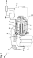
- FIG 1 shows a brake system 1 of a vehicle 101 in a simplified sectional view, with a first brake device 102 actuated by an electric motor and a second brake device 103 which is not actuated by an electric motor. between which a brake disc 4 connected to a wheel of the vehicle 101 can be clamped or clamped.
- the brake caliper 2 is assigned a hydraulic actuator 5, which is configured here as a hydraulic brake device and is assigned to the second brake device 103, which has a brake piston 6 which can be actuated hydraulically in order to clamp the brake disc 4 between the brake pads 3 if necessary.
- a braking torque is applied to the brake disc 4 and thus applied to the wheels, which serves to decelerate the vehicle 101.
- the first braking device 102 is designed as a parking brake device, in particular as an automatic parking brake, and has an electromotive actuator 7, which is formed by an electric motor 8, an actuator mechanism 9, which is embodied here as a spindle mechanism, and an actuator element 10.
- An output shaft of the electric motor 8 is connected in a rotationally fixed manner to a drive spindle 11 of the actuator gear 9 .
- the drive spindle 11 has an external thread that interacts with an internal thread of the actuator element 10 that can be moved along the drive spindle 11 . By activating the electric motor 8, the drive spindle 11 is thus set into a rotational movement in order to displace the actuator element 10.
- the actuator element 10 can be displaced from a release position into an application position and back, with the actuator element 10 in the application position displacing the brake piston 6 against the brake disc 4 and thereby applying the brake caliper 2 .
- the brake piston 6 is accordingly associated with the first braking device 102 and the second braking device 103 in common.
- the actuator element 10 is arranged coaxially to the brake piston 6 and within the brake piston 6 .
- the actuator gear 9 converts the rotational movement of the drive spindle 11 into a translational movement of the actuator element 10.
- the wheel brake device corresponds to known wheel brake devices.
- a control unit 104 is provided, which is set up to control first braking device 102 and second braking device 103 .
- first braking device 102 If the first braking device 102 is clamped, a clamping force acts via the brake piston 6 on the actuator element 10 and thus at the same time on the drive spindle 11, the first braking device 102 being designed to be self-locking, so that very high clamping forces act. Thus, when the first braking device 102 is released, a high load torque acts on the electric motor 8, which hinders and, in particular, delays its starting.
- a hydraulic brake pressure can be built up by means of the second brake device 103, which forces the brake piston 6 in the application direction and thus relieves the actuator element 10.
- the electric motor 8 can then start up without load and very quickly reach its no-load speed, which considerably accelerates the release process.
- second braking device 103 is therefore preferably actuated in the applied state of first braking device 102 in the application direction in order to generate a predetermined application force on brake piston 6, with first braking device 102 being actuated in the release direction before the second braking device 103 reaches the predetermined clamping force.
- the first braking device 102 and the second braking device 103 are preferably activated simultaneously, in particular at the same time.
- first braking device 102 and second braking device 103 are actuated when a driver of vehicle 101 wishes to start off, which can be recognized in particular based on a pedal position of vehicle 101 and/or based on a gear selection by the driver. It is possible for the release method described here to be carried out only when an accelerator pedal position or actuation is detected which goes beyond a predetermined limit position or a predetermined actuation speed of the accelerator pedal. According to the invention, this is the case with a so-called kickdown, that is to say a complete depression of the accelerator pedal in order to carry out a rapid start.
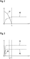
- FIG 2 shows a diagrammatic representation of a release process of the first braking device 102 without assistance from the second braking device 103.
- a first, solid curve K1 is plotted against the time t, which represents the course of an application force when the first braking device 102 is released, and a second, dashed curve K2, which represents the speed profile of the electric motor 8 during the release process. It turns out that the application force according to the first curve K1 is reduced only relatively slowly, and it only completely disappears at a first point in time t 1 .
- the torque build-up--as represented by the second curve K2--of the electric motor 8 takes place with a delay, because it starts up under load, with an idle speed essentially only being reached at the first point in time t.sub.1 .
- the total release process is significantly delayed.
- FIG 3 a diagrammatic representation of a release process of the first braking device 102 with the support of the second braking device 103 is shown. Elements that are the same and have the same function are provided with the same reference symbols, so that reference is made to the previous description.
- a third, dot-dash curve K3 is also plotted against time here, which represents the course of an application force which is applied by the second braking device 103 . This shows that the application force acting as a brake on the electric motor 8 is built up by the second braking device 103 to the same extent as the application force is built up according to the third curve K3 according to the first curve K1. The electric motor 8 is therefore increasingly relieved, and this can take place very quickly, in particular due to the high dynamics of the second braking device 103 .
- first braking device 102 and the second braking device 103 are controlled in parallel, so that this effect and the relief of the electric motor 8 very quickly - as can be seen from the second curve K2 - the idling speed can be reached.
- control unit 104 brake system 1 and vehicle 101 rapid release of first brake device 102 is possible, in which case a driver's desire to move away quickly, in particular in the form of a cavalier start, can be supported.
Landscapes
- Engineering & Computer Science (AREA)
- Mechanical Engineering (AREA)
- Transportation (AREA)
- General Engineering & Computer Science (AREA)
- Regulating Braking Force (AREA)
- Braking Systems And Boosters (AREA)
- Braking Arrangements (AREA)
Description
- Die Erfindung betrifft ein Verfahren zum Lösen einer elektromotorisch aktuierten Bremseinrichtung, ein Steuergerät für ein Bremssystem eines Fahrzeugs, ein Bremssystem für ein Fahrzeug mit einem solchen Steuergerät, und ein Fahrzeug mit einem solchen Bremssystem.
- Bei einer elektromotorisch aktuierten Bremseinrichtung wird vorzugsweise eine Klemmkraft über ein Spindel-Mutter-System erzeugt, wobei das Spindel-Mutter-System vorzugsweise in einem Bremskolben angeordnet ist. Eine solche Bremseinrichtung hat aufgrund der elektromechanischen Ansteuerung und der konstruktiv bedingten mechanischen Übersetzung mittels Getriebestufen insbesondere im Vergleich zu rein hydraulischen Bremseinrichtungen längere Applikationszeiten für Zuspann- und Lösevorgänge. Dabei kann es insbesondere dazu kommen, dass die Zeit für einen Klemmkraftabbau mit einem zügigen Anfahrwunsch eines Fahrers eines Fahrzeugs in Konflikt gerät. Als Beispielfall, um das Potential dieses Verfahrens aufzuzeigen, kann ein sogenannter Kavalierstart betrachtet werden, der ausgehend von einem Zustand mit zugespannter, elektromotorisch aktuierter Parkbremseinrichtung erfolgen soll. Die Parkbremseinrichtung muss dann in Löserichtung angesteuert werden, bevor das Fahrzeug Geschwindigkeit aufnehmen kann. Insbesondere bei leistungsstarken Fahrzeugen, oder bei elektrisch angetriebenen Fahrzeugen, bei denen das Anfahrdrehmoment schnell aufgebaut beziehungsweise bereits bei stehendem Motor zur Verfügung steht, kann das Anfahrmoment bereitstehen, bevor die Haltekraft der Parkbremseinrichtung abgebaut ist.
- Es zeigt sich, dass ein Hauptgrund für das vergleichsweise langsame Lösen einer elektromotorisch aktuierten Bremseinrichtung darin zu sehen ist, dass solche Systeme selbsthemmend ausgelegt sind und aufgrund der Zuspannkraft eine hohe Reibung erfahren, sodass ein Drehzahlaufbau des Elektromotors unter vergleichsweise hoher Last erfolgt, wobei eine Leerlaufdrehzahl erst relativ spät erreicht werden kann. Aus der
WO 2005/073043 A1 ist es bekannt, eine erste, elektromotorisch aktuierte Bremseinrichtung durch Aktivieren einer zweiten, hydraulisch aktuierten Bremseinrichtung zu entlasten, und so ein verbessertes Lösen der ersten Bremseinrichtung zu ermöglichen. Bei einer solchen Vorgehensweise wird allerdings zuerst ein gewünschter Hydraulikdruck vollständig aufgebaut, bevor die elektromotorisch aktuierte Bremseinrichtung in Löserichtung angesteuert wird. Dies kostet wiederum Zeit, was den Lösevorgang verzögert. - Weiterhin ist aus dem Stand der Technik die
WO 2004/022394 A1 bekannt. Die Schrift betrifft ein Verfahren zur Betätigung einer elektromechanischen Feststellbremsvorrichtung bei einer mittels eines elektromechanischen Aktuators betätigbaren Bremse, bei der der Aktuator aus einem Elektromotor sowie einem dem Elektromotor nachgeschalteten Untersetzungsgetriebe zur Umwandlung einer Drehbewegung in eine translatorische Bewegung besteht, und bei der die elektromechanische Feststellbremsvorrichtung als ein Verriegelungsmechanismus ausgebildet ist, der die Drehbewegung des Aktuators in Löserichtung verhindern kann und der erst wieder durch weiteres Zuspannen gelöst werden kann. - Weiterhin ist aus dem Stand der Technik die
DE 10 2005 030621 A1 bekannt. Diese Schrift betrifft eine Scheibenbremse in selbstverstärkender Bauart und Ansteuerverfahren für eine selbstverstärkende Bremse. Aus der OffenlegungsschriftJP 2010 052643 A - Der Erfindung liegt die Aufgabe zugrunde, ein Vefahren zum Lösen einer elektromotorisch aktuierten, ersten Bremseinrichtung, ein Steuergerät für ein Bremssystem, ein Bremssystem für ein Fahrzeug, und ein Fahrzeug mit einem solchen Bremssystem zu schaffen, wobei die genannten Nachteile nicht auftreten. Insbesondere soll ein verbessertes, insbesondere schnelleres Lösen der elektromotorisch aktuierten Bremseinrichtung möglich sein.
- Die Aufgabe wird gelöst, indem die Gegenstände der unabhängigen Ansprüche geschaffen werden. Vorteilhafte Ausgestaltungen ergeben sich aus den Unteransprüche.
- Die Aufgabe wird gelöst, indem ein Verfahren mit Merkmalen des Anspruchs 1 zum Lösen einer elektromotorisch aktuierten, ersten Bremseinrichtung für ein Fahrzeug geschaffen wird, wobei im zugespannten Zustand der ersten Bremseinrichtung eine zweite Bremseinrichtung für das Fahrzeug in eine Zuspannrichtung angesteuert wird, um an einem beiden Bremseinrichtungen gemeinsam zugeordneten Bremskolben eine vorbestimmte Zuspannkraft zu erzeugen. Die erste Bremseinrichtung wird in eine Löserichtung angesteuert, bevor die zweite Bremseinrichtung die vorbestimmte Zuspannkraft erreicht. Es wird also nicht abgewartet, bis die vorbestimmte Zuspannkraft durch die zweite Bremseinrichtung vollständig aufgebaut ist, vielmehr erfolgt eine parallele Ansteuerung der ersten Bremseinrichtung und der zweiten Bremseinrichtung, wobei die erste Bremseinrichtung angesteuert wird, noch bevor die zweite Bremseinrichtung die vorbestimmte Zuspannkraft aufgebaut hat. Dadurch wird die erste Bremseinrichtung durch die zweite Bremseinrichtung entlastet, was den Lösevorgang beschleunigt, und schon zu einem vergleichsweise frühen Zeitpunkt angesteuert, was sich zusätzlich positiv auf die Beschleunigung des Lösevorgangs auswirkt. Es kann also insgesamt ein sehr schnelles Lösen der ersten Bremseinrichtung erfolgen.
- Unter einer Bremseinrichtung wird insbesondere eine Einrichtung verstanden, die eingerichtet ist, um ein Fahrzeug zu verzögern und/oder im Stand stationär zu halten, sodass das Fahrzeug - auch an einer Steigung oder einem Gefälle - nicht wegrollt.
- Bevorzugt handelt es sich bei der ersten Bremseinrichtung um eine automatisierte Parkbremse (APB), besonders bevorzugt um eine automatisierte Parkbremse, welche Elektromotoren aufweist, die sich direkt an Radbremsen des Fahrzeugs, insbesondere an Radbremsen einer Hinterachse, befinden. Ein solches System wird typischerweise als APB-M (Motor on Caliper) bezeichnet.
- Unter einem zugespannten Zustand wird ein Zustand der Bremseinrichtung vestanden, in welchem diese eine Bremskraft entfaltet. Die Bremseinrichtung ist insbesondere zwischen einem zugespannten Zustand und einem gelösten Zustand verlagerbar, wobei die Bremseinrichtung im gelösten Zustand keine Bremskraft entfaltet.
- Unter einer Zuspannrichtung wird entsprechend eine Richtung der Ansteuerung der Bremseinrichtung verstanden, in welcher diese von dem gelösten Zustand in den zugespannten Zustand verlagert wird. Unter einer Löserichtung wird entsprechend eine Richtung verstanden, in welcher die Bremseinrichtung von dem zugespannten Zustand in den gelösten Zustand verlagert wird.
- Der ersten Bremseinrichtung und der zweiten Bremseinrichtung ist der Bremskolben gemeinsam zugeordnet, was bedeutet, dass sowohl die erste Bremseinrichtung als auch die zweite Bremseinrichtung auf denselben Bremskolben wirken.
- Untereinem Bremskolbenwirddabeiinsbesondere ein Element verstanden, welches einen Bremsbelag trägt und eingerichtet und angeordnet ist, um den Bremsbelag gegen eine Bremsscheibe zu verschieben. Die erste Bremseinrichtung weist vorzugsweise ein Spindel-Mutter-System auf, welches in dem Bremskolben angeordnet ist. Die zweite Bremseinrichtung wirkt bevorzugt auf andere Weise, insbesondere hydraulisch, auf den Bremskolben.
- Die zweite Bremseinrichtung ist insbesondere von der ersten Bremseinrichtung verschieden. Bevorzugt ist die zweite Bremseinrichtung nicht elektromotorisch aktuiert, sondern auf andere Weise, insbesondere hydraulisch. Vorzugsweise wird als zweite Bremseinrichtung eine Betriebsbremse eines Fahrzeugs verwendet, das heißt eine Bremseinrichtung, die im normalen, fehlerfreien Fahrbetrieb des Fahrzeugs zu dessen Verzögerung verwendet wird.
- Dass die erste Bremseinrichtung angesteuert wird, bevor die zweite Bremseinrichtung die vorbestimmte Zuspannkraft erreicht, schließt ein, dass die erste Bremseinrichtung angesteuert wird, bevor die zweite Bremseinrichtung in die Zuspannrichtung angesteuert wird, oder dass die erste Bremseinrichtung angesteuert wird, nachdem die zweite Bremseinrichtung in die Zuspannrichtung angesteuert wird. In beiden Fällen ergeben sich die zuvor genannten Vorteile.
- Gemäß einer Weiterbildung der Erfindung ist allerdings vorgesehen, dass die erste Bremseinrichtung und die zweite Bremseinrichtung simultan angesteuert werden. Dies ermöglicht eine ebenso einfache wie besonders schnelle Ansteuerung der Bremseinrichtungen. Insbesondere werden die erste Bremseinrichtung und die zweite Bremseinrichtung bevorzugt gleichzeitig angesteuert. Dies kann insbesondere bedeuten, dass ein Steuergerät für ein Bremssystem, welches die erste Bremseinrichtung und die zweite Bremseinrichtung aufweist, Ansteuerbefehle an die beiden Bremseinrichtungen simultan, insbesondere zeitgleich, absetzt, oder dass das Steuergerät diese Befehle - soweit es nicht für ein zeitgleiches Absetzen der Befehle eingerichtet ist - unmittelbar nacheinander, das heißt insbesondere ohne eigens vorgesehene Verzögerung oder Totzeit, absetzt.
- Gemäß einer Weiterbildung der Erfindung ist vorgesehen, dass die Zuspannkraft von der zweiten Bremseinrichtung hydraulisch erzeugt wird. Dies ist insbesondere dann der Fall, wenn es sich bei der zweiten Bremseinrichtung um eine Betriebsbremse eines Fahrzeugs handelt, die vorzugsweise einen hydraulischen Bremskreis mit einem Bremsverstärker zum Aufbau eines hydraulischen Bremsdrucks aufweist. Als zweite Bremseinrichtung kann auch ein elektronisches Bremskraftverteilungssystem (Elektronisches Stabilitätsprogramm - ESP) genutzt werden, insbesondere wenn dieses eingerichtet ist, um einen aktiven hydraulischen Druckaufbau zu verwirklichen. Zusätzlich oder alternativ ist es möglich, dass die zweite Bremseinrichtung einen vakuumfreien, insbesondere elektrischen oder elektronischen Bremskraftverstärker aufweist.
- Erfindungsgemäß ist vorgesehen, dass das Verfahren nur bei einem vom Fahrer angeforderten Kavalierstart bei einem vollständigen Durchtreten des Fahrpedals, insbesondere einem sogenannten Kickdown, durchgeführt wird. In solchen Situationen fordert der Fahrer einen besonders schnellen Anfahrvorgang an, sodass sich hier in besonderer Weise die Vorteile des Verfahrens verwirklichen.
- Die Aufgabe wird auch gelöst, indem ein Steuergerät für ein Bremssystem eines Fahrzeugs geschaffen wird, welches eingerichtet ist zur Durchführung einer der zuvor beschriebenen Ausführungsformen des Verfahrens. Dabei verwirklichen sich in Zusammenhang mit dem Steuergerät insbesondere die Vorteile, die bereits in Zusammenhang mit dem Verfahren erläutert wurden.
- Die Aufgabe wird auch gelöst, indem ein Bremssystem für ein Fahrzeug geschaffen wird, welches eine elektromotorisch aktuierte, erste Bremseinrichtung aufweist, wobei das Bremssystem außerdem eine von der ersten Bremseinrichtung verschiedene, zweite Bremseinrichtung aufweist. Das Bremssystem weist außerdem ein Steuergerät auf, welches eingerichtet ist zur Durchführung eines Verfahrens nach einer der zuvor beschriebenen Ausführungsformen, oder welches gemäß einem der zuvor beschriebenen Ausführungsbeispiele ausgebildet ist. Dabei verwirklichen sich in Zusammenhang mit dem Bremssystem insbesondere die Vorteile, die bereits im Zusammenhang mit dem Verfahren und dem Steuergerät erläutert wurden.
- Vorzugsweise ist das erste Bremssystem als automatische Parkbremse (APB) ausgebildet. Insbesondere sind dabei bevorzugt wenigstens zwei Elektromotoren an wenigstens zwei Radbremsen, insbesondere an einer Hinterachse des Fahrzeugs, angeordnet, sodass die erste Bremseinrichtung als APB-M-System (Motor on Caliper) ausgebildet ist.
- Die zweite Bremseinrichtung ist vorzugsweise als Betriebsbremse eines Fahrzeugs ausgebildet, insbesondere als hydraulische Bremseinrichtung. Dabei ist es möglich, dass die zweite Bremseinrichtung als elektronisches Bremskraftverteilungssystem ausgebildet ist, und/oder einen elektrischen oder elektronischen Bremskraftverstärker aufweist.
- Vorzugsweise weist das Bremssystem eine Druckmodulationseinrichtung auf, die eingerichtet ist, um eine hohe Druckdynamik bereitzustellen. Damit kann ein sehr schneller Druckaufbau erzeugt werden, und ein aufgebauter Bremsdruck kann auch sehr schnell wieder abgebaut werden, was einen besonders schnellen Anfahrvorgang ermöglicht.
- Zusätzlich oder alternativ weist das Bremssystem bevorzugt eine Kraftmodulationseinrichtung auf, welche eine hohe Dynamik aufweist. Auch dies ermöglicht in besonders günstiger Weise einen schnellen Anfahrvorgang.
- Die Aufgabe wird schließlich auch gelöst, indem ein Fahrzeug geschaffen wird, welches ein Bremssystem nach einem der zuvor beschriebenen Ausführungsbeispiele aufweist. Dabei ergeben sich in Zusammenhang mit dem Fahrzeug die Vorteile, die bereits in Zusammenhang mit dem Verfahren, dem Steuergerät und dem Bremssystem erläutert wurden.
- Das Fahrzeug ist bevorzugt als Kraftfahrzeug, insbesondere als Personenwagen, als Lastkraftwagen oder als Nutzfahrzeug ausgebildet.
- Die Erfindung wird im folgenden anhand der Zeichnung näher erläutert. Dabei zeigen:
- Figur 1
- eine schematische Detaildarstellung eines Ausführungsbeispiels eines Fahrzeugs mit einem Bremssystem;
- Figur 2
- eine diagrammatische Darstellung eines Lösevorgangs einer elektromotorisch aktuierten Bremseinrichtung ohne Unterstützung durch eine zweite Bremseinrichtung, und
- Figur 3
- eine entsprechende Darstellung eines Lösevorgangs mit Unterstützung durch eine zweite Bremseinrichtung.
-
Figur 1 zeigt in einer vereinfachten Schnittdarstellung ein Bremssystem 1 eines Fahrzeugs 101, mit einer ersten, elektromotorisch aktuierten Bremseinrichtung 102 und einer zweiten, nicht elektromotorisch aktuierten Bremseinrichtung 103. Das Bremssystem 1 weist eine Scheibenbremse auf, wobei ein Bremssattel 2 vorgesehen ist, der Bremsbeläge 3 trägt, zwischen denen eine mit einem Rad des Fahrzeugs 101 verbundene Bremsscheibe 4 verklemmbar beziehungsweise einspannbar ist. Dazu ist dem Bremssattel 2 ein der hier als hydraulische Bremseinrichtung ausgebildeten, zweiten Bremseinrichtung 103 zugeordneter, hydraulischer Aktuator 5 zugeordnet, der einen Bremskolben 6 aufweist, welcher hydraulisch betätigbar ist, um die Bremsscheibe 4 bei Bedarf zwischen den Bremsbelägen 3 einzuspannen. Hierdurch wird insbesondere im Fahrbetrieb des Fahrzeugs 101 ein Bremsmoment auf die Bremsscheibe 4 und damit auf die Räder aufgebracht, das dazu dient, das Fahrzeug 101 zu verzögern. - Die erste Bremseinrichtung 102 ist als Parkbremseinrichtung, insbesondere als automatische Parkbremse, ausgebildet, und weist einen elektromotorischen Aktuator 7 auf, der von einem Elektromotor 8, einem Aktuatorgetriebe 9, das vorliegend als Spindelgetriebe ausgebildet ist, und einem Aktuatorelement 10 gebildet wird. Eine Abtriebswelle des Elektromotors 8 ist dabei drehfest mit einer Antriebsspindel 11 des Aktuatorgetriebes 9 verbunden. Die Antriebsspindel 11 weist ein Außengewinde auf, das mit einem Innengewinde des entlang der Antriebsspindel 11 verfahrbaren Aktuatorelements 10 zusammenwirkt. Durch Ansteuern des Elektromotors 8 wird somit die Antriebsspindel 11 in eine Rotationsbewegung versetzt, um das Aktuatorelement 10 zu verlagern. Dabei ist das Aktuatorelement 10 von einer Freigabestellung in eine Zuspannstellung und zurück verlagerbar, wobei das Aktuatorelement 10 in der Zuspannstellung den Bremskolben 6 gegen die Bremsscheibe 4 verschiebt und dadurch den Bremssattel 2 zuspannt. Der Bremskolben 6 ist demnach der ersten Bremseinrichtung 102 und der zweiten Bremseinrichtung 103 gemeinsam zugeordnet.
- Das Aktuatorelement 10 ist koaxial zu dem Bremskolben 6 und innerhalb des Bremskolbens 6 angeordnet. Durch das Aktuatorgetriebe 9 erfolgt eine Wandlung der Rotationsbewegung der Antriebsspindel 11 in eine translatorische Bewegung des Aktuatorelements 10. Insoweit entspricht die Radbremseinrichtung bekannten Radbremseinrichtungen.
- Es ist ein Steuergerät 104 vorgesehen, welches eingerichtet ist, um die erste Bremseinrichtung 102 und die zweite Bremseinrichtung 103 anzusteuern.
- Ist die erste Bremseinrichtung 102 zugespannt, wirkt eine Klemmkraft über den Bremskolben 6 auf das Aktuatorelement 10 und damit zugleich auf die Antriebsspindel 11, wobei die erste Bremseinrichtung 102 selbsthemmend ausgebildet ist, sodass sehr hohe Klemmkräfte wirken. Somit wirkt auf den Elektromotor 8 beim Lösen der ersten Bremseinrichtung 102 ein hohes Lastmoment, was dessen Anlaufen behindert und insbesondere verzögert.
- Um den Lösevorgang zu beschleunigen, kann mittels der zweiten Bremseinrichtung 103 insbesondere ein hydraulischer Bremsdruck aufgebaut werden, welcher den Bremskolben 6 in Zuspannrichtung drängt und so das Aktuatorelement 10 entlastet. Der Elektromotor 8 kann dann ohne Last anlaufen und sehr schnell seine Leerlaufdrehzahl erreichen, was den Lösevorgang erheblich beschleunigt.
- Dies ist besonders schnell möglich, wenn die erste Bremseinrichtung 102 bereits in Löserichtung angesteuert wird, bevor die zweite Bremseinrichtung 103 eine vorbestimmte Zuspannkraft erreicht.
- Es wird daher zum Lösen der ersten Bremseinrichtung 102 bevorzugt die zweite Bremseinrichtung 103 in zugespanntem Zustand der ersten Bremseinrichtung 102 in Zuspannrichtung angesteuert, um an dem Bremskolben 6 eine vorbestimmte Zuspannkraft zu erzeugen, wobei die erste Bremseinrichtung 102 in Löserichtung angesteuert wird, bevor die zweite Bremseinrichtung 103 die vorbestimmte Zuspannkraft erreicht.
- Bevorzugt werden die erste Bremseinrichtung 102 und die zweite Bremseinrichtung 103 simultan, insbesondere gleichzeitig, angesteuert.
- Die erste Bremseinrichtung 102 und die zweite Bremseinrichtung 103 werden gemäß einem nicht erfindungsgemäßem Ausführungsbeispiel angesteuert, wenn ein Anfahrwunsch eines Fahrers des Fahrzeugs 101 erkannt wird, wobei dieser insbesondere anhand einer Pedalstellung des Fahrzeugs 101 und/oder anhand einer Gangwahl des Fahrers erkannt werden kann. Es ist möglich, dass das hier beschriebene Löseverfahren nur dann durchgeführt wird, wenn eine Fahrpedalstellung oder -betätigung erkannt wird, die über eine vorbestimmte Grenzstellung oder eine vorbestimmte Betätiungsgeschwindigkeit des Fahrpedals hinausgeht. Dies ist erfindungsgemäß der Fall bei einem sogenannten Kickdown, also einem vollständigen Durchtreten des Fahrpedals zur Durchführung eines Kavalierstarts.
-
Figur 2 zeigt eine diagrammatische Darstellung eines Lösevorgangs der ersten Bremseinrichtung 102 ohne Unterstützung durch die zweite Bremseinrichtung 103. Dabei sind hier aufgetragen gegen die Zeit t eine erste, durchgezogene Kurve K1, die den Verlauf einer Zuspannkraft beim Lösen der ersten Bremseinrichtung 102 darstellt, sowie eine zweite, gestrichelte Kurve K2, welche den Drehzahlverlauf des Elektromotors 8 bei dem Lösevorgang darstellt. Dabei zeigt sich, dass die Zuspannkraft gemäß der ersten Kurve K1 nur relativ langsam abgebaut wird, wobei sie erst zu einem ersten Zeitpunkt t1 vollständig verschwindet. Entsprechend erfolgt auch der Drehmomentaufbau - wie durch die zweite Kurve K2 dargestellt - des Elektromotors 8 verzögert, weil dieser unter Last anläuft, wobei eine Leerlaufdrehzahl im Wesentlichen erst zu dem ersten Zeitpunkt t1 erreicht wird. Hierdurch wird der Lösevorgang insgesamt erheblich verzögert. - Für die folgende Diskussion wird davon ausgegangen, dass das Aktuatorelement 10 bis zum vollständigen Verschwinden der Zuspannkraft zu dem ersten Zeitpunkt t1 einen bestimmten Weg zurücklegt.
- In
Figur 3 ist eine diagrammatische Darstellung eines Lösevorgangs der ersten Bremseinrichtung 102 mit Unterstützung der zweiten Bremseinrichtung 103 dargestellt. Gleiche und funktionsgleiche Elemente sind mit gleichen Bezugszeichen versehen, sodass insofern auf die vorangegangene Beschreibung verwiesen wird. Hier ist noch eine dritte, strichpunktierte Kurve K3 gegen die Zeit aufgetragen, die den Verlauf einer Zuspannkraft darstellt, welche durch die zweite Bremseinrichtung 103 aufgebracht wird. Dabei zeigt sich, dass in gleichem Maße, wie die Zuspannkraft gemäß der dritten Kurve K3 durch die zweite Bremseinrichtung 103 aufgebaut wird, die auf den Elektromotor 8 bremsend wirkende Zuspannkraft gemäß der ersten Kurve K1 abfällt. Der Elektromotor 8 wird also zunehmend entlastet, wobei dies insbesondere durch die hohe Dynamik der zweiten Bremseinrichtung 103 sehr schnell erfolgen kann. - Darüber hinaus werden die erste Bremseinrichtung 102 und die zweite Bremseinrichtung 103 parallel angesteuert, sodass durch diesen Effekt und durch die Entlastung des Elektromotors 8 sehr schnell - wie anhand der zweiten Kurve K2 ersichtlich - die Leerlaufdrehzahl erreicht werden kann.
- Dabei zeigt sich, dass der in
Figur 2 dargestellt, unter Last zurückgelegte Weg des Aktuatorelements 10 bis zum vollständigen Lösen der Zuspannkraft unter lastfreien Bedingungen gemäßFigur 3 hier bereits zu einem zweiten Zeitpunkt t2 durchlaufen wird, wobei der zweite Zeitpunkt t2 kleiner ist als der hier zum Vergleich ebenfalls eingezeichnete, erste Zeitpunkt t1. Dies zeigt deutlich, dass der Lösevorgang der ersten Bremseinrichtung 102 aufgrund der Unterstützung durch die zweite Bremseinrichtung 103 und insbesondere durch die parallele Ansteuerung der Bremseinrichtungen 102, 103 schneller erfolgen kann. Dabei können bevorzugt 25 % oder sogar mehr der Gesamtlösezeit eingespart werden. - Insgesamt zeigt sich so, dass mithilfe des Verfahrens, des Steuergeräts 104, des Bremssystems 1 und bei dem Fahrzeug 101 ein schnelles Lösen der ersten Bremseinrichtung 102 möglich ist, wobei insbesondere ein schneller Anfahrwunsch eines Fahrers, insbesondere in Form eines Kavalierstarts, unterstützt werden kann.
Claims (7)
- Verfahren zum Lösen einer elektromotorisch aktuierten, ersten Bremseinrichtung (102) für ein Fahrzeug (101), wobei- im zugespannten Zustand der ersten Bremseinrichtung (102) eine zweite Bremseinrichtung (103) für das Fahrzeug (101) in eine Zuspannrichtung angesteuert wird, um an einem der ersten Bremseinrichtung (102) und der zweiten Bremseinrichtung (103) gemeinsam zugeordneten Bremskolben (6) eine vorbestimmte Zuspannkraft zu erzeugen, wobei- die erste Bremseinrichtung (102) in eine Löserichtung angesteuert wird, bevor die zweite Bremseinrichtung (103) die vorbestimmte Zuspannkraft erreicht,- dadurch gekennzeichnet, dass das Verfahren nur bei einem vollständigen Durchtreten eines Fahrpedals zur Durchführung eines Kavalierstarts durchgeführt wird.
- Verfahren nach Anspruch 1, dadurch gekennzeichnet, dass die erste Bremseinrichtung (102) und die zweite Bremseinrichtung (103) simultan angesteuert werden.
- Verfahren nach einem der vorhergehenden Ansprüche, dadurch gekennzeichnet, dass die Zuspannkraft von der zweiten Bremseinrichtung (103) hydraulisch erzeugt wird.
- Steuergerät (104) für ein Bremssystem (1) eines Fahrzeugs (101), dadurch gekennzeichnet, dass das Steuergerät (104) eingerichtet ist zur Durchführung eines Verfahrens nach einem der Ansprüche 1 bis 3.
- Bremssystem (1) für ein Fahrzeug (101), mit einer elektromotorisch aktuierten, ersten Bremseinrichtung (102), einer von der ersten Bremseinrichtung (102) verschiedenen, zweiten Bremseinrichtung (103), und einem Steuergerät (104) nach Anspruch 4, welches mit der ersten Bremseinrichtung (102) und mit der zweiten Bremseinrichtung (103) zu deren Ansteuerung wirkverbunden ist.
- Bremssystem (1) nach Anspruch 5, dadurch gekennzeichnet, dass die erste Bremseinrichtung (102) als automatische Parkbremse ausgebildet ist, wobei vorzugsweise die zweite Bremseinrichtung (103) als Betriebsbremse eines Fahrzeugs (101) ausgebildet ist.
- Fahrzeug (101), gekennzeichnet durch ein Bremssystem (1) nach einem der Ansprüche 5 und 6.
Applications Claiming Priority (2)
| Application Number | Priority Date | Filing Date | Title |
|---|---|---|---|
| DE102015225041.5A DE102015225041A1 (de) | 2015-12-14 | 2015-12-14 | Verfahren zum Lösen einer elektromotorisch aktuierten, ersten Bremseinrichtung, Steuergerät für ein Bremssystem eines Fahrzeugs, Bremssystem für ein Fahrzeug, und Fahrzeug mit einem solchen Bremssystem |
| PCT/EP2016/076848 WO2017102176A1 (de) | 2015-12-14 | 2016-11-07 | Verfahren zum lösen einer elektromotorisch aktuierten, ersten bremseinrichtung, steuergerät für ein bremssystem eines fahrzeugs, bremssystem für ein fahrzeug, und fahrzeug mit einem solchen bremssystem |
Publications (3)
| Publication Number | Publication Date |
|---|---|
| EP3390180A1 EP3390180A1 (de) | 2018-10-24 |
| EP3390180B1 EP3390180B1 (de) | 2019-08-14 |
| EP3390180B2 true EP3390180B2 (de) | 2022-11-16 |
Family
ID=57241100
Family Applications (1)
| Application Number | Title | Priority Date | Filing Date |
|---|---|---|---|
| EP16791405.0A Active EP3390180B2 (de) | 2015-12-14 | 2016-11-07 | Verfahren zum lösen einer elektromotorisch aktuierten, ersten bremseinrichtung, steuergerät für ein bremssystem eines fahrzeugs, bremssystem für ein fahrzeug, und fahrzeug mit einem solchen bremssystem |
Country Status (7)
| Country | Link |
|---|---|
| US (1) | US10632980B2 (de) |
| EP (1) | EP3390180B2 (de) |
| JP (1) | JP6723360B2 (de) |
| KR (1) | KR20180092952A (de) |
| CN (1) | CN108367745B (de) |
| DE (1) | DE102015225041A1 (de) |
| WO (1) | WO2017102176A1 (de) |
Families Citing this family (3)
| Publication number | Priority date | Publication date | Assignee | Title |
|---|---|---|---|---|
| DE102021108111A1 (de) * | 2021-03-30 | 2022-10-06 | Zf Active Safety Gmbh | Elektrische Parkbremse sowie Verfahren zur Herstellung |
| CN114785207B (zh) * | 2022-05-18 | 2025-07-04 | 贵州航天林泉电机有限公司 | 一种基于发动机负载匹配的起动电机优化设计方法 |
| DE102022118072A1 (de) | 2022-07-19 | 2024-01-25 | Zf Active Safety Gmbh | Verfahren für ein Fahrerassistenzsystem zum Lösen einer elektro-hydraulischen Parkbremse |
Family Cites Families (21)
| Publication number | Priority date | Publication date | Assignee | Title |
|---|---|---|---|---|
| DE3642874A1 (de) | 1986-12-16 | 1988-06-30 | Daimler Benz Ag | Einrichtung fuer eine parkbremse an einem kraftfahrzeug |
| DE19925249B4 (de) | 1999-06-01 | 2019-11-14 | Continental Teves Ag & Co. Ohg | Verfahren zur Steuerung einer Bremsanlage zur Unterstützung eines Anfahrvorganges bei einem Kraftfahrzeug |
| FR2841199B1 (fr) | 2002-06-20 | 2004-08-27 | Renault Sa | Dispositif et procede de desserrage automatique du frein de parking automatique au demarrage |
| EP1530528B1 (de) * | 2002-08-13 | 2006-05-17 | Continental Teves AG & Co. oHG | Verfahren zur betätigung einer elektromechanischen feststellbremsvorrichtung |
| DE10324446B3 (de) | 2003-05-28 | 2004-12-16 | Lucas Automotive Gmbh | Verfahren und System zur Steuerung eines mit einer elektrischen Parkbremse ausgestatteten Bremssystems |
| DE10351026B3 (de) * | 2003-10-31 | 2005-06-30 | Lucas Automotive Gmbh | Verfahren zum Stabilisieren eines in Stillstand abgebremsten Kraftfahrzeugs und Bremssystem zum Ausführen des Verfahrens |
| DE102004004992B4 (de) | 2004-01-30 | 2008-03-13 | Lucas Automotive Gmbh | Verfahren zum Betreiben der Bremsausrüstung eines Fahrzeugs |
| DE102004032539A1 (de) | 2004-07-06 | 2006-04-06 | Robert Bosch Gmbh | Verfahren zur Beeinflussung des Motorenmoments während der Entriegelung einer automatisierten Parkbremse |
| DE102005030621A1 (de) * | 2004-10-13 | 2006-04-20 | Knorr-Bremse Systeme für Nutzfahrzeuge GmbH | Scheibenbremse in selbstverstärkender Bauart und Ansteuerverfahren für eine selbstverstärkende Bremse |
| DE102005014242A1 (de) | 2005-03-30 | 2006-10-05 | Robert Bosch Gmbh | Feststellbremse mit Notlösealgorithmus |
| JP2007055536A (ja) * | 2005-08-26 | 2007-03-08 | Toyota Motor Corp | 自動車およびその制御方法 |
| DE102005042282B4 (de) | 2005-09-06 | 2015-02-05 | Volkswagen Ag | Bremsanlage |
| DE102005051082A1 (de) * | 2005-10-25 | 2007-05-03 | Lucas Automotive Gmbh | Hydraulische Fahrzeugbremse |
| US7845919B2 (en) * | 2007-03-30 | 2010-12-07 | Eaton Corporation | Brake releasing mechanism and brake system |
| CN101337499A (zh) * | 2008-08-08 | 2009-01-07 | 哈尔滨工业大学 | 车辆制动动能再生装置 |
| JP5234266B2 (ja) | 2008-08-29 | 2013-07-10 | 日立オートモティブシステムズ株式会社 | ディスクブレーキ装置 |
| DE102010033273A1 (de) * | 2010-08-03 | 2012-02-09 | Lucas Automotive Gmbh | Fahrzeugbremssystem für ein Kraftfahrzeug und Verfahren zum Ansteuern des Fahrzeugbremssystems beim Lösen der Feststellbremsfunktion |
| DE102010033254A1 (de) | 2010-08-03 | 2012-02-09 | Lucas Automotive Gmbh | Fahrzeugbremssystem für ein Kraftfahrzeug und Verfahren zum Ansteuern des Fahrzeugbremssystems |
| DE102010033253A1 (de) * | 2010-08-03 | 2012-02-09 | Lucas Automotive Gmbh | Fahrzeugbremssystem für ein Kraftfahrzeug und Verfahren zum Ansteuern des Fahrzeugbremssystems beim Aktivieren der Feststellbremsfunktion |
| JP5737224B2 (ja) * | 2012-05-28 | 2015-06-17 | 株式会社アドヴィックス | 車両用ブレーキ装置 |
| DE102013206324A1 (de) * | 2013-04-10 | 2014-10-16 | Robert Bosch Gmbh | Bremssystem für ein Fahrzeug und Verfahren zum Betreiben des Bremssystems |
-
2015
- 2015-12-14 DE DE102015225041.5A patent/DE102015225041A1/de active Pending
-
2016
- 2016-11-07 US US15/776,003 patent/US10632980B2/en active Active
- 2016-11-07 WO PCT/EP2016/076848 patent/WO2017102176A1/de not_active Ceased
- 2016-11-07 CN CN201680073182.2A patent/CN108367745B/zh active Active
- 2016-11-07 JP JP2018530727A patent/JP6723360B2/ja active Active
- 2016-11-07 EP EP16791405.0A patent/EP3390180B2/de active Active
- 2016-11-07 KR KR1020187015479A patent/KR20180092952A/ko not_active Withdrawn
Also Published As
| Publication number | Publication date |
|---|---|
| JP6723360B2 (ja) | 2020-07-15 |
| JP2019502586A (ja) | 2019-01-31 |
| EP3390180A1 (de) | 2018-10-24 |
| KR20180092952A (ko) | 2018-08-20 |
| WO2017102176A1 (de) | 2017-06-22 |
| US10632980B2 (en) | 2020-04-28 |
| DE102015225041A1 (de) | 2017-06-14 |
| CN108367745B (zh) | 2020-12-01 |
| US20180326961A1 (en) | 2018-11-15 |
| CN108367745A (zh) | 2018-08-03 |
| EP3390180B1 (de) | 2019-08-14 |
Similar Documents
| Publication | Publication Date | Title |
|---|---|---|
| EP3204660B1 (de) | Bremsvorrichtung für ein kraftfahrzeug und verfahren zur ansteuerung der bremsvorrichtung bei einer überlagerung verschiedener kraftkomponenten | |
| DE102013221979B4 (de) | Verzögern eines Kraftfahrzeugs mit Elektroantrieb | |
| EP3867113B1 (de) | Verfahren zum verzögern eines kraftfahrzeugs bei einer notbremsung und kraftfahrzeug | |
| EP3177494B1 (de) | Bremsverfahren für ein kraftfahrzeug und steuervorrichtung für ein bremsverfahren | |
| EP2162328B1 (de) | Automatische feststellbremse mit schlupfregler | |
| DE102015216214A1 (de) | Verfahren und Vorrichtung zur Fahrerassistenz | |
| WO2016188910A1 (de) | Verfahren zum bereitstellen einer bremskraft in einem fahrzeug | |
| DE102005016001B4 (de) | Abbremsen eines Fahrzeugs im Rahmen eines Nothalts | |
| DE102018210021A1 (de) | Verfahren zum Betreiben eines Bremssystems eines Kraftfahrzeugs, sowie Steuergerät und Bremssystem | |
| EP1984224B1 (de) | Verfahren und vorrichtung zum betrieb eines kraftfahrzeugs | |
| EP3390180B2 (de) | Verfahren zum lösen einer elektromotorisch aktuierten, ersten bremseinrichtung, steuergerät für ein bremssystem eines fahrzeugs, bremssystem für ein fahrzeug, und fahrzeug mit einem solchen bremssystem | |
| DE102016207284A1 (de) | Automatisierte Parkbremse und Verfahren zum Steuern einer automatisierten Parkbremse nach einem Unfall eines Kraftfahrzeugs | |
| DE102014200602A1 (de) | Verfahren zum Betreiben einer Bremsvorrichtung mit Betriebs- und Feststellbremsfunktion | |
| EP1778528B1 (de) | Steuersystem für die feststellbremse einer bremsanlage eines kraftfahrzeuges | |
| DE102019206487A1 (de) | Verfahren und Vorrichtung zum Betreiben eines Feststellbremssystems | |
| EP1690765B1 (de) | Verfahren und Vorrichtung zur Steuerung einer Bremsanlage | |
| DE102015210297B4 (de) | Kraftfahrzeug mit Rekuperationsbremse | |
| DE102017208058A1 (de) | Verfahren zum Abbremsen eines Fahrzeugs mit hydraulischer Fahrzeugbremse und elektromechanischer Bremsvorrichtung | |
| DE102011110913A1 (de) | Verfahren zum Verzögern eines Fahrzeugs | |
| DE102022213114A1 (de) | Verfahren und Vorrichtung zur Betätigung eines Bremssystems | |
| DE102015119773A1 (de) | Bremsanlage für ein Kraftfahrzeug sowie Verfahren zur Bremsbetätigung einer Bremsanlage | |
| WO2020043383A1 (de) | Verfahren zur bestimmung eines startzeitpunkts für einen nachladevorgang bei einer plungereinrichtung einer elektronisch schlupfregelbaren fremdkraftbremsanlage und elektronisch schlupfregelbare fremdkraftbremsanlage mit einer plungereinrichtung | |
| DE102018218472A1 (de) | Elektromechanische Bremsvorrichtung für ein Fahrzeug | |
| DE102014106654A1 (de) | Verfahren zum Betreiben eines Antriebssystems eines Kraftfahrzeugs, Antriebssystem für ein Kraftfahrzeug und Kraftfahrzeug | |
| DE102024113110A1 (de) | Verfahren zum Betreiben eines Kraftfahrzeugs |
Legal Events
| Date | Code | Title | Description |
|---|---|---|---|
| STAA | Information on the status of an ep patent application or granted ep patent |
Free format text: STATUS: UNKNOWN |
|
| STAA | Information on the status of an ep patent application or granted ep patent |
Free format text: STATUS: THE INTERNATIONAL PUBLICATION HAS BEEN MADE |
|
| PUAI | Public reference made under article 153(3) epc to a published international application that has entered the european phase |
Free format text: ORIGINAL CODE: 0009012 |
|
| STAA | Information on the status of an ep patent application or granted ep patent |
Free format text: STATUS: REQUEST FOR EXAMINATION WAS MADE |
|
| 17P | Request for examination filed |
Effective date: 20180716 |
|
| AK | Designated contracting states |
Kind code of ref document: A1 Designated state(s): AL AT BE BG CH CY CZ DE DK EE ES FI FR GB GR HR HU IE IS IT LI LT LU LV MC MK MT NL NO PL PT RO RS SE SI SK SM TR |
|
| AX | Request for extension of the european patent |
Extension state: BA ME |
|
| DAV | Request for validation of the european patent (deleted) | ||
| DAX | Request for extension of the european patent (deleted) | ||
| GRAP | Despatch of communication of intention to grant a patent |
Free format text: ORIGINAL CODE: EPIDOSNIGR1 |
|
| STAA | Information on the status of an ep patent application or granted ep patent |
Free format text: STATUS: GRANT OF PATENT IS INTENDED |
|
| INTG | Intention to grant announced |
Effective date: 20190507 |
|
| GRAS | Grant fee paid |
Free format text: ORIGINAL CODE: EPIDOSNIGR3 |
|
| GRAA | (expected) grant |
Free format text: ORIGINAL CODE: 0009210 |
|
| STAA | Information on the status of an ep patent application or granted ep patent |
Free format text: STATUS: THE PATENT HAS BEEN GRANTED |
|
| AK | Designated contracting states |
Kind code of ref document: B1 Designated state(s): AL AT BE BG CH CY CZ DE DK EE ES FI FR GB GR HR HU IE IS IT LI LT LU LV MC MK MT NL NO PL PT RO RS SE SI SK SM TR |
|
| REG | Reference to a national code |
Ref country code: GB Ref legal event code: FG4D Free format text: NOT ENGLISH |
|
| REG | Reference to a national code |
Ref country code: CH Ref legal event code: EP Ref country code: AT Ref legal event code: REF Ref document number: 1166668 Country of ref document: AT Kind code of ref document: T Effective date: 20190815 |
|
| REG | Reference to a national code |
Ref country code: DE Ref legal event code: R096 Ref document number: 502016006133 Country of ref document: DE |
|
| REG | Reference to a national code |
Ref country code: IE Ref legal event code: FG4D Free format text: LANGUAGE OF EP DOCUMENT: GERMAN |
|
| REG | Reference to a national code |
Ref country code: NL Ref legal event code: MP Effective date: 20190814 |
|
| REG | Reference to a national code |
Ref country code: LT Ref legal event code: MG4D |
|
| PG25 | Lapsed in a contracting state [announced via postgrant information from national office to epo] |
Ref country code: PT Free format text: LAPSE BECAUSE OF FAILURE TO SUBMIT A TRANSLATION OF THE DESCRIPTION OR TO PAY THE FEE WITHIN THE PRESCRIBED TIME-LIMIT Effective date: 20191216 Ref country code: NO Free format text: LAPSE BECAUSE OF FAILURE TO SUBMIT A TRANSLATION OF THE DESCRIPTION OR TO PAY THE FEE WITHIN THE PRESCRIBED TIME-LIMIT Effective date: 20191114 Ref country code: HR Free format text: LAPSE BECAUSE OF FAILURE TO SUBMIT A TRANSLATION OF THE DESCRIPTION OR TO PAY THE FEE WITHIN THE PRESCRIBED TIME-LIMIT Effective date: 20190814 Ref country code: SE Free format text: LAPSE BECAUSE OF FAILURE TO SUBMIT A TRANSLATION OF THE DESCRIPTION OR TO PAY THE FEE WITHIN THE PRESCRIBED TIME-LIMIT Effective date: 20190814 Ref country code: FI Free format text: LAPSE BECAUSE OF FAILURE TO SUBMIT A TRANSLATION OF THE DESCRIPTION OR TO PAY THE FEE WITHIN THE PRESCRIBED TIME-LIMIT Effective date: 20190814 Ref country code: NL Free format text: LAPSE BECAUSE OF FAILURE TO SUBMIT A TRANSLATION OF THE DESCRIPTION OR TO PAY THE FEE WITHIN THE PRESCRIBED TIME-LIMIT Effective date: 20190814 Ref country code: LT Free format text: LAPSE BECAUSE OF FAILURE TO SUBMIT A TRANSLATION OF THE DESCRIPTION OR TO PAY THE FEE WITHIN THE PRESCRIBED TIME-LIMIT Effective date: 20190814 Ref country code: BG Free format text: LAPSE BECAUSE OF FAILURE TO SUBMIT A TRANSLATION OF THE DESCRIPTION OR TO PAY THE FEE WITHIN THE PRESCRIBED TIME-LIMIT Effective date: 20191114 |
|
| PG25 | Lapsed in a contracting state [announced via postgrant information from national office to epo] |
Ref country code: AL Free format text: LAPSE BECAUSE OF FAILURE TO SUBMIT A TRANSLATION OF THE DESCRIPTION OR TO PAY THE FEE WITHIN THE PRESCRIBED TIME-LIMIT Effective date: 20190814 Ref country code: GR Free format text: LAPSE BECAUSE OF FAILURE TO SUBMIT A TRANSLATION OF THE DESCRIPTION OR TO PAY THE FEE WITHIN THE PRESCRIBED TIME-LIMIT Effective date: 20191115 Ref country code: ES Free format text: LAPSE BECAUSE OF FAILURE TO SUBMIT A TRANSLATION OF THE DESCRIPTION OR TO PAY THE FEE WITHIN THE PRESCRIBED TIME-LIMIT Effective date: 20190814 Ref country code: LV Free format text: LAPSE BECAUSE OF FAILURE TO SUBMIT A TRANSLATION OF THE DESCRIPTION OR TO PAY THE FEE WITHIN THE PRESCRIBED TIME-LIMIT Effective date: 20190814 Ref country code: RS Free format text: LAPSE BECAUSE OF FAILURE TO SUBMIT A TRANSLATION OF THE DESCRIPTION OR TO PAY THE FEE WITHIN THE PRESCRIBED TIME-LIMIT Effective date: 20190814 Ref country code: IS Free format text: LAPSE BECAUSE OF FAILURE TO SUBMIT A TRANSLATION OF THE DESCRIPTION OR TO PAY THE FEE WITHIN THE PRESCRIBED TIME-LIMIT Effective date: 20191214 |
|
| PGFP | Annual fee paid to national office [announced via postgrant information from national office to epo] |
Ref country code: FR Payment date: 20191121 Year of fee payment: 4 |
|
| PG25 | Lapsed in a contracting state [announced via postgrant information from national office to epo] |
Ref country code: TR Free format text: LAPSE BECAUSE OF FAILURE TO SUBMIT A TRANSLATION OF THE DESCRIPTION OR TO PAY THE FEE WITHIN THE PRESCRIBED TIME-LIMIT Effective date: 20190814 |
|
| RAP2 | Party data changed (patent owner data changed or rights of a patent transferred) |
Owner name: ROBERT BOSCH GMBH |
|
| PG25 | Lapsed in a contracting state [announced via postgrant information from national office to epo] |
Ref country code: RO Free format text: LAPSE BECAUSE OF FAILURE TO SUBMIT A TRANSLATION OF THE DESCRIPTION OR TO PAY THE FEE WITHIN THE PRESCRIBED TIME-LIMIT Effective date: 20190814 Ref country code: PL Free format text: LAPSE BECAUSE OF FAILURE TO SUBMIT A TRANSLATION OF THE DESCRIPTION OR TO PAY THE FEE WITHIN THE PRESCRIBED TIME-LIMIT Effective date: 20190814 Ref country code: EE Free format text: LAPSE BECAUSE OF FAILURE TO SUBMIT A TRANSLATION OF THE DESCRIPTION OR TO PAY THE FEE WITHIN THE PRESCRIBED TIME-LIMIT Effective date: 20190814 Ref country code: IT Free format text: LAPSE BECAUSE OF FAILURE TO SUBMIT A TRANSLATION OF THE DESCRIPTION OR TO PAY THE FEE WITHIN THE PRESCRIBED TIME-LIMIT Effective date: 20190814 Ref country code: DK Free format text: LAPSE BECAUSE OF FAILURE TO SUBMIT A TRANSLATION OF THE DESCRIPTION OR TO PAY THE FEE WITHIN THE PRESCRIBED TIME-LIMIT Effective date: 20190814 |
|
| REG | Reference to a national code |
Ref country code: DE Ref legal event code: R026 Ref document number: 502016006133 Country of ref document: DE |
|
| PLBI | Opposition filed |
Free format text: ORIGINAL CODE: 0009260 |
|
| PG25 | Lapsed in a contracting state [announced via postgrant information from national office to epo] |
Ref country code: CZ Free format text: LAPSE BECAUSE OF FAILURE TO SUBMIT A TRANSLATION OF THE DESCRIPTION OR TO PAY THE FEE WITHIN THE PRESCRIBED TIME-LIMIT Effective date: 20190814 Ref country code: IS Free format text: LAPSE BECAUSE OF FAILURE TO SUBMIT A TRANSLATION OF THE DESCRIPTION OR TO PAY THE FEE WITHIN THE PRESCRIBED TIME-LIMIT Effective date: 20200224 Ref country code: SM Free format text: LAPSE BECAUSE OF FAILURE TO SUBMIT A TRANSLATION OF THE DESCRIPTION OR TO PAY THE FEE WITHIN THE PRESCRIBED TIME-LIMIT Effective date: 20190814 Ref country code: SK Free format text: LAPSE BECAUSE OF FAILURE TO SUBMIT A TRANSLATION OF THE DESCRIPTION OR TO PAY THE FEE WITHIN THE PRESCRIBED TIME-LIMIT Effective date: 20190814 |
|
| PLAX | Notice of opposition and request to file observation + time limit sent |
Free format text: ORIGINAL CODE: EPIDOSNOBS2 |
|
| 26 | Opposition filed |
Opponent name: KNORR-BREMSE SYSTEME FUER NUTZFAHRZEUGE GMBH Effective date: 20200513 |
|
| REG | Reference to a national code |
Ref country code: CH Ref legal event code: PL |
|
| PG2D | Information on lapse in contracting state deleted |
Ref country code: IS |
|
| PG25 | Lapsed in a contracting state [announced via postgrant information from national office to epo] |
Ref country code: CH Free format text: LAPSE BECAUSE OF NON-PAYMENT OF DUE FEES Effective date: 20191130 Ref country code: MC Free format text: LAPSE BECAUSE OF FAILURE TO SUBMIT A TRANSLATION OF THE DESCRIPTION OR TO PAY THE FEE WITHIN THE PRESCRIBED TIME-LIMIT Effective date: 20190814 Ref country code: LU Free format text: LAPSE BECAUSE OF NON-PAYMENT OF DUE FEES Effective date: 20191107 Ref country code: LI Free format text: LAPSE BECAUSE OF NON-PAYMENT OF DUE FEES Effective date: 20191130 |
|
| REG | Reference to a national code |
Ref country code: BE Ref legal event code: MM Effective date: 20191130 |
|
| PLBB | Reply of patent proprietor to notice(s) of opposition received |
Free format text: ORIGINAL CODE: EPIDOSNOBS3 |
|
| PG25 | Lapsed in a contracting state [announced via postgrant information from national office to epo] |
Ref country code: IE Free format text: LAPSE BECAUSE OF NON-PAYMENT OF DUE FEES Effective date: 20191107 |
|
| PG25 | Lapsed in a contracting state [announced via postgrant information from national office to epo] |
Ref country code: BE Free format text: LAPSE BECAUSE OF NON-PAYMENT OF DUE FEES Effective date: 20191130 |
|
| PG25 | Lapsed in a contracting state [announced via postgrant information from national office to epo] |
Ref country code: CY Free format text: LAPSE BECAUSE OF FAILURE TO SUBMIT A TRANSLATION OF THE DESCRIPTION OR TO PAY THE FEE WITHIN THE PRESCRIBED TIME-LIMIT Effective date: 20190814 |
|
| GBPC | Gb: european patent ceased through non-payment of renewal fee |
Effective date: 20201107 |
|
| PG25 | Lapsed in a contracting state [announced via postgrant information from national office to epo] |
Ref country code: MT Free format text: LAPSE BECAUSE OF FAILURE TO SUBMIT A TRANSLATION OF THE DESCRIPTION OR TO PAY THE FEE WITHIN THE PRESCRIBED TIME-LIMIT Effective date: 20190814 Ref country code: HU Free format text: LAPSE BECAUSE OF FAILURE TO SUBMIT A TRANSLATION OF THE DESCRIPTION OR TO PAY THE FEE WITHIN THE PRESCRIBED TIME-LIMIT; INVALID AB INITIO Effective date: 20161107 |
|
| PG25 | Lapsed in a contracting state [announced via postgrant information from national office to epo] |
Ref country code: SI Free format text: LAPSE BECAUSE OF FAILURE TO SUBMIT A TRANSLATION OF THE DESCRIPTION OR TO PAY THE FEE WITHIN THE PRESCRIBED TIME-LIMIT Effective date: 20190814 Ref country code: FR Free format text: LAPSE BECAUSE OF NON-PAYMENT OF DUE FEES Effective date: 20201130 |
|
| PG25 | Lapsed in a contracting state [announced via postgrant information from national office to epo] |
Ref country code: GB Free format text: LAPSE BECAUSE OF NON-PAYMENT OF DUE FEES Effective date: 20201107 |
|
| PG25 | Lapsed in a contracting state [announced via postgrant information from national office to epo] |
Ref country code: MK Free format text: LAPSE BECAUSE OF FAILURE TO SUBMIT A TRANSLATION OF THE DESCRIPTION OR TO PAY THE FEE WITHIN THE PRESCRIBED TIME-LIMIT Effective date: 20190814 |
|
| PUAH | Patent maintained in amended form |
Free format text: ORIGINAL CODE: 0009272 |
|
| STAA | Information on the status of an ep patent application or granted ep patent |
Free format text: STATUS: PATENT MAINTAINED AS AMENDED |
|
| 27A | Patent maintained in amended form |
Effective date: 20221116 |
|
| AK | Designated contracting states |
Kind code of ref document: B2 Designated state(s): AL AT BE BG CH CY CZ DE DK EE ES FI FR GB GR HR HU IE IS IT LI LT LU LV MC MK MT NL NO PL PT RO RS SE SI SK SM TR |
|
| REG | Reference to a national code |
Ref country code: DE Ref legal event code: R102 Ref document number: 502016006133 Country of ref document: DE |
|
| REG | Reference to a national code |
Ref country code: AT Ref legal event code: MM01 Ref document number: 1166668 Country of ref document: AT Kind code of ref document: T Effective date: 20211107 |
|
| PG25 | Lapsed in a contracting state [announced via postgrant information from national office to epo] |
Ref country code: AT Free format text: LAPSE BECAUSE OF NON-PAYMENT OF DUE FEES Effective date: 20211107 |
|
| PGFP | Annual fee paid to national office [announced via postgrant information from national office to epo] |
Ref country code: DE Payment date: 20250122 Year of fee payment: 9 |