EP3390141B1 - Electric vehicle and vehicle-mounted charger and method for controlling the same - Google Patents
Electric vehicle and vehicle-mounted charger and method for controlling the same Download PDFInfo
- Publication number
- EP3390141B1 EP3390141B1 EP16874893.7A EP16874893A EP3390141B1 EP 3390141 B1 EP3390141 B1 EP 3390141B1 EP 16874893 A EP16874893 A EP 16874893A EP 3390141 B1 EP3390141 B1 EP 3390141B1
- Authority
- EP
- European Patent Office
- Prior art keywords
- bridge
- switch tube
- manner
- controlling
- discharging
- Prior art date
- Legal status (The legal status is an assumption and is not a legal conclusion. Google has not performed a legal analysis and makes no representation as to the accuracy of the status listed.)
- Active
Links
- 238000000034 method Methods 0.000 title claims description 43
- 238000007599 discharging Methods 0.000 claims description 275
- 230000001052 transient effect Effects 0.000 claims description 20
- 230000002035 prolonged effect Effects 0.000 description 13
- 238000010438 heat treatment Methods 0.000 description 10
- 230000000295 complement effect Effects 0.000 description 8
- 238000010586 diagram Methods 0.000 description 5
- 239000000463 material Substances 0.000 description 2
- 238000006243 chemical reaction Methods 0.000 description 1
- 229910044991 metal oxide Inorganic materials 0.000 description 1
- 150000004706 metal oxides Chemical class 0.000 description 1
- 230000002093 peripheral effect Effects 0.000 description 1
- 239000004065 semiconductor Substances 0.000 description 1
Images


Classifications
-
- B—PERFORMING OPERATIONS; TRANSPORTING
- B60—VEHICLES IN GENERAL
- B60L—PROPULSION OF ELECTRICALLY-PROPELLED VEHICLES; SUPPLYING ELECTRIC POWER FOR AUXILIARY EQUIPMENT OF ELECTRICALLY-PROPELLED VEHICLES; ELECTRODYNAMIC BRAKE SYSTEMS FOR VEHICLES IN GENERAL; MAGNETIC SUSPENSION OR LEVITATION FOR VEHICLES; MONITORING OPERATING VARIABLES OF ELECTRICALLY-PROPELLED VEHICLES; ELECTRIC SAFETY DEVICES FOR ELECTRICALLY-PROPELLED VEHICLES
- B60L58/00—Methods or circuit arrangements for monitoring or controlling batteries or fuel cells, specially adapted for electric vehicles
- B60L58/10—Methods or circuit arrangements for monitoring or controlling batteries or fuel cells, specially adapted for electric vehicles for monitoring or controlling batteries
- B60L58/24—Methods or circuit arrangements for monitoring or controlling batteries or fuel cells, specially adapted for electric vehicles for monitoring or controlling batteries for controlling the temperature of batteries
-
- B—PERFORMING OPERATIONS; TRANSPORTING
- B60—VEHICLES IN GENERAL
- B60L—PROPULSION OF ELECTRICALLY-PROPELLED VEHICLES; SUPPLYING ELECTRIC POWER FOR AUXILIARY EQUIPMENT OF ELECTRICALLY-PROPELLED VEHICLES; ELECTRODYNAMIC BRAKE SYSTEMS FOR VEHICLES IN GENERAL; MAGNETIC SUSPENSION OR LEVITATION FOR VEHICLES; MONITORING OPERATING VARIABLES OF ELECTRICALLY-PROPELLED VEHICLES; ELECTRIC SAFETY DEVICES FOR ELECTRICALLY-PROPELLED VEHICLES
- B60L53/00—Methods of charging batteries, specially adapted for electric vehicles; Charging stations or on-board charging equipment therefor; Exchange of energy storage elements in electric vehicles
- B60L53/10—Methods of charging batteries, specially adapted for electric vehicles; Charging stations or on-board charging equipment therefor; Exchange of energy storage elements in electric vehicles characterised by the energy transfer between the charging station and the vehicle
- B60L53/14—Conductive energy transfer
-
- B—PERFORMING OPERATIONS; TRANSPORTING
- B60—VEHICLES IN GENERAL
- B60L—PROPULSION OF ELECTRICALLY-PROPELLED VEHICLES; SUPPLYING ELECTRIC POWER FOR AUXILIARY EQUIPMENT OF ELECTRICALLY-PROPELLED VEHICLES; ELECTRODYNAMIC BRAKE SYSTEMS FOR VEHICLES IN GENERAL; MAGNETIC SUSPENSION OR LEVITATION FOR VEHICLES; MONITORING OPERATING VARIABLES OF ELECTRICALLY-PROPELLED VEHICLES; ELECTRIC SAFETY DEVICES FOR ELECTRICALLY-PROPELLED VEHICLES
- B60L53/00—Methods of charging batteries, specially adapted for electric vehicles; Charging stations or on-board charging equipment therefor; Exchange of energy storage elements in electric vehicles
- B60L53/20—Methods of charging batteries, specially adapted for electric vehicles; Charging stations or on-board charging equipment therefor; Exchange of energy storage elements in electric vehicles characterised by converters located in the vehicle
- B60L53/22—Constructional details or arrangements of charging converters specially adapted for charging electric vehicles
-
- B—PERFORMING OPERATIONS; TRANSPORTING
- B60—VEHICLES IN GENERAL
- B60L—PROPULSION OF ELECTRICALLY-PROPELLED VEHICLES; SUPPLYING ELECTRIC POWER FOR AUXILIARY EQUIPMENT OF ELECTRICALLY-PROPELLED VEHICLES; ELECTRODYNAMIC BRAKE SYSTEMS FOR VEHICLES IN GENERAL; MAGNETIC SUSPENSION OR LEVITATION FOR VEHICLES; MONITORING OPERATING VARIABLES OF ELECTRICALLY-PROPELLED VEHICLES; ELECTRIC SAFETY DEVICES FOR ELECTRICALLY-PROPELLED VEHICLES
- B60L53/00—Methods of charging batteries, specially adapted for electric vehicles; Charging stations or on-board charging equipment therefor; Exchange of energy storage elements in electric vehicles
- B60L53/60—Monitoring or controlling charging stations
-
- B—PERFORMING OPERATIONS; TRANSPORTING
- B60—VEHICLES IN GENERAL
- B60L—PROPULSION OF ELECTRICALLY-PROPELLED VEHICLES; SUPPLYING ELECTRIC POWER FOR AUXILIARY EQUIPMENT OF ELECTRICALLY-PROPELLED VEHICLES; ELECTRODYNAMIC BRAKE SYSTEMS FOR VEHICLES IN GENERAL; MAGNETIC SUSPENSION OR LEVITATION FOR VEHICLES; MONITORING OPERATING VARIABLES OF ELECTRICALLY-PROPELLED VEHICLES; ELECTRIC SAFETY DEVICES FOR ELECTRICALLY-PROPELLED VEHICLES
- B60L58/00—Methods or circuit arrangements for monitoring or controlling batteries or fuel cells, specially adapted for electric vehicles
- B60L58/10—Methods or circuit arrangements for monitoring or controlling batteries or fuel cells, specially adapted for electric vehicles for monitoring or controlling batteries
-
- H—ELECTRICITY
- H02—GENERATION; CONVERSION OR DISTRIBUTION OF ELECTRIC POWER
- H02M—APPARATUS FOR CONVERSION BETWEEN AC AND AC, BETWEEN AC AND DC, OR BETWEEN DC AND DC, AND FOR USE WITH MAINS OR SIMILAR POWER SUPPLY SYSTEMS; CONVERSION OF DC OR AC INPUT POWER INTO SURGE OUTPUT POWER; CONTROL OR REGULATION THEREOF
- H02M7/00—Conversion of ac power input into dc power output; Conversion of dc power input into ac power output
- H02M7/42—Conversion of dc power input into ac power output without possibility of reversal
- H02M7/44—Conversion of dc power input into ac power output without possibility of reversal by static converters
- H02M7/48—Conversion of dc power input into ac power output without possibility of reversal by static converters using discharge tubes with control electrode or semiconductor devices with control electrode
- H02M7/53—Conversion of dc power input into ac power output without possibility of reversal by static converters using discharge tubes with control electrode or semiconductor devices with control electrode using devices of a triode or transistor type requiring continuous application of a control signal
- H02M7/537—Conversion of dc power input into ac power output without possibility of reversal by static converters using discharge tubes with control electrode or semiconductor devices with control electrode using devices of a triode or transistor type requiring continuous application of a control signal using semiconductor devices only, e.g. single switched pulse inverters
- H02M7/5387—Conversion of dc power input into ac power output without possibility of reversal by static converters using discharge tubes with control electrode or semiconductor devices with control electrode using devices of a triode or transistor type requiring continuous application of a control signal using semiconductor devices only, e.g. single switched pulse inverters in a bridge configuration
-
- H—ELECTRICITY
- H02—GENERATION; CONVERSION OR DISTRIBUTION OF ELECTRIC POWER
- H02M—APPARATUS FOR CONVERSION BETWEEN AC AND AC, BETWEEN AC AND DC, OR BETWEEN DC AND DC, AND FOR USE WITH MAINS OR SIMILAR POWER SUPPLY SYSTEMS; CONVERSION OF DC OR AC INPUT POWER INTO SURGE OUTPUT POWER; CONTROL OR REGULATION THEREOF
- H02M7/00—Conversion of ac power input into dc power output; Conversion of dc power input into ac power output
- H02M7/42—Conversion of dc power input into ac power output without possibility of reversal
- H02M7/44—Conversion of dc power input into ac power output without possibility of reversal by static converters
- H02M7/48—Conversion of dc power input into ac power output without possibility of reversal by static converters using discharge tubes with control electrode or semiconductor devices with control electrode
- H02M7/53—Conversion of dc power input into ac power output without possibility of reversal by static converters using discharge tubes with control electrode or semiconductor devices with control electrode using devices of a triode or transistor type requiring continuous application of a control signal
- H02M7/537—Conversion of dc power input into ac power output without possibility of reversal by static converters using discharge tubes with control electrode or semiconductor devices with control electrode using devices of a triode or transistor type requiring continuous application of a control signal using semiconductor devices only, e.g. single switched pulse inverters
- H02M7/539—Conversion of dc power input into ac power output without possibility of reversal by static converters using discharge tubes with control electrode or semiconductor devices with control electrode using devices of a triode or transistor type requiring continuous application of a control signal using semiconductor devices only, e.g. single switched pulse inverters with automatic control of output wave form or frequency
- H02M7/5395—Conversion of dc power input into ac power output without possibility of reversal by static converters using discharge tubes with control electrode or semiconductor devices with control electrode using devices of a triode or transistor type requiring continuous application of a control signal using semiconductor devices only, e.g. single switched pulse inverters with automatic control of output wave form or frequency by pulse-width modulation
-
- H—ELECTRICITY
- H02—GENERATION; CONVERSION OR DISTRIBUTION OF ELECTRIC POWER
- H02M—APPARATUS FOR CONVERSION BETWEEN AC AND AC, BETWEEN AC AND DC, OR BETWEEN DC AND DC, AND FOR USE WITH MAINS OR SIMILAR POWER SUPPLY SYSTEMS; CONVERSION OF DC OR AC INPUT POWER INTO SURGE OUTPUT POWER; CONTROL OR REGULATION THEREOF
- H02M7/00—Conversion of ac power input into dc power output; Conversion of dc power input into ac power output
- H02M7/66—Conversion of ac power input into dc power output; Conversion of dc power input into ac power output with possibility of reversal
- H02M7/68—Conversion of ac power input into dc power output; Conversion of dc power input into ac power output with possibility of reversal by static converters
- H02M7/72—Conversion of ac power input into dc power output; Conversion of dc power input into ac power output with possibility of reversal by static converters using discharge tubes with control electrode or semiconductor devices with control electrode
- H02M7/79—Conversion of ac power input into dc power output; Conversion of dc power input into ac power output with possibility of reversal by static converters using discharge tubes with control electrode or semiconductor devices with control electrode using devices of a triode or transistor type requiring continuous application of a control signal
- H02M7/793—Conversion of ac power input into dc power output; Conversion of dc power input into ac power output with possibility of reversal by static converters using discharge tubes with control electrode or semiconductor devices with control electrode using devices of a triode or transistor type requiring continuous application of a control signal using discharge tubes only
-
- B—PERFORMING OPERATIONS; TRANSPORTING
- B60—VEHICLES IN GENERAL
- B60L—PROPULSION OF ELECTRICALLY-PROPELLED VEHICLES; SUPPLYING ELECTRIC POWER FOR AUXILIARY EQUIPMENT OF ELECTRICALLY-PROPELLED VEHICLES; ELECTRODYNAMIC BRAKE SYSTEMS FOR VEHICLES IN GENERAL; MAGNETIC SUSPENSION OR LEVITATION FOR VEHICLES; MONITORING OPERATING VARIABLES OF ELECTRICALLY-PROPELLED VEHICLES; ELECTRIC SAFETY DEVICES FOR ELECTRICALLY-PROPELLED VEHICLES
- B60L2210/00—Converter types
- B60L2210/30—AC to DC converters
-
- B—PERFORMING OPERATIONS; TRANSPORTING
- B60—VEHICLES IN GENERAL
- B60Y—INDEXING SCHEME RELATING TO ASPECTS CROSS-CUTTING VEHICLE TECHNOLOGY
- B60Y2200/00—Type of vehicle
- B60Y2200/90—Vehicles comprising electric prime movers
- B60Y2200/91—Electric vehicles
-
- H—ELECTRICITY
- H02—GENERATION; CONVERSION OR DISTRIBUTION OF ELECTRIC POWER
- H02M—APPARATUS FOR CONVERSION BETWEEN AC AND AC, BETWEEN AC AND DC, OR BETWEEN DC AND DC, AND FOR USE WITH MAINS OR SIMILAR POWER SUPPLY SYSTEMS; CONVERSION OF DC OR AC INPUT POWER INTO SURGE OUTPUT POWER; CONTROL OR REGULATION THEREOF
- H02M1/00—Details of apparatus for conversion
- H02M1/0048—Circuits or arrangements for reducing losses
- H02M1/0054—Transistor switching losses
-
- H—ELECTRICITY
- H02—GENERATION; CONVERSION OR DISTRIBUTION OF ELECTRIC POWER
- H02M—APPARATUS FOR CONVERSION BETWEEN AC AND AC, BETWEEN AC AND DC, OR BETWEEN DC AND DC, AND FOR USE WITH MAINS OR SIMILAR POWER SUPPLY SYSTEMS; CONVERSION OF DC OR AC INPUT POWER INTO SURGE OUTPUT POWER; CONTROL OR REGULATION THEREOF
- H02M1/00—Details of apparatus for conversion
- H02M1/32—Means for protecting converters other than automatic disconnection
- H02M1/327—Means for protecting converters other than automatic disconnection against abnormal temperatures
-
- H—ELECTRICITY
- H02—GENERATION; CONVERSION OR DISTRIBUTION OF ELECTRIC POWER
- H02M—APPARATUS FOR CONVERSION BETWEEN AC AND AC, BETWEEN AC AND DC, OR BETWEEN DC AND DC, AND FOR USE WITH MAINS OR SIMILAR POWER SUPPLY SYSTEMS; CONVERSION OF DC OR AC INPUT POWER INTO SURGE OUTPUT POWER; CONTROL OR REGULATION THEREOF
- H02M7/00—Conversion of ac power input into dc power output; Conversion of dc power input into ac power output
- H02M7/02—Conversion of ac power input into dc power output without possibility of reversal
- H02M7/04—Conversion of ac power input into dc power output without possibility of reversal by static converters
- H02M7/12—Conversion of ac power input into dc power output without possibility of reversal by static converters using discharge tubes with control electrode or semiconductor devices with control electrode
- H02M7/21—Conversion of ac power input into dc power output without possibility of reversal by static converters using discharge tubes with control electrode or semiconductor devices with control electrode using devices of a triode or transistor type requiring continuous application of a control signal
- H02M7/217—Conversion of ac power input into dc power output without possibility of reversal by static converters using discharge tubes with control electrode or semiconductor devices with control electrode using devices of a triode or transistor type requiring continuous application of a control signal using semiconductor devices only
- H02M7/219—Conversion of ac power input into dc power output without possibility of reversal by static converters using discharge tubes with control electrode or semiconductor devices with control electrode using devices of a triode or transistor type requiring continuous application of a control signal using semiconductor devices only in a bridge configuration
- H02M7/2195—Conversion of ac power input into dc power output without possibility of reversal by static converters using discharge tubes with control electrode or semiconductor devices with control electrode using devices of a triode or transistor type requiring continuous application of a control signal using semiconductor devices only in a bridge configuration the switches being synchronously commutated at the same frequency of the AC input voltage
-
- Y—GENERAL TAGGING OF NEW TECHNOLOGICAL DEVELOPMENTS; GENERAL TAGGING OF CROSS-SECTIONAL TECHNOLOGIES SPANNING OVER SEVERAL SECTIONS OF THE IPC; TECHNICAL SUBJECTS COVERED BY FORMER USPC CROSS-REFERENCE ART COLLECTIONS [XRACs] AND DIGESTS
- Y02—TECHNOLOGIES OR APPLICATIONS FOR MITIGATION OR ADAPTATION AGAINST CLIMATE CHANGE
- Y02T—CLIMATE CHANGE MITIGATION TECHNOLOGIES RELATED TO TRANSPORTATION
- Y02T10/00—Road transport of goods or passengers
- Y02T10/60—Other road transportation technologies with climate change mitigation effect
- Y02T10/70—Energy storage systems for electromobility, e.g. batteries
-
- Y—GENERAL TAGGING OF NEW TECHNOLOGICAL DEVELOPMENTS; GENERAL TAGGING OF CROSS-SECTIONAL TECHNOLOGIES SPANNING OVER SEVERAL SECTIONS OF THE IPC; TECHNICAL SUBJECTS COVERED BY FORMER USPC CROSS-REFERENCE ART COLLECTIONS [XRACs] AND DIGESTS
- Y02—TECHNOLOGIES OR APPLICATIONS FOR MITIGATION OR ADAPTATION AGAINST CLIMATE CHANGE
- Y02T—CLIMATE CHANGE MITIGATION TECHNOLOGIES RELATED TO TRANSPORTATION
- Y02T10/00—Road transport of goods or passengers
- Y02T10/60—Other road transportation technologies with climate change mitigation effect
- Y02T10/7072—Electromobility specific charging systems or methods for batteries, ultracapacitors, supercapacitors or double-layer capacitors
-
- Y—GENERAL TAGGING OF NEW TECHNOLOGICAL DEVELOPMENTS; GENERAL TAGGING OF CROSS-SECTIONAL TECHNOLOGIES SPANNING OVER SEVERAL SECTIONS OF THE IPC; TECHNICAL SUBJECTS COVERED BY FORMER USPC CROSS-REFERENCE ART COLLECTIONS [XRACs] AND DIGESTS
- Y02—TECHNOLOGIES OR APPLICATIONS FOR MITIGATION OR ADAPTATION AGAINST CLIMATE CHANGE
- Y02T—CLIMATE CHANGE MITIGATION TECHNOLOGIES RELATED TO TRANSPORTATION
- Y02T10/00—Road transport of goods or passengers
- Y02T10/60—Other road transportation technologies with climate change mitigation effect
- Y02T10/72—Electric energy management in electromobility
-
- Y—GENERAL TAGGING OF NEW TECHNOLOGICAL DEVELOPMENTS; GENERAL TAGGING OF CROSS-SECTIONAL TECHNOLOGIES SPANNING OVER SEVERAL SECTIONS OF THE IPC; TECHNICAL SUBJECTS COVERED BY FORMER USPC CROSS-REFERENCE ART COLLECTIONS [XRACs] AND DIGESTS
- Y02—TECHNOLOGIES OR APPLICATIONS FOR MITIGATION OR ADAPTATION AGAINST CLIMATE CHANGE
- Y02T—CLIMATE CHANGE MITIGATION TECHNOLOGIES RELATED TO TRANSPORTATION
- Y02T10/00—Road transport of goods or passengers
- Y02T10/80—Technologies aiming to reduce greenhouse gasses emissions common to all road transportation technologies
- Y02T10/92—Energy efficient charging or discharging systems for batteries, ultracapacitors, supercapacitors or double-layer capacitors specially adapted for vehicles
-
- Y—GENERAL TAGGING OF NEW TECHNOLOGICAL DEVELOPMENTS; GENERAL TAGGING OF CROSS-SECTIONAL TECHNOLOGIES SPANNING OVER SEVERAL SECTIONS OF THE IPC; TECHNICAL SUBJECTS COVERED BY FORMER USPC CROSS-REFERENCE ART COLLECTIONS [XRACs] AND DIGESTS
- Y02—TECHNOLOGIES OR APPLICATIONS FOR MITIGATION OR ADAPTATION AGAINST CLIMATE CHANGE
- Y02T—CLIMATE CHANGE MITIGATION TECHNOLOGIES RELATED TO TRANSPORTATION
- Y02T90/00—Enabling technologies or technologies with a potential or indirect contribution to GHG emissions mitigation
- Y02T90/10—Technologies relating to charging of electric vehicles
- Y02T90/12—Electric charging stations
-
- Y—GENERAL TAGGING OF NEW TECHNOLOGICAL DEVELOPMENTS; GENERAL TAGGING OF CROSS-SECTIONAL TECHNOLOGIES SPANNING OVER SEVERAL SECTIONS OF THE IPC; TECHNICAL SUBJECTS COVERED BY FORMER USPC CROSS-REFERENCE ART COLLECTIONS [XRACs] AND DIGESTS
- Y02—TECHNOLOGIES OR APPLICATIONS FOR MITIGATION OR ADAPTATION AGAINST CLIMATE CHANGE
- Y02T—CLIMATE CHANGE MITIGATION TECHNOLOGIES RELATED TO TRANSPORTATION
- Y02T90/00—Enabling technologies or technologies with a potential or indirect contribution to GHG emissions mitigation
- Y02T90/10—Technologies relating to charging of electric vehicles
- Y02T90/14—Plug-in electric vehicles
-
- Y—GENERAL TAGGING OF NEW TECHNOLOGICAL DEVELOPMENTS; GENERAL TAGGING OF CROSS-SECTIONAL TECHNOLOGIES SPANNING OVER SEVERAL SECTIONS OF THE IPC; TECHNICAL SUBJECTS COVERED BY FORMER USPC CROSS-REFERENCE ART COLLECTIONS [XRACs] AND DIGESTS
- Y02—TECHNOLOGIES OR APPLICATIONS FOR MITIGATION OR ADAPTATION AGAINST CLIMATE CHANGE
- Y02T—CLIMATE CHANGE MITIGATION TECHNOLOGIES RELATED TO TRANSPORTATION
- Y02T90/00—Enabling technologies or technologies with a potential or indirect contribution to GHG emissions mitigation
- Y02T90/10—Technologies relating to charging of electric vehicles
- Y02T90/16—Information or communication technologies improving the operation of electric vehicles
Definitions
- the present invention relates to the technical field of electric vehicles, in particular to a method for controlling a vehicle-mounted charger of an electric vehicle, a vehicle-mounted charger of an electric vehicle, and an electric vehicle.
- a monophase H bridge off-grid conversion control method is mostly adopted in related arts, which includes a dual-polarity control method and a mono-polarity control method.
- CN 104 600 998 A and EP 2 731 252 A1 each disclose a method for controlling a vehicle-mounted charger of an electric vehicle, wherein the vehicle-mounted charger comprises an H bridge, the H bridge comprises a first switch tube, a second switch tube, a third switch tube, and a fourth switch tube, and the method comprises: performing an alternate control on the H bridge in a first manner or a second manner to perform temperature balanced control over the first switch tube, the second switch tube, the third switch tube, and the fourth switch tube.
- a first objective of the present invention is to provide a method for controlling a vehicle-mountable charger of an electric vehicle, which is capable of enabling heating of a first switch tube, a second switch tube, a third switch tube and a fourth switch tube in an H bridge to be relatively balanced, and improving a service life of the switch tubes in the H bridge.
- a second objective of the present invention is to provide a vehicle-mountable charger of an electric vehicle.
- a third objective of the present invention is to provide an electric vehicle.
- a method for controlling a vehicle-mountable charger of an electric vehicle according to claim 1.
- the first total discharging time for controlling the H bridge in the first manner and the second total discharging time for controlling the H bridge in the second manner are obtained, and the first discharging predetermined time for controlling the H bridge in the first manner and the second discharging predetermined time for controlling the H bridge in the second manner are also obtained; and the manner for controlling the H bridge is selected according to the relation between the first total discharging time and the second total discharging time; finally, the alternate control on the H bridge in the first manner or the second manner is performed according to the first discharging predetermined time and the second discharging predetermined time, so as to perform the temperature balanced control over the first switch tube, the second switch tube, the third switch tube and the fourth switch tube,
- a vehicle-mountable charger of an electric vehicle when the power battery discharges via the vehicle-mountable charger every time, the controller is configured to obtain the first total discharging time for controlling the H bridge in the first manner and the second total discharging time for controlling the H bridge in the second manner, to obtain the first discharging predetermined time for controlling the H bridge in the first manner and the second discharging predetermined time for controlling the H bridge in the second manner; and to select the manner for controlling the H bridge according to the relation between the first total discharging time and the second total discharging time, finally, to perform the alternate control on the H bridge in the first manner or the second manner according to the first discharging predetermined time and the second discharging predetermined time, so as to perform the temperature balanced control over the first switch tube, the second switch tube, the third switch tube and the fourth switch tube, such that the heating of each switch tube
- an embodiment of the present invention also provides an electric vehicle, including the vehicle-mountable charger of an electric vehicle.
- the temperature balanced control over the first switch tube, the second switch tube, the third switch tube and the fourth switch tube in the H bridge can be realized, such that the heating of each switch tube is balanced, the service life of the switch tubes in the H bridge is prolonged, and thus the service time of the vehicle-mountable charger is prolonged.
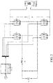
- Figs. 1 to 3 show a connecting manner of a vehicle-mounted charger of an electric vehicle according to an embodiment of the present invention.
- the vehicle-mounted charger of an electric vehicle according to embodiments of the present invention includes an H bridge.
- the H bridge includes a first switch tube T1, a second switch tube T2, a third switch tube T3 and a fourth switch tube T4.
- first inductor L1 includes a first inductor L1 and a second inductor L2, in which a first end of the first inductor L1 is connected to one end of a load or an anode end of an alternating current power grid AC, and a first end of the second inductor L2 is connected to the other end of the load or a cathode end of the alternating current power grid AC, and a second end of the first inductor L1 and a second end of the second inductor L2 are connected to the H bridge.
- the vehicle-mounted charger of an electric vehicle as shown in Fig.
- the vehicle-mounted charger of an electric vehicle as shown in Fig. 3 merely includes an inductor, for example, the first inductor LI, in which a first end of the first inductor L1 is connected to the other end of the load or a cathode end of the alternating current power grid AC, and a second end of the first inductor L1 is connected to the H bridge.
- Fig. 4 is a flow chart of a method for controlling a vehicle-mounted charger of an electric vehicle according to an embodiment of the present invention. As shown in Fig. 4 , the method for controlling a vehicle-mounted charger of an electric vehicle in an embodiment of the present invention includes the following.
- a first total discharging time TC for controlling the H bridge in a first manner and a second total discharging time TD for controlling the H bridge in a second manner are obtained, when the power battery discharges via the vehicle-mounted charger.
- the H bridge is controlled in the first manner A, and when an outward discharging transient voltage value of the vehicle-mounted charger is smaller than 0, the first switch tube T1 is controlled to be ON, the second switch tube T2 is controlled to be OFF, and the third switch tube T3 and the fourth switch tube T4 are controlled to be ON and OFF complementarily and alternately.
- the PWM waveform of the third switch tube T3 and the PWM waveform of the fourth switch tube T4 are controlled to be complementary with each other, and a duty ratio of the PWM waveform of the third switch tube T3 is controlled from large to small and then to large, and a duty ratio of the PWM waveform of the fourth switch tube T4 is controlled from small to large and then to small; when the outward discharging transient voltage value of the vehicle-mounted charger is larger than 0, the third switch tube T3 is controlled to be ON, the fourth switch tube T4 is controlled to be OFF, and the first switch tube T1 and the second switch tube T2 are controlled to be ON and OFF complementarily and alternately.
- the PWM waveform of the first switch tube T1 and the PWM waveform of the second switch tube T2 are controlled to be complementary with each other, and a duty ratio of the PWM waveform of the first switch tube T1 is controlled from large to small and then to large, and a duty ratio of the PWM waveform of the second switch tube T2 is controlled from small to large and then to small.
- the H bridge is controlled in the second manner B, and when an outward discharging transient voltage value of the vehicle-mounted charger is larger than 0, the second switch tube T2 is controlled to be ON, the first switch tube T1 is controlled to be OFF, and the third switch tube T3 and the fourth switch tube T4 are controlled to be ON and OFF complementarily and alternately.
- the PWM waveform of the third switch tube T3 and the PWM waveform of the fourth switch tube T4 are controlled to be complementary with each other, and a duty ratio of the PWM waveform of the third switch tube T3 is controlled from small to large and then to small, and a duty ratio of the PWM waveform of the fourth switch tube T4 is controlled from large to small and then to large; when the outward discharging transient voltage value of the
- the fourth switch tube T4 is controlled to be ON
- the third switch tube T3 is controlled to be OFF
- the first switch tube T1 and the second switch tube T2 are controlled to be ON and OFF complementarily and alternately.
- the PWM waveform of the first switch tube T1 and the PWM waveform of the second switch tube T2 are controlled to be complementary with each other, and a duty ratio of the PWM waveform of the first switch tube T1 is controlled from small to large and then to small, and a duty ratio of the PWM waveform of the second switch tube T2 is controlled from large to small and then to large.
- a first discharging predetermined time Tm for controlling the H bridge in the first manner and a second discharging predetermined time Tn for controlling the H bridge in the second manner are obtained.
- a manner for controlling the H bridge is selected according to a relation between the first total discharging time TC and the second total discharging time TD.
- step S4 an alternate control on the H bridge in the first manner or the second manner is performed according to the first discharging predetermined time Tm and the second discharging predetermined time Tn, so as to perform the temperature balanced control over the first switch tube, the second switch tube, the third switch tube and the fourth switch tube.
- the first discharging predetermined time Tm and the second discharging predetermined time Tn are preset for each discharging cycle of a discharging process of the power battery.
- the H bridge is only controlled by using the second manner B, when the outward discharging transient voltage value is larger than 0, the first switch tube T1 is kept OFF always, the second switch tube T2 is kept ON always, and the third switch tube T3 and fourth switch tube T4 are ON and OFF alternately and complementarily, and the inductor in the vehicle-mounted charger is charged when the fourth switch tube T4 is OFF and the third switch tube T3 is ON, and discharges when the fourth switch tube T4 is ON and the third switch tube T3 is OFF; when the outward discharging transient voltage value is smaller than 0, the fourth switch tube T4 is kept ON always, the third switch tube T3 is kept OFF always, and the first switch tube T1 and second switch tube T2 are ON and OFF alternately and complementarily, and the inductor in the vehicle-mounted charger is charged when the second switch tube T2 is OFF and the first switch tube T1 is ON, and discharges when
- the inductor Since the inductor is charged when the first tube T1 and the third tube T3 are ON, the first switch tube T1 and the third switch tube T3 are OFF with current, and hard switching is performed, therefore, the first switch tube T1 and the third switch tube T3 are overheated.
- the H bridge when the H bridge is controlled by using the first manner A to enable to discharge from the power battery via the vehicle-mounted charger, the time that the H bridge is controlled in the first manner A is recorded, thus the first total discharging time TC of controlling the H bridge in the first manner A is obtained, and then is stored; when the H bridge is controlled by using the second manner B enable to discharge from the power battery via the vehicle-mounted charger, the time that the H bridge is controlled in the second manner B is recorded, thus the second total discharging time TD of controlling the H bridge in the second manner B is obtained, and then is stored.
- the relation between the first total discharging time TC and the second total discharging time TD is determined.
- the manner of controlling the H bridge is selected when the power battery discharges via the vehicle-mounted charger according to the relation between the first total discharging time TC and the second total discharging time TD, thereby realizing the temperature balanced control over the first switch tube, the second switch tube, the third switch tube and the fourth switch tube.
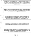
- Fig. 5 is a flow chart of a method for controlling a vehicle-mounted charger of an electric vehicle according to another embodiment of the present invention.
- step S3 further includes followings.
- the manner from the first manner and the second manner for controlling the H bridge is selected according to the relation between the first total discharging time TC and the second total discharging time TD.
- the H bridge is controlled in the selected manner, until the first total discharging time TC is equal to the second total discharging time TD.
- selecting the manner of controlling the H bridge according to the relation between the first total discharging time TC and the second total discharging time TD includes: if the first total discharging time TC is larger than the second total discharging time TD, the second manner B for controlling the H bridge is selected when the power battery discharges via the vehicle-mounted charger, and then the H bridge is controlled in the second manner B until the first total discharging time TC is equal to the second total discharging time TD, and then the alternate control is performed on the H bridge according to the first discharging predetermined time Tm and the second discharging predetermined time Tn; if the second total discharging time TD is larger than the first total discharging time TC, the first manner A for controlling the H bridge is selected when the power battery discharges via the vehicle-mounted charger, and then the H bridge is controlled in the first manner A until the first total discharging time TC is equal to the second total discharging time TD, and then the alternate control is performed on the H bridge
- the alternate control on the H bridge is performed according to the first discharging predetermined time Tm and the second discharging predetermined time Tn when the power battery discharges via the vehicle-mounted charger includes: when a time of controlling the H bridge in the first manner A reaches the first discharging predetermined time Tm, the H bridge in the second manner B is controlled till a time of controlling the H bridge in the second manner B reaches the second discharging predetermined time Tn; or when a time of controlling the H bridge in the second manner B reaches the second discharging predetermined time Tn, the H bridge in the first manner A is controlled till a time of controlling the H bridge in the first manner A reaches the first discharging predetermined time Tm.
- the first total discharging time TC that the H bridge is controlled in the first manner A as well as the second total discharging time TD that the H bridge is controlled in the second manner B are obtained from a storage region.
- the first discharging predetermined time Tm and the second discharging predetermined time Tn are preset. Then the relation between the first total discharging time TC and the second total discharging time TD is determined, the first manner A for controlling the H bridge firstly or the second manner B for controlling the H bridge firstly is determined according the relation.
- the first total discharging time TC and the second total discharging time TD are obtained from the storage region, an aim to determine the relation between the first total discharging time TC and the second total discharging time TD is to determine the selected manner for controlling the H bridge firstly when the power battery discharges via the vehicle-mounted charger.
- the H bridge is controlled by selecting the second manner B because the obtained time TC is greater than the obtained time TD, so as to enable to discharge from the power battery via the vehicle-mounted charger.
- the H bridge is switched to be controlled by using the first manner A, so as to discharge from the power battery via the vehicle-mounted charger till the time that the H bridge is controlled in the first manner A reaches Tm, then the H bridge is switched to be controlled by using the second manner B till the time that the H bridge is controlled in the second manner B reaches Tn, thereby finishing one discharging cycle (i.e., the time of one discharging cycle equals to Tm+Tn); then the H bridge is switched to be controlled by using the first manner A to enable to discharge from the power battery via the vehicle-mounted charger till the time that the H bridge is controlled by using the first manner A reaches Tm, then the H bridge is switched to be controlled by using the second manner B to enable to discharge from the power battery via the vehicle-mounted charger till the time that the H bridge is controlled by using the second manner B reaches Tn, ..., and the like, thereby realizing the alternative control over the H bridge, and further performing the temperature balanced control over the first switch tube, the second switch tube, the third switch
- the H bridge is controlled by selecting the first manner A because the obtained time TD is greater than the obtained time TC, so as to enable to discharge from the power battery via the vehicle-mounted charger.
- the H bridge is switched to be controlled by using the second manner B, so as to discharge from the power battery via the vehicle-mounted charger till the time that the H bridge is controlled by the second manner B reaches Tn, then the H bridge is switched to be controlled by using the first manner A till the time that the H bridge is controlled by the first manner A reaches Tm, thereby finishing one discharging cycle (i.e., the time of one discharging cycle equals to Tm+Tn); then the H bridge is switched to be controlled by using the second manner B to enable to discharge from the power battery via the vehicle-mounted charger till the time that the H bridge is controlled by using the second manner B reaches Tn, then the H bridge is switched to be controlled by using the first manner A to enable to discharge from the power battery via the vehicle-mounted charger till the time that the H bridge is controlled by using the first manner A reaches Tm, ..., and the like, thereby realizing the alternative control over the H bridge, and further performing the temperature balanced control over the first switch tube, the second switch tube, the third switch
- the H bridge can be controlled by selecting the first manner A to enable to discharge from the power battery via the vehicle-mounted charger till the time that the H bridge is controlled in the first manner A reaches Tm, then the H bridge is switched to be controlled by using the second manner B till the time that the H bridge is controlled in the second manner B reaches Tn, thereby finishing one discharging cycle (i.e., the time of one discharging cycle equals to Tm+Tn); then the H bridge is switched to be controlled by using the first manner A to enable to discharge from the power battery via the vehicle-mounted charger till the time that the H bridge is controlled by using the first manner A reaches Tm, then the H bridge is switched to be controlled by using the second manner B to enable to discharge from the power battery via the vehicle-mounted charger till the time that the H bridge is controlled by using the second manner B reaches Tn, ..., and the like, thereby realizing the alternative control
- the H bridge can be controlled by selecting the second manner B to enable to discharge from the power battery via the vehicle-mounted charger till the time that the H bridge is controlled by the second manner B reaches Tn, then the H bridge is switched to be controlled by using the first manner A till the time that the H bridge is controlled by the first manner A reaches Tm, thereby finishing one discharging cycle (i.e., the time of one discharging cycle equals to Tm+Tn); then the H bridge is switched to be controlled by using the second manner B to enable to discharge from the power battery via the vehicle-mounted charger till the time that the H bridge is controlled by using the second manner B reaches Tn, then the H bridge is switched to be controlled by using the first manner A to enable to discharge from the power battery via the vehicle-mounted charger till the time that the H bridge is controlled by using the first manner A reaches Tm, ..., and the like, thereby realizing the alternative control over the
- the H bridge is controlled to discharge from the power battery according to a fixed manner, i.e., the first or second manner, the total discharging time is recorded when the manner is switched, for example, when the H bridge is firstly controlled by using the first manner, the first total discharging time is recorded in this manner switching, and then the first total discharging time is obtained from the storage region when this discharging starts plus the discharging time recorded in the discharging cycle of this time.
- the first discharging predetermined time Tm that the H bridge is controlled in the first manner A is equal to the second discharging predetermined time Tn that the H bridge is controlled in the second manner B, thereby precisely controlling heating of the first switch tube T1, the second switch tube T2, the third switch tube T3 and the fourth switch tube T4 to be relatively balanced.
- the method for controlling a vehicle-mounted charger of an electric vehicle includes the following steps.
- a discharging wave is opened, i.e., when the power battery discharges via the vehicle-mounted charger, a control waveform needs to be output to control the switch tubes in the H bridge.
- a first total discharging time TC in the first manner A and a second total discharging time TD in the second manner B are obtained.
- a first discharging predetermined time Tm and a second discharging predetermined time Tn are set.
- step S504 it is judged whether the first total discharging time TC is larger than the second total discharging time TD, step S505 is executed if yes, and step S506 is executed if not.
- step S505 the second manner B is selected to control the H bridge till the first total discharging time TC is equal to the second total discharging time TD, then step S508 is executed.
- step S506 it is judged whether the first total discharging time TC is smaller than the second total discharging time TD, step S507 is executed if yes and step S508 or step S509 is executed if not.
- step S507 the first manner A is selected to control the H bridge till the first total discharging time TC is equal to the second total discharging time TD, then step S509 is executed.
- step S508 the first manner A is adopted to control the H bridge to enable to discharge from the power battery via the vehicle-mounted charger, then step S510 is executed.
- step S509 the second manner B is adopted to control the H bridge to enable to discharge from the power battery via the vehicle-mounted charger, then step S511 is executed.
- step S510 it is judged whether the time that the H bridge is controlled by using the first manner A reaches Tm, step S512 is executed if yes, and it is returned to step S508 if not.
- step S513 it is judged whether the time that the H bridge is controlled by using the second manner B reaches Tn, step S513 is executed if yes, and it is returned to step S509 if not.
- step S512 it is judged whether the discharging of this time ends during the discharging process, step S514 if yes and it is returned to continue to judge in step 509 if not.
- step S514 it is judged whether the discharging of this time ends during the discharging process, step S514 if yes and it is returned to continue to judge in step 508 if not.
- the heating of the first switch tube, the second switch tube, the third switch tube and the fourth switch tube is enabled to be relative balanced, and the service life of the vehicle-mounted charger is prolonged.
- the first total discharging time for controlling the H bridge in the first manner and the second total discharging time for controlling the H bridge in the second manner are obtained, and the first discharging predetermined time for controlling the H bridge in the first manner and the second discharging predetermined time for controlling the H bridge in the second manner are also obtained; and the manner from the first manner and the second manner for controlling the H bridge is selected according to the relation between the first total discharging time and the second total discharging time when the power battery discharges via the vehicle-mounted charger; finally, the alternate control on the H bridge in the first manner or the second manner is performed according to the first discharging predetermined time and the second discharging predetermined time, so as to perform the temperature balanced control over the first switch tube, the second switch tube, the third switch tube and the fourth switch tube, such that the heating of each switch tube is relatively balanced, the service life of the switch tubes in the
- a vehicle-mounted charger includes an H bridge and a controller such as an MCU (Micro Control Unit).
- the H bridge includes a first switch tube T1, a second switch tube T2, a third switch tube T3 and a fourth switch tube T4.
- the controller is configured to obtain a first total discharging time TC for controlling the H bridge in a first manner, and a second total discharging time TD for controlling the H bridge in a second manner when the power battery discharges via the vehicle-mounted charger; to obtain a first discharging predetermined time Tm for controlling the H bridge in the first manner and a second discharging predetermined time Tn for controlling the H bridge in the second manner; to select a manner for controlling the H bridge according to a relation between the first total discharging time TC and the second total discharging time TD; and to perform an alternate control on the H bridge in the first manner or the second manner according to the first discharging predetermined time Tm and the second discharging predetermined time Tn to perform temperature balanced control over the first switch tube, the second switch tube, the third switch tube and the fourth switch tube, in which the first discharging predetermined time Tm and the second discharging predetermined time Tn are preset for each discharging cycle of a discharging process of the power battery.
- the controller is configured to control the H bridge in the first manner A, such that when the power battery discharges via the vehicle-mounted charger, the time that the H bridge is controlled in the first manner A is recorded, thus the first total discharging time TC of controlling the H bridge in the first manner A is obtained, and then is stored;
- the controller is configured to control the H bridge in the second manner B, such that when the power battery discharges via the vehicle-mounted charger, the time that the H bridge is controlled in the second manner B is recorded, thus the second total discharging time TD of controlling the H bridge in the second manner B is obtained, and then is stored.
- the controller determines the relation between the first total discharging time TC and the second total discharging time TD every time.
- the manner of controlling the H bridge is selected according to the relation between the first total discharging time TC and the second total discharging time TD when the power battery discharges via the vehicle-mounted charger, thereby realizing the temperature balanced control over the first switch tube, the second switch tube, the third switch tube and the fourth switch tube.
- the controller is configured to select the manner from the first manner and the second manner for controlling the H bridge according to the relation between the first total discharging time TC and the second total discharging time TD; and control the H bridge in the selected manner, until the first total discharging time TC is equal to the second total discharging time TD.
- the controller is configured to select the manner of controlling the H bridge according to the relation between the first total discharging time TC and the second total discharging time TD by steps of: if the first total discharging time TC is larger than the second total discharging time TD, the second manner B for controlling the H bridge is selected when the power battery discharges via the vehicle-mounted charger, and then the H bridge is controlled in the second manner B until the first total discharging time TC is equal to the second total discharging time TD, and then the alternate control is performed on the H bridge according to the first discharging predetermined time Tm and the second discharging predetermined time Tn; if the second total discharging time TD is larger than the first total discharging time TC, the first manner A for controlling the H bridge is selected when the power battery discharges via the vehicle-mounted charger, and then the H bridge is controlled in the first manner A until the first total discharging time TC is equal to the second total discharging time TD, and then the alternate
- the controller is configured to perform the alternate control on the H bridge according to the first discharging predetermined time Tm and the second discharging predetermined time Tn when the power battery discharges via the vehicle-mounted charger by steps of: when a time of controlling the H bridge in the first manner A reaches the first discharging predetermined time Tm, controlling the H bridge in the second manner B till a time of controlling the H bridge in the second manner B reaches the second discharging predetermined time Tn; or when a time of controlling the H bridge in the second manner B reaches the second discharging predetermined time Tn, controlling the H bridge in the first manner A till a time of controlling the H bridge in the first manner A reaches the first discharging predetermined time Tm.
- the first total discharging time TC that the H bridge is controlled in the first manner A as well as the second total discharging time TD that the H bridge is controlled in the second manner B are obtained from a storage region.
- the first discharging predetermined time Tm and the second discharging predetermined time Tn are preset. Then the relation between the first total discharging time TC and the second total discharging time TD is determined, the first manner A for controlling the H bridge firstly or the second manner B for controlling the H bridge firstly is determined according the relation.
- the first total discharging time TC and the second total discharging time TD are obtained from the storage region, an aim to determine the relation between the first total discharging time TC and the second total discharging time TD is to determine the selected manner for controlling the H bridge firstly when the power battery discharges via the vehicle-mounted charger.
- the H bridge is controlled by selecting the second manner B because the obtained time TC is greater than the obtained time TD, so as to enable to discharge from the power battery via the vehicle-mounted charger.
- the H bridge is switched to be controlled by using the first manner A, so as to discharge from the power battery via the vehicle-mounted charger till the time that the H bridge is controlled in the first manner A reaches Tm, then the H bridge is switched to be controlled by using the second manner B till the time that the H bridge is controlled in the second manner B reaches Tn, thereby finishing one discharging cycle (i.e., the time of one discharging cycle equals to Tm+Tn); then the H bridge is switched to be controlled by using the first manner A to enable to discharge from the power battery via the vehicle-mounted charger till the time that the H bridge is controlled by using the first manner A reaches Tm, then the H bridge is switched to be controlled by using the second manner B to enable to discharge from the power battery via the vehicle-mounted charger till the time that the H bridge is controlled by using the second manner B reaches Tn, ..., and the like, thereby realizing the alternative control over the H bridge, and further performing the temperature balanced control over the first switch tube, the second switch tube, the third switch
- the H bridge is controlled by selecting the first manner A because the obtained time TD is greater than the obtained time TC, so as to enable to discharge from the power battery via the vehicle-mounted charger.
- the H bridge is switched to be controlled by using the second manner B, so as to discharge from the power battery via the vehicle-mounted charger till the time that the H bridge is controlled by the second manner B reaches Tn, then the H bridge is switched to be controlled by using the first manner A till the time that the H bridge is controlled by the first manner A reaches Tm, thereby finishing one discharging cycle (i.e., the time of one discharging cycle equals to Tm+Tn); then the H bridge is switched to be controlled by using the second manner B to enable to discharge from the power battery via the vehicle-mounted charger till the time that the H bridge is controlled by using the second manner B reaches Tn, then the H bridge is switched to be controlled by using the first manner A to enable to discharge from the power battery via the vehicle-mounted charger till the time that the H bridge is controlled by using the first manner A reaches Tm, ..., and the like, thereby realizing the alternative control over the H bridge, and further performing the temperature balanced control over the first switch tube, the second switch tube, the third switch
- the H bridge can be controlled by selecting the first manner A to enable to discharge from the power battery via the vehicle-mounted charger till the time that the H bridge is controlled in the first manner A reaches Tm, then the H bridge is switched to be controlled by using the second manner B till the time that the H bridge is controlled in the second manner B reaches Tn, thereby finishing one discharging cycle (i.e., the time of one discharging cycle equals to Tm+Tn); then the H bridge is switched to be controlled by using the first manner A to enable to discharge from the power battery via the vehicle-mounted charger till the time that the H bridge is controlled by using the first manner A reaches Tm, then the H bridge is switched to be controlled by using the second manner B to enable to discharge from the power battery via the vehicle-mounted charger till the time that the H bridge is controlled by using the second manner B reaches Tn, ..., and the like, thereby realizing the alternative control
- the H bridge can be controlled by selecting the second manner B to enable to discharge from the power battery via the vehicle-mounted charger till the time that the H bridge is controlled by the second manner B reaches Tn, then the H bridge is switched to be controlled by using the first manner A till the time that the H bridge is controlled by the first manner A reaches Tm, thereby finishing one discharging cycle (i.e., the time of one discharging cycle equals to Tm+Tn); then the H bridge is switched to be controlled by using the second manner B to enable to discharge from the power battery via the vehicle-mounted charger till the time that the H bridge is controlled by using the second manner B reaches Tn, then the H bridge is switched to be controlled by using the first manner A to enable to discharge from the power battery via the vehicle-mounted charger till the time that the H bridge is controlled by using the first manner A reaches Tm, ..., and the like, thereby realizing the alternative control over the
- the first discharging predetermined time Tm that the H bridge is controlled in the first manner A equals to the second discharging predetermined time Tn that the H bridge is controlled in the second manner B.
- the controller is configured to control the H bridge in the first manner A to discharge from the power battery, and when an outward discharging transient voltage value of the vehicle-mounted charger is smaller than 0, the first switch tube T1 is controlled to be ON, the second switch tube T2 is controlled to be OFF, and the third switch tube T3 and the fourth switch tube T4 are controlled to be ON and OFF complementarily and alternately.
- the PWM waveform of the third switch tube T3 and the PWM waveform of the fourth switch tube T4 are controlled to be complementary with each other, and a duty ratio of the PWM waveform of the third switch tube T3 is controlled from large to small and then to large, and a duty ratio of the PWM waveform of the fourth switch tube T4 is controlled from small to large and then to small; when the outward discharging transient voltage value of the vehicle-mounted charger is larger than 0, the third switch tube T3 is controlled to be ON, the fourth switch tube T4 is controlled to be OFF, and the first switch tube T1 and the second switch tube T2 are controlled to be ON and OFF complementarily and alternately.
- the PWM waveform of the first switch tube T1 and the PWM waveform of the second switch tube T2 are controlled to be complementary with each other, and a duty ratio of the PWM waveform of the first switch tube T1 is controlled from large to small and then to large, and a duty ratio of the PWM waveform of the second switch tube T2 is controlled from small to large and then to small.
- the controller when the controller is configured to control the H bridge in the second manner B, and when an outward discharging transient voltage value of the vehicle-mounted charger is larger than 0, the second switch tube T2 is controlled to be ON, the first switch tube T1 is controlled to be OFF, and the third switch tube T3 and the fourt switch tube T4 are controlled to be ON and OFF complementarily and alternately.
- the PWM waveform of the third switch tube T3 and the PWM waveform of the fourth switch tube T4 are controlled to be complementary with each other, and a duty ratio of the PWM waveform of the third switch tube T3 is controlled from small to large and then to small, and a duty ratio of the PWM waveform of the fourth switch tube T4 is controlled from large to small and then to large; when the outward discharging transient voltage value of the vehicle-mounted charger is smaller than 0, the fourth switch tube T4 is controlled to be ON, the third switch tube T3 is controlled to be OFF, and the first switch tube T1 and the second switch tube T2 are controlled to be ON and OFF complementarily and alternately.
- the PWM waveform of the first switch tube T1 and the PWM waveform of the second switch tube T2 are controlled to be complementary with each other, and a duty ratio of the PWM waveform of the first switch tube T1 is controlled from small to large and then to small, and a duty ratio of the PWM waveform of the second switch tube T2 is controlled from large to small and then to large.
- the first switch tube T1, the second switch tube T2, the third switch tube T3 and the fourth switch tube T4 are all IGBTs (Insulated Gate Bipolar Transistors), certainly, in other embodiments of the present invention, the first switch tube T1, the second switch tube T2, the third switch tube T3 and the fourth switch tube T4 can also be MOSs (Metal Oxide Semiconductors).
- the first discharging predetermined time Tm and the second discharging predetermined time Tn are preset for each discharging cycle of a discharging process of the power battery, so as to perform the temperature balanced control over the first switch tube, the second switch tube, the third switch tube and the fourth switch tube.
- the controller when the power battery discharges via the vehicle-mounted charger every time, the controller is configured to obtain the first total discharging time for controlling the H bridge in the first manner and the second total discharging time for controlling the H bridge in the second manner, to obtain the first discharging predetermined time for controlling the H bridge in the first manner and the second discharging predetermined time for controlling the H bridge in the second manner; and to select the manner from the first manner and the second manner for controlling the H bridge according to the relation between the first total discharging time and the second total discharging time, finally, to perform the alternate control on the H bridge in the first manner or the second manner according to the first discharging predetermined time and the second discharging predetermined time, so as to perform temperature balanced control over the first switch tube, the second switch tube, the third switch tube and the fourth switch tube, such that the heating of each switch tube is relatively balanced, the service life of the switch tubes in the H bridge is prolonged, and thus the service time is prolonged.
- embodiments of the present invention also provide an electric vehicle, including the above vehicle-mounted charger of an electric vehicle.
- the temperature balanced control over the first switch tube, the second switch tube, the third switch tube and the fourth switch tube in the H bridge can be realized, such that the heating of each switch tube is balanced, the service life of the switch tubes in the H bridge is prolonged, and thus the service time of the vehicle-mounted charger is prolonged.
- first and second merely aim to describe rather than being understood as indication or implication of relative importance or impliedly indicating a number of the indicated technical features. Therefore, the characteristics defined by “first” and “second” can clearly or impliedly comprise at least one such characteristic. In the description of the present invention, “more” means at least two, for example, two, three, etc., unless otherwise clearly specifically defined.
- the terms “mounted”, “jointed”, “connected”, “fixed”, etc. should be generalized understood, for example, the “connected” can be fixedly connected, or detachably connected, or integrated, can be mechanically connected or electrically connected, can also be directly connected or connected by an intermediate medium, and can also be internally communicated of two elements, or interacted of two elements, unless otherwise clearly defined.
- the terms “connected” can be fixedly connected, or detachably connected, or integrated, can be mechanically connected or electrically connected, can also be directly connected or connected by an intermediate medium, and can also be internally communicated of two elements, or interacted of two elements, unless otherwise clearly defined.
- the case that a first characteristic is "on” or “under” a second characteristic can be the case that the first characteristic and the second characteristic are in direct contact, or in indirect contact by an intermediate medium.
- the case that the first characteristic is "on”, “above” and “over” the second characteristic can be the case that the first characteristic is right or obliquely above the second characteristic, or only represents that the horizontal height of the first characteristic is higher than that of the second characteristic.
- the case that the first characteristic is "under”, “below” and “beneath” the second characteristic can be the case that the first characteristic is right or obliquely below the second characteristic, or only represents that the horizontal height of the first characteristic is lower than that of the second characteristic.
- the description of the reference terms “one embodiment”, “some embodiments”, “examples”, “specific examples” or “some examples” refers to the fact that the specific characteristic, structure, material or feature described in combination with the embodiment or example is contained in the at least one embodiment or example of the present invention.
- the schematic expression of the above terms unnecessarily aims at the same embodiment or example.
- the described specific characteristic, structure, material or feature can be combined in a proper manner in any one or more embodiments or examples.
- those skilled in the art can integrate or combine different embodiments or examples or the characteristics of different embodiments or examples described in the present specification.
Description
- The present invention relates to the technical field of electric vehicles, in particular to a method for controlling a vehicle-mounted charger of an electric vehicle, a vehicle-mounted charger of an electric vehicle, and an electric vehicle.
- Along with the commercialization progress of electric vehicles, a vehicle-mounted charger of the electric vehicles has become one of important components in the electric vehicles.
- There are many methods for discharging outwards from the whole vehicle via the vehicle-mounted charger. A monophase H bridge off-grid conversion control method is mostly adopted in related arts, which includes a dual-polarity control method and a mono-polarity control method.
- However, when the dual-polarity control method is adopted, four switch tubes in an H bridge are all in a high frequency ON/OFF state, resulting in higher switching loss and larger heat loss; when the mono-polarity control method is adopted, although the heat loss of the switch tubes that is generated when the dual-polarity control method is adopted can be solved to some extent, the four switch tubes in the H bridge are controlled according to a fixing manner during a charging process or a discharging process of the whole vehicle, some switch tubes in the H bridge need to be switched off with current, so that the overheat problem of the switch tubes switched off with current is not effectively solved.
- Therefore, no matter the dual-polarity control method or the mono-polarity control method is adopted, the heating problem of the switch tubes in the H bridge cannot be effectively solved, and the service life of the switch tubes is affected.
-
CN 104 600 998 A andEP 2 731 252 A1 each disclose a method for controlling a vehicle-mounted charger of an electric vehicle, wherein the vehicle-mounted charger comprises an H bridge, the H bridge comprises a first switch tube, a second switch tube, a third switch tube, and a fourth switch tube, and the method comprises: performing an alternate control on the H bridge in a first manner or a second manner to perform temperature balanced control over the first switch tube, the second switch tube, the third switch tube, and the fourth switch tube. - The present invention aims to solve at least one of the technical problems in the related art to some extent. For this purpose, a first objective of the present invention is to provide a method for controlling a vehicle-mountable charger of an electric vehicle, which is capable of enabling heating of a first switch tube, a second switch tube, a third switch tube and a fourth switch tube in an H bridge to be relatively balanced, and improving a service life of the switch tubes in the H bridge.
- A second objective of the present invention is to provide a vehicle-mountable charger of an electric vehicle. A third objective of the present invention is to provide an electric vehicle.
- For the above purpose, in one aspect of embodiments of the present invention, there is provided a method for controlling a vehicle-mountable charger of an electric vehicle according to
claim 1. According to the method for controlling a vehicle-mountable charger of an electric vehicle in embodiments of the present invention, when the power battery discharges via the vehicle-mountable charger every time, the first total discharging time for controlling the H bridge in the first manner and the second total discharging time for controlling the H bridge in the second manner are obtained, and the first discharging predetermined time for controlling the H bridge in the first manner and the second discharging predetermined time for controlling the H bridge in the second manner are also obtained; and the manner for controlling the H bridge is selected according to the relation between the first total discharging time and the second total discharging time; finally, the alternate control on the H bridge in the first manner or the second manner is performed according to the first discharging predetermined time and the second discharging predetermined time, so as to perform the temperature balanced control over the first switch tube, the second switch tube, the third switch tube and the fourth switch tube, such that the heating of each switch tube is relatively balanced, the service life of the switch tubes in the H bridge is prolonged, and thus the service time is prolonged. - For the above purpose, in another aspect of embodiments of the present invention, there is provided a vehicle-mountable charger of an electric vehicle according to
claim 4. According to the vehicle-mountable charger of an electric vehicle in embodiments of the present invention, when the power battery discharges via the vehicle-mountable charger every time, the controller is configured to obtain the first total discharging time for controlling the H bridge in the first manner and the second total discharging time for controlling the H bridge in the second manner, to obtain the first discharging predetermined time for controlling the H bridge in the first manner and the second discharging predetermined time for controlling the H bridge in the second manner; and to select the manner for controlling the H bridge according to the relation between the first total discharging time and the second total discharging time, finally, to perform the alternate control on the H bridge in the first manner or the second manner according to the first discharging predetermined time and the second discharging predetermined time, so as to perform the temperature balanced control over the first switch tube, the second switch tube, the third switch tube and the fourth switch tube, such that the heating of each switch tube is relatively balanced, the service life of the switch tubes in the H bridge is prolonged, and thus the service time is prolonged. - In addition, an embodiment of the present invention also provides an electric vehicle, including the vehicle-mountable charger of an electric vehicle.
- According to the electric vehicle in embodiments of the present invention, when the power battery discharges via the vehicle-mountable charger, the temperature balanced control over the first switch tube, the second switch tube, the third switch tube and the fourth switch tube in the H bridge can be realized, such that the heating of each switch tube is balanced, the service life of the switch tubes in the H bridge is prolonged, and thus the service time of the vehicle-mountable charger is prolonged.
-
-
Fig. 1 is a circuit schematic diagram of a vehicle-mounted charger of an electric vehicle of an embodiment of the present invention; -
Fig. 2 is a circuit schematic diagram of a vehicle-mounted charger of an electric vehicle of another embodiment of the present invention; -
Fig. 3 is a circuit schematic diagram of a vehicle-mounted charger of an electric vehicle of still another embodiment of the present invention; -
Fig. 4 is a flow chart of a method for controlling a vehicle-mounted charger of an electric vehicle of an embodiment of the present invention; -
Fig. 5 is a flow chart of a method for controlling a vehicle-mounted charger of an electric vehicle of another embodiment of the present invention; -
Fig. 6 is a schematic diagram of a control waveform of four switch tubes when an H bridge is controlled by using a first manner to enable a power battery to outwards discharge according to an embodiment of the present invention; -
Fig. 7 is a schematic diagram of a control waveform of four switch tubes when an H bridge is controlled by using a second manner to enable a power battery to outwards discharge according to an embodiment of the present invention; and -
Fig. 8 is a control flow chart when a power battery discharges via a vehicle-mounted charger according to a specific embodiment of the present invention. - The embodiments of the present invention are described in detail, examples of the embodiments are shown in the drawings, wherein, the same or similar numbers represent same or similar elements or elements having the same or similar functions from beginning to end. The embodiments described with reference to the drawings are exemplary, and aim to explain the present invention rather than understood as a limitation to the present invention.
- The method for controlling a vehicle-mounted charger of an electric vehicle, a vehicle-mounted charger of an electric vehicle, and an electric vehicle with the vehicle-mounted charger, provided in embodiments of the present invention, are described with reference to the drawings as follows.
-
Figs. 1 to 3 show a connecting manner of a vehicle-mounted charger of an electric vehicle according to an embodiment of the present invention. As shown inFigs. 1 to 3 , the vehicle-mounted charger of an electric vehicle according to embodiments of the present invention includes an H bridge. The H bridge includes a first switch tube T1, a second switch tube T2, a third switch tube T3 and a fourth switch tube T4. The vehicle-mounted charger of an electric vehicle as shown inFig. 1 includes a first inductor L1 and a second inductor L2, in which a first end of the first inductor L1 is connected to one end of a load or an anode end of an alternating current power grid AC, and a first end of the second inductor L2 is connected to the other end of the load or a cathode end of the alternating current power grid AC, and a second end of the first inductor L1 and a second end of the second inductor L2 are connected to the H bridge. The vehicle-mounted charger of an electric vehicle as shown inFig. 2 merely includes an inductor, for example, the inductor LI, in which a first end of the first inductor L1 is connected to one end of a load or an anode end of an alternating current power grid AC, and a second end of the first inductor L1 is connected to the H bridge. The vehicle-mounted charger of an electric vehicle as shown inFig. 3 merely includes an inductor, for example, the first inductor LI, in which a first end of the first inductor L1 is connected to the other end of the load or a cathode end of the alternating current power grid AC, and a second end of the first inductor L1 is connected to the H bridge. -
Fig. 4 is a flow chart of a method for controlling a vehicle-mounted charger of an electric vehicle according to an embodiment of the present invention. As shown inFig. 4 , the method for controlling a vehicle-mounted charger of an electric vehicle in an embodiment of the present invention includes the following. - At step S1, a first total discharging time TC for controlling the H bridge in a first manner and a second total discharging time TD for controlling the H bridge in a second manner are obtained, when the power battery discharges via the vehicle-mounted charger.
- According to an embodiment of the present invention, as shown in
Fig. 6 , if the H bridge is controlled in the first manner A, and when an outward discharging transient voltage value of the vehicle-mounted charger is smaller than 0, the first switch tube T1 is controlled to be ON, the second switch tube T2 is controlled to be OFF, and the third switch tube T3 and the fourth switch tube T4 are controlled to be ON and OFF complementarily and alternately. When the third switch tube T3 and the fourth switch tube T4 are controlled to be ON and OFF alternately and complementarily, the PWM waveform of the third switch tube T3 and the PWM waveform of the fourth switch tube T4 are controlled to be complementary with each other, and a duty ratio of the PWM waveform of the third switch tube T3 is controlled from large to small and then to large, and a duty ratio of the PWM waveform of the fourth switch tube T4 is controlled from small to large and then to small; when the outward discharging transient voltage value of the vehicle-mounted charger is larger than 0, the third switch tube T3 is controlled to be ON, the fourth switch tube T4 is controlled to be OFF, and the first switch tube T1 and the second switch tube T2 are controlled to be ON and OFF complementarily and alternately. When the first switch tube T1 and the second switch tube T2 are controlled to be ON and OFF alternately and complementarily, the PWM waveform of the first switch tube T1 and the PWM waveform of the second switch tube T2 are controlled to be complementary with each other, and a duty ratio of the PWM waveform of the first switch tube T1 is controlled from large to small and then to large, and a duty ratio of the PWM waveform of the second switch tube T2 is controlled from small to large and then to small. - According to an embodiment of the present invention, as shown in
Fig. 7 , if the H bridge is controlled in the second manner B, and when an outward discharging transient voltage value of the vehicle-mounted charger is larger than 0, the second switch tube T2 is controlled to be ON, the first switch tube T1 is controlled to be OFF, and the third switch tube T3 and the fourth switch tube T4 are controlled to be ON and OFF complementarily and alternately. When the third switch tube T3 and the fourth switch tube T4 are controlled to be ON and OFF alternately and complementarily, the PWM waveform of the third switch tube T3 and the PWM waveform of the fourth switch tube T4 are controlled to be complementary with each other, and a duty ratio of the PWM waveform of the third switch tube T3 is controlled from small to large and then to small, and a duty ratio of the PWM waveform of the fourth switch tube T4 is controlled from large to small and then to large; when the outward discharging transient voltage value of the - vehicle-mounted charger is smaller than 0, the fourth switch tube T4 is controlled to be ON, the third switch tube T3 is controlled to be OFF, and the first switch tube T1 and the second switch tube T2 are controlled to be ON and OFF complementarily and alternately. When the first switch tube T1 and the second switch tube T2 are controlled to be ON and OFF alternately and complementarily, the PWM waveform of the first switch tube T1 and the PWM waveform of the second switch tube T2 are controlled to be complementary with each other, and a duty ratio of the PWM waveform of the first switch tube T1 is controlled from small to large and then to small, and a duty ratio of the PWM waveform of the second switch tube T2 is controlled from large to small and then to large.
- At step S2, a first discharging predetermined time Tm for controlling the H bridge in the first manner and a second discharging predetermined time Tn for controlling the H bridge in the second manner are obtained.
- At step S3, a manner for controlling the H bridge is selected according to a relation between the first total discharging time TC and the second total discharging time TD.
- At step S4, an alternate control on the H bridge in the first manner or the second manner is performed according to the first discharging predetermined time Tm and the second discharging predetermined time Tn, so as to perform the temperature balanced control over the first switch tube, the second switch tube, the third switch tube and the fourth switch tube.
- In an embodiment of the present invention, the first discharging predetermined time Tm and the second discharging predetermined time Tn are preset for each discharging cycle of a discharging process of the power battery.
- In the process of discharging from the power battery via the vehicle-mounted charger, if the H bridge is only controlled by using the first manner A, when the outward discharging transient voltage value is smaller than 0, the first switch tube T1 is kept ON always, the second switch tube T2 is kept OFF always, and the third switch tube T3 and fourth switch tube T4 are ON and OFF alternately and complementarily, and the inductor in the vehicle-mounted charger is charged when the third switch tube T3 is OFF and the fourth switch tube T4 is ON, and discharges when the third switch tube T3 is ON and the fourth switch tube T4 is OFF; when the outward discharging transient voltage value is larger than 0, the third switch tube T3 is kept ON always, the fourth switch tube T4 is kept OFF always, and the first switch tube T1 and second switch tube T2 are ON and OFF alternately and complementarily, and the inductor in the vehicle-mounted charger is charged when the first switch tube T1 is OFF and the second switch tube T2 is ON, and discharges when the first switch tube T1 is ON and the second switch tube T2 is OFF. Since the inductor is charged when the second switch tube T2 and the fourth switch tube T3 are ON, the second switch tube T2 and the fourth switch tube T4 are OFF with current, and hard switching is performed, therefore, the second switch tube T2 and the fourth switch tube T4 are overheated.
- Similarly, in the process of discharging from the power battery via the vehicle-mounted charger, if the H bridge is only controlled by using the second manner B, when the outward discharging transient voltage value is larger than 0, the first switch tube T1 is kept OFF always, the second switch tube T2 is kept ON always, and the third switch tube T3 and fourth switch tube T4 are ON and OFF alternately and complementarily, and the inductor in the vehicle-mounted charger is charged when the fourth switch tube T4 is OFF and the third switch tube T3 is ON, and discharges when the fourth switch tube T4 is ON and the third switch tube T3 is OFF; when the outward discharging transient voltage value is smaller than 0, the fourth switch tube T4 is kept ON always, the third switch tube T3 is kept OFF always, and the first switch tube T1 and second switch tube T2 are ON and OFF alternately and complementarily, and the inductor in the vehicle-mounted charger is charged when the second switch tube T2 is OFF and the first switch tube T1 is ON, and discharges when the second switch tube T2 is ON and the first switch tube T1 is OFF. Since the inductor is charged when the first tube T1 and the third tube T3 are ON, the first switch tube T1 and the third switch tube T3 are OFF with current, and hard switching is performed, therefore, the first switch tube T1 and the third switch tube T3 are overheated.
- Therefore, in an embodiment of the present invention, when the H bridge is controlled by using the first manner A to enable to discharge from the power battery via the vehicle-mounted charger, the time that the H bridge is controlled in the first manner A is recorded, thus the first total discharging time TC of controlling the H bridge in the first manner A is obtained, and then is stored; when the H bridge is controlled by using the second manner B enable to discharge from the power battery via the vehicle-mounted charger, the time that the H bridge is controlled in the second manner B is recorded, thus the second total discharging time TD of controlling the H bridge in the second manner B is obtained, and then is stored. Then, in the process of discharging from the power battery via the vehicle-mounted charger every time, the relation between the first total discharging time TC and the second total discharging time TD is determined. Finally, the manner of controlling the H bridge is selected when the power battery discharges via the vehicle-mounted charger according to the relation between the first total discharging time TC and the second total discharging time TD, thereby realizing the temperature balanced control over the first switch tube, the second switch tube, the third switch tube and the fourth switch tube.
-
Fig. 5 is a flow chart of a method for controlling a vehicle-mounted charger of an electric vehicle according to another embodiment of the present invention. In an embodiment, as shown inFig. 5 , step S3 further includes followings. - At step S31, the manner from the first manner and the second manner for controlling the H bridge is selected according to the relation between the first total discharging time TC and the second total discharging time TD.
- At step S32, the H bridge is controlled in the selected manner, until the first total discharging time TC is equal to the second total discharging time TD.
- According to an embodiment of the present invention, selecting the manner of controlling the H bridge according to the relation between the first total discharging time TC and the second total discharging time TD includes: if the first total discharging time TC is larger than the second total discharging time TD, the second manner B for controlling the H bridge is selected when the power battery discharges via the vehicle-mounted charger, and then the H bridge is controlled in the second manner B until the first total discharging time TC is equal to the second total discharging time TD, and then the alternate control is performed on the H bridge according to the first discharging predetermined time Tm and the second discharging predetermined time Tn; if the second total discharging time TD is larger than the first total discharging time TC, the first manner A for controlling the H bridge is selected when the power battery discharges via the vehicle-mounted charger, and then the H bridge is controlled in the first manner A until the first total discharging time TC is equal to the second total discharging time TD, and then the alternate control is performed on the H bridge according to the first discharging predetermined time Tm and the second discharging predetermined time Tn; and if the first total discharging time TC is equal to the second total discharging time TD, the first manner A or second manner B for controlling the H bridge is selected when the power battery discharges via the vehicle-mounted charger, and then the alternate control is performed on the H bridge according to the first discharging predetermined time Tm and the second discharging predetermined time Tn when the power battery discharges via the vehicle-mounted charger.
- In an embodiment, the alternate control on the H bridge is performed according to the first discharging predetermined time Tm and the second discharging predetermined time Tn when the power battery discharges via the vehicle-mounted charger includes: when a time of controlling the H bridge in the first manner A reaches the first discharging predetermined time Tm, the H bridge in the second manner B is controlled till a time of controlling the H bridge in the second manner B reaches the second discharging predetermined time Tn; or when a time of controlling the H bridge in the second manner B reaches the second discharging predetermined time Tn, the H bridge in the first manner A is controlled till a time of controlling the H bridge in the first manner A reaches the first discharging predetermined time Tm.
- That is to say, before the power battery discharges via the vehicle-mounted charger, the first total discharging time TC that the H bridge is controlled in the first manner A as well as the second total discharging time TD that the H bridge is controlled in the second manner B are obtained from a storage region. And the first discharging predetermined time Tm and the second discharging predetermined time Tn are preset. Then the relation between the first total discharging time TC and the second total discharging time TD is determined, the first manner A for controlling the H bridge firstly or the second manner B for controlling the H bridge firstly is determined according the relation. In other words, the first total discharging time TC and the second total discharging time TD are obtained from the storage region, an aim to determine the relation between the first total discharging time TC and the second total discharging time TD is to determine the selected manner for controlling the H bridge firstly when the power battery discharges via the vehicle-mounted charger.
- For example, if the obtained time TC is 20 minutes and the obtained time TD is 18 minutes, when the power battery discharges via the vehicle-mounted charger, firstly the H bridge is controlled by selecting the second manner B because the obtained time TC is greater than the obtained time TD, so as to enable to discharge from the power battery via the vehicle-mounted charger. After 2 minutes, the H bridge is switched to be controlled by using the first manner A, so as to discharge from the power battery via the vehicle-mounted charger till the time that the H bridge is controlled in the first manner A reaches Tm, then the H bridge is switched to be controlled by using the second manner B till the time that the H bridge is controlled in the second manner B reaches Tn, thereby finishing one discharging cycle (i.e., the time of one discharging cycle equals to Tm+Tn); then the H bridge is switched to be controlled by using the first manner A to enable to discharge from the power battery via the vehicle-mounted charger till the time that the H bridge is controlled by using the first manner A reaches Tm, then the H bridge is switched to be controlled by using the second manner B to enable to discharge from the power battery via the vehicle-mounted charger till the time that the H bridge is controlled by using the second manner B reaches Tn, ..., and the like, thereby realizing the alternative control over the H bridge, and further performing the temperature balanced control over the first switch tube, the second switch tube, the third switch tube and the fourth switch tube.
- If the obtained time TC is 18 minutes and the obtained time TD is 20 minutes, when the power battery discharges via the vehicle-mounted charger, firstly the H bridge is controlled by selecting the first manner A because the obtained time TD is greater than the obtained time TC, so as to enable to discharge from the power battery via the vehicle-mounted charger. After 2 minutes, the H bridge is switched to be controlled by using the second manner B, so as to discharge from the power battery via the vehicle-mounted charger till the time that the H bridge is controlled by the second manner B reaches Tn, then the H bridge is switched to be controlled by using the first manner A till the time that the H bridge is controlled by the first manner A reaches Tm, thereby finishing one discharging cycle (i.e., the time of one discharging cycle equals to Tm+Tn); then the H bridge is switched to be controlled by using the second manner B to enable to discharge from the power battery via the vehicle-mounted charger till the time that the H bridge is controlled by using the second manner B reaches Tn, then the H bridge is switched to be controlled by using the first manner A to enable to discharge from the power battery via the vehicle-mounted charger till the time that the H bridge is controlled by using the first manner A reaches Tm, ..., and the like, thereby realizing the alternative control over the H bridge, and further performing the temperature balanced control over the first switch tube, the second switch tube, the third switch tube and the fourth switch tube.
- Furthermore, if the obtained time TC is equal to the obtained time TD, when the power battery discharges via the vehicle-mounted charger, firstly the H bridge can be controlled by selecting the first manner A to enable to discharge from the power battery via the vehicle-mounted charger till the time that the H bridge is controlled in the first manner A reaches Tm, then the H bridge is switched to be controlled by using the second manner B till the time that the H bridge is controlled in the second manner B reaches Tn, thereby finishing one discharging cycle (i.e., the time of one discharging cycle equals to Tm+Tn); then the H bridge is switched to be controlled by using the first manner A to enable to discharge from the power battery via the vehicle-mounted charger till the time that the H bridge is controlled by using the first manner A reaches Tm, then the H bridge is switched to be controlled by using the second manner B to enable to discharge from the power battery via the vehicle-mounted charger till the time that the H bridge is controlled by using the second manner B reaches Tn, ..., and the like, thereby realizing the alternative control over the H bridge, and further performing the temperature balanced control over the first switch tube, the second switch tube, the third switch tube and the fourth switch tube. Or, if the obtained TC is equal to the obtained TD, when the power battery discharges via the vehicle-mounted charger, firstly the H bridge can be controlled by selecting the second manner B to enable to discharge from the power battery via the vehicle-mounted charger till the time that the H bridge is controlled by the second manner B reaches Tn, then the H bridge is switched to be controlled by using the first manner A till the time that the H bridge is controlled by the first manner A reaches Tm, thereby finishing one discharging cycle (i.e., the time of one discharging cycle equals to Tm+Tn); then the H bridge is switched to be controlled by using the second manner B to enable to discharge from the power battery via the vehicle-mounted charger till the time that the H bridge is controlled by using the second manner B reaches Tn, then the H bridge is switched to be controlled by using the first manner A to enable to discharge from the power battery via the vehicle-mounted charger till the time that the H bridge is controlled by using the first manner A reaches Tm, ..., and the like, thereby realizing the alternative control over the H bridge, and further performing the temperature balanced control over the first switch tube, the second switch tube, the third switch tube and the fourth switch tube.
- After the manner is selected during each discharging cycle, the H bridge is controlled to discharge from the power battery according to a fixed manner, i.e., the first or second manner, the total discharging time is recorded when the manner is switched, for example, when the H bridge is firstly controlled by using the first manner, the first total discharging time is recorded in this manner switching, and then the first total discharging time is obtained from the storage region when this discharging starts plus the discharging time recorded in the discharging cycle of this time.
- In one embodiment of the present invention, the first discharging predetermined time Tm that the H bridge is controlled in the first manner A is equal to the second discharging predetermined time Tn that the H bridge is controlled in the second manner B, thereby precisely controlling heating of the first switch tube T1, the second switch tube T2, the third switch tube T3 and the fourth switch tube T4 to be relatively balanced.
- According to one embodiment of the present invention, as shown in
Fig. 8 , the method for controlling a vehicle-mounted charger of an electric vehicle includes the following steps. - At step S501, a discharging wave is opened, i.e., when the power battery discharges via the vehicle-mounted charger, a control waveform needs to be output to control the switch tubes in the H bridge.
- At step S502, a first total discharging time TC in the first manner A and a second total discharging time TD in the second manner B are obtained.
- At step S503, a first discharging predetermined time Tm and a second discharging predetermined time Tn are set.
- At step S504, it is judged whether the first total discharging time TC is larger than the second total discharging time TD, step S505 is executed if yes, and step S506 is executed if not.
- At step S505, the second manner B is selected to control the H bridge till the first total discharging time TC is equal to the second total discharging time TD, then step S508 is executed.
- At step S506, it is judged whether the first total discharging time TC is smaller than the second total discharging time TD, step S507 is executed if yes and step S508 or step S509 is executed if not.
- At step S507, the first manner A is selected to control the H bridge till the first total discharging time TC is equal to the second total discharging time TD, then step S509 is executed.
- At step S508, the first manner A is adopted to control the H bridge to enable to discharge from the power battery via the vehicle-mounted charger, then step S510 is executed.
- At step S509, the second manner B is adopted to control the H bridge to enable to discharge from the power battery via the vehicle-mounted charger, then step S511 is executed.
- At step S510, it is judged whether the time that the H bridge is controlled by using the first manner A reaches Tm, step S512 is executed if yes, and it is returned to step S508 if not.
- At step S511, it is judged whether the time that the H bridge is controlled by using the second manner B reaches Tn, step S513 is executed if yes, and it is returned to step S509 if not.
- At step S512, it is judged whether the discharging of this time ends during the discharging process, step S514 if yes and it is returned to continue to judge in
step 509 if not. - At step S513, it is judged whether the discharging of this time ends during the discharging process, step S514 if yes and it is returned to continue to judge in
step 508 if not. - At step S514, the discharging process ends.
- Therefore, according to the method for controlling a vehicle-mounted charger of an electric vehicle, in the process that the power battery discharges via the vehicle-mounted charger every time, the heating of the first switch tube, the second switch tube, the third switch tube and the fourth switch tube is enabled to be relative balanced, and the service life of the vehicle-mounted charger is prolonged.
- According to the method for controlling a vehicle-mounted charger of an electric vehicle in embodiments of the present invention, when the power battery discharges via the vehicle-mounted charger every time, the first total discharging time for controlling the H bridge in the first manner and the second total discharging time for controlling the H bridge in the second manner are obtained, and the first discharging predetermined time for controlling the H bridge in the first manner and the second discharging predetermined time for controlling the H bridge in the second manner are also obtained; and the manner from the first manner and the second manner for controlling the H bridge is selected according to the relation between the first total discharging time and the second total discharging time when the power battery discharges via the vehicle-mounted charger; finally, the alternate control on the H bridge in the first manner or the second manner is performed according to the first discharging predetermined time and the second discharging predetermined time, so as to perform the temperature balanced control over the first switch tube, the second switch tube, the third switch tube and the fourth switch tube, such that the heating of each switch tube is relatively balanced, the service life of the switch tubes in the H bridge is prolonged, and thus the service time is prolonged.
- As shown in
Figs. 1 to 3 , a vehicle-mounted charger according to embodiments of the present invention includes an H bridge and a controller such as an MCU (Micro Control Unit). The H bridge includes a first switch tube T1, a second switch tube T2, a third switch tube T3 and a fourth switch tube T4. The controller is configured to obtain a first total discharging time TC for controlling the H bridge in a first manner, and a second total discharging time TD for controlling the H bridge in a second manner when the power battery discharges via the vehicle-mounted charger; to obtain a first discharging predetermined time Tm for controlling the H bridge in the first manner and a second discharging predetermined time Tn for controlling the H bridge in the second manner; to select a manner for controlling the H bridge according to a relation between the first total discharging time TC and the second total discharging time TD; and to perform an alternate control on the H bridge in the first manner or the second manner according to the first discharging predetermined time Tm and the second discharging predetermined time Tn to perform temperature balanced control over the first switch tube, the second switch tube, the third switch tube and the fourth switch tube, in which the first discharging predetermined time Tm and the second discharging predetermined time Tn are preset for each discharging cycle of a discharging process of the power battery. - That is to say, in an embodiment of the present invention, the controller is configured to control the H bridge in the first manner A, such that when the power battery discharges via the vehicle-mounted charger, the time that the H bridge is controlled in the first manner A is recorded, thus the first total discharging time TC of controlling the H bridge in the first manner A is obtained, and then is stored; the controller is configured to control the H bridge in the second manner B, such that when the power battery discharges via the vehicle-mounted charger, the time that the H bridge is controlled in the second manner B is recorded, thus the second total discharging time TD of controlling the H bridge in the second manner B is obtained, and then is stored. Then, in the process of discharging from the power battery via the vehicle-mounted charger, the controller determines the relation between the first total discharging time TC and the second total discharging time TD every time. Finally, the manner of controlling the H bridge is selected according to the relation between the first total discharging time TC and the second total discharging time TD when the power battery discharges via the vehicle-mounted charger, thereby realizing the temperature balanced control over the first switch tube, the second switch tube, the third switch tube and the fourth switch tube.
- According to an embodiment of the present invention, the controller is configured to select the manner from the first manner and the second manner for controlling the H bridge according to the relation between the first total discharging time TC and the second total discharging time TD; and control the H bridge in the selected manner, until the first total discharging time TC is equal to the second total discharging time TD.
- According to an embodiment of the present invention, the controller is configured to select the manner of controlling the H bridge according to the relation between the first total discharging time TC and the second total discharging time TD by steps of: if the first total discharging time TC is larger than the second total discharging time TD, the second manner B for controlling the H bridge is selected when the power battery discharges via the vehicle-mounted charger, and then the H bridge is controlled in the second manner B until the first total discharging time TC is equal to the second total discharging time TD, and then the alternate control is performed on the H bridge according to the first discharging predetermined time Tm and the second discharging predetermined time Tn; if the second total discharging time TD is larger than the first total discharging time TC, the first manner A for controlling the H bridge is selected when the power battery discharges via the vehicle-mounted charger, and then the H bridge is controlled in the first manner A until the first total discharging time TC is equal to the second total discharging time TD, and then the alternate control is performed on the H bridge according to the first discharging predetermined time Tm and the second discharging predetermined time Tn; and if the first total discharging time TC is equal to the second total discharging time TD, the first manner A or second manner B for controlling the H bridge is selected when the power battery discharges via the vehicle-mounted charger, and then the alternate control is performed on the H bridge according to the first discharging predetermined time Tm and the second discharging predetermined time Tn when the power battery discharges via the vehicle-mounted charger.
- The controller is configured to perform the alternate control on the H bridge according to the first discharging predetermined time Tm and the second discharging predetermined time Tn when the power battery discharges via the vehicle-mounted charger by steps of: when a time of controlling the H bridge in the first manner A reaches the first discharging predetermined time Tm, controlling the H bridge in the second manner B till a time of controlling the H bridge in the second manner B reaches the second discharging predetermined time Tn; or when a time of controlling the H bridge in the second manner B reaches the second discharging predetermined time Tn, controlling the H bridge in the first manner A till a time of controlling the H bridge in the first manner A reaches the first discharging predetermined time Tm.
- That is to say, before the power battery discharges via the vehicle-mounted charger, the first total discharging time TC that the H bridge is controlled in the first manner A as well as the second total discharging time TD that the H bridge is controlled in the second manner B are obtained from a storage region. And the first discharging predetermined time Tm and the second discharging predetermined time Tn are preset. Then the relation between the first total discharging time TC and the second total discharging time TD is determined, the first manner A for controlling the H bridge firstly or the second manner B for controlling the H bridge firstly is determined according the relation. In other words, the first total discharging time TC and the second total discharging time TD are obtained from the storage region, an aim to determine the relation between the first total discharging time TC and the second total discharging time TD is to determine the selected manner for controlling the H bridge firstly when the power battery discharges via the vehicle-mounted charger.
- For example, if the obtained time TC is 20 minutes and the obtained time TD is 18 minutes, when the power battery discharges via the vehicle-mounted charger, firstly the H bridge is controlled by selecting the second manner B because the obtained time TC is greater than the obtained time TD, so as to enable to discharge from the power battery via the vehicle-mounted charger. After 2 minutes, the H bridge is switched to be controlled by using the first manner A, so as to discharge from the power battery via the vehicle-mounted charger till the time that the H bridge is controlled in the first manner A reaches Tm, then the H bridge is switched to be controlled by using the second manner B till the time that the H bridge is controlled in the second manner B reaches Tn, thereby finishing one discharging cycle (i.e., the time of one discharging cycle equals to Tm+Tn); then the H bridge is switched to be controlled by using the first manner A to enable to discharge from the power battery via the vehicle-mounted charger till the time that the H bridge is controlled by using the first manner A reaches Tm, then the H bridge is switched to be controlled by using the second manner B to enable to discharge from the power battery via the vehicle-mounted charger till the time that the H bridge is controlled by using the second manner B reaches Tn, ..., and the like, thereby realizing the alternative control over the H bridge, and further performing the temperature balanced control over the first switch tube, the second switch tube, the third switch tube and the fourth switch tube.
- If the obtained time TC is 18 minutes and the obtained time TD is 20 minutes, when the power battery discharges via the vehicle-mounted charger, firstly the H bridge is controlled by selecting the first manner A because the obtained time TD is greater than the obtained time TC, so as to enable to discharge from the power battery via the vehicle-mounted charger. After 2 minutes, the H bridge is switched to be controlled by using the second manner B, so as to discharge from the power battery via the vehicle-mounted charger till the time that the H bridge is controlled by the second manner B reaches Tn, then the H bridge is switched to be controlled by using the first manner A till the time that the H bridge is controlled by the first manner A reaches Tm, thereby finishing one discharging cycle (i.e., the time of one discharging cycle equals to Tm+Tn); then the H bridge is switched to be controlled by using the second manner B to enable to discharge from the power battery via the vehicle-mounted charger till the time that the H bridge is controlled by using the second manner B reaches Tn, then the H bridge is switched to be controlled by using the first manner A to enable to discharge from the power battery via the vehicle-mounted charger till the time that the H bridge is controlled by using the first manner A reaches Tm, ..., and the like, thereby realizing the alternative control over the H bridge, and further performing the temperature balanced control over the first switch tube, the second switch tube, the third switch tube and the fourth switch tube.
- Furthermore, if the obtained time TC is equal to the obtained time TD, when the power battery discharges via the vehicle-mounted charger, firstly the H bridge can be controlled by selecting the first manner A to enable to discharge from the power battery via the vehicle-mounted charger till the time that the H bridge is controlled in the first manner A reaches Tm, then the H bridge is switched to be controlled by using the second manner B till the time that the H bridge is controlled in the second manner B reaches Tn, thereby finishing one discharging cycle (i.e., the time of one discharging cycle equals to Tm+Tn); then the H bridge is switched to be controlled by using the first manner A to enable to discharge from the power battery via the vehicle-mounted charger till the time that the H bridge is controlled by using the first manner A reaches Tm, then the H bridge is switched to be controlled by using the second manner B to enable to discharge from the power battery via the vehicle-mounted charger till the time that the H bridge is controlled by using the second manner B reaches Tn, ..., and the like, thereby realizing the alternative control over the H bridge, and further performing the temperature balanced control over the first switch tube, the second switch tube, the third switch tube and the fourth switch tube. Or, if the obtained TC is equal to the obtained TD, when the power battery discharges via the vehicle-mounted charger, firstly the H bridge can be controlled by selecting the second manner B to enable to discharge from the power battery via the vehicle-mounted charger till the time that the H bridge is controlled by the second manner B reaches Tn, then the H bridge is switched to be controlled by using the first manner A till the time that the H bridge is controlled by the first manner A reaches Tm, thereby finishing one discharging cycle (i.e., the time of one discharging cycle equals to Tm+Tn); then the H bridge is switched to be controlled by using the second manner B to enable to discharge from the power battery via the vehicle-mounted charger till the time that the H bridge is controlled by using the second manner B reaches Tn, then the H bridge is switched to be controlled by using the first manner A to enable to discharge from the power battery via the vehicle-mounted charger till the time that the H bridge is controlled by using the first manner A reaches Tm, ..., and the like, thereby realizing the alternative control over the H bridge, and further performing the temperature balanced control over the first switch tube, the second switch tube, the third switch tube and the fourth switch tube.
- In an embodiment of the present invention, the first discharging predetermined time Tm that the H bridge is controlled in the first manner A equals to the second discharging predetermined time Tn that the H bridge is controlled in the second manner B.
- According to an embodiment of the present invention, if the controller is configured to control the H bridge in the first manner A to discharge from the power battery, and when an outward discharging transient voltage value of the vehicle-mounted charger is smaller than 0, the first switch tube T1 is controlled to be ON, the second switch tube T2 is controlled to be OFF, and the third switch tube T3 and the fourth switch tube T4 are controlled to be ON and OFF complementarily and alternately. When the third switch tube T3 and the fourth switch tube T4 are controlled to be ON and OFF alternately and complementarily, the PWM waveform of the third switch tube T3 and the PWM waveform of the fourth switch tube T4 are controlled to be complementary with each other, and a duty ratio of the PWM waveform of the third switch tube T3 is controlled from large to small and then to large, and a duty ratio of the PWM waveform of the fourth switch tube T4 is controlled from small to large and then to small; when the outward discharging transient voltage value of the vehicle-mounted charger is larger than 0, the third switch tube T3 is controlled to be ON, the fourth switch tube T4 is controlled to be OFF, and the first switch tube T1 and the second switch tube T2 are controlled to be ON and OFF complementarily and alternately. When the first switch tube T1 and the second switch tube T2 are controlled to be ON and OFF alternately and complementarily, the PWM waveform of the first switch tube T1 and the PWM waveform of the second switch tube T2 are controlled to be complementary with each other, and a duty ratio of the PWM waveform of the first switch tube T1 is controlled from large to small and then to large, and a duty ratio of the PWM waveform of the second switch tube T2 is controlled from small to large and then to small.
- According to an embodiment of the present invention, when the controller is configured to control the H bridge in the second manner B, and when an outward discharging transient voltage value of the vehicle-mounted charger is larger than 0, the second switch tube T2 is controlled to be ON, the first switch tube T1 is controlled to be OFF, and the third switch tube T3 and the fourt switch tube T4 are controlled to be ON and OFF complementarily and alternately. When the third switch tube T3 and the fourth switch tube T4 are controlled to be ON and OFF alternately and complementarily, the PWM waveform of the third switch tube T3 and the PWM waveform of the fourth switch tube T4 are controlled to be complementary with each other, and a duty ratio of the PWM waveform of the third switch tube T3 is controlled from small to large and then to small, and a duty ratio of the PWM waveform of the fourth switch tube T4 is controlled from large to small and then to large; when the outward discharging transient voltage value of the vehicle-mounted charger is smaller than 0, the fourth switch tube T4 is controlled to be ON, the third switch tube T3 is controlled to be OFF, and the first switch tube T1 and the second switch tube T2 are controlled to be ON and OFF complementarily and alternately. When the first switch tube T1 and the second switch tube T2 are controlled to be ON and OFF alternately and complementarily, the PWM waveform of the first switch tube T1 and the PWM waveform of the second switch tube T2 are controlled to be complementary with each other, and a duty ratio of the PWM waveform of the first switch tube T1 is controlled from small to large and then to small, and a duty ratio of the PWM waveform of the second switch tube T2 is controlled from large to small and then to large.
- In an embodiment of the present invention, as shown in
Fig. 1 orFig. 2 orFig. 3 , the first switch tube T1, the second switch tube T2, the third switch tube T3 and the fourth switch tube T4 are all IGBTs (Insulated Gate Bipolar Transistors), certainly, in other embodiments of the present invention, the first switch tube T1, the second switch tube T2, the third switch tube T3 and the fourth switch tube T4 can also be MOSs (Metal Oxide Semiconductors). - In an embodiment, the first discharging predetermined time Tm and the second discharging predetermined time Tn are preset for each discharging cycle of a discharging process of the power battery, so as to perform the temperature balanced control over the first switch tube, the second switch tube, the third switch tube and the fourth switch tube.
- According to the vehicle-mounted charger of an electric vehicle in embodiments of the present invention, when the power battery discharges via the vehicle-mounted charger every time, the controller is configured to obtain the first total discharging time for controlling the H bridge in the first manner and the second total discharging time for controlling the H bridge in the second manner, to obtain the first discharging predetermined time for controlling the H bridge in the first manner and the second discharging predetermined time for controlling the H bridge in the second manner; and to select the manner from the first manner and the second manner for controlling the H bridge according to the relation between the first total discharging time and the second total discharging time, finally, to perform the alternate control on the H bridge in the first manner or the second manner according to the first discharging predetermined time and the second discharging predetermined time, so as to perform temperature balanced control over the first switch tube, the second switch tube, the third switch tube and the fourth switch tube, such that the heating of each switch tube is relatively balanced, the service life of the switch tubes in the H bridge is prolonged, and thus the service time is prolonged.
- In addition, embodiments of the present invention also provide an electric vehicle, including the above vehicle-mounted charger of an electric vehicle.
- According to the electric vehicle in embodiments of the present invention, when the power battery discharges via the vehicle-mounted charger, the temperature balanced control over the first switch tube, the second switch tube, the third switch tube and the fourth switch tube in the H bridge can be realized, such that the heating of each switch tube is balanced, the service life of the switch tubes in the H bridge is prolonged, and thus the service time of the vehicle-mounted charger is prolonged.
- In the description of the present invention, it is understandable that the directions of position relations indicated by the terms "center", "longitudinal", "transverse", "length", "width", "thickness", "upper", "lower", "front", "rear", "left", "right", "vertical", "horizontal", "top", "bottom", "inner", "outer", "clockwise", "counterclockwise", "axial", "radial" and "peripheral" are based on the directions or position relations as shown in the drawings, are merely convenient for describing the present invention and simplifying the description rather than indicating or implying the fact that devices or elements must have specific directions, or configured or operated in specific directions, and thus cannot understood as a limitation to the present invention.
- In addition, the terms "first" and "second" merely aim to describe rather than being understood as indication or implication of relative importance or impliedly indicating a number of the indicated technical features. Therefore, the characteristics defined by "first" and "second" can clearly or impliedly comprise at least one such characteristic. In the description of the present invention, "more" means at least two, for example, two, three, etc., unless otherwise clearly specifically defined.
- In the present disclosure, unless otherwise clearly specified and defined, the terms "mounted", "jointed", "connected", "fixed", etc., should be generalized understood, for example, the "connected" can be fixedly connected, or detachably connected, or integrated, can be mechanically connected or electrically connected, can also be directly connected or connected by an intermediate medium, and can also be internally communicated of two elements, or interacted of two elements, unless otherwise clearly defined. Those ordinary skilled in the art can understand the specific meaning of the terms in the present disclosure according to specific conditions.
- In the present disclosure, unless otherwise clearly specified and defined, the case that a first characteristic is "on" or "under" a second characteristic can be the case that the first characteristic and the second characteristic are in direct contact, or in indirect contact by an intermediate medium. Besides, the case that the first characteristic is "on", "above" and "over" the second characteristic can be the case that the first characteristic is right or obliquely above the second characteristic, or only represents that the horizontal height of the first characteristic is higher than that of the second characteristic. The case that the first characteristic is "under", "below" and "beneath" the second characteristic can be the case that the first characteristic is right or obliquely below the second characteristic, or only represents that the horizontal height of the first characteristic is lower than that of the second characteristic.
- In the description of the specification, the description of the reference terms "one embodiment", "some embodiments", "examples", "specific examples" or "some examples" refers to the fact that the specific characteristic, structure, material or feature described in combination with the embodiment or example is contained in the at least one embodiment or example of the present invention. In the present specification, and the schematic expression of the above terms unnecessarily aims at the same embodiment or example. In addition, the described specific characteristic, structure, material or feature can be combined in a proper manner in any one or more embodiments or examples. Besides, in the case without mutual contradiction, those skilled in the art can integrate or combine different embodiments or examples or the characteristics of different embodiments or examples described in the present specification.
- Although the embodiments of the present invention have been shown and described as above, it is understandable that those ordinary skilled in the art can change, modify, substitute and transform the above embodiments within the scope of the present invention as defined in the appended claims.
Claims (5)
- A method for controlling a vehicle-mountable charger of an electric vehicle, wherein the vehicle-mountable charger comprises an H bridge, the H bridge comprises a first switch tube, a second switch tube, a third switch tube and a fourth switch tube, and the method comprises:obtaining a first total discharging time (TC) for controlling the H bridge in a first manner and a second total discharging time (TD) for controlling the H bridge in a second manner when a power battery starts to discharge via the vehicle-mountable charger;obtaining a first discharging predetermined time (Tm) for controlling the H bridge in the first manner and a second discharging predetermined time (Tn) for controlling the H bridge in the second manner;selecting a manner for controlling the H bridge according to a relation between the first total discharging time (TC) and the second total discharging time (TD);controlling the H bridge in the selected manner, until the first total discharging time (TC) is equal to the second total discharging time (TD) andperforming an alternate control on the H bridge in the first manner or the second manner according to the first discharging predetermined time (Tm) and the second discharging predetermined time (Tn) to perform temperature balanced control over the first switch tube, the second switch tube, the third switch tube and the fourth switch tube;wherein the first discharging predetermined time (Tm) and the second discharging predetermined time (Tn) are preset for each discharging cycle of a discharging process of the power battery,characterised in that selecting the manner from the first manner and the second manner for controlling the H bridge according to the relation between the first total discharging time (TC) and the second total discharging time (TD) comprises:selecting the second manner for controlling the H bridge when the first total discharging time (TC) is larger than the second total discharging time (TD);selecting the first manner for controlling the H bridge when the first total discharging time (TC) is less than the second total discharging time (TD); andselecting the first manner for controlling the H bridge when the first total discharging time (TC) is equal to the second total discharging time (TD),further characterised in that performing an alternate control on the H bridge in the first manner or the second manner according to the first discharging predetermined time (Tm) and the second discharging predetermined time (Tn) comprises:controlling the H bridge in the first manner until a time of controlling the H bridge in the first manner reaches the first discharging predetermined time (Tm) and controlling the H bridge in the second manner until a time of controlling the H bridge in the second manner reaches the second discharging predetermined time (Tn); orcontrolling the H bridge in the second manner until a time of controlling the H bridge in the second manner reaches the second discharging predetermined time (Tn) and controlling the H bridge in the first manner until a time of controlling the H bridge in the first manner reaches the first discharging predetermined time (Tm)wherein controlling the H bridge in the first manner comprises:when an outward discharging transient voltage value of the vehicle-mountable charger is smaller than 0, controlling the first switch tube to be ON, controlling the second switch tube to be OFF, and controlling the third switch tube and the fourth switch tube to be ON and OFF alternately and complementarily; andwhen the outward discharging transient voltage value of the vehicle-mountable charger is larger than 0, controlling the third switch tube to be ON, controlling the fourth switch tube to be OFF, and controlling the first switch tube and the second switch tube to be ON and OFF alternately and complementarily,wherein controlling the H bridge in the second manner comprises:when an outward discharging transient voltage value of the vehicle-mountable charger is larger than 0, controlling the second switch tube to be ON, controlling the first switch tube to be OFF, and controlling the third switch tube and the fourth switch tube to be ON and OFF alternately and complementarily; andwhen the outward discharging transient voltage value of the vehicle-mountable charger is smaller than 0, controlling the fourth switch tube to be ON, controlling the third switch tube to be OFF, and controlling the first switch tube and the second switch tube to be ON and OFF alternately and complementarily.
- The method according to claim 1, wherein the first discharging predetermined time (Tm) is equal to the second discharging predetermined time (Tn).
- A vehicle-mountable charger of an electric vehicle, comprising:an H bridge, comprising a first switch tube, a second switch tube, a third switch tube and a fourth switch tube; anda controller, configured to obtain a first total discharging time (TC) for controlling the H bridge in a first manner and a second total discharging time (TD) for controlling the H bridge in a second manner when a power battery starts to discharge via the vehicle-mountable charger; to obtain a first discharging predetermined time (Tm) for controlling the H bridge in the first manner and a second discharging predetermined time (Tn) for controlling the H bridge in the second manner; to select a manner for controlling the H bridge according to a relation between the first total discharging time (TC) and the second total discharging time (TD), andto control the H bridge in the selected manner, until the first total discharging time (TC) is equal to the second total discharging time (TD); and to perform an alternate control on the H bridge in the first manner or the second manner according to the first discharging predetermined time (Tm) and the second discharging predetermined time (Tn) to perform temperature balanced control over the first switch tube, the second switch tube, the third switch tube and the fourth switch tube;wherein the first discharging predetermined time (Tm) and the second discharging predetermined time (Tn) are preset for each discharging cycle of a discharging process of the power battery,wherein the controller is further configured to:select the second manner for controlling the H bridge when the first total discharging time (TC) is larger than the second total discharging time (TD);select the first manner for controlling the H bridge when the first total discharging time (TC) is less than the second total discharging time (TD); andselect the first manner for controlling the H bridge when the first total discharging time (TC) is equal to the second total discharging time (TD),wherein the controller is configured to:control the H bridge in the first manner until a time of controlling the H bridge in the first manner reaches the first discharging predetermined time (Tm) and control the H bridge in the second manner until a time of controlling the H bridge in the second manner reaches the second discharging predetermined time (Tn); orcontrol the H bridge in the second manner until a time of controlling the H bridge in the second manner reaches the second discharging predetermined time (Tn) and control the H bridge in the first manner until a time of controlling the H bridge in the first manner reaches the first discharging predetermined time (Tm).wherein controlling the H bridge in the first manner comprises:when an outward discharging transient voltage value of the vehicle-mountable charger is smaller than 0, controlling the first switch tube to be ON, controlling the second switch tube to be OFF, and controlling the third switch tube and the fourth switch tube to be ON and OFF alternately and complementarily; andwhen the outward discharging transient voltage value of the vehicle-mountable charger is larger than 0, controlling the third switch tube to be ON, controlling the fourth switch tube to be OFF, and controlling the first switch tube and the second switch tube to be ON and OFF alternately and complementarily,wherein controlling the H bridge in the second manner comprises:when an outward discharging transient voltage value of the vehicle-mountable charger is larger than 0, controlling the second switch tube to be ON, controlling the first switch tube to be OFF, and controlling the third switch tube and the fourth switch tube to be ON and OFF alternately and complementarily; andwhen the outward discharging transient voltage value of the vehicle-mountable charger is smaller than 0, controlling the fourth switch tube to be ON, controlling the third switch tube to be OFF, and controlling the first switch tube and the second switch tube to be ON and OFF alternately and complementarily.
- The vehicle-mountable charger according to claim 3, wherein the first discharging predetermined time (Tm) is equal to the second discharging predetermined time (Tn).
- An electric vehicle, comprising the vehicle-mountable charger of an electric vehicle according to any one of claims 3 to 4.
Applications Claiming Priority (2)
| Application Number | Priority Date | Filing Date | Title |
|---|---|---|---|
| CN201510956679.6A CN106891745B (en) | 2015-12-18 | 2015-12-18 | The control method of electric car and its onboard charger and onboard charger |
| PCT/CN2016/110269 WO2017101836A1 (en) | 2015-12-18 | 2016-12-16 | Electric vehicle and vehicle-mounted charger and method for controlling the same |
Publications (3)
| Publication Number | Publication Date |
|---|---|
| EP3390141A1 EP3390141A1 (en) | 2018-10-24 |
| EP3390141A4 EP3390141A4 (en) | 2019-01-02 |
| EP3390141B1 true EP3390141B1 (en) | 2020-12-02 |
Family
ID=59055755
Family Applications (1)
| Application Number | Title | Priority Date | Filing Date |
|---|---|---|---|
| EP16874893.7A Active EP3390141B1 (en) | 2015-12-18 | 2016-12-16 | Electric vehicle and vehicle-mounted charger and method for controlling the same |
Country Status (6)
| Country | Link |
|---|---|
| US (1) | US10625616B2 (en) |
| EP (1) | EP3390141B1 (en) |
| JP (1) | JP6596161B2 (en) |
| KR (1) | KR102192992B1 (en) |
| CN (1) | CN106891745B (en) |
| WO (1) | WO2017101836A1 (en) |
Families Citing this family (4)
| Publication number | Priority date | Publication date | Assignee | Title |
|---|---|---|---|---|
| CN106891736B (en) * | 2015-12-18 | 2019-06-21 | 比亚迪股份有限公司 | The control method of electric car and its onboard charger and onboard charger |
| CN106891744B (en) * | 2015-12-18 | 2019-11-08 | 比亚迪股份有限公司 | The control method of electric car and its onboard charger and onboard charger |
| CN106891748B (en) * | 2015-12-18 | 2019-02-26 | 比亚迪股份有限公司 | The control method of electric car and its onboard charger and onboard charger |
| CN108155802B (en) * | 2016-12-02 | 2020-03-31 | 比亚迪股份有限公司 | Electric vehicle, DC-DC converter thereof and control method of DC-DC converter |
Family Cites Families (27)
| Publication number | Priority date | Publication date | Assignee | Title |
|---|---|---|---|---|
| JP3484251B2 (en) | 1995-02-06 | 2004-01-06 | 本田技研工業株式会社 | Battery charging control device for electric vehicles |
| GB2414120B (en) * | 2004-05-11 | 2008-04-02 | Splashpower Ltd | Controlling inductive power transfer systems |
| JP2007129868A (en) * | 2005-11-07 | 2007-05-24 | Hanshin Electric Co Ltd | Control method and controller for inrush current suppression circuit |
| JP4961830B2 (en) * | 2006-05-15 | 2012-06-27 | トヨタ自動車株式会社 | Charge / discharge control device, charge / discharge control method for electric storage device, and electric vehicle |
| JP2009027815A (en) * | 2007-07-18 | 2009-02-05 | Fuji Heavy Ind Ltd | Grid-connected converter device |
| JP2009159786A (en) * | 2007-12-27 | 2009-07-16 | Toyota Industries Corp | Power converter |
| JP4285578B1 (en) * | 2008-01-15 | 2009-06-24 | トヨタ自動車株式会社 | Vehicle charging device |
| WO2010030957A1 (en) * | 2008-09-11 | 2010-03-18 | Eetrex Incorporated | Bi-directional inverter-charger |
| CN101604923B (en) * | 2009-07-13 | 2012-05-16 | 西安理工大学 | Pulse width modulation (PWM) control method for single-phase grid-connected inverter |
| KR101192444B1 (en) * | 2010-07-05 | 2012-10-18 | 정윤이 | Battery power supply apparatus and method for power control thereof |
| JP5712584B2 (en) * | 2010-12-03 | 2015-05-07 | 株式会社豊田自動織機 | Power supply |
| US9623761B2 (en) * | 2010-12-22 | 2017-04-18 | Ford Global Technologies, Llc | Vehicle and method for authenticating a charge station |
| JP5858217B2 (en) * | 2011-08-23 | 2016-02-10 | 富士電機株式会社 | AC-AC conversion circuit |
| KR20130025822A (en) * | 2011-09-02 | 2013-03-12 | 삼성에스디아이 주식회사 | Apparatus and method for charging a battery of electric device having motor |
| US8862414B2 (en) * | 2011-09-21 | 2014-10-14 | Tesla Motors, Inc. | Detection of high voltage electrolysis of coolant in a battery pack |
| CN202429065U (en) * | 2011-12-30 | 2012-09-12 | 比亚迪股份有限公司 | Electric vehicle and driving system thereof |
| CN102684525B (en) * | 2012-02-15 | 2016-03-09 | 华为技术有限公司 | The control method of inverter circuit and inverter circuit |
| KR20140003082A (en) * | 2012-06-29 | 2014-01-09 | 엘에스산전 주식회사 | A charger for electric vehicle |
| US8751085B2 (en) * | 2012-08-03 | 2014-06-10 | Chrysler Group Llc | Method and system for battery charging and thermal management control in electrified vehicles |
| CN103259434B (en) * | 2013-04-23 | 2015-04-29 | 盐城工学院 | Primary side single-phase bridge-subsidiary side three-phase bridge high frequency chain inverter and digital control system thereof and method thereof |
| WO2015029374A1 (en) * | 2013-08-26 | 2015-03-05 | パナソニックIpマネジメント株式会社 | Control circuit, switching circuit, power conversion device, charging device, vehicle, and control method |
| US9428173B2 (en) * | 2013-10-29 | 2016-08-30 | Toyota Motor Engineering & Manufacturing North America, Inc. | Vehicle battery pre-charge feature |
| JP6194841B2 (en) * | 2014-04-07 | 2017-09-13 | 株式会社デンソー | Equalizing discharge device |
| JP6133817B2 (en) | 2014-05-14 | 2017-05-24 | 本田技研工業株式会社 | Dual power supply system and electric vehicle |
| CN103986377A (en) | 2014-06-04 | 2014-08-13 | 国家电网公司 | Direct-current brushless motor control method |
| CN104600998A (en) * | 2015-02-10 | 2015-05-06 | 四川英杰电气股份有限公司 | Method for controlling uniform heating of switch device of switch power source |
| CN204835609U (en) * | 2015-07-24 | 2015-12-02 | 比亚迪股份有限公司 | Electric automobile and electric automobile's on -vehicle charger |
-
2015
- 2015-12-18 CN CN201510956679.6A patent/CN106891745B/en active Active
-
2016
- 2016-12-16 US US16/062,383 patent/US10625616B2/en active Active
- 2016-12-16 EP EP16874893.7A patent/EP3390141B1/en active Active
- 2016-12-16 WO PCT/CN2016/110269 patent/WO2017101836A1/en active Application Filing
- 2016-12-16 JP JP2018531181A patent/JP6596161B2/en active Active
- 2016-12-16 KR KR1020187015596A patent/KR102192992B1/en active IP Right Grant
Non-Patent Citations (1)
| Title |
|---|
| None * |
Also Published As
| Publication number | Publication date |
|---|---|
| US10625616B2 (en) | 2020-04-21 |
| JP2019500840A (en) | 2019-01-10 |
| JP6596161B2 (en) | 2019-10-23 |
| US20180370381A1 (en) | 2018-12-27 |
| CN106891745B (en) | 2019-11-05 |
| EP3390141A4 (en) | 2019-01-02 |
| KR102192992B1 (en) | 2020-12-21 |
| CN106891745A (en) | 2017-06-27 |
| KR20180078300A (en) | 2018-07-09 |
| EP3390141A1 (en) | 2018-10-24 |
| WO2017101836A1 (en) | 2017-06-22 |
Similar Documents
| Publication | Publication Date | Title |
|---|---|---|
| US10566821B2 (en) | Electric vehicle and vehicle-mounted charger, and method for controlling the same | |
| WO2017101841A1 (en) | Electric vehicle and vehicle-mounted charger and method for controlling the same | |
| EP3391500B1 (en) | Electric vehicle and vehicle-mounted charger and method for controlling the same | |
| EP3390141B1 (en) | Electric vehicle and vehicle-mounted charger and method for controlling the same | |
| WO2017101837A1 (en) | Electric vehicle and vehicle-mounted charger and method for controlling the same | |
| EP3390144B1 (en) | Electric vehicle and vehicle-mounted charger and method for controlling the same | |
| US10894477B2 (en) | Electric vehicle and vehicle-mounted charger, and method for controlling the same | |
| CN110001455B (en) | Electric automobile, vehicle-mounted charger thereof and control method of vehicle-mounted charger | |
| EP3390143B1 (en) | Electric vehicle and vehicle-mounted charger and method for controlling the same | |
| CN106891752B (en) | electric automobile, vehicle-mounted charger thereof and control method of vehicle-mounted charger |
Legal Events
| Date | Code | Title | Description |
|---|---|---|---|
| STAA | Information on the status of an ep patent application or granted ep patent |
Free format text: STATUS: THE INTERNATIONAL PUBLICATION HAS BEEN MADE |
|
| PUAI | Public reference made under article 153(3) epc to a published international application that has entered the european phase |
Free format text: ORIGINAL CODE: 0009012 |
|
| STAA | Information on the status of an ep patent application or granted ep patent |
Free format text: STATUS: REQUEST FOR EXAMINATION WAS MADE |
|
| 17P | Request for examination filed |
Effective date: 20180718 |
|
| AK | Designated contracting states |
Kind code of ref document: A1 Designated state(s): AL AT BE BG CH CY CZ DE DK EE ES FI FR GB GR HR HU IE IS IT LI LT LU LV MC MK MT NL NO PL PT RO RS SE SI SK SM TR |
|
| AX | Request for extension of the european patent |
Extension state: BA ME |
|
| A4 | Supplementary search report drawn up and despatched |
Effective date: 20181203 |
|
| RIC1 | Information provided on ipc code assigned before grant |
Ipc: H02M 7/5387 20070101ALI20181126BHEP Ipc: B60L 11/18 20060101AFI20181126BHEP |
|
| DAV | Request for validation of the european patent (deleted) | ||
| DAX | Request for extension of the european patent (deleted) | ||
| REG | Reference to a national code |
Ref country code: DE Ref legal event code: R079 Ref document number: 602016049240 Country of ref document: DE Free format text: PREVIOUS MAIN CLASS: B60L0011180000 Ipc: B60L0050500000 |
|
| GRAP | Despatch of communication of intention to grant a patent |
Free format text: ORIGINAL CODE: EPIDOSNIGR1 |
|
| STAA | Information on the status of an ep patent application or granted ep patent |
Free format text: STATUS: GRANT OF PATENT IS INTENDED |
|
| RIC1 | Information provided on ipc code assigned before grant |
Ipc: B60L 50/50 20190101AFI20200527BHEP |
|
| INTG | Intention to grant announced |
Effective date: 20200626 |
|
| GRAS | Grant fee paid |
Free format text: ORIGINAL CODE: EPIDOSNIGR3 |
|
| GRAA | (expected) grant |
Free format text: ORIGINAL CODE: 0009210 |
|
| STAA | Information on the status of an ep patent application or granted ep patent |
Free format text: STATUS: THE PATENT HAS BEEN GRANTED |
|
| AK | Designated contracting states |
Kind code of ref document: B1 Designated state(s): AL AT BE BG CH CY CZ DE DK EE ES FI FR GB GR HR HU IE IS IT LI LT LU LV MC MK MT NL NO PL PT RO RS SE SI SK SM TR |
|
| REG | Reference to a national code |
Ref country code: GB Ref legal event code: FG4D |
|
| REG | Reference to a national code |
Ref country code: AT Ref legal event code: REF Ref document number: 1340548 Country of ref document: AT Kind code of ref document: T Effective date: 20201215 Ref country code: CH Ref legal event code: EP |
|
| REG | Reference to a national code |
Ref country code: IE Ref legal event code: FG4D |
|
| REG | Reference to a national code |
Ref country code: DE Ref legal event code: R096 Ref document number: 602016049240 Country of ref document: DE |
|
| REG | Reference to a national code |
Ref country code: NL Ref legal event code: FP |
|
| REG | Reference to a national code |
Ref country code: NO Ref legal event code: T2 Effective date: 20201202 |
|
| PG25 | Lapsed in a contracting state [announced via postgrant information from national office to epo] |
Ref country code: RS Free format text: LAPSE BECAUSE OF FAILURE TO SUBMIT A TRANSLATION OF THE DESCRIPTION OR TO PAY THE FEE WITHIN THE PRESCRIBED TIME-LIMIT Effective date: 20201202 Ref country code: GR Free format text: LAPSE BECAUSE OF FAILURE TO SUBMIT A TRANSLATION OF THE DESCRIPTION OR TO PAY THE FEE WITHIN THE PRESCRIBED TIME-LIMIT Effective date: 20210303 Ref country code: FI Free format text: LAPSE BECAUSE OF FAILURE TO SUBMIT A TRANSLATION OF THE DESCRIPTION OR TO PAY THE FEE WITHIN THE PRESCRIBED TIME-LIMIT Effective date: 20201202 |
|
| REG | Reference to a national code |
Ref country code: AT Ref legal event code: MK05 Ref document number: 1340548 Country of ref document: AT Kind code of ref document: T Effective date: 20201202 |
|
| PG25 | Lapsed in a contracting state [announced via postgrant information from national office to epo] |
Ref country code: SE Free format text: LAPSE BECAUSE OF FAILURE TO SUBMIT A TRANSLATION OF THE DESCRIPTION OR TO PAY THE FEE WITHIN THE PRESCRIBED TIME-LIMIT Effective date: 20201202 Ref country code: BG Free format text: LAPSE BECAUSE OF FAILURE TO SUBMIT A TRANSLATION OF THE DESCRIPTION OR TO PAY THE FEE WITHIN THE PRESCRIBED TIME-LIMIT Effective date: 20210302 Ref country code: PL Free format text: LAPSE BECAUSE OF FAILURE TO SUBMIT A TRANSLATION OF THE DESCRIPTION OR TO PAY THE FEE WITHIN THE PRESCRIBED TIME-LIMIT Effective date: 20201202 Ref country code: LV Free format text: LAPSE BECAUSE OF FAILURE TO SUBMIT A TRANSLATION OF THE DESCRIPTION OR TO PAY THE FEE WITHIN THE PRESCRIBED TIME-LIMIT Effective date: 20201202 |
|
| PG25 | Lapsed in a contracting state [announced via postgrant information from national office to epo] |
Ref country code: HR Free format text: LAPSE BECAUSE OF FAILURE TO SUBMIT A TRANSLATION OF THE DESCRIPTION OR TO PAY THE FEE WITHIN THE PRESCRIBED TIME-LIMIT Effective date: 20201202 |
|
| REG | Reference to a national code |
Ref country code: LT Ref legal event code: MG9D |
|
| PG25 | Lapsed in a contracting state [announced via postgrant information from national office to epo] |
Ref country code: RO Free format text: LAPSE BECAUSE OF FAILURE TO SUBMIT A TRANSLATION OF THE DESCRIPTION OR TO PAY THE FEE WITHIN THE PRESCRIBED TIME-LIMIT Effective date: 20201202 Ref country code: PT Free format text: LAPSE BECAUSE OF FAILURE TO SUBMIT A TRANSLATION OF THE DESCRIPTION OR TO PAY THE FEE WITHIN THE PRESCRIBED TIME-LIMIT Effective date: 20210405 Ref country code: SK Free format text: LAPSE BECAUSE OF FAILURE TO SUBMIT A TRANSLATION OF THE DESCRIPTION OR TO PAY THE FEE WITHIN THE PRESCRIBED TIME-LIMIT Effective date: 20201202 Ref country code: SM Free format text: LAPSE BECAUSE OF FAILURE TO SUBMIT A TRANSLATION OF THE DESCRIPTION OR TO PAY THE FEE WITHIN THE PRESCRIBED TIME-LIMIT Effective date: 20201202 Ref country code: LT Free format text: LAPSE BECAUSE OF FAILURE TO SUBMIT A TRANSLATION OF THE DESCRIPTION OR TO PAY THE FEE WITHIN THE PRESCRIBED TIME-LIMIT Effective date: 20201202 Ref country code: CZ Free format text: LAPSE BECAUSE OF FAILURE TO SUBMIT A TRANSLATION OF THE DESCRIPTION OR TO PAY THE FEE WITHIN THE PRESCRIBED TIME-LIMIT Effective date: 20201202 Ref country code: EE Free format text: LAPSE BECAUSE OF FAILURE TO SUBMIT A TRANSLATION OF THE DESCRIPTION OR TO PAY THE FEE WITHIN THE PRESCRIBED TIME-LIMIT Effective date: 20201202 |
|
| REG | Reference to a national code |
Ref country code: CH Ref legal event code: PL |
|
| PG25 | Lapsed in a contracting state [announced via postgrant information from national office to epo] |
Ref country code: AT Free format text: LAPSE BECAUSE OF FAILURE TO SUBMIT A TRANSLATION OF THE DESCRIPTION OR TO PAY THE FEE WITHIN THE PRESCRIBED TIME-LIMIT Effective date: 20201202 |
|
| REG | Reference to a national code |
Ref country code: DE Ref legal event code: R097 Ref document number: 602016049240 Country of ref document: DE Ref country code: BE Ref legal event code: MM Effective date: 20201231 |
|
| PG25 | Lapsed in a contracting state [announced via postgrant information from national office to epo] |
Ref country code: IS Free format text: LAPSE BECAUSE OF FAILURE TO SUBMIT A TRANSLATION OF THE DESCRIPTION OR TO PAY THE FEE WITHIN THE PRESCRIBED TIME-LIMIT Effective date: 20210402 Ref country code: MC Free format text: LAPSE BECAUSE OF FAILURE TO SUBMIT A TRANSLATION OF THE DESCRIPTION OR TO PAY THE FEE WITHIN THE PRESCRIBED TIME-LIMIT Effective date: 20201202 |
|
| PLBE | No opposition filed within time limit |
Free format text: ORIGINAL CODE: 0009261 |
|
| STAA | Information on the status of an ep patent application or granted ep patent |
Free format text: STATUS: NO OPPOSITION FILED WITHIN TIME LIMIT |
|
| PG25 | Lapsed in a contracting state [announced via postgrant information from national office to epo] |
Ref country code: LU Free format text: LAPSE BECAUSE OF NON-PAYMENT OF DUE FEES Effective date: 20201216 Ref country code: IT Free format text: LAPSE BECAUSE OF FAILURE TO SUBMIT A TRANSLATION OF THE DESCRIPTION OR TO PAY THE FEE WITHIN THE PRESCRIBED TIME-LIMIT Effective date: 20201202 Ref country code: AL Free format text: LAPSE BECAUSE OF FAILURE TO SUBMIT A TRANSLATION OF THE DESCRIPTION OR TO PAY THE FEE WITHIN THE PRESCRIBED TIME-LIMIT Effective date: 20201202 Ref country code: IE Free format text: LAPSE BECAUSE OF NON-PAYMENT OF DUE FEES Effective date: 20201216 |
|
| 26N | No opposition filed |
Effective date: 20210903 |
|
| PG25 | Lapsed in a contracting state [announced via postgrant information from national office to epo] |
Ref country code: SI Free format text: LAPSE BECAUSE OF FAILURE TO SUBMIT A TRANSLATION OF THE DESCRIPTION OR TO PAY THE FEE WITHIN THE PRESCRIBED TIME-LIMIT Effective date: 20201202 Ref country code: CH Free format text: LAPSE BECAUSE OF NON-PAYMENT OF DUE FEES Effective date: 20201231 Ref country code: DK Free format text: LAPSE BECAUSE OF FAILURE TO SUBMIT A TRANSLATION OF THE DESCRIPTION OR TO PAY THE FEE WITHIN THE PRESCRIBED TIME-LIMIT Effective date: 20201202 Ref country code: LI Free format text: LAPSE BECAUSE OF NON-PAYMENT OF DUE FEES Effective date: 20201231 |
|
| PG25 | Lapsed in a contracting state [announced via postgrant information from national office to epo] |
Ref country code: ES Free format text: LAPSE BECAUSE OF FAILURE TO SUBMIT A TRANSLATION OF THE DESCRIPTION OR TO PAY THE FEE WITHIN THE PRESCRIBED TIME-LIMIT Effective date: 20201202 |
|
| PG25 | Lapsed in a contracting state [announced via postgrant information from national office to epo] |
Ref country code: IS Free format text: LAPSE BECAUSE OF FAILURE TO SUBMIT A TRANSLATION OF THE DESCRIPTION OR TO PAY THE FEE WITHIN THE PRESCRIBED TIME-LIMIT Effective date: 20210402 Ref country code: TR Free format text: LAPSE BECAUSE OF FAILURE TO SUBMIT A TRANSLATION OF THE DESCRIPTION OR TO PAY THE FEE WITHIN THE PRESCRIBED TIME-LIMIT Effective date: 20201202 Ref country code: MT Free format text: LAPSE BECAUSE OF FAILURE TO SUBMIT A TRANSLATION OF THE DESCRIPTION OR TO PAY THE FEE WITHIN THE PRESCRIBED TIME-LIMIT Effective date: 20201202 Ref country code: CY Free format text: LAPSE BECAUSE OF FAILURE TO SUBMIT A TRANSLATION OF THE DESCRIPTION OR TO PAY THE FEE WITHIN THE PRESCRIBED TIME-LIMIT Effective date: 20201202 |
|
| PG25 | Lapsed in a contracting state [announced via postgrant information from national office to epo] |
Ref country code: MK Free format text: LAPSE BECAUSE OF FAILURE TO SUBMIT A TRANSLATION OF THE DESCRIPTION OR TO PAY THE FEE WITHIN THE PRESCRIBED TIME-LIMIT Effective date: 20201202 |
|
| PG25 | Lapsed in a contracting state [announced via postgrant information from national office to epo] |
Ref country code: BE Free format text: LAPSE BECAUSE OF NON-PAYMENT OF DUE FEES Effective date: 20201231 |
|
| P01 | Opt-out of the competence of the unified patent court (upc) registered |
Effective date: 20230527 |
|
| PGFP | Annual fee paid to national office [announced via postgrant information from national office to epo] |
Ref country code: GB Payment date: 20231220 Year of fee payment: 8 |
|
| PGFP | Annual fee paid to national office [announced via postgrant information from national office to epo] |
Ref country code: NO Payment date: 20231222 Year of fee payment: 8 Ref country code: NL Payment date: 20231220 Year of fee payment: 8 Ref country code: FR Payment date: 20231222 Year of fee payment: 8 Ref country code: DE Payment date: 20231214 Year of fee payment: 8 |