EP3389886B1 - A method for manufacturing a tube of metal - Google Patents
A method for manufacturing a tube of metal Download PDFInfo
- Publication number
- EP3389886B1 EP3389886B1 EP16797863.4A EP16797863A EP3389886B1 EP 3389886 B1 EP3389886 B1 EP 3389886B1 EP 16797863 A EP16797863 A EP 16797863A EP 3389886 B1 EP3389886 B1 EP 3389886B1
- Authority
- EP
- European Patent Office
- Prior art keywords
- tube
- dimension
- outer tube
- inner tube
- tool
- Prior art date
- Legal status (The legal status is an assumption and is not a legal conclusion. Google has not performed a legal analysis and makes no representation as to the accuracy of the status listed.)
- Active
Links
Images


Classifications
-
- B—PERFORMING OPERATIONS; TRANSPORTING
- B21—MECHANICAL METAL-WORKING WITHOUT ESSENTIALLY REMOVING MATERIAL; PUNCHING METAL
- B21C—MANUFACTURE OF METAL SHEETS, WIRE, RODS, TUBES, PROFILES OR LIKE SEMI-MANUFACTURED PRODUCTS OTHERWISE THAN BY ROLLING; AUXILIARY OPERATIONS USED IN CONNECTION WITH METAL-WORKING WITHOUT ESSENTIALLY REMOVING MATERIAL
- B21C3/00—Profiling tools for metal drawing; Combinations of dies and mandrels for metal drawing
- B21C3/02—Dies; Selection of material therefor; Cleaning thereof
- B21C3/04—Dies; Selection of material therefor; Cleaning thereof with non-adjustable section
-
- B—PERFORMING OPERATIONS; TRANSPORTING
- B21—MECHANICAL METAL-WORKING WITHOUT ESSENTIALLY REMOVING MATERIAL; PUNCHING METAL
- B21C—MANUFACTURE OF METAL SHEETS, WIRE, RODS, TUBES, PROFILES OR LIKE SEMI-MANUFACTURED PRODUCTS OTHERWISE THAN BY ROLLING; AUXILIARY OPERATIONS USED IN CONNECTION WITH METAL-WORKING WITHOUT ESSENTIALLY REMOVING MATERIAL
- B21C3/00—Profiling tools for metal drawing; Combinations of dies and mandrels for metal drawing
- B21C3/16—Mandrels; Mounting or adjusting same
-
- B—PERFORMING OPERATIONS; TRANSPORTING
- B21—MECHANICAL METAL-WORKING WITHOUT ESSENTIALLY REMOVING MATERIAL; PUNCHING METAL
- B21C—MANUFACTURE OF METAL SHEETS, WIRE, RODS, TUBES, PROFILES OR LIKE SEMI-MANUFACTURED PRODUCTS OTHERWISE THAN BY ROLLING; AUXILIARY OPERATIONS USED IN CONNECTION WITH METAL-WORKING WITHOUT ESSENTIALLY REMOVING MATERIAL
- B21C37/00—Manufacture of metal sheets, rods, wire, tubes, profiles or like semi-manufactured products, not otherwise provided for; Manufacture of tubes of special shape
- B21C37/06—Manufacture of metal sheets, rods, wire, tubes, profiles or like semi-manufactured products, not otherwise provided for; Manufacture of tubes of special shape of tubes or metal hoses; Combined procedures for making tubes, e.g. for making multi-wall tubes
- B21C37/15—Making tubes of special shape; Making tube fittings
- B21C37/154—Making multi-wall tubes
-
- B—PERFORMING OPERATIONS; TRANSPORTING
- B21—MECHANICAL METAL-WORKING WITHOUT ESSENTIALLY REMOVING MATERIAL; PUNCHING METAL
- B21C—MANUFACTURE OF METAL SHEETS, WIRE, RODS, TUBES, PROFILES OR LIKE SEMI-MANUFACTURED PRODUCTS OTHERWISE THAN BY ROLLING; AUXILIARY OPERATIONS USED IN CONNECTION WITH METAL-WORKING WITHOUT ESSENTIALLY REMOVING MATERIAL
- B21C37/00—Manufacture of metal sheets, rods, wire, tubes, profiles or like semi-manufactured products, not otherwise provided for; Manufacture of tubes of special shape
- B21C37/06—Manufacture of metal sheets, rods, wire, tubes, profiles or like semi-manufactured products, not otherwise provided for; Manufacture of tubes of special shape of tubes or metal hoses; Combined procedures for making tubes, e.g. for making multi-wall tubes
- B21C37/15—Making tubes of special shape; Making tube fittings
- B21C37/20—Making helical or similar guides in or on tubes without removing material, e.g. by drawing same over mandrels, by pushing same through dies ; Making tubes with angled walls, ribbed tubes or tubes with decorated walls
- B21C37/202—Making helical or similar guides in or on tubes without removing material, e.g. by drawing same over mandrels, by pushing same through dies ; Making tubes with angled walls, ribbed tubes or tubes with decorated walls with guides parallel to the tube axis
-
- F—MECHANICAL ENGINEERING; LIGHTING; HEATING; WEAPONS; BLASTING
- F16—ENGINEERING ELEMENTS AND UNITS; GENERAL MEASURES FOR PRODUCING AND MAINTAINING EFFECTIVE FUNCTIONING OF MACHINES OR INSTALLATIONS; THERMAL INSULATION IN GENERAL
- F16L—PIPES; JOINTS OR FITTINGS FOR PIPES; SUPPORTS FOR PIPES, CABLES OR PROTECTIVE TUBING; MEANS FOR THERMAL INSULATION IN GENERAL
- F16L9/00—Rigid pipes
- F16L9/02—Rigid pipes of metal
-
- F—MECHANICAL ENGINEERING; LIGHTING; HEATING; WEAPONS; BLASTING
- F16—ENGINEERING ELEMENTS AND UNITS; GENERAL MEASURES FOR PRODUCING AND MAINTAINING EFFECTIVE FUNCTIONING OF MACHINES OR INSTALLATIONS; THERMAL INSULATION IN GENERAL
- F16L—PIPES; JOINTS OR FITTINGS FOR PIPES; SUPPORTS FOR PIPES, CABLES OR PROTECTIVE TUBING; MEANS FOR THERMAL INSULATION IN GENERAL
- F16L9/00—Rigid pipes
- F16L9/18—Double-walled pipes; Multi-channel pipes or pipe assemblies
-
- G—PHYSICS
- G01—MEASURING; TESTING
- G01M—TESTING STATIC OR DYNAMIC BALANCE OF MACHINES OR STRUCTURES; TESTING OF STRUCTURES OR APPARATUS, NOT OTHERWISE PROVIDED FOR
- G01M3/00—Investigating fluid-tightness of structures
- G01M3/02—Investigating fluid-tightness of structures by using fluid or vacuum
- G01M3/04—Investigating fluid-tightness of structures by using fluid or vacuum by detecting the presence of fluid at the leakage point
- G01M3/16—Investigating fluid-tightness of structures by using fluid or vacuum by detecting the presence of fluid at the leakage point using electric detection means
- G01M3/18—Investigating fluid-tightness of structures by using fluid or vacuum by detecting the presence of fluid at the leakage point using electric detection means for pipes, cables or tubes; for pipe joints or seals; for valves; for welds; for containers, e.g. radiators
- G01M3/182—Investigating fluid-tightness of structures by using fluid or vacuum by detecting the presence of fluid at the leakage point using electric detection means for pipes, cables or tubes; for pipe joints or seals; for valves; for welds; for containers, e.g. radiators for tubes
-
- H—ELECTRICITY
- H05—ELECTRIC TECHNIQUES NOT OTHERWISE PROVIDED FOR
- H05K—PRINTED CIRCUITS; CASINGS OR CONSTRUCTIONAL DETAILS OF ELECTRIC APPARATUS; MANUFACTURE OF ASSEMBLAGES OF ELECTRICAL COMPONENTS
- H05K3/00—Apparatus or processes for manufacturing printed circuits
- H05K3/10—Apparatus or processes for manufacturing printed circuits in which conductive material is applied to the insulating support in such a manner as to form the desired conductive pattern
- H05K3/107—Apparatus or processes for manufacturing printed circuits in which conductive material is applied to the insulating support in such a manner as to form the desired conductive pattern by filling grooves in the support with conductive material
-
- F—MECHANICAL ENGINEERING; LIGHTING; HEATING; WEAPONS; BLASTING
- F16—ENGINEERING ELEMENTS AND UNITS; GENERAL MEASURES FOR PRODUCING AND MAINTAINING EFFECTIVE FUNCTIONING OF MACHINES OR INSTALLATIONS; THERMAL INSULATION IN GENERAL
- F16L—PIPES; JOINTS OR FITTINGS FOR PIPES; SUPPORTS FOR PIPES, CABLES OR PROTECTIVE TUBING; MEANS FOR THERMAL INSULATION IN GENERAL
- F16L2201/00—Special arrangements for pipe couplings
- F16L2201/30—Detecting leaks
-
- G—PHYSICS
- G01—MEASURING; TESTING
- G01M—TESTING STATIC OR DYNAMIC BALANCE OF MACHINES OR STRUCTURES; TESTING OF STRUCTURES OR APPARATUS, NOT OTHERWISE PROVIDED FOR
- G01M5/00—Investigating the elasticity of structures, e.g. deflection of bridges or air-craft wings
- G01M5/0025—Investigating the elasticity of structures, e.g. deflection of bridges or air-craft wings of elongated objects, e.g. pipes, masts, towers or railways
-
- G—PHYSICS
- G01—MEASURING; TESTING
- G01M—TESTING STATIC OR DYNAMIC BALANCE OF MACHINES OR STRUCTURES; TESTING OF STRUCTURES OR APPARATUS, NOT OTHERWISE PROVIDED FOR
- G01M5/00—Investigating the elasticity of structures, e.g. deflection of bridges or air-craft wings
- G01M5/0033—Investigating the elasticity of structures, e.g. deflection of bridges or air-craft wings by determining damage, crack or wear
Definitions
- the present disclosure relates to a method for manufacturing a tube of metal.
- Tubes of metal in particular of stainless steel, are used in a plurality of applications wherein the tubes are subject to multiple stresses. These stresses may for example lead to pipe bursts, which not only lead to a replacement of the respective tube, but also to considerably increased costs.
- sensors are therefore attached to these tubes, which will indicate and also send a signal when a damage appears in the tube.
- Document FR 2 524 110 A1 shows the preamble of claim 1.
- a method according to claim 1 is suggested for manufacturing a tube of metal.
- the outer tube and/or the inner tube are manufactured of a metal chosen from a group consisting of steel, carbon steel, stainless steel, manganese steel, a nickel based alloy, aluminium (Al), Al-based alloy, cupper (Cu), Cu-based alloy, zirconium (Zr), Zr-based alloy, titanium (Ti), Ti-based alloy, an iron-chromium-aluminium (FeCrAI) alloy, ferritic steel or any combination thereof.
- a metal chosen from a group consisting of steel, carbon steel, stainless steel, manganese steel, a nickel based alloy, aluminium (Al), Al-based alloy, cupper (Cu), Cu-based alloy, zirconium (Zr), Zr-based alloy, titanium (Ti), Ti-based alloy, an iron-chromium-aluminium (FeCrAI) alloy, ferritic steel or any combination thereof.
- the hollows which are used to provide or manufacture the outer tube or the inner tube, in an embodiment are made of a metal chosen from a group consisting of steel, carbon steel, stainless steel, manganese steel, a nickel based alloy, Al, Al-based alloy, Cu, Cu-based alloy, Zr, Zr-based alloy, Ti, Ti-based alloy, an iron-chromium-aluminium a FeCrAI alloy, ferritic steel or any combination thereof.
- the material of the outer tube and/or the inner tube may be chosen independently from each other. While in an embodiment of the present disclosure the outer tube and the inner tube consist of an identical material, in an alternative embodiment the outer tube and the inner tube comprise materials being different from each other.
- the steps of inserting the inner tube into the outer tube and of drawing of the inner tube and the outer tube together through a third drawing die are carried out in the exact given order, i.e. after each other.
- the inner tube and the outer tube may have different cross sections, e.g. circular, quadratic, triangular or generally polygonal.
- the outer dimension and the inner dimension are the side length of the quadrangle or the side length of the rectangle, which define the inner cross section or the outer cross section of the tube.
- the wall thickness is the difference between the respective outer dimension and the associated inner dimension.
- the outer dimension is the outer diameter of the respective tube and the inner diameter is the inner dimension of the respective tube.
- the wall thickness of a circular tube is the difference between the outer radius and the inner radius.
- the outer tube provided comprises an outer dimension being matched to the inner dimension of the inner tube provided, such that the inner tube can be inserted into the outer tube with comparatively low forces in order to mount the tube of the outer tube and the inner tube.
- the outer tube and the inner tube are essentially hollow cylindrical, such that they comprise a circular cross section.
- the inner tool surfaces of the first, second and third drawing dies comprise an essentially conical shape and the section of these conus having the smaller cross sectional diameter defines the tool dimension of the respective drawing die.
- a signal line in an embodiment at least a signal line and at least a sensor, may be accommodated between the outer tube and the inner tube.
- a groove is drawn either in the inner surface of the outer tube or in the outer surface of the inner tube or even in both. It shall be understood that this groove extends in the longitudinal direction of the tube and thus provides at least the space for a signal line.
- this drawing process is carried out by a first drawing die whose inner tool surface forms the outer surface of the outer tube and a mandrel whose outer tool surface forms the inner surface of the outer tube.
- the outer tool surface of the mandrel comprises at least one section projecting radially outwardly, such that during the drawing this section draws the groove in the inner surface of the outer tube.
- the drawing of a hollow of metal through a drawing die which in the sense of the present application is denoted as the second drawing die, into the inner tube in an embodiment of the disclosure may be performed without a mandrel.
- the inner tool surface of the second drawing die defining the outer surface of the inner tube must comprise a section projecting inwardly such that a groove extending in a longitudinal direction of the inner tube is drawn in the outer surface of the inner tube.
- a plurality of grooves may alternatively be drawn in the outer tube or in the inner tube.
- the outer tool surface of the mandrel for locating the grooves in the inner surface of the outer tube comprises a corresponding number of sections projecting outwardly.
- exactly three grooves are drawn in the inner surface of the outer tube. In an embodiment, these grooves have a distance in a circumferential direction of about 120° from each other.
- the inner tool surface of the second drawing die comprises a plurality of sections projecting inwardly.
- exactly three grooves are drawn in the outer surface of the inner tube.
- these grooves have a distance in a circumferential direction of about 120° from each other.
- the outer tube and the inner tube are force-fittingly joined together to form the tube to be manufactured.
- the tool dimension of the inner tool surface of the third drawing die must be smaller than the outer dimension of the outer tube fed into the third drawing die.
- the outer tube must be formed such that its inner dimension is reduced in order to provide a force-fit between the outer tube and the inner tube.
- the outer dimension and the inner dimension of the outer tube prior to the drawing through the third drawing die, the outer dimension and the inner dimension of the inner tube prior to the drawing through the third drawing die as well as the tool dimension of the inner tool surface of the third drawing die must be matched with respect to each other.
- the common drawing of the outer tube and the inner tube together through the third drawing die can be denoted as drawing of the outer tube through the third drawing die and over or onto a mandrel which is formed by the inner tube.
- the tool dimension of the inner tool surface of the third drawing die is equal to the outer dimension of the inner tube fed into the third drawing die, i.e. prior to the drawing through the third drawing die, plus double the wall thickness of the outer tube fed in, i.e. prior to the drawing of the outer tube through the third drawing die, and minus a reduction value, wherein the reduction value amounts to at least 0.05 mm.
- the reduction value amounts to at least 0.1 mm and in a further embodiment to at least 0.15 mm.
- the reduction value AW amounts to at most 1.0 mm. In a further embodiment, the reduction value amounts to at most 0.6 mm. In yet another embodiment, the reduction value amounts to at most 0.4 mm.
- the outer dimension of the inner tube is reduced by less than 1 mm. In a further embodiment the outer dimension of the inner tube is reduced by less than 0.5 mm.
- a signal line is placed in the groove, and optionally a sensor is also placed in the groove.
- a plurality of signal lines can be inserted and once a plurality of grooves is provided in the outer tube and/or in the inner tube in each groove one or a plurality of signal lines may be inserted.
- a signal line in the sense of the present application is understood as any line being able to transmit a signal, i.e. information, from a transmitter to a receiver.
- the signal line is chosen from a group consisting of a line for an electrical signal, a line for an electromagnetic signal, a line for an optical signal and a combination thereof.
- an example for such a signal line is an isolated electrically conductive wire or an optical glass fiber.
- the sections projecting outwardly or inwardly on the outer tool surface of the mandrel or on the inner tool surface of the drawing die may comprise an arbitrary profile in an embodiment of the disclosure
- the cross sectional profile of the respective projecting section has the shape of a divided circle.
- Such a divided circular groove has the advantage that the corresponding tool can easily be manufactured which has a long tool life.
- the groove comprises a width in a circumferential direction of the outer tube or of the inner tube and a depth in a radial direction of the outer tube or of the inner tube, wherein the width is equal to or smaller or larger than the depth.
- the corresponding tool forming a negative of the groove has a high stability.
- the extension of the groove in the outer surface or in the inner surface along the contour of the outer surface or the inner surface is understood as the width in the circumferential direction.
- the width is measured along the circumference of the surface in which the groove is recessed.
- the depth of the groove is measured in a radial direction. For a tube having a circular cross section this radial direction extends in the direction of the radius of the tube.
- At least the outer tube is worked by metal cutting such that at least a recess is provided in the inner surface of the outer tube, wherein the recess connects to at least one groove or the inner tube is worked by metal cutting such that at least one recess in the outer surface of the inner tube is formed, wherein the recess connects to at least one groove.
- a space to accommodate in particular a sensor is provided at points in the longitudinal direction of the tube, i.e. at one or more positions in the longitudinal direction of the tube. This way the width of the groove may be smaller.
- the working by metal cutting is carried out by a method chosen from a group consisting of milling, drilling, filing and a combination thereof.
- a sensor is placed in the groove and/or in the recess prior to the step of inserting the inner tube into the outer tube.
- the sensor is connected to a signal line, which is placed in the groove.
- a recess connects to a groove.
- the recess connecting to the groove in the sense of the present disclosure means that the groove and the recess in the outer surface or in the inner surface provide a continuous available space or a continuous volume.
- the recess comprises a depth in a radial direction of the outer tube or of the inner tube, wherein the depth of the recess is equal to a depth of the groove in the radial direction of the outer tube or of the inner tube.
- the senor is chosen from a group consisting of an acceleration sensor, a vibration sensor, a conductivity sensor, a pressure sensor, a temperature sensor, a strain gauge, a corrosion sensor, a magnetic field sensor, a heat flux sensor, a torque sensor and a combination thereof.
- the signal line and/or the sensor are glued into the groove and/or the recess by the aid of an adhesive.
- Such a gluing fixes the sensor and the signal line in the groove and/or in the recess during inserting of the inner tube into the outer tube and during drawing.
- the groove can be provided over the entire length of the tube by drawing, recesses in an embodiment of the disclosure may only be provided at positions in a longitudinal direction of the tube at which sensors must be located. This way the time required for working by metal cutting can be reduced.
- Figure 1 shows an inner tube 1, which comprises three grooves 4 in its outer surface 2. These grooves 4 are provided to accommodate a signal line 7 in a tube manufactured from the inner tube 1 and an outer tube, which in figure 3 is denoted by reference number 5.
- the inner tube 1 is a cold formed, in this case a cold-drawn stainless steel tube. While the grooves 4 are placed in the outer surface 2 of the tube 1 by drawing, the recesses 6 in the outer surface 2 of the tube are milled.
- Figures 7 and 8 show a drawing die 9 for drawing the inner tube 1.
- the drawing die 9 reduces the outer diameter hollow fed in such that the readily drawn inner tube 1 comprises an outer diameter which is defined by the tool dimension of the drawing die 9.
- the tool dimension in the sense of the present application denotes the smallest diameter of the conical inner tool surface 10.
- This smallest inner diameter of the drawing die 9 of figure 7 is reached at the position denoted by 11.
- a mounted or floating mandrel may be used for drawing the hollow into the finished tube 1 defining the inner dimension, i.e. the inner diameter of the inner tube 1.
- this is not obligatory.
- Figure 4 shows a cross-section through the inner tube 1 in an arbitrary plane outside the recess 6.
- the inner surface of the inner tube 1 is denoted by reference number 14.
- each of the sections projecting inwardly comprises a cross-section having the shape of a divided circle, wherein with reference to the inner tool surface 10, the divided circle of each of the sections projecting inwardly is smaller than 180°.
- the inner tube 1 thus not only comprises its outer dimension and its inner dimension, but shows three grooves each being distant from the next groove by 120°.
- Figure 5 shows a cross-sectional view of the tube in an area of the recess 6.
- figure 2 shows the inner tube with the already milled recesses 6.
- three recesses 6 are provided to accommodate a sensor each being connected to a single line 7 each. Only two of the three recesses 6 are visible in the perspective view of figure 2 , the third one is hidden by the tube 1.
- Each of the recesses 6 connects to one groove 4 in the sense that the groove 4 and the recess 6 form a continuous accommodation space for the signal lines 7 and for the sensors 8.
- the signal lines 7 together with the sensors 8 are glued in the grooves 4 and the recesses 6, respectively.
- the gluing is sufficiently stable in order to enable insertion of the inner tube 1 into the outer tube 5.
- the grooves 4 are dimensioned such that they accommodate two signal lines 7 each.
- the outer tube 5 will be a cold formed tube of stainless steel.
- the outer dimension of the inner tube 1 is smaller than the inner dimension of the outer tube 5. In this way, the inner tube 1 with low friction at the outer tube 5 can be inserted with a small force into the outer tube 5. Once the inner tube 1 and the outer tube 5 comprise a friction being too high when inserting the inner tube 1 into the outer tube 5, the signal lines 7 and sensors 8 already placed in the grooves 4 and in the recesses 6 may be damaged.
- the third drawing die comprises a design corresponding to the design of the drawing die of figures 7 and 8 , wherein the third drawing die does not comprise projecting sections on the shaping inner tool surface. It is crucial for this step of a method for manufacturing the tube that the inner diameter of the outer tube 5 is reduced such that the inner surface of the outer tube 5 sits on the outer surface 2 of the inner tube 1. In doing so, the tool dimension, i.e.
- the outer dimension of the incoming inner tube 1 prior to the drawing through the third drawing die amounts to 25.4 mm and the wall thickness of the incoming inner tube amounts to 3 mm.
- the wall thickness of the incoming outer tube amounts to 1 mm and the reduction value amounts to 0.1 mm.
- a tool dimension of 27.3 mm has been derived.
- the divided circle forming the groove 4 has a radius of 0.5 mm.
- the divided circle is recessed in the outer surface 2 of the inner tube 1 such that the width of the groove measured as a connecting line between the two edges in a direction perpendicular to the longitudinal axis of the inner tube 1 amounts to 1.88 mm.
- the depth of the groove 4 in this embodiment amounts to 0.7 mm measured between the point of the groove having the greatest depth and the connecting line between the two edges of the groove on the outer surface 2 and perpendicular to this connecting line.
- Figure 6 shows a cross-sectional view of the completed tubes of figure 3 after drawing of the inner tube 1 and the outer tube 5 through the third drawing die.
- the outer surface 2 of the inner tube 1 contacts the inner surface 14 of the outer tube 5.
- the outer surface of the outer tube 5 in the figures is denoted by reference number 15.
- the second drawing die comprises a tool dimension, i.e. a minimum tool diameter of 27.3 mm.
- the outer diameter of the outer tube entering into the third drawing die amounts to 30 mm with a wall thickness of 1 mm.
- Figure 9 shows a tube 16', wherein the inner tube 1' has an outer surface 2' without grooves and recesses. Instead, three grooves 13 are drawn into the outer tube 5' mounted onto the inner tube 1'.
- the outer tube has been drawn of a hollow, wherein as a tool a drawing die and a mounted mandrel have been used. This drawing die forms the first drawing die in the sense of the present application.
- the mandrel 2 on its tool surface defining the inner surface of the outer tube comprises three sections projecting outwardly to draw the grooves 13 in the inner surface of the outer tube.
- recesses are provided in which sensors can be placed. These recesses can be inserted in the inner surface 17' by milling.
- Figure 10 shows a schematic cross-section through a tube 16".
- the inner surface 17' of the outer tube 5' as well as the outer surface 2 of the inner tube 1 each comprise four grooves 4, 13.
- the grooves 4 of the inner tube 1 and the grooves 13 of the outer tube 5' have been manufactured as it has been described for the inner tube 1 of figures 1 to 5 and for the outer tube 5' of figure 9 .
- the grooves 4, 13 are located such that they define a common space.
Landscapes
- Engineering & Computer Science (AREA)
- Mechanical Engineering (AREA)
- General Engineering & Computer Science (AREA)
- Physics & Mathematics (AREA)
- General Physics & Mathematics (AREA)
- Manufacturing & Machinery (AREA)
- Microelectronics & Electronic Packaging (AREA)
- Metal Extraction Processes (AREA)
- Rigid Pipes And Flexible Pipes (AREA)
Description
- The present disclosure relates to a method for manufacturing a tube of metal.
- Tubes of metal, in particular of stainless steel, are used in a plurality of applications wherein the tubes are subject to multiple stresses. These stresses may for example lead to pipe bursts, which not only lead to a replacement of the respective tube, but also to considerably increased costs. In some cases sensors are therefore attached to these tubes, which will indicate and also send a signal when a damage appears in the tube. However, it turned out to be complex to protect the sensors in these tubes against environmental influences.
-
Document FR 2 524 110 A1 claim 1. - In contrast, it is an aspect of the present disclosure to provide a method for manufacturing a tube of metal, in which at least one signal line can be protectively located.
- To solve this aspect, a method according to
claim 1 is suggested for manufacturing a tube of metal. - It turned out that by this method a tube with an outer tube and an inner tube of metal can be manufactured, in which a signal line or even a signal line with at least one sensor is integrable.
In an embodiment of the disclosure, the outer tube and/or the inner tube are manufactured of a metal chosen from a group consisting of steel, carbon steel, stainless steel, manganese steel, a nickel based alloy, aluminium (Al), Al-based alloy, cupper (Cu), Cu-based alloy, zirconium (Zr), Zr-based alloy, titanium (Ti), Ti-based alloy, an iron-chromium-aluminium (FeCrAI) alloy, ferritic steel or any combination thereof. It shall be understood that the hollows, which are used to provide or manufacture the outer tube or the inner tube, in an embodiment are made of a metal chosen from a group consisting of steel, carbon steel, stainless steel, manganese steel, a nickel based alloy, Al, Al-based alloy, Cu, Cu-based alloy, Zr, Zr-based alloy, Ti, Ti-based alloy, an iron-chromium-aluminium a FeCrAI alloy, ferritic steel or any combination thereof. It shall be understood that generally the material of the outer tube and/or the inner tube may be chosen independently from each other.
While in an embodiment of the present disclosure the outer tube and the inner tube consist of an identical material, in an alternative embodiment the outer tube and the inner tube comprise materials being different from each other. The latter is advantageous in that different properties of the materials for the outer tube and for the inner tube may be provided, which can be combined arbitrarily in order to obtain a tube being adopted for a particular application.
In an embodiment of the disclosure, the steps of inserting the inner tube into the outer tube and of drawing of the inner tube and the outer tube together through a third drawing die are carried out in the exact given order, i.e. after each other. In contrast there is no particular order being relevant for the present disclosure for providing the outer tube and for providing the inner tube.
Generally, the inner tube and the outer tube may have different cross sections, e.g. circular, quadratic, triangular or generally polygonal. Upon providing the outer tube or the inner tube, for example by forming a hollow into the outer tube or into the inner tube, respectively, in an embodiment simultaneously a definition of the cross sectional surface of the tube may be achieved. - For example for a quadratic or rectangular tube, the outer dimension and the inner dimension are the side length of the quadrangle or the side length of the rectangle, which define the inner cross section or the outer cross section of the tube. The wall thickness is the difference between the respective outer dimension and the associated inner dimension. For a circular tube, the outer dimension is the outer diameter of the respective tube and the inner diameter is the inner dimension of the respective tube. The wall thickness of a circular tube is the difference between the outer radius and the inner radius.
- It is crucial for the method for manufacturing according to the disclosure that the outer tube provided comprises an outer dimension being matched to the inner dimension of the inner tube provided, such that the inner tube can be inserted into the outer tube with comparatively low forces in order to mount the tube of the outer tube and the inner tube.
- In an embodiment, the outer tube and the inner tube are essentially hollow cylindrical, such that they comprise a circular cross section. In such an embodiment, the inner tool surfaces of the first, second and third drawing dies comprise an essentially conical shape and the section of these conus having the smaller cross sectional diameter defines the tool dimension of the respective drawing die.
- It is essential in order to be able to provide a tube having an integrated sensor and/or an integrated signal line, that a signal line, in an embodiment at least a signal line and at least a sensor, may be accommodated between the outer tube and the inner tube. In order to do so in an embodiment of the disclosure during forming of a hollow into the outer tube or into the inner tube by drawing a groove is drawn either in the inner surface of the outer tube or in the outer surface of the inner tube or even in both. It shall be understood that this groove extends in the longitudinal direction of the tube and thus provides at least the space for a signal line.
- When a groove is drawn in the inner surface of the outer tube, this drawing process is carried out by a first drawing die whose inner tool surface forms the outer surface of the outer tube and a mandrel whose outer tool surface forms the inner surface of the outer tube. In such an embodiment, the outer tool surface of the mandrel comprises at least one section projecting radially outwardly, such that during the drawing this section draws the groove in the inner surface of the outer tube.
- In contrast, the drawing of a hollow of metal through a drawing die, which in the sense of the present application is denoted as the second drawing die, into the inner tube in an embodiment of the disclosure may be performed without a mandrel. If a groove for a signal line is to be provided in an outer surface of the inner tube, the inner tool surface of the second drawing die defining the outer surface of the inner tube must comprise a section projecting inwardly such that a groove extending in a longitudinal direction of the inner tube is drawn in the outer surface of the inner tube.
- While in an embodiment of the disclosure exactly one groove is provided in the inner surface of the outer tube and/or in the outer surface of the inner tube a plurality of grooves may alternatively be drawn in the outer tube or in the inner tube. It shall be understood that in such an embodiment, the outer tool surface of the mandrel for locating the grooves in the inner surface of the outer tube comprises a corresponding number of sections projecting outwardly. In an embodiment, exactly three grooves are drawn in the inner surface of the outer tube. In an embodiment, these grooves have a distance in a circumferential direction of about 120° from each other.
- Equally, for a plurality of grooves provided in the outer surface of the inner tube, the inner tool surface of the second drawing die comprises a plurality of sections projecting inwardly. In an embodiment exactly three grooves are drawn in the outer surface of the inner tube. In an embodiment these grooves have a distance in a circumferential direction of about 120° from each other.
- By drawing the inner tube and the outer tube together through the third drawing die, wherein the third drawing die has an inner tool surface defining the outer surface of the tube, the outer tube and the inner tube are force-fittingly joined together to form the tube to be manufactured. In order to provide the force-fit between the outer tube and the inner tube, the tool dimension of the inner tool surface of the third drawing die must be smaller than the outer dimension of the outer tube fed into the third drawing die. During deformation in the third drawing die, the outer tube must be formed such that its inner dimension is reduced in order to provide a force-fit between the outer tube and the inner tube.
- To provide this force-fit, the outer dimension and the inner dimension of the outer tube prior to the drawing through the third drawing die, the outer dimension and the inner dimension of the inner tube prior to the drawing through the third drawing die as well as the tool dimension of the inner tool surface of the third drawing die must be matched with respect to each other. In doing so the common drawing of the outer tube and the inner tube together through the third drawing die can be denoted as drawing of the outer tube through the third drawing die and over or onto a mandrel which is formed by the inner tube.
- In an embodiment of the disclosure, the tool dimension of the inner tool surface of the third drawing die is equal to the outer dimension of the inner tube fed into the third drawing die, i.e. prior to the drawing through the third drawing die, plus double the wall thickness of the outer tube fed in, i.e. prior to the drawing of the outer tube through the third drawing die, and minus a reduction value, wherein the reduction value amounts to at least 0.05 mm. This way a sufficient force-fit is provided by reduction of the dimensions of the outer tube. In an embodiment of the disclosure the reduction value amounts to at least 0.1 mm and in a further embodiment to at least 0.15 mm.
- Expressed as a formula the relation between the outer dimension ADi of the inner tube fed into the third drawing die, the wall thickness ADa - IDa of the outer tube fed into the third drawing die and the tool dimension IDz of the inner tool surface of the third drawing die is

- In a further embodiment of the disclosure, it shall be considered that by the drawing of the inner tube and the outer tube together through the third drawing die also a deformation in a region of the inner surface of the outer tube or of the outer surface of the inner tube is caused such that it is required not to make one or more grooves being drawn in these surfaces smaller by the drawing in order to enable inserting of a signal line and/or a sensor. This in particular holds when the signal line and/or the sensor are placed in the groove prior to the drawing through the third drawing die.
- Thus in an embodiment of the disclosure, the reduction value AW amounts to at most 1.0 mm. In a further embodiment, the reduction value amounts to at most 0.6 mm. In yet another embodiment, the reduction value amounts to at most 0.4 mm.
- In order to avoid an overdue reduction of the dimensions of the groove during the drawing through the third drawing die in an embodiment of the disclosure during the drawing through the third drawing die the outer dimension of the inner tube is reduced by less than 1 mm. In a further embodiment the outer dimension of the inner tube is reduced by less than 0.5 mm.
- According to the invention prior to the step of inserting the inner tube into the outer tube at least a signal line is placed in the groove, and optionally a sensor is also placed in the groove. In a single groove a plurality of signal lines can be inserted and once a plurality of grooves is provided in the outer tube and/or in the inner tube in each groove one or a plurality of signal lines may be inserted. A signal line in the sense of the present application is understood as any line being able to transmit a signal, i.e. information, from a transmitter to a receiver. Though, in an embodiment, the signal line is chosen from a group consisting of a line for an electrical signal, a line for an electromagnetic signal, a line for an optical signal and a combination thereof. An example for such a signal line is an isolated electrically conductive wire or an optical glass fiber.
While the sections projecting outwardly or inwardly on the outer tool surface of the mandrel or on the inner tool surface of the drawing die may comprise an arbitrary profile in an embodiment of the disclosure, the cross sectional profile of the respective projecting section has the shape of a divided circle. Such a divided circular groove has the advantage that the corresponding tool can easily be manufactured which has a long tool life. - In an embodiment of the disclosure, the groove comprises a width in a circumferential direction of the outer tube or of the inner tube and a depth in a radial direction of the outer tube or of the inner tube, wherein the width is equal to or smaller or larger than the depth. The corresponding tool forming a negative of the groove has a high stability. Thereby the extension of the groove in the outer surface or in the inner surface along the contour of the outer surface or the inner surface is understood as the width in the circumferential direction.
It shall be understood that for a tube having a circular cross section the width is measured along the circumference of the surface in which the groove is recessed. Correspondingly, the depth of the groove is measured in a radial direction. For a tube having a circular cross section this radial direction extends in the direction of the radius of the tube. - In order not to weaken the finished tube by the grooves in one of its components, in an embodiment of the disclosure prior to the step of inserting the inner tube into the outer tube at least the outer tube is worked by metal cutting such that at least a recess is provided in the inner surface of the outer tube, wherein the recess connects to at least one groove or the inner tube is worked by metal cutting such that at least one recess in the outer surface of the inner tube is formed, wherein the recess connects to at least one groove. In this way, a space to accommodate in particular a sensor is provided at points in the longitudinal direction of the tube, i.e. at one or more positions in the longitudinal direction of the tube. This way the width of the groove may be smaller.
- In an embodiment of the disclosure, the working by metal cutting is carried out by a method chosen from a group consisting of milling, drilling, filing and a combination thereof.
- In an embodiment of the disclosure, a sensor is placed in the groove and/or in the recess prior to the step of inserting the inner tube into the outer tube. The sensor is connected to a signal line, which is placed in the groove.
- In an embodiment, a recess connects to a groove. The recess connecting to the groove in the sense of the present disclosure means that the groove and the recess in the outer surface or in the inner surface provide a continuous available space or a continuous volume.
- In an embodiment of the disclosure, the recess comprises a depth in a radial direction of the outer tube or of the inner tube, wherein the depth of the recess is equal to a depth of the groove in the radial direction of the outer tube or of the inner tube.
- In an embodiment of the disclosure, the sensor is chosen from a group consisting of an acceleration sensor, a vibration sensor, a conductivity sensor, a pressure sensor, a temperature sensor, a strain gauge, a corrosion sensor, a magnetic field sensor, a heat flux sensor, a torque sensor and a combination thereof.
- In an embodiment of the disclosure, the signal line and/or the sensor are glued into the groove and/or the recess by the aid of an adhesive. Such a gluing fixes the sensor and the signal line in the groove and/or in the recess during inserting of the inner tube into the outer tube and during drawing.
While the groove can be provided over the entire length of the tube by drawing, recesses in an embodiment of the disclosure may only be provided at positions in a longitudinal direction of the tube at which sensors must be located. This way the time required for working by metal cutting can be reduced. - Further advantages, features and applications of the present disclosure will become apparent from the following description of an embodiment and the corresponding figures.
-
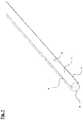
Figure 1 shows a cutaway perspective view of an inner tube manufactured by the method according to the present disclosure. -
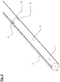
Figure 2 shows a cutaway perspective view of the inner tube offigure 1 with signal lines and sensors located thereon. -
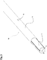
Figure 3 shows a cutaway perspective view of the inner tube offigures 1 and2 with an outer tube being concentric to the inner tube, wherein the inner tube and the outer tube have been manufactured by the method according to the disclosure. -
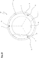
Figure 4 shows a top view onto the end face of the inner tube offigures 1 to 3 . -
Figure 5 shows a cross-sectional view of the inner tube offigures 1 to 3 in a plane in which the sensor is located. -
Figure 6 shows a cross-sectional view through the tube with the inner tube and the outer tube offigure 3 in a plane in which a sensor is located. -
Figure 7 shows a cross-sectional view in a longitudinal direction of an embodiment of a drawing die to carry out the method according to the disclosure and to manufacture the inner tube offigures 1 to 6 . -
Figure 8 shows a cross-sectional view in a lateral direction through the drawing die offigure 7 . -
Figure 9 shows a cross-sectional view of an alternative tube manufactured by an embodiment of the method according to the disclosure. -
Figure 10 shows a cross-sectional view of a tube manufactured by a method according to the present disclosure. - In the figures, identical elements have been denoted by identical reference numbers.
-
Figure 1 shows aninner tube 1, which comprises threegrooves 4 in itsouter surface 2. Thesegrooves 4 are provided to accommodate asignal line 7 in a tube manufactured from theinner tube 1 and an outer tube, which infigure 3 is denoted byreference number 5. - In the embodiment depicted, the
inner tube 1 is a cold formed, in this case a cold-drawn stainless steel tube. While thegrooves 4 are placed in theouter surface 2 of thetube 1 by drawing, therecesses 6 in theouter surface 2 of the tube are milled. -
Figures 7 and8 show adrawing die 9 for drawing theinner tube 1. The drawing die 9 reduces the outer diameter hollow fed in such that the readily drawninner tube 1 comprises an outer diameter which is defined by the tool dimension of the drawing die 9. In this case, the tool dimension in the sense of the present application denotes the smallest diameter of the conicalinner tool surface 10. This smallest inner diameter of the drawing die 9 offigure 7 is reached at the position denoted by 11. In addition to the drawing die 9, a mounted or floating mandrel may be used for drawing the hollow into thefinished tube 1 defining the inner dimension, i.e. the inner diameter of theinner tube 1. However, this is not obligatory. -
Figure 4 shows a cross-section through theinner tube 1 in an arbitrary plane outside therecess 6. The inner surface of theinner tube 1 is denoted byreference number 14. - For drawing of the
grooves 4 in theouter surface 2 of theinner tube 1, three projectingsections 12 are provided on the inner tool surface. Thesesections 12 projecting inwardly from the inner tool surface are distanced from each other by 120° each in a circumferential direction. Each of the sections projecting inwardly comprises a cross-section having the shape of a divided circle, wherein with reference to theinner tool surface 10, the divided circle of each of the sections projecting inwardly is smaller than 180°. This way, the grooves drawn by the drawing die 9 in theouter surface 2 of theinner tube 1 have a width in a circumferential direction of thetube 1 being smaller than their depth in a radial direction of thetube 1. - After drawing through the drawing die 9, the
inner tube 1 thus not only comprises its outer dimension and its inner dimension, but shows three grooves each being distant from the next groove by 120°. - The drawing die 9 of
figures 7 and8 in the sense of the present application is also denoted as the second drawing die. - After the drawing of the
inner tube 1,additional recesses 6 are milled in itsouter surface 2 such that therecesses 6 connect to thegrooves 4. -
Figure 5 shows a cross-sectional view of the tube in an area of therecess 6. In addition,figure 2 shows the inner tube with the already milled recesses 6. - Furthermore, in the
outer surface 2 of theinner tube 1, threerecesses 6 are provided to accommodate a sensor each being connected to asingle line 7 each. Only two of the threerecesses 6 are visible in the perspective view offigure 2 , the third one is hidden by thetube 1. - Each of the
recesses 6 connects to onegroove 4 in the sense that thegroove 4 and therecess 6 form a continuous accommodation space for thesignal lines 7 and for thesensors 8. - Next, the
signal lines 7 together with thesensors 8 are glued in thegrooves 4 and therecesses 6, respectively. With respect to this gluing, it is only relevant that the gluing is sufficiently stable in order to enable insertion of theinner tube 1 into theouter tube 5. In the shown embodiment, thegrooves 4 are dimensioned such that they accommodate twosignal lines 7 each. - Initially, in order to manufacture the complete tube, it is irrelevant how the
outer tube 5 is manufactured or provided. Typically, theouter tube 5 will be a cold formed tube of stainless steel. - It is crucial that the outer dimension of the
inner tube 1 is smaller than the inner dimension of theouter tube 5. In this way, theinner tube 1 with low friction at theouter tube 5 can be inserted with a small force into theouter tube 5. Once theinner tube 1 and theouter tube 5 comprise a friction being too high when inserting theinner tube 1 into theouter tube 5, thesignal lines 7 andsensors 8 already placed in thegrooves 4 and in therecesses 6 may be damaged. - Then the inner and
outer tubes tube 16 by drawing both tubes together on a drawing bench through a drawing die. This drawing die in the sense of the present application is denoted as the third drawing die. The third drawing die comprises a design corresponding to the design of the drawing die offigures 7 and8 , wherein the third drawing die does not comprise projecting sections on the shaping inner tool surface. It is crucial for this step of a method for manufacturing the tube that the inner diameter of theouter tube 5 is reduced such that the inner surface of theouter tube 5 sits on theouter surface 2 of theinner tube 1. In doing so, the tool dimension, i.e. the minimum tool diameter, IDz of the inner tool surface is chosen such that
- In the shown embodiment, the outer dimension of the incoming
inner tube 1 prior to the drawing through the third drawing die amounts to 25.4 mm and the wall thickness of the incoming inner tube amounts to 3 mm. The wall thickness of the incoming outer tube amounts to 1 mm and the reduction value amounts to 0.1 mm. Thereof, a tool dimension of 27.3 mm has been derived. - In the shown embodiment, the divided circle forming the
groove 4 has a radius of 0.5 mm. The divided circle is recessed in theouter surface 2 of theinner tube 1 such that the width of the groove measured as a connecting line between the two edges in a direction perpendicular to the longitudinal axis of theinner tube 1 amounts to 1.88 mm. The depth of thegroove 4 in this embodiment amounts to 0.7 mm measured between the point of the groove having the greatest depth and the connecting line between the two edges of the groove on theouter surface 2 and perpendicular to this connecting line.
Figure 6 shows a cross-sectional view of the completed tubes offigure 3 after drawing of theinner tube 1 and theouter tube 5 through the third drawing die. It is to be noted that theouter surface 2 of theinner tube 1 contacts theinner surface 14 of theouter tube 5.
The outer surface of theouter tube 5 in the figures is denoted byreference number 15.
In the shown embodiment, the second drawing die comprises a tool dimension, i.e. a minimum tool diameter of 27.3 mm. The outer diameter of the outer tube entering into the third drawing die amounts to 30 mm with a wall thickness of 1 mm. -
Figure 9 shows a tube 16', wherein the inner tube 1' has an outer surface 2' without grooves and recesses. Instead, threegrooves 13 are drawn into the outer tube 5' mounted onto the inner tube 1'. For this purpose, the outer tube has been drawn of a hollow, wherein as a tool a drawing die and a mounted mandrel have been used. This drawing die forms the first drawing die in the sense of the present application. - The
mandrel 2 on its tool surface defining the inner surface of the outer tube comprises three sections projecting outwardly to draw thegrooves 13 in the inner surface of the outer tube. In addition, it is possible that also in the inner surface 17' of the outer tube 5', recesses are provided in which sensors can be placed. These recesses can be inserted in the inner surface 17' by milling. -
Figure 10 shows a schematic cross-section through atube 16". In thistube 16", the inner surface 17' of the outer tube 5' as well as theouter surface 2 of theinner tube 1 each comprise fourgrooves grooves 4 of theinner tube 1 and thegrooves 13 of the outer tube 5' have been manufactured as it has been described for theinner tube 1 offigures 1 to 5 and for the outer tube 5' offigure 9 . Thegrooves -
- 1, 1'
- inner tube
- 2, 2'
- outer surface of the inner tube
- 4
- groove in the outer surface of the inner tube
- 5, 5'
- outer tube
- 6
- recess
- 7
- signal line
- 8
- sensor
- 9
- third drawing die
- 10
- inner tool surface of the drawing die
- 11
- tool dimension
- 12
- projecting section of the inner tool surface
- 13
- groove in the inner surface of the outer tube
- 14, 14'
- inner surface of the inner tube
- 15
- outer surface of the outer tube
- 16, 16', 16"
- tube
- 17, 17'
- inner surface of the outer tube
Claims (8)
- A method for manufacturing a tube (16,16') of metal, wherein the tube (16,16') comprises an outer surface (15) and an inner surface (14,14'), the method comprising the steps of,
providing an outer tube (5,5') of metal with an outer surface (15), an inner surface (17,17'), an outer dimension and an inner dimension,
providing an inner tube (1,1') of metal with an outer surface (2,2'), an inner surface (14,14'), an outer dimension and an inner dimension,
wherein providing the inner tube (1) comprises the steps of,- providing a hollow of metal,- drawing the hollow of metal through a second drawing die (9) having an inner tool surface (10) forming the outer surface (2) of the inner tube (1) into the inner tube (1),drawing the inner tube (1,1') and the outer tube (5,5') together through a third drawing die with an inner tool surface forming the outer surface (15) of the tube (16,16'), wherein a tool dimension of the inner tool surface of the third drawing die is chosen such that by the drawing the inner dimension of the outer tube (5,5') is reduced such that after drawing the outer tube (5,5') is force-fitted onto the inner tube (1,1') characterized in that prior to the step of inserting the inner tube (1,1') into the outer tube (5,5') at least one signal line (7) is placed in the groove (4) of the inner tube.
wherein the tool dimension of the inner tool surface (10) of the second drawing die (9) is chosen such that the outer dimension of the inner tube (1) is smaller than the inner dimension of the outer tube (5,5') and
wherein the inner tool surface (10) of the second drawing die (9) comprises at least a section (12) projecting inwardly, such that a groove (4) extending in a longitudinal direction of the inner tube (1) is drawn in the outer surface (2) of the inner tube (1),
wherein providing the outer tube (5,5') comprises optionally the steps of,- providing a hollow of metal,- drawing the hollow of metal through a first drawing die with an inner tool surface (10) forming the outer surface (15) of the outer tube (5') and over a mandrel with an outer tool surface forming the inner surface (17') of the outer tube (5') into the outer tube (5'),wherein a tool dimension of the inner tool surface of the first drawing die and a tool dimension of the outer tool surface of the mandrel are chosen such that the inner dimension of the outer tube (5,5') is larger than the outer dimension of the inner tube (1,1') and
wherein the outer tool surface of the mandrel comprises at least one outwardly projecting section such that a groove (13) extending in a longitudinal direction of the outer tube (5') is drawn in the inner surface (17') of the outer tube (5'), inserting the inner tube (1,1') into the outer tube (5,5') such that the inner tube (1,1') extends in the outer tube (5,5'), and - The method according to claim 1, wherein the signal line is chosen from a group consisting of a line for an electrical signal, a line for an electromagnetic signal, a line for an optical signal and a combination thereof.
- The method according to any one of the previous claims, characterized in that the outer tube (5,5') comprises a wall thickness prior to the drawing through the third drawing die and the tool dimension of the inner tool surface of the third drawing die is chosen such that the tool dimension of the inner tool surface of the third drawing die is equal to the outer dimension of the inner tube (1,1') prior to the drawing through the third drawing die plus twice the wall thickness of the outer tube (5,5') prior to the drawing through the third drawing die and minus a reduction value, wherein the reduction value amounts to at least 0.01 mm, such as at least 0.05 mm.
- The method according to any one of the previous claims, characterized in that at least the outer tool surface of the mandrel comprises a plurality of sections projecting outwardly or the inner tool surface (10) of the second drawing die (9) comprises a plurality of sections (12) projecting inwardly, such that a plurality of grooves (4, 13) is drawn in the inner surface (17) of the outer tube (5') or in the outer surface (2) of the inner tube (1) in a longitudinal direction.
- The method according to any one of the previous claims, characterized in that prior to the step of inserting the inner tube (1,1') into the outer tube (5,5') at least the outer tube (5') is worked by metal cutting, such that at least one recess is formed in the inner surface (17') of the outer tube (5'), wherein the recess is connected to at least one groove (13), or the inner tube (1) is worked by metal cutting such that at least one recess (6) is provided in the outer surface (2) of the inner tube (1), wherein the recess (6) connects to at least one groove.
- The method according to claim 5, characterized in that the recess (6) has a depth in a radial direction of the outer tube (5') or of the inner tube (1), wherein the depth of the recess (6) is equal to a depth of the groove (4,13) in the radial direction of the outer tube (5') or of the inner tube (1).
- The method according to any one of claims 3 to 6, characterized in that prior to the step of inserting the inner tube (1, 1') into the outer tube (5, 5') at least one sensor (8) is placed in the groove (4, 13) or in the recess (6), wherein the sensor (8) is connected to a signal line (7).
- The method according to claim 7, characterized in that the sensor (8) is chosen from a group consisting of an acceleration sensor, a vibration sensor, a conductivity sensor, a pressure sensor, a temperature sensor, a strain gauge, a corrosion sensor, a magnetic field sensor, a heat flux sensor and a torque sensor or any combination thereof.
Applications Claiming Priority (2)
| Application Number | Priority Date | Filing Date | Title |
|---|---|---|---|
| DE102015122295 | 2015-12-18 | ||
| PCT/EP2016/077810 WO2017102227A1 (en) | 2015-12-18 | 2016-11-16 | A method for manufacturing a tube of metal as well as a tube of metal |
Publications (2)
| Publication Number | Publication Date |
|---|---|
| EP3389886A1 EP3389886A1 (en) | 2018-10-24 |
| EP3389886B1 true EP3389886B1 (en) | 2021-06-23 |
Family
ID=57345929
Family Applications (1)
| Application Number | Title | Priority Date | Filing Date |
|---|---|---|---|
| EP16797863.4A Active EP3389886B1 (en) | 2015-12-18 | 2016-11-16 | A method for manufacturing a tube of metal |
Country Status (10)
| Country | Link |
|---|---|
| US (1) | US10724658B2 (en) |
| EP (1) | EP3389886B1 (en) |
| JP (2) | JP7102340B2 (en) |
| KR (1) | KR102696524B1 (en) |
| CN (1) | CN108778547B (en) |
| AU (1) | AU2016369860A1 (en) |
| BR (1) | BR112018012311B1 (en) |
| CA (1) | CA3008049A1 (en) |
| ES (1) | ES2887553T3 (en) |
| WO (1) | WO2017102227A1 (en) |
Families Citing this family (12)
| Publication number | Priority date | Publication date | Assignee | Title |
|---|---|---|---|---|
| DE102015122296A1 (en) * | 2015-12-18 | 2017-06-22 | Sandvik Materials Technology Deutschland Gmbh | Sensor for a high-pressure line and method for its production |
| BR112019017720A2 (en) * | 2017-02-28 | 2020-03-31 | Sandvik Intellectual Property Ab | A TUBE STRUCTURE WITH A PROTECTED SENSOR AND METHOD FOR MANUFACTURING A TUBE STRUCTURE WITH A PROTECTED SENSOR |
| CN110809498A (en) * | 2017-06-16 | 2020-02-18 | 山特维克知识产权股份有限公司 | Tube structure and method for manufacturing a tube structure |
| WO2019129862A1 (en) * | 2017-12-29 | 2019-07-04 | Sandvik Materials Technology Deutschland Gmbh | Downhole tubing or umbilical with sensor and method for manufacturing it |
| WO2019149604A1 (en) * | 2018-01-31 | 2019-08-08 | Tata Steel Nederland Technology B.V. | Tube segment and tube for evacuated tube transport system |
| US11953388B2 (en) | 2018-05-16 | 2024-04-09 | Alleima Tube Ab | Metallic tube structure with a sensor arrangement |
| ES2915528T3 (en) | 2018-06-20 | 2022-06-22 | Ab Sandvik Materials Tech | tube portion |
| JP7561132B2 (en) * | 2019-02-20 | 2024-10-03 | パラマウント・ダイ・カンパニー・インコーポレイテッド | Wire drawing monitoring system |
| EP3842776A1 (en) * | 2019-12-27 | 2021-06-30 | Tubacex Innovación A.I.E. | Assembly for monitoring the temperature and strain of a pipe |
| CN111195658B (en) * | 2020-01-08 | 2021-10-08 | 河北金奥精工技术有限公司 | Special-shaped rocker shaft seamless steel tube and forming method thereof |
| CN113414364B (en) * | 2021-06-21 | 2023-03-21 | 山西昌达盛精密铸造有限公司 | Solid-state double-metal inner wall wear-resistant material conveying circular pipe and preparation method thereof |
| CN113531233B (en) * | 2021-09-10 | 2021-11-30 | 江苏淮海新材料科技有限公司 | Industrial waste gas treatment pipe of convenient clearance |
Citations (2)
| Publication number | Priority date | Publication date | Assignee | Title |
|---|---|---|---|---|
| DE9110188U1 (en) * | 1991-08-17 | 1992-02-06 | Dipl.-Ing. Wrede u. Niedecken Verwaltung GmbH, 5047 Wesseling | Gas and/or liquid-carrying pipeline |
| US7042235B2 (en) * | 2003-08-09 | 2006-05-09 | Rittal Gmbh & Co. Kg | Method for the detection of leaks in components conducting liquids and device for executing the method |
Family Cites Families (29)
| Publication number | Priority date | Publication date | Assignee | Title |
|---|---|---|---|---|
| GB728131A (en) * | 1951-11-16 | 1955-04-13 | Foster Wheeler Ltd | Improvements in and relating to composite tubes |
| GB960628A (en) | 1961-03-29 | 1964-06-10 | Calumet & Hecla | Leak detector tube and method of making the same |
| SE7600738L (en) * | 1976-01-26 | 1977-07-27 | Electrolux Ab | VACUUM HOSE |
| US4216575A (en) | 1979-02-01 | 1980-08-12 | Noranda Mines Limited | Method of reforming the fins of a finned tube |
| DE3211441A1 (en) * | 1982-03-27 | 1983-09-29 | Kabel- und Metallwerke Gutehoffnungshütte AG, 3000 Hannover | METHOD FOR PRODUCING A TUBE WITH CHANNELS IN THE TUBE WALL |
| DE3706408C1 (en) * | 1987-02-27 | 1988-05-11 | Schmoele Metall R & G | Heat transfer tube |
| US4934579A (en) * | 1987-12-04 | 1990-06-19 | Compressor Components Textron Inc. | Attachment of dissimilar metals |
| JPH0716689B2 (en) * | 1990-05-22 | 1995-03-01 | 住友軽金属工業株式会社 | Inner surface high fin tube and inner surface high fin type double tube manufacturing method |
| DE4039863C1 (en) * | 1990-12-13 | 1992-02-13 | Bayer Ag, 5090 Leverkusen, De | Insulated double pipe - has nested pipes with foaming heat insulation in between, plus leakage sensor line below inner pipe, screened from insulation by cover film |
| JPH058820U (en) * | 1991-07-17 | 1993-02-05 | エスエムシー株式会社 | Fluid supply tube |
| DE4428875C2 (en) * | 1994-08-08 | 1996-10-24 | Mannesmann Ag | Hollow axis manufacturing method |
| JP2741844B2 (en) | 1994-11-28 | 1998-04-22 | サンキン株式会社 | Tube having internal partition and method of manufacturing the same |
| US5921285A (en) * | 1995-09-28 | 1999-07-13 | Fiberspar Spoolable Products, Inc. | Composite spoolable tube |
| US5857921A (en) | 1996-05-24 | 1999-01-12 | Fm Precision Golf Manufacturing Corp. | Golf club shafts |
| NL1004592C2 (en) * | 1996-11-22 | 1998-06-08 | Spiro Research Bv | Heat exchanger tube and manufacturing method therefor. |
| JP3021371B2 (en) | 1996-12-02 | 2000-03-15 | 酸素アーク工業株式会社 | Perforated tube and method of manufacturing the same |
| US7650724B2 (en) * | 2005-03-11 | 2010-01-26 | Hallett Canvas & Sails, Inc. | Tube with external channel |
| JP4429279B2 (en) * | 2006-03-13 | 2010-03-10 | スミテック鋼管株式会社 | Internally divided pipe and method for manufacturing the same |
| WO2007120642A2 (en) * | 2006-04-11 | 2007-10-25 | Daikin Industries, Ltd. | Dual-containment pipe containing fluoropolymer |
| DE102006047574A1 (en) * | 2006-10-05 | 2008-04-17 | Daimler Ag | Line optimization to prevent freezing |
| US9194512B2 (en) * | 2007-04-30 | 2015-11-24 | Mark Andreychuk | Coiled tubing with heat resistant conduit |
| CN101776184A (en) * | 2009-12-14 | 2010-07-14 | 深圳市协诚机电设备工程有限公司 | Double-layer metal pipe and manufacture mold and manufacturing method thereof |
| JP4897058B2 (en) * | 2010-01-14 | 2012-03-14 | 株式会社オートネットワーク技術研究所 | Shield conductive path |
| GB2479724B (en) * | 2010-04-19 | 2012-05-23 | Technip France | Umbilical |
| KR101600296B1 (en) * | 2010-08-18 | 2016-03-07 | 한온시스템 주식회사 | Double pipe heat exchanger and manufacturing method the same |
| CN102632102A (en) | 2012-04-16 | 2012-08-15 | 常熟市无缝钢管有限公司 | Machining method of abnormal tubular product for lift control switch |
| US9228428B2 (en) * | 2012-12-26 | 2016-01-05 | General Electric Company | System and method for monitoring tubular components of a subsea structure |
| CN103157694B (en) | 2013-02-21 | 2015-05-06 | 山西太钢不锈钢股份有限公司 | Manufacturing method of steel tube provided with rack-shaped inner wall |
| CN204817505U (en) | 2015-07-23 | 2015-12-02 | 江苏久立管业有限公司 | Inner groovy cold drawing dysmorphism tubular product |
-
2016
- 2016-11-16 AU AU2016369860A patent/AU2016369860A1/en not_active Abandoned
- 2016-11-16 CN CN201680074307.3A patent/CN108778547B/en active Active
- 2016-11-16 US US16/061,370 patent/US10724658B2/en active Active
- 2016-11-16 BR BR112018012311-0A patent/BR112018012311B1/en active IP Right Grant
- 2016-11-16 EP EP16797863.4A patent/EP3389886B1/en active Active
- 2016-11-16 WO PCT/EP2016/077810 patent/WO2017102227A1/en not_active Ceased
- 2016-11-16 ES ES16797863T patent/ES2887553T3/en active Active
- 2016-11-16 JP JP2018531496A patent/JP7102340B2/en active Active
- 2016-11-16 KR KR1020187020368A patent/KR102696524B1/en active Active
- 2016-11-16 CA CA3008049A patent/CA3008049A1/en not_active Abandoned
-
2021
- 2021-06-22 JP JP2021102843A patent/JP2021181119A/en active Pending
Patent Citations (2)
| Publication number | Priority date | Publication date | Assignee | Title |
|---|---|---|---|---|
| DE9110188U1 (en) * | 1991-08-17 | 1992-02-06 | Dipl.-Ing. Wrede u. Niedecken Verwaltung GmbH, 5047 Wesseling | Gas and/or liquid-carrying pipeline |
| US7042235B2 (en) * | 2003-08-09 | 2006-05-09 | Rittal Gmbh & Co. Kg | Method for the detection of leaks in components conducting liquids and device for executing the method |
Also Published As
| Publication number | Publication date |
|---|---|
| CN108778547B (en) | 2021-02-09 |
| WO2017102227A1 (en) | 2017-06-22 |
| ES2887553T3 (en) | 2021-12-23 |
| KR20180096690A (en) | 2018-08-29 |
| BR112018012311B1 (en) | 2022-03-22 |
| AU2016369860A1 (en) | 2018-06-28 |
| KR102696524B1 (en) | 2024-08-19 |
| CN108778547A (en) | 2018-11-09 |
| CA3008049A1 (en) | 2017-06-22 |
| JP2019503867A (en) | 2019-02-14 |
| JP7102340B2 (en) | 2022-07-19 |
| US20180356009A1 (en) | 2018-12-13 |
| US10724658B2 (en) | 2020-07-28 |
| JP2021181119A (en) | 2021-11-25 |
| BR112018012311A2 (en) | 2018-12-04 |
| EP3389886A1 (en) | 2018-10-24 |
Similar Documents
| Publication | Publication Date | Title |
|---|---|---|
| US10724658B2 (en) | Method for manufacturing a tube of metal as well as a tube of metal | |
| US10799094B2 (en) | Connection structure for wire protective sheath, connection member, wire protective sheath structure, and connection method for wire protective sheath | |
| EP3521744A1 (en) | Heat exchange assembly for heat exchanger, heat exchanger, and mold | |
| US11112063B2 (en) | Sensor for a high-pressure line, and method for producing same | |
| CN102082470B (en) | Laminated stator core | |
| CN109804532A (en) | The manufacturing method of laminated iron core | |
| JP6998952B2 (en) | Systems and methods for manufacturing systems | |
| CN101918158B (en) | Method of manufacturing metal member with plurality of projections | |
| EP2676864B1 (en) | Rack bar and rack bar teeth forming die | |
| KR20200007078A (en) | Tube Structures and Methods for Manufacturing Tube Structures | |
| CA2950052A1 (en) | Flex shaft | |
| EP3589874B1 (en) | A tube structure with a protected sensor and method for manufacturing a tube structure with a protected sensor | |
| US20120137520A1 (en) | Integrated valve sleeve | |
| EP3069982B1 (en) | Method for manufacturing a bicycle front fork having a wheel clamping base | |
| JP4241506B2 (en) | Method for manufacturing glow plug metal shell and method for manufacturing glow plug | |
| CN202461168U (en) | Extrusion head of cold extrusion mold for klystron cavity | |
| CN115740349A (en) | Continuous cold heading manufacturing process for rear wheel of jack | |
| CN102378661B (en) | Billet for cutting tool, composite billet, cutting tool, and method for manufacturing billet for cutting tool | |
| RU2060084C1 (en) | Method of making adaptors with outer cylindrical land | |
| JP2006312979A (en) | Manufacturing method of connecting rod |
Legal Events
| Date | Code | Title | Description |
|---|---|---|---|
| STAA | Information on the status of an ep patent application or granted ep patent |
Free format text: STATUS: UNKNOWN |
|
| STAA | Information on the status of an ep patent application or granted ep patent |
Free format text: STATUS: THE INTERNATIONAL PUBLICATION HAS BEEN MADE |
|
| PUAI | Public reference made under article 153(3) epc to a published international application that has entered the european phase |
Free format text: ORIGINAL CODE: 0009012 |
|
| STAA | Information on the status of an ep patent application or granted ep patent |
Free format text: STATUS: REQUEST FOR EXAMINATION WAS MADE |
|
| 17P | Request for examination filed |
Effective date: 20180718 |
|
| AK | Designated contracting states |
Kind code of ref document: A1 Designated state(s): AL AT BE BG CH CY CZ DE DK EE ES FI FR GB GR HR HU IE IS IT LI LT LU LV MC MK MT NL NO PL PT RO RS SE SI SK SM TR |
|
| AX | Request for extension of the european patent |
Extension state: BA ME |
|
| DAV | Request for validation of the european patent (deleted) | ||
| DAX | Request for extension of the european patent (deleted) | ||
| STAA | Information on the status of an ep patent application or granted ep patent |
Free format text: STATUS: EXAMINATION IS IN PROGRESS |
|
| 17Q | First examination report despatched |
Effective date: 20200302 |
|
| GRAP | Despatch of communication of intention to grant a patent |
Free format text: ORIGINAL CODE: EPIDOSNIGR1 |
|
| STAA | Information on the status of an ep patent application or granted ep patent |
Free format text: STATUS: GRANT OF PATENT IS INTENDED |
|
| INTG | Intention to grant announced |
Effective date: 20210222 |
|
| GRAS | Grant fee paid |
Free format text: ORIGINAL CODE: EPIDOSNIGR3 |
|
| GRAA | (expected) grant |
Free format text: ORIGINAL CODE: 0009210 |
|
| STAA | Information on the status of an ep patent application or granted ep patent |
Free format text: STATUS: THE PATENT HAS BEEN GRANTED |
|
| AK | Designated contracting states |
Kind code of ref document: B1 Designated state(s): AL AT BE BG CH CY CZ DE DK EE ES FI FR GB GR HR HU IE IS IT LI LT LU LV MC MK MT NL NO PL PT RO RS SE SI SK SM TR |
|
| REG | Reference to a national code |
Ref country code: GB Ref legal event code: FG4D |
|
| REG | Reference to a national code |
Ref country code: CH Ref legal event code: EP |
|
| REG | Reference to a national code |
Ref country code: DE Ref legal event code: R096 Ref document number: 602016059723 Country of ref document: DE Ref country code: AT Ref legal event code: REF Ref document number: 1403855 Country of ref document: AT Kind code of ref document: T Effective date: 20210715 |
|
| REG | Reference to a national code |
Ref country code: IE Ref legal event code: FG4D |
|
| REG | Reference to a national code |
Ref country code: SE Ref legal event code: TRGR |
|
| REG | Reference to a national code |
Ref country code: LT Ref legal event code: MG9D |
|
| PG25 | Lapsed in a contracting state [announced via postgrant information from national office to epo] |
Ref country code: LT Free format text: LAPSE BECAUSE OF FAILURE TO SUBMIT A TRANSLATION OF THE DESCRIPTION OR TO PAY THE FEE WITHIN THE PRESCRIBED TIME-LIMIT Effective date: 20210623 Ref country code: FI Free format text: LAPSE BECAUSE OF FAILURE TO SUBMIT A TRANSLATION OF THE DESCRIPTION OR TO PAY THE FEE WITHIN THE PRESCRIBED TIME-LIMIT Effective date: 20210623 Ref country code: BG Free format text: LAPSE BECAUSE OF FAILURE TO SUBMIT A TRANSLATION OF THE DESCRIPTION OR TO PAY THE FEE WITHIN THE PRESCRIBED TIME-LIMIT Effective date: 20210923 Ref country code: HR Free format text: LAPSE BECAUSE OF FAILURE TO SUBMIT A TRANSLATION OF THE DESCRIPTION OR TO PAY THE FEE WITHIN THE PRESCRIBED TIME-LIMIT Effective date: 20210623 |
|
| REG | Reference to a national code |
Ref country code: AT Ref legal event code: MK05 Ref document number: 1403855 Country of ref document: AT Kind code of ref document: T Effective date: 20210623 |
|
| PG25 | Lapsed in a contracting state [announced via postgrant information from national office to epo] |
Ref country code: NO Free format text: LAPSE BECAUSE OF FAILURE TO SUBMIT A TRANSLATION OF THE DESCRIPTION OR TO PAY THE FEE WITHIN THE PRESCRIBED TIME-LIMIT Effective date: 20210923 Ref country code: RS Free format text: LAPSE BECAUSE OF FAILURE TO SUBMIT A TRANSLATION OF THE DESCRIPTION OR TO PAY THE FEE WITHIN THE PRESCRIBED TIME-LIMIT Effective date: 20210623 Ref country code: GR Free format text: LAPSE BECAUSE OF FAILURE TO SUBMIT A TRANSLATION OF THE DESCRIPTION OR TO PAY THE FEE WITHIN THE PRESCRIBED TIME-LIMIT Effective date: 20210924 Ref country code: LV Free format text: LAPSE BECAUSE OF FAILURE TO SUBMIT A TRANSLATION OF THE DESCRIPTION OR TO PAY THE FEE WITHIN THE PRESCRIBED TIME-LIMIT Effective date: 20210623 |
|
| REG | Reference to a national code |
Ref country code: NL Ref legal event code: MP Effective date: 20210623 |
|
| REG | Reference to a national code |
Ref country code: ES Ref legal event code: FG2A Ref document number: 2887553 Country of ref document: ES Kind code of ref document: T3 Effective date: 20211223 |
|
| PG25 | Lapsed in a contracting state [announced via postgrant information from national office to epo] |
Ref country code: CZ Free format text: LAPSE BECAUSE OF FAILURE TO SUBMIT A TRANSLATION OF THE DESCRIPTION OR TO PAY THE FEE WITHIN THE PRESCRIBED TIME-LIMIT Effective date: 20210623 Ref country code: EE Free format text: LAPSE BECAUSE OF FAILURE TO SUBMIT A TRANSLATION OF THE DESCRIPTION OR TO PAY THE FEE WITHIN THE PRESCRIBED TIME-LIMIT Effective date: 20210623 Ref country code: SK Free format text: LAPSE BECAUSE OF FAILURE TO SUBMIT A TRANSLATION OF THE DESCRIPTION OR TO PAY THE FEE WITHIN THE PRESCRIBED TIME-LIMIT Effective date: 20210623 Ref country code: SM Free format text: LAPSE BECAUSE OF FAILURE TO SUBMIT A TRANSLATION OF THE DESCRIPTION OR TO PAY THE FEE WITHIN THE PRESCRIBED TIME-LIMIT Effective date: 20210623 Ref country code: AT Free format text: LAPSE BECAUSE OF FAILURE TO SUBMIT A TRANSLATION OF THE DESCRIPTION OR TO PAY THE FEE WITHIN THE PRESCRIBED TIME-LIMIT Effective date: 20210623 Ref country code: NL Free format text: LAPSE BECAUSE OF FAILURE TO SUBMIT A TRANSLATION OF THE DESCRIPTION OR TO PAY THE FEE WITHIN THE PRESCRIBED TIME-LIMIT Effective date: 20210623 Ref country code: PT Free format text: LAPSE BECAUSE OF FAILURE TO SUBMIT A TRANSLATION OF THE DESCRIPTION OR TO PAY THE FEE WITHIN THE PRESCRIBED TIME-LIMIT Effective date: 20211025 Ref country code: RO Free format text: LAPSE BECAUSE OF FAILURE TO SUBMIT A TRANSLATION OF THE DESCRIPTION OR TO PAY THE FEE WITHIN THE PRESCRIBED TIME-LIMIT Effective date: 20210623 |
|
| PG25 | Lapsed in a contracting state [announced via postgrant information from national office to epo] |
Ref country code: PL Free format text: LAPSE BECAUSE OF FAILURE TO SUBMIT A TRANSLATION OF THE DESCRIPTION OR TO PAY THE FEE WITHIN THE PRESCRIBED TIME-LIMIT Effective date: 20210623 |
|
| REG | Reference to a national code |
Ref country code: DE Ref legal event code: R097 Ref document number: 602016059723 Country of ref document: DE |
|
| PG25 | Lapsed in a contracting state [announced via postgrant information from national office to epo] |
Ref country code: DK Free format text: LAPSE BECAUSE OF FAILURE TO SUBMIT A TRANSLATION OF THE DESCRIPTION OR TO PAY THE FEE WITHIN THE PRESCRIBED TIME-LIMIT Effective date: 20210623 |
|
| PLBE | No opposition filed within time limit |
Free format text: ORIGINAL CODE: 0009261 |
|
| STAA | Information on the status of an ep patent application or granted ep patent |
Free format text: STATUS: NO OPPOSITION FILED WITHIN TIME LIMIT |
|
| 26N | No opposition filed |
Effective date: 20220324 |
|
| PG25 | Lapsed in a contracting state [announced via postgrant information from national office to epo] |
Ref country code: AL Free format text: LAPSE BECAUSE OF FAILURE TO SUBMIT A TRANSLATION OF THE DESCRIPTION OR TO PAY THE FEE WITHIN THE PRESCRIBED TIME-LIMIT Effective date: 20210623 |
|
| PG25 | Lapsed in a contracting state [announced via postgrant information from national office to epo] |
Ref country code: MC Free format text: LAPSE BECAUSE OF FAILURE TO SUBMIT A TRANSLATION OF THE DESCRIPTION OR TO PAY THE FEE WITHIN THE PRESCRIBED TIME-LIMIT Effective date: 20210623 |
|
| REG | Reference to a national code |
Ref country code: CH Ref legal event code: PL |
|
| PG25 | Lapsed in a contracting state [announced via postgrant information from national office to epo] |
Ref country code: LU Free format text: LAPSE BECAUSE OF NON-PAYMENT OF DUE FEES Effective date: 20211116 Ref country code: IT Free format text: LAPSE BECAUSE OF FAILURE TO SUBMIT A TRANSLATION OF THE DESCRIPTION OR TO PAY THE FEE WITHIN THE PRESCRIBED TIME-LIMIT Effective date: 20210623 Ref country code: BE Free format text: LAPSE BECAUSE OF NON-PAYMENT OF DUE FEES Effective date: 20211130 |
|
| REG | Reference to a national code |
Ref country code: BE Ref legal event code: MM Effective date: 20211130 |
|
| PG25 | Lapsed in a contracting state [announced via postgrant information from national office to epo] |
Ref country code: IE Free format text: LAPSE BECAUSE OF NON-PAYMENT OF DUE FEES Effective date: 20211116 |
|
| PG25 | Lapsed in a contracting state [announced via postgrant information from national office to epo] |
Ref country code: HU Free format text: LAPSE BECAUSE OF FAILURE TO SUBMIT A TRANSLATION OF THE DESCRIPTION OR TO PAY THE FEE WITHIN THE PRESCRIBED TIME-LIMIT; INVALID AB INITIO Effective date: 20161116 |
|
| PG25 | Lapsed in a contracting state [announced via postgrant information from national office to epo] |
Ref country code: CY Free format text: LAPSE BECAUSE OF FAILURE TO SUBMIT A TRANSLATION OF THE DESCRIPTION OR TO PAY THE FEE WITHIN THE PRESCRIBED TIME-LIMIT Effective date: 20210623 |
|
| P01 | Opt-out of the competence of the unified patent court (upc) registered |
Effective date: 20230526 |
|
| PG25 | Lapsed in a contracting state [announced via postgrant information from national office to epo] |
Ref country code: LI Free format text: LAPSE BECAUSE OF NON-PAYMENT OF DUE FEES Effective date: 20220630 Ref country code: CH Free format text: LAPSE BECAUSE OF NON-PAYMENT OF DUE FEES Effective date: 20220630 |
|
| REG | Reference to a national code |
Ref country code: DE Ref legal event code: R081 Ref document number: 602016059723 Country of ref document: DE Owner name: ALLEIMA GMBH, DE Free format text: FORMER OWNER: SANDVIK MATERIALS TECHNOLOGY DEUTSCHLAND GMBH, 40549 DUESSELDORF, DE |
|
| PG25 | Lapsed in a contracting state [announced via postgrant information from national office to epo] |
Ref country code: MK Free format text: LAPSE BECAUSE OF FAILURE TO SUBMIT A TRANSLATION OF THE DESCRIPTION OR TO PAY THE FEE WITHIN THE PRESCRIBED TIME-LIMIT Effective date: 20210623 |
|
| PG25 | Lapsed in a contracting state [announced via postgrant information from national office to epo] |
Ref country code: TR Free format text: LAPSE BECAUSE OF FAILURE TO SUBMIT A TRANSLATION OF THE DESCRIPTION OR TO PAY THE FEE WITHIN THE PRESCRIBED TIME-LIMIT Effective date: 20210623 |
|
| PG25 | Lapsed in a contracting state [announced via postgrant information from national office to epo] |
Ref country code: MT Free format text: LAPSE BECAUSE OF FAILURE TO SUBMIT A TRANSLATION OF THE DESCRIPTION OR TO PAY THE FEE WITHIN THE PRESCRIBED TIME-LIMIT Effective date: 20210623 |
|
| REG | Reference to a national code |
Ref country code: ES Ref legal event code: PC2A Owner name: ALLEIMA GMBH Effective date: 20240930 |
|
| PGFP | Annual fee paid to national office [announced via postgrant information from national office to epo] |
Ref country code: DE Payment date: 20251007 Year of fee payment: 10 |
|
| PGFP | Annual fee paid to national office [announced via postgrant information from national office to epo] |
Ref country code: GB Payment date: 20251016 Year of fee payment: 10 |
|
| PGFP | Annual fee paid to national office [announced via postgrant information from national office to epo] |
Ref country code: FR Payment date: 20251023 Year of fee payment: 10 |
|
| PGFP | Annual fee paid to national office [announced via postgrant information from national office to epo] |
Ref country code: SE Payment date: 20251010 Year of fee payment: 10 |
|
| PGFP | Annual fee paid to national office [announced via postgrant information from national office to epo] |
Ref country code: ES Payment date: 20251212 Year of fee payment: 10 |