EP3389739B1 - Hohldübel - Google Patents
Hohldübel Download PDFInfo
- Publication number
- EP3389739B1 EP3389739B1 EP16840354.1A EP16840354A EP3389739B1 EP 3389739 B1 EP3389739 B1 EP 3389739B1 EP 16840354 A EP16840354 A EP 16840354A EP 3389739 B1 EP3389739 B1 EP 3389739B1
- Authority
- EP
- European Patent Office
- Prior art keywords
- plug
- adaptor
- mounting
- way valve
- gimbal
- Prior art date
- Legal status (The legal status is an assumption and is not a legal conclusion. Google has not performed a legal analysis and makes no representation as to the accuracy of the status listed.)
- Active
Links
Images


Classifications
-
- A—HUMAN NECESSITIES
- A61—MEDICAL OR VETERINARY SCIENCE; HYGIENE
- A61F—FILTERS IMPLANTABLE INTO BLOOD VESSELS; PROSTHESES; DEVICES PROVIDING PATENCY TO, OR PREVENTING COLLAPSING OF, TUBULAR STRUCTURES OF THE BODY, e.g. STENTS; ORTHOPAEDIC, NURSING OR CONTRACEPTIVE DEVICES; FOMENTATION; TREATMENT OR PROTECTION OF EYES OR EARS; BANDAGES, DRESSINGS OR ABSORBENT PADS; FIRST-AID KITS
- A61F2/00—Filters implantable into blood vessels; Prostheses, i.e. artificial substitutes or replacements for parts of the body; Appliances for connecting them with the body; Devices providing patency to, or preventing collapsing of, tubular structures of the body, e.g. stents
- A61F2/02—Prostheses implantable into the body
- A61F2/24—Heart valves ; Vascular valves, e.g. venous valves; Heart implants, e.g. passive devices for improving the function of the native valve or the heart muscle; Transmyocardial revascularisation [TMR] devices; Valves implantable in the body
- A61F2/2427—Devices for manipulating or deploying heart valves during implantation
-
- A—HUMAN NECESSITIES
- A61—MEDICAL OR VETERINARY SCIENCE; HYGIENE
- A61B—DIAGNOSIS; SURGERY; IDENTIFICATION
- A61B17/00—Surgical instruments, devices or methods
- A61B17/32—Surgical cutting instruments
- A61B17/320016—Endoscopic cutting instruments, e.g. arthroscopes, resectoscopes
-
- A—HUMAN NECESSITIES
- A61—MEDICAL OR VETERINARY SCIENCE; HYGIENE
- A61F—FILTERS IMPLANTABLE INTO BLOOD VESSELS; PROSTHESES; DEVICES PROVIDING PATENCY TO, OR PREVENTING COLLAPSING OF, TUBULAR STRUCTURES OF THE BODY, e.g. STENTS; ORTHOPAEDIC, NURSING OR CONTRACEPTIVE DEVICES; FOMENTATION; TREATMENT OR PROTECTION OF EYES OR EARS; BANDAGES, DRESSINGS OR ABSORBENT PADS; FIRST-AID KITS
- A61F2/00—Filters implantable into blood vessels; Prostheses, i.e. artificial substitutes or replacements for parts of the body; Appliances for connecting them with the body; Devices providing patency to, or preventing collapsing of, tubular structures of the body, e.g. stents
- A61F2/02—Prostheses implantable into the body
- A61F2/24—Heart valves ; Vascular valves, e.g. venous valves; Heart implants, e.g. passive devices for improving the function of the native valve or the heart muscle; Transmyocardial revascularisation [TMR] devices; Valves implantable in the body
- A61F2/2409—Support rings therefor, e.g. for connecting valves to tissue
-
- A—HUMAN NECESSITIES
- A61—MEDICAL OR VETERINARY SCIENCE; HYGIENE
- A61M—DEVICES FOR INTRODUCING MEDIA INTO, OR ONTO, THE BODY; DEVICES FOR TRANSDUCING BODY MEDIA OR FOR TAKING MEDIA FROM THE BODY; DEVICES FOR PRODUCING OR ENDING SLEEP OR STUPOR
- A61M60/00—Blood pumps; Devices for mechanical circulatory actuation; Balloon pumps for circulatory assistance
- A61M60/10—Location thereof with respect to the patient's body
- A61M60/122—Implantable pumps or pumping devices, i.e. the blood being pumped inside the patient's body
- A61M60/126—Implantable pumps or pumping devices, i.e. the blood being pumped inside the patient's body implantable via, into, inside, in line, branching on, or around a blood vessel
- A61M60/148—Implantable pumps or pumping devices, i.e. the blood being pumped inside the patient's body implantable via, into, inside, in line, branching on, or around a blood vessel in line with a blood vessel using resection or like techniques, e.g. permanent endovascular heart assist devices
-
- A—HUMAN NECESSITIES
- A61—MEDICAL OR VETERINARY SCIENCE; HYGIENE
- A61M—DEVICES FOR INTRODUCING MEDIA INTO, OR ONTO, THE BODY; DEVICES FOR TRANSDUCING BODY MEDIA OR FOR TAKING MEDIA FROM THE BODY; DEVICES FOR PRODUCING OR ENDING SLEEP OR STUPOR
- A61M60/00—Blood pumps; Devices for mechanical circulatory actuation; Balloon pumps for circulatory assistance
- A61M60/10—Location thereof with respect to the patient's body
- A61M60/122—Implantable pumps or pumping devices, i.e. the blood being pumped inside the patient's body
- A61M60/165—Implantable pumps or pumping devices, i.e. the blood being pumped inside the patient's body implantable in, on, or around the heart
- A61M60/178—Implantable pumps or pumping devices, i.e. the blood being pumped inside the patient's body implantable in, on, or around the heart drawing blood from a ventricle and returning the blood to the arterial system via a cannula external to the ventricle, e.g. left or right ventricular assist devices
-
- A—HUMAN NECESSITIES
- A61—MEDICAL OR VETERINARY SCIENCE; HYGIENE
- A61M—DEVICES FOR INTRODUCING MEDIA INTO, OR ONTO, THE BODY; DEVICES FOR TRANSDUCING BODY MEDIA OR FOR TAKING MEDIA FROM THE BODY; DEVICES FOR PRODUCING OR ENDING SLEEP OR STUPOR
- A61M60/00—Blood pumps; Devices for mechanical circulatory actuation; Balloon pumps for circulatory assistance
- A61M60/80—Constructional details other than related to driving
- A61M60/855—Constructional details other than related to driving of implantable pumps or pumping devices
- A61M60/857—Implantable blood tubes
- A61M60/859—Connections therefor
-
- A—HUMAN NECESSITIES
- A61—MEDICAL OR VETERINARY SCIENCE; HYGIENE
- A61M—DEVICES FOR INTRODUCING MEDIA INTO, OR ONTO, THE BODY; DEVICES FOR TRANSDUCING BODY MEDIA OR FOR TAKING MEDIA FROM THE BODY; DEVICES FOR PRODUCING OR ENDING SLEEP OR STUPOR
- A61M60/00—Blood pumps; Devices for mechanical circulatory actuation; Balloon pumps for circulatory assistance
- A61M60/80—Constructional details other than related to driving
- A61M60/855—Constructional details other than related to driving of implantable pumps or pumping devices
- A61M60/861—Connections or anchorings for connecting or anchoring pumps or pumping devices to parts of the patient's body
- A61M60/863—Apex rings
-
- A—HUMAN NECESSITIES
- A61—MEDICAL OR VETERINARY SCIENCE; HYGIENE
- A61M—DEVICES FOR INTRODUCING MEDIA INTO, OR ONTO, THE BODY; DEVICES FOR TRANSDUCING BODY MEDIA OR FOR TAKING MEDIA FROM THE BODY; DEVICES FOR PRODUCING OR ENDING SLEEP OR STUPOR
- A61M60/00—Blood pumps; Devices for mechanical circulatory actuation; Balloon pumps for circulatory assistance
- A61M60/80—Constructional details other than related to driving
- A61M60/855—Constructional details other than related to driving of implantable pumps or pumping devices
- A61M60/865—Devices for guiding or inserting pumps or pumping devices into the patient's body
-
- A—HUMAN NECESSITIES
- A61—MEDICAL OR VETERINARY SCIENCE; HYGIENE
- A61M—DEVICES FOR INTRODUCING MEDIA INTO, OR ONTO, THE BODY; DEVICES FOR TRANSDUCING BODY MEDIA OR FOR TAKING MEDIA FROM THE BODY; DEVICES FOR PRODUCING OR ENDING SLEEP OR STUPOR
- A61M60/00—Blood pumps; Devices for mechanical circulatory actuation; Balloon pumps for circulatory assistance
- A61M60/80—Constructional details other than related to driving
- A61M60/855—Constructional details other than related to driving of implantable pumps or pumping devices
- A61M60/89—Valves
- A61M60/894—Passive valves, i.e. valves actuated by the blood
- A61M60/896—Passive valves, i.e. valves actuated by the blood having flexible or resilient parts, e.g. flap valves
-
- A—HUMAN NECESSITIES
- A61—MEDICAL OR VETERINARY SCIENCE; HYGIENE
- A61B—DIAGNOSIS; SURGERY; IDENTIFICATION
- A61B17/00—Surgical instruments, devices or methods
- A61B17/00234—Surgical instruments, devices or methods for minimally invasive surgery
- A61B2017/00238—Type of minimally invasive operation
- A61B2017/00243—Type of minimally invasive operation cardiac
- A61B2017/00247—Making holes in the wall of the heart, e.g. laser Myocardial revascularization
-
- A—HUMAN NECESSITIES
- A61—MEDICAL OR VETERINARY SCIENCE; HYGIENE
- A61B—DIAGNOSIS; SURGERY; IDENTIFICATION
- A61B17/00—Surgical instruments, devices or methods
- A61B17/32—Surgical cutting instruments
- A61B2017/320052—Guides for cutting instruments
-
- A—HUMAN NECESSITIES
- A61—MEDICAL OR VETERINARY SCIENCE; HYGIENE
- A61M—DEVICES FOR INTRODUCING MEDIA INTO, OR ONTO, THE BODY; DEVICES FOR TRANSDUCING BODY MEDIA OR FOR TAKING MEDIA FROM THE BODY; DEVICES FOR PRODUCING OR ENDING SLEEP OR STUPOR
- A61M39/00—Tubes, tube connectors, tube couplings, valves, access sites or the like, specially adapted for medical use
- A61M39/22—Valves or arrangement of valves
- A61M39/24—Check- or non-return valves
- A61M2039/2433—Valve comprising a resilient or deformable element, e.g. flap valve, deformable disc
- A61M2039/244—Hinged closure member, e.g. flap valve
-
- A—HUMAN NECESSITIES
- A61—MEDICAL OR VETERINARY SCIENCE; HYGIENE
- A61M—DEVICES FOR INTRODUCING MEDIA INTO, OR ONTO, THE BODY; DEVICES FOR TRANSDUCING BODY MEDIA OR FOR TAKING MEDIA FROM THE BODY; DEVICES FOR PRODUCING OR ENDING SLEEP OR STUPOR
- A61M2210/00—Anatomical parts of the body
- A61M2210/12—Blood circulatory system
- A61M2210/125—Heart
Definitions
- the present invention relates to components and methods used for mounting devices such as ventricular assist devices and associated elements to the heart of a living subject.
- MCSD mechanical circulatory support device
- An MCSD is most commonly connected to the left ventricle.
- an inlet end of the pump, or an inlet cannula connected to the inlet end of the pump is implanted in the wall of the ventricle, such as at the apex of the ventricle.
- An outlet cannula is connected between the outlet end of the pump and an artery such as the aorta.
- MCSDs which are connected to a ventricle commonly are referred to as ventricular assist devices or "VADs.” During operation, the VAD assists the heart to pump blood from the left ventricle to the aorta.
- a mounting ring has a body and a bore extending through the body, and also has features which can be used to attach the body to the outside of the heart wall so that the bore extends towards and away from the wall.
- some mounting rings are equipped with a ring of fabric encircling the body, so that the mounting ring can be secured in place by suturing.
- Other mounting rings are equipped with barbs or other fasteners for attaching the body of the ring to the heart wall.
- Some mounting rings incorporate an element referred to as a gimbal which is pivotally mounted to the body of the mounting ring and which defines the bore of the mounting ring. The gimbal can be tilted to align the axis of the bore.
- a cruciate cut is made in the heart wall within the bore of the mounting ring and a separate surgical tool is used to core a hole in the heart.
- the pump, or an inlet cannula connected to the pump, is then inserted through the hole into the heart and secured to the mounting ring.
- the mounting ring is equipped with a gimbal, the gimbal can be tilted to align the axis of the pump or cannula with the anatomical features of the heart.
- the seal between the heart and mounting ring must be sufficiently tight to prevent blood loss from the heart. Also, the attachment between the heart and the ring must remain secure despite mechanical stresses and the attachment procedure should minimize damage to the wall of the heart.
- WO 2012/158919 A2 relates to a coring knife.
- a mounting kit includes a mounting element defining a bore, the mounting element being configured to mount to an exterior surface of an organ of a patient.
- a one way valve sized to be received and retained within the bore of the mounting element is included, the one way valve has an open position and a closed position. The one way valve substantially occludes the bore when the valve is in the closed position. The one way valve is biased in the closed position.
- a plug having a lumen extending there through is included, the plug is configured to be releasably inserted through at least a portion of the one way valve. The plug is configured to transition the one way valve from the closed position to the open position and to maintain the one way valve in the open position when the plug is inserted within the bore.
- the plug has a flange configured to provide for a maximum depth insertion of the plug within the bore.
- the one way valve is one from the group consisting of a tri-leaflet valve, flap valve, butterfly valve, and duckbill valve.
- the mounting element includes a ring defining an opening, the ring being configured to be anchored to the exterior surface of the organ.
- the mounting element includes an adaptor sized to be received within the opening of the ring, the adaptor defining an aperture, the opening of the ring being substantially co-axial when then adapter is received within the opening of the ring.
- the adaptor defines an annular wall defining a plurality of slits, and wherein at least a portion of the annular wall is flexible.
- the adaptor is configured to receive and retain at least one from the group consisting of a pump and a cannula within the bore.
- the mounting element further includes gimbal sized to be received and retained within the aperture of the adaptor, the gimbal defining an orifice, the gimbal being configured to tilt the alignment of the orifice with respect to the aperture of the adaptor when the gimbal is received within the aperture of the adaptor.
- the gimbal is substantially co-axial to the adaptor when the gimbal is received within the aperture of the adaptor.
- the gimbal defines an outer wall surrounding the orifice, and wherein at least a portion of the outer wall is flexible.
- the organ is the heart.
- the plug is configured to releasably mount to a cutting device.
- a method of creating an access way into the heart includes mounting a mounting element to external surface of the heart.
- the mounting element defines a bore sized to receive a one way valve disposed therein.
- the one way valve defines an open position and a closed position.
- the one way valve substantially occludes the bore when the valve is in the closed position.
- the valve is biased in the closed position.
- a plug is inserted through the one way valve, the plug defines a lumen there through and is configured to transition the one way valve from the closed position to the open position and to maintain the one way valve in the open position when the plug is inserted within the bore.
- the external surface of the heart is cut through the lumen of the plug.
- the method further includes removing the plug from the bore after cutting the external surface of the tissue and transitioning the one way valve from the open position to the closed position.
- inserting the plug through the bore further includes advancing a cutting device having the plug releaseably coupled to its distal end through the bore.
- the plug has a flange configured to provide for a maximum depth insertion of the plug within the bore.
- inserting the plug further includes inserting the plug until the flange is pressed against the one way valve.
- the mounting element further includes an adaptor defining an aperture sized to be received within the bore, the adaptor being configured to receive and retain at least one from the group consisting of a pump and a cannula within the bore.
- the mounting element further includes a gimbal defining an orifice, the gimbal being sized to be received within the bore, the gimbal being configured to tilt the alignment of the orifice with respect to the aperture of the adaptor when the gimbal is received within the aperture of the adaptor.
- the mounting kit includes a ring defining an opening.
- the ring is configured to be anchored to the exterior surface of the left ventricle of a user's heart.
- An adaptor defining an aperture is included, the adaptor is sized to be received within the opening of the ring.
- the adaptor is configured to receive and retain at least one from the group consisting of a pump and a cannula within the bore.
- a gimbal defining an orifice is included, the gimbal is sized to be received within the aperture of the adaptor.
- the gimbal is configured to tilt the alignment of the orifice with respect to the aperture of the adaptor when the gimbal is received within the aperture of the adaptor, the ring, the adaptor, and the gimbal being substantially co-axial when the adaptor is inserted within the opening of the ring, and the gimbal is inserted within the aperture of the adaptor.
- a one way valve sized to be received and retained within orifice of the gimbal is included, the one way valve has an open position and a closed position. The one way valve substantially occludes the opening, the aperture, and the orifice when the valve is in the closed position. The one way valve is biased in the closed position.
- a plug having a lumen extending there through is included, the plug is configured to be releasably inserted through at least a portion of the one way valve.
- the plug is configured to transition the one way valve from the closed position to the open position and to maintain the one way valve in the open position when the plug is inserted within the valve.
- the plug includes a flange configured to provide for a maximum depth insertion of the plug within the valve.
- FIG. 1 an exemplary mounting kit constructed in accordance with principles of the present application and designated generally as "10."
- the mounting kit 10 includes a mounting element 12 configured to mount to the exterior surface or tissues or organs of a human or animal patient, and in a particular example, the left ventricle of the heart.
- the particular mounting element 12 depicted in FIG. 1 is as shown and described in greater detail in the aforementioned U.S Published Patent Publication No. 2015/0112120 .
- the mounting element 12 may include a ring 14 configured to be pressed against and anchored to the external surface of the organ or tissue to be mounted.
- the ring 14 may be define any shape or size, may be substantially flat or alternatively define a substantially toroidal shape.
- the ring 14 defines an opening 16 extending from a proximal side 18 of the ring 14 to a distal side 20 of the ring 12.
- a plurality of anchors 22 are positioned about the opening 16 of the ring 14 to secure the distal side 20 to the tissue or organ. While the ring 14 is shown as including a plurality of anchors 22 to mount the ring 14 to tissue or organs, it is contemplated that any anchoring mechanism may be incorporated with the ring 14, for example, loops or hooks for application of sutures, barbs, pins, tissue adhesive, and the like to mount the ring 14 to the target tissue or organ.
- the ring 14 may have a fabric element extending around its circumference, so that the mounting element 10 can be secured in place by suturing the fabric element to the surface of an organ.
- the mounting element 12 further includes an adaptor 24 configured to receive and retain at least one from the group consisting of a pump and a cannula and configured to be received and retained within the opening 16 of the ring 14.
- the adaptor 24 includes an annular wall 26 and an optional gimbal 28 sized to be received within the interior of the adaptor 24.
- the adaptor 24 may be formed integrally with the ring 14 as a unitary body or may be distinct components.
- the annular wall 26 defines plurality of slits 30 extending from a proximal side 32 toward a distal side 34. The slits 30 may be configured to separate at least a portion of the annular wall 26 into tabs 36.
- the adaptor 24 may further define an aperture 38 surrounded by of the annular wall 26.
- the aperture 38 and the opening 16 may be substantially co-axial.
- the annular wall 26 may be configured to transition from a first state where the slits 30 separate the tabs 36 by a first distance to a second state where the slits 30 separate the tabs 36 by a second distance less than the first distance, so as to constrict the aperture 38.
- at least a portion of the annular wall 26 is flexible to reduce the size of the aperture 38.
- a rim 40 extends from the annular wall 26 which may provide a shelf for a clamp (not shown).
- the clamp may extend around the outside of the adaptor 24 and arranged so that tightening the clamp compresses the annular wall 26 and thus constricts aperture 38 and constricts the gimbal.
- This clamping arrangement can be used to hold a pump or cannula in place within the aperture 38.
- the gimbal 28 is adapted to fit within the aperture 38 of the adaptor 24.
- the gimbal 28 has a semi-spherical outer contour and defines an orifice 41 and a relief 42 extending through the wall of the gimbal 28.
- the gimbal 28 is sized and configured to be received and retained within the opening aperture 38 of the adaptor and opening 16 of the ring 14, so that the gimbal 28 can pivot to tilt the axis of the orifice 41 relative to the opening 16 of the ring 14 and the aperture 38 of the adaptor 24.
- the relief 42 is configured to allow the outer wall of the gimbal 28 to expand and contract beyond its resting configuration, thus providing at flexibility to the outer wall.
- the mounting element 12 may further include a one way valve 44 formed from a resilient, biocompatible material, which sized and configured to be received within orifice 41 of the gimbal 28.
- the one way valve 44 may be a tri-leaflet valve, flap valve, butterfly valve, duckbill valve, which permits the flow of fluid in one direction and prevents the flow of fluid in a second direction.
- valve 44 has leaves 46 which are shown in the open position. In an exemplary configuration, the leaves 46 of valve 44 are biased in a closed position in which the orifice 41 is substantially occluded.
- the leaves 46 of the valve 44 are biased to abut one another to substantially occlude the orifice of 40 of the gimbal 28.
- the leaves 46 of the valve 44 transition to the open position to allow passage of the object.
- a plug 48 is sized and configured to be inserted through the valve 44 and/or through the opening 16, the aperture 38, and/or the orifice 41 that cooperate to define a bore through the mounting element 10.
- the plug 48 has a body 50, which in one configuration is tubular with a flange 52 on a proximal end 54.
- the outside diameter of the body 50 is smaller than the inside diameter of orifice 41 in the gimbal 28 whereas flange 52 has a diameter greater than the inside diameter of orifice 41.
- the plug 48 has a lumen 56 extending from the proximal end 54 to its distal end 58.
- the plug 48 is manufactured of a material such as a polymer or metal, but may be any biocompatible material.
- the distal end 58 of the plug 48 has smooth atraumatic surfaces and rounded or chamfered edges so that the plug 48 can be inserted into the valve 44 without cutting or tearing the leaves 46 of valve 44.
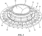
- FIG. 2 when assembled, the mounting element 12, adaptor 24, gimbal 24, and valve 44 are nested together to define a bore there through.
- the valve 44 is biased toward the closed position and the bore through the mounting element 12 is substantially occluded.
- the configuration shown in FIG. 2 is one representation of the mounting element 12 as it is affixed to tissue. In other configurations, the gimbal 28 may be tilted.
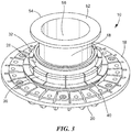
- the plug 48 is inserted into the interior of valve 44 with the distal end 58 of the plug 48 contacting the leaves 46 and urges them out of the closed position into the open position.
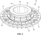
- FIG. 4 when the plug 48 is fully inserted, a substantially unobstructed opening through the mounting element 12 is established within the lumen 56 of the plug 48.
- the flange 52 on the plug 48 may contact the gimbal 26 to provide tactile feedback to the user that the plug is fully seated in the valve 44, and to arrest the advance of the plug.
- the distal end 58 of the plug 48 is flush or substantially flush with the distal side 20 of the ring 14.
- the plug 48 may further be friction fit within the bore of the mounting element 12.
- the plug 48 may be inserted through the valve 44 and into the bore defined mounting element 12.
- the mounting element 12 may be secured to the exterior surface of the heart. These steps can be performed in any order.
- the plug 48 may be inserted within the mounting element 12 before or after the mounting element 12 is affixed to the heart.
- a surgeon may make an incision through the wall of the heart, for example, by making a cruciate cut, through the lumen 56 of the plug 48.
- the surgeon may make the cruciate cut by hand (e.g. using a scalpel or similar cutting tool) or through the use of a cutting device 60 such as that disclosed in U.S. Patent Publication No. 2007/0167969 .
- the plug 48 urges the leaves 46 of the valve 44 into the open position, the plug 48 operates to protect the valve 44 from damage during formation of the cruciate cut.
- the plug 48 may be removed, thereby allowing the leaves 46 to transition back to their biased closed configuration.
- the leaves 46 substantially occlude the bore of the mounting element 12 to prevent blood or other material from flowing through the bore when in the closed configuration.
- a coring tool (not shown) such as that disclosed in pending U.S. Patent Publication No. 2009/012552 may then be inserted through the valve 44 to core the tissue and form a hole in the heart wall.
- the plug 48 may remain in place while the coring tool is used, if desired.
- the coring tool may have a rounded leading end such that it may be inserted through the valve 44 without the need for the plug 48.
- an MCSD can be connected to the heart through the hole in the heart wall.
- the pump of the MCSD or an inlet cannula connectable to the pump, may be inserted into the bore of the mounting element 12 and secured in place by the mounting element 12, for example, by the adaptor 24.
- the mounting element 12, valve 44, plug 48, a cutting device 60, and the coring tool may be included in a kit for providing access through tissue.
- the kit may also include an MCSD and although illustrated for use in the heart, may be used and configured for us with any organ or tissue in the body for insertion of an implant.
- the plug 48 may be carried on the cutting device 60 used to make the cruciate cut.
- the cutting device 60 may include a hollow plug 62 similar to the plug 48 discussed above, mounted on the distal end body of the cutting device 60 so that the plug 62 projects distal to the blade as the cutting device 60 is advanced into and through the mounting element 12.
- the plug 62 may force the valve 44 into an open position as the plug 62 is inserted into the bore of the mounting element 12, so that the lumen 56 of the plug 62 provides a clear path for movement of the blade associated with the cutting device 60 and formation of the cruciate cut.
- plug 62 may be slideably mounted on the body of the cutting device 60 and may be moved by, for example, an actuator on the cutting device 60 from a proximal position along the body of the cutting device 60 to a distal position on the body of the cutting device 60 which may force the leaves 46 into the open position.
- a mounting kit comprising a mounting element defining a bore, the mounting element being adapted for mounting to an exterior surface of an organ of a living subject; a one way valve adapted to be disposed in the bore of the mounting element, the one way valve substantially occluding the bore when the valve is in a closed position; a plug having an orifice extending therethrough, the plug being adapted to be releasably inserted into the one way valve, the plug holding the one way valve out of the closed position so that a portion of the exterior surface of the organ is accessible through the orifice in the plug when the mounting element is mounted on the exterior surface, the one way valve is disposed in the bore, and the plug is inserted in the one way valve.
- the mounting kit of Embodiment wherein the plug has a flange adapted to prevent over-insertion of the plug into the one way valve.
- the mounting kit of Embodiment 1 further comprising a coring tool.
- a method of creating an access way into tissue comprises placing a distal side of a mounting element adjacent an external surface of tissue wherein the mounting element defines a bore with a one way valve disposed therein and substantially occluding the bore when the valve is in a closed position; inserting a plug having an orifice extending therethrough into the one way valve, the plug holding the one way valve out of the closed position so that a portion of the exterior surface of the tissue is accessible through the orifice in the plug; and making a cut on the external surface of tissue through the orifice of the plug.
- Embodiment 6 wherein the one way valve is disposed in the bore prior to placing the mounting element adjacent the external surface of tissue.
- Embodiment 6 wherein the one way valve is disposed in the bore after placing the mounting element adjacent the external surface of tissue.
- Embodiment 6 further comprising removing the plug from the bore after making the cut.
- Embodiment 9 further comprising closing the one way valve by removing the plug from the bore.
- Embodiment 9 further comprising moving the one way valve out of the closed position with a coring tool.
- Embodiment 9 further comprising positioning a coring tool within the bore and coring the tissue.
- Embodiment 12 further comprising closing the one way valve by removing the coring tool.
- Embodiment 6 wherein the plug has a flange extending from a first end to prevent over-insertion of the plug into the one way valve.
Landscapes
- Health & Medical Sciences (AREA)
- Heart & Thoracic Surgery (AREA)
- Engineering & Computer Science (AREA)
- Cardiology (AREA)
- Life Sciences & Earth Sciences (AREA)
- Biomedical Technology (AREA)
- Veterinary Medicine (AREA)
- General Health & Medical Sciences (AREA)
- Public Health (AREA)
- Animal Behavior & Ethology (AREA)
- Hematology (AREA)
- Mechanical Engineering (AREA)
- Anesthesiology (AREA)
- Vascular Medicine (AREA)
- Transplantation (AREA)
- Oral & Maxillofacial Surgery (AREA)
- Surgery (AREA)
- Nuclear Medicine, Radiotherapy & Molecular Imaging (AREA)
- Orthopedic Medicine & Surgery (AREA)
- Medical Informatics (AREA)
- Molecular Biology (AREA)
- Prostheses (AREA)
- Surgical Instruments (AREA)
- External Artificial Organs (AREA)
Claims (12)
- Montagekit (10), Folgendes umfassend:ein Montageelement (12), das eine Bohrung definiert, wobei das Montageelement konfiguriert ist, um an einer Außenoberfläche eines Organs eines Patienten montieren werden;ein Einwegventil (44), das bemessen ist, um innerhalb der Bohrung des Montageelements aufgenommen und gehalten zu werden, wobei das Einwegventil eine geöffnete Position und eine geschlossene Position aufweist, wobei das Einwegventil die Bohrung im Wesentlichen verschließt, wenn sich das Ventil in der geschlossenen Position befindet, wobei das Einwegventil in der geschlossenen Position vorgespannt ist; undeinen Stopfen (48), der ein Lumen (56) aufweist, das sich dahindurch erstreckt, wobei der Stopfen konfiguriert ist, um durch wenigstens einen Abschnitt des Einwegventils lösbar eingeführt zu sein, wobei der Stopfen konfiguriert ist, um das Einwegventil von der geschlossenen Position in die geöffnete Position zu überführen und um das Einwegventil in der geöffneten Position beizubehalten, wenn der Stopfen innerhalb der Bohrung eingeführt wird,wobei, wenn der Stopfen vollständig eingeführt ist, ein distales Ende (58) des Stopfens mit einer distalen Seite des Montageelements bündig ist.
- Montagekit nach Anspruch 1, wobei der Stopfen einen Flansch (52) aufweist, der konfiguriert ist, um eine Einführung mit maximaler Tiefe des Stopfens innerhalb der Bohrung bereitzustellen.
- Montagekit nach Anspruch 1 oder 2, wobei das Einwegventil eines aus der Gruppe ist, die aus einem Dreiflügelventil, einem Klappenventil, einem Drosselventil und einem Entenschnabelventil besteht.
- Montagekit nach einem der Ansprüche 1-3, wobei das Montageelement einen Ring (14) beinhaltet, der einen Durchgang (16) definiert, wobei der Ring konfiguriert ist, um an der Außenoberfläche des Organs verankert zu sein.
- Montagekit nach einem der Ansprüche 1-4, wobei das Montageelement einen Adaptor (24) beinhaltet, der bemessen ist, um innerhalb des Ringdurchgangs aufgenommen zu werden, wobei der Adaptor einen Durchlass (38) definiert, wobei der Ringdurchgang im Wesentlichen koaxial ist, wenn dann der Adaptor innerhalb des Ringdurchgangs aufgenommen wird.
- Montagekit nach Anspruch 5, wobei der Adaptor eine ringförmige Wand (26) definiert, die mehrere Schlitze (30) definiert, und wobei wenigstens ein Abschnitt der ringförmigen Wand flexibel ist.
- Montagekit nach Anspruch 5 oder 6, wobei der Adaptor konfiguriert ist, um wenigstens eines aus der Gruppe aufzunehmen und zu halten, die aus einer Pumpe und einer Kanüle innerhalb der Bohrung besteht.
- Montagekit nach einem der Ansprüche 1-7, wobei das Montageelement ferner einen Kardanrahmen (28) beinhaltet, der bemessen ist, um innerhalb des Durchlasses des Adaptors aufgenommen und gehalten zu werden, wobei der Kardanrahmen eine Öffnung (41) definiert, wobei der Kardanrahmen konfiguriert ist, um die Ausrichtung hinsichtlich des Durchlasses des Adaptors zu kippen, wenn der Kardanrahmen innerhalb des Durchlasses des Adaptors aufgenommen wird.
- Montagekit nach Anspruch 8, wobei der Kardanrahmen im Wesentlichen zum Adaptor koaxial ist, wenn der Kardanrahmen innerhalb des Durchlasses des Adaptors aufgenommen wird.
- Montagekit nach einem der Ansprüche 8-9, wobei der Kardanrahmen eine die Öffnung umgebende Außenwand definiert und wobei wenigstens ein Abschnitt der Außenwand flexibel ist.
- Montagekit nach einem der Ansprüche 1-10, wobei das Organ das Herz ist.
- Montagekit nach einem der Ansprüche 1-11, wobei der Stopfen konfiguriert ist, um an einer Schneidvorrichtung (60) lösbar montiert zu werden.
Applications Claiming Priority (2)
| Application Number | Priority Date | Filing Date | Title |
|---|---|---|---|
| US201562269217P | 2015-12-18 | 2015-12-18 | |
| PCT/US2016/067219 WO2017106673A2 (en) | 2015-12-18 | 2016-12-16 | Hollow plug |
Publications (2)
| Publication Number | Publication Date |
|---|---|
| EP3389739A2 EP3389739A2 (de) | 2018-10-24 |
| EP3389739B1 true EP3389739B1 (de) | 2020-10-14 |
Family
ID=58191553
Family Applications (1)
| Application Number | Title | Priority Date | Filing Date |
|---|---|---|---|
| EP16840354.1A Active EP3389739B1 (de) | 2015-12-18 | 2016-12-16 | Hohldübel |
Country Status (4)
| Country | Link |
|---|---|
| US (1) | US10314956B2 (de) |
| EP (1) | EP3389739B1 (de) |
| CN (1) | CN108367108B (de) |
| WO (1) | WO2017106673A2 (de) |
Families Citing this family (4)
| Publication number | Priority date | Publication date | Assignee | Title |
|---|---|---|---|---|
| WO2017172738A1 (en) | 2016-03-30 | 2017-10-05 | Heartware, Inc. | Flanged heart tissue blocker |
| WO2019065943A1 (ja) | 2017-09-29 | 2019-04-04 | テルモ株式会社 | カテーテル組立体及び医療用弁 |
| JP7387717B2 (ja) | 2019-03-28 | 2023-11-28 | テルモ株式会社 | カテーテル組立体 |
| FR3103101A1 (fr) * | 2019-11-15 | 2021-05-21 | Fineheart | Dispositif d’ancrage d’une pompe cardiaque et ensemble de pose d’une pompe cardiaque équipé d’un tel dispositif d’ancrage |
Family Cites Families (10)
| Publication number | Priority date | Publication date | Assignee | Title |
|---|---|---|---|---|
| US6732501B2 (en) | 2002-06-26 | 2004-05-11 | Heartware, Inc. | Ventricular connector |
| US9744279B2 (en) * | 2005-12-08 | 2017-08-29 | Heartware, Inc. | Implant connector |
| US20070167969A1 (en) | 2006-01-13 | 2007-07-19 | Rajesh Pandey | Surgical cutting tool for making precise and accurate incisions |
| US10368899B2 (en) | 2006-01-13 | 2019-08-06 | Heartware, Inc. | Surgical tool for coring precise holes and providing for retrieval of tissue |
| US8870739B2 (en) | 2010-08-06 | 2014-10-28 | Heartware, Inc. | Conduit device for use with a ventricular assist device |
| CA2828885A1 (en) | 2011-03-02 | 2012-09-07 | Thoratec Corporation | Ventricular cuff |
| US9044236B2 (en) | 2011-05-18 | 2015-06-02 | Thoratec Corporation | Coring knife |
| JP6302992B2 (ja) * | 2013-03-15 | 2018-03-28 | エーピーケー アドバンスド メディカル テクノロジーズ,インコーポレイテッド | 組織壁に移植するためのコネクタ |
| EP3060271B1 (de) * | 2013-10-22 | 2018-09-12 | Heartware, Inc. | Verankerter montagering |
| WO2016070025A1 (en) * | 2014-10-31 | 2016-05-06 | Thoratec Corporation | Apical connectors and instruments for use in a heart wall |
-
2016
- 2016-12-16 US US15/381,777 patent/US10314956B2/en not_active Expired - Fee Related
- 2016-12-16 CN CN201680073628.1A patent/CN108367108B/zh not_active Expired - Fee Related
- 2016-12-16 EP EP16840354.1A patent/EP3389739B1/de active Active
- 2016-12-16 WO PCT/US2016/067219 patent/WO2017106673A2/en not_active Ceased
Non-Patent Citations (1)
| Title |
|---|
| None * |
Also Published As
| Publication number | Publication date |
|---|---|
| EP3389739A2 (de) | 2018-10-24 |
| WO2017106673A2 (en) | 2017-06-22 |
| US10314956B2 (en) | 2019-06-11 |
| US20170173236A1 (en) | 2017-06-22 |
| CN108367108A (zh) | 2018-08-03 |
| WO2017106673A3 (en) | 2017-08-31 |
| CN108367108B (zh) | 2020-09-08 |
Similar Documents
| Publication | Publication Date | Title |
|---|---|---|
| US9566146B2 (en) | Cardiovascular valve and valve housing apparatuses and systems | |
| EP2040639B1 (de) | Chirurgische werkzeuge für lvad-implantation | |
| EP2600918B1 (de) | Leitvorrichtung zur verwendung mit einem herzunterstützungssystem | |
| EP2747679B1 (de) | Vorrichtung zur herstellung eines vorübergehenden zugriffs und nachfolgende schliessung | |
| EP3060271B1 (de) | Verankerter montagering | |
| US20110260449A1 (en) | Apical access and control devices | |
| EP3975890B1 (de) | Zugangsvorrichtung für ein herz, abnehmbare hämostaseventileinheit und system mit einer herzunterstützungseinheit | |
| EP3389739B1 (de) | Hohldübel | |
| HK40070833A (en) | Access device for a heart | |
| HK40070832A (en) | System including a cardiac assist unit | |
| HK40070831A (en) | Removable hemostatic valve unit and system including a cardiac assist unit | |
| AU2013200266A1 (en) | Surgical tools for lvad implantation |
Legal Events
| Date | Code | Title | Description |
|---|---|---|---|
| STAA | Information on the status of an ep patent application or granted ep patent |
Free format text: STATUS: UNKNOWN |
|
| STAA | Information on the status of an ep patent application or granted ep patent |
Free format text: STATUS: THE INTERNATIONAL PUBLICATION HAS BEEN MADE |
|
| PUAI | Public reference made under article 153(3) epc to a published international application that has entered the european phase |
Free format text: ORIGINAL CODE: 0009012 |
|
| STAA | Information on the status of an ep patent application or granted ep patent |
Free format text: STATUS: REQUEST FOR EXAMINATION WAS MADE |
|
| 17P | Request for examination filed |
Effective date: 20180709 |
|
| AK | Designated contracting states |
Kind code of ref document: A2 Designated state(s): AL AT BE BG CH CY CZ DE DK EE ES FI FR GB GR HR HU IE IS IT LI LT LU LV MC MK MT NL NO PL PT RO RS SE SI SK SM TR |
|
| AX | Request for extension of the european patent |
Extension state: BA ME |
|
| DAV | Request for validation of the european patent (deleted) | ||
| DAX | Request for extension of the european patent (deleted) | ||
| GRAP | Despatch of communication of intention to grant a patent |
Free format text: ORIGINAL CODE: EPIDOSNIGR1 |
|
| STAA | Information on the status of an ep patent application or granted ep patent |
Free format text: STATUS: GRANT OF PATENT IS INTENDED |
|
| INTG | Intention to grant announced |
Effective date: 20200717 |
|
| GRAS | Grant fee paid |
Free format text: ORIGINAL CODE: EPIDOSNIGR3 |
|
| GRAA | (expected) grant |
Free format text: ORIGINAL CODE: 0009210 |
|
| STAA | Information on the status of an ep patent application or granted ep patent |
Free format text: STATUS: THE PATENT HAS BEEN GRANTED |
|
| AK | Designated contracting states |
Kind code of ref document: B1 Designated state(s): AL AT BE BG CH CY CZ DE DK EE ES FI FR GB GR HR HU IE IS IT LI LT LU LV MC MK MT NL NO PL PT RO RS SE SI SK SM TR |
|
| REG | Reference to a national code |
Ref country code: GB Ref legal event code: FG4D |
|
| REG | Reference to a national code |
Ref country code: AT Ref legal event code: REF Ref document number: 1322961 Country of ref document: AT Kind code of ref document: T Effective date: 20201015 Ref country code: CH Ref legal event code: EP |
|
| REG | Reference to a national code |
Ref country code: DE Ref legal event code: R096 Ref document number: 602016045996 Country of ref document: DE |
|
| REG | Reference to a national code |
Ref country code: IE Ref legal event code: FG4D |
|
| REG | Reference to a national code |
Ref country code: DE Ref legal event code: R079 Ref document number: 602016045996 Country of ref document: DE Free format text: PREVIOUS MAIN CLASS: A61M0001100000 Ipc: A61M0060000000 |
|
| REG | Reference to a national code |
Ref country code: AT Ref legal event code: MK05 Ref document number: 1322961 Country of ref document: AT Kind code of ref document: T Effective date: 20201014 |
|
| REG | Reference to a national code |
Ref country code: NL Ref legal event code: MP Effective date: 20201014 |
|
| PG25 | Lapsed in a contracting state [announced via postgrant information from national office to epo] |
Ref country code: FI Free format text: LAPSE BECAUSE OF FAILURE TO SUBMIT A TRANSLATION OF THE DESCRIPTION OR TO PAY THE FEE WITHIN THE PRESCRIBED TIME-LIMIT Effective date: 20201014 Ref country code: GR Free format text: LAPSE BECAUSE OF FAILURE TO SUBMIT A TRANSLATION OF THE DESCRIPTION OR TO PAY THE FEE WITHIN THE PRESCRIBED TIME-LIMIT Effective date: 20210115 Ref country code: PT Free format text: LAPSE BECAUSE OF FAILURE TO SUBMIT A TRANSLATION OF THE DESCRIPTION OR TO PAY THE FEE WITHIN THE PRESCRIBED TIME-LIMIT Effective date: 20210215 Ref country code: RS Free format text: LAPSE BECAUSE OF FAILURE TO SUBMIT A TRANSLATION OF THE DESCRIPTION OR TO PAY THE FEE WITHIN THE PRESCRIBED TIME-LIMIT Effective date: 20201014 Ref country code: NO Free format text: LAPSE BECAUSE OF FAILURE TO SUBMIT A TRANSLATION OF THE DESCRIPTION OR TO PAY THE FEE WITHIN THE PRESCRIBED TIME-LIMIT Effective date: 20210114 |
|
| REG | Reference to a national code |
Ref country code: LT Ref legal event code: MG4D |
|
| PG25 | Lapsed in a contracting state [announced via postgrant information from national office to epo] |
Ref country code: SE Free format text: LAPSE BECAUSE OF FAILURE TO SUBMIT A TRANSLATION OF THE DESCRIPTION OR TO PAY THE FEE WITHIN THE PRESCRIBED TIME-LIMIT Effective date: 20201014 Ref country code: ES Free format text: LAPSE BECAUSE OF FAILURE TO SUBMIT A TRANSLATION OF THE DESCRIPTION OR TO PAY THE FEE WITHIN THE PRESCRIBED TIME-LIMIT Effective date: 20201014 Ref country code: AT Free format text: LAPSE BECAUSE OF FAILURE TO SUBMIT A TRANSLATION OF THE DESCRIPTION OR TO PAY THE FEE WITHIN THE PRESCRIBED TIME-LIMIT Effective date: 20201014 Ref country code: BG Free format text: LAPSE BECAUSE OF FAILURE TO SUBMIT A TRANSLATION OF THE DESCRIPTION OR TO PAY THE FEE WITHIN THE PRESCRIBED TIME-LIMIT Effective date: 20210114 Ref country code: IS Free format text: LAPSE BECAUSE OF FAILURE TO SUBMIT A TRANSLATION OF THE DESCRIPTION OR TO PAY THE FEE WITHIN THE PRESCRIBED TIME-LIMIT Effective date: 20210214 Ref country code: LV Free format text: LAPSE BECAUSE OF FAILURE TO SUBMIT A TRANSLATION OF THE DESCRIPTION OR TO PAY THE FEE WITHIN THE PRESCRIBED TIME-LIMIT Effective date: 20201014 Ref country code: PL Free format text: LAPSE BECAUSE OF FAILURE TO SUBMIT A TRANSLATION OF THE DESCRIPTION OR TO PAY THE FEE WITHIN THE PRESCRIBED TIME-LIMIT Effective date: 20201014 |
|
| PG25 | Lapsed in a contracting state [announced via postgrant information from national office to epo] |
Ref country code: NL Free format text: LAPSE BECAUSE OF FAILURE TO SUBMIT A TRANSLATION OF THE DESCRIPTION OR TO PAY THE FEE WITHIN THE PRESCRIBED TIME-LIMIT Effective date: 20201014 Ref country code: HR Free format text: LAPSE BECAUSE OF FAILURE TO SUBMIT A TRANSLATION OF THE DESCRIPTION OR TO PAY THE FEE WITHIN THE PRESCRIBED TIME-LIMIT Effective date: 20201014 |
|
| REG | Reference to a national code |
Ref country code: DE Ref legal event code: R097 Ref document number: 602016045996 Country of ref document: DE |
|
| PG25 | Lapsed in a contracting state [announced via postgrant information from national office to epo] |
Ref country code: CZ Free format text: LAPSE BECAUSE OF FAILURE TO SUBMIT A TRANSLATION OF THE DESCRIPTION OR TO PAY THE FEE WITHIN THE PRESCRIBED TIME-LIMIT Effective date: 20201014 Ref country code: EE Free format text: LAPSE BECAUSE OF FAILURE TO SUBMIT A TRANSLATION OF THE DESCRIPTION OR TO PAY THE FEE WITHIN THE PRESCRIBED TIME-LIMIT Effective date: 20201014 Ref country code: LT Free format text: LAPSE BECAUSE OF FAILURE TO SUBMIT A TRANSLATION OF THE DESCRIPTION OR TO PAY THE FEE WITHIN THE PRESCRIBED TIME-LIMIT Effective date: 20201014 Ref country code: SM Free format text: LAPSE BECAUSE OF FAILURE TO SUBMIT A TRANSLATION OF THE DESCRIPTION OR TO PAY THE FEE WITHIN THE PRESCRIBED TIME-LIMIT Effective date: 20201014 Ref country code: SK Free format text: LAPSE BECAUSE OF FAILURE TO SUBMIT A TRANSLATION OF THE DESCRIPTION OR TO PAY THE FEE WITHIN THE PRESCRIBED TIME-LIMIT Effective date: 20201014 Ref country code: RO Free format text: LAPSE BECAUSE OF FAILURE TO SUBMIT A TRANSLATION OF THE DESCRIPTION OR TO PAY THE FEE WITHIN THE PRESCRIBED TIME-LIMIT Effective date: 20201014 |
|
| REG | Reference to a national code |
Ref country code: CH Ref legal event code: PL |
|
| PLBE | No opposition filed within time limit |
Free format text: ORIGINAL CODE: 0009261 |
|
| STAA | Information on the status of an ep patent application or granted ep patent |
Free format text: STATUS: NO OPPOSITION FILED WITHIN TIME LIMIT |
|
| PG25 | Lapsed in a contracting state [announced via postgrant information from national office to epo] |
Ref country code: MC Free format text: LAPSE BECAUSE OF FAILURE TO SUBMIT A TRANSLATION OF THE DESCRIPTION OR TO PAY THE FEE WITHIN THE PRESCRIBED TIME-LIMIT Effective date: 20201014 Ref country code: DK Free format text: LAPSE BECAUSE OF FAILURE TO SUBMIT A TRANSLATION OF THE DESCRIPTION OR TO PAY THE FEE WITHIN THE PRESCRIBED TIME-LIMIT Effective date: 20201014 |
|
| REG | Reference to a national code |
Ref country code: BE Ref legal event code: MM Effective date: 20201231 |
|
| 26N | No opposition filed |
Effective date: 20210715 |
|
| GBPC | Gb: european patent ceased through non-payment of renewal fee |
Effective date: 20210114 |
|
| PG25 | Lapsed in a contracting state [announced via postgrant information from national office to epo] |
Ref country code: AL Free format text: LAPSE BECAUSE OF FAILURE TO SUBMIT A TRANSLATION OF THE DESCRIPTION OR TO PAY THE FEE WITHIN THE PRESCRIBED TIME-LIMIT Effective date: 20201014 Ref country code: IE Free format text: LAPSE BECAUSE OF NON-PAYMENT OF DUE FEES Effective date: 20201216 Ref country code: LU Free format text: LAPSE BECAUSE OF NON-PAYMENT OF DUE FEES Effective date: 20201216 Ref country code: IT Free format text: LAPSE BECAUSE OF FAILURE TO SUBMIT A TRANSLATION OF THE DESCRIPTION OR TO PAY THE FEE WITHIN THE PRESCRIBED TIME-LIMIT Effective date: 20201014 |
|
| PG25 | Lapsed in a contracting state [announced via postgrant information from national office to epo] |
Ref country code: LI Free format text: LAPSE BECAUSE OF NON-PAYMENT OF DUE FEES Effective date: 20201231 Ref country code: GB Free format text: LAPSE BECAUSE OF NON-PAYMENT OF DUE FEES Effective date: 20210114 Ref country code: CH Free format text: LAPSE BECAUSE OF NON-PAYMENT OF DUE FEES Effective date: 20201231 Ref country code: SI Free format text: LAPSE BECAUSE OF FAILURE TO SUBMIT A TRANSLATION OF THE DESCRIPTION OR TO PAY THE FEE WITHIN THE PRESCRIBED TIME-LIMIT Effective date: 20201014 |
|
| PG25 | Lapsed in a contracting state [announced via postgrant information from national office to epo] |
Ref country code: IS Free format text: LAPSE BECAUSE OF FAILURE TO SUBMIT A TRANSLATION OF THE DESCRIPTION OR TO PAY THE FEE WITHIN THE PRESCRIBED TIME-LIMIT Effective date: 20210214 Ref country code: TR Free format text: LAPSE BECAUSE OF FAILURE TO SUBMIT A TRANSLATION OF THE DESCRIPTION OR TO PAY THE FEE WITHIN THE PRESCRIBED TIME-LIMIT Effective date: 20201014 Ref country code: MT Free format text: LAPSE BECAUSE OF FAILURE TO SUBMIT A TRANSLATION OF THE DESCRIPTION OR TO PAY THE FEE WITHIN THE PRESCRIBED TIME-LIMIT Effective date: 20201014 Ref country code: CY Free format text: LAPSE BECAUSE OF FAILURE TO SUBMIT A TRANSLATION OF THE DESCRIPTION OR TO PAY THE FEE WITHIN THE PRESCRIBED TIME-LIMIT Effective date: 20201014 |
|
| PG25 | Lapsed in a contracting state [announced via postgrant information from national office to epo] |
Ref country code: MK Free format text: LAPSE BECAUSE OF FAILURE TO SUBMIT A TRANSLATION OF THE DESCRIPTION OR TO PAY THE FEE WITHIN THE PRESCRIBED TIME-LIMIT Effective date: 20201014 |
|
| PG25 | Lapsed in a contracting state [announced via postgrant information from national office to epo] |
Ref country code: BE Free format text: LAPSE BECAUSE OF NON-PAYMENT OF DUE FEES Effective date: 20201231 |
|
| PGFP | Annual fee paid to national office [announced via postgrant information from national office to epo] |
Ref country code: FR Payment date: 20221122 Year of fee payment: 7 |
|
| PG25 | Lapsed in a contracting state [announced via postgrant information from national office to epo] |
Ref country code: FR Free format text: LAPSE BECAUSE OF NON-PAYMENT OF DUE FEES Effective date: 20231231 |
|
| PG25 | Lapsed in a contracting state [announced via postgrant information from national office to epo] |
Ref country code: FR Free format text: LAPSE BECAUSE OF NON-PAYMENT OF DUE FEES Effective date: 20231231 |
|
| PGFP | Annual fee paid to national office [announced via postgrant information from national office to epo] |
Ref country code: DE Payment date: 20251126 Year of fee payment: 10 |