EP3389459B1 - Shower enclosure header - Google Patents
Shower enclosure header Download PDFInfo
- Publication number
- EP3389459B1 EP3389459B1 EP16876792.9A EP16876792A EP3389459B1 EP 3389459 B1 EP3389459 B1 EP 3389459B1 EP 16876792 A EP16876792 A EP 16876792A EP 3389459 B1 EP3389459 B1 EP 3389459B1
- Authority
- EP
- European Patent Office
- Prior art keywords
- header
- anchor
- channel
- glass
- header member
- Prior art date
- Legal status (The legal status is an assumption and is not a legal conclusion. Google has not performed a legal analysis and makes no representation as to the accuracy of the status listed.)
- Active
Links
- 239000011521 glass Substances 0.000 claims description 51
- 238000005304 joining Methods 0.000 claims description 29
- 238000000034 method Methods 0.000 claims description 8
- 230000008878 coupling Effects 0.000 claims description 3
- 238000010168 coupling process Methods 0.000 claims description 3
- 238000005859 coupling reaction Methods 0.000 claims description 3
- 230000001154 acute effect Effects 0.000 claims description 2
- 230000013011 mating Effects 0.000 claims description 2
- 229920000515 polycarbonate Polymers 0.000 claims description 2
- 239000004417 polycarbonate Substances 0.000 claims description 2
- 230000014759 maintenance of location Effects 0.000 description 5
- 238000004381 surface treatment Methods 0.000 description 5
- 125000000391 vinyl group Chemical group [H]C([*])=C([H])[H] 0.000 description 5
- 229920002554 vinyl polymer Polymers 0.000 description 5
- 230000007246 mechanism Effects 0.000 description 4
- 229910052782 aluminium Inorganic materials 0.000 description 3
- XAGFODPZIPBFFR-UHFFFAOYSA-N aluminium Chemical compound [Al] XAGFODPZIPBFFR-UHFFFAOYSA-N 0.000 description 3
- 239000000945 filler Substances 0.000 description 3
- 238000011900 installation process Methods 0.000 description 3
- 239000000463 material Substances 0.000 description 3
- 230000000712 assembly Effects 0.000 description 2
- 238000000429 assembly Methods 0.000 description 2
- 230000006835 compression Effects 0.000 description 2
- 238000007906 compression Methods 0.000 description 2
- 238000005553 drilling Methods 0.000 description 2
- 229910052751 metal Inorganic materials 0.000 description 2
- 239000002184 metal Substances 0.000 description 2
- 238000012986 modification Methods 0.000 description 2
- 230000004048 modification Effects 0.000 description 2
- 230000008901 benefit Effects 0.000 description 1
- 230000008859 change Effects 0.000 description 1
- 238000010276 construction Methods 0.000 description 1
- 238000005520 cutting process Methods 0.000 description 1
- 230000001419 dependent effect Effects 0.000 description 1
- 229940108890 emend Drugs 0.000 description 1
- 238000003780 insertion Methods 0.000 description 1
- 230000037431 insertion Effects 0.000 description 1
- 238000009434 installation Methods 0.000 description 1
- 230000002452 interceptive effect Effects 0.000 description 1
- 238000011031 large-scale manufacturing process Methods 0.000 description 1
- 230000036961 partial effect Effects 0.000 description 1
- 230000000135 prohibitive effect Effects 0.000 description 1
- 230000009467 reduction Effects 0.000 description 1
- 230000002829 reductive effect Effects 0.000 description 1
- 230000000717 retained effect Effects 0.000 description 1
- 230000003319 supportive effect Effects 0.000 description 1
Images


Classifications
-
- E—FIXED CONSTRUCTIONS
- E04—BUILDING
- E04C—STRUCTURAL ELEMENTS; BUILDING MATERIALS
- E04C3/00—Structural elongated elements designed for load-supporting
- E04C3/02—Joists; Girders, trusses, or trusslike structures, e.g. prefabricated; Lintels; Transoms; Braces
- E04C3/28—Joists; Girders, trusses, or trusslike structures, e.g. prefabricated; Lintels; Transoms; Braces of materials not covered by groups E04C3/04 - E04C3/20
-
- A—HUMAN NECESSITIES
- A47—FURNITURE; DOMESTIC ARTICLES OR APPLIANCES; COFFEE MILLS; SPICE MILLS; SUCTION CLEANERS IN GENERAL
- A47K—SANITARY EQUIPMENT NOT OTHERWISE PROVIDED FOR; TOILET ACCESSORIES
- A47K3/00—Baths; Douches; Appurtenances therefor
- A47K3/28—Showers or bathing douches
- A47K3/30—Screens or collapsible cabinets for showers or baths
-
- A—HUMAN NECESSITIES
- A47—FURNITURE; DOMESTIC ARTICLES OR APPLIANCES; COFFEE MILLS; SPICE MILLS; SUCTION CLEANERS IN GENERAL
- A47K—SANITARY EQUIPMENT NOT OTHERWISE PROVIDED FOR; TOILET ACCESSORIES
- A47K3/00—Baths; Douches; Appurtenances therefor
- A47K3/28—Showers or bathing douches
- A47K3/283—Fixed showers
Definitions
- the present invention relates to glass enclosures such as showers and more particularly to an improved header for such enclosures.
- a stiffening header is utilized along the full length and upper sides of the top edge of the enclosure.
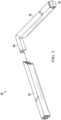
- a header 10 is shown in a prior art Figure 1 in an exploded view, along with related items.
- the header 10 is made of extruded aluminum that is color treated to match the hinge and handle hardware that is utilized on the shower door.
- the header typically includes a longitudinal (i.e., along its length) channel 12 that is typically 1/2 inch wide and is for receiving the edge of the glass, as well as stiffening members 14 and 16, where the stiffening members 14 are slightly longer than the stiffening members 16, that protrude 90 degrees from the header inner walls into the channel 12, so as to cooperate with vinyl seals 18 that are later placed between each upper side of the glass and the stiffening members.
- the header 10 is placed over the top edge of the glass and secured to the glass by the use of the continuous length vinyl seals 18 that are forcibly inserted on each side of the glass, so as to fit between the glass and the stiffening members 14 and 16.
- a screw hole is drilled from above the header at a location near the end of where that header meets the shower wall, at a 45-degree downward angle, through the top edge and into the shower wall.
- a typical header may be 1 1/8" tall, so there is some clearance ( e . g ., 3/8") above the glass once it is inserted into the channel 12, thereby providing clearance also so that the screw may be located through the hole in the top of the header and into the wall, without interfering with the top of the glass in the channel.
- the screw length as it passes through the header and into the wall is co-planar with the plane of the glass below it.
- the above steps are typically a two person operation, as one person is required to hold the pane of glass in position, while the other positions the header atop the glass (typically also requiring a ladder to be at or even above the glass height), and then drills the 45 degree angle hole through the header top and into the shower wall surface, including any treatment on that wall (e.g., tile).
- a screw is then threaded through the header 10 and into the wall, where the screw may be secured snuggly into the tile with the screw entering a typical wall anchor that is located in the hole previously drilled from atop the header 10.
- the final step in the header installation process is the insertion of a snap filler 20 that is snapped into the channel over the location of the door, typically so as to fill the channel 12 above the door so as to block it from sight, such as from an angle or perspective below the header looking up at it, from either side of the door.
- a snap filler 20 that is snapped into the channel over the location of the door, typically so as to fill the channel 12 above the door so as to block it from sight, such as from an angle or perspective below the header looking up at it, from either side of the door.
- the prior art also includes an insert 22 that fits within a shelf 24 along the top of the header, that is, two pieces of header are cut at angles (e.g., 45 degrees) so as to join together to combine the desired corner angle, and the inset 22 is then placed within the shelf 24 of each header piece, as the respective angled ends of each of the two header pieces are brought together so as to capture the insert 22 between both pieces.
- US 2004/159049 discloses a shower door system with a compression mounting system including a horizontal header and curb and upright jambs.
- the header and curb each include one or more rails mounted above and below the door via associated expansion assemblies. These assemblies have threaded shafts that engage one or more nuts mounted to the rails such that turning the shafts applies compressive forces against opposing end walls of a shower enclosure.
- FR 2 277 963 discloses a window frame for sliding windows, the window frame comprising two uprights and two crosspieces connected together by brackets.
- the brackets comprise plates which are arranged to fit into cavities in the uprights and crosspieces.
- the window frame defines two sliding zones which hold two movable counter frames which carry the glass panes.
- the preferred embodiment provides a header system for use with glass panels, as preferably implemented to create a shower enclosure.
- the preferred embodiment header system 30 includes header members 32 that work in conjunction with an end piece wall anchor 34 and, when multiple glass panels are to be installed that are not co-planar, also an angle joining member 36.
- Each header member 32 is preferably 1 inch wide and 7/8 inch tall, where the latter dimension may be contrasted with a typical prior art metallic header that is 1 1/8 inch tall, so the preferred embodiment is preferable to various consumers as the profile reduction is appealing.
- each header member 32 is determined to approximately match the length of the edge of glass to which the header member 32 will attach, such to some variation for any corner as well as mating with the end piece wall anchor 34, as discussed below. Still further, in a preferred embodiment the material(s) of header member 32 may be something other than metal as, indeed, metal can unnecessarily increase costs, particularly in view of increased costs, such as tariffs, that are otherwise associated with certain imported extruded aluminum; hence, in this regard and others, a preferred embodiment material for members 32 is coated polycarbonate. Lastly, each header member 32 is preferably color coated to match the hardware used in combination with a shower system, that is, with the glass that is held in place in part by header system 30.
- Figure 2 illustrates the system 30 in partial assembly
- Figure 3 illustrates parts of the system 30 separated from one another, with both a front and rear perspective of the end piece wall anchor 34.
- an end piece wall anchor 34 is installed onto a wall where the shower is to be formed, by securing a fastener ( e . g ., screw) through the hole 38 at an endwall of the wall anchor 34.
- a fastener e . g ., screw
- endwall of the wall anchor 34 is generally perpendicular to the length of the rest of the anchor 34, so the wall anchor 34 endwall can be placed against the shower wall, and a marking made through the hole 38, or a drill bit may be passed directly through the hole 38; hence, the screw through hole 38, and any preceding pilot hole, if desired, is drilled and located at a 90 (or approximately, such as within 15 degrees thereof) degree angle relative to the shower wall, that is, an angle much closer to 90 degrees as compared to the 45 degree angle required in the prior art; thus, the preferred embodiment provides a much easier and less error-prone drilling procedure as compared to the prior art, and it also eliminates the need for a ladder, as the drilling is accomplished first to install the end piece wall anchor 34, before the glass is in place and without the need to be above the top horizontal edge of the glass.
- an outer surface of wall anchor 34 also includes a mechanism, such as a friction fitting retention surface, as may be implemented with an inclined surface treatment as detailed later, whereby once the header member 32 is slid over the wall anchor 34, there is resistance to pulling the two items back apart.
- a second header member 32 may be adjoined a first one, through use of an angle joining member 36, which for illustration is shown as a 90 degree member, and whereby each header member 32 has an angled cut at its end (e.g., with a 45 degree miter edge to each member) so as to create a total of n abutting 90 degree completed junction where the two pieces come together.
- an angle joining member 36 which for illustration is shown as a 90 degree member, and whereby each header member 32 has an angled cut at its end (e.g., with a 45 degree miter edge to each member) so as to create a total of n abutting 90 degree completed junction where the two pieces come together.
- both ends of the angle joining member 36 also include a friction fitting retention surface, such as an inclined surface treatment, whereby once the header member 32 is slid over each end of the angle joining member 36, there is resistance to pulling the two items back apart.
- Figure 2 illustrates a 90 degree coupling between two header members 32 via an angle joining member 36
- other angles are contemplated other than 90 degrees, although such adjustments, particularly in large bulk numbers as would be expected for large scale production and marketability, may prove to be time and cost prohibitive, but also would nonetheless require cutting corresponding angled edges of the header members 32 to match the non-90 degree angle of such a member 36. Additional illustrations of these and other variations of these aspects are further explored below.
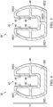
- Figure 4 illustrates a cross-sectional end view of a header member 32, as may further demonstrate aspects introduced above. From the illustrated view, the channel 42 in the header member 32 is clearly visible, and preferably it is considerably narrower than that of the prior art, where the prior art is typically 1/2 inch and the preferred embodiment width of the channel 42 is 1/4 inch. Also visible in the view of Figure 4 are that preferred embodiment header member further includes paired angled stiffening members 44 and 46, extending inward approximately 1/16 inch and at an acute upward angle relative to the inner walls and point of entry of the glass into the channel 42, where stiffening members 44 and 46 preferably extend along the inner walls of the channel 42 and parallel to the entire length of the header member 32.
- stiffening members 44 and 46 are integral to, and molded into, the header member channel 42 and are of a different density as to be flexible so as to accept the glass into the channel and abutting the stiffening members 44 and 46.
- these stiffening members 44 and 46 are for gripping the glass firmly when the glass edge and upper sides are positioned in the channel 42, thereby eliminating the prior art need for vinyl seals and also permitting the channel 42 to be relatively narrower than the prior art, as the latter also must accommodate the additional vinyl seals.
- a shelf 48 is shown as a member that approximately bisects the overall height HT (e.g., 7/8 inch) of the header member 32, although the shelf 48 does not extend within the channel 42, yet is approximately 15/16 inch wide. Shelf 48 thereby defines a first set of cavities 50C and a second set of cavities 52C, where in the example of Figure 4 the first set of cavities 50C includes two cavities 50C1 and 50C2 and the second set of cavities 52C includes a single cavity.
- the cavities 50C and 52C provide respective receiving areas for receiving the ends of the end piece wall anchor 34 - specifically, returning to Figure 3 and the depiction of the end piece wall anchor 34 to the right, note that it has prongs 50P1, 50P2, and 52P, where the numbers of "50” and "52" in both Figures 3 and 4 illustrate the correspondence that the end piece wall anchor 34 of Figure 3 mates to the header member 32 of Figure 4 , with the prongs 50P1 and 50P2 fitting into the cavities 50C1 and 50C2, respectively, and the prong 52P fitting into the cavity 52C.
- the header member 32 is slid into an abutting and enveloping relationship with the anchor 34, as shown in Figure 2 , while at the same time both the channel 42 under the header member 32 and the channel 40 of the end piece wall anchor 34 are aligned along the sides of the upper edge of the glass.
- two pieces of the header member 32 may be brought together to form a corner (or other non-90 degree joint) above two pieces of glass abutting in a non-planar fashion, and note now that such an angle joining member 36 also fits relative to the shelf 48 of the header member 32.
- the narrower channel 42 of the preferred embodiment there is a reduced aesthetic need to include a channel snap filler above the shower door, also as a benefit as compared to the prior art.
- Figure 5 illustrates a cross-sectional end view of an alternative preferred embodiment header member 32', as compared to header member 32 shown in Figure 4 .
- member 32' it includes an additional cavity divider 52CD.
- cavity divider 52CD extends along a majority, or the entirety, of the length and on the interior of member 32.
- the second cavity set 52C includes a single cavity in Figure 4
- cavity divider 52CD divides the second cavity set 52C from Figure 5 into two different cavities, shown in Figure 5 as cavities 52C1 and 52C2.
- cavity divider 52CD is preferable in some or many implementations, as it provides additional structural support to member 32, particularly for lengthy runs, so that the member 32 does not twist or otherwise distort in shape as it spans along the edge of a piece of glass.
- cavity divider 52CD in this alternatives preferred embodiment modifications are also made to anchor member 34 and angle joining member 36, so as to facilitate the same slidable (and preferably corresponding) friction fit relationships described above, so as to accommodate the presence of cavity divider 52CD.
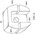
- Figure 6 illustrates a perspective view of an alternative preferred embodiment anchor 34', so as to cooperate with the alternative preferred embodiment header member 32' of Figure 5 .
- anchor 34' it includes two prongs 52P1 and 52P2, so as to friction fit within respective cavities 52C1 and 52C2, shown in Figure 5 .
- prongs 52P1 and 52P2 are separated by a gap 52G that thereby accommodates the cavity divider 52CD of anchor 34' (see Figure 5 ).
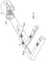
- FIG. 7 illustrates a perspective view of the alternative preferred embodiment header member 32' shown in cross-sectional view in Figure 5 , along with three angle joining members 36 52P2 , 36 50P1 , and 36 50P2 , partially inserted into the end of respective cavities of header member 32'.
- each angle joining member has a change in angle so as to facilitate the attachment of two header members as described earlier, where again in the example of Figure 7 the angle is 90 degrees.
- each angle joining member is fit into a cavity in one header member, after which the opposing end of each angle joining member is fit into a cavity in another header member, whereby each header member is slid to fully cover from visibility the angle member and to bring one header member into abutment with the other header member, so as to form a corner or other angle that matches the glass that is, or will be, fitted below each of the two header members.
- Figure 7 illustrates three angle joining members 36 52P2 , 36 50P1 , and 36 50P2 , by way of example, so as to not unduly obscure the perspective view. However, in actual assembly, four such angle joining members may be used.
- assembly method it may be plausible to use only two such angle joining members, thereby filling only two cavities near the emend of the two header members to be abutted to one another, while leaving the remaining two cavities of each abutting header member vacant; indeed, further in this regard, it is contemplated that use of two joining members in this regard will be sufficiently supportive for structural integrity, while reducing the number of parts (and associated labor) in joining header members to an angle.
- joining members when only two such joining members are used in this method, it is further preferably that they are in non-adjacent cavities, for example, by putting one in the upper left cavity and the other in the lower right cavity while leaving the upper right cavity and lower left cavity vacant, or alternatively by putting one in the upper right cavity and the other in the lower left cavity while leaving the upper left cavity and lower right cavity vacant.
- FIG 8 illustrates an exploded view of the alternative preferred embodiment header member 32' shown in Figure 7 , along with two angle joining members 36 52P1 and 36 52P2 .
- the exploded view further demonstrates how an end of each of the angle joining members 36 52P1 and 36 52P2 is for inserting into a respective cavity 52P1 and 52P2.
- each angle joining members 36 52P1 and 36 52P2 also preferably included a mechanism 54, for example a friction fitting retention surface treatment or structure, where in the illustrated example the surface includes an inclined base that increases in height and from which a number of teeth members are formed, relative to the upper surface of the joining member, and in a direction away from the end of the joining member to be inserted into a respective cavity.
- a mechanism 54 for example a friction fitting retention surface treatment or structure, where in the illustrated example the surface includes an inclined base that increases in height and from which a number of teeth members are formed, relative to the upper surface of the joining member, and in a direction away from the end of the joining member to be inserted into
- the preferred embodiments provide an improved glass header system.
- the preferred embodiment materials and configuration allow both a simplified and quick construction of generally vertical standing glass panes, retained in place in part by a header system as described.
- the installation process is sped up dramatically, the misalignment of glass panels is eliminated, extraneous noises are eliminated and multiple pieces are eliminated, further speeding up the installation process and reducing costs.
- inventive scope has been demonstrated by certain preferred embodiments, one skilled in the art will appreciate that it may be further subject to various modifications within the scope defined by the wording of the appended claims.
Description
- The present invention relates to glass enclosures such as showers and more particularly to an improved header for such enclosures.
- Traditionally, when installing a glass shower enclosure consisting of, for example ¼" thickness glass or less, a stiffening header is utilized along the full length and upper sides of the top edge of the enclosure. Such a
header 10 is shown in a prior artFigure 1 in an exploded view, along with related items. Theheader 10 is made of extruded aluminum that is color treated to match the hinge and handle hardware that is utilized on the shower door. The header typically includes a longitudinal (i.e., along its length)channel 12 that is typically 1/2 inch wide and is for receiving the edge of the glass, as well asstiffening members stiffening members 14 are slightly longer than thestiffening members 16, that protrude 90 degrees from the header inner walls into thechannel 12, so as to cooperate withvinyl seals 18 that are later placed between each upper side of the glass and the stiffening members. When installing theheader 10, theheader 10 is placed over the top edge of the glass and secured to the glass by the use of the continuouslength vinyl seals 18 that are forcibly inserted on each side of the glass, so as to fit between the glass and thestiffening members channel 12, thereby providing clearance also so that the screw may be located through the hole in the top of the header and into the wall, without interfering with the top of the glass in the channel. Hence, the screw length as it passes through the header and into the wall is co-planar with the plane of the glass below it. Note also that the above steps are typically a two person operation, as one person is required to hold the pane of glass in position, while the other positions the header atop the glass (typically also requiring a ladder to be at or even above the glass height), and then drills the 45 degree angle hole through the header top and into the shower wall surface, including any treatment on that wall (e.g., tile). A screw is then threaded through theheader 10 and into the wall, where the screw may be secured snuggly into the tile with the screw entering a typical wall anchor that is located in the hole previously drilled from atop theheader 10. The final step in the header installation process is the insertion of asnap filler 20 that is snapped into the channel over the location of the door, typically so as to fill thechannel 12 above the door so as to block it from sight, such as from an angle or perspective below the header looking up at it, from either side of the door. Lastly, note that to create corners (e.g., 90 degrees), the prior art also includes an insert 22 that fits within ashelf 24 along the top of the header, that is, two pieces of header are cut at angles (e.g., 45 degrees) so as to join together to combine the desired corner angle, and the inset 22 is then placed within theshelf 24 of each header piece, as the respective angled ends of each of the two header pieces are brought together so as to capture the insert 22 between both pieces. - There are a number of issues related to the aluminum header and its installation procedure that are problematic. The following are examples: (1) inserting the vinyl will misalign the glass panels; (2) the holes drilled at an angle through the header and into the wall, for mounting via a diagonally-positioned screw, cause tile issues and are very difficult to achieve; (3) a ladder is required to properly install the diagonal screws; and (4) the snap filler creates metallic noises as the door is opened and closed. Thus, while the above approach has been used extensively and with some level of success in the glass shower industry, the present inventor has recognized long felt but unresolved drawbacks with the prior art approach, and such issues are improved with the preferred embodiments, described below.
-
US 2004/159049 discloses a shower door system with a compression mounting system including a horizontal header and curb and upright jambs. The header and curb each include one or more rails mounted above and below the door via associated expansion assemblies. These assemblies have threaded shafts that engage one or more nuts mounted to the rails such that turning the shafts applies compressive forces against opposing end walls of a shower enclosure. -
FR 2 277 963 - According to one aspect of the present invention there is provided apparatus for retaining a glass panel as defined in
claim 1. - According to another aspect of the present invention there is provided a method for retaining a glass panel as defined in
claim 12. - Preferred features of the invention are recited in the dependent claims.
- The preferred embodiments will be described in detail below by referring to the accompanying drawings:
-
Figure 1 illustrates an exploded view of aprior art header 10, along with related items. -
Figure 2 illustrates a preferred embodiment header system, includingheader members 32 that work in conjunction with an endpiece wall anchor 34 and anangle joining member 36. -
Figure 3 illustrates parts of the system ofFigure 2 separated from one another, with both a front and rear perspective of the endpiece wall anchor 34. -
Figure 4 illustrates a cross-sectional end view of aheader member 32. -
Figure 5 illustrates a cross-sectional end view of an alternative preferred embodiment header member 32'. -
Figure 6 illustrates a perspective view of an alternative preferred embodiment anchor 34'. -
Figure 7 illustrates a perspective view of the alternative preferred embodiment header member 32' shown in cross-sectional view inFigure 5 . -
Figure 8 illustrates an exploded view of the alternative preferred embodiment header member 32' shown inFigure 7 . -
Figure 1 was described above in the Background of the Invention section of this document and the reader is assumed to be familiar with that discussion. - The preferred embodiment provides a header system for use with glass panels, as preferably implemented to create a shower enclosure. As shown in
Figures 2 and3 , the preferredembodiment header system 30 includesheader members 32 that work in conjunction with an endpiece wall anchor 34 and, when multiple glass panels are to be installed that are not co-planar, also anangle joining member 36. Eachheader member 32 is preferably 1 inch wide and 7/8 inch tall, where the latter dimension may be contrasted with a typical prior art metallic header that is 1 1/8 inch tall, so the preferred embodiment is preferable to various consumers as the profile reduction is appealing. Further, the length of eachheader member 32 is determined to approximately match the length of the edge of glass to which theheader member 32 will attach, such to some variation for any corner as well as mating with the endpiece wall anchor 34, as discussed below. Still further, in a preferred embodiment the material(s) ofheader member 32 may be something other than metal as, indeed, metal can unnecessarily increase costs, particularly in view of increased costs, such as tariffs, that are otherwise associated with certain imported extruded aluminum; hence, in this regard and others, a preferred embodiment material formembers 32 is coated polycarbonate. Lastly, eachheader member 32 is preferably color coated to match the hardware used in combination with a shower system, that is, with the glass that is held in place in part byheader system 30. -
Figure 2 illustrates thesystem 30 in partial assembly, whileFigure 3 illustrates parts of thesystem 30 separated from one another, with both a front and rear perspective of the endpiece wall anchor 34. For installing the preferred embodiment, generally an endpiece wall anchor 34 is installed onto a wall where the shower is to be formed, by securing a fastener (e.g., screw) through thehole 38 at an endwall of thewall anchor 34. Note that endwall of thewall anchor 34 is generally perpendicular to the length of the rest of theanchor 34, so thewall anchor 34 endwall can be placed against the shower wall, and a marking made through thehole 38, or a drill bit may be passed directly through thehole 38; hence, the screw throughhole 38, and any preceding pilot hole, if desired, is drilled and located at a 90 (or approximately, such as within 15 degrees thereof) degree angle relative to the shower wall, that is, an angle much closer to 90 degrees as compared to the 45 degree angle required in the prior art; thus, the preferred embodiment provides a much easier and less error-prone drilling procedure as compared to the prior art, and it also eliminates the need for a ladder, as the drilling is accomplished first to install the endpiece wall anchor 34, before the glass is in place and without the need to be above the top horizontal edge of the glass. - Once the end
piece wall anchor 34 is affixed to the wall, the upper edge of the glass panel is located in thechannel 40 of the endpiece wall anchor 34. Thereafter, aheader member 32, which also has achannel 42 on its underside (shown below), is fitted downward so that the header member channel aligns with the upper edge of the glass, and angled protruding stiffening members (shown below) within the header member channel rest against both upper sides of the glass, while an open end of theheader member 32 slides along, abuts with, and slides over and thereby envelops a majority of the endpiece wall anchor 34, as shown in part inFigure 2 ; in a preferred embodiment, an outer surface ofwall anchor 34 also includes a mechanism, such as a friction fitting retention surface, as may be implemented with an inclined surface treatment as detailed later, whereby once theheader member 32 is slid over thewall anchor 34, there is resistance to pulling the two items back apart. Moreover, asecond header member 32 may be adjoined a first one, through use of anangle joining member 36, which for illustration is shown as a 90 degree member, and whereby eachheader member 32 has an angled cut at its end (e.g., with a 45 degree miter edge to each member) so as to create a total of n abutting 90 degree completed junction where the two pieces come together. Like the outer surface ofwall member 34, also preferably both ends of theangle joining member 36 also include a friction fitting retention surface, such as an inclined surface treatment, whereby once theheader member 32 is slid over each end of theangle joining member 36, there is resistance to pulling the two items back apart. Note also that whileFigure 2 illustrates a 90 degree coupling between twoheader members 32 via anangle joining member 36, other angles are contemplated other than 90 degrees, although such adjustments, particularly in large bulk numbers as would be expected for large scale production and marketability, may prove to be time and cost prohibitive, but also would nonetheless require cutting corresponding angled edges of theheader members 32 to match the non-90 degree angle of such amember 36. Additional illustrations of these and other variations of these aspects are further explored below. -
Figure 4 illustrates a cross-sectional end view of aheader member 32, as may further demonstrate aspects introduced above. From the illustrated view, thechannel 42 in theheader member 32 is clearly visible, and preferably it is considerably narrower than that of the prior art, where the prior art is typically 1/2 inch and the preferred embodiment width of thechannel 42 is 1/4 inch. Also visible in the view ofFigure 4 are that preferred embodiment header member further includes paired angledstiffening members channel 42, wherestiffening members channel 42 and parallel to the entire length of theheader member 32. In a preferred embodiment, stiffeningmembers header member channel 42 and are of a different density as to be flexible so as to accept the glass into the channel and abutting thestiffening members stiffening members channel 42, thereby eliminating the prior art need for vinyl seals and also permitting thechannel 42 to be relatively narrower than the prior art, as the latter also must accommodate the additional vinyl seals. In addition, ashelf 48 is shown as a member that approximately bisects the overall height HT (e.g., 7/8 inch) of theheader member 32, although theshelf 48 does not extend within thechannel 42, yet is approximately 15/16 inch wide.Shelf 48 thereby defines a first set of cavities 50C and a second set ofcavities 52C, where in the example ofFigure 4 the first set of cavities 50C includes two cavities 50C1 and 50C2 and the second set ofcavities 52C includes a single cavity. Thecavities 50C and 52C provide respective receiving areas for receiving the ends of the end piece wall anchor 34 - specifically, returning toFigure 3 and the depiction of the endpiece wall anchor 34 to the right, note that it has prongs 50P1, 50P2, and 52P, where the numbers of "50" and "52" in bothFigures 3 and4 illustrate the correspondence that the endpiece wall anchor 34 ofFigure 3 mates to theheader member 32 ofFigure 4 , with the prongs 50P1 and 50P2 fitting into the cavities 50C1 and 50C2, respectively, and theprong 52P fitting into thecavity 52C. In this way, after the endpiece wall anchor 34 is attached to a wall as described above, theheader member 32 is slid into an abutting and enveloping relationship with theanchor 34, as shown inFigure 2 , while at the same time both thechannel 42 under theheader member 32 and thechannel 40 of the endpiece wall anchor 34 are aligned along the sides of the upper edge of the glass. Recall also fromFigure 2 that two pieces of theheader member 32 may be brought together to form a corner (or other non-90 degree joint) above two pieces of glass abutting in a non-planar fashion, and note now that such anangle joining member 36 also fits relative to theshelf 48 of theheader member 32. Lastly, note that with thenarrower channel 42 of the preferred embodiment, there is a reduced aesthetic need to include a channel snap filler above the shower door, also as a benefit as compared to the prior art. -
Figure 5 illustrates a cross-sectional end view of an alternative preferred embodiment header member 32', as compared toheader member 32 shown inFigure 4 . Where like items appear in both figures, like reference numbers are used. However, for member 32', it includes an additional cavity divider 52CD. As shown in later figures, in a preferred embodiment, cavity divider 52CD extends along a majority, or the entirety, of the length and on the interior ofmember 32. In this regard, therefore, recall that the second cavity set 52C includes a single cavity inFigure 4 , whereas inFigure 5 cavity divider 52CD divides the second cavity set 52C fromFigure 5 into two different cavities, shown inFigure 5 as cavities 52C1 and 52C2. The addition of cavity divider 52CD is preferable in some or many implementations, as it provides additional structural support tomember 32, particularly for lengthy runs, so that themember 32 does not twist or otherwise distort in shape as it spans along the edge of a piece of glass. With the addition of cavity divider 52CD, however, in this alternatives preferred embodiment modifications are also made to anchormember 34 andangle joining member 36, so as to facilitate the same slidable (and preferably corresponding) friction fit relationships described above, so as to accommodate the presence of cavity divider 52CD. -
Figure 6 illustrates a perspective view of an alternative preferred embodiment anchor 34', so as to cooperate with the alternative preferred embodiment header member 32' ofFigure 5 . Where like items appearing inFigures 6 and3 , like reference numbers are used. However, for anchor 34', it includes two prongs 52P1 and 52P2, so as to friction fit within respective cavities 52C1 and 52C2, shown inFigure 5 . Thus, prongs 52P1 and 52P2 are separated by a gap 52G that thereby accommodates the cavity divider 52CD of anchor 34' (seeFigure 5 ). -
Figure 7 illustrates a perspective view of the alternative preferred embodiment header member 32' shown in cross-sectional view inFigure 5 , along with threeangle joining members Figure 7 the angle is 90 degrees. For assembly of two such header members, therefore, one end of each angle joining member is fit into a cavity in one header member, after which the opposing end of each angle joining member is fit into a cavity in another header member, whereby each header member is slid to fully cover from visibility the angle member and to bring one header member into abutment with the other header member, so as to form a corner or other angle that matches the glass that is, or will be, fitted below each of the two header members. Note thatFigure 7 illustrates threeangle joining members -
Figure 8 illustrates an exploded view of the alternative preferred embodiment header member 32' shown inFigure 7 , along with twoangle joining members angle joining members Figure 8 , it may be seen that eachangle joining members mechanism 54, for example a friction fitting retention surface treatment or structure, where in the illustrated example the surface includes an inclined base that increases in height and from which a number of teeth members are formed, relative to the upper surface of the joining member, and in a direction away from the end of the joining member to be inserted into a respective cavity. Thus, as the end of the joining member is inserted into a respective cavity, additional retention force is created as the cross-section of the joining member generally mates with the inner walls of the respective cavity, while the mechanism thereby further increases the retention in that additional compression force is created due to its added volume being forced into the inner volume of the cavity. As a result, once thesurface treatment mechanism 54 enters the cavity ofheader member 32,member 32 is slid over the joining member, there is additional resistance to pulling the two items back apart. Note also that the surface treatment ofFigure 8 also may be used with the above-describedanchors 34 and 34'. - From the above, one skilled in the art will appreciate that the preferred embodiments provide an improved glass header system. Note also that the preferred embodiment materials and configuration allow both a simplified and quick construction of generally vertical standing glass panes, retained in place in part by a header system as described. Through the use of this new header system, the installation process is sped up dramatically, the misalignment of glass panels is eliminated, extraneous noises are eliminated and multiple pieces are eliminated, further speeding up the installation process and reducing costs. While the inventive scope has been demonstrated by certain preferred embodiments, one skilled in the art will appreciate that it may be further subject to various modifications within the scope defined by the wording of the appended claims.
Claims (15)
- Apparatus for retaining a glass panel, comprising:an anchor member (34) comprising a plurality of prongs (50P1, 50P2, 52P); anda header member (32) for fitting into abutment to the anchor member, the header member comprising a plurality of cavities (50C, 52C),wherein the header member (32) is for fitting into abutment with the anchor member (34) by mating the plurality of prongs with the plurality of cavities,whereinthe anchor member (34) is arranged to be attached to a wall;the anchor member (34) includes a channel (40) between at least some of the prongs into which an edge of the glass panel will extend;the header member (32) has an open end arranged to envelope a majority of the anchor member (34);the header member (32) includes a channel (42) arranged to retain an edge of the glass panel; andthe header member (32) is arranged to be slid into relationship with the anchor member (32) such that both the channel (42) of the header member (32) and the channel (40) of the anchor member (34) are aligned along the sides of the upper edge of the glass panel.
- The apparatus of claim 1 wherein the anchor member (34) comprises an aperture (38) for receiving a fastener for retaining the anchor member to the wall.
- The apparatus of claim 2 wherein the anchor member (34) comprises:a flat surface for abutting the wall and having the aperture (38); anda body comprising the plurality of prongs (50P1, 50P2, 52P), the body extending away from the flat surface, the body for fitting into abutment with the header member.
- The apparatus of claim 3 wherein the body is for fitting into at least one interior cavity (52) in the header member (32).
- The apparatus of any of claims 2 to 4, wherein:the fastener comprises a screw; andthe aperture (38) is for receiving the screw in approximately ninety-degree orientation to the wall.
- The apparatus of any of the preceding claims, wherein the channel (42) of the header member (32) comprises stiffening members (44, 46) extending inward into the channel of the header member.
- The apparatus of claim 6 wherein the stiffening members (44, 46) extend at an acute angle inward into the channel of the header member.
- The apparatus of any of the preceding claims, wherein the header member (32) comprises polycarbonate.
- The apparatus of any of the preceding claims, wherein the header member (32) comprises a height no greater than one inch (2.54 cm).
- The apparatus of any of the preceding claims, wherein the header member (32) comprises a first member, and further comprising:a second header member; andan angle joining member (36) for coupling the first member to the second header member for orienting the first member at a non-zero angle relative to the second member, and preferably for orienting the first member at a ninety degree angle relative to the second member.
- The apparatus of any of the preceding claims, further comprising:
a plurality of angle joining members (36), each for fitting within a respective cavity in a plurality of members, wherein the plurality of angle joining members are for coupling the first member to a second header for orienting the first member at a non-zero angle relative to the second member. - A method for retaining a glass panel in a position, comprising:first, affixing an anchor member (34) to a wall, wherein the anchor comprises a plurality of prongs (50P1, 50P2, 52P) and a first channel (40) between at least some of the prongs into which an edge of the glass panel will extend;positioning the glass such that an edge of the glass aligns into the first channel (40) of the anchor member (34);abutting a header member (32) to the anchor member (34), the header member having an open end which envelops a majority of the anchor member, wherein the step of abutting the header member (32) to the anchor member (34) comprises sliding the prongs (50P1, 50P2, 52P) of the anchor member into a cavity (50C, 52C) of the header member; andaligning a second channel (42) in the header member with the edge of the glass.
- The method of claim 12 wherein the step of aligning a second channel (42) in the header member (32) with the edge of the glass comprises friction fitting members (44, 46) in the second channel to a first and second side of the glass.
- The method of claim 12 or 13, wherein the step of affixing an anchor (34) to a wall comprises:locating a surface of the anchor against a wall; andaffixing a fastener through the surface of the anchor and into a fixed position relative to the wall.
- The method of claim 14, wherein the surface has an aperture, and the affixing step affixing a fastener through the surface comprises affixing a fastener through the aperture.
Applications Claiming Priority (2)
| Application Number | Priority Date | Filing Date | Title |
|---|---|---|---|
| US201562268148P | 2015-12-16 | 2015-12-16 | |
| PCT/US2016/067229 WO2017106682A2 (en) | 2015-12-16 | 2016-12-16 | Shower enclosure header |
Publications (4)
| Publication Number | Publication Date |
|---|---|
| EP3389459A2 EP3389459A2 (en) | 2018-10-24 |
| EP3389459A4 EP3389459A4 (en) | 2019-08-07 |
| EP3389459B1 true EP3389459B1 (en) | 2023-08-02 |
| EP3389459C0 EP3389459C0 (en) | 2023-08-02 |
Family
ID=59057556
Family Applications (1)
| Application Number | Title | Priority Date | Filing Date |
|---|---|---|---|
| EP16876792.9A Active EP3389459B1 (en) | 2015-12-16 | 2016-12-16 | Shower enclosure header |
Country Status (5)
| Country | Link |
|---|---|
| US (1) | US10538917B2 (en) |
| EP (1) | EP3389459B1 (en) |
| CN (1) | CN108601488B (en) |
| AU (1) | AU2016371032B2 (en) |
| WO (1) | WO2017106682A2 (en) |
Families Citing this family (1)
| Publication number | Priority date | Publication date | Assignee | Title |
|---|---|---|---|---|
| CN110670909B (en) * | 2019-10-11 | 2021-10-08 | 曹海 | Building assembly of shower room |
Family Cites Families (29)
| Publication number | Priority date | Publication date | Assignee | Title |
|---|---|---|---|---|
| US2743795A (en) * | 1950-07-21 | 1956-05-01 | Taubman Samuel | Bath enclosure |
| IT1018095B (en) | 1974-07-10 | 1977-09-30 | Color Plast | MATERIAL SLIDING WINDOW |
| US4114597A (en) * | 1975-12-31 | 1978-09-19 | The Franklin Institute | Unitary solar collector |
| US4152789A (en) * | 1977-11-25 | 1979-05-08 | Vbm Corporation | Shower stall enclosure |
| FR2587742B1 (en) * | 1985-09-26 | 1988-06-24 | Leda Sa | DEVICE FOR ASSEMBLING PANELS AND WALLS MADE WITH THIS DEVICE, PARTICULARLY FOR A SHOWER ENCLOSURE |
| DE3707795A1 (en) * | 1987-03-11 | 1988-09-22 | Heinz Georg Baus | SHOWER SEPARATION |
| CN1075622A (en) * | 1991-09-06 | 1993-09-01 | 肯登工业有限公司 | A kind of spacer assembly |
| US6701672B2 (en) * | 2001-04-30 | 2004-03-09 | Kohler Co. | Compression mounting system for shower doors |
| GB0330066D0 (en) * | 2003-12-27 | 2004-02-04 | Bhd Showers Ltd | Sheet edge support |
| GB2415369B8 (en) * | 2004-06-24 | 2010-09-01 | Dlp Ltd | Improvements in and relating to shower cubicles |
| CA2598649A1 (en) * | 2005-02-23 | 2006-08-31 | Kohler Co. | Shower door storage assembly |
| US7877825B1 (en) * | 2006-07-14 | 2011-02-01 | Danny Ray Marshall | Corner connector and method for connecting headers of two sides of a shower enclosure or tub/shower enclosure |
| CN201059020Y (en) * | 2007-07-06 | 2008-05-14 | 宁波欧特洁卫生洁具有限公司 | Profile connecting piece |
| CN201059417Y (en) * | 2007-07-13 | 2008-05-14 | 宁波欧特洁卫生洁具有限公司 | Section bar connecting piece capable of assembling rapidly |
| CN101731857B (en) * | 2009-12-10 | 2011-07-27 | 昆山鸿匠家具有限公司 | Aluminium section upright post combination |
| CN201688121U (en) * | 2010-06-10 | 2010-12-29 | 上海美驰国际贸易有限公司 | Profiles for setting up exhibition stand |
| CN202109199U (en) * | 2010-11-30 | 2012-01-11 | 杭州康利达卫浴有限公司 | Sectional material connecting element |
| CN202205183U (en) * | 2011-08-01 | 2012-04-25 | 连云港伍江数码科技有限公司 | Corner connecting structure of optical whiteboard |
| US20130333847A1 (en) * | 2012-06-18 | 2013-12-19 | Larson Manufacturing Company Of South Dakota, Inc. | Door with retractable screen |
| US9743809B1 (en) * | 2012-09-20 | 2017-08-29 | Klozher Llc | Shower door and rail assembly |
| CN202970320U (en) * | 2012-11-01 | 2013-06-05 | 佛山市理想卫浴有限公司 | Quick mounting structure for showering door |
| CN203175265U (en) * | 2013-03-05 | 2013-09-04 | 佛山市爱迪尔卫浴有限公司 | Shower door assembly |
| CN203130702U (en) * | 2013-03-13 | 2013-08-14 | 周世忠 | Profile connecting member and profile applicable to same |
| CN204403765U (en) * | 2014-12-30 | 2015-06-17 | 魏庆 | A kind of Corner Link of vertical board frame |
| CN107427165B (en) * | 2015-01-16 | 2020-12-11 | A·B·史密斯 | Shower room and installation method |
| CA2931718C (en) * | 2015-01-28 | 2018-04-03 | Wuxiang Wei | Track corner connecting device for shower door, shower door frame and shower door |
| EP3085874B1 (en) * | 2015-01-28 | 2017-10-04 | Ideal Sanitary Ware Co., Ltd. | Connection device and shower door component having same |
| CN104806126B (en) * | 2015-04-20 | 2016-09-28 | 无锡阿森那斯卫浴设备有限公司 | A kind of ready-package shower house fixes door mounting structure |
| US10202797B1 (en) * | 2017-12-15 | 2019-02-12 | Gregory A Header | Infill Panel and operable fenestration frame adjustment device |
-
2016
- 2016-12-16 AU AU2016371032A patent/AU2016371032B2/en active Active
- 2016-12-16 CN CN201680080684.8A patent/CN108601488B/en active Active
- 2016-12-16 EP EP16876792.9A patent/EP3389459B1/en active Active
- 2016-12-16 WO PCT/US2016/067229 patent/WO2017106682A2/en active Application Filing
-
2018
- 2018-06-15 US US16/010,202 patent/US10538917B2/en active Active
Also Published As
| Publication number | Publication date |
|---|---|
| CN108601488B (en) | 2021-05-07 |
| AU2016371032A1 (en) | 2018-07-19 |
| CN108601488A (en) | 2018-09-28 |
| AU2016371032B2 (en) | 2022-04-28 |
| EP3389459A2 (en) | 2018-10-24 |
| US20180291625A1 (en) | 2018-10-11 |
| EP3389459A4 (en) | 2019-08-07 |
| US10538917B2 (en) | 2020-01-21 |
| WO2017106682A2 (en) | 2017-06-22 |
| EP3389459C0 (en) | 2023-08-02 |
| WO2017106682A3 (en) | 2017-08-17 |
Similar Documents
| Publication | Publication Date | Title |
|---|---|---|
| EP2774519B1 (en) | Shower door assembly | |
| US20200318416A1 (en) | Extendable extruded door frame | |
| US9970231B2 (en) | Quick release cladding system for fenestration frames | |
| US11053708B2 (en) | Fence panel system and method of installation | |
| GB2511163A (en) | Corner fixing system and method | |
| CA2902769C (en) | Window system with interchangeable exterior accessory covers | |
| US9080373B2 (en) | Jamb system | |
| EP0522854A1 (en) | Forming structures | |
| US6389644B1 (en) | Hinge adapter for hanging a door | |
| EP3389459B1 (en) | Shower enclosure header | |
| US9290987B2 (en) | Window frame with jamb extender | |
| EP2093362A1 (en) | Method and clamping system for the fixation of a hinge or other metal work on profiles for windows and doors | |
| US9611687B2 (en) | Door buck | |
| AU2017204241B2 (en) | Partition system | |
| US20040134153A1 (en) | Corner key door assembly | |
| EP2886735B1 (en) | Centering element, particularly for front posts for in-wall frames of retractable sliding doors | |
| EP2886776B1 (en) | Front post for in-wall frames of retractable sliding doors | |
| AU2007211867B2 (en) | Interconnection of a mullion with a window frame or door frame or like frame | |
| EP2886771B1 (en) | front post for in-wall frames of retractable sliding doors with centering element | |
| EP2937504A1 (en) | A device for use on a corner of a frame | |
| EP2886775A1 (en) | Rear post for in-wall frames of retractable sliding doors | |
| NZ743747A (en) | Partition system | |
| WO2020249761A1 (en) | An adjustable coupling apparatus and a method for coupling a screen or a panel to a structure | |
| KR19990025660U (en) | Adjustable frame for door frame | |
| GB2575428A (en) | Frame construction method |
Legal Events
| Date | Code | Title | Description |
|---|---|---|---|
| STAA | Information on the status of an ep patent application or granted ep patent |
Free format text: STATUS: THE INTERNATIONAL PUBLICATION HAS BEEN MADE |
|
| PUAI | Public reference made under article 153(3) epc to a published international application that has entered the european phase |
Free format text: ORIGINAL CODE: 0009012 |
|
| STAA | Information on the status of an ep patent application or granted ep patent |
Free format text: STATUS: REQUEST FOR EXAMINATION WAS MADE |
|
| 17P | Request for examination filed |
Effective date: 20180613 |
|
| AK | Designated contracting states |
Kind code of ref document: A2 Designated state(s): AL AT BE BG CH CY CZ DE DK EE ES FI FR GB GR HR HU IE IS IT LI LT LU LV MC MK MT NL NO PL PT RO RS SE SI SK SM TR |
|
| AX | Request for extension of the european patent |
Extension state: BA ME |
|
| DAV | Request for validation of the european patent (deleted) | ||
| DAX | Request for extension of the european patent (deleted) | ||
| A4 | Supplementary search report drawn up and despatched |
Effective date: 20190709 |
|
| RIC1 | Information provided on ipc code assigned before grant |
Ipc: A47K 3/30 20060101AFI20190703BHEP |
|
| REG | Reference to a national code |
Ref country code: DE Ref legal event code: R079 Ref document number: 602016081660 Country of ref document: DE Free format text: PREVIOUS MAIN CLASS: A47K0003280000 Ipc: A47K0003300000 Ref country code: DE Free format text: PREVIOUS MAIN CLASS: A47K0003280000 |
|
| RIC1 | Information provided on ipc code assigned before grant |
Ipc: A47K 3/30 20060101AFI20221207BHEP |
|
| GRAP | Despatch of communication of intention to grant a patent |
Free format text: ORIGINAL CODE: EPIDOSNIGR1 |
|
| STAA | Information on the status of an ep patent application or granted ep patent |
Free format text: STATUS: GRANT OF PATENT IS INTENDED |
|
| INTG | Intention to grant announced |
Effective date: 20230213 |
|
| GRAS | Grant fee paid |
Free format text: ORIGINAL CODE: EPIDOSNIGR3 |
|
| GRAA | (expected) grant |
Free format text: ORIGINAL CODE: 0009210 |
|
| STAA | Information on the status of an ep patent application or granted ep patent |
Free format text: STATUS: THE PATENT HAS BEEN GRANTED |
|
| AK | Designated contracting states |
Kind code of ref document: B1 Designated state(s): AL AT BE BG CH CY CZ DE DK EE ES FI FR GB GR HR HU IE IS IT LI LT LU LV MC MK MT NL NO PL PT RO RS SE SI SK SM TR |
|
| REG | Reference to a national code |
Ref country code: GB Ref legal event code: FG4D |
|
| REG | Reference to a national code |
Ref country code: CH Ref legal event code: EP |
|
| REG | Reference to a national code |
Ref country code: DE Ref legal event code: R096 Ref document number: 602016081660 Country of ref document: DE |
|
| REG | Reference to a national code |
Ref country code: IE Ref legal event code: FG4D |
|
| U01 | Request for unitary effect filed |
Effective date: 20230802 |
|
| U07 | Unitary effect registered |
Designated state(s): AT BE BG DE DK EE FI FR IT LT LU LV MT NL PT SE SI Effective date: 20230807 |
|
| PG25 | Lapsed in a contracting state [announced via postgrant information from national office to epo] |
Ref country code: GR Free format text: LAPSE BECAUSE OF FAILURE TO SUBMIT A TRANSLATION OF THE DESCRIPTION OR TO PAY THE FEE WITHIN THE PRESCRIBED TIME-LIMIT Effective date: 20231103 |
|
| PG25 | Lapsed in a contracting state [announced via postgrant information from national office to epo] |
Ref country code: IS Free format text: LAPSE BECAUSE OF FAILURE TO SUBMIT A TRANSLATION OF THE DESCRIPTION OR TO PAY THE FEE WITHIN THE PRESCRIBED TIME-LIMIT Effective date: 20231202 |
|
| PG25 | Lapsed in a contracting state [announced via postgrant information from national office to epo] |
Ref country code: RS Free format text: LAPSE BECAUSE OF FAILURE TO SUBMIT A TRANSLATION OF THE DESCRIPTION OR TO PAY THE FEE WITHIN THE PRESCRIBED TIME-LIMIT Effective date: 20230802 Ref country code: NO Free format text: LAPSE BECAUSE OF FAILURE TO SUBMIT A TRANSLATION OF THE DESCRIPTION OR TO PAY THE FEE WITHIN THE PRESCRIBED TIME-LIMIT Effective date: 20231102 Ref country code: IS Free format text: LAPSE BECAUSE OF FAILURE TO SUBMIT A TRANSLATION OF THE DESCRIPTION OR TO PAY THE FEE WITHIN THE PRESCRIBED TIME-LIMIT Effective date: 20231202 Ref country code: HR Free format text: LAPSE BECAUSE OF FAILURE TO SUBMIT A TRANSLATION OF THE DESCRIPTION OR TO PAY THE FEE WITHIN THE PRESCRIBED TIME-LIMIT Effective date: 20230802 Ref country code: GR Free format text: LAPSE BECAUSE OF FAILURE TO SUBMIT A TRANSLATION OF THE DESCRIPTION OR TO PAY THE FEE WITHIN THE PRESCRIBED TIME-LIMIT Effective date: 20231103 |
|
| U20 | Renewal fee paid [unitary effect] |
Year of fee payment: 8 Effective date: 20240102 |
|
| PG25 | Lapsed in a contracting state [announced via postgrant information from national office to epo] |
Ref country code: PL Free format text: LAPSE BECAUSE OF FAILURE TO SUBMIT A TRANSLATION OF THE DESCRIPTION OR TO PAY THE FEE WITHIN THE PRESCRIBED TIME-LIMIT Effective date: 20230802 |