EP3388881A1 - Optical scanning device, image display apparatus, and vehicle - Google Patents
Optical scanning device, image display apparatus, and vehicle Download PDFInfo
- Publication number
- EP3388881A1 EP3388881A1 EP16872813.7A EP16872813A EP3388881A1 EP 3388881 A1 EP3388881 A1 EP 3388881A1 EP 16872813 A EP16872813 A EP 16872813A EP 3388881 A1 EP3388881 A1 EP 3388881A1
- Authority
- EP
- European Patent Office
- Prior art keywords
- light
- image
- flat plate
- scanning
- light beam
- Prior art date
- Legal status (The legal status is an assumption and is not a legal conclusion. Google has not performed a legal analysis and makes no representation as to the accuracy of the status listed.)
- Granted
Links
Images





Classifications
-
- G—PHYSICS
- G02—OPTICS
- G02B—OPTICAL ELEMENTS, SYSTEMS OR APPARATUS
- G02B26/00—Optical devices or arrangements for the control of light using movable or deformable optical elements
- G02B26/08—Optical devices or arrangements for the control of light using movable or deformable optical elements for controlling the direction of light
- G02B26/10—Scanning systems
- G02B26/101—Scanning systems with both horizontal and vertical deflecting means, e.g. raster or XY scanners
-
- G—PHYSICS
- G02—OPTICS
- G02B—OPTICAL ELEMENTS, SYSTEMS OR APPARATUS
- G02B27/00—Optical systems or apparatus not provided for by any of the groups G02B1/00 - G02B26/00, G02B30/00
- G02B27/01—Head-up displays
- G02B27/0101—Head-up displays characterised by optical features
-
- B—PERFORMING OPERATIONS; TRANSPORTING
- B60—VEHICLES IN GENERAL
- B60K—ARRANGEMENT OR MOUNTING OF PROPULSION UNITS OR OF TRANSMISSIONS IN VEHICLES; ARRANGEMENT OR MOUNTING OF PLURAL DIVERSE PRIME-MOVERS IN VEHICLES; AUXILIARY DRIVES FOR VEHICLES; INSTRUMENTATION OR DASHBOARDS FOR VEHICLES; ARRANGEMENTS IN CONNECTION WITH COOLING, AIR INTAKE, GAS EXHAUST OR FUEL SUPPLY OF PROPULSION UNITS IN VEHICLES
- B60K35/00—Instruments specially adapted for vehicles; Arrangement of instruments in or on vehicles
- B60K35/20—Output arrangements, i.e. from vehicle to user, associated with vehicle functions or specially adapted therefor
- B60K35/21—Output arrangements, i.e. from vehicle to user, associated with vehicle functions or specially adapted therefor using visual output, e.g. blinking lights or matrix displays
- B60K35/23—Head-up displays [HUD]
- B60K35/231—Head-up displays [HUD] characterised by their arrangement or structure for integration into vehicles
-
- B—PERFORMING OPERATIONS; TRANSPORTING
- B60—VEHICLES IN GENERAL
- B60K—ARRANGEMENT OR MOUNTING OF PROPULSION UNITS OR OF TRANSMISSIONS IN VEHICLES; ARRANGEMENT OR MOUNTING OF PLURAL DIVERSE PRIME-MOVERS IN VEHICLES; AUXILIARY DRIVES FOR VEHICLES; INSTRUMENTATION OR DASHBOARDS FOR VEHICLES; ARRANGEMENTS IN CONNECTION WITH COOLING, AIR INTAKE, GAS EXHAUST OR FUEL SUPPLY OF PROPULSION UNITS IN VEHICLES
- B60K35/00—Instruments specially adapted for vehicles; Arrangement of instruments in or on vehicles
- B60K35/40—Instruments specially adapted for improving the visibility thereof to the user, e.g. fogging prevention or anti-reflection arrangements
- B60K35/425—Anti-reflection arrangements
-
- B—PERFORMING OPERATIONS; TRANSPORTING
- B60—VEHICLES IN GENERAL
- B60K—ARRANGEMENT OR MOUNTING OF PROPULSION UNITS OR OF TRANSMISSIONS IN VEHICLES; ARRANGEMENT OR MOUNTING OF PLURAL DIVERSE PRIME-MOVERS IN VEHICLES; AUXILIARY DRIVES FOR VEHICLES; INSTRUMENTATION OR DASHBOARDS FOR VEHICLES; ARRANGEMENTS IN CONNECTION WITH COOLING, AIR INTAKE, GAS EXHAUST OR FUEL SUPPLY OF PROPULSION UNITS IN VEHICLES
- B60K35/00—Instruments specially adapted for vehicles; Arrangement of instruments in or on vehicles
- B60K35/80—Arrangements for controlling instruments
- B60K35/81—Arrangements for controlling instruments for controlling displays
-
- G—PHYSICS
- G02—OPTICS
- G02B—OPTICAL ELEMENTS, SYSTEMS OR APPARATUS
- G02B26/00—Optical devices or arrangements for the control of light using movable or deformable optical elements
- G02B26/08—Optical devices or arrangements for the control of light using movable or deformable optical elements for controlling the direction of light
- G02B26/10—Scanning systems
-
- B—PERFORMING OPERATIONS; TRANSPORTING
- B60—VEHICLES IN GENERAL
- B60K—ARRANGEMENT OR MOUNTING OF PROPULSION UNITS OR OF TRANSMISSIONS IN VEHICLES; ARRANGEMENT OR MOUNTING OF PLURAL DIVERSE PRIME-MOVERS IN VEHICLES; AUXILIARY DRIVES FOR VEHICLES; INSTRUMENTATION OR DASHBOARDS FOR VEHICLES; ARRANGEMENTS IN CONNECTION WITH COOLING, AIR INTAKE, GAS EXHAUST OR FUEL SUPPLY OF PROPULSION UNITS IN VEHICLES
- B60K2360/00—Indexing scheme associated with groups B60K35/00 or B60K37/00 relating to details of instruments or dashboards
- B60K2360/20—Optical features of instruments
- B60K2360/23—Optical features of instruments using reflectors
-
- B—PERFORMING OPERATIONS; TRANSPORTING
- B60—VEHICLES IN GENERAL
- B60K—ARRANGEMENT OR MOUNTING OF PROPULSION UNITS OR OF TRANSMISSIONS IN VEHICLES; ARRANGEMENT OR MOUNTING OF PLURAL DIVERSE PRIME-MOVERS IN VEHICLES; AUXILIARY DRIVES FOR VEHICLES; INSTRUMENTATION OR DASHBOARDS FOR VEHICLES; ARRANGEMENTS IN CONNECTION WITH COOLING, AIR INTAKE, GAS EXHAUST OR FUEL SUPPLY OF PROPULSION UNITS IN VEHICLES
- B60K2360/00—Indexing scheme associated with groups B60K35/00 or B60K37/00 relating to details of instruments or dashboards
- B60K2360/20—Optical features of instruments
- B60K2360/33—Illumination features
- B60K2360/333—Lasers
-
- B—PERFORMING OPERATIONS; TRANSPORTING
- B60—VEHICLES IN GENERAL
- B60K—ARRANGEMENT OR MOUNTING OF PROPULSION UNITS OR OF TRANSMISSIONS IN VEHICLES; ARRANGEMENT OR MOUNTING OF PLURAL DIVERSE PRIME-MOVERS IN VEHICLES; AUXILIARY DRIVES FOR VEHICLES; INSTRUMENTATION OR DASHBOARDS FOR VEHICLES; ARRANGEMENTS IN CONNECTION WITH COOLING, AIR INTAKE, GAS EXHAUST OR FUEL SUPPLY OF PROPULSION UNITS IN VEHICLES
- B60K2360/00—Indexing scheme associated with groups B60K35/00 or B60K37/00 relating to details of instruments or dashboards
- B60K2360/20—Optical features of instruments
- B60K2360/33—Illumination features
- B60K2360/334—Projection means
-
- B—PERFORMING OPERATIONS; TRANSPORTING
- B60—VEHICLES IN GENERAL
- B60K—ARRANGEMENT OR MOUNTING OF PROPULSION UNITS OR OF TRANSMISSIONS IN VEHICLES; ARRANGEMENT OR MOUNTING OF PLURAL DIVERSE PRIME-MOVERS IN VEHICLES; AUXILIARY DRIVES FOR VEHICLES; INSTRUMENTATION OR DASHBOARDS FOR VEHICLES; ARRANGEMENTS IN CONNECTION WITH COOLING, AIR INTAKE, GAS EXHAUST OR FUEL SUPPLY OF PROPULSION UNITS IN VEHICLES
- B60K2360/00—Indexing scheme associated with groups B60K35/00 or B60K37/00 relating to details of instruments or dashboards
- B60K2360/40—Hardware adaptations for dashboards or instruments
- B60K2360/48—Sensors
-
- G—PHYSICS
- G02—OPTICS
- G02B—OPTICAL ELEMENTS, SYSTEMS OR APPARATUS
- G02B27/00—Optical systems or apparatus not provided for by any of the groups G02B1/00 - G02B26/00, G02B30/00
- G02B27/01—Head-up displays
- G02B27/0101—Head-up displays characterised by optical features
- G02B2027/0118—Head-up displays characterised by optical features comprising devices for improving the contrast of the display / brillance control visibility
-
- G—PHYSICS
- G02—OPTICS
- G02B—OPTICAL ELEMENTS, SYSTEMS OR APPARATUS
- G02B27/00—Optical systems or apparatus not provided for by any of the groups G02B1/00 - G02B26/00, G02B30/00
- G02B27/01—Head-up displays
- G02B27/0101—Head-up displays characterised by optical features
- G02B2027/0118—Head-up displays characterised by optical features comprising devices for improving the contrast of the display / brillance control visibility
- G02B2027/012—Head-up displays characterised by optical features comprising devices for improving the contrast of the display / brillance control visibility comprising devices for attenuating parasitic image effects
- G02B2027/0121—Parasitic image effect attenuation by suitable positioning of the parasitic images
-
- G—PHYSICS
- G02—OPTICS
- G02B—OPTICAL ELEMENTS, SYSTEMS OR APPARATUS
- G02B27/00—Optical systems or apparatus not provided for by any of the groups G02B1/00 - G02B26/00, G02B30/00
- G02B27/01—Head-up displays
- G02B27/0101—Head-up displays characterised by optical features
- G02B2027/0145—Head-up displays characterised by optical features creating an intermediate image
Definitions
- the present invention relates to an optical scanning device, an image display device, and a vehicle. Background
- HUD head-up display
- the HUD forms an intermediate image based on information on the moving object, and displays the intermediate image as a virtual image in the driver's field of view.
- a panel system using an imaging device such as liquid crystal a laser scanning system that two-dimensionally scans a laser beam emitted from a laser diode (hereinafter referred to as the LD), and the like.
- the panel system light emission of the entire screen is partially shielded to form an intermediate image.
- “light emission” or “non-light emission” is allocated to each pixel to form an intermediate image (for example, see Patent Literature 1).
- the laser scanning system can form the intermediate image with higher contrast than the panel system. It is desirable that unnecessary light other than a laser beam to form the intermediate image (hereinafter referred to as "unnecessary light”) do not reach a portion forming the intermediate image in order to increase the contrast of the intermediate image and enhance the visibility of the virtual image.
- a light emission timing of the LD in order to form the intermediate image at a desired position in the laser scanning system.
- a light receiving element that detects scanning light consisting of a laser beam from the LD is used.
- the visibility of the virtual image to be displayed in the HUD may decrease depending on brightness of the background in some cases. Therefore, it is desirable to be capable of adjusting brightness of the intermediate image in relation to the brightness of the background of the virtual image.
- An object of the present invention is to provide an optical scanning device capable of forming a high-contrast intermediate image even when unnecessary light intrudes and capable of stably displaying a virtual image with good image quality.
- An optical scanning device includes: a light source unit configured to emit a light beam; a light deflecting unit configured to two-dimensionally deflect the light beam in a main scanning direction and a sub-scanning direction orthogonal to the main scanning direction; and an image formation unit configured to form an image by two-dimensional scanning of the light beam performed by the light deflecting unit, wherein a flat plate configured to transmit light incident on the light deflecting unit and deflected reflection light from the light deflecting unit, is arranged in an optical path of the light beam between the light deflecting unit and the image formation unit, and the flat plate is inclined with respect to the image formation unit in a cross section in the sub-scanning direction.
- the present invention it is possible to form the high-contrast intermediate image even when the unnecessary light intrudes and to stably display the virtual image with good image quality.
- an HUD 1 which is an embodiment of the image display device according to the present invention, is a device mounted on and used in a vehicle.
- the HUD 1 displays information useful for a driver 3 as a virtual image 2 in the field of view of the driver 3 of the vehicle.
- the "information useful for the driver 3" is information including information on an object or the like existing in the field of view of the driver 3, information on an operation of the vehicle, and the like.
- the "information useful for the driver 3” also includes information on warning or the like to provide notification of an abnormality in the operation of the vehicle.
- the above-described "information useful for the driver 3" may be referred to as the "information” in some cases in the description of the present specification.
- a form of the HUD 1 illustrated in FIG. 1 is a form in which a windshield 50, which is a front windshield of the vehicle, is used as an optical combiner 32.
- the optical combiner 32 is a transmission reflection member onto which an intermediate image 231 to be described later is projected and which reflects the projected intermediate image 231 toward the driver 3 and transmits light (external light) from environment or an object existing in the field of view of the driver 3.
- a transmission reflection type optical element that is separated from the windshield 50 may be used as the optical combiner 32.
- the HUD 1 includes a light source unit 10, a scanning optical system 20, and an observation optical system 30.
- the light source unit 10 and the scanning optical system 20 constitute an optical scanning unit 100 which is the optical scanning device according to the present invention.
- the intermediate image 231 is formed in the optical scanning unit 100.
- the intermediate image 231 appears on a side close to a concave mirror 31 forming a part of the observation optical system 30, in the optical scanning unit 100.
- the concave mirror 31 reflects the intermediate image 231 to be projected onto the optical combiner 32.
- the optical combiner 32 displays the intermediate image 231 so that the driver 3 can visually recognize the virtual image 2.
- the light source unit 10 emits a light beam for forming the intermediate image 231.
- the virtual image 2 is set to be a color image
- light beams corresponding to three primary colors of light required for the color image is emitted from the light source unit 10.
- the scanning optical system 20 forms the intermediate image 231 based on the light beam emitted from the light source unit 10.
- the scanning optical system 20 emits the formed intermediate image 231 toward the observation optical system 30.
- a general outer shape of the intermediate image 231 is a rectangle or the like.
- the observation optical system 30 includes the concave mirror 31, which is a reflective optical element, and the optical combiner 32.
- the intermediate image 231 formed in the scanning optical system 20 is magnified in the concave mirror 31 and projected onto the optical combiner 32.
- the magnified and projected intermediate image 231 is reflected by the optical combiner 32 toward the driver 3.
- the intermediate image 231 reflected by the optical combiner 32 is visually recognized as the virtual image 2 at a position different from a physical position of the optical combiner 32 (a position in a direction away from the driver 3) in the vision of the driver 3.
- the information displayed by the virtual image 2 is information on the front of the vehicle, information on the operation of the vehicle, navigation information such as speed and travel distance of the vehicle, a destination display, and the like.
- a viewpoint position serving as a reference (a reference eye point) is simply illustrated as a viewpoint of the driver 3.
- a viewpoint range of the driver 3 is equal to or smaller than a driver's eye range for a vehicle (JIS D0021).
- the intermediate image 231 is an image generated by two-dimensional scanning executed by the scanning optical system 20.
- the two-dimensional scanning is scanning obtained by combining scanning in two directions of a main scanning direction and a sub-scanning direction.
- the main scanning direction and the sub-scanning direction correspond to a left-right direction and an up-down direction of the intermediate image 231.
- the left-right direction of the intermediate image 231 corresponds to a direction which is the same as a direction that is viewed as a left-right direction when the driver 3 visually recognizes the virtual image 2.
- the up-down direction of the intermediate image 231 corresponds to a direction which is the same as a direction that is viewed as an up-down direction when the driver 3 visually recognizes the virtual image 2.
- the left-right direction of the intermediate image 231 is the main scanning direction, and the up-down direction thereof is the sub-scanning direction.
- the main scanning direction at the time of generating the intermediate image 231 will be defined as an "X direction” and the sub-scanning direction thereof will be defined as a "Y direction”.
- the lateral direction will be referred to as the "X direction” as the direction corresponding to the main scanning direction in the intermediate image 231 even if there is a difference in physical directions.
- the Y direction will be referred to as the "Y direction” as the direction corresponding to the sub-scanning direction in the intermediate image 231 even if there is a difference in physical directions.
- a traveling direction of the vehicle will be defined as a "Z' direction”
- a left-right direction of the vehicle will be defined as an "X' direction”
- an up-down direction of the vehicle will be defined as a "Y' direction”.
- a direction toward the driver 3 from the virtual image 2 (a backward direction of the vehicle) will be defined as the +Z' direction
- a line-of-sight direction of the driver 3 (a forward direction of the vehicle) is defined as a -Z' direction.
- a rightward direction (a back direction of the sheet) of the driver 3 is defined as a + X' direction
- a leftward direction of the driver 3 is defined as a -X' direction (a front direction of the sheet).
- an upward direction of the driver 3 is defined as a + Y' direction
- a downward direction of the driver 3 is defined as a -Y' direction.
- the X direction of the virtual image 2 and the X' direction (left-right direction) of the vehicle coincide.
- the Y direction of the virtual image 2 and the Y' direction (up-down direction) of the vehicle coincide.
- the X direction (main scanning direction) and the X' direction (left-right direction) of the intermediate image 231 generated in the scanning optical system 20 do not coincide.
- the Y direction (sub-scanning direction) and the Y' direction (up-down direction) of the intermediate image 231 do not coincide.
- the physical directions of the intermediate image 231 in the main scanning direction and the sub-scanning direction are not necessarily orthogonal to an X'-axis, a Y'-axis, and a Z'-axis depending on arrangement and directions of optical elements in the scanning optical system 20 and optical arrangement of the scanning optical system 20 and the observation optical system 30.
- a center of an incidence region of the image light projected from the concave mirror 31 to the optical combiner 32 is set as an incidence region center 303.
- a tangential plane at the incidence region center 303 is inclined with respect to a first virtual axis 304 connecting the viewpoint of the driver 3 and a center of the virtual image 2 (a virtual image center 305) when viewed from the X'-axis direction.
- the first virtual axis 304 is an axis that passes through the incidence region center 303.
- the second virtual axis 306 When assuming a second virtual axis 306 that connects a center of the intermediate image 231 formed in the scanning optical system 20 and a reflection surface center 307, the second virtual axis 306 is inclined with respect to the first virtual axis 304 when viewed from the X'-axis direction as illustrated in FIG. 1 . In addition, the second virtual axis 306 is inclined with respect to the first virtual axis 304 when viewed from the Y'-axis direction.
- the light source unit 10 combines the light beams corresponding to the three primary colors of light into one light beam and emit the combined light beam so that the virtual image 2 is the color image.
- the light beam emitted from the light source unit 10 and directed to a light scanning means to be described later will be referred to as a first light beam 101.
- the light source unit 10 includes, for example, three semiconductor laser elements. Each of the semiconductor laser elements is a light source element corresponding to one of the three primary colors of light.
- a first laser element 110 is a laser element that emits laser light of red (R).
- a second laser element 120 is a laser element that emits laser light of green (G).
- a third laser element 130 is a laser element that emits laser light of blue (B).
- a laser diode called an edge-emitting laser or a vertical-cavity surface-emitting laser (VCSEL) can be also used for each laser element.
- a LED element can also be used instead of the semiconductor laser element.
- the light source unit 10 includes coupling lenses each of which suppresses divergence of the laser light emitted from one of laser elements.
- the light source unit 10 includes apertures each of which regulates a light beam diameter of laser light from one of coupling lenses, for shaping.
- the light source unit 10 includes a beam combining prism 140 that combines the laser light beams of the respective colors shaped by the respective apertures and emit the combined light beam, and a lens 150.
- the coupling lenses corresponding to the laser elements of respective colors will be referred to as a first coupling lens 111, a second coupling lens 121, and a third coupling lens 131.
- the apertures corresponding to the respective laser elements will be referred to as a first aperture 112, a second aperture 122, and a third aperture 132.
- the beam combining prism 140 includes a first dichroic film 141 that transmits red laser light and reflects green laser light and a second dichroic film 142 that transmits red and green laser light and reflects blue laser light.
- the lens 150 converts the light beam emitted from the beam combining prism 140 into a "beam in a desired condensed state".
- a wavelength ⁇ R of the light beam (laser light) emitted from the first laser element 110 is, for example, 640 nm.
- a wavelength ⁇ G of the light beam (laser light) emitted from the second laser element 120 is, for example, 530 nm.
- a wavelength ⁇ B of the light beam (laser light) emitted from the third laser element 130 is, for example, 445 nm.
- the red laser light emitted from the first laser element 110 is incident on the beam combining prism 140 via the first coupling lens 111 and the first aperture 112.
- the red laser light incident on the beam combining prism 140 passes through the first dichroic film 141 and travels straight.
- the green laser light emitted from the second laser element 120 is incident on the beam combining prism 140 via the second coupling lens 121 and the second aperture 122.
- the green laser light incident on the beam combining prism 140 is reflected by the first dichroic film 141 to be directed in the same direction as the red laser light (in the direction toward the second dichroic film 142) .
- the blue laser light emitted from the third laser element 130 is incident on the beam combining prism 140 via the third coupling lens 131 and the third aperture 132.
- the blue laser light incident on the beam combining prism 140 is reflected by the second dichroic film 142 to be directed in the same direction as the red laser light and the green laser light.
- the light beam obtained by combining the red laser light, the green laser light, and the blue laser light is emitted from the beam combining prism 140.
- the light beam emitted from the beam combining prism 140 is converted by the lens 150 into the first light beam 101 which is the "beam in a desired condensed state".
- the first light beam 101 is a light beam into which the red laser light, the green laser light, and the blue laser light are combined as one laser light beam.
- the laser light beam of each color of R (red), G (green), and B (blue) included in the first light beam 101 is intensity-modulated in accordance with an image signal relating to a "two-dimensional color image" to be displayed.
- the intensity modulation is performed in accordance with image data indicating the relevant image information relating to the "two-dimensional color image" to be displayed.
- the intensity modulation of the laser light beams may be performed using a system that directly modulates a semiconductor laser of each color (a direct modulation system) or a system that modulates a laser light beam emitted from a semiconductor laser of each color (an external modulation system).
- apertures having various shapes such as a circle, an ellipse, a rectangle, and a square, may be used as each aperture in accordance with a divergence angle of a light beam or the like.
- the lens 150 is a meniscus lens that has a concave surface toward a MEMS mirror 21 to be described later.
- the scanning optical system 20 includes the MEMS mirror 21 that deflects the first light beam 101, a transparent flat plate 22, and a microlens array 23 which is an intermediate image formation unit.
- the scanning optical system 20 is an optical system that deflects the first light beam 101 emitted from the light source unit 10 by the MEMS mirror 21.
- the light beam deflected in the scanning optical system 20 is incident on the microlens array 23 as a second light beam 102.
- the first light beam 101 from the light source unit 10 passes through the transparent flat plate 22 in the middle of entering the MEMS mirror 21.
- the second light beam 102 deflected by the MEMS mirror 21 passes through the transparent flat plate 22 in the middle of entering the microlens array 23. That is, both the light beam incident on the MEMS mirror 21 and the light beam emitted from the MEMS mirror 21 pass through the transparent flat plate 22.
- the MEMS mirror 21 is arranged in a sealed region, and entry of the laser light into the region and emission of the laser light from the region are performed through the transparent flat plate 22.
- the transparent flat plate 22, the MEMS mirror 21, and the like are configured as an integrated module.
- the microlens array 23 is scanned in two dimensions including the main scanning direction and the sub-scanning direction with the second light beam 102 deflected by the MEMS mirror 21.
- the intermediate image 231 is generated by the two-dimensional scanning with respect to the microlens array 23.
- the image light 103 according to the generated intermediate image 231 is emitted from an emission surface of the microlens array 23 and is directed to the observation optical system 30.
- the MEMS mirror 21 corresponds to micro electro mechanical systems (MEMS) manufactured as a micro-oscillating mirror element by a semiconductor process or the like, and includes a micromirror 210 in a central portion thereof.
- the micromirror 210 is a light deflecting unit that deflects the first light beam 101 emitted from the light source unit 10 and two-dimensionally scans the microlens array 23.
- the micromirror 210 has a reflection surface 2101 that reflects the first light beam 101.
- the reflection surface 2101 is configured to rotate about two axes.
- a traveling direction of the second light beam 102 changes with respect to the X direction. Therefore, when the reflection surface 2101 is rotated about the axis in the Y direction, it is possible to execute main scanning for generating the intermediate image 231.
- the traveling direction of the second light beam 102 changes with respect to the Y direction.
- the reflection surface 2101 when the reflection surface 2101 is rotated about the axis in the X direction, it is possible to execute sub-scanning for generating the intermediate image 231. That is, the X direction corresponds to the main scanning direction, and the Y direction corresponds to the sub-scanning direction in FIG. 4 .
- a pair of meandering crossbeam portions 152 formed to meander through a plurality of folded portions is arranged on both sides of the micromirror 210 in the X direction.
- Crossbeams folded and adjacent to each other in the meandering crossbeam portions 152 are divided into a first crossbeam portion 152a and a second crossbeam portion 152b, and each crossbeam portion includes a piezoelectric member 156.
- the piezoelectric member 156 used here is, for example, PZT.
- Voltages to be applied to the first crossbeam portion 152a and the second crossbeam portion 152b are independently applied to adjacent crossbeams. These independently applied voltages have different voltage values from each other. Different warps occur in the first crossbeam portion 152a and the second crossbeam portion 152b, to which the different voltages are applied. A direction of the warp is determined depending on the applied voltage. That is, the first crossbeam portions 152a and the second crossbeam portions 152b adjacent to each other are deflected in directions different from each other. Incidentally, the meandering crossbeam portion 152 is supported by a frame member 154.
- the micromirror 210 rotates so as to change the direction of the reflection surface 2101 with respect to the X direction about the axis in the X direction.
- the first light beam 101 is reflected by the rotation of the reflection surface 2101 about the axis in the X direction and scans the microlens array 23 in the Y direction as the second light beam 102.
- the MEMS mirror 21 performs sine wave oscillation in the main scanning direction and sawtooth oscillation in the sub-scanning direction to two-dimensionally deflect the first light beam 101 into the second light beam, thereby two-dimensionally scanning the microlens array 23.
- the HUD 1 can perform optical scanning in the vertical direction (Y direction) using the axis in the X direction as the rotation center with a low voltage.
- optical scanning in the horizontal direction (X direction) using the axis in the Y direction as the rotation center is performed through resonance using a torsion bar or the like connected to the micromirror 210.
- microlens array 23 a lens surface on which fine convex lenses are two-dimensionally arranged is an incidence surface, and a flat surface opposite to the lens surface is an emission surface.
- an optical element used as the microlens array 23 is not limited to the above-described example, and a diffusion plate, a transmission screen, a reflection screen, or the like may be adopted.
- the second light beam 102 incident on the lens surface is diffused and emitted from the emission surface.
- the scanning performed by the MEMS mirror 21 is, for example, a raster scan in which the main scanning direction is scanned at high speed and the sub-scanning direction is scanned at low speed.
- the first light beam 101 emitted from the light source unit 10 of the HUD 1 supports color. Therefore, the intermediate image 231 formed in the microlens array 23 is the color image. Incidentally, the monochrome intermediate image 231 may be formed in the microlens array 23.
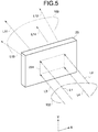
- FIG. 5 is a perspective view of the microlens array 23 as viewed from an incidence direction of the second light beam 102.
- a rectangle indicated by a dotted line in FIG. 5 represents a virtual contour of the intermediate image 231.
- the lateral direction of the intermediate image 231 is the main scanning direction
- the longitudinal direction orthogonal thereto is the sub-scanning direction.
- the intermediate image 231 is formed for each frame at a predetermined time (scanning time) in the main scanning direction and the sub-scanning direction.
- the intermediate image 231 formed at each moment (each frame rate) in the microlens array 23 is formed by "only the pixel irradiated with the second light beam 102 at that moment". Therefore, the "intermediate image 231 which is a two-dimensional color image” is a set of pixels displayed at each moment of two-dimensional scanning using the second light beam 102.
- the intermediate image 231 is emitted while being scattered by the microlens array 23, the intermediate image 231 can be visually recognized as the virtual image 2 even if positions of eyes of the driver 3 change due to an attitude of the driver 3 or the like.
- the HUD 1 includes an FPGA 600, a CPU 602, a ROM 604, a RAM 606, an I/F 608, a bus line 610, an LD driver 6111, and a MEMS controller 615.
- the FPGA 600 operates the light source unit 10 and the MEMS mirror 21 using the LD driver 6111 and the MEMS controller 615.
- the CPU 602 is a processor that controls an operation of each piece of the above-described hardware provided in the HUD 1.
- the ROM 604 is a semiconductor memory that stores an image processing program to be executed by the CPU 602 to control each function of the HUD 1.
- the RAM 606 is a semiconductor memory that is used as a work area when the CPU 602 executes control processing of each piece of hardware.
- the I/F 608 is a contact point that connects the HUD 1 to an external controller or the like.
- the HUD 1 is connected to a controller area network (CAN) or the like via the I/F 608.
- CAN controller area network
- the HUD 1 can operate while communicating with another external controller or the like connected via the CAN.
- the optical scanning unit 100 includes a vehicle information input unit 800, an external information input unit 802, an image information generating unit 804, and a display image forming unit 806.
- the vehicle information input unit 800 acquires information (for example, travel speed, travel distance, and the like of the vehicle) from another external controller or the like connected via the I/F 608.
- the external information input unit 802 acquires information (for example, position information based on a GPS, traffic information from a navigation device, and the like) from another external controller or the like connected via the I/F 608.
- the image information generating unit 804 generates information for forming the intermediate image 231 which serves as a source of the virtual image 2 (see FIG. 1 ) based on the information input from the vehicle information input unit 800 and the external information input unit 802.
- the display image forming unit 806 includes a control unit 8060.
- the control unit 8060 controls the operations of the light source unit 10 and the scanning optical system 20 based on the information generated by the image information generating unit 804. With this control function, the intermediate image 231 to be projected onto the windshield 50 is generated. With the operations of the functional blocks described above, it is possible to create a state where the virtual image 2 is visually recognized at the viewpoint of the driver 3.
- the HUD 1 is configured such that with the intermediate image formation unit (the microlens array 23) included in the optical scanning unit 100 as a boundary, the outside of the intermediate image formation unit connects with a space inside the vehicle.
- unnecessary light 5 such as sunlight which affects the display of the virtual image 2 enters the inside from the outside of the vehicle.
- the unnecessary light 5 is not limited to light arriving from above the vehicle, such as sunlight as exemplified in FIG. 1 , and arrives from various angles.
- the unnecessary light 5 passes through the observation optical system 30 and is incident on the microlens array 23, a state where the unnecessary light 5 is emitted from the microlens array 23 to the MEMS mirror 21 is reached. In this case, a situation where light different from the second light beam 102 forming the intermediate image 231 affects the intermediate image 231 is reached. As described above, the unnecessary light 5 causes a decrease in contrast of the intermediate image 231, and also causes a decrease in image quality of the intermediate image 231.
- the optical scanning unit 100 prevents the decrease in contrast of the intermediate image 231 caused by the influence of the unnecessary light 5.
- the optical scanning unit 100 according to the present embodiment prevents an erroneous operation of the synchronization signal sensor for forming the intermediate image 231, and forms the intermediate image 231 with good image quality.
- FIG. 15 is a schematic view for describing the influence of the unnecessary light 5, and is an example of a cross section in the sub-scanning direction of the optical scanning unit 100.
- a case where the transparent flat plate 22 is arranged to be parallel to the microlens array 23 is assumed.
- the unnecessary light 5 easily re-enters the microlens array 23.
- the re-entry herein means that the unnecessary light 5 becomes scattered light after passing through the microlens array 23 and entering the inside of the optical scanning unit 100, and is incident on the incidence surface of the microlens array 23.
- the unnecessary light 5 is scattered by the microlens array 23 in the case where the microlens array 23 and the transparent flat plate 22 are parallel, the scattered light is reflected by the transparent flat plate 22 or the MEMS mirror 21 and easily re-enters the microlens array 23. That is, when the microlens array 23 and the transparent flat plate 22 are parallel, there is a high possibility that the formation of the intermediate image 231 is adversely affected.
- the optical scanning unit 100 has an effect of preventing the above-described adverse effect by inclining the transparent flat plate 22 with respect to the microlens array 23 in a sub-scanning cross section as illustrated in FIGS. 8 and 9 .
- FIG. 8 illustrates an example of optical arrangement of the optical scanning unit 100 in a main scanning cross section.
- FIG. 9 illustrates an example of optical arrangement of the optical scanning unit 100 in the sub-scanning cross section.
- the microlens array 23 and the transparent flat plate 22 are parallel to each other in the main scanning cross section.
- a spreading angle at which the MEMS mirror 21 deflects the second light beam 102 in the main scanning direction is, for example, 52 degrees.
- the synchronization signal sensor that detects the second light beam 102 is arranged at an end of the microlens array 23 in the main scanning direction, and the synchronization signal sensor detects the second light beam 102 to adjust the position of the intermediate image 231, thereby improving the image quality.
- the optical scanning unit 100 is arranged such that the transparent flat plate 22 is inclined with respect to the microlens array 23 in the sub-scanning cross section so as to form an angle ⁇ .
- the transparent flat plate 22 is inclined with respect to the microlens array 23 in the sub-scanning cross section so as to form an angle ⁇ .
- An inclination direction of the transparent flat plate 22 in the optical scanning unit 100 is defined based on two virtual lines diagonally connecting ends of the transparent flat plate 22 and ends of the microlens array 23.
- One line of the above-described two virtual lines forms an angle with a perpendicular line of the transparent flat plate 22 smaller than the other line does.
- the transparent flat plate 22 is inclined in a direction in which the angle formed between this one line and the perpendicular line of the transparent flat plate 22 increases.
- the inclination of the transparent flat plate 22 with respect to the microlens array 23 will be described in more detail.
- one of ends of the microlens array 23 in the sub-scanning cross section will be referred to as an "end A”, and the other end will be referred to as an "end B".
- a virtual line connecting the end A and an end of the transparent flat plate 22 diagonal to the end A will be referred to as a "first virtual line 251”
- a virtual line connecting the end B and an end of the transparent flat plate 22 diagonal to the end B will be referred to as a "second virtual line 252".
- an angle formed between the first virtual line 251 and the perpendicular line 221 is smaller than an angle formed between the second virtual line 252 and the perpendicular line 221. That is, the transparent flat plate 22 of the optical scanning unit 100 is inclined in a direction C in which the angle formed between the first virtual line 251 and the perpendicular line 221 increases. In other words, the transparent flat plate 22 of the optical scanning unit 100 is inclined in a direction away from the state of being parallel to the microlens array 23.
- the unnecessary light 5 from the end A of the microlens array 23 is directed in a direction indicated by a reference sign A1 or a reference sign A2 if being reflected at the end of the transparent flat plate 22.
- the unnecessary light 5 from the end B of the microlens array 23 is directed in a direction indicated by a reference sign B1 or a reference sign B2 if being reflected at the end of the transparent flat plate 22.
- an angle formed when the unnecessary light 5, which has been scattered from the end A of the microlens array 23, is reflected by one end of the transparent flat plate 22 in the sub-scanning cross section is larger than an angle formed when the unnecessary light 5 is reflected by the other end. This also applies to the unnecessary light 5 scattered from the end B of the microlens array 23.
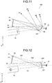
- an optical path closest to the microlens array 23 in the sub-scanning cross section is an optical path corresponding to the reference sign A1. In other words, there is no unnecessary light 5 that is reflected to be closer to the microlens array 23 than the reference sign A1, and the other unnecessary light 5 is reflected in a direction away from the microlens array 23.
- the transparent flat plate 22 If the transparent flat plate 22 is inclined in a direction opposite to the direction C illustrated in FIG. 10 , some of the unnecessary light 5 reflected by the transparent flat plate 22 returns to the microlens array 23.
- the unnecessary light 5 returns to the microlens array 23 a part of the microlens array 23 which does not contribute to the formation of the intermediate image 231 at the relevant moment (relevant frame) is brightened.
- the part that is originally dark becomes bright so that the contrast of the intermediate image 231 decreases.
- the optical scanning unit 100 can prevent the unnecessary light 5 from adversely affecting the intermediate image 231 since the scattered light from the whole region of the microlens array 23 does not re-enter the microlens array 23 even if being reflected by the transparent flat plate 22. As a result, it is possible to form the intermediate image 231 with the high contrast.
- one of the ends of the microlens array 23 in the sub-scanning cross section will be referred to as the "end A”, and the other end will be referred to as the "end B".
- the virtual line connecting the end A and the end of the transparent flat plate 22 diagonal to the end A will be referred to as the "first virtual line 251”
- the virtual line connecting the end B and the end of the transparent flat plate 22 diagonal to the end B will be referred to as the "second virtual line 252”.
- an inclination direction of the transparent flat plate 22 in the sub-scanning cross section is different from the embodiment described above. That is, the transparent flat plate 22 is inclined with respect to the microlens array 23 such that the angle formed between the second virtual line 252 and the perpendicular line 221 of the transparent flat plate 22 is smaller than the angle formed between the first virtual line 251 and the perpendicular line 221 of the transparent flat plate 22.
- the inclination direction of the transparent flat plate 22 is set to a direction in which the angle formed between the second virtual line 252 and the perpendicular line 221 increases, and in which the transparent flat plate 22 goes away from the state of being parallel to the microlens array 23.
- the second virtual line 252 becomes a line that contains an end of the transparent flat plate 22 further from the first light beam 101 incident on the MEMS mirror 21, that is, the end at a position diagonal to the end B of the microlens array 23.
- the inclination direction of the transparent flat plate 22 is set in this manner, it is possible to reduce incident angles of the light beams (the first light beam 101 and the second light beam 102) transmitted through the transparent flat plate 22, with respect to the transparent flat plate 22.
- the transparent flat plate 22 can be downsized, and the transmittance of the transparent flat plate 22 can be improved.
- the optical scanning unit 100 can prevent the entry of the unnecessary light 5 in a case where the light source unit 10 is turned off or to a part where the intermediate image 231 is not formed on the microlens array 23 since the scattered light from the entire region of the microlens array 23 does not re-enter the microlens array 23 even if being reflected by the transparent flat plate 22. As a result, it is possible to form the high-contrast intermediate image 231.
- the transparent flat plate 22 can be made compact and the transmittance can be improved by reducing the incident angles of the light beams (the first light beam 101 and the second light beam 102) transmitted through the transparent flat plate 22 with respect to the transparent flat plate 22 as described above.
- the incident angle of the first light beam 101 incident on the MEMS mirror 21 from the light source unit 10 in the sub-scanning cross section is set to 13 degrees, and an amplitude (MEMS amplitude) of the MEMS mirror 21 in the sub-scanning cross section is set to ⁇ 5 degrees.
- the incidence side is 13 degrees and the emission side is 23 degrees (13 degrees + 10 degrees) with respect to a sub-scanning amplitude center of the MEMS mirror 21.
- a center of the microlens array 23 coincides with a laser light arrival position at the center of the amplitude of the MEMS mirror 21 (MEMS amplitude center) and has a symmetric shape in the sub-scanning direction, the amounts of inclination of the transparent flat plate 22 inclined as described above are substantially the same. Therefore, it is possible to set the incident angle of the light beam to be transmitted through the transparent flat plate 22 to be smaller in the case in which the transparent flat plate 22 is inclined toward the incident light.
- the HUD 1 needs to make the intermediate image 231 brighter than the brightness of the background of the virtual image 2. That is, it is not desirable to lower the transmittance of light in the transparent flat plate 22 because a large amount of light is required due to the background of the virtual image 2.
- the incident angles of the transmitted light beams (the first light beam 101 and the second light beam 102) with respect to the transparent flat plate 22 are reduced according to the present embodiment, which leads to the improvement of the transmittance.
- the optical scanning unit 100 Since the optical scanning unit 100 according to the first or second embodiment described above is the laser scanning system, it is necessary to acquire a signal for controlling a light emission timing of the light source unit 10 in order to control a formation position of the intermediate image 231.
- This acquisition of the control signal is performed by a light receiving element 25 which is a synchronization signal sensor.
- the light receiving element is arranged in the sub-scanning cross section as illustrated in FIGS. 10 and 12 .
- the light receiving element 25 is desirably arranged at an end opposite to the end of the microlens array 23 contained in the line forming the smaller angle with the perpendicular line of the transparent flat plate 22 with respect to the center of the microlens array 23 in the sub-scanning cross section.
- the light receiving element 25 is arranged at the end B of the microlens array 23.
- the light receiving element 25 is arranged at the end A of the microlens array 23.
- the light receiving element 25 When the light receiving element 25 is arranged outside the microlens array 23, particularly on a side where the unnecessary light 5 is released, it is unnecessary to set the amount by which the perpendicular line of the transparent flat plate 22 is inclined in the direction in which the angle formed by the transparent flat plate 22 and the microlens array 23 increases, to be large.
- the transparent flat plate 22 can be downsized, and the transmittance can be improved.
- the transparent flat plate 22 is arranged to have an angle in the sub-scanning direction so as to prevent the incident light (first light beam 101) incident on the MEMS mirror 21 from being perpendicularly incident on the transparent flat plate 22. If the first light beam 101 is incident perpendicularly on the transparent flat plate 22, there is a possibility that the reflected light of the first light beam 101 returns to the light source unit 10.
- the light amount control becomes unstable as the light amount of the first light beam 101 fluctuates. Even in the light source unit 10 which does not monitor the amount of light, there is a case where an optical system that separates the incident light on the MEMS mirror 21 to monitor the amount of light, or the like is provided. In either case, it is not desirable that the first light beam 101 returns to the light source unit 10 by the transparent flat plate 22.
- the transparent flat plate 22 is arranged to have the angle in the sub-scanning direction with respect to the incident light with respect to the MEMS mirror 21 as in the optical scanning unit 100 according to any of the above embodiments, it is possible to prevent the light from being reflected to the sensor that controls the amount of light or the like and to accurately control the light amount of the first light beam 101.
- the HUD 1 can accurately perform reproduction of the color of color display and setting of the appropriate brightness with respect to the brightness of the background during the display of the virtual image 2.
- the first light beam 101 from the light source unit 10 is used for two-dimensional scanning by the MEMS mirror 21 having the single reflection surface 2101 and is imaged to form the intermediate image 231 on the microlens array 23 which is a surface to be scanned.
- the transparent flat plate 22 to be arranged for the purpose of improving the operation accuracy of the MEMS mirror 21 and improving the image quality is arranged so as to satisfy a predetermined condition in the sub-scanning cross section.
- the predetermined condition means the inclination direction of the transparent flat plate 22 with respect to the line, which forms the smaller angle with the perpendicular line of the transparent flat plate 22, of the two lines each of which diagonally connects an end of the transparent flat plate 22 and an end of the microlens array 23.
- the inclination direction is the direction in which the angle formed by the transparent flat plate 22 and the microlens array 23 increases, with respect to the perpendicular line of the transparent flat plate 22.
- the HUD 1 can form the high-contrast intermediate image 231 and display the high-contrast virtual image 2.
- the synchronization signal for controlling the formation position of the intermediate image 231 can be constantly acquired in a stable manner, and the image quality of the intermediate image 231 can be improved.
- the line forming the smaller angle with the perpendicular line of the transparent flat plate 22 may be the line containing the end of the transparent flat plate 22 further from the light beam (first light beam 101) incident on the MEMS mirror 21. According to this, it is possible to downsize the transparent flat plate 22 and to secure the transmittance.
- At least the single light receiving element 25 configured to obtain the signal for determining the scanning timing is arranged at the end opposite to the end of the microlens array 23 contained in the line forming the smaller angle with the perpendicular line of the transparent flat plate 22, with respect to the center of the microlens array 23 in the sub-scanning cross section.
- Patent Literature 1 Japanese Patent No. 5050862
Landscapes
- Engineering & Computer Science (AREA)
- Physics & Mathematics (AREA)
- Chemical & Material Sciences (AREA)
- Combustion & Propulsion (AREA)
- Transportation (AREA)
- Mechanical Engineering (AREA)
- General Physics & Mathematics (AREA)
- Optics & Photonics (AREA)
- Mechanical Optical Scanning Systems (AREA)
- Mechanical Light Control Or Optical Switches (AREA)
- Instrument Panels (AREA)
Abstract
Description
- The present invention relates to an optical scanning device, an image display device, and a vehicle. Background
- There has been known an image display device that enables an operator (driver) to visually recognize useful information with small line-of-sight movement when the operator steers a moving object, the device mounted on the moving object such as a vehicle, an aircraft, and a ship. Such an image display device is generally called a head-up display (hereinafter referred to as the "HUD").
- The HUD forms an intermediate image based on information on the moving object, and displays the intermediate image as a virtual image in the driver's field of view. Several kinds of systems that form the intermediate image in the HUD have been known. Examples thereof include a panel system using an imaging device such as liquid crystal, a laser scanning system that two-dimensionally scans a laser beam emitted from a laser diode (hereinafter referred to as the LD), and the like. In the panel system, light emission of the entire screen is partially shielded to form an intermediate image. In the laser scanning system, "light emission" or "non-light emission" is allocated to each pixel to form an intermediate image (for example, see Patent Literature 1).
- The laser scanning system can form the intermediate image with higher contrast than the panel system. It is desirable that unnecessary light other than a laser beam to form the intermediate image (hereinafter referred to as "unnecessary light") do not reach a portion forming the intermediate image in order to increase the contrast of the intermediate image and enhance the visibility of the virtual image.
- In addition, it is necessary to control a light emission timing of the LD in order to form the intermediate image at a desired position in the laser scanning system. For this purpose, a light receiving element that detects scanning light consisting of a laser beam from the LD is used. When the unnecessary light as described above is incident on the light receiving element, a formation position of the intermediate image is disturbed, which causes a decrease in image quality of the intermediate image.
- In addition, the visibility of the virtual image to be displayed in the HUD may decrease depending on brightness of the background in some cases. Therefore, it is desirable to be capable of adjusting brightness of the intermediate image in relation to the brightness of the background of the virtual image.
- An object of the present invention is to provide an optical scanning device capable of forming a high-contrast intermediate image even when unnecessary light intrudes and capable of stably displaying a virtual image with good image quality.
- An optical scanning device according to the present invention includes: a light source unit configured to emit a light beam; a light deflecting unit configured to two-dimensionally deflect the light beam in a main scanning direction and a sub-scanning direction orthogonal to the main scanning direction; and an image formation unit configured to form an image by two-dimensional scanning of the light beam performed by the light deflecting unit, wherein a flat plate configured to transmit light incident on the light deflecting unit and deflected reflection light from the light deflecting unit, is arranged in an optical path of the light beam between the light deflecting unit and the image formation unit, and the flat plate is inclined with respect to the image formation unit in a cross section in the sub-scanning direction.
- According to the present invention, it is possible to form the high-contrast intermediate image even when the unnecessary light intrudes and to stably display the virtual image with good image quality.
-
-
FIG. 1 is a configuration view illustrating an example of an embodiment of an image display device according to the present invention. -
FIG. 2 is a configuration view illustrating an example of a light source unit according to the image display device. -
FIG. 3 is a configuration view illustrating an example of a scanning optical system according to the image display device. -
FIG. 4 is a plan view illustrating an example of an optical scanning means according to the image display device. -
FIG. 5 is a perspective view illustrating an example of an intermediate image formation unit according to the image display device. -
FIG. 6 is a block diagram illustrating an example of a hardware configuration of the image display device. -
FIG. 7 is a functional block diagram illustrating an example of a functional configuration of the image display device. -
FIG. 8 is an optical arrangement view of an embodiment of an optical scanning device according to the present invention in a cross section in a main scanning direction. -
FIG. 9 is an optical arrangement view of the embodiment of the optical scanning device according to the present invention in a cross section in a sub-scanning direction. -
FIG. 10 is a view for describing the embodiment of the optical scanning device according to the present invention. -
FIG. 11 is a view for describing an effect of the embodiment of the optical scanning device according to the present invention. -
FIG. 12 is an optical arrangement view of another embodiment of the optical scanning device according to the present invention in a cross section in the sub-scanning direction. -
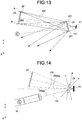
FIG. 13 is a view for describing an effect of another embodiment of the optical scanning device according to the present invention. -
FIG. 14 is an optical arrangement view of still another embodiment of the optical scanning device according to the present invention in a cross section in the sub-scanning direction. -
FIG. 15 is a view for describing unnecessary light related to the present invention. - Hereinafter, embodiments of an optical scanning device, an image display device, and a vehicle according to the present invention will be described with reference to the drawings. First, an embodiment of an image display device including an optical scanning device will be described.
- As illustrated in
FIG. 1 , anHUD 1, which is an embodiment of the image display device according to the present invention, is a device mounted on and used in a vehicle. TheHUD 1 displays information useful for adriver 3 as avirtual image 2 in the field of view of thedriver 3 of the vehicle. Here, the "information useful for thedriver 3" is information including information on an object or the like existing in the field of view of thedriver 3, information on an operation of the vehicle, and the like. In addition, the "information useful for thedriver 3" also includes information on warning or the like to provide notification of an abnormality in the operation of the vehicle. Hereinafter, the above-described "information useful for thedriver 3" may be referred to as the "information" in some cases in the description of the present specification. - A form of the
HUD 1 illustrated inFIG. 1 is a form in which awindshield 50, which is a front windshield of the vehicle, is used as anoptical combiner 32. Theoptical combiner 32 is a transmission reflection member onto which anintermediate image 231 to be described later is projected and which reflects the projectedintermediate image 231 toward thedriver 3 and transmits light (external light) from environment or an object existing in the field of view of thedriver 3. Incidentally, a transmission reflection type optical element that is separated from thewindshield 50 may be used as theoptical combiner 32. - The
HUD 1 includes alight source unit 10, a scanningoptical system 20, and an observationoptical system 30. Thelight source unit 10 and the scanningoptical system 20 constitute anoptical scanning unit 100 which is the optical scanning device according to the present invention. - The
intermediate image 231 is formed in theoptical scanning unit 100. Theintermediate image 231 appears on a side close to aconcave mirror 31 forming a part of the observationoptical system 30, in theoptical scanning unit 100. Theconcave mirror 31 reflects theintermediate image 231 to be projected onto theoptical combiner 32. Theoptical combiner 32 displays theintermediate image 231 so that thedriver 3 can visually recognize thevirtual image 2. - The
light source unit 10 emits a light beam for forming theintermediate image 231. When thevirtual image 2 is set to be a color image, light beams corresponding to three primary colors of light required for the color image is emitted from thelight source unit 10. - The scanning
optical system 20 forms theintermediate image 231 based on the light beam emitted from thelight source unit 10. The scanningoptical system 20 emits the formedintermediate image 231 toward the observationoptical system 30. Incidentally, a general outer shape of theintermediate image 231 is a rectangle or the like. - The observation
optical system 30 includes theconcave mirror 31, which is a reflective optical element, and theoptical combiner 32. Theintermediate image 231 formed in the scanningoptical system 20 is magnified in theconcave mirror 31 and projected onto theoptical combiner 32. The magnified and projectedintermediate image 231 is reflected by theoptical combiner 32 toward thedriver 3. - The
intermediate image 231 reflected by theoptical combiner 32 is visually recognized as thevirtual image 2 at a position different from a physical position of the optical combiner 32 (a position in a direction away from the driver 3) in the vision of thedriver 3. As described above, the information displayed by thevirtual image 2 is information on the front of the vehicle, information on the operation of the vehicle, navigation information such as speed and travel distance of the vehicle, a destination display, and the like. - Incidentally, a viewpoint position serving as a reference (a reference eye point) is simply illustrated as a viewpoint of the
driver 3. A viewpoint range of thedriver 3 is equal to or smaller than a driver's eye range for a vehicle (JIS D0021). - Here, the "direction" according to the description of the present embodiment will be defined. The
intermediate image 231 is an image generated by two-dimensional scanning executed by the scanningoptical system 20. Here, the two-dimensional scanning is scanning obtained by combining scanning in two directions of a main scanning direction and a sub-scanning direction. In addition, the main scanning direction and the sub-scanning direction correspond to a left-right direction and an up-down direction of theintermediate image 231. - The left-right direction of the
intermediate image 231 corresponds to a direction which is the same as a direction that is viewed as a left-right direction when thedriver 3 visually recognizes thevirtual image 2. Similarly, the up-down direction of theintermediate image 231 corresponds to a direction which is the same as a direction that is viewed as an up-down direction when thedriver 3 visually recognizes thevirtual image 2. The left-right direction of theintermediate image 231 is the main scanning direction, and the up-down direction thereof is the sub-scanning direction. - In the following description, the main scanning direction at the time of generating the
intermediate image 231 will be defined as an "X direction" and the sub-scanning direction thereof will be defined as a "Y direction". When describing the lateral direction in thevirtual image 2, the lateral direction will be referred to as the "X direction" as the direction corresponding to the main scanning direction in theintermediate image 231 even if there is a difference in physical directions. In addition, when describing the Y direction in thevirtual image 2, the Y direction will be referred to as the "Y direction" as the direction corresponding to the sub-scanning direction in theintermediate image 231 even if there is a difference in physical directions. - In addition, when the
HUD 1 is mounted on the vehicle as illustrated inFIG. 1 , a traveling direction of the vehicle will be defined as a "Z' direction", a left-right direction of the vehicle will be defined as an "X' direction" and an up-down direction of the vehicle will be defined as a "Y' direction". In this case, a direction toward thedriver 3 from the virtual image 2 (a backward direction of the vehicle) will be defined as the +Z' direction and a line-of-sight direction of the driver 3 (a forward direction of the vehicle) is defined as a -Z' direction. In addition, a rightward direction (a back direction of the sheet) of thedriver 3 is defined as a + X' direction, and a leftward direction of thedriver 3 is defined as a -X' direction (a front direction of the sheet). In addition, an upward direction of thedriver 3 is defined as a + Y' direction, and a downward direction of thedriver 3 is defined as a -Y' direction. - In
FIG. 1 , the X direction of thevirtual image 2 and the X' direction (left-right direction) of the vehicle coincide. In addition, the Y direction of thevirtual image 2 and the Y' direction (up-down direction) of the vehicle coincide. On the other hand, there is a case where the X direction (main scanning direction) and the X' direction (left-right direction) of theintermediate image 231 generated in the scanningoptical system 20 do not coincide. Similarly, there is a case where the Y direction (sub-scanning direction) and the Y' direction (up-down direction) of theintermediate image 231 do not coincide. This is because the physical directions of theintermediate image 231 in the main scanning direction and the sub-scanning direction are not necessarily orthogonal to an X'-axis, a Y'-axis, and a Z'-axis depending on arrangement and directions of optical elements in the scanningoptical system 20 and optical arrangement of the scanningoptical system 20 and the observationoptical system 30. - As illustrated in
FIG. 1 , a center of an incidence region of the image light projected from theconcave mirror 31 to theoptical combiner 32 is set as anincidence region center 303. As illustrated inFIG. 1 , a tangential plane at theincidence region center 303 is inclined with respect to a firstvirtual axis 304 connecting the viewpoint of thedriver 3 and a center of the virtual image 2 (a virtual image center 305) when viewed from the X'-axis direction. Incidentally, the firstvirtual axis 304 is an axis that passes through theincidence region center 303. When assuming a secondvirtual axis 306 that connects a center of theintermediate image 231 formed in the scanningoptical system 20 and areflection surface center 307, the secondvirtual axis 306 is inclined with respect to the firstvirtual axis 304 when viewed from the X'-axis direction as illustrated inFIG. 1 . In addition, the secondvirtual axis 306 is inclined with respect to the firstvirtual axis 304 when viewed from the Y'-axis direction. - Next, a detailed configuration of the
light source unit 10 will be described with reference toFIG. 2 . Thelight source unit 10 combines the light beams corresponding to the three primary colors of light into one light beam and emit the combined light beam so that thevirtual image 2 is the color image. In the following description, the light beam emitted from thelight source unit 10 and directed to a light scanning means to be described later will be referred to as afirst light beam 101. - The
light source unit 10 includes, for example, three semiconductor laser elements. Each of the semiconductor laser elements is a light source element corresponding to one of the three primary colors of light. Afirst laser element 110 is a laser element that emits laser light of red (R). Asecond laser element 120 is a laser element that emits laser light of green (G). Athird laser element 130 is a laser element that emits laser light of blue (B). - Incidentally, a laser diode (LD) called an edge-emitting laser or a vertical-cavity surface-emitting laser (VCSEL) can be also used for each laser element. In addition, an LED element can also be used instead of the semiconductor laser element.
- In addition to the respective laser elements, the
light source unit 10 includes coupling lenses each of which suppresses divergence of the laser light emitted from one of laser elements. In addition, thelight source unit 10 includes apertures each of which regulates a light beam diameter of laser light from one of coupling lenses, for shaping. In addition, thelight source unit 10 includes abeam combining prism 140 that combines the laser light beams of the respective colors shaped by the respective apertures and emit the combined light beam, and alens 150. - The coupling lenses corresponding to the laser elements of respective colors will be referred to as a
first coupling lens 111, asecond coupling lens 121, and athird coupling lens 131. - The apertures corresponding to the respective laser elements will be referred to as a
first aperture 112, asecond aperture 122, and athird aperture 132. - The
beam combining prism 140 includes a firstdichroic film 141 that transmits red laser light and reflects green laser light and a seconddichroic film 142 that transmits red and green laser light and reflects blue laser light. - The
lens 150 converts the light beam emitted from thebeam combining prism 140 into a "beam in a desired condensed state". - A wavelength λR of the light beam (laser light) emitted from the
first laser element 110 is, for example, 640 nm. A wavelength λG of the light beam (laser light) emitted from thesecond laser element 120 is, for example, 530 nm. A wavelength λB of the light beam (laser light) emitted from thethird laser element 130 is, for example, 445 nm. - The red laser light emitted from the
first laser element 110 is incident on thebeam combining prism 140 via thefirst coupling lens 111 and thefirst aperture 112. The red laser light incident on thebeam combining prism 140 passes through the firstdichroic film 141 and travels straight. - The green laser light emitted from the
second laser element 120 is incident on thebeam combining prism 140 via thesecond coupling lens 121 and thesecond aperture 122. The green laser light incident on thebeam combining prism 140 is reflected by the firstdichroic film 141 to be directed in the same direction as the red laser light (in the direction toward the second dichroic film 142) . - The blue laser light emitted from the
third laser element 130 is incident on thebeam combining prism 140 via thethird coupling lens 131 and thethird aperture 132. The blue laser light incident on thebeam combining prism 140 is reflected by the seconddichroic film 142 to be directed in the same direction as the red laser light and the green laser light. - In the manner described above, the light beam obtained by combining the red laser light, the green laser light, and the blue laser light is emitted from the
beam combining prism 140. - The light beam emitted from the
beam combining prism 140 is converted by thelens 150 into thefirst light beam 101 which is the "beam in a desired condensed state". Thefirst light beam 101 is a light beam into which the red laser light, the green laser light, and the blue laser light are combined as one laser light beam. - The laser light beam of each color of R (red), G (green), and B (blue) included in the
first light beam 101 is intensity-modulated in accordance with an image signal relating to a "two-dimensional color image" to be displayed. Alternatively, the intensity modulation is performed in accordance with image data indicating the relevant image information relating to the "two-dimensional color image" to be displayed. The intensity modulation of the laser light beams may be performed using a system that directly modulates a semiconductor laser of each color (a direct modulation system) or a system that modulates a laser light beam emitted from a semiconductor laser of each color (an external modulation system). - Incidentally, apertures having various shapes such as a circle, an ellipse, a rectangle, and a square, may be used as each aperture in accordance with a divergence angle of a light beam or the like. In addition, the
lens 150 is a meniscus lens that has a concave surface toward aMEMS mirror 21 to be described later. - As illustrated in
FIG. 3 , the scanningoptical system 20 includes theMEMS mirror 21 that deflects thefirst light beam 101, a transparentflat plate 22, and amicrolens array 23 which is an intermediate image formation unit. - The scanning
optical system 20 is an optical system that deflects thefirst light beam 101 emitted from thelight source unit 10 by theMEMS mirror 21. The light beam deflected in the scanningoptical system 20 is incident on themicrolens array 23 as a secondlight beam 102. - As illustrated in
FIG. 3 , thefirst light beam 101 from thelight source unit 10 passes through the transparentflat plate 22 in the middle of entering theMEMS mirror 21. In addition, the secondlight beam 102 deflected by theMEMS mirror 21 passes through the transparentflat plate 22 in the middle of entering themicrolens array 23. That is, both the light beam incident on theMEMS mirror 21 and the light beam emitted from theMEMS mirror 21 pass through the transparentflat plate 22. - More specifically, the
MEMS mirror 21 is arranged in a sealed region, and entry of the laser light into the region and emission of the laser light from the region are performed through the transparentflat plate 22. Incidentally, the transparentflat plate 22, theMEMS mirror 21, and the like are configured as an integrated module. - The
microlens array 23 is scanned in two dimensions including the main scanning direction and the sub-scanning direction with the secondlight beam 102 deflected by theMEMS mirror 21. Theintermediate image 231 is generated by the two-dimensional scanning with respect to themicrolens array 23. Theimage light 103 according to the generatedintermediate image 231 is emitted from an emission surface of themicrolens array 23 and is directed to the observationoptical system 30. - Here, the
MEMS mirror 21 will be described in detail with reference toFIG. 4 . TheMEMS mirror 21 corresponds to micro electro mechanical systems (MEMS) manufactured as a micro-oscillating mirror element by a semiconductor process or the like, and includes amicromirror 210 in a central portion thereof. Themicromirror 210 is a light deflecting unit that deflects thefirst light beam 101 emitted from thelight source unit 10 and two-dimensionally scans themicrolens array 23. - The
micromirror 210 has areflection surface 2101 that reflects thefirst light beam 101. Thereflection surface 2101 is configured to rotate about two axes. When thereflection surface 2101 is rotated about the axis in the Y direction, a traveling direction of the secondlight beam 102 changes with respect to the X direction. Therefore, when thereflection surface 2101 is rotated about the axis in the Y direction, it is possible to execute main scanning for generating theintermediate image 231. In addition, when thereflection surface 2101 is rotated about the axis in the X direction, the traveling direction of the secondlight beam 102 changes with respect to the Y direction. Therefore, when thereflection surface 2101 is rotated about the axis in the X direction, it is possible to execute sub-scanning for generating theintermediate image 231. That is, the X direction corresponds to the main scanning direction, and the Y direction corresponds to the sub-scanning direction inFIG. 4 . - A pair of
meandering crossbeam portions 152 formed to meander through a plurality of folded portions is arranged on both sides of themicromirror 210 in the X direction. Crossbeams folded and adjacent to each other in the meanderingcrossbeam portions 152 are divided into afirst crossbeam portion 152a and asecond crossbeam portion 152b, and each crossbeam portion includes apiezoelectric member 156. Thepiezoelectric member 156 used here is, for example, PZT. - Voltages to be applied to the
first crossbeam portion 152a and thesecond crossbeam portion 152b are independently applied to adjacent crossbeams. These independently applied voltages have different voltage values from each other. Different warps occur in thefirst crossbeam portion 152a and thesecond crossbeam portion 152b, to which the different voltages are applied. A direction of the warp is determined depending on the applied voltage. That is, thefirst crossbeam portions 152a and thesecond crossbeam portions 152b adjacent to each other are deflected in directions different from each other. Incidentally, the meanderingcrossbeam portion 152 is supported by aframe member 154. - As the above-described deflection is accumulated, the
micromirror 210 rotates so as to change the direction of thereflection surface 2101 with respect to the X direction about the axis in the X direction. Thefirst light beam 101 is reflected by the rotation of thereflection surface 2101 about the axis in the X direction and scans themicrolens array 23 in the Y direction as the secondlight beam 102. - The
MEMS mirror 21 performs sine wave oscillation in the main scanning direction and sawtooth oscillation in the sub-scanning direction to two-dimensionally deflect thefirst light beam 101 into the second light beam, thereby two-dimensionally scanning themicrolens array 23. - When the
MEMS mirror 21 having the above configuration is used, theHUD 1 can perform optical scanning in the vertical direction (Y direction) using the axis in the X direction as the rotation center with a low voltage. On the other hand, optical scanning in the horizontal direction (X direction) using the axis in the Y direction as the rotation center is performed through resonance using a torsion bar or the like connected to themicromirror 210. - Next, the
microlens array 23 will be described in detail. In themicrolens array 23, a lens surface on which fine convex lenses are two-dimensionally arranged is an incidence surface, and a flat surface opposite to the lens surface is an emission surface. Incidentally, an optical element used as themicrolens array 23 is not limited to the above-described example, and a diffusion plate, a transmission screen, a reflection screen, or the like may be adopted. - The second
light beam 102 incident on the lens surface is diffused and emitted from the emission surface. The scanning performed by theMEMS mirror 21 is, for example, a raster scan in which the main scanning direction is scanned at high speed and the sub-scanning direction is scanned at low speed. - As described above, the
first light beam 101 emitted from thelight source unit 10 of theHUD 1 supports color. Therefore, theintermediate image 231 formed in themicrolens array 23 is the color image. Incidentally, the monochromeintermediate image 231 may be formed in themicrolens array 23. -
FIG. 5 is a perspective view of themicrolens array 23 as viewed from an incidence direction of the secondlight beam 102. A rectangle indicated by a dotted line inFIG. 5 represents a virtual contour of theintermediate image 231. With thefirst light beam 101 which has been two-dimensionally deflected by theMEMS mirror 21, as the secondlight beam 102, scan is performed along the main scanning direction from L1 to L2 illustrated inFIG. 5 as the secondlight beam 102. Next, scan is performed along the main scanning direction after moving downward by one step in the sub-scanning direction from L1. Finally, theintermediate image 231 of one frame is formed by main scanning from L3 to L4. As described above, the lateral direction of theintermediate image 231 is the main scanning direction, and the longitudinal direction orthogonal thereto is the sub-scanning direction. Theintermediate image 231 is formed for each frame at a predetermined time (scanning time) in the main scanning direction and the sub-scanning direction. When the scanning of one frame is completed, the main scanning starts from L1 in order to form theintermediate image 231 of the next frame within the scanning time. - The
intermediate image 231 formed at each moment (each frame rate) in themicrolens array 23 is formed by "only the pixel irradiated with the secondlight beam 102 at that moment". Therefore, the "intermediate image 231 which is a two-dimensional color image" is a set of pixels displayed at each moment of two-dimensional scanning using the secondlight beam 102. - Since the
intermediate image 231 is emitted while being scattered by themicrolens array 23, theintermediate image 231 can be visually recognized as thevirtual image 2 even if positions of eyes of thedriver 3 change due to an attitude of thedriver 3 or the like. - Here, a configuration of a control system that controls an operation of the
optical scanning unit 100 of theHUD 1 will be described. As illustrated inFIG. 6 , theHUD 1 includes anFPGA 600, aCPU 602, aROM 604, aRAM 606, an I/F 608, abus line 610, anLD driver 6111, and aMEMS controller 615. - The
FPGA 600 operates thelight source unit 10 and theMEMS mirror 21 using theLD driver 6111 and theMEMS controller 615. TheCPU 602 is a processor that controls an operation of each piece of the above-described hardware provided in theHUD 1. TheROM 604 is a semiconductor memory that stores an image processing program to be executed by theCPU 602 to control each function of theHUD 1. TheRAM 606 is a semiconductor memory that is used as a work area when theCPU 602 executes control processing of each piece of hardware. - The I/
F 608 is a contact point that connects theHUD 1 to an external controller or the like. For example, theHUD 1 is connected to a controller area network (CAN) or the like via the I/F 608. As a result, theHUD 1 can operate while communicating with another external controller or the like connected via the CAN. - Next, a functional configuration of the
optical scanning unit 100 included in theHUD 1 will be described. As illustrated inFIG. 7 , theoptical scanning unit 100 includes a vehicleinformation input unit 800, an externalinformation input unit 802, an imageinformation generating unit 804, and a displayimage forming unit 806. - The vehicle
information input unit 800 acquires information (for example, travel speed, travel distance, and the like of the vehicle) from another external controller or the like connected via the I/F 608. - The external
information input unit 802 acquires information (for example, position information based on a GPS, traffic information from a navigation device, and the like) from another external controller or the like connected via the I/F 608. - The image
information generating unit 804 generates information for forming theintermediate image 231 which serves as a source of the virtual image 2 (seeFIG. 1 ) based on the information input from the vehicleinformation input unit 800 and the externalinformation input unit 802. - The display
image forming unit 806 includes acontrol unit 8060. Thecontrol unit 8060 controls the operations of thelight source unit 10 and the scanningoptical system 20 based on the information generated by the imageinformation generating unit 804. With this control function, theintermediate image 231 to be projected onto thewindshield 50 is generated. With the operations of the functional blocks described above, it is possible to create a state where thevirtual image 2 is visually recognized at the viewpoint of thedriver 3. - The description will be given returning to
FIG. 1 . TheHUD 1 is configured such that with the intermediate image formation unit (the microlens array 23) included in theoptical scanning unit 100 as a boundary, the outside of the intermediate image formation unit connects with a space inside the vehicle. There is a case whereunnecessary light 5 such as sunlight which affects the display of thevirtual image 2, enters the inside from the outside of the vehicle. Theunnecessary light 5 is not limited to light arriving from above the vehicle, such as sunlight as exemplified inFIG. 1 , and arrives from various angles. - In addition, when the
unnecessary light 5 passes through the observationoptical system 30 and is incident on themicrolens array 23, a state where theunnecessary light 5 is emitted from themicrolens array 23 to theMEMS mirror 21 is reached. In this case, a situation where light different from the secondlight beam 102 forming theintermediate image 231 affects theintermediate image 231 is reached. As described above, theunnecessary light 5 causes a decrease in contrast of theintermediate image 231, and also causes a decrease in image quality of theintermediate image 231. - In addition, similarly, a case where the
unnecessary light 5 is incident on a synchronization signal sensor that detects the secondlight beam 102 to control a position where theintermediate image 231 is formed in themicrolens array 23, is also conceivable. In this case, the amount of light detected by the synchronization signal sensor becomes unstable, and a synchronization signal is detected at a timing different from a timing at which detection needs to be performed, which causes a remarkably decrease in image quality of theintermediate image 231. - Next, an embodiment of the
optical scanning unit 100 will be described in more detail. Theoptical scanning unit 100 according to the present embodiment prevents the decrease in contrast of theintermediate image 231 caused by the influence of theunnecessary light 5. In addition, theoptical scanning unit 100 according to the present embodiment prevents an erroneous operation of the synchronization signal sensor for forming theintermediate image 231, and forms theintermediate image 231 with good image quality. -
FIG. 15 is a schematic view for describing the influence of theunnecessary light 5, and is an example of a cross section in the sub-scanning direction of theoptical scanning unit 100. As illustrated inFIG. 15 , a case where the transparentflat plate 22 is arranged to be parallel to themicrolens array 23 is assumed. In the arrangement relationship as illustrated inFIG. 15 , theunnecessary light 5 easily re-enters themicrolens array 23. The re-entry herein means that theunnecessary light 5 becomes scattered light after passing through themicrolens array 23 and entering the inside of theoptical scanning unit 100, and is incident on the incidence surface of themicrolens array 23. - When the
unnecessary light 5 is scattered by themicrolens array 23 in the case where themicrolens array 23 and the transparentflat plate 22 are parallel, the scattered light is reflected by the transparentflat plate 22 or theMEMS mirror 21 and easily re-enters themicrolens array 23. That is, when themicrolens array 23 and the transparentflat plate 22 are parallel, there is a high possibility that the formation of theintermediate image 231 is adversely affected. - The
optical scanning unit 100 according to the present embodiment has an effect of preventing the above-described adverse effect by inclining the transparentflat plate 22 with respect to themicrolens array 23 in a sub-scanning cross section as illustrated inFIGS. 8 and9 . -
FIG. 8 illustrates an example of optical arrangement of theoptical scanning unit 100 in a main scanning cross section.FIG. 9 illustrates an example of optical arrangement of theoptical scanning unit 100 in the sub-scanning cross section. As illustrated inFIG. 8 , themicrolens array 23 and the transparentflat plate 22 are parallel to each other in the main scanning cross section. A spreading angle at which theMEMS mirror 21 deflects the secondlight beam 102 in the main scanning direction is, for example, 52 degrees. In this case, the synchronization signal sensor that detects the secondlight beam 102 is arranged at an end of themicrolens array 23 in the main scanning direction, and the synchronization signal sensor detects the secondlight beam 102 to adjust the position of theintermediate image 231, thereby improving the image quality. - As illustrated in
FIG. 9 , theoptical scanning unit 100 according to the present embodiment is arranged such that the transparentflat plate 22 is inclined with respect to themicrolens array 23 in the sub-scanning cross section so as to form an angle α. As a result, even if theunnecessary light 5 incident from themicrolens array 23 exists, it is difficult for theunnecessary light 5 to be reflected by the transparentflat plate 22 and re-enter themicrolens array 23. - An inclination direction of the transparent
flat plate 22 in theoptical scanning unit 100 according to the present embodiment is defined based on two virtual lines diagonally connecting ends of the transparentflat plate 22 and ends of themicrolens array 23. One line of the above-described two virtual lines forms an angle with a perpendicular line of the transparentflat plate 22 smaller than the other line does. The transparentflat plate 22 is inclined in a direction in which the angle formed between this one line and the perpendicular line of the transparentflat plate 22 increases. - The inclination of the transparent
flat plate 22 with respect to themicrolens array 23 according to the present embodiment will be described in more detail. As illustrated inFIG. 10 , one of ends of themicrolens array 23 in the sub-scanning cross section will be referred to as an "end A", and the other end will be referred to as an "end B". In addition, in the sub-scanning cross section, a virtual line connecting the end A and an end of the transparentflat plate 22 diagonal to the end A will be referred to as a "firstvirtual line 251", and a virtual line connecting the end B and an end of the transparentflat plate 22 diagonal to the end B will be referred to as a "secondvirtual line 252". - When virtual
perpendicular lines 221 are set at both the ends of the transparentflat plate 22 in the sub-scanning section, an angle formed between the firstvirtual line 251 and theperpendicular line 221 is smaller than an angle formed between the secondvirtual line 252 and theperpendicular line 221. That is, the transparentflat plate 22 of theoptical scanning unit 100 is inclined in a direction C in which the angle formed between the firstvirtual line 251 and theperpendicular line 221 increases. In other words, the transparentflat plate 22 of theoptical scanning unit 100 is inclined in a direction away from the state of being parallel to themicrolens array 23. - An effect of the case where the transparent
flat plate 22 is inclined as described above will be described with reference toFIG. 11 . Assuming optical paths of theunnecessary light 5 as illustrated inFIG. 11 , theunnecessary light 5 from the end A of themicrolens array 23 is directed in a direction indicated by a reference sign A1 or a reference sign A2 if being reflected at the end of the transparentflat plate 22. Similarly, theunnecessary light 5 from the end B of themicrolens array 23 is directed in a direction indicated by a reference sign B1 or a reference sign B2 if being reflected at the end of the transparentflat plate 22. - When the transparent
flat plate 22 is arranged to be inclined with respect to themicrolens array 23 as illustrated inFIG. 10 , a state where theunnecessary light 5 scattered from themicrolens array 23 does not re-enter themicrolens array 23 even if being reflected by the transparentflat plate 22 is reached. - When the transparent
flat plate 22 is inclined in the direction C (seeFIG. 10 ), an angle formed when theunnecessary light 5, which has been scattered from the end A of themicrolens array 23, is reflected by one end of the transparentflat plate 22 in the sub-scanning cross section is larger than an angle formed when theunnecessary light 5 is reflected by the other end. This also applies to theunnecessary light 5 scattered from the end B of themicrolens array 23. When the scatteredunnecessary light 5 is reflected by the transparentflat plate 22, an optical path closest to themicrolens array 23 in the sub-scanning cross section is an optical path corresponding to the reference sign A1. In other words, there is nounnecessary light 5 that is reflected to be closer to themicrolens array 23 than the reference sign A1, and the otherunnecessary light 5 is reflected in a direction away from themicrolens array 23. - If the transparent
flat plate 22 is inclined in a direction opposite to the direction C illustrated inFIG. 10 , some of theunnecessary light 5 reflected by the transparentflat plate 22 returns to themicrolens array 23. When theunnecessary light 5 returns to themicrolens array 23, a part of themicrolens array 23 which does not contribute to the formation of theintermediate image 231 at the relevant moment (relevant frame) is brightened.
When such a state occurs, the part that is originally dark becomes bright so that the contrast of theintermediate image 231 decreases. - The
optical scanning unit 100 according to the first embodiment described above can prevent theunnecessary light 5 from adversely affecting theintermediate image 231 since the scattered light from the whole region of themicrolens array 23 does not re-enter themicrolens array 23 even if being reflected by the transparentflat plate 22. As a result, it is possible to form theintermediate image 231 with the high contrast. - Next, another embodiment of the optical scanning device according to the present invention will be described with reference to
FIGS. 12 and13 . Similarly to the above-described embodiment, one of the ends of themicrolens array 23 in the sub-scanning cross section will be referred to as the "end A", and the other end will be referred to as the "end B". In the sub-scanning cross section, the virtual line connecting the end A and the end of the transparentflat plate 22 diagonal to the end A will be referred to as the "firstvirtual line 251", and the virtual line connecting the end B and the end of the transparentflat plate 22 diagonal to the end B will be referred to as the "secondvirtual line 252". - In the
optical scanning unit 100 according to the present embodiment, an inclination direction of the transparentflat plate 22 in the sub-scanning cross section is different from the embodiment described above. That is, the transparentflat plate 22 is inclined with respect to themicrolens array 23 such that the angle formed between the secondvirtual line 252 and theperpendicular line 221 of the transparentflat plate 22 is smaller than the angle formed between the firstvirtual line 251 and theperpendicular line 221 of the transparentflat plate 22. In other words, in theoptical scanning unit 100 according to the second embodiment, the inclination direction of the transparentflat plate 22 is set to a direction in which the angle formed between the secondvirtual line 252 and theperpendicular line 221 increases, and in which the transparentflat plate 22 goes away from the state of being parallel to themicrolens array 23. - When the transparent
flat plate 22 is inclined as described above, the secondvirtual line 252 becomes a line that contains an end of the transparentflat plate 22 further from thefirst light beam 101 incident on theMEMS mirror 21, that is, the end at a position diagonal to the end B of themicrolens array 23. When the inclination direction of the transparentflat plate 22 is set in this manner, it is possible to reduce incident angles of the light beams (thefirst light beam 101 and the second light beam 102) transmitted through the transparentflat plate 22, with respect to the transparentflat plate 22. As a result, the transparentflat plate 22 can be downsized, and the transmittance of the transparentflat plate 22 can be improved. - An effect obtained by inclining the transparent
flat plate 22 as described above will be described with reference toFIG. 13 . Assuming optical paths of theunnecessary light 5 as illustrated inFIG. 13 , light reflected at one end of the transparentflat plate 22 travels on an optical path closest to themicrolens array 23 out of theunnecessary light 5 from the end B of themicrolens array 23, and the reflectedunnecessary light 5 does not enter themicrolens array 23. When the transparentflat plate 22 is inclined with respect to themicrolens array 23 as illustrated inFIGS. 12 and13 , it is difficult for theunnecessary light 5 scattered from themicrolens array 23 to re-enter themicrolens array 23 even if being reflected by the transparentflat plate 22. - As described above, the
optical scanning unit 100 according to the present embodiment can prevent the entry of theunnecessary light 5 in a case where thelight source unit 10 is turned off or to a part where theintermediate image 231 is not formed on themicrolens array 23 since the scattered light from the entire region of themicrolens array 23 does not re-enter themicrolens array 23 even if being reflected by the transparentflat plate 22. As a result, it is possible to form the high-contrastintermediate image 231. - In addition, a description will be given with reference to
FIG. 14 regarding a reason why the transparentflat plate 22 can be made compact and the transmittance can be improved by reducing the incident angles of the light beams (thefirst light beam 101 and the second light beam 102) transmitted through the transparentflat plate 22 with respect to the transparentflat plate 22 as described above. - As illustrated in
FIG. 14 , the incident angle of thefirst light beam 101 incident on theMEMS mirror 21 from thelight source unit 10 in the sub-scanning cross section is set to 13 degrees, and an amplitude (MEMS amplitude) of theMEMS mirror 21 in the sub-scanning cross section is set to ±5 degrees. In this case, the incidence side is 13 degrees and the emission side is 23 degrees (13 degrees + 10 degrees) with respect to a sub-scanning amplitude center of theMEMS mirror 21. - If a center of the
microlens array 23 coincides with a laser light arrival position at the center of the amplitude of the MEMS mirror 21 (MEMS amplitude center) and has a symmetric shape in the sub-scanning direction, the amounts of inclination of the transparentflat plate 22 inclined as described above are substantially the same. Therefore, it is possible to set the incident angle of the light beam to be transmitted through the transparentflat plate 22 to be smaller in the case in which the transparentflat plate 22 is inclined toward the incident light. - That is, it is more desirable to incline the transparent
flat plate 22 toward the incident light to theMEMS mirror 21, from the viewpoint of downsizing the transparentflat plate 22 and improving the transmittance, in theMEMS mirror 21 that performs two-dimensional scanning. - In addition, it is possible to shorten a distance between the
MEMS mirror 21 and the transparentflat plate 22 by reducing the inclination of the transparentflat plate 22. As a result, it is possible to reduce a region through which thefirst light beam 101 is transmitted. That is, it is possible to downsize theoptical scanning unit 100 and lower the manufacturing cost. - Furthermore, the
HUD 1 needs to make theintermediate image 231 brighter than the brightness of the background of thevirtual image 2. That is, it is not desirable to lower the transmittance of light in the transparentflat plate 22 because a large amount of light is required due to the background of thevirtual image 2. However, the incident angles of the transmitted light beams (thefirst light beam 101 and the second light beam 102) with respect to the transparentflat plate 22 are reduced according to the present embodiment, which leads to the improvement of the transmittance. In addition, it is also possible to reduce deviation in brightness in an incidence region (within an intermediate image region) of the secondlight beam 102 in themicrolens array 23 where theintermediate image 231 is formed, and it is possible to improve display performance of thevirtual image 2. - Since the
optical scanning unit 100 according to the first or second embodiment described above is the laser scanning system, it is necessary to acquire a signal for controlling a light emission timing of thelight source unit 10 in order to control a formation position of theintermediate image 231. This acquisition of the control signal is performed by alight receiving element 25 which is a synchronization signal sensor. The light receiving element is arranged in the sub-scanning cross section as illustrated inFIGS. 10 and12 . - The
light receiving element 25 is desirably arranged at an end opposite to the end of themicrolens array 23 contained in the line forming the smaller angle with the perpendicular line of the transparentflat plate 22 with respect to the center of themicrolens array 23 in the sub-scanning cross section. - For example, in the arrangement illustrated in
FIG. 10 , thelight receiving element 25 is arranged at the end B of themicrolens array 23. In the case of the arrangement illustrated inFIG. 12 , thelight receiving element 25 is arranged at the end A of themicrolens array 23. As a result, even when theunnecessary light 5 scattered from themicrolens array 23 is reflected by the transparentflat plate 22, theunnecessary light 5 can be prevented from being incident on thelight receiving element 25. When thelight receiving element 25 is arranged outside themicrolens array 23, particularly on a side where theunnecessary light 5 is released, it is unnecessary to set the amount by which the perpendicular line of the transparentflat plate 22 is inclined in the direction in which the angle formed by the transparentflat plate 22 and themicrolens array 23 increases, to be large. - As described above, it is possible to prevent the
unnecessary light 5 from being incident on thelight receiving element 25 and to prevent the decrease in image quality with theoptical scanning unit 100 according to any of the above-described embodiments. In addition, it is possible to set the incident angle of the light beam transmitted through the transparentflat plate 22 to be small without unnecessarily inclining the transparentflat plate 22 by a large amount. As a result, the transparentflat plate 22 can be downsized, and the transmittance can be improved. - In addition, in the optical scanning device according to any of the above-described embodiments, the transparent
flat plate 22 is arranged to have an angle in the sub-scanning direction so as to prevent the incident light (first light beam 101) incident on theMEMS mirror 21 from being perpendicularly incident on the transparentflat plate 22. If thefirst light beam 101 is incident perpendicularly on the transparentflat plate 22, there is a possibility that the reflected light of thefirst light beam 101 returns to thelight source unit 10. - When the
light source unit 10 monitors the light amount of thefirst light beam 101, the light amount control becomes unstable as the light amount of thefirst light beam 101 fluctuates. Even in thelight source unit 10 which does not monitor the amount of light, there is a case where an optical system that separates the incident light on theMEMS mirror 21 to monitor the amount of light, or the like is provided. In either case, it is not desirable that thefirst light beam 101 returns to thelight source unit 10 by the transparentflat plate 22. - Therefore, when the transparent
flat plate 22 is arranged to have the angle in the sub-scanning direction with respect to the incident light with respect to theMEMS mirror 21 as in theoptical scanning unit 100 according to any of the above embodiments, it is possible to prevent the light from being reflected to the sensor that controls the amount of light or the like and to accurately control the light amount of thefirst light beam 101. - As described above, the
HUD 1 can accurately perform reproduction of the color of color display and setting of the appropriate brightness with respect to the brightness of the background during the display of thevirtual image 2. - According to the
HUD 1 described above, thefirst light beam 101 from thelight source unit 10 is used for two-dimensional scanning by theMEMS mirror 21 having thesingle reflection surface 2101 and is imaged to form theintermediate image 231 on themicrolens array 23 which is a surface to be scanned. In theoptical scanning unit 100 configured to form theintermediate image 231, the transparentflat plate 22 to be arranged for the purpose of improving the operation accuracy of theMEMS mirror 21 and improving the image quality is arranged so as to satisfy a predetermined condition in the sub-scanning cross section. Here, the predetermined condition means the inclination direction of the transparentflat plate 22 with respect to the line, which forms the smaller angle with the perpendicular line of the transparentflat plate 22, of the two lines each of which diagonally connects an end of the transparentflat plate 22 and an end of themicrolens array 23. The inclination direction is the direction in which the angle formed by the transparentflat plate 22 and themicrolens array 23 increases, with respect to the perpendicular line of the transparentflat plate 22. - As a result, even if the
unnecessary light 5 reaching themicrolens array 23 from the outside is scattered by themicrolens array 23, it is possible to prevent the scattered light from re-entering themicrolens array 23 at the time of forming theintermediate image 231. Therefore, theHUD 1 can form the high-contrastintermediate image 231 and display the high-contrastvirtual image 2. In addition, the synchronization signal for controlling the formation position of theintermediate image 231 can be constantly acquired in a stable manner, and the image quality of theintermediate image 231 can be improved. - In addition, the line forming the smaller angle with the perpendicular line of the transparent
flat plate 22 may be the line containing the end of the transparentflat plate 22 further from the light beam (first light beam 101) incident on theMEMS mirror 21. According to this, it is possible to downsize the transparentflat plate 22 and to secure the transmittance. - In addition, at least the single
light receiving element 25 configured to obtain the signal for determining the scanning timing, is arranged at the end opposite to the end of themicrolens array 23 contained in the line forming the smaller angle with the perpendicular line of the transparentflat plate 22, with respect to the center of themicrolens array 23 in the sub-scanning cross section. As a result, it is possible to obtain theoptical scanning unit 100 capable of realizing the stable image formation without being affected by theunnecessary light 5. - In addition, it is possible to obtain the
compact HUD 1 with high image quality by providing theoptical scanning unit 100 as described above. -
- 1 HUD
- 10 LIGHT SOURCE UNIT
- 20 SCANNING OPTICAL SYSTEM
- 21 MEMS MIRROR
- 23 MICRO LENS ARRAY
- 100 OPTICAL SCANNING UNIT
- 101 FIRST LIGHT BEAM
- 102 SECOND LIGHT BEAM
- 103 IMAGE LIGHT
- 210 MICRO MIRROR
- 231 INTERMEDIATE IMAGE
- Patent Literature 1: Japanese Patent No.
5050862
Claims (7)
- An optical scanning device comprising:a light source unit configured to emit a light beam;a light deflecting unit configured to two-dimensionally deflect the light beam in a main scanning direction and a sub-scanning direction orthogonal to the main scanning direction; andan image formation unit configured to form an image by two-dimensional scanning of the light beam performed by the light deflecting unit,wherein a flat plate configured to transmit light incident on the light deflecting unit and deflected reflection light from the light deflecting unit, is arranged in an optical path of the light beam between the light deflecting unit and the image formation unit, andthe flat plate is inclined with respect to the image formation unit in a cross section in the sub-scanning direction.
- The optical scanning device according to claim 1, wherein in the cross section in the sub-scanning direction, the flat plate is inclined such that a perpendicular line of the flat surface is inclined in a direction in which an angle formed by the flat surface and the image formation unit increases, with respect to a virtual line, which forms a smaller angle with the perpendicular line of the flat surface, of two virtual lines each of which diagonally connects an end of the flat plate and an end of the image formation unit.
- The optical scanning device according to claim 2, wherein the virtual line is a line containing an end, which is further from the light beam incident on the light deflecting unit, of the flat plate.
- The optical scanning device according to claim 2 or 3, further comprising a light receiving element configured to acquire a signal to control a timing of the two-dimensional scanning in the image formation unit,
wherein the light receiving element is arranged at an end opposite to an end, which the virtual line contains, of the image formation unit with respect to a center of the image formation unit in the cross section in the sub-scanning direction. - The optical scanning device according to any one of claims 1 to 4, wherein the flat plate has an angle in the sub-scanning direction with respect to the light incident on the light deflecting unit.
- An image display device comprising the optical scanning device according to any one of claims 1 to 5,
wherein an intermediate image generated by the image formation unit is displayed as a virtual image. - A vehicle comprising the image display device according to claim 6,
wherein the intermediate image is displayed as the virtual image to a driver.
Applications Claiming Priority (2)
| Application Number | Priority Date | Filing Date | Title |
|---|---|---|---|
| JP2015240792 | 2015-12-10 | ||
| PCT/JP2016/084514 WO2017098913A1 (en) | 2015-12-10 | 2016-11-21 | Optical scanning device, image display apparatus, and vehicle |
Publications (3)
| Publication Number | Publication Date |
|---|---|
| EP3388881A1 true EP3388881A1 (en) | 2018-10-17 |
| EP3388881A4 EP3388881A4 (en) | 2018-11-21 |
| EP3388881B1 EP3388881B1 (en) | 2020-07-22 |
Family
ID=59014026
Family Applications (1)
| Application Number | Title | Priority Date | Filing Date |
|---|---|---|---|
| EP16872813.7A Active EP3388881B1 (en) | 2015-12-10 | 2016-11-21 | Optical scanning device, image display apparatus, and vehicle |
Country Status (6)
| Country | Link |
|---|---|
| US (1) | US10852533B2 (en) |
| EP (1) | EP3388881B1 (en) |
| JP (1) | JP6627886B2 (en) |
| KR (1) | KR102119080B1 (en) |
| CN (1) | CN108369342B (en) |
| WO (1) | WO2017098913A1 (en) |
Cited By (2)
| Publication number | Priority date | Publication date | Assignee | Title |
|---|---|---|---|---|
| CN110217106A (en) * | 2019-06-27 | 2019-09-10 | 浙江吉利控股集团有限公司 | A kind of dash unit and vehicle of vehicle |
| WO2019181746A1 (en) * | 2018-03-19 | 2019-09-26 | Ricoh Company, Ltd. | Image display device, image projection device, and moving body |
Families Citing this family (7)
| Publication number | Priority date | Publication date | Assignee | Title |
|---|---|---|---|---|
| JP6885735B2 (en) * | 2017-01-23 | 2021-06-16 | 浜松ホトニクス株式会社 | Scanning device |
| JP7202539B2 (en) * | 2018-03-19 | 2023-01-12 | 株式会社リコー | Image display device, image projection device and moving body |
| JP7451083B2 (en) * | 2019-01-31 | 2024-03-18 | 株式会社Jvcケンウッド | heads up display device |
| JP2020144326A (en) * | 2019-03-08 | 2020-09-10 | 株式会社リコー | Optical scanner, display system, and movable body |
| US12099207B2 (en) | 2019-03-20 | 2024-09-24 | Ricoh Company, Ltd. | Virtual image display device |
| JP7152449B2 (en) * | 2020-08-05 | 2022-10-12 | 矢崎総業株式会社 | vehicle display |
| JP7546752B2 (en) * | 2021-03-02 | 2024-09-06 | パイオニア株式会社 | Actuator |
Family Cites Families (44)
| Publication number | Priority date | Publication date | Assignee | Title |
|---|---|---|---|---|
| US7050082B2 (en) | 2002-01-23 | 2006-05-23 | Ricoh Company, Ltd. | Image forming system employing effective optical scan-line control device |
| US6987593B2 (en) | 2002-03-08 | 2006-01-17 | Ricoh Company, Ltd. | Optical scanning device and image forming apparatus using the same |
| JP3607255B2 (en) | 2002-03-25 | 2005-01-05 | 株式会社リコー | Optical scanning apparatus and image forming apparatus |
| JP2003322814A (en) | 2002-05-01 | 2003-11-14 | Ricoh Co Ltd | Optical scanning device, image forming device |
| JP4430314B2 (en) | 2003-02-17 | 2010-03-10 | 株式会社リコー | Optical scanning apparatus and image forming apparatus |
| US7411712B2 (en) | 2003-03-19 | 2008-08-12 | Ricoh Company, Limited | Optical scanner and image formation apparatus |
| JP4015065B2 (en) | 2003-05-29 | 2007-11-28 | 株式会社リコー | Optical scanning apparatus and image forming apparatus |
| JP4378193B2 (en) | 2003-09-04 | 2009-12-02 | キヤノン株式会社 | Multi-beam optical scanning apparatus and image forming apparatus using the same |
| US7277212B2 (en) | 2003-09-19 | 2007-10-02 | Ricoh Company, Limited | Optical scanning unit and image forming apparatus |
| DE102004030156A1 (en) * | 2004-06-22 | 2006-01-19 | Robert Bosch Gmbh | LED scanner pointer |
| JP4663355B2 (en) | 2005-03-11 | 2011-04-06 | 株式会社リコー | Optical scanning apparatus and image forming apparatus |
| JP2007010797A (en) | 2005-06-28 | 2007-01-18 | Ricoh Co Ltd | Optical scanning apparatus and image forming apparatus |
| JP4975983B2 (en) | 2005-06-29 | 2012-07-11 | 株式会社リコー | Optical scanning device, multi-beam optical scanning device, and image forming apparatus |
| JP4616118B2 (en) | 2005-08-04 | 2011-01-19 | 株式会社リコー | Optical scanning apparatus and image forming apparatus |
| JP4739996B2 (en) | 2006-03-14 | 2011-08-03 | 株式会社リコー | Optical scanning apparatus and image forming apparatus |
| JP2007328082A (en) | 2006-06-07 | 2007-12-20 | Matsushita Electric Ind Co Ltd | Scanning optical system, image forming apparatus including the same, and imaging optical system used for the scanning optical system |
| JP4842747B2 (en) | 2006-09-20 | 2011-12-21 | 株式会社リコー | Optical scanning apparatus, image forming apparatus, and color image forming apparatus |
| US8233209B2 (en) | 2007-01-31 | 2012-07-31 | Ricoh Company, Limited | Optical scanning device and image forming apparatus |
| JP2009069457A (en) * | 2007-09-13 | 2009-04-02 | Seiko Epson Corp | Optical scanning element and image display device |
| JP2009069507A (en) | 2007-09-13 | 2009-04-02 | Ricoh Co Ltd | Optical scanning device and image forming apparatus |
| JP2009157269A (en) | 2007-12-27 | 2009-07-16 | Ricoh Co Ltd | Optical scanning device and image forming device |
| JP5050862B2 (en) | 2008-01-09 | 2012-10-17 | 株式会社デンソー | Image forming apparatus |
| JP5179575B2 (en) | 2008-04-30 | 2013-04-10 | パナソニック株式会社 | Scanning image display device, eyeglass-type head mounted display, and automobile |
| JP5332669B2 (en) | 2008-09-03 | 2013-11-06 | 株式会社リコー | Optical scanning device and image forming apparatus |
| JP5278700B2 (en) | 2009-09-15 | 2013-09-04 | 株式会社リコー | Optical scanning apparatus and image forming apparatus |
| JP2011186357A (en) | 2010-03-11 | 2011-09-22 | Nippon Seiki Co Ltd | Display device |
| JP5885060B2 (en) | 2010-10-06 | 2016-03-15 | 株式会社リコー | Optical scanning apparatus and image forming apparatus |
| JP5691528B2 (en) | 2011-01-07 | 2015-04-01 | 株式会社リコー | Optical scanning apparatus and image forming apparatus |
| JP5761655B2 (en) | 2011-03-16 | 2015-08-12 | 株式会社リコー | Optical scanning apparatus, image forming apparatus, scanning lens, and forming method of scanning lens |
| JP5596625B2 (en) | 2011-06-07 | 2014-09-24 | 株式会社ジャパンディスプレイ | Display device |
| JP5896117B2 (en) | 2011-12-13 | 2016-03-30 | 株式会社リコー | Optical scanning apparatus and image forming apparatus |
| JP5724949B2 (en) | 2012-06-05 | 2015-05-27 | 株式会社デンソー | Head-up display device |
| JP6244663B2 (en) | 2012-07-05 | 2017-12-13 | 株式会社リコー | Optical scanning apparatus and image forming apparatus |
| JP2014095796A (en) | 2012-11-09 | 2014-05-22 | Ricoh Co Ltd | Optical deflection apparatus and image projection apparatus |
| US9019333B2 (en) | 2013-01-22 | 2015-04-28 | Ricoh Company, Limited | Optical scanning apparatus and image forming apparatus utilizing a rotational polygon mirror |
| JP2015041039A (en) * | 2013-08-23 | 2015-03-02 | 株式会社リコー | Optical scanning device, image forming apparatus, and vehicle |
| JP6210293B2 (en) | 2013-10-09 | 2017-10-11 | 株式会社リコー | Optical scanning apparatus and image forming apparatus |
| JP6278180B2 (en) * | 2014-02-05 | 2018-02-14 | 株式会社リコー | Optical scanning device, image display device, and moving body |
| WO2015146071A1 (en) | 2014-03-28 | 2015-10-01 | 株式会社Jvcケンウッド | Image display device and image display adjustment method |
| JP2015225139A (en) | 2014-05-27 | 2015-12-14 | 株式会社リコー | Optical scanner and image formation device |
| US10078217B2 (en) | 2014-10-24 | 2018-09-18 | Ricoh Company, Ltd. | Image display device and apparatus |
| JP6617945B2 (en) | 2015-03-11 | 2019-12-11 | 株式会社リコー | Image display device |
| JP2017016006A (en) | 2015-07-03 | 2017-01-19 | 株式会社リコー | Optical scanning device, image display device |
| JP2017097268A (en) * | 2015-11-27 | 2017-06-01 | 株式会社リコー | Image display device and vehicle |
-
2016
- 2016-11-21 US US16/060,137 patent/US10852533B2/en active Active
- 2016-11-21 WO PCT/JP2016/084514 patent/WO2017098913A1/en not_active Ceased
- 2016-11-21 CN CN201680070409.8A patent/CN108369342B/en not_active Expired - Fee Related
- 2016-11-21 KR KR1020187015797A patent/KR102119080B1/en not_active Expired - Fee Related
- 2016-11-21 EP EP16872813.7A patent/EP3388881B1/en active Active
- 2016-11-21 JP JP2017555006A patent/JP6627886B2/en not_active Expired - Fee Related
Cited By (2)
| Publication number | Priority date | Publication date | Assignee | Title |
|---|---|---|---|---|
| WO2019181746A1 (en) * | 2018-03-19 | 2019-09-26 | Ricoh Company, Ltd. | Image display device, image projection device, and moving body |
| CN110217106A (en) * | 2019-06-27 | 2019-09-10 | 浙江吉利控股集团有限公司 | A kind of dash unit and vehicle of vehicle |
Also Published As
| Publication number | Publication date |
|---|---|
| EP3388881A4 (en) | 2018-11-21 |
| US20180373025A1 (en) | 2018-12-27 |
| CN108369342B (en) | 2020-10-02 |
| EP3388881B1 (en) | 2020-07-22 |
| KR102119080B1 (en) | 2020-06-04 |
| CN108369342A (en) | 2018-08-03 |
| JPWO2017098913A1 (en) | 2018-08-02 |
| KR20180078313A (en) | 2018-07-09 |
| US10852533B2 (en) | 2020-12-01 |
| WO2017098913A1 (en) | 2017-06-15 |
| JP6627886B2 (en) | 2020-01-08 |
Similar Documents
| Publication | Publication Date | Title |
|---|---|---|
| US10852533B2 (en) | Optical scanning device, image display device, and vehicle | |
| US10290248B2 (en) | Image display apparatus and vehicle | |
| US12352596B2 (en) | Head-up display, vehicle device, and information display method | |
| EP3267237B1 (en) | Optical scanning device, projection device, and display device | |
| US11131850B2 (en) | Display apparatus and equipment | |
| US10613321B2 (en) | Image display apparatus | |
| JP6672746B2 (en) | Image display device and vehicle | |
| JP6492966B2 (en) | Light source unit and image display device | |
| JP6735023B2 (en) | Display image creation device and image display device | |
| JP6908898B2 (en) | Image display device | |
| JP2017016006A (en) | Optical scanning device, image display device | |
| EP3006988B1 (en) | Image display apparatus | |
| JP6555568B2 (en) | Image display device | |
| US10598830B2 (en) | Screen member, image display apparatus, and object apparatus | |
| JP6907488B2 (en) | Light source device, image display device and object device | |
| JP7036158B2 (en) | Display image creation device and image display device | |
| EP3745184A1 (en) | Optical scanner, display system, and mobile object | |
| EP3176627B1 (en) | Light source apparatus, image display apparatus and system | |
| JP2021144131A (en) | Display device and mobile body |
Legal Events
| Date | Code | Title | Description |
|---|---|---|---|
| STAA | Information on the status of an ep patent application or granted ep patent |
Free format text: STATUS: THE INTERNATIONAL PUBLICATION HAS BEEN MADE |
|
| PUAI | Public reference made under article 153(3) epc to a published international application that has entered the european phase |
Free format text: ORIGINAL CODE: 0009012 |
|
| STAA | Information on the status of an ep patent application or granted ep patent |
Free format text: STATUS: REQUEST FOR EXAMINATION WAS MADE |
|
| 17P | Request for examination filed |
Effective date: 20180521 |
|
| AK | Designated contracting states |
Kind code of ref document: A1 Designated state(s): AL AT BE BG CH CY CZ DE DK EE ES FI FR GB GR HR HU IE IS IT LI LT LU LV MC MK MT NL NO PL PT RO RS SE SI SK SM TR |
|
| AX | Request for extension of the european patent |
Extension state: BA ME |
|
| RIC1 | Information provided on ipc code assigned before grant |
Ipc: G02B 26/10 20060101ALI20181011BHEP Ipc: G02B 27/01 20060101AFI20181011BHEP Ipc: B60K 35/00 20060101ALI20181011BHEP |
|
| A4 | Supplementary search report drawn up and despatched |
Effective date: 20181018 |
|
| DAV | Request for validation of the european patent (deleted) | ||
| DAX | Request for extension of the european patent (deleted) | ||
| GRAP | Despatch of communication of intention to grant a patent |
Free format text: ORIGINAL CODE: EPIDOSNIGR1 |
|
| STAA | Information on the status of an ep patent application or granted ep patent |
Free format text: STATUS: GRANT OF PATENT IS INTENDED |
|
| INTG | Intention to grant announced |
Effective date: 20200226 |
|
| GRAS | Grant fee paid |
Free format text: ORIGINAL CODE: EPIDOSNIGR3 |
|
| GRAA | (expected) grant |
Free format text: ORIGINAL CODE: 0009210 |
|
| STAA | Information on the status of an ep patent application or granted ep patent |
Free format text: STATUS: THE PATENT HAS BEEN GRANTED |
|
| AK | Designated contracting states |
Kind code of ref document: B1 Designated state(s): AL AT BE BG CH CY CZ DE DK EE ES FI FR GB GR HR HU IE IS IT LI LT LU LV MC MK MT NL NO PL PT RO RS SE SI SK SM TR |
|
| REG | Reference to a national code |
Ref country code: GB Ref legal event code: FG4D |
|
| REG | Reference to a national code |
Ref country code: CH Ref legal event code: EP |
|
| REG | Reference to a national code |
Ref country code: DE Ref legal event code: R096 Ref document number: 602016040610 Country of ref document: DE |
|
| REG | Reference to a national code |
Ref country code: AT Ref legal event code: REF Ref document number: 1293952 Country of ref document: AT Kind code of ref document: T Effective date: 20200815 |
|
| REG | Reference to a national code |
Ref country code: IE Ref legal event code: FG4D |
|
| REG | Reference to a national code |
Ref country code: LT Ref legal event code: MG4D |
|
| REG | Reference to a national code |
Ref country code: AT Ref legal event code: MK05 Ref document number: 1293952 Country of ref document: AT Kind code of ref document: T Effective date: 20200722 |
|
| PG25 | Lapsed in a contracting state [announced via postgrant information from national office to epo] |
Ref country code: PT Free format text: LAPSE BECAUSE OF FAILURE TO SUBMIT A TRANSLATION OF THE DESCRIPTION OR TO PAY THE FEE WITHIN THE PRESCRIBED TIME-LIMIT Effective date: 20201123 Ref country code: HR Free format text: LAPSE BECAUSE OF FAILURE TO SUBMIT A TRANSLATION OF THE DESCRIPTION OR TO PAY THE FEE WITHIN THE PRESCRIBED TIME-LIMIT Effective date: 20200722 Ref country code: LT Free format text: LAPSE BECAUSE OF FAILURE TO SUBMIT A TRANSLATION OF THE DESCRIPTION OR TO PAY THE FEE WITHIN THE PRESCRIBED TIME-LIMIT Effective date: 20200722 Ref country code: AT Free format text: LAPSE BECAUSE OF FAILURE TO SUBMIT A TRANSLATION OF THE DESCRIPTION OR TO PAY THE FEE WITHIN THE PRESCRIBED TIME-LIMIT Effective date: 20200722 Ref country code: NO Free format text: LAPSE BECAUSE OF FAILURE TO SUBMIT A TRANSLATION OF THE DESCRIPTION OR TO PAY THE FEE WITHIN THE PRESCRIBED TIME-LIMIT Effective date: 20201022 Ref country code: FI Free format text: LAPSE BECAUSE OF FAILURE TO SUBMIT A TRANSLATION OF THE DESCRIPTION OR TO PAY THE FEE WITHIN THE PRESCRIBED TIME-LIMIT Effective date: 20200722 Ref country code: GR Free format text: LAPSE BECAUSE OF FAILURE TO SUBMIT A TRANSLATION OF THE DESCRIPTION OR TO PAY THE FEE WITHIN THE PRESCRIBED TIME-LIMIT Effective date: 20201023 Ref country code: SE Free format text: LAPSE BECAUSE OF FAILURE TO SUBMIT A TRANSLATION OF THE DESCRIPTION OR TO PAY THE FEE WITHIN THE PRESCRIBED TIME-LIMIT Effective date: 20200722 Ref country code: ES Free format text: LAPSE BECAUSE OF FAILURE TO SUBMIT A TRANSLATION OF THE DESCRIPTION OR TO PAY THE FEE WITHIN THE PRESCRIBED TIME-LIMIT Effective date: 20200722 Ref country code: BG Free format text: LAPSE BECAUSE OF FAILURE TO SUBMIT A TRANSLATION OF THE DESCRIPTION OR TO PAY THE FEE WITHIN THE PRESCRIBED TIME-LIMIT Effective date: 20201022 |
|
| PG25 | Lapsed in a contracting state [announced via postgrant information from national office to epo] |
Ref country code: LV Free format text: LAPSE BECAUSE OF FAILURE TO SUBMIT A TRANSLATION OF THE DESCRIPTION OR TO PAY THE FEE WITHIN THE PRESCRIBED TIME-LIMIT Effective date: 20200722 Ref country code: PL Free format text: LAPSE BECAUSE OF FAILURE TO SUBMIT A TRANSLATION OF THE DESCRIPTION OR TO PAY THE FEE WITHIN THE PRESCRIBED TIME-LIMIT Effective date: 20200722 Ref country code: RS Free format text: LAPSE BECAUSE OF FAILURE TO SUBMIT A TRANSLATION OF THE DESCRIPTION OR TO PAY THE FEE WITHIN THE PRESCRIBED TIME-LIMIT Effective date: 20200722 Ref country code: IS Free format text: LAPSE BECAUSE OF FAILURE TO SUBMIT A TRANSLATION OF THE DESCRIPTION OR TO PAY THE FEE WITHIN THE PRESCRIBED TIME-LIMIT Effective date: 20201122 |
|
| PG25 | Lapsed in a contracting state [announced via postgrant information from national office to epo] |
Ref country code: NL Free format text: LAPSE BECAUSE OF FAILURE TO SUBMIT A TRANSLATION OF THE DESCRIPTION OR TO PAY THE FEE WITHIN THE PRESCRIBED TIME-LIMIT Effective date: 20200722 |
|
| REG | Reference to a national code |
Ref country code: DE Ref legal event code: R097 Ref document number: 602016040610 Country of ref document: DE |
|
| PG25 | Lapsed in a contracting state [announced via postgrant information from national office to epo] |
Ref country code: SM Free format text: LAPSE BECAUSE OF FAILURE TO SUBMIT A TRANSLATION OF THE DESCRIPTION OR TO PAY THE FEE WITHIN THE PRESCRIBED TIME-LIMIT Effective date: 20200722 Ref country code: IT Free format text: LAPSE BECAUSE OF FAILURE TO SUBMIT A TRANSLATION OF THE DESCRIPTION OR TO PAY THE FEE WITHIN THE PRESCRIBED TIME-LIMIT Effective date: 20200722 Ref country code: EE Free format text: LAPSE BECAUSE OF FAILURE TO SUBMIT A TRANSLATION OF THE DESCRIPTION OR TO PAY THE FEE WITHIN THE PRESCRIBED TIME-LIMIT Effective date: 20200722 Ref country code: DK Free format text: LAPSE BECAUSE OF FAILURE TO SUBMIT A TRANSLATION OF THE DESCRIPTION OR TO PAY THE FEE WITHIN THE PRESCRIBED TIME-LIMIT Effective date: 20200722 Ref country code: CZ Free format text: LAPSE BECAUSE OF FAILURE TO SUBMIT A TRANSLATION OF THE DESCRIPTION OR TO PAY THE FEE WITHIN THE PRESCRIBED TIME-LIMIT Effective date: 20200722 Ref country code: RO Free format text: LAPSE BECAUSE OF FAILURE TO SUBMIT A TRANSLATION OF THE DESCRIPTION OR TO PAY THE FEE WITHIN THE PRESCRIBED TIME-LIMIT Effective date: 20200722 |
|
| PLBE | No opposition filed within time limit |
Free format text: ORIGINAL CODE: 0009261 |
|
| STAA | Information on the status of an ep patent application or granted ep patent |
Free format text: STATUS: NO OPPOSITION FILED WITHIN TIME LIMIT |
|
| PG25 | Lapsed in a contracting state [announced via postgrant information from national office to epo] |
Ref country code: AL Free format text: LAPSE BECAUSE OF FAILURE TO SUBMIT A TRANSLATION OF THE DESCRIPTION OR TO PAY THE FEE WITHIN THE PRESCRIBED TIME-LIMIT Effective date: 20200722 |
|
| 26N | No opposition filed |
Effective date: 20210423 |
|
| PG25 | Lapsed in a contracting state [announced via postgrant information from national office to epo] |
Ref country code: MC Free format text: LAPSE BECAUSE OF FAILURE TO SUBMIT A TRANSLATION OF THE DESCRIPTION OR TO PAY THE FEE WITHIN THE PRESCRIBED TIME-LIMIT Effective date: 20200722 Ref country code: SK Free format text: LAPSE BECAUSE OF FAILURE TO SUBMIT A TRANSLATION OF THE DESCRIPTION OR TO PAY THE FEE WITHIN THE PRESCRIBED TIME-LIMIT Effective date: 20200722 |
|
| REG | Reference to a national code |
Ref country code: CH Ref legal event code: PL |
|
| PG25 | Lapsed in a contracting state [announced via postgrant information from national office to epo] |
Ref country code: LU Free format text: LAPSE BECAUSE OF NON-PAYMENT OF DUE FEES Effective date: 20201121 |
|
| REG | Reference to a national code |
Ref country code: BE Ref legal event code: MM Effective date: 20201130 |
|
| PG25 | Lapsed in a contracting state [announced via postgrant information from national office to epo] |
Ref country code: LI Free format text: LAPSE BECAUSE OF NON-PAYMENT OF DUE FEES Effective date: 20201130 Ref country code: SI Free format text: LAPSE BECAUSE OF FAILURE TO SUBMIT A TRANSLATION OF THE DESCRIPTION OR TO PAY THE FEE WITHIN THE PRESCRIBED TIME-LIMIT Effective date: 20200722 Ref country code: CH Free format text: LAPSE BECAUSE OF NON-PAYMENT OF DUE FEES Effective date: 20201130 |
|
| REG | Reference to a national code |
Ref country code: NL Ref legal event code: MP Effective date: 20200722 |
|
| PG25 | Lapsed in a contracting state [announced via postgrant information from national office to epo] |
Ref country code: IE Free format text: LAPSE BECAUSE OF NON-PAYMENT OF DUE FEES Effective date: 20201121 |
|
| PGFP | Annual fee paid to national office [announced via postgrant information from national office to epo] |
Ref country code: GB Payment date: 20211119 Year of fee payment: 6 Ref country code: DE Payment date: 20211118 Year of fee payment: 6 Ref country code: FR Payment date: 20211122 Year of fee payment: 6 |
|
| PG25 | Lapsed in a contracting state [announced via postgrant information from national office to epo] |
Ref country code: TR Free format text: LAPSE BECAUSE OF FAILURE TO SUBMIT A TRANSLATION OF THE DESCRIPTION OR TO PAY THE FEE WITHIN THE PRESCRIBED TIME-LIMIT Effective date: 20200722 Ref country code: MT Free format text: LAPSE BECAUSE OF FAILURE TO SUBMIT A TRANSLATION OF THE DESCRIPTION OR TO PAY THE FEE WITHIN THE PRESCRIBED TIME-LIMIT Effective date: 20200722 Ref country code: CY Free format text: LAPSE BECAUSE OF FAILURE TO SUBMIT A TRANSLATION OF THE DESCRIPTION OR TO PAY THE FEE WITHIN THE PRESCRIBED TIME-LIMIT Effective date: 20200722 |
|
| PG25 | Lapsed in a contracting state [announced via postgrant information from national office to epo] |
Ref country code: MK Free format text: LAPSE BECAUSE OF FAILURE TO SUBMIT A TRANSLATION OF THE DESCRIPTION OR TO PAY THE FEE WITHIN THE PRESCRIBED TIME-LIMIT Effective date: 20200722 |
|
| PG25 | Lapsed in a contracting state [announced via postgrant information from national office to epo] |
Ref country code: BE Free format text: LAPSE BECAUSE OF NON-PAYMENT OF DUE FEES Effective date: 20201130 |
|
| REG | Reference to a national code |
Ref country code: DE Ref legal event code: R119 Ref document number: 602016040610 Country of ref document: DE |
|
| GBPC | Gb: european patent ceased through non-payment of renewal fee |
Effective date: 20221121 |
|
| PG25 | Lapsed in a contracting state [announced via postgrant information from national office to epo] |
Ref country code: GB Free format text: LAPSE BECAUSE OF NON-PAYMENT OF DUE FEES Effective date: 20221121 Ref country code: DE Free format text: LAPSE BECAUSE OF NON-PAYMENT OF DUE FEES Effective date: 20230601 |
|
| PG25 | Lapsed in a contracting state [announced via postgrant information from national office to epo] |
Ref country code: FR Free format text: LAPSE BECAUSE OF NON-PAYMENT OF DUE FEES Effective date: 20221130 |