EP3388782A1 - Member inspection device and member repairing method - Google Patents
Member inspection device and member repairing method Download PDFInfo
- Publication number
- EP3388782A1 EP3388782A1 EP17762729.6A EP17762729A EP3388782A1 EP 3388782 A1 EP3388782 A1 EP 3388782A1 EP 17762729 A EP17762729 A EP 17762729A EP 3388782 A1 EP3388782 A1 EP 3388782A1
- Authority
- EP
- European Patent Office
- Prior art keywords
- recessed portion
- failure area
- failure
- repairing
- repairing material
- Prior art date
- Legal status (The legal status is an assumption and is not a legal conclusion. Google has not performed a legal analysis and makes no representation as to the accuracy of the status listed.)
- Granted
Links
Images


Classifications
-
- G—PHYSICS
- G01—MEASURING; TESTING
- G01B—MEASURING LENGTH, THICKNESS OR SIMILAR LINEAR DIMENSIONS; MEASURING ANGLES; MEASURING AREAS; MEASURING IRREGULARITIES OF SURFACES OR CONTOURS
- G01B11/00—Measuring arrangements characterised by the use of optical techniques
- G01B11/30—Measuring arrangements characterised by the use of optical techniques for measuring roughness or irregularity of surfaces
-
- G—PHYSICS
- G01—MEASURING; TESTING
- G01N—INVESTIGATING OR ANALYSING MATERIALS BY DETERMINING THEIR CHEMICAL OR PHYSICAL PROPERTIES
- G01N21/00—Investigating or analysing materials by the use of optical means, i.e. using sub-millimetre waves, infrared, visible or ultraviolet light
- G01N21/84—Systems specially adapted for particular applications
- G01N21/8422—Investigating thin films, e.g. matrix isolation method
-
- G—PHYSICS
- G01—MEASURING; TESTING
- G01N—INVESTIGATING OR ANALYSING MATERIALS BY DETERMINING THEIR CHEMICAL OR PHYSICAL PROPERTIES
- G01N21/00—Investigating or analysing materials by the use of optical means, i.e. using sub-millimetre waves, infrared, visible or ultraviolet light
- G01N21/84—Systems specially adapted for particular applications
- G01N21/88—Investigating the presence of flaws or contamination
- G01N21/8851—Scan or image signal processing specially adapted therefor, e.g. for scan signal adjustment, for detecting different kinds of defects, for compensating for structures, markings, edges
-
- G—PHYSICS
- G01—MEASURING; TESTING
- G01N—INVESTIGATING OR ANALYSING MATERIALS BY DETERMINING THEIR CHEMICAL OR PHYSICAL PROPERTIES
- G01N21/00—Investigating or analysing materials by the use of optical means, i.e. using sub-millimetre waves, infrared, visible or ultraviolet light
- G01N21/84—Systems specially adapted for particular applications
- G01N21/88—Investigating the presence of flaws or contamination
- G01N21/89—Investigating the presence of flaws or contamination in moving material, e.g. running paper or textiles
- G01N21/892—Investigating the presence of flaws or contamination in moving material, e.g. running paper or textiles characterised by the flaw, defect or object feature examined
-
- B—PERFORMING OPERATIONS; TRANSPORTING
- B05—SPRAYING OR ATOMISING IN GENERAL; APPLYING FLUENT MATERIALS TO SURFACES, IN GENERAL
- B05D—PROCESSES FOR APPLYING FLUENT MATERIALS TO SURFACES, IN GENERAL
- B05D5/00—Processes for applying liquids or other fluent materials to surfaces to obtain special surface effects, finishes or structures
- B05D5/005—Repairing damaged coatings
-
- G—PHYSICS
- G01—MEASURING; TESTING
- G01N—INVESTIGATING OR ANALYSING MATERIALS BY DETERMINING THEIR CHEMICAL OR PHYSICAL PROPERTIES
- G01N21/00—Investigating or analysing materials by the use of optical means, i.e. using sub-millimetre waves, infrared, visible or ultraviolet light
- G01N21/84—Systems specially adapted for particular applications
- G01N21/88—Investigating the presence of flaws or contamination
- G01N21/8851—Scan or image signal processing specially adapted therefor, e.g. for scan signal adjustment, for detecting different kinds of defects, for compensating for structures, markings, edges
- G01N2021/8854—Grading and classifying of flaws
-
- G—PHYSICS
- G01—MEASURING; TESTING
- G01N—INVESTIGATING OR ANALYSING MATERIALS BY DETERMINING THEIR CHEMICAL OR PHYSICAL PROPERTIES
- G01N21/00—Investigating or analysing materials by the use of optical means, i.e. using sub-millimetre waves, infrared, visible or ultraviolet light
- G01N21/84—Systems specially adapted for particular applications
- G01N21/88—Investigating the presence of flaws or contamination
- G01N21/8851—Scan or image signal processing specially adapted therefor, e.g. for scan signal adjustment, for detecting different kinds of defects, for compensating for structures, markings, edges
- G01N2021/8854—Grading and classifying of flaws
- G01N2021/888—Marking defects
-
- G—PHYSICS
- G01—MEASURING; TESTING
- G01N—INVESTIGATING OR ANALYSING MATERIALS BY DETERMINING THEIR CHEMICAL OR PHYSICAL PROPERTIES
- G01N21/00—Investigating or analysing materials by the use of optical means, i.e. using sub-millimetre waves, infrared, visible or ultraviolet light
- G01N21/84—Systems specially adapted for particular applications
- G01N21/88—Investigating the presence of flaws or contamination
- G01N21/8803—Visual inspection
Definitions
- the present invention relates to a member inspection device for inspecting failures on surfaces of a variety of members constituting aircrafts, cars, or the like and a member repairing method that repairs detected failure portions.
- Examples of the variety of members constituting aircrafts, cars, or the like include metal members, resin members, complex material members, and underlying coating and primary coating are carried out on the surfaces thereof after the members are processed to an intended shape. At this time, an inspection of whether or not there is a failure area on the surfaces of the members is carried out after the underlying coating or the primary coating. This inspection is carried out by a worker visually checking the coated surfaces of the members.
- an inspection work visually carried out by a worker on a number of members individually is heavy labor, puts a heavy burden on the worker, and also extends work hours, which deteriorates the working efficiency. Therefore, automation of an inspection work of members is described in, for example, PTL 1.
- an inspection robot and a processing robot are respectively disposed in an inspection station in a conveyance line through which the work is conveyed and a processing station downstream of the inspection station, the inspection robot inspects the surface state of the work, and the inspection robot carries out marking on a processed portion in which a detected process is required.
- a repairing method differs depending on the failure shape.
- the failure shape is a recessed portion shape
- it is necessary to fill the recessed portion with a repairing material in a case in which the failure shape is a protrusion shape, it is necessary to remove the protrusion by wearing. Therefore, in a case in which only marking is carried out on the processed portion in the work in which a process is required, afterwards, the worker needs to check the shape of the marked processed portion and select a repairing work, which creates a problem of a poor working efficiency.
- the present invention has solved the above-described problem, and an object of the present invention is to provide a member inspection device and a member repairing method which improve the working efficiency in an inspection work or a repairing work.
- a member inspection device of the present invention for achieving the above-described object includes an irradiation device that irradiates a surface to be inspected of a member with light, an image pickup device that picks up an image of an irradiated portion of the light on the surface to be inspected, a failure detection device that detects a failure area on the basis of a photographed image picked up by means of the image pickup device, and a determining device that classifies the shape of the failure area detected by means of the failure detection device.
- the image pickup device picks up an image of the light-irradiated portion on the surface to be inspected
- the failure detection device detects a failure area on the basis of the photographed image
- the determining device classifies the shape of the failure area. Therefore, it is possible to carry out marking or the like which differs depending on the shape of the failure area, and the worker can carry out the optimal repairing treatment suitable for the shape of the failure area by specifying the shape of the failure area, and consequently, it is possible to improve the working efficiency in an inspection work or a repairing work.
- a repairing material supply device that supplies a repairing material is provided, and, when the failure area is determined to be a recessed portion by the determining device, the repairing material supply device supplies a repairing material to the recessed portion.
- the repairing material supply device supplies a repairing material to the recessed portion, and thus the worker can repair the failure area simply by arranging the shape of the repairing material supplied to the recessed portion, and it is possible to improve the working efficiency in a repairing work.
- the repairing material supply device supplies a repairing material to the recessed portion in an amount larger than a volume of the recessed portion.
- the repairing material supply device supplies a repairing material to the recessed portion in an amount larger than the volume of the recessed portion, and thus the worker can repair the failure area simply by removing the repairing material raised from the recessed portion, and it is possible to improve the working efficiency in a repairing work.
- the repairing material supply device supplies a repairing material to the recessed portion in an amount equal to or larger than the volume of the recessed portion.
- the repairing material supply device supplies a repairing material to the recessed portion in an amount equal to or larger than the volume of the recessed portion, and thus there is no case in which the repairing material is insufficient or excessive compared to the recessed portion, and the worker can easily repair the failure area within a short period of time simply by arranging the shape of the recessed portion.
- a marking device that carries out marking on the failure area is provided, and, when the failure area is determined to be not a recessed portion by the determining device, the marking device carries out marking on the failure area.
- the worker can specify that the failure area has a failure shape other than a recessed portion by carrying out marking on the failure area and can rapidly carry out the optimal repairing treatment suitable for the shape of the failure area.
- a member repairing method of the present invention has a step of irradiating a surface to be inspected of a member with light, a step of picking up an image of an irradiated portion with the light, a step of detecting a failure area on the basis of a photographed image, a step of determining whether or not the failure area is a recessed portion, and a step of supplying a repairing material to the recessed portion when the failure area is the recessed portion.
- the surface to be inspected of the member is irradiated with light, an image of the light-irradiated portion on the surface to be inspected is picked up, a failure area is detected on the basis of a photographed image, and, when the failure area is a recessed portion, a repairing material is supplied to this recessed portion. Therefore, the worker simply needs to arrange the shape of the repairing material supplied to the recessed portion which is the failure area, and consequently, it is possible to improve the working efficiency in an inspection work or a repairing work.
- a failure area on a surface to be inspected of a member is detected, and a shape of the failure area is classified, and thus the worker can carry out the optimal repairing treatment suitable for the shape of the failure area by specifying the shape of the failure area, and consequently, it is possible to improve the working efficiency in an inspection work or a repairing work.
- Fig. 1 is a plan view illustrating a member inspection device of the present embodiment
- Fig. 2 is a front view illustrating the member inspection device.
- a member inspection device 10 is a device that inspects a failure area on a surface to be inspected (surface) 101 of a member 100 as illustrated in Fig. 1 and Fig. 2 .
- the member 100 is turned into a product by providing an underlying coating on the surface and then providing a primary coating thereon.
- the member inspection device 10 of the present embodiment detects a failure area on the surface of the member 100 on which underlying coating has been provided.
- the member inspection device 10 includes an irradiation device 11, an image pickup device 12, a control device 15 having a failure detection device 13 and a determining device 14, a display device 16, and a multi-jointed robot 17.
- a support board 21 is installed parallel to a floor surface, a flat support surface 22 is formed on an upper surface portion, and the member 100 to be inspected can be mounted on the support surface 22.
- the support board 21 has guide rails 23 fixed along the longitudinal direction (X direction) on both sides in the width direction (Y direction).
- a moving body 24 forms a frame shape in a planar view and has leg portions 25 respectively provided on both sides in the width direction (Y direction), and guide members (for example, rollers) 26 respectively provided in the lower end portions of the respective leg portions 25 are movable along the guide rails 23. Therefore, the moving body 24 is movable along the support board 21 (in the X direction).
- a supporting member 27 is fixed to the central portion of the moving body 24 and is movable integrally with the moving body 24.
- the irradiation device 11 and the image pickup device 12 are mounted.
- the irradiation device 11 is a device that irradiates the surface to be inspected 101 of the member 100 with light. In this case, the irradiation device 11 is capable of irradiating the entire region of the surface to be inspected 101 of the member 100 with light.
- the irradiation device 11 is constituted of a plurality (two in the present embodiment) of illuminators 31 and 32, and the illuminators 31 and 32 are provided in the outer circumferential portion of the supporting member 27.
- the illuminators 31 and 32 are capable of radiating light in two different directions. That is, the illuminator 31 is fixed to one side portion of the supporting member 27 in the Y direction and is capable of radiating light toward the support surface 22 at a predetermined irradiation angle toward the other side portion in the Y direction.
- the illuminator 32 is fixed to one side portion of the supporting member 27 in the X direction and is capable of radiating light toward the support surface 22 at a predetermined irradiation angle toward the other side portion in the X direction.
- the image pickup device 12 is a device that picks up an image of a light-irradiated portion on the surface to be inspected 101.
- the image pickup device 12 is provided in the lower portion of the supporting member 27. In this case, the image pickup device 12 is capable of picking up an image across the entire region of the surface to be inspected 101 of the member 100.
- the image pickup device 12 is one (or the number thereof may be plural) line camera and picks up an image of the light-irradiated portion on the surface to be inspected 101.
- the irradiation device 11 radiates light across the entire region of the surface to be inspected 101 of the member 100 at a predetermined irradiation angle, if there are recesses and protrusions on the surface to be inspected 101, the recesses and the protrusions are shown as shade and shadow.
- the image pickup device 12 picks up an image of the light-irradiated portion on the surface to be inspected 101 and thus picks up an image of shade and shadow generated by the protrusions and the recesses.
- an input and output portion 33 of the irradiation device 11 and the image pickup device 12 is provided in the supporting member 27, an input and output portion 33 of the irradiation device 11 and the image pickup device 12 is provided.
- the input and output portion 33 is connected to the control device 15 through a cable or wirelessly and is capable of communicating a variety of data.
- the control device 15 has the failure detection device 13 and the determining device 14.
- the failure detection device 13 is a device that detects a failure area on the basis of a photographed image picked up by means of the image pickup device 12, and the determining device 14 classifies the shape of the failure area detected by means of the failure detection device 13.
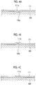
- Fig. 4A to Fig. 4C are schematic views illustrating failure shapes of the member.
- a recessed portion As failure areas that are formed on the surface to be inspected 101 of the member 100, a recessed portion, a protrusion, and a coating failure can be considered.
- a recessed portion 100a is formed on the surface of the member 100 as illustrated in Fig. 4A
- a recessed portion 111a is still shown on the surface even after an underlying coating 111 of a certain thickness is provided.
- a protrusion 100b is formed on the surface of the member 100 as illustrated in Fig. 4B
- a protrusion 111b is still shown on the surface even after the underlying coating 111 of a certain thickness is provided.
- the surface of the member 100 is flat as illustrated in Fig. 4C , if the underlying coating 111 of a certain thickness is not provided, a fine protrusion and recessed portion 111c is shown on the surface.
- the failure detection device 13 detects the recessed portion 111a, the protrusion 111b, and the protrusion and recessed portion 111c as failure areas on the basis of the photographed image picked up by means of the image pickup device 12.
- the determining device 14 determines whether the failure area detected by means of the failure detection device 13 is the recessed portion 111a or a different failure, that is, the protrusion 111b or the protrusion and recessed portion 111c.
- the irradiation device 11 radiates light on the surface to be inspected 101 of the member 100 at a predetermined irradiation angle
- protrusions and recesses on the surface to be inspected 101 are shown as shade and shadow.
- the image pickup device 12 picks up an image of the shade and shadow formed by the protrusions and the recesses and outputs the image to the control device 15.
- the failure detection device 13 detects the shade and shadow by means of, for example, a binarization treatment on the basis of the photographed image picked up by means of the image pickup device 12 and detects a failure area using the size of the shade and shadow.
- the size of the shade and shadow differs due to the length or depth thereof, and thus determining values of the size of shade and shadow that is determined as a failure area are set in advance by means of experiments.
- the failure detection device 13 detects a subject as a failure area when the size of the shade and shadow is larger than the determining value.
- the determining device 14 carries out a determining treatment of the recessed portion 111a, the protrusion 111b, or the protrusion and recessed portion 111c depending on the shape or size of the shade and shadow detected as a failure area by means of the failure detection device 13. Specifically, between the recessed portion 111a and the protrusion 111b, the shape of shade and shadow differs. In addition, among the recessed portion 111a, the protrusion 111b, and the protrusion and recessed portion 111c, the size or number of shade and shadow differs. In this case as well, determining values of the sizes differentiating the recessed portion 111a, the protrusion 111b, and the protrusion and recessed portion 111c are set in advance by means of experiments.
- the determining device 14 determines a subject as the recessed portion 111a or the protrusion 111b when the size of shade and shadow is larger than the determining value or determines a subject as the protrusion and recessed portion 111c when the protrusion and recess shape continues in the shade and shadow.
- the display device 16 is connected to the control device 15.
- the display device 16 displays the failure area detected by the failure detection device 13 and the recessed portion 111a, the protrusion 111b, or the protrusion and recessed portion 111c determined by the determining device 14.
- a worker checks whether or not the repairing of the member 100 is required from the displayed contents of the display device 16.
- the multi-jointed robot 17 is mounted in the moving body 24.
- the multi-jointed robot 17 has a multi-jointed arm 41, and a repairing material supply gun (repairing material supply device) 42 and a marking gun (marking device) 43 are mounted in the tip portion of the multi-jointed arm 41.
- the repairing material supply gun 42 is capable of supplying an underlying coating material (repairing material) to the recessed portion 111a by means of spraying.
- the marking gun 43 is capable of spraying a marking material and carrying out marking the protrusion 111b or the protrusion and recessed portion 111c.
- the control device 15 is capable of controlling the multi-jointed robot 17 depending on the determination result of the determining device 14.
- the control device 15 supplies an underlying coating material to the recessed portion 111a using the repairing material supply gun 42.
- the control device 15 supplies a marking material to the protrusion 111b or the protrusion and recessed portion 111c using the marking gun 43.
- the control device 15 supplies an underlying coating material to the recessed portion 111a using the repairing material supply gun 42 in an amount larger than the volume of the recessed portion 111a.
- the maximum volume of the recessed portion 111a that is formed as a failure area is found out by means of experiments or the like, the regulation amount to be supplied is set, and the repairing material supply gun 42 supplies the regulation amount of an underlying coating material to the recessed portion 111a.
- the control device 15 may estimate the volume of the recessed portion 111a from the size of the shade and shadow, set the regulation amount to be supplied from the estimated volume of the recessed portion 111a, and supply the regulation amount of an underlying coating material to the recessed portion 111a using the repairing material supply gun 42.
- Fig. 3 is a flowchart illustrating the member inspection method
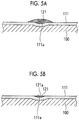
- Fig. 5A and Fig. 5B are schematic views illustrating a member repairing work.
- the member repairing method of the present embodiment has a step of irradiating the surface to be inspected 101 of the member 100 with light, a step of picking up an image of a light-irradiated portion, a step of detecting a failure area on the basis of a photographed image, a step of determining whether or not the failure area is the recessed portion 111a, a step of supplying an underlying coating material to the recessed portion 111a when the failure area is the recessed portion 111a, and a step of supplying a marking material to the failure area when the failure area is not the recessed portion 111a.
- Step S11 a failure detection treatment is carried out on the surface to be inspected 101 which is a surface of the member 100 provided with an underlying coating. That is, the moving body 24 is moved at a predetermined speed with respect to the support board 21, at this time, the irradiation device 11 irradiates the surface to be inspected 101 of the member 100 with light, and the image pickup device 12 picks up an image of this light-irradiated portion, and a photographed image is output to the control device 15 through the input and output portion 33.
- Step S12 the failure detection device 13 detects a failure area on the basis of the photographed image.
- the failure detection device 13 does not detect any failure area (No)
- the process does not follow the routine without doing anything.
- the failure detection device 13 detects a failure area (Yes)
- the determining device 14 determines whether or not the detected failure area is the recessed portion 111a.
- the control device 15 supplies an underlying coating material to the recessed portion 111a using the repairing material supply gun 42.
- the repairing material supply gun 42 sprays an underlying coating material toward the recessed portion 111a, whereby an underlying coating material 121 fills the inside of the recessed portion 111a, and the recessed portion falls in a heaped state.
- Step S15 a surface processing treatment of the surface to be inspected 101 of the member 100 is carried out, whereby the underlying coating material 121 protruding from the recessed portion 111a is removed, and a surface 121a of the underlying coating material 121 becomes equal to the surface of the member 100 as illustrated in Fig. 5B .
- Step S13 when the determining device 14 determines that the failure area is not the recessed portion 111a (No), in Step S16, the control device 15 supplies a marking material to the protrusion 111b or the protrusion and recessed portion 111c using the marking gun 43.
- Step S17 a repairing treatment is carried out on the failure area.
- the protruding underlying coating material is removed from the protrusion portion 111b, thereby making the protrusion portion even with the surface of the member 100.
- an underlying coating material is applied to the protrusion and recessed portion 111c as necessary, and the surface is polished, thereby making the protrusion and recessed portion even with the surface of the member 100.
- the irradiation device 11 that irradiates the surface to be inspected 101 of the member 100 with light
- the image pickup device 12 that picks up an image of the light-irradiated portion on the surface to be inspected 101
- the failure detection device 13 that detects a failure area on the basis of a photographed image picked up by means of the image pickup device 12
- the determining device 14 that classifies the shape of the failure area detected by means of the failure detection device 13 are provided.
- the image pickup device 12 picks up an image of the light-irradiated portion on the surface to be inspected 101
- the failure detection device 13 detects a failure area on the basis of a photographed image
- the determining device 14 classifies the shape of the failure area. Therefore, it is possible to carry out different marking or the like depending on the shape of the failure area, the worker can carry out the optimal repairing treatment suitable for the shape of the failure area by specifying the shape of the failure area, and consequently, it is possible to improve the working efficiency in an inspection work or a repairing work.
- the repairing material supply gun 42 that supplies the underlying coating material 121 as a repairing material is provided, and, when the failure area is determined to be the recessed portion 111a, the control device 15 supplies the underlying coating material 121 to the recessed portion 111a using the repairing material supply gun 42. Therefore, the worker can repair the failure area simply by arranging the shape of the underlying coating material 121 supplied to the recessed portion 111a, and it is possible to improve the working efficiency in a repairing work.
- the control device 15 supplies the underlying coating material 121 to the recessed portion 111a using the repairing material supply gun 42 in an amount larger than the volume of the recessed portion 111a. Therefore, the worker can repair the failure area simply by removing the underlying coating material 121 raised from the recessed portion 111a, and it is possible to improve the working efficiency in a repairing work.
- the control device 15 measures the volume of the recessed portion 111a and supplies the underlying coating material 121 to the recessed portion 111a in an amount equal to or larger than the volume of the recessed portion 111a using the repairing material supply gun 42. Therefore, there is no case in which the underlying coating material 121 is insufficient or excessive compared to the recessed portion 111a, and the worker can easily repair the failure area within a short period of time simply by arranging the shape of the recessed portion 111a.
- the marking gun 43 that carries out marking on the failure area is provided, and, when the failure area is determined to be not the recessed portion 111a, the control device 15 carries out marking on the failure area using the marking gun 43. Therefore, the worker can specify that the failure area has a failure shape other than the recessed portion 111a and can rapidly carry out the optimal repairing treatment suitable for the shape of the failure area.
- the member repairing method of the present embodiment has the step of irradiating the surface to be inspected 101 of the member 100 with light, the step of picking up an image of a light-irradiated portion, the step of detecting a failure area on the basis of a photographed image, the step of determining whether or not the failure area is the recessed portion 111a, and the step of supplying the underlying coating material 121 to the recessed portion 111a when the failure area is the recessed portion 111a.
- the worker simply needs to arrange the shape of the underlying coating material 121 supplied to the recessed portion 111a which is the failure area, and consequently, it is possible to improve the working efficiency in an inspection work or a repairing work.
- the underlying coating material 121 is used as the repairing material, but the present invention is not limited to this constitution, and a repairing material of a material that is different from the underlying coating material 121 may be used.
- the inspection is carried out on the surface to be inspected 101 of the member 100 which has been provided with the underlying coating, but the inspection may be carried out on the surface to be inspected 101 of the member 100 which has not yet been provided with the underlying coating, or the inspection is carried out on the surface to be inspected 101 of the member 100 which has been provided with the primary coating.
- the member 100 is mounted on the support board 21, the moving body 24 in which the irradiation device 11 and the image pickup device 12 are mounted is moved with respect to the support board 21, and, at this time, the inspection is carried out on the surface to be inspected 101 of the member 100, but present invention is not limited to this constitution.
- the inspection may be carried out on the surface to be inspected 101 by immovably fixing the supporting member 27 in which the irradiation device 11 and the image pickup device 12 are mounted, mounting the member 100 on the moving body 24 provided on the support board 21, and moving the member 100.
Landscapes
- Physics & Mathematics (AREA)
- General Physics & Mathematics (AREA)
- General Health & Medical Sciences (AREA)
- Life Sciences & Earth Sciences (AREA)
- Chemical & Material Sciences (AREA)
- Analytical Chemistry (AREA)
- Biochemistry (AREA)
- Health & Medical Sciences (AREA)
- Immunology (AREA)
- Pathology (AREA)
- Engineering & Computer Science (AREA)
- Computer Vision & Pattern Recognition (AREA)
- Signal Processing (AREA)
- Textile Engineering (AREA)
- Mathematical Physics (AREA)
- Investigating Materials By The Use Of Optical Means Adapted For Particular Applications (AREA)
- Length Measuring Devices By Optical Means (AREA)
- Application Of Or Painting With Fluid Materials (AREA)
Abstract
Description
- The present invention relates to a member inspection device for inspecting failures on surfaces of a variety of members constituting aircrafts, cars, or the like and a member repairing method that repairs detected failure portions.
- Examples of the variety of members constituting aircrafts, cars, or the like include metal members, resin members, complex material members, and underlying coating and primary coating are carried out on the surfaces thereof after the members are processed to an intended shape. At this time, an inspection of whether or not there is a failure area on the surfaces of the members is carried out after the underlying coating or the primary coating. This inspection is carried out by a worker visually checking the coated surfaces of the members.
- However, an inspection work visually carried out by a worker on a number of members individually is heavy labor, puts a heavy burden on the worker, and also extends work hours, which deteriorates the working efficiency. Therefore, automation of an inspection work of members is described in, for example, PTL 1. In a processing method of a work described in PTL 1, an inspection robot and a processing robot are respectively disposed in an inspection station in a conveyance line through which the work is conveyed and a processing station downstream of the inspection station, the inspection robot inspects the surface state of the work, and the inspection robot carries out marking on a processed portion in which a detected process is required.
- [PTL 1] Japanese Unexamined Patent Application Publication No.
S62-279931 - In the above-described processing method of a work of PTL 1, the surface state of the work is inspected, and marking is carried out on a processed portion in which a detected process is required. However, for the processed portion in the work in which a process is required, a repairing method differs depending on the failure shape. For example, in a case in which the failure shape is a recessed portion shape, it is necessary to fill the recessed portion with a repairing material, and, in a case in which the failure shape is a protrusion shape, it is necessary to remove the protrusion by wearing. Therefore, in a case in which only marking is carried out on the processed portion in the work in which a process is required, afterwards, the worker needs to check the shape of the marked processed portion and select a repairing work, which creates a problem of a poor working efficiency.
- The present invention has solved the above-described problem, and an object of the present invention is to provide a member inspection device and a member repairing method which improve the working efficiency in an inspection work or a repairing work.
- A member inspection device of the present invention for achieving the above-described object includes an irradiation device that irradiates a surface to be inspected of a member with light, an image pickup device that picks up an image of an irradiated portion of the light on the surface to be inspected, a failure detection device that detects a failure area on the basis of a photographed image picked up by means of the image pickup device, and a determining device that classifies the shape of the failure area detected by means of the failure detection device.
- Therefore, when the irradiation device irradiates the surface to be inspected of the member with light, the image pickup device picks up an image of the light-irradiated portion on the surface to be inspected, the failure detection device detects a failure area on the basis of the photographed image, and the determining device classifies the shape of the failure area. Therefore, it is possible to carry out marking or the like which differs depending on the shape of the failure area, and the worker can carry out the optimal repairing treatment suitable for the shape of the failure area by specifying the shape of the failure area, and consequently, it is possible to improve the working efficiency in an inspection work or a repairing work.
- In the member inspection device of the present invention, a repairing material supply device that supplies a repairing material is provided, and, when the failure area is determined to be a recessed portion by the determining device, the repairing material supply device supplies a repairing material to the recessed portion.
- Therefore, when the failure area is a recessed portion, the repairing material supply device supplies a repairing material to the recessed portion, and thus the worker can repair the failure area simply by arranging the shape of the repairing material supplied to the recessed portion, and it is possible to improve the working efficiency in a repairing work.
- In the member inspection device of the present invention, when the failure area is determined to be a recessed portion by the determining device, the repairing material supply device supplies a repairing material to the recessed portion in an amount larger than a volume of the recessed portion.
- Therefore, when the failure area is a recessed portion, the repairing material supply device supplies a repairing material to the recessed portion in an amount larger than the volume of the recessed portion, and thus the worker can repair the failure area simply by removing the repairing material raised from the recessed portion, and it is possible to improve the working efficiency in a repairing work.
- In the member inspection device of the present invention, when the failure area is determined to be a recessed portion by the determining device, a volume of the recessed portion is measured, and the repairing material supply device supplies a repairing material to the recessed portion in an amount equal to or larger than the volume of the recessed portion.
- Therefore, when the failure area is a recessed portion, the repairing material supply device supplies a repairing material to the recessed portion in an amount equal to or larger than the volume of the recessed portion, and thus there is no case in which the repairing material is insufficient or excessive compared to the recessed portion, and the worker can easily repair the failure area within a short period of time simply by arranging the shape of the recessed portion.
- In the member inspection device of the present invention, a marking device that carries out marking on the failure area is provided, and, when the failure area is determined to be not a recessed portion by the determining device, the marking device carries out marking on the failure area.
- Therefore, when the failure area is not a recessed portion, the worker can specify that the failure area has a failure shape other than a recessed portion by carrying out marking on the failure area and can rapidly carry out the optimal repairing treatment suitable for the shape of the failure area.
- In addition, a member repairing method of the present invention has a step of irradiating a surface to be inspected of a member with light, a step of picking up an image of an irradiated portion with the light, a step of detecting a failure area on the basis of a photographed image, a step of determining whether or not the failure area is a recessed portion, and a step of supplying a repairing material to the recessed portion when the failure area is the recessed portion.
- Therefore, the surface to be inspected of the member is irradiated with light, an image of the light-irradiated portion on the surface to be inspected is picked up, a failure area is detected on the basis of a photographed image, and, when the failure area is a recessed portion, a repairing material is supplied to this recessed portion. Therefore, the worker simply needs to arrange the shape of the repairing material supplied to the recessed portion which is the failure area, and consequently, it is possible to improve the working efficiency in an inspection work or a repairing work.
- According to the member inspection device and the member repairing method of the present invention, a failure area on a surface to be inspected of a member is detected, and a shape of the failure area is classified, and thus the worker can carry out the optimal repairing treatment suitable for the shape of the failure area by specifying the shape of the failure area, and consequently, it is possible to improve the working efficiency in an inspection work or a repairing work.
-
-
Fig. 1 is a plan view illustrating a member inspection device of the present embodiment. -
Fig. 2 is a front view illustrating the member inspection device. -
Fig. 3 is a flowchart illustrating a member inspection method. -
Fig. 4A is a schematic view illustrating a failure shape of a member. -
Fig. 4B is a schematic view illustrating a failure shape of the member. -
Fig. 4C is a schematic view illustrating a failure shape of the member. -
Fig. 5A is a schematic view illustrating a member repairing work. -
Fig. 5B is a schematic view illustrating a member repairing work. - Hereinafter, a preferred embodiment of a member inspection device and a member repairing method of the present invention will be described in detail with reference to the accompanying drawings. Meanwhile, the present invention is not limited by this embodiment, and, in a case in which there is a plurality of embodiments, a combination of the respective embodiments is also considered to be in the scope of the present invention.
-
Fig. 1 is a plan view illustrating a member inspection device of the present embodiment, andFig. 2 is a front view illustrating the member inspection device. - In the present embodiment, a
member inspection device 10 is a device that inspects a failure area on a surface to be inspected (surface) 101 of amember 100 as illustrated inFig. 1 andFig. 2 . Themember 100 is turned into a product by providing an underlying coating on the surface and then providing a primary coating thereon. Themember inspection device 10 of the present embodiment detects a failure area on the surface of themember 100 on which underlying coating has been provided. Themember inspection device 10 includes anirradiation device 11, animage pickup device 12, acontrol device 15 having afailure detection device 13 and a determiningdevice 14, adisplay device 16, and amulti-jointed robot 17. - A
support board 21 is installed parallel to a floor surface, aflat support surface 22 is formed on an upper surface portion, and themember 100 to be inspected can be mounted on thesupport surface 22. In addition, thesupport board 21 hasguide rails 23 fixed along the longitudinal direction (X direction) on both sides in the width direction (Y direction). A movingbody 24 forms a frame shape in a planar view and hasleg portions 25 respectively provided on both sides in the width direction (Y direction), and guide members (for example, rollers) 26 respectively provided in the lower end portions of therespective leg portions 25 are movable along theguide rails 23. Therefore, themoving body 24 is movable along the support board 21 (in the X direction). - A supporting
member 27 is fixed to the central portion of the movingbody 24 and is movable integrally with the movingbody 24. In the supportingmember 27, theirradiation device 11 and theimage pickup device 12 are mounted. Theirradiation device 11 is a device that irradiates the surface to be inspected 101 of themember 100 with light. In this case, theirradiation device 11 is capable of irradiating the entire region of the surface to be inspected 101 of themember 100 with light. - The
irradiation device 11 is constituted of a plurality (two in the present embodiment) ofilluminators illuminators member 27. Theilluminators illuminator 31 is fixed to one side portion of the supportingmember 27 in the Y direction and is capable of radiating light toward thesupport surface 22 at a predetermined irradiation angle toward the other side portion in the Y direction. Theilluminator 32 is fixed to one side portion of the supportingmember 27 in the X direction and is capable of radiating light toward thesupport surface 22 at a predetermined irradiation angle toward the other side portion in the X direction. - The
image pickup device 12 is a device that picks up an image of a light-irradiated portion on the surface to be inspected 101. Theimage pickup device 12 is provided in the lower portion of the supportingmember 27. In this case, theimage pickup device 12 is capable of picking up an image across the entire region of the surface to be inspected 101 of themember 100. Theimage pickup device 12 is one (or the number thereof may be plural) line camera and picks up an image of the light-irradiated portion on the surface to be inspected 101. - Therefore, when the
irradiation device 11 radiates light across the entire region of the surface to be inspected 101 of themember 100 at a predetermined irradiation angle, if there are recesses and protrusions on the surface to be inspected 101, the recesses and the protrusions are shown as shade and shadow. Theimage pickup device 12 picks up an image of the light-irradiated portion on the surface to be inspected 101 and thus picks up an image of shade and shadow generated by the protrusions and the recesses. - In the supporting
member 27, an input andoutput portion 33 of theirradiation device 11 and theimage pickup device 12 is provided. The input andoutput portion 33 is connected to thecontrol device 15 through a cable or wirelessly and is capable of communicating a variety of data. - The
control device 15 has thefailure detection device 13 and the determiningdevice 14. Thefailure detection device 13 is a device that detects a failure area on the basis of a photographed image picked up by means of theimage pickup device 12, and the determiningdevice 14 classifies the shape of the failure area detected by means of thefailure detection device 13. -
Fig. 4A to Fig. 4C are schematic views illustrating failure shapes of the member. As failure areas that are formed on the surface to be inspected 101 of themember 100, a recessed portion, a protrusion, and a coating failure can be considered. When a recessedportion 100a is formed on the surface of themember 100 as illustrated inFig. 4A , a recessedportion 111a is still shown on the surface even after anunderlying coating 111 of a certain thickness is provided. In addition, when aprotrusion 100b is formed on the surface of themember 100 as illustrated inFig. 4B , aprotrusion 111b is still shown on the surface even after theunderlying coating 111 of a certain thickness is provided. Furthermore, when the surface of themember 100 is flat as illustrated inFig. 4C , if theunderlying coating 111 of a certain thickness is not provided, a fine protrusion and recessedportion 111c is shown on the surface. - The
failure detection device 13 detects the recessedportion 111a, theprotrusion 111b, and the protrusion and recessedportion 111c as failure areas on the basis of the photographed image picked up by means of theimage pickup device 12. In addition, the determiningdevice 14 determines whether the failure area detected by means of thefailure detection device 13 is the recessedportion 111a or a different failure, that is, theprotrusion 111b or the protrusion and recessedportion 111c. - Specifically, when the
irradiation device 11 radiates light on the surface to be inspected 101 of themember 100 at a predetermined irradiation angle, protrusions and recesses on the surface to be inspected 101 are shown as shade and shadow. Theimage pickup device 12 picks up an image of the shade and shadow formed by the protrusions and the recesses and outputs the image to thecontrol device 15. Thefailure detection device 13 detects the shade and shadow by means of, for example, a binarization treatment on the basis of the photographed image picked up by means of theimage pickup device 12 and detects a failure area using the size of the shade and shadow. In this case, among the recessedportion 111a, theprotrusion 111b, and the protrusion and recessedportion 111c, the size of the shade and shadow differs due to the length or depth thereof, and thus determining values of the size of shade and shadow that is determined as a failure area are set in advance by means of experiments. Thefailure detection device 13 detects a subject as a failure area when the size of the shade and shadow is larger than the determining value. - The determining
device 14 carries out a determining treatment of the recessedportion 111a, theprotrusion 111b, or the protrusion and recessedportion 111c depending on the shape or size of the shade and shadow detected as a failure area by means of thefailure detection device 13. Specifically, between the recessedportion 111a and theprotrusion 111b, the shape of shade and shadow differs. In addition, among the recessedportion 111a, theprotrusion 111b, and the protrusion and recessedportion 111c, the size or number of shade and shadow differs. In this case as well, determining values of the sizes differentiating the recessedportion 111a, theprotrusion 111b, and the protrusion and recessedportion 111c are set in advance by means of experiments. The determiningdevice 14 determines a subject as the recessedportion 111a or theprotrusion 111b when the size of shade and shadow is larger than the determining value or determines a subject as the protrusion and recessedportion 111c when the protrusion and recess shape continues in the shade and shadow. - The
display device 16 is connected to thecontrol device 15. Thedisplay device 16 displays the failure area detected by thefailure detection device 13 and the recessedportion 111a, theprotrusion 111b, or the protrusion and recessedportion 111c determined by the determiningdevice 14. A worker checks whether or not the repairing of themember 100 is required from the displayed contents of thedisplay device 16. - In addition, in the
member inspection device 10, themulti-jointed robot 17 is mounted in the movingbody 24. Themulti-jointed robot 17 has amulti-jointed arm 41, and a repairing material supply gun (repairing material supply device) 42 and a marking gun (marking device) 43 are mounted in the tip portion of themulti-jointed arm 41. The repairingmaterial supply gun 42 is capable of supplying an underlying coating material (repairing material) to the recessedportion 111a by means of spraying. The markinggun 43 is capable of spraying a marking material and carrying out marking theprotrusion 111b or the protrusion and recessedportion 111c. - That is, the
control device 15 is capable of controlling themulti-jointed robot 17 depending on the determination result of the determiningdevice 14. When the failure area is the recessedportion 111a, thecontrol device 15 supplies an underlying coating material to the recessedportion 111a using the repairingmaterial supply gun 42. On the other hand, when the failure area is theprotrusion 111b or the protrusion and recessedportion 111c, thecontrol device 15 supplies a marking material to theprotrusion 111b or the protrusion and recessedportion 111c using the markinggun 43. - In this case, when the failure area determined by means of the determining
device 14 is the recessedportion 111a, thecontrol device 15 supplies an underlying coating material to the recessedportion 111a using the repairingmaterial supply gun 42 in an amount larger than the volume of the recessedportion 111a. In this case, the maximum volume of the recessedportion 111a that is formed as a failure area is found out by means of experiments or the like, the regulation amount to be supplied is set, and the repairingmaterial supply gun 42 supplies the regulation amount of an underlying coating material to the recessedportion 111a. In addition, when the failure area determined by means of the determiningdevice 14 is the recessedportion 111a, thecontrol device 15 may estimate the volume of the recessedportion 111a from the size of the shade and shadow, set the regulation amount to be supplied from the estimated volume of the recessedportion 111a, and supply the regulation amount of an underlying coating material to the recessedportion 111a using the repairingmaterial supply gun 42. - Here, a member repairing method of the present embodiment will be described using a flowchart of
Fig. 3. Fig. 3 is a flowchart illustrating the member inspection method, andFig. 5A and Fig. 5B are schematic views illustrating a member repairing work. - The member repairing method of the present embodiment has a step of irradiating the surface to be inspected 101 of the
member 100 with light, a step of picking up an image of a light-irradiated portion, a step of detecting a failure area on the basis of a photographed image, a step of determining whether or not the failure area is the recessedportion 111a, a step of supplying an underlying coating material to the recessedportion 111a when the failure area is the recessedportion 111a, and a step of supplying a marking material to the failure area when the failure area is not the recessedportion 111a. - As illustrated in
Fig. 3 , in Step S11, a failure detection treatment is carried out on the surface to be inspected 101 which is a surface of themember 100 provided with an underlying coating. That is, the movingbody 24 is moved at a predetermined speed with respect to thesupport board 21, at this time, theirradiation device 11 irradiates the surface to be inspected 101 of themember 100 with light, and theimage pickup device 12 picks up an image of this light-irradiated portion, and a photographed image is output to thecontrol device 15 through the input andoutput portion 33. - In Step S12, the
failure detection device 13 detects a failure area on the basis of the photographed image. Here, when thefailure detection device 13 does not detect any failure area (No), the process does not follow the routine without doing anything. On the other hand, when thefailure detection device 13 detects a failure area (Yes), in Step S13, the determiningdevice 14 determines whether or not the detected failure area is the recessedportion 111a. Here, when the determiningdevice 14 determines the failure area as the recessedportion 111a (Yes), in Step S14, thecontrol device 15 supplies an underlying coating material to the recessedportion 111a using the repairingmaterial supply gun 42. - That is, as illustrated in
Fig. 5A , the repairingmaterial supply gun 42 sprays an underlying coating material toward the recessedportion 111a, whereby anunderlying coating material 121 fills the inside of the recessedportion 111a, and the recessed portion falls in a heaped state. In addition, in Step S15, a surface processing treatment of the surface to be inspected 101 of themember 100 is carried out, whereby theunderlying coating material 121 protruding from the recessedportion 111a is removed, and asurface 121a of theunderlying coating material 121 becomes equal to the surface of themember 100 as illustrated inFig. 5B . - On the other hand, in Step S13, when the determining
device 14 determines that the failure area is not the recessedportion 111a (No), in Step S16, thecontrol device 15 supplies a marking material to theprotrusion 111b or the protrusion and recessedportion 111c using the markinggun 43. In addition, in Step S17, a repairing treatment is carried out on the failure area. For example, the protruding underlying coating material is removed from theprotrusion portion 111b, thereby making the protrusion portion even with the surface of themember 100. In addition, an underlying coating material is applied to the protrusion and recessedportion 111c as necessary, and the surface is polished, thereby making the protrusion and recessed portion even with the surface of themember 100. - As described above, in the member inspection device of the present embodiment, the
irradiation device 11 that irradiates the surface to be inspected 101 of themember 100 with light, theimage pickup device 12 that picks up an image of the light-irradiated portion on the surface to be inspected 101, thefailure detection device 13 that detects a failure area on the basis of a photographed image picked up by means of theimage pickup device 12, and the determiningdevice 14 that classifies the shape of the failure area detected by means of thefailure detection device 13 are provided. - Therefore, when the
irradiation device 11 irradiates the surface to be inspected 101 of themember 100 with light, theimage pickup device 12 picks up an image of the light-irradiated portion on the surface to be inspected 101, thefailure detection device 13 detects a failure area on the basis of a photographed image, and the determiningdevice 14 classifies the shape of the failure area. Therefore, it is possible to carry out different marking or the like depending on the shape of the failure area, the worker can carry out the optimal repairing treatment suitable for the shape of the failure area by specifying the shape of the failure area, and consequently, it is possible to improve the working efficiency in an inspection work or a repairing work. - In the member inspection device of the present embodiment, the repairing
material supply gun 42 that supplies theunderlying coating material 121 as a repairing material is provided, and, when the failure area is determined to be the recessedportion 111a, thecontrol device 15 supplies theunderlying coating material 121 to the recessedportion 111a using the repairingmaterial supply gun 42. Therefore, the worker can repair the failure area simply by arranging the shape of theunderlying coating material 121 supplied to the recessedportion 111a, and it is possible to improve the working efficiency in a repairing work. - In the member inspection device of the present embodiment, when the failure area is determined to be the recessed
portion 111a, thecontrol device 15 supplies theunderlying coating material 121 to the recessedportion 111a using the repairingmaterial supply gun 42 in an amount larger than the volume of the recessedportion 111a. Therefore, the worker can repair the failure area simply by removing theunderlying coating material 121 raised from the recessedportion 111a, and it is possible to improve the working efficiency in a repairing work. - In the member inspection device of the present embodiment, when the failure area is determined to be the recessed
portion 111a, thecontrol device 15 measures the volume of the recessedportion 111a and supplies theunderlying coating material 121 to the recessedportion 111a in an amount equal to or larger than the volume of the recessedportion 111a using the repairingmaterial supply gun 42. Therefore, there is no case in which theunderlying coating material 121 is insufficient or excessive compared to the recessedportion 111a, and the worker can easily repair the failure area within a short period of time simply by arranging the shape of the recessedportion 111a. - In the member inspection device of the present embodiment, the marking
gun 43 that carries out marking on the failure area is provided, and, when the failure area is determined to be not the recessedportion 111a, thecontrol device 15 carries out marking on the failure area using the markinggun 43. Therefore, the worker can specify that the failure area has a failure shape other than the recessedportion 111a and can rapidly carry out the optimal repairing treatment suitable for the shape of the failure area. - In addition, the member repairing method of the present embodiment has the step of irradiating the surface to be inspected 101 of the
member 100 with light, the step of picking up an image of a light-irradiated portion, the step of detecting a failure area on the basis of a photographed image, the step of determining whether or not the failure area is the recessedportion 111a, and the step of supplying theunderlying coating material 121 to the recessedportion 111a when the failure area is the recessedportion 111a. - Therefore, the worker simply needs to arrange the shape of the
underlying coating material 121 supplied to the recessedportion 111a which is the failure area, and consequently, it is possible to improve the working efficiency in an inspection work or a repairing work. - Meanwhile, in the above-described embodiment, the
underlying coating material 121 is used as the repairing material, but the present invention is not limited to this constitution, and a repairing material of a material that is different from theunderlying coating material 121 may be used. In addition, in the present embodiment, the inspection is carried out on the surface to be inspected 101 of themember 100 which has been provided with the underlying coating, but the inspection may be carried out on the surface to be inspected 101 of themember 100 which has not yet been provided with the underlying coating, or the inspection is carried out on the surface to be inspected 101 of themember 100 which has been provided with the primary coating. - In addition, in the above-described embodiment, the
member 100 is mounted on thesupport board 21, the movingbody 24 in which theirradiation device 11 and theimage pickup device 12 are mounted is moved with respect to thesupport board 21, and, at this time, the inspection is carried out on the surface to be inspected 101 of themember 100, but present invention is not limited to this constitution. For example, the inspection may be carried out on the surface to be inspected 101 by immovably fixing the supportingmember 27 in which theirradiation device 11 and theimage pickup device 12 are mounted, mounting themember 100 on the movingbody 24 provided on thesupport board 21, and moving themember 100. -
- 10 MEMBER INSPECTION DEVICE
- 11 IRRADIATION DEVICE
- 12 IMAGE PICKUP DEVICE
- 13 FAILURE DETECTION DEVICE
- 14 DETERMINING DEVICE
- 15 CONTROL DEVICE
- 16 DISPLAY DEVICE
- 17 MULTI-JOINTED ROBOT
- 42 REPAIRING MATERIAL SUPPLY GUN (REPAIRING MATERIAL SUPPLY DEVICE)
- 43 MARKING GUN (MARKING DEVICE)
- 100 MEMBER
- 101 SURFACE TO BE INSPECTED
- 111 UNDERLYING COATING (REPAIRING MATERIAL)
- 111a RECESSED PORTION
- 111b PROTRUSION
- 111c PROTRUSION AND RECESSED PORTION
- 121 UNDERLYING COATING MATERIAL (REPAIRING MATERIAL)
Claims (6)
- A member inspection device comprising:an irradiation device that irradiates a surface to be inspected of a member with light;an image pickup device that picks up an image of an irradiated portion of the light on the surface to be inspected;a failure detection device that detects a failure area on the basis of a photographed image picked up by means of the image pickup device; anda determining device that classifies the shape of the failure area detected by means of the failure detection device.
- The member inspection device according to Claim 1,
wherein a repairing material supply device that supplies a repairing material is provided, and, when the failure area is determined to be a recessed portion by the determining device, the repairing material supply device supplies a repairing material to the recessed portion. - The member inspection device according to Claim 2,
wherein, when the failure area is determined to be a recessed portion by the determining device, the repairing material supply device supplies a repairing material to the recessed portion in an amount larger than a volume of the recessed portion. - The member inspection device according to Claim 2,
wherein, when the failure area is determined to be a recessed portion by the determining device, a volume of the recessed portion is measured, and the repairing material supply device supplies a repairing material to the recessed portion in an amount equal to or larger than the volume of the recessed portion. - The member inspection device according to any one of Claims 1 to 4,
wherein a marking device that carries out marking on the failure area is provided, and, when the failure area is determined to be not a recessed portion by the determining device, the marking device carries out marking on the failure area. - A member repairing method comprising:a step of irradiating a surface to be inspected of a member with light;a step of picking up an image of an irradiated portion with the light;a step of detecting a failure area on the basis of a photographed image;a step of determining whether or not the failure area is a recessed portion; anda step of supplying a repairing material to the recessed portion when the failure area is the recessed portion.
Applications Claiming Priority (2)
| Application Number | Priority Date | Filing Date | Title |
|---|---|---|---|
| JP2016045984A JP6685777B2 (en) | 2016-03-09 | 2016-03-09 | Member inspection device and member repair method |
| PCT/JP2017/002153 WO2017154383A1 (en) | 2016-03-09 | 2017-01-23 | Member inspection device and member repairing method |
Publications (3)
| Publication Number | Publication Date |
|---|---|
| EP3388782A1 true EP3388782A1 (en) | 2018-10-17 |
| EP3388782A4 EP3388782A4 (en) | 2019-01-16 |
| EP3388782B1 EP3388782B1 (en) | 2022-11-23 |
Family
ID=59789233
Family Applications (1)
| Application Number | Title | Priority Date | Filing Date |
|---|---|---|---|
| EP17762729.6A Active EP3388782B1 (en) | 2016-03-09 | 2017-01-23 | Member inspection device and member repairing method |
Country Status (4)
| Country | Link |
|---|---|
| US (1) | US10488187B2 (en) |
| EP (1) | EP3388782B1 (en) |
| JP (1) | JP6685777B2 (en) |
| WO (1) | WO2017154383A1 (en) |
Cited By (1)
| Publication number | Priority date | Publication date | Assignee | Title |
|---|---|---|---|---|
| WO2020156839A1 (en) * | 2019-01-30 | 2020-08-06 | Siemens Aktiengesellschaft | Method for capturing a coating of a component, in particular of a machine, the coating being formed from a first material |
Families Citing this family (4)
| Publication number | Priority date | Publication date | Assignee | Title |
|---|---|---|---|---|
| WO2020217338A1 (en) * | 2019-04-24 | 2020-10-29 | 株式会社ニコン | Processing system and inspection system |
| JP7662349B2 (en) * | 2021-02-15 | 2025-04-15 | テルモ株式会社 | Coating layer inspection device and coating layer inspection method |
| KR102934956B1 (en) * | 2021-12-17 | 2026-03-06 | 현대자동차 주식회사 | System and method for sanding automation |
| JP7793090B1 (en) * | 2025-03-07 | 2025-12-26 | 三菱重工業株式会社 | Visual inspection equipment |
Family Cites Families (37)
| Publication number | Priority date | Publication date | Assignee | Title |
|---|---|---|---|---|
| JPS62279931A (en) | 1986-05-29 | 1987-12-04 | レンゴ−株式会社 | Defective detector for single-sided corrugated board |
| US4804562A (en) * | 1987-09-21 | 1989-02-14 | United Technologies Corporation | Method for repairing ceramic casting cores |
| US5237404A (en) * | 1990-06-28 | 1993-08-17 | Mazda Motor Corporation | Inspection apparatus with improved detection of surface defects over large and curved surfaces |
| US5239487A (en) * | 1990-10-24 | 1993-08-24 | International Business Machines Corporation | Computer integrated manufacturing rework apparatus and method |
| JPH04171077A (en) * | 1990-11-06 | 1992-06-18 | Sumitomo Metal Ind Ltd | Automatic repair method and device for painted steel plates |
| JP2995349B2 (en) * | 1991-03-29 | 1999-12-27 | マツダ株式会社 | Lighting device for surface condition inspection |
| RU2108514C1 (en) * | 1992-09-09 | 1998-04-10 | Клок Спринг Компани, Л.П. | Method of repair of pipe |
| JP3172287B2 (en) * | 1992-11-09 | 2001-06-04 | マツダ株式会社 | Film defect detector |
| JP2908695B2 (en) * | 1994-02-15 | 1999-06-21 | 日本ペイント株式会社 | Repair paint and method of repairing bright coating film |
| US5844801A (en) * | 1994-12-08 | 1998-12-01 | Honda Giken Kogyo Kabushiki Kaisha | Method of inspecting and manufacturing vehicle body |
| JP3666946B2 (en) * | 1995-09-19 | 2005-06-29 | 本田技研工業株式会社 | Paint repair line |
| DE19613915C1 (en) * | 1996-04-06 | 1997-08-21 | Daimler Benz Ag | Process for the economical repair of a damaged area on a new exterior paint finish of a motor vehicle |
| JPH1044042A (en) * | 1996-08-05 | 1998-02-17 | Suzuki Motor Corp | Inspection object defect removal device |
| DE19730885A1 (en) * | 1997-07-18 | 1999-01-21 | Audi Ag | Process for the automatic detection of surface defects on body-in-white bodies and device for carrying out the process |
| DE19849802A1 (en) | 1998-10-29 | 2000-05-04 | Volkswagen Ag | Paint defect detection and elimination |
| JP2000337840A (en) * | 1999-05-25 | 2000-12-08 | Chuo Denshi Keisoku Kk | Marking device for inspection |
| US6266138B1 (en) * | 1999-10-12 | 2001-07-24 | Perceptron, Inc. | System and method for detecting defects in a surface of a workpiece |
| US20020132044A1 (en) * | 2001-03-19 | 2002-09-19 | Quarles James H. | Scratch repair procedure |
| US6714831B2 (en) * | 2002-01-24 | 2004-03-30 | Ford Motor Company | Paint defect automated seek and repair assembly and method |
| DE10248943A1 (en) * | 2002-10-21 | 2004-04-29 | Volkswagen Ag | Repair process for limited void in paintwork involves multilaminar painting with first layer of clear lacquer with void only in this layer |
| DE102004007830B4 (en) * | 2004-02-18 | 2007-05-10 | Isra Vision Systems Ag | Method for locating defects and marking system |
| DE102004007828B4 (en) * | 2004-02-18 | 2006-05-11 | Isra Vision Systems Ag | Method and system for inspecting surfaces |
| US7039485B2 (en) * | 2004-03-12 | 2006-05-02 | The Boeing Company | Systems and methods enabling automated return to and/or repair of defects with a material placement machine |
| US7230695B2 (en) * | 2004-07-08 | 2007-06-12 | Asahi Glass Company, Ltd. | Defect repair device and defect repair method |
| US20060164647A1 (en) * | 2005-01-13 | 2006-07-27 | Nagase & Co., Ltd. | Apparatus for marking a defect |
| US7790288B2 (en) * | 2005-08-11 | 2010-09-07 | 3M Innovative Properties Company | Interpenetrating polymer network as coating for metal substrate and method therefor |
| JP2007275699A (en) * | 2006-04-03 | 2007-10-25 | Car Conveni Club Kk | Coating film repairing method, covering material used therefor and repaired automobile |
| WO2008092800A1 (en) * | 2007-01-30 | 2008-08-07 | Akzo Nobel Coatings International B.V. | Automatic paint default repair |
| US20120109660A1 (en) * | 2007-10-23 | 2012-05-03 | Gann Xu | Integrated process and system for cosmetic vehicle repairs |
| AU2011314214A1 (en) * | 2010-09-29 | 2013-05-23 | Aerobotics, Inc. | Novel systems and methods for non-destructive inspection of airplanes |
| US20130129913A1 (en) * | 2011-11-21 | 2013-05-23 | Shenzhen China Star Optoellectronics Technolohy Co., Ltd. | Coating apparatus and coating method |
| US9149835B2 (en) * | 2013-02-28 | 2015-10-06 | Ppg Industries Ohio, Inc. | Methods for repairing defects in automotive coatings |
| US9409206B2 (en) * | 2013-05-02 | 2016-08-09 | The Boeing Company | Methods and systems for applying aerodynamically functional coatings to a surface |
| JP2015160184A (en) * | 2014-02-28 | 2015-09-07 | 日産自動車株式会社 | How to repair matte paint film |
| EP3135442B1 (en) * | 2015-08-26 | 2018-12-19 | Airbus Operations GmbH | Robot system and method of operating a robot system |
| US20170148101A1 (en) * | 2015-11-23 | 2017-05-25 | CSI Holdings I LLC | Damage assessment and repair based on objective surface data |
| KR101855778B1 (en) * | 2016-12-06 | 2018-05-09 | 현대자동차 주식회사 | Vehicle body flaw elimination method using virtual marking, and the system thereof |
-
2016
- 2016-03-09 JP JP2016045984A patent/JP6685777B2/en active Active
-
2017
- 2017-01-23 US US16/070,935 patent/US10488187B2/en active Active
- 2017-01-23 WO PCT/JP2017/002153 patent/WO2017154383A1/en not_active Ceased
- 2017-01-23 EP EP17762729.6A patent/EP3388782B1/en active Active
Cited By (1)
| Publication number | Priority date | Publication date | Assignee | Title |
|---|---|---|---|---|
| WO2020156839A1 (en) * | 2019-01-30 | 2020-08-06 | Siemens Aktiengesellschaft | Method for capturing a coating of a component, in particular of a machine, the coating being formed from a first material |
Also Published As
| Publication number | Publication date |
|---|---|
| EP3388782B1 (en) | 2022-11-23 |
| JP2017161354A (en) | 2017-09-14 |
| EP3388782A4 (en) | 2019-01-16 |
| US20190041199A1 (en) | 2019-02-07 |
| WO2017154383A1 (en) | 2017-09-14 |
| JP6685777B2 (en) | 2020-04-22 |
| US10488187B2 (en) | 2019-11-26 |
Similar Documents
| Publication | Publication Date | Title |
|---|---|---|
| US10488187B2 (en) | Member inspection device and member repairing method | |
| EP3640584A1 (en) | Inspection device | |
| CN211576098U (en) | Thickness detection system | |
| EP3480552B1 (en) | Apparatus for inspecting precision countersinks in aircraft structures by machine vision | |
| JPWO2020090962A5 (en) | ||
| US11707842B2 (en) | Robot system and coordinate conversion method | |
| IT201800004368A1 (en) | System for identifying defects on a surface of at least a portion of a body and its method | |
| US20060049158A1 (en) | Method and apparatus for regulating an automatic treatment process | |
| CA3194506A1 (en) | Method and apparatus for automated quality control for cutting machines of flexible material parts | |
| MX2021014453A (en) | Method for coordinating an identification and the processing of a defect of a workpiece, and device for carrying out the method. | |
| US20150254833A1 (en) | Programmable Digital Machine Vision Inspection System | |
| JP2002508071A (en) | Method for automatically recognizing body shell surface defects and apparatus for implementing the method | |
| WO2014046922A1 (en) | Soldering machine | |
| JP2018521861A (en) | Inspection of perforated features in objects | |
| CN115734845A (en) | Workpiece processing device and method for operating a workpiece processing device | |
| JP2008202949A (en) | Defect inspection method and defect inspection apparatus | |
| KR101513407B1 (en) | Finishing assistance apparatus, finishing assistance method and finishing assistance system | |
| KR101754115B1 (en) | Painting product carrying apparatus | |
| ES2632211A1 (en) | Procedure and device for the treatment of flat glass units in a glass processing installation (Machine-translation by Google Translate, not legally binding) | |
| US20150219442A1 (en) | Laser inspection station | |
| KR102784795B1 (en) | Apparatus and method for inspecting surface defects | |
| EP3509409B1 (en) | Component mounting device and position identification method | |
| KR102124726B1 (en) | Vehicle automatic integrated inspection system | |
| KR102356244B1 (en) | Apparatus and method for sealing hotmelt of housing | |
| KR100754511B1 (en) | How to automatically correct the working position of the seat mounting robot of a vehicle using intensive LED lighting |
Legal Events
| Date | Code | Title | Description |
|---|---|---|---|
| STAA | Information on the status of an ep patent application or granted ep patent |
Free format text: STATUS: THE INTERNATIONAL PUBLICATION HAS BEEN MADE |
|
| PUAI | Public reference made under article 153(3) epc to a published international application that has entered the european phase |
Free format text: ORIGINAL CODE: 0009012 |
|
| STAA | Information on the status of an ep patent application or granted ep patent |
Free format text: STATUS: REQUEST FOR EXAMINATION WAS MADE |
|
| 17P | Request for examination filed |
Effective date: 20180713 |
|
| AK | Designated contracting states |
Kind code of ref document: A1 Designated state(s): AL AT BE BG CH CY CZ DE DK EE ES FI FR GB GR HR HU IE IS IT LI LT LU LV MC MK MT NL NO PL PT RO RS SE SI SK SM TR |
|
| AX | Request for extension of the european patent |
Extension state: BA ME |
|
| A4 | Supplementary search report drawn up and despatched |
Effective date: 20181217 |
|
| RIC1 | Information provided on ipc code assigned before grant |
Ipc: G01N 21/84 20060101ALI20181211BHEP Ipc: B05D 3/00 20060101ALI20181211BHEP Ipc: G01B 11/30 20060101AFI20181211BHEP Ipc: B05D 5/06 20060101ALI20181211BHEP Ipc: G01N 21/88 20060101ALI20181211BHEP |
|
| DAV | Request for validation of the european patent (deleted) | ||
| DAX | Request for extension of the european patent (deleted) | ||
| STAA | Information on the status of an ep patent application or granted ep patent |
Free format text: STATUS: EXAMINATION IS IN PROGRESS |
|
| 17Q | First examination report despatched |
Effective date: 20210615 |
|
| GRAP | Despatch of communication of intention to grant a patent |
Free format text: ORIGINAL CODE: EPIDOSNIGR1 |
|
| STAA | Information on the status of an ep patent application or granted ep patent |
Free format text: STATUS: GRANT OF PATENT IS INTENDED |
|
| INTG | Intention to grant announced |
Effective date: 20220915 |
|
| GRAS | Grant fee paid |
Free format text: ORIGINAL CODE: EPIDOSNIGR3 |
|
| GRAA | (expected) grant |
Free format text: ORIGINAL CODE: 0009210 |
|
| STAA | Information on the status of an ep patent application or granted ep patent |
Free format text: STATUS: THE PATENT HAS BEEN GRANTED |
|
| AK | Designated contracting states |
Kind code of ref document: B1 Designated state(s): AL AT BE BG CH CY CZ DE DK EE ES FI FR GB GR HR HU IE IS IT LI LT LU LV MC MK MT NL NO PL PT RO RS SE SI SK SM TR |
|
| REG | Reference to a national code |
Ref country code: GB Ref legal event code: FG4D |
|
| REG | Reference to a national code |
Ref country code: CH Ref legal event code: EP |
|
| REG | Reference to a national code |
Ref country code: AT Ref legal event code: REF Ref document number: 1533380 Country of ref document: AT Kind code of ref document: T Effective date: 20221215 Ref country code: DE Ref legal event code: R096 Ref document number: 602017063943 Country of ref document: DE |
|
| REG | Reference to a national code |
Ref country code: IE Ref legal event code: FG4D |
|
| REG | Reference to a national code |
Ref country code: LT Ref legal event code: MG9D |
|
| REG | Reference to a national code |
Ref country code: NL Ref legal event code: MP Effective date: 20221123 |
|
| REG | Reference to a national code |
Ref country code: AT Ref legal event code: MK05 Ref document number: 1533380 Country of ref document: AT Kind code of ref document: T Effective date: 20221123 |
|
| PG25 | Lapsed in a contracting state [announced via postgrant information from national office to epo] |
Ref country code: SE Free format text: LAPSE BECAUSE OF FAILURE TO SUBMIT A TRANSLATION OF THE DESCRIPTION OR TO PAY THE FEE WITHIN THE PRESCRIBED TIME-LIMIT Effective date: 20221123 Ref country code: PT Free format text: LAPSE BECAUSE OF FAILURE TO SUBMIT A TRANSLATION OF THE DESCRIPTION OR TO PAY THE FEE WITHIN THE PRESCRIBED TIME-LIMIT Effective date: 20230323 Ref country code: NO Free format text: LAPSE BECAUSE OF FAILURE TO SUBMIT A TRANSLATION OF THE DESCRIPTION OR TO PAY THE FEE WITHIN THE PRESCRIBED TIME-LIMIT Effective date: 20230223 Ref country code: LT Free format text: LAPSE BECAUSE OF FAILURE TO SUBMIT A TRANSLATION OF THE DESCRIPTION OR TO PAY THE FEE WITHIN THE PRESCRIBED TIME-LIMIT Effective date: 20221123 Ref country code: FI Free format text: LAPSE BECAUSE OF FAILURE TO SUBMIT A TRANSLATION OF THE DESCRIPTION OR TO PAY THE FEE WITHIN THE PRESCRIBED TIME-LIMIT Effective date: 20221123 Ref country code: ES Free format text: LAPSE BECAUSE OF FAILURE TO SUBMIT A TRANSLATION OF THE DESCRIPTION OR TO PAY THE FEE WITHIN THE PRESCRIBED TIME-LIMIT Effective date: 20221123 Ref country code: AT Free format text: LAPSE BECAUSE OF FAILURE TO SUBMIT A TRANSLATION OF THE DESCRIPTION OR TO PAY THE FEE WITHIN THE PRESCRIBED TIME-LIMIT Effective date: 20221123 |
|
| PG25 | Lapsed in a contracting state [announced via postgrant information from national office to epo] |
Ref country code: RS Free format text: LAPSE BECAUSE OF FAILURE TO SUBMIT A TRANSLATION OF THE DESCRIPTION OR TO PAY THE FEE WITHIN THE PRESCRIBED TIME-LIMIT Effective date: 20221123 Ref country code: PL Free format text: LAPSE BECAUSE OF FAILURE TO SUBMIT A TRANSLATION OF THE DESCRIPTION OR TO PAY THE FEE WITHIN THE PRESCRIBED TIME-LIMIT Effective date: 20221123 Ref country code: LV Free format text: LAPSE BECAUSE OF FAILURE TO SUBMIT A TRANSLATION OF THE DESCRIPTION OR TO PAY THE FEE WITHIN THE PRESCRIBED TIME-LIMIT Effective date: 20221123 Ref country code: IS Free format text: LAPSE BECAUSE OF FAILURE TO SUBMIT A TRANSLATION OF THE DESCRIPTION OR TO PAY THE FEE WITHIN THE PRESCRIBED TIME-LIMIT Effective date: 20230323 Ref country code: HR Free format text: LAPSE BECAUSE OF FAILURE TO SUBMIT A TRANSLATION OF THE DESCRIPTION OR TO PAY THE FEE WITHIN THE PRESCRIBED TIME-LIMIT Effective date: 20221123 Ref country code: GR Free format text: LAPSE BECAUSE OF FAILURE TO SUBMIT A TRANSLATION OF THE DESCRIPTION OR TO PAY THE FEE WITHIN THE PRESCRIBED TIME-LIMIT Effective date: 20230224 |
|
| PG25 | Lapsed in a contracting state [announced via postgrant information from national office to epo] |
Ref country code: NL Free format text: LAPSE BECAUSE OF FAILURE TO SUBMIT A TRANSLATION OF THE DESCRIPTION OR TO PAY THE FEE WITHIN THE PRESCRIBED TIME-LIMIT Effective date: 20221123 |
|
| PG25 | Lapsed in a contracting state [announced via postgrant information from national office to epo] |
Ref country code: SM Free format text: LAPSE BECAUSE OF FAILURE TO SUBMIT A TRANSLATION OF THE DESCRIPTION OR TO PAY THE FEE WITHIN THE PRESCRIBED TIME-LIMIT Effective date: 20221123 Ref country code: RO Free format text: LAPSE BECAUSE OF FAILURE TO SUBMIT A TRANSLATION OF THE DESCRIPTION OR TO PAY THE FEE WITHIN THE PRESCRIBED TIME-LIMIT Effective date: 20221123 Ref country code: EE Free format text: LAPSE BECAUSE OF FAILURE TO SUBMIT A TRANSLATION OF THE DESCRIPTION OR TO PAY THE FEE WITHIN THE PRESCRIBED TIME-LIMIT Effective date: 20221123 Ref country code: DK Free format text: LAPSE BECAUSE OF FAILURE TO SUBMIT A TRANSLATION OF THE DESCRIPTION OR TO PAY THE FEE WITHIN THE PRESCRIBED TIME-LIMIT Effective date: 20221123 Ref country code: CZ Free format text: LAPSE BECAUSE OF FAILURE TO SUBMIT A TRANSLATION OF THE DESCRIPTION OR TO PAY THE FEE WITHIN THE PRESCRIBED TIME-LIMIT Effective date: 20221123 |
|
| REG | Reference to a national code |
Ref country code: DE Ref legal event code: R097 Ref document number: 602017063943 Country of ref document: DE |
|
| PG25 | Lapsed in a contracting state [announced via postgrant information from national office to epo] |
Ref country code: SK Free format text: LAPSE BECAUSE OF FAILURE TO SUBMIT A TRANSLATION OF THE DESCRIPTION OR TO PAY THE FEE WITHIN THE PRESCRIBED TIME-LIMIT Effective date: 20221123 Ref country code: AL Free format text: LAPSE BECAUSE OF FAILURE TO SUBMIT A TRANSLATION OF THE DESCRIPTION OR TO PAY THE FEE WITHIN THE PRESCRIBED TIME-LIMIT Effective date: 20221123 |
|
| REG | Reference to a national code |
Ref country code: CH Ref legal event code: PL |
|
| PG25 | Lapsed in a contracting state [announced via postgrant information from national office to epo] |
Ref country code: LU Free format text: LAPSE BECAUSE OF NON-PAYMENT OF DUE FEES Effective date: 20230123 |
|
| PLBE | No opposition filed within time limit |
Free format text: ORIGINAL CODE: 0009261 |
|
| STAA | Information on the status of an ep patent application or granted ep patent |
Free format text: STATUS: NO OPPOSITION FILED WITHIN TIME LIMIT |
|
| REG | Reference to a national code |
Ref country code: BE Ref legal event code: MM Effective date: 20230131 |
|
| PG25 | Lapsed in a contracting state [announced via postgrant information from national office to epo] |
Ref country code: LI Free format text: LAPSE BECAUSE OF NON-PAYMENT OF DUE FEES Effective date: 20230131 Ref country code: CH Free format text: LAPSE BECAUSE OF NON-PAYMENT OF DUE FEES Effective date: 20230131 |
|
| 26N | No opposition filed |
Effective date: 20230824 |
|
| PG25 | Lapsed in a contracting state [announced via postgrant information from national office to epo] |
Ref country code: SI Free format text: LAPSE BECAUSE OF FAILURE TO SUBMIT A TRANSLATION OF THE DESCRIPTION OR TO PAY THE FEE WITHIN THE PRESCRIBED TIME-LIMIT Effective date: 20221123 Ref country code: BE Free format text: LAPSE BECAUSE OF NON-PAYMENT OF DUE FEES Effective date: 20230131 |
|
| PGFP | Annual fee paid to national office [announced via postgrant information from national office to epo] |
Ref country code: GB Payment date: 20231130 Year of fee payment: 8 |
|
| PG25 | Lapsed in a contracting state [announced via postgrant information from national office to epo] |
Ref country code: IE Free format text: LAPSE BECAUSE OF NON-PAYMENT OF DUE FEES Effective date: 20230123 |
|
| PGFP | Annual fee paid to national office [announced via postgrant information from national office to epo] |
Ref country code: FR Payment date: 20231212 Year of fee payment: 8 |
|
| PGFP | Annual fee paid to national office [announced via postgrant information from national office to epo] |
Ref country code: DE Payment date: 20231128 Year of fee payment: 8 |
|
| PG25 | Lapsed in a contracting state [announced via postgrant information from national office to epo] |
Ref country code: IT Free format text: LAPSE BECAUSE OF FAILURE TO SUBMIT A TRANSLATION OF THE DESCRIPTION OR TO PAY THE FEE WITHIN THE PRESCRIBED TIME-LIMIT Effective date: 20221123 |
|
| PG25 | Lapsed in a contracting state [announced via postgrant information from national office to epo] |
Ref country code: MC Free format text: LAPSE BECAUSE OF FAILURE TO SUBMIT A TRANSLATION OF THE DESCRIPTION OR TO PAY THE FEE WITHIN THE PRESCRIBED TIME-LIMIT Effective date: 20221123 |
|
| PG25 | Lapsed in a contracting state [announced via postgrant information from national office to epo] |
Ref country code: MC Free format text: LAPSE BECAUSE OF FAILURE TO SUBMIT A TRANSLATION OF THE DESCRIPTION OR TO PAY THE FEE WITHIN THE PRESCRIBED TIME-LIMIT Effective date: 20221123 |
|
| PG25 | Lapsed in a contracting state [announced via postgrant information from national office to epo] |
Ref country code: BG Free format text: LAPSE BECAUSE OF FAILURE TO SUBMIT A TRANSLATION OF THE DESCRIPTION OR TO PAY THE FEE WITHIN THE PRESCRIBED TIME-LIMIT Effective date: 20221123 |
|
| PG25 | Lapsed in a contracting state [announced via postgrant information from national office to epo] |
Ref country code: BG Free format text: LAPSE BECAUSE OF FAILURE TO SUBMIT A TRANSLATION OF THE DESCRIPTION OR TO PAY THE FEE WITHIN THE PRESCRIBED TIME-LIMIT Effective date: 20221123 |
|
| PG25 | Lapsed in a contracting state [announced via postgrant information from national office to epo] |
Ref country code: CY Free format text: LAPSE BECAUSE OF FAILURE TO SUBMIT A TRANSLATION OF THE DESCRIPTION OR TO PAY THE FEE WITHIN THE PRESCRIBED TIME-LIMIT; INVALID AB INITIO Effective date: 20170123 |
|
| REG | Reference to a national code |
Ref country code: DE Ref legal event code: R119 Ref document number: 602017063943 Country of ref document: DE |
|
| PG25 | Lapsed in a contracting state [announced via postgrant information from national office to epo] |
Ref country code: HU Free format text: LAPSE BECAUSE OF FAILURE TO SUBMIT A TRANSLATION OF THE DESCRIPTION OR TO PAY THE FEE WITHIN THE PRESCRIBED TIME-LIMIT; INVALID AB INITIO Effective date: 20170123 |
|
| GBPC | Gb: european patent ceased through non-payment of renewal fee |
Effective date: 20250123 |
|
| PG25 | Lapsed in a contracting state [announced via postgrant information from national office to epo] |
Ref country code: DE Free format text: LAPSE BECAUSE OF NON-PAYMENT OF DUE FEES Effective date: 20250801 |
|
| PG25 | Lapsed in a contracting state [announced via postgrant information from national office to epo] |
Ref country code: GB Free format text: LAPSE BECAUSE OF NON-PAYMENT OF DUE FEES Effective date: 20250123 |
|
| PG25 | Lapsed in a contracting state [announced via postgrant information from national office to epo] |
Ref country code: FR Free format text: LAPSE BECAUSE OF NON-PAYMENT OF DUE FEES Effective date: 20250131 |
|
| PG25 | Lapsed in a contracting state [announced via postgrant information from national office to epo] |
Ref country code: TR Free format text: LAPSE BECAUSE OF FAILURE TO SUBMIT A TRANSLATION OF THE DESCRIPTION OR TO PAY THE FEE WITHIN THE PRESCRIBED TIME-LIMIT Effective date: 20221123 |