EP3388704A1 - Selectable one-way clutch - Google Patents
Selectable one-way clutch Download PDFInfo
- Publication number
- EP3388704A1 EP3388704A1 EP18161826.5A EP18161826A EP3388704A1 EP 3388704 A1 EP3388704 A1 EP 3388704A1 EP 18161826 A EP18161826 A EP 18161826A EP 3388704 A1 EP3388704 A1 EP 3388704A1
- Authority
- EP
- European Patent Office
- Prior art keywords
- plate
- protrusion
- selectable
- way clutch
- strut
- Prior art date
- Legal status (The legal status is an assumption and is not a legal conclusion. Google has not performed a legal analysis and makes no representation as to the accuracy of the status listed.)
- Granted
Links
- 230000015572 biosynthetic process Effects 0.000 claims abstract description 7
- 238000005452 bending Methods 0.000 description 9
- 230000004043 responsiveness Effects 0.000 description 7
- 230000009467 reduction Effects 0.000 description 6
- 238000004904 shortening Methods 0.000 description 4
- 230000005540 biological transmission Effects 0.000 description 1
- 239000012141 concentrate Substances 0.000 description 1
- 238000004519 manufacturing process Methods 0.000 description 1
- 238000000034 method Methods 0.000 description 1
- 230000004048 modification Effects 0.000 description 1
- 238000012986 modification Methods 0.000 description 1
- 230000008569 process Effects 0.000 description 1
- 238000005096 rolling process Methods 0.000 description 1
Images






Classifications
-
- F—MECHANICAL ENGINEERING; LIGHTING; HEATING; WEAPONS; BLASTING
- F16—ENGINEERING ELEMENTS AND UNITS; GENERAL MEASURES FOR PRODUCING AND MAINTAINING EFFECTIVE FUNCTIONING OF MACHINES OR INSTALLATIONS; THERMAL INSULATION IN GENERAL
- F16D—COUPLINGS FOR TRANSMITTING ROTATION; CLUTCHES; BRAKES
- F16D41/00—Freewheels or freewheel clutches
- F16D41/12—Freewheels or freewheel clutches with hinged pawl co-operating with teeth, cogs, or the like
- F16D41/16—Freewheels or freewheel clutches with hinged pawl co-operating with teeth, cogs, or the like the action being reversible
-
- F—MECHANICAL ENGINEERING; LIGHTING; HEATING; WEAPONS; BLASTING
- F16—ENGINEERING ELEMENTS AND UNITS; GENERAL MEASURES FOR PRODUCING AND MAINTAINING EFFECTIVE FUNCTIONING OF MACHINES OR INSTALLATIONS; THERMAL INSULATION IN GENERAL
- F16D—COUPLINGS FOR TRANSMITTING ROTATION; CLUTCHES; BRAKES
- F16D41/00—Freewheels or freewheel clutches
- F16D41/06—Freewheels or freewheel clutches with intermediate wedging coupling members between an inner and an outer surface
- F16D41/08—Freewheels or freewheel clutches with intermediate wedging coupling members between an inner and an outer surface with provision for altering the freewheeling action
- F16D41/084—Freewheels or freewheel clutches with intermediate wedging coupling members between an inner and an outer surface with provision for altering the freewheeling action the intermediate coupling members wedging by pivoting or rocking
-
- F—MECHANICAL ENGINEERING; LIGHTING; HEATING; WEAPONS; BLASTING
- F16—ENGINEERING ELEMENTS AND UNITS; GENERAL MEASURES FOR PRODUCING AND MAINTAINING EFFECTIVE FUNCTIONING OF MACHINES OR INSTALLATIONS; THERMAL INSULATION IN GENERAL
- F16D—COUPLINGS FOR TRANSMITTING ROTATION; CLUTCHES; BRAKES
- F16D41/00—Freewheels or freewheel clutches
- F16D41/12—Freewheels or freewheel clutches with hinged pawl co-operating with teeth, cogs, or the like
- F16D41/125—Freewheels or freewheel clutches with hinged pawl co-operating with teeth, cogs, or the like the pawl movement having an axial component
-
- F—MECHANICAL ENGINEERING; LIGHTING; HEATING; WEAPONS; BLASTING
- F16—ENGINEERING ELEMENTS AND UNITS; GENERAL MEASURES FOR PRODUCING AND MAINTAINING EFFECTIVE FUNCTIONING OF MACHINES OR INSTALLATIONS; THERMAL INSULATION IN GENERAL
- F16D—COUPLINGS FOR TRANSMITTING ROTATION; CLUTCHES; BRAKES
- F16D41/00—Freewheels or freewheel clutches
- F16D41/12—Freewheels or freewheel clutches with hinged pawl co-operating with teeth, cogs, or the like
- F16D41/14—Freewheels or freewheel clutches with hinged pawl co-operating with teeth, cogs, or the like the effective stroke of the pawl being adjustable
-
- B—PERFORMING OPERATIONS; TRANSPORTING
- B60—VEHICLES IN GENERAL
- B60Y—INDEXING SCHEME RELATING TO ASPECTS CROSS-CUTTING VEHICLE TECHNOLOGY
- B60Y2400/00—Special features of vehicle units
- B60Y2400/42—Clutches or brakes
- B60Y2400/427—One-way clutches
-
- F—MECHANICAL ENGINEERING; LIGHTING; HEATING; WEAPONS; BLASTING
- F16—ENGINEERING ELEMENTS AND UNITS; GENERAL MEASURES FOR PRODUCING AND MAINTAINING EFFECTIVE FUNCTIONING OF MACHINES OR INSTALLATIONS; THERMAL INSULATION IN GENERAL
- F16D—COUPLINGS FOR TRANSMITTING ROTATION; CLUTCHES; BRAKES
- F16D2500/00—External control of clutches by electric or electronic means
- F16D2500/10—System to be controlled
- F16D2500/104—Clutch
- F16D2500/10443—Clutch type
- F16D2500/10493—One way clutch
-
- Y—GENERAL TAGGING OF NEW TECHNOLOGICAL DEVELOPMENTS; GENERAL TAGGING OF CROSS-SECTIONAL TECHNOLOGIES SPANNING OVER SEVERAL SECTIONS OF THE IPC; TECHNICAL SUBJECTS COVERED BY FORMER USPC CROSS-REFERENCE ART COLLECTIONS [XRACs] AND DIGESTS
- Y02—TECHNOLOGIES OR APPLICATIONS FOR MITIGATION OR ADAPTATION AGAINST CLIMATE CHANGE
- Y02T—CLIMATE CHANGE MITIGATION TECHNOLOGIES RELATED TO TRANSPORTATION
- Y02T10/00—Road transport of goods or passengers
- Y02T10/60—Other road transportation technologies with climate change mitigation effect
- Y02T10/62—Hybrid vehicles
Definitions
- the present invention relates to a selectable one-way clutch.
- US Patent No. 8844693 discloses a selectable one-way clutch that includes a pocket plate having a plurality of pockets (housing recesses) in which struts (engaging tabs) are respectively housed, a notch plate having a plurality of notches (engaging recesses) in which the struts are respectively engaged, and a selector plate located between the pocket plate and the notch plate.
- an "overrun” may occur in which the notch plate rotates in a direction (hereinafter referred to as an "overrun direction") that is opposite from an engaging direction of the selectable one-way clutch, i.e., from a direction in which the struts mesh with the notches.
- the strut behaves so as to hit the pocket plate and the notch plate by swinging up and down therebetween.
- this up-and-down hitting behavior escalates, for example, large yaw moment My and translational fore F1 occur on a strut 52 as shown in FIG. 22 and FIG. 23 .
- a pair of projections (inner projection 522 and outer projection 523) of the strut 52 repeatedly hit an inner surface 11a of a pocket 11 of a pocket plate 10 as shown in parts A of FIG. 22 and parts B of FIG. 23 , which may shorten the life of the strut 52.
- the present invention provides a selectable one-way clutch that can avoid shortening the life of the engaging tab and enhance the durability of the engaging tab.
- An aspect of the present invention is a selectable one-way clutch.
- This selectable one-way clutch includes a pocket plate, engaging tabs, a notch plate, and a selector plate.
- the pocket plate includes a side surface and the side surface has a plurality of housing recesses.
- the engaging tabs are respectively housed in the housing recesses.
- the notch plate is provided so as to be rotatable relative to the pocket plate, and has a plurality of engaging recesses in a surface facing the surface of the pocket plate on the one side.
- the selector plate is located between the pocket plate and the notch plate.
- the selector plate has a plurality of window holes extending therethrough in a plate thickness direction.
- the selector plate is configured to rotate around the same rotational axis as the notch plate so as to switch between a state in which the engaging tab is raised from the pocket plate toward the notch plate through the window hole and a state in which the engaging tab is housed in the housing recess.
- the engaging tab includes a protrusion provided at the center of the engaging tab in the radial direction of the selectable one-way clutch.
- the selector plate has a cutout groove provided so as to extend from the window hole along the formation direction of the protrusion. The cutout groove is fitted on the protrusion, and the engaging tab and the selector plate overlap each other in the rotational axis direction of the selectable one-way clutch when the selectable one-way clutch is disengaged.
- the selectable one-way clutch when the selectable one-way clutch is disengaged (when the selector plate is closed), the distance between the engaging tab and the notch plate in this selectable one-way clutch is smaller than the distance therebetween in the related art. Accordingly, the raised angle of the engaging tab during an overrun in this selectable one-way clutch is smaller than the raised angle in the related art. Therefore, according to this selectable one-way clutch, the speed at which the engaging tab swings down during an overrun is lower than that in the related art, and the force with which the engaging tab hits the notch plate and the pocket plate by swinging up and down therebetween is reduced.
- the engaging tab may include a main body extending along the circumferential direction of the selectable one-way clutch, and a pair of projections extending from opposite sides of the main body along the radial direction from an end of the main body in the circumferential direction, and constituting a rotational axis of the engaging tab when the engaging tab is raised.
- the main body may include the protrusion protruding from the position of an upper surface of the pair of projections. An upper surface of the protrusion may come in contact with the notch plate when the engaging tab is raised from the pocket plate toward the notch plate through the window hole.
- the protrusion may have side surfaces parallel to side surfaces of the main body, and may extend to the end of the main body on the side of the pair of projections, and the engaging tab may include inclined surfaces provided respectively on both sides of the side surfaces of the protrusion and inclined relative to the upper surface of the pair of projections.
- the protrusion is provided so as to extend to the end of the main body, which can enhance the mechanical strength around joint portions between the main body and the pair of projections.
- the protrusion may have side surfaces inclined relative to side surfaces of the main body, and may be tapered toward the end of the main body on the side of the pair of projections, and the engaging tab may include inclined surfaces provided respectively on both sides of the side surfaces of the protrusion and inclined relative to the upper surface of the pair of projections.
- the protrusion has a tapered shape, so that, when the cutout groove of the selector plate is fitted on the protrusion of the engaging tab, the tapered surfaces of the cutout groove and the protrusion come in contact with each other, which can reduce a bending stress occurring on the selector plate when the selector plate is closed. Accordingly, it is possible to enhance the durability of the selector plate and the actuation responsiveness of the engaging tab.
- the inclined surfaces and the protrusion may be located side by side in the radial direction, and the pair of projections and the protrusion may be located side by side in the radial direction.
- the pair of projections and the protrusion are disposed side by side in the radial direction of the selectable one-way clutch, which can enhance the mechanical strength around the joint portions between the main body and the pair of projections.
- the pair of projections, the inclined surfaces, and the protrusion may be located side by side in the radial direction.
- the pair of projections, the inclined surfaces, and the protrusion are disposed side by side in the radial direction of the selectable one-way clutch. Accordingly, it is possible to shorten the cutout groove of the selector plate, and thereby to enhance the rigidity and durability around the cutout groove of the selector plate.
- the inclined surface may have a curved shape from the side surface of the protrusion to the side surface of the main body.
- the inclined surface has a curved shape, so that, when the cutout groove of the selector plate is fitted on the protrusion, a lower surface of the selector plate and an inner surface of the window hole slide over the inclined surfaces of the engaging tab while all the time remaining in line contact therewith. Accordingly, it is possible to reduce the contact pressure between the selector plate and the engaging tab, and thereby to enhance the wear resistance of the selector plate and the engaging tab.
- the inclined surface may include a flat contact portion parallel to a lower surface of the selector plate.
- the flat contact portion may be provided at a position within the inclined surface at which the lower surface of the selector plate comes in contact when the selectable one-way clutch is disengaged.
- the angle of the inclined surface relative to a lower surface of the selector plate may be larger than the angle of an upper surface of the engaging tab relative to the lower surface of the selector plate.
- the driving angle of an arm that actuates the selector plate can be reduced. Accordingly, it is possible to reduce the driving force of the actuator that rotates the selector plate through the arm, and thereby to downsize the actuator and achieve cost reduction.
- a clearance between a side surface of the engaging tab and an inner surface of the window hole may be smaller than a clearance between the side surface of the engaging tab and a side surface of the housing recess.
- the amount of movement of the engaging tab in a yaw direction can be reduced, and the movement of the engaging tab in the yaw direction can be sufficiently blocked. Accordingly, it is possible to further reduce the yaw moment and the translational force, and thereby to further reduce the force with which one or both of the pair of projections of the engaging tab hit the inner surface of the housing recess.
- the force with which the engaging tab hits the notch plate and the pocket plate by swinging up and down therebetween during an overrun can be reduced, and a yaw moment and a translational force can be suppressed. It is therefore possible to avoid shortening the life of the engaging tab and enhance the durability of the engaging tab.
- SOWCs Selectable one-way clutches
- An SOWC 1 is installed in a power transmission device of a hybrid electric vehicle, for example, and includes a pocket plate 10, a notch plate 20, a selector plate 30, and an arm 40 as shown in FIG. 1A and FIG. 1B.
- FIG. 1A is a sectional view showing the SOWC 1 as cut along the X-X direction indicated in FIG. 1B (at a position of an inner projection 122 of a strut 12 (see FIG. 3 )).
- FIG. 1B is a perspective view showing the SOWC 1 with the notch plate 20 removed.
- the "rotation direction" indicated in FIG. 1A refers to a direction in which the notch plate 20 rotates during an overrun (an overrun direction; a disengaging direction of the SOWC 1).
- the pocket plate 10 has a cylindrical shape.
- a plurality of pockets (housing recesses) 11 recessed in a plate thickness direction of the SOWC 1 are formed in a surface of the pocket plate 10 on one side, i.e., in a surface facing the notch plate 20, and plate-shaped struts (engaging tabs) 12 are respectively housed inside the pockets 11.
- the pockets 11 are formed at positions corresponding to notches 21 of the notch plate 20.
- An elastic member 14 that urges the strut 12 toward the notch plate 20 is disposed between a recess 13 (see FIG. 7 ) formed inside the pocket 11 and the strut 12.
- the elastic member 14 is indicated by dashed lines for the convenience of description (the same applies to the subsequent drawings).
- the strut 12 switches between a state in which one end of the strut 12 is raised from the pocket plate 10 toward the notch plate 20 and a state in which the entire strut 12 including this one end is housed inside the pocket 11.
- the strut 12 restricts rotation of the notch plate 20 by engaging in the notch 21 under a predetermined condition.
- the plurality of notches (engaging recesses) 21 recessed in the plate thickness direction are formed in a surface of the notch plate 20 facing the pocket plate 10.
- the notch 21 is a recess into which the one end of the strut 12 raised from the pocket plate 10 toward the notch plate 20 through a window hole 31 of the selector plate 30 enters.
- the selector plate 30 has an annular (hollow disc), plate-like shape.
- the selector plate 30 is located between the pocket plate 10 and the notch plate 20.
- the selector plate 30 switches between an engaged state and a disengaged state of the SOWC 1 as will be described later, by rotating a predetermined angle around the same rotational axis as the notch plate 20.
- the window holes 31 that extend through the selector plate 30 in the plate thickness direction are formed at positions corresponding to the pockets 11 of the pocket plate 10 and the struts 12.
- the strut 12 when the position of the window hole 31 is shifted from the position of the pocket 11 in a circumferential direction of the SOWC 1, the strut 12 is pushed toward the pocket 11 by a lower surface 30b of the selector plate 30, so that the strut 12 is housed inside the pocket 11 as shown in FIG. 1A and FIG. 1B .
- the SOWC 1 becomes disengaged.
- the strut 12 does not engage in the notch 21 (engagement between the strut 12 and the notch 21 is dissolved), so that no torque is transmitted between the pocket plate 10 and the notch plate 20.
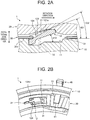
- the one end of the strut 12 is pushed by the elastic member 14 so as to be raised from the pocket plate 10 toward the notch plate 20 through the window hole 31 as shown in FIG. 2A and FIG. 2B .
- the notch plate 20 rotates in an engaging direction (the opposite direction from the "rotation direction” indicated in FIG. 1A ) relative to the pocket plate 10 with the one end of the strut 12 thus raised from the pocket plate 10 toward the notch plate 20, the strut 12 engages in the notch 21 and the SOWC 1 becomes engaged.
- the strut 12 engages in the notch 21, allowing a torque to be transmitted between the pocket plate 10 and the notch plate 20.
- the arm 40 transmits the driving force of an actuator (not shown), provided outside the SOWC 1, to the selector plate 30.
- a terminal end 41 of the arm 40 is inserted into a cutout 15 formed in an outer circumference of the pocket plate 10, and is coupled to the selector plate 30 inside the pocket plate 10.
- a leading end of the arm 40 exposed through the cutout 15 to the outside of the SOWC 1 is coupled to the actuator (not shown).
- the selector plate 30 is rotated through the arm 40.
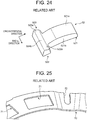
- the strut 52 of the related art includes a main body 521, an inner projection 522, and an outer projection 523.
- An upper surface 521a of the main body 521 has an even, gently curved shape.
- the main body 521 has a flat portion 524b that is provided between the inner projection 522 and the outer projection 523 so as to connect an upper surface 522a of the inner projection 522 and an upper surface 523a of the outer projection 523 to each other.
- the upper surface 522a of the inner projection 522, the upper surface 523a of the outer projection 523, and the flat portion 524b form one flat surface.
- the selector plate 70 of the related art has a plurality of rectangular window holes 71, and a cutout 72 through which the arm 40 (see FIG. 1B ) is coupled.
- the selector plate 70 accidentally rotates in a releasing direction as shown in FIG. 26 , for example, due to electrical failure of the actuator (not shown) that drives the arm 40, while the notch plate 20 is rotating at a high speed in the overrun direction, the strut 52 is raised toward the notch plate 20 by the spring force of the elastic member 14 as shown in FIG. 27 . Then, the strut 52 repeatedly hits the notch plate 20 rotating at a high speed and the pocket plate 10 by swinging up and down therebetween.
- a tensile stress due to the hitting concentrates around joint portions between the main body 521 (flat portion 524b) and the inner and outer projections 522, 523 that are portions with the lowest mechanical strength in the strut 52. This may shorten the life of the strut 52.
- the strut 52 accelerates beyond the restoring force of the elastic member 14 and is raised deep into the notch 21.
- the strut 52 is swung down by the notch plate 20 at a high speed, and a yaw moment My (see FIG. 22 ) and a translational force F1 (see FIG. 23 ) occur on the strut 52, causing one or both of the inner projection 522 and the outer projection 523 to hit an inner surface 11a of the pocket 11 at a high speed.
- Reasons why the yaw moment My and the translational force F1 occur on the strut 52 include, other than that the raised angle ⁇ 11 of the strut 52 is large, that, for manufacturing reasons, a clearance S between the inner surface 11a of the pocket 11 and a side surface 521b of the main body 521 of the strut 52 that determines the posture of the strut 52 is set to be large in the SOWC 101 of the related art as shown in FIG. 22 and FIG. 23 , and therefore the movement of the strut 52 in a yaw direction cannot be sufficiently blocked.
- the shapes of the strut 12 and the selector plate 30 are changed from those of the related art so as to suppress the phenomenon in which the strut 12 is swung down at a high speed by the notch plate 20 and the phenomenon in which the yaw moment My and the translational force F1 occur on the strut 12 as described above.
- the specific configurations of the strut 12 and the selector plate 30 of the SOWC 1 will be described with reference to FIG. 3 and FIG. 4 .
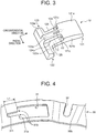
- the strut 12 includes a main body 121 extending along a circumferential direction of the pocket plate 10, and an inner projection 122 and an outer projection 123 extending along a radial direction of the SOWC 1 from an end of the main body 121 (an end thereof in the circumferential direction of the SOWC 1) from opposite sides of the main body.
- the inner projection 122 and the outer projection 123 constitute a rotational axis of the strut 12 when the strut 12 is raised.
- An upper surface 121a of the main body 121 has a gently curved shape.
- the main body 121 includes a protrusion 124 and inclined surfaces 125.
- the protrusion 124 is formed at the center of the upper surface 121a of the main body 121 in a width direction thereof, i.e., at the center of the upper surface 121a of the main body 121 in the radial direction of the SOWC 1, and is formed along the circumferential direction of the SOWC 1.
- the protrusion 124 is formed from a position of the center of the upper surface 121a of the main body 121 in a length direction thereof to the end of the main body 121. "This end of the main body 121" refers to the end of the main body 121 in an extension direction thereof, and the end from which the inner projection 122 and the outer projection 123 extend.
- An upper surface 124a of the protrusion 124 protrudes from the position of an upper surface 122a of the inner projection 122 and an upper surface 123a of the outer projection 123 in a plate thickness direction of the strut 12.
- the upper surface 124a of the protrusion 124 is provided at a higher level in the plate thickness direction of the strut 12 than the upper surface 122a of the inner projection 122 and the upper surface 123a of the outer projection 123.
- the upper surface 124a of the protrusion 124 serves as a contact portion that comes in contact with the notch plate 20 when the SOWC 1 is disengaged (the selector plate 30 is released) and the strut 12 is raised from the pocket plate 10 toward the notch plate 20 through the window hole 31.
- Side surfaces 124b of the protrusion 124 are formed so as to be parallel to side surfaces 121b of the main body 121.
- the protrusion 124 has a constant width when seen from above.
- the side surfaces 124b of the protrusion 124 and the side surfaces 121b of the main body 121 both have a flat shape in FIG. 3
- at least one of these side surfaces may have a curved shape with a predetermined radius of curvature. Therefore, the above description "that the side surfaces 124b of the protrusion 124 are parallel to the side surfaces 121b of the main body 121" includes not only a case where both side surfaces are perfectly parallel to each other but also a case where these are roughly (substantially) parallel to each other.
- the inclined surfaces 125 are formed respectively on both sides of the side surfaces 124b of the protrusion 124, and are inclined relative to the upper surface 122a of the inner projection 122 and the upper surface 123a of the outer projection 123.
- the inclined surfaces 125 and the protrusion 124 are located side by side in the radial direction of the SOWC 1
- the inner projection 122, the outer projection 123, and the protrusion 124 are located side by side in the radial direction of the SOWC 1.
- the selector plate 30 has the plurality of rectangular window holes 31, and the cutout 32 through which the arm 40 (see FIG. 1B ) is coupled.
- the selector plate 30 further has a cutout groove 311 that is formed so as to extend from an inner surface 31a of the window hole 31 along the formation direction of the protrusion 124, i.e., the circumferential direction of the SOWC 1.
- the cutout groove 311 is shaped so as to protrude from the window hole 31, and has a length roughly equal to the length of the protrusion 124 of the strut 12.
- the cutout groove 311 of the selector plate 30 moves so as to slide relative to the protrusion 124 of the strut 12, and the cutout groove 311 is fitted on the protrusion 124 as shown in FIG. 1A and FIG. 1B . Then, as shown in FIG. 1A , the strut 12 and the selector plate 30 overlap each other in a rotational axis direction of the SOWC 1.
- this state in which the strut 12 and the selector plate 30 overlap each other in the rotational axis direction of the SOWC 1 refers to a state in which at least the lower surface 30b of the selector plate 30 is located farther on a lower side in the rotational axis direction than the upper surface 121a of the main body 121 of the strut 12, and preferably a state in which the upper surface 121a of the main body 121 of the strut 12 and an upper surface 30a of the selector plate 30 are located at almost the same level, as shown in FIG. 1A .
- the distance between the strut 12 and the notch plate 20, i.e., a distance D12 between the upper surface 121a of the main body 121 of the strut 12 and a bottom surface of the notch 21 is smaller than a distance D11 (see FIG. 26 ) in the SOWC 101 of the related art.
- a raised angle ⁇ 12 of the strut 12 during an overrun is smaller than the raised angle ⁇ 11 (see FIG. 27 ) in the SOWC 101 of the related art.
- the swing-down speed of the strut 12 during an overrun is lower than that in the related art, and the force with which the strut 12 hits the notch plate 20 and the pocket plate 10 by swinging up and down therebetween is reduced.
- the raised angle ⁇ 12 of the strut 12 is limited as the cutout groove 311 of the selector plate 30 is fitted on the protrusion 124 provided at the center of the strut 12 in the width direction.
- part C indicated in FIG. 3 namely the upper surface 124a of the protrusion 124 comes in contact with the notch plate 20 during an overrun. Accordingly, when the strut 12 hits the notch plate 20, a downward force from the notch plate 20 acts on the strut 12, and a frictional force F2 from the notch plate 20 occurs on the upper surface 124a of the protrusion 124.
- the frictional force F2 acts on the protrusion 124 when the strut 12 hits the notch plate 20, and this frictional force F2 acts evenly in the width direction of the strut 12, so that a rolling movement of the strut 12 can be suppressed.
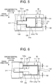
- a clearance S1 between the side surface 121b of the main body 121 of the strut 12 and the inner surface 31a of the window hole 31 of the selector plate 30 is preferably set to be smaller than a clearance S2 between the side surface 121b of the main body 121 of the strut 12 and the inner surface 11a of the pocket 11 in the SOWC1.
- the amount of movement of the strut 12 in the yaw direction can be reduced, and the movement of the strut 12 in the yaw direction can be sufficiently blocked. Accordingly, it is possible to further reduce the yaw moment My and the translational force F1, and to further reduce the force with which one or both of the inner projection 122 and the outer projection 123 of the strut 12 hits the inner surface 11a of the pocket 11.
- the strut 12 and the selector plate 30 overlap each other in the rotational axis direction of the SOWC 1 as shown in FIG. 1A . Since the position of the strut 12 and the movement thereof in the yaw direction inside the pocket 11 are restricted as the cutout groove 311 of the selector plate 30 is fitted on the protrusion 124 of the strut 12, the strut 12 is raised straight upward when the selector plate 30 is released. Thus, even when the clearance S1 between the strut 12 and the window hole 31 is set to be smaller than the clearance S2 between the strut 12 and the pocket 11, the strut 12 can be raised normally without getting caught on the window hole 31.
- the strut 52 and the selector plate 70 do not overlap each other in the rotational axis direction of the SOWC 101 as shown in FIG. 26 .
- the position of the strut 52 and the movement thereof in the yaw direction inside the pocket 11 are not restricted, so that the strut 52 may fail to rise straight upward when the selector plate 70 is released.
- the clearance between the strut 52 and the window hole 71 is set to be smaller than the clearance between the strut 52 and the pocket 11, the strut 52 may fail to rise normally by getting caught on the window hole 71.
- an angle ⁇ 22 of the inclined surface 125 relative to the lower surface 30b of the selector plate 30 when the strut 12 is raised from the pocket plate 10 toward the notch plate 20 through the window hole 31 during an overrun is preferably set to be larger than an angle ⁇ 21 of the upper surface 121a of the main body 121 of the strut 12 relative to the lower surface 30b of the selector plate 30, as shown in FIG. 2A .
- a driving angle ⁇ 32 of the arm 40 that actuates the selector plate 30 can be set to be smaller than a driving angle ⁇ 31 in the SOWC 101 of the related art. It is therefore possible to reduce the amount of stroke of the actuator (not shown) that actuates the arm 40 so as to rotate the selector plate 30, and thereby to downsize the actuator and achieve cost reduction.
- the force with which the strut 12 hits the notch plate 20 and the pocket plate 10 by swinging up and down therebetween during an overrun can be reduced, and the yaw moment My and the translational force F1 can be suppressed.
- the yaw moment My and the translational force F1 can be suppressed.
- the inner projection 122, the outer projection 123, and the protrusion 124 are disposed side by side in the radial direction of the SOWC 1, i.e., the protrusion 124 is provided so as to extend to the end of the main body 121.
- the protrusion 124 is provided so as to extend to the end of the main body 121.
- the SOWC according to this embodiment includes a strut 12A shown in FIG. 8 and a selector plate 30A shown in FIG. 9 , but the configuration of this SOWC is otherwise the same as that of the first embodiment.
- the strut 12A is obtained by extending the inclined surfaces 125 of the strut 12 of the first embodiment to the end of the main body 121.
- the strut 12A includes a main body 121A, the inner projection 122, and the outer projection 123.
- a protrusion 124A is provided on the upper surface 121a of the main body 121A along the circumferential direction of the SOWC.
- a pair of inclined surfaces 125A are provided respectively on both sides of the side surfaces 124b of the protrusion 124A.
- the protrusion 124A is formed at the center of the upper surface 121a of the main body 121A in the width direction.
- the protrusion 124A is formed from a position closer to the end of the main body 121A than the center of the upper surface 121a of the main body 121A in the length direction is, to the end of the main body 121A.
- the length of the protrusion 124A (the length thereof in the circumferential direction of the SOWC) is shorter than the length of the protrusion 124 of the strut 12 of the first embodiment.
- the inclined surface 125A is formed to a position at the end of the main body 121A. In the strut 12A thus configured, the inner projection 122, the outer projection 123, the inclined surfaces 125A, and the protrusion 124A are located side by side in the radial direction of the SOWC.
- the selector plate 30A has a plurality of rectangular window holes 31A and the cutout 32.
- the selector plate 30A further has a cutout groove 311A that is formed so as to extend from the inner surface 31a of the window hole 31A along the formation direction of the protrusion 124A of the strut 12A.
- a length L2 of the cutout groove 311A (the length thereof in the circumferential direction of the SOWC) is shorter than a length L1 of the cutout groove 311 (see FIG. 4 ) of the selector plate 30 of the first embodiment.
- the inner projection 122, the outer projection 123, the inclined surfaces 125A, and the protrusion 124A are disposed side by side in the radial direction of the SOWC.
- shortening the cutout groove 311A can reduce the amount of stroke of the actuator (not shown) that actuates the arm 40 (see FIG. 7 ) so as to rotate the selector plate 30A, which makes it possible to downsize the actuator and achieve cost reduction.
- the protrusion 124A is provided so as to extend to the end of the main body 121A as in the first embodiment.
- the mechanical strength around the joint portions between the main body 121A and the inner and outer projections 122, 123 can be enhanced.
- the inclined surfaces 125A are provided so as to extend to the end of the main body 121A.
- the thickness of the ends of the inclined surfaces 125A can be increased, and the rigidity and durability of the strut 12A can be thereby further enhanced.
- the SOWC 1B according to this embodiment includes a strut 12B shown in FIG. 10 , but the configuration of the SOWC 1B is otherwise the same as that of the second embodiment.
- the strut 12B is obtained by imparting a flat shape to a portion of each inclined surface 125A of the strut 12A of the second embodiment.
- the strut 12B includes a main body 121B, the inner projection 122, and the outer projection 123.
- a protrusion 124B is provided on the upper surface 121a of the main body 121B along the circumferential direction of the SOWC 1B.
- a pair of inclined surfaces 125B are provided respectively on both sides of the side surfaces 124b of the protrusion 124B.
- a flat contact portion 126B is provided at the position of the top of each inclined surface 125B, i.e., between the inclined surface 125B and the upper surface 121a of the main body 121B.
- the protrusion 124B is formed at the center of the upper surface 121a of the main body 121B in the width direction.
- the protrusion 124B is formed at the same position and with the same length as the protrusion 124A of the second embodiment.
- the flat contact portion 126B is provided at the position of the top of the inclined surface 125B. Specifically, as shown in FIG. 11 , the flat contact portion 126B is provided at a position within the inclined surface 125B at which the lower surface 30b of the selector plate 30A comes in contact when the selector plate 30A is closed (when the SOWC 1B is disengaged), i.e., at a position within the inclined surface 125B at which the lower surface 30b comes in contact when the selector plate 30A makes a full stroke.
- the flat contact portion 126B is formed so as to be parallel to the lower surface 30b of the selector plate 30A when the selector plate 30A is closed. In the strut 12B thus configured, as shown in FIG.
- the flat contact portions 126B and the protrusion 124B are located side by side in the radial direction of the SOWC 1B, and the inner projection 122, the outer projection 123, the inclined surfaces 125B, and the protrusion 124B are located side by side in the radial direction of the SOWC 1B.
- the SOWC 1B of the third embodiment as has been described above, when the selector plate 30A is closed and the strut 12B is housed inside the pocket 11, as shown in FIG. 11 , the lower surface 30b of the selector plate 30A and the flat contact portions 126B of the strut 12B come in surface contact with each other, so that the spring force of the elastic member 14 trying to raise the strut 12B acts nearly orthogonally to the lower surface 30b of the selector plate 30A.
- the external force mentioned above refers to a force that is exerted by the actuator (not shown) on the selector plate 30A through the arm 40 (see FIG. 7 ), and a force that keeps the selector plate 30A closed as shown in FIG. 11 .
- the SOWC 1B of this embodiment it is possible to reduce the driving force of the actuator (not shown), and thereby to downsize the actuator and achieve cost reduction.
- the protrusion 124B is provided so as to extend to the end of the main body 121B as in the first embodiment.
- the mechanical strength around the joint portions between the main body 121B and the inner and outer projections 122, 123 can be enhanced.
- the inclined surfaces 125B are provided so as to extend to the end of the main body 121B as in the second embodiment.
- the thickness of the ends of the inclined surfaces 125B can be increased, and the rigidity and durability of the strut 12B can be thereby further enhanced.
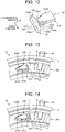
- the SOWC 1C according to this embodiment includes a strut 12C shown in FIG. 12 and a selector plate 30C shown in FIG. 13 , but the configuration of the SOWC 1C is otherwise the same as that of the first embodiment.
- the strut 12C is obtained by tapering the protrusion 124 of the strut 12 of the first embodiment.
- the strut 12C includes a main body 121C, the inner projection 122, and the outer projection 123.
- a protrusion 124C is provided on the upper surface 121a of the main body 121C along the circumferential direction of the SOWC 1C.
- a pair of inclined surfaces 125C are provided respectively on both sides of the side surfaces 124b of the protrusion 124C.
- the main body 121C includes a flat portion 127C that is provided between the inner projection 122 and the outer projection 123 so as to connect the upper surface 122a of the inner projection 122 and the upper surface 123a of the outer projection 123 to each other.
- the upper surface 122a of the inner projection 122, the upper surface 123a of the outer projection 123, and the flat portion 127C form one flat surface.
- the protrusion 124C has the side surfaces 124b that are inclined relative to the side surfaces 121b of the main body 121C, and the protrusion 124C is tapered toward the end of the main body 121C.
- the protrusion 124C has a V-shape when seen from above, and a bottom side of the V-shape has a linear shape.
- the side surfaces 124b of the protrusion 124C have a flat shape.
- the inclined surfaces 125C and the protrusion 124C are disposed side by side in the radial direction of the SOWC 1C, and the inner projection 122, the outer projection 123, and the flat portion 127C are disposed side by side in the radial direction of the SOWC 1C.
- the selector plate 30C has a plurality of window holes 31C as shown in FIG. 13 .
- the selector plate 30C further has a cutout groove 311C that is formed so as to extend from the inner surface 31a of the window hole 31C along the formation direction of the protrusion 124C of the strut 12C.
- the cutout groove 311C is tapered, and an inner surface of the cutout groove 311C has a flat shape.
- the tapered surfaces of the cutout groove 311C and the protrusion 124C come in contact with each other, which can reduce the bending stress occurring on the selector plate 30C when the selector plate 30C is closed.
- corners 121c are formed near an end of the protrusion 124 of the strut 12, and edges 31b (see FIG. 4 ) corresponding to the corners 121c are formed near an end of the cutout groove 311 of the selector plate 30. Accordingly, when the selector plate 30 is closed, the corners 121c of the strut 12 come in contact with the edges 31b of the selector plate 30, causing a bending stress on the edges 31b. In this embodiment, by contrast, the selector plate 30C does not have the edges 31b, so that the bending stress during contact with the strut 12C is reduced.
- the strut 12C and the selector plate 30C may be configured as shown in FIG. 14 .
- a protrusion 124D of a strut 12D is tapered like the strut 12C, but has a U-shape when seen from above.
- the side surfaces 124b of the protrusion 124D have a curved shape toward a leading end of the protrusion 124D.
- a cutout groove 311D of a window hole 31D of a selector plate 30D is tapered like the selector plate 30C, but has a U-shape when seen from above. Moreover, an inner surface of the cutout groove 311D has a curved shape toward a leading end of the cutout groove 311D.
- the tapered curved surfaces of the cutout groove 311D and the protrusion 124D come in contact with each other, which can further reduce the bending stress occurring on the selector plate 30D when the selector plate 30D is closed.
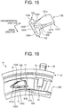
- the SOWC 1E according to a fifth embodiment will be described with reference to FIG. 15 and FIG. 16 .
- the SOWC 1E according to this embodiment includes a strut 12E shown in FIG. 15 and a selector plate 30E shown in FIG. 16 , but the configuration of the SOWC 1E is otherwise the same as that of the first embodiment.
- the strut 12E is obtained by extending the protrusion 124C of the strut 12C of the fourth embodiment to the end of the main body 121C.
- the strut 12E includes a main body 121E, the inner projection 122, and the outer projection 123.
- a protrusion 124E is provided on the upper surface 121a of the main body 121E along the circumferential direction of the SOWC 1E.
- a pair of inclined surfaces 125E are provided respectively on both sides of the side surfaces 124b of the protrusion 124E.
- the protrusion 124E has the side surfaces 124b that are inclined relative to the side surfaces 121b of the main body 121E, and the protrusion 124E is tapered toward the end of the main body 121E.
- the protrusion 124E has a V-shape when seen from above.
- the side surfaces 124b of the protrusion 124E have a flat shape.
- the inclined surfaces 125E and the protrusion 124E are located side by side in the radial direction of the SOWC 1E, and the inner projection 122, the outer projection 123, and the protrusion 124E are located side by side in the radial direction of the SOWC 1E.
- the selector plate 30E has a plurality of window holes 31E as shown in FIG. 16 .
- the selector plate 30E further has a cutout groove 311E that is formed so as to extend from the inner surface 31a of the window hole 31E along the formation direction of the protrusion 124E of the strut 12E.
- the cutout groove 311E is tapered, and an inner surface of the cutout groove 311E has a flat shape.
- the protrusion 124E is provided so as to extend to the end of the main body 121E as in the first embodiment.
- the mechanical strength around the joint portions between the main body 121E and the inner and outer projections 122, 123 can be enhanced.
- the bending stress occurring on the selector plate 30E when the selector plate 30E is closed can be reduced as in the fourth embodiment.
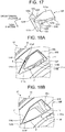
- the SOWC 1F according to this embodiment includes a strut 12F shown in FIG. 17 , but the configuration of the SOWC 1F is otherwise the same as that of the fifth embodiment.
- the strut 12F is obtained by curving the inclined surfaces 125E of the strut 12E of the fifth embodiment.
- the strut 12F includes a main body 121F, the inner projection 122, and the outer projection 123.
- a protrusion 124F is provided on the upper surface 121a of the main body 121F along the circumferential direction of the SOWC 1F.
- a pair of inclined surfaces 125F are provided respectively on both sides of the side surfaces 124b of the protrusion 124F.
- the configuration of the protrusion 124F is the same as the configuration of the protrusion 124E of the fifth embodiment, the description of the protrusion 124F will be omitted.
- the inclined surface 125F has a curved shape from the side surface 124b of the protrusion 124F to the side surface 121b of the main body 121F.
- the selector plate 30E switches from the released state to the closed state and the cutout groove 311E of the selector plate 30E is fitted on the protrusion 124E of the strut 12E, the lower surface 30b of the selector plate 30E and the inner surface 31a of the window hole 31E slide over the inclined surfaces 125E of the strut 12E while all the time remaining in point contact therewith as shown in parts D of FIG. 16 .
- the inclined surfaces 125F have a curved shape, so that, when the cutout groove 311E of the selector plate 30E is fitted on the protrusion 124F of the strut 12F, the lower surface 30b of the selector plate 30E and the inner surface 31a of the window hole 31E slide over the inclined surfaces 125F of the strut 12F while all the time remaining in line contact therewith as shown in parts E of FIG. 18A and parts F of FIG. 18B .
- the SOWC IF it is possible to reduce the contact pressure between the selector plate 30E and the strut 12F, and thereby to enhance the wear resistance of the selector plate 30E and the strut 12F.
- the protrusion 124F is provided so as to extend to an end of the main body 121F as in the first embodiment.
- the protrusion 124F is provided so as to extend to an end of the main body 121F as in the first embodiment.
- the bending stress occurring on the selector plate 30E when the selector plate 30E is closed can be reduced as in the fourth embodiment.
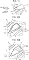
- the SOWC 1G according to this embodiment includes a strut 12G shown in FIG. 19 , but the configuration of the SOWC 1G is otherwise the same as that of the sixth embodiment.
- the strut 12G is obtained by extending the inclined surfaces 125F of the strut 12F of the sixth embodiment to the end of the main body 121F.
- the strut 12G includes a main body 121G, the inner projection 122, and the outer projection 123.
- a protrusion 124G is provided on the upper surface 121a of the main body 121G along the circumferential direction of the SOWC 1G.
- a pair of inclined surfaces 125G are provided respectively on both sides of the side surfaces 124b of the protrusion 124G.
- the configuration of the protrusion 124G is the same as the configuration of the protrusion 124E of the fifth embodiment, the description of the protrusion 124G will be omitted.
- the inclined surface 125G has a curved shape from the side surface 124b of the protrusion 124G to the side surface 121b of the main body 121G. Like the protrusion 124G, the inclined surfaces 125G are formed so as to extend to the end of the main body 121G. In the strut 12G thus configured, the inner projection 122, the outer projection 123, the inclined surfaces 125G, and the protrusion 124G are located side by side in the radial direction of the SOWC 1G.
- the length of a contact line between the selector plate 30E and the strut 12F is short at a stage where the selector plate 30E starts to close as shown in parts E of FIG. 18A .
- the curved inclined surfaces 125G are extended to the end of the main body 121G, so that, as shown in parts G of FIG. 20A , the length of a contact line between the selector plate 30E and the strut 12G at the stage where the selector plate 30E starts to close can be increased than that in the sixth embodiment.
- the inclined surfaces 125G are provided so as to extend to the end of the main body 121G as in the second embodiment.
- the protrusion 124G is provided so as to extend to the end of the main body 121G as in the first embodiment.
- the protrusion 124G is provided so as to extend to the end of the main body 121G as in the first embodiment.
- the bending stress occurring on the selector plate 30E when the selector plate 30E is closed can be reduced as in the fourth embodiment.
- the SOWC according to this embodiment includes a strut 12H shown in FIG. 21 , but the configuration of this SOWC is otherwise the same as that of the seventh embodiment.
- the strut 12H is obtained by imparting a flat shape to a portion of each inclined surface 125G of the strut 12G of the seventh embodiment.
- the strut 12H includes a main body 121H, the inner projection 122, and the outer projection 123.
- a protrusion 124H is provided on the upper surface 121a of the main body 121H along the circumferential direction of the SOWC.
- a pair of inclined surfaces 125H are provided respectively on both sides of the side surfaces 124b of the protrusion 124H.
- a flat contact portion 126H is provided at the position of the top of each inclined surface 125H, i.e., between the inclined surface 125H and the side surface 124b of the protrusion 124H.
- the configuration of the protrusion 124H is the same as the configuration of the protrusion 124G of the seventh embodiment, the description of the protrusion 124H will be omitted.
- the flat contact portion 126H is provided at a position within the inclined surface 125H at which the lower surface 30b of the selector plate 30E (see FIG. 20A ) comes in contact when the selector plate 30E is closed (when the SOWC is disengaged), i.e., a position within the inclined surface 125H at which the lower surface 30b comes in contact when the selector plate 30E makes a full stroke.
- the flat contact portion 126H is formed so as to be parallel to the lower surface 30b of the selector plate 30E when the selector plate 30E is closed.
- the lower surface 30b of the selector plate 30E (see FIG. 20A ) and the flat contact portions 126H of the strut 12H come in surface contact with each other as in the third embodiment.
- the protrusion 124H is provided so as to extend to the end of the main body 121H as in the first embodiment.
- the protrusion 124H is provided so as to extend to the end of the main body 121H as in the first embodiment.
- the inclined surfaces 125H are provided so as to extend to the end of the main body 121H as in the second embodiment.
- the bending stress occurring on the selector plate 30E (see FIG. 20A ) when the selector plate 30E is closed can be reduced as in the fourth embodiment.
- the curved inclined surfaces 125H are extended to the end of the main body 121H as in the sixth embodiment.
- the clearance between the side surface 121b of the main bodies 121A to 121H of the struts 12A to 12H and the inner surface 31a of the window holes 31A to 31E of the selector plates 30A to 30E is preferably set to be smaller than the clearance between the side surface 121b of the main bodies 121A to 121H of the struts 12A to 12H and the inner surface 11a of the pocket 11, as in the SOWC 1 according to the first embodiment.
- the angle of the inclined surfaces 125A to 125H relative to the lower surface 30b of the selector plates 30A to 30E when the struts 12A to 12H are raised from the pocket plate 10 toward the notch plate 20 through the window holes 31A to 31E during an overrun is preferably set to be larger than the angle of the upper surface 121a of the main bodies 121A to 121H of the struts 12A to 12H relative to the lower surface 30b of the selector plates 30A to 30E, as in the SOWC 1 according to the first embodiment.
- the flat contact portions 126B provided in the SOWC 1B according to the third embodiment may be provided in the SOWC 1 according to the first embodiment.
- the flat contact portion 126B can be provided at a position within the inclined surface 125 of the first embodiment at which the lower surface 30b of the selector plate 30 comes in contact when the selector plate 30 is closed (when the SOWC 1 is disengaged).
- the flat contact portions 126H provided in the SOWC according to the eighth embodiment may be provided in the SOWCs according to the fourth embodiment to the sixth embodiment.
- the flat contact portion 126H can be provided at a position within the inclined surfaces 125C to 125F of the fourth embodiment to the sixth embodiment at which the lower surface 30b of the selector plates 30C to 30E comes in contact when the selector plates 30C to 30E are closed (when the SOWCs are disengaged).
- the flat contact portions 126B provided in the SOWC 1B according to the third embodiment may be provided in the SOWCs according to the fourth embodiment to the eighth embodiment, or the flat contact portions 126H provided in the SOWC according to the eighth embodiment may be provided in the SOWCs according to the first embodiment to the third embodiment.
- the protrusions 124E to 124H have a V-shape when seen from above.
- the protrusions 124E to 124H may have a U-shape when seen from above, as in the SOWC 1D according to the modified example of the fourth embodiment.
- the protrusions 124 to 124B may be provided so as not to extend to the end of the main bodies 121 to 121B, and a flat portion that connects the upper surface 122a of the inner projection 122 and the upper surface 123a of the outer projection 123 to each other may be provided between the inner projection 122 and the outer projection 123 as in the SOWC 1C according to the fourth embodiment.
- the inclined surfaces 125 to 125B may have a curved shape like the inclined surfaces 125F of the SOWC 1F according to the sixth embodiment.
- the inclined surfaces 125E may be provided so as to extend to the end of the main body 121E like the inclined surfaces 125G of the SOWC 1G according to the seventh embodiment.
Landscapes
- Engineering & Computer Science (AREA)
- General Engineering & Computer Science (AREA)
- Mechanical Engineering (AREA)
- Chemical & Material Sciences (AREA)
- Gear-Shifting Mechanisms (AREA)
- Combustion & Propulsion (AREA)
- Vehicle Step Arrangements And Article Storage (AREA)
- Hydraulic Clutches, Magnetic Clutches, Fluid Clutches, And Fluid Joints (AREA)
- Transportation (AREA)
- Mechanical Operated Clutches (AREA)
- Details Of Garments (AREA)
- Hybrid Electric Vehicles (AREA)
- Casings For Electric Apparatus (AREA)
- Automation & Control Theory (AREA)
- Electrophotography Configuration And Component (AREA)
- Slide Fasteners, Snap Fasteners, And Hook Fasteners (AREA)
Abstract
Description
- The present invention relates to a selectable one-way clutch.
-
US Patent No. 8844693 discloses a selectable one-way clutch that includes a pocket plate having a plurality of pockets (housing recesses) in which struts (engaging tabs) are respectively housed, a notch plate having a plurality of notches (engaging recesses) in which the struts are respectively engaged, and a selector plate located between the pocket plate and the notch plate. - In a hybrid electric vehicle (HV) equipped with a selectable one-way clutch as described above, for example, when the vehicle travels in an EV mode etc., an "overrun" may occur in which the notch plate rotates in a direction (hereinafter referred to as an "overrun direction") that is opposite from an engaging direction of the selectable one-way clutch, i.e., from a direction in which the struts mesh with the notches.
- During an overrun, the strut behaves so as to hit the pocket plate and the notch plate by swinging up and down therebetween. When this up-and-down hitting behavior escalates, for example, large yaw moment My and translational fore F1 occur on a
strut 52 as shown inFIG. 22 and FIG. 23 . As a result, a pair of projections (inner projection 522 and outer projection 523) of thestrut 52 repeatedly hit aninner surface 11a of apocket 11 of apocket plate 10 as shown in parts A ofFIG. 22 and parts B ofFIG. 23 , which may shorten the life of thestrut 52. - The present invention provides a selectable one-way clutch that can avoid shortening the life of the engaging tab and enhance the durability of the engaging tab.
- An aspect of the present invention is a selectable one-way clutch. This selectable one-way clutch includes a pocket plate, engaging tabs, a notch plate, and a selector plate. The pocket plate includes a side surface and the side surface has a plurality of housing recesses. The engaging tabs are respectively housed in the housing recesses. The notch plate is provided so as to be rotatable relative to the pocket plate, and has a plurality of engaging recesses in a surface facing the surface of the pocket plate on the one side. The selector plate is located between the pocket plate and the notch plate. The selector plate has a plurality of window holes extending therethrough in a plate thickness direction. The selector plate is configured to rotate around the same rotational axis as the notch plate so as to switch between a state in which the engaging tab is raised from the pocket plate toward the notch plate through the window hole and a state in which the engaging tab is housed in the housing recess. The engaging tab includes a protrusion provided at the center of the engaging tab in the radial direction of the selectable one-way clutch. The selector plate has a cutout groove provided so as to extend from the window hole along the formation direction of the protrusion. The cutout groove is fitted on the protrusion, and the engaging tab and the selector plate overlap each other in the rotational axis direction of the selectable one-way clutch when the selectable one-way clutch is disengaged.
- Thus, when the selectable one-way clutch is disengaged (when the selector plate is closed), the distance between the engaging tab and the notch plate in this selectable one-way clutch is smaller than the distance therebetween in the related art. Accordingly, the raised angle of the engaging tab during an overrun in this selectable one-way clutch is smaller than the raised angle in the related art. Therefore, according to this selectable one-way clutch, the speed at which the engaging tab swings down during an overrun is lower than that in the related art, and the force with which the engaging tab hits the notch plate and the pocket plate by swinging up and down therebetween is reduced.
- In the above selectable one-way clutch, the engaging tab may include a main body extending along the circumferential direction of the selectable one-way clutch, and a pair of projections extending from opposite sides of the main body along the radial direction from an end of the main body in the circumferential direction, and constituting a rotational axis of the engaging tab when the engaging tab is raised. The main body may include the protrusion protruding from the position of an upper surface of the pair of projections. An upper surface of the protrusion may come in contact with the notch plate when the engaging tab is raised from the pocket plate toward the notch plate through the window hole.
- Thus, in this selectable one-way clutch, the speed at which the engaging tab swings down during an overrun is lower than that in the related art, and the force with which the engaging tab hits the notch plate and the pocket plate by swinging up and down therebetween is reduced.
- In the above selectable one-way clutch, the protrusion may have side surfaces parallel to side surfaces of the main body, and may extend to the end of the main body on the side of the pair of projections, and the engaging tab may include inclined surfaces provided respectively on both sides of the side surfaces of the protrusion and inclined relative to the upper surface of the pair of projections.
- Thus, in this selectable one-way clutch, the protrusion is provided so as to extend to the end of the main body, which can enhance the mechanical strength around joint portions between the main body and the pair of projections.
- In the above selectable one-way clutch, the protrusion may have side surfaces inclined relative to side surfaces of the main body, and may be tapered toward the end of the main body on the side of the pair of projections, and the engaging tab may include inclined surfaces provided respectively on both sides of the side surfaces of the protrusion and inclined relative to the upper surface of the pair of projections.
- Thus, in this selectable one-way clutch, the protrusion has a tapered shape, so that, when the cutout groove of the selector plate is fitted on the protrusion of the engaging tab, the tapered surfaces of the cutout groove and the protrusion come in contact with each other, which can reduce a bending stress occurring on the selector plate when the selector plate is closed. Accordingly, it is possible to enhance the durability of the selector plate and the actuation responsiveness of the engaging tab.
- In the above selectable one-way clutch, the inclined surfaces and the protrusion may be located side by side in the radial direction, and the pair of projections and the protrusion may be located side by side in the radial direction.
- Thus, in this selectable one-way clutch, the pair of projections and the protrusion are disposed side by side in the radial direction of the selectable one-way clutch, which can enhance the mechanical strength around the joint portions between the main body and the pair of projections.
- In the above selectable one-way clutch, the pair of projections, the inclined surfaces, and the protrusion may be located side by side in the radial direction.
- Thus, in this selectable one-way clutch, the pair of projections, the inclined surfaces, and the protrusion are disposed side by side in the radial direction of the selectable one-way clutch. Accordingly, it is possible to shorten the cutout groove of the selector plate, and thereby to enhance the rigidity and durability around the cutout groove of the selector plate.
- In the above selectable one-way clutch, the inclined surface may have a curved shape from the side surface of the protrusion to the side surface of the main body.
- Thus, in this selectable one-way clutch, the inclined surface has a curved shape, so that, when the cutout groove of the selector plate is fitted on the protrusion, a lower surface of the selector plate and an inner surface of the window hole slide over the inclined surfaces of the engaging tab while all the time remaining in line contact therewith. Accordingly, it is possible to reduce the contact pressure between the selector plate and the engaging tab, and thereby to enhance the wear resistance of the selector plate and the engaging tab.
- In the above selectable one-way clutch, the inclined surface may include a flat contact portion parallel to a lower surface of the selector plate. The flat contact portion may be provided at a position within the inclined surface at which the lower surface of the selector plate comes in contact when the selectable one-way clutch is disengaged.
- Thus, in this selectable one-way clutch, when the selector plate is closed and the engaging tab is housed inside the housing recess, the lower surface of the selector plate and the flat contact portion of the engaging tab come in surface contact with each other, which allows a spring force trying to raise the engaging tab to be resisted without requiring an external force. Accordingly, it is possible to reduce the driving force of an actuator that rotates the selector plate, and thereby to downsize the actuator and achieve cost reduction.
- In the above selectable one-way clutch, in the state in which the engaging tab is raised from the pocket plate toward the notch plate through the window hole, the angle of the inclined surface relative to a lower surface of the selector plate may be larger than the angle of an upper surface of the engaging tab relative to the lower surface of the selector plate.
- Thus, in this selectable one-way clutch, the driving angle of an arm that actuates the selector plate can be reduced. Accordingly, it is possible to reduce the driving force of the actuator that rotates the selector plate through the arm, and thereby to downsize the actuator and achieve cost reduction.
- In the above selectable one-way clutch, in the radial direction, a clearance between a side surface of the engaging tab and an inner surface of the window hole may be smaller than a clearance between the side surface of the engaging tab and a side surface of the housing recess.
- Thus, in this selectable one-way clutch, the amount of movement of the engaging tab in a yaw direction can be reduced, and the movement of the engaging tab in the yaw direction can be sufficiently blocked. Accordingly, it is possible to further reduce the yaw moment and the translational force, and thereby to further reduce the force with which one or both of the pair of projections of the engaging tab hit the inner surface of the housing recess.
- With the selectable one-way clutch of the present invention, the force with which the engaging tab hits the notch plate and the pocket plate by swinging up and down therebetween during an overrun can be reduced, and a yaw moment and a translational force can be suppressed. It is therefore possible to avoid shortening the life of the engaging tab and enhance the durability of the engaging tab.
- Features, advantages, and technical and industrial significance of exemplary embodiments of the invention will be described below with reference to the accompanying drawings, in which like numerals denote like elements, and wherein:
-
FIG. 1A is a view showing the configuration of a main part of a selectable one-way clutch according to a first embodiment of the present invention, and is a sectional view showing a disengaged state of the selectable one-way clutch; -
FIG. 1B is a view showing the configuration of the main part of the selectable one-way clutch according to the first embodiment of the present invention, and is a perspective view showing the disengaged state of the selectable one-way clutch; -
FIG. 2A is a view showing the configuration of the main part of the selectable one-way clutch according to the first embodiment of the present invention, and is a sectional view showing an engaged state of the selectable one-way clutch; -
FIG. 2B is a view showing the configuration of the main part of the selectable one-way clutch according to the first embodiment of the present invention, and is a perspective view showing the engaged state of the selectable one-way clutch; -
FIG. 3 is a perspective view showing the configuration of a strut of the selectable one-way clutch according to the first embodiment of the present invention; -
FIG. 4 is a perspective view showing the configuration of a selector plate of the selectable one-way clutch according to the first embodiment of the present invention; -
FIG. 5 is a plan view showing a relation between a clearance between a side surface of the strut and an inner surface of a window hole and a clearance between the side surface of the strut and a side surface of a pocket, during disengagement of the selectable one-way clutch according to the first embodiment of the present invention; -
FIG. 6 is a plan view showing a relation between the clearance between the side surface of the strut and the inner surface of the window hole and the clearance between the side surface of the strut and the side surface of the pocket, during engagement of the selectable one-way clutch according to the first embodiment of the present invention; -
FIG. 7 is a plan view illustrating a difference between an operation angle of the selector plate in the selectable one-way clutch according to the first embodiment of the present invention and that in the related art; -
FIG. 8 is a perspective view showing the configuration of a strut of a selectable one-way clutch according to a second embodiment of the present invention; -
FIG. 9 is a perspective view showing the configuration of a selector plate of the selectable one-way clutch according to the second embodiment of the present invention; -
FIG. 10 is a perspective view showing the configuration of a strut of a selectable one-way clutch according to a third embodiment of the present invention; -
FIG. 11 is a perspective view showing a disengaged state of the selectable one-way clutch according to the third embodiment of the present invention; -
FIG. 12 is a perspective view showing the configuration of a strut of a selectable one-way clutch according to a fourth embodiment of the present invention; -
FIG. 13 is a view showing the configuration of a main part of the selectable one-way clutch according to the fourth embodiment of the present invention, and is a perspective view showing an engaged state of the selectable one-way clutch; -
FIG. 14 is a view showing the configuration of a main part of a selectable one-way clutch according to a modified example of the fourth embodiment of the present invention, and is a perspective view showing an engaged state of the selectable one-way clutch; -
FIG. 15 is a perspective view showing the configuration of a strut of a selectable one-way clutch according to a fifth embodiment of the present invention; -
FIG. 16 is a view showing the configuration of a main part of the selectable one-way clutch according to the fifth embodiment of the present invention, and is a perspective view showing an engaged state of the selectable one-way clutch; -
FIG. 17 is a perspective view showing the configuration of a strut of a selectable one-way clutch according to a sixth embodiment of the present invention; -
FIG. 18A is a view showing the configuration of a main part of the selectable one-way clutch according to the sixth embodiment of the present invention, and is a perspective view showing an engaged state of the selectable one-way clutch; -
FIG. 18B is a view showing the configuration of the main part of the selectable one-way clutch according to the sixth embodiment of the present invention, and is a perspective view showing a disengaged state of the selectable one-way clutch; -
FIG. 19 is a perspective view showing the configuration of a strut of a selectable one-way clutch according to a seventh embodiment of the present invention; -
FIG. 20A is a view showing the configuration of a main part of the selectable one-way clutch according to the seventh embodiment of the present invention, and is a perspective view showing an engaged state of the selectable one-way clutch; -
FIG. 20B is a view showing the configuration of the main part of the selectable one-way clutch according to the seventh embodiment of the present invention, and is a perspective view showing a disengaged state of the selectable one-way clutch; -
FIG. 21 is a perspective view showing the configuration of a strut of a selectable one-way clutch according to an eighth embodiment of the present invention; -
FIG. 22 is a plan view illustrating a yaw moment occurring on a strut during an overrun in a selectable one-way clutch according to the related art; -
FIG. 23 is a plan view illustrating a translational force occurring on the strut during an overrun in the selectable one-way clutch according to the related art; -
FIG. 24 is a perspective view showing the configuration of the strut of the selectable one-way clutch according to the related art; -
FIG. 25 is a perspective view showing the configuration of a selector plate of the selectable one-way clutch according to the related art; -
FIG. 26 is a view showing the configuration of a main part of the selectable one-way clutch according to the related art, and is a sectional view showing a disengaged state of the selectable one-way clutch; and -
FIG. 27 is a view showing the configuration of the main part of the selectable one-way clutch according to the related art, and is a sectional view showing an engaged state of the selectable one-way clutch. - Selectable one-way clutches (hereinafter referred to as SOWCs) according to embodiments of the present invention will be described with reference to the drawings. However, the present invention is not limited to the following embodiments. Components in the following embodiments include those that can be easily substituted by those skilled in the art or that are substantially the same.
- An
SOWC 1 according to a first embodiment is installed in a power transmission device of a hybrid electric vehicle, for example, and includes apocket plate 10, anotch plate 20, aselector plate 30, and anarm 40 as shown inFIG. 1A and FIG. 1B. FIG. 1A is a sectional view showing theSOWC 1 as cut along the X-X direction indicated inFIG. 1B (at a position of aninner projection 122 of a strut 12 (seeFIG. 3 )).FIG. 1B is a perspective view showing theSOWC 1 with thenotch plate 20 removed. The "rotation direction" indicated inFIG. 1A refers to a direction in which thenotch plate 20 rotates during an overrun (an overrun direction; a disengaging direction of the SOWC 1). - The
pocket plate 10 has a cylindrical shape. A plurality of pockets (housing recesses) 11 recessed in a plate thickness direction of theSOWC 1 are formed in a surface of thepocket plate 10 on one side, i.e., in a surface facing thenotch plate 20, and plate-shaped struts (engaging tabs) 12 are respectively housed inside thepockets 11. - The
pockets 11 are formed at positions corresponding tonotches 21 of thenotch plate 20. Anelastic member 14 that urges thestrut 12 toward thenotch plate 20 is disposed between a recess 13 (seeFIG. 7 ) formed inside thepocket 11 and thestrut 12. When thepocket plate 10 is seen from the side of thenotch plate 20, theelastic member 14 is provided at the position of the center of thestrut 12 in a width direction thereof, and is actually not present in the section shown inFIG. 1A ; therefore, theelastic member 14 is indicated by dashed lines for the convenience of description (the same applies to the subsequent drawings). - As the
selector plate 30 rotates around the same rotational axis as thenotch plate 20, thestrut 12 switches between a state in which one end of thestrut 12 is raised from thepocket plate 10 toward thenotch plate 20 and a state in which theentire strut 12 including this one end is housed inside thepocket 11. As will be described later, thestrut 12 restricts rotation of thenotch plate 20 by engaging in thenotch 21 under a predetermined condition. - The
notch plate 20 has an annular (hollow disc) shape. Thenotch plate 20 is disposed so as to face the surface of thepocket plate 10 in which thepockets 11 are formed, and is configured to be rotatable relative to thepocket plate 10. - The plurality of notches (engaging recesses) 21 recessed in the plate thickness direction are formed in a surface of the
notch plate 20 facing thepocket plate 10. Thenotch 21 is a recess into which the one end of thestrut 12 raised from thepocket plate 10 toward thenotch plate 20 through awindow hole 31 of theselector plate 30 enters. - The
selector plate 30 has an annular (hollow disc), plate-like shape. Theselector plate 30 is located between thepocket plate 10 and thenotch plate 20. Theselector plate 30 switches between an engaged state and a disengaged state of theSOWC 1 as will be described later, by rotating a predetermined angle around the same rotational axis as thenotch plate 20. The window holes 31 that extend through theselector plate 30 in the plate thickness direction are formed at positions corresponding to thepockets 11 of thepocket plate 10 and thestruts 12. - Here, when the position of the
window hole 31 is shifted from the position of thepocket 11 in a circumferential direction of theSOWC 1, thestrut 12 is pushed toward thepocket 11 by alower surface 30b of theselector plate 30, so that thestrut 12 is housed inside thepocket 11 as shown inFIG. 1A and FIG. 1B . Thus, theSOWC 1 becomes disengaged. In this disengaged state, thestrut 12 does not engage in the notch 21 (engagement between thestrut 12 and thenotch 21 is dissolved), so that no torque is transmitted between thepocket plate 10 and thenotch plate 20. - On the other hand, when the position of the
window hole 31 roughly coincides with the position of thepocket 11 in the circumferential direction of theSOWC 1, the one end of thestrut 12 is pushed by theelastic member 14 so as to be raised from thepocket plate 10 toward thenotch plate 20 through thewindow hole 31 as shown inFIG. 2A and FIG. 2B . When thenotch plate 20 rotates in an engaging direction (the opposite direction from the "rotation direction" indicated inFIG. 1A ) relative to thepocket plate 10 with the one end of thestrut 12 thus raised from thepocket plate 10 toward thenotch plate 20, thestrut 12 engages in thenotch 21 and theSOWC 1 becomes engaged. In this engaged state, thestrut 12 engages in thenotch 21, allowing a torque to be transmitted between thepocket plate 10 and thenotch plate 20. - The
arm 40 transmits the driving force of an actuator (not shown), provided outside theSOWC 1, to theselector plate 30. Aterminal end 41 of thearm 40 is inserted into acutout 15 formed in an outer circumference of thepocket plate 10, and is coupled to theselector plate 30 inside thepocket plate 10. As shown inFIG. 1B , a leading end of thearm 40 exposed through thecutout 15 to the outside of theSOWC 1 is coupled to the actuator (not shown). As this actuator is driven, theselector plate 30 is rotated through thearm 40. - In the following, the specific configurations and actions of a
strut 52 and aselector plate 70 of anSOWC 101 of the related art will be described with reference toFIG. 22 to FIG. 27 . - As shown in
FIG. 24 , thestrut 52 of the related art includes amain body 521, aninner projection 522, and anouter projection 523. Anupper surface 521a of themain body 521 has an even, gently curved shape. Themain body 521 has aflat portion 524b that is provided between theinner projection 522 and theouter projection 523 so as to connect anupper surface 522a of theinner projection 522 and anupper surface 523a of theouter projection 523 to each other. Thus, in thestrut 52, theupper surface 522a of theinner projection 522, theupper surface 523a of theouter projection 523, and theflat portion 524b form one flat surface. - As shown in
FIG. 25 , theselector plate 70 of the related art has a plurality of rectangular window holes 71, and acutout 72 through which the arm 40 (seeFIG. 1B ) is coupled. - In the
SOWC 101 of the related art thus configured, if theselector plate 70 accidentally rotates in a releasing direction as shown inFIG. 26 , for example, due to electrical failure of the actuator (not shown) that drives thearm 40, while thenotch plate 20 is rotating at a high speed in the overrun direction, thestrut 52 is raised toward thenotch plate 20 by the spring force of theelastic member 14 as shown inFIG. 27 . Then, thestrut 52 repeatedly hits thenotch plate 20 rotating at a high speed and thepocket plate 10 by swinging up and down therebetween. As a result, a tensile stress due to the hitting concentrates around joint portions between the main body 521 (flat portion 524b) and the inner andouter projections strut 52. This may shorten the life of thestrut 52. - Here, as shown in
FIG. 26 and FIG. 27 , in the process in which thestrut 52 repeatedly hits thenotch plate 20 and thepocket plate 10 by swinging up and down therebetween, thestrut 52 accelerates beyond the restoring force of theelastic member 14 and is raised deep into thenotch 21. As a result, thestrut 52 is swung down by thenotch plate 20 at a high speed, and a yaw moment My (seeFIG. 22 ) and a translational force F1 (seeFIG. 23 ) occur on thestrut 52, causing one or both of theinner projection 522 and theouter projection 523 to hit aninner surface 11a of thepocket 11 at a high speed. - Reasons why the
strut 52 is swung down by thenotch plate 20 toward thepocket plate 10 at a high speed include that a raised angle θ11 of thestrut 52 is large in theSOWC 101 of the related art as shown inFIG. 27 , and accordingly the speed (hereinafter referred to as a "swing-down speed") at which thestrut 52 is swung down by thenotch plate 20 rotating at a high speed is high. - Reasons why the yaw moment My and the translational force F1 occur on the
strut 52 include, other than that the raised angle θ11 of thestrut 52 is large, that, for manufacturing reasons, a clearance S between theinner surface 11a of thepocket 11 and aside surface 521b of themain body 521 of thestrut 52 that determines the posture of thestrut 52 is set to be large in theSOWC 101 of the related art as shown inFIG. 22 and FIG. 23 , and therefore the movement of thestrut 52 in a yaw direction cannot be sufficiently blocked. - In view of the above, in the
SOWC 1 according to this embodiment, the shapes of thestrut 12 and theselector plate 30 are changed from those of the related art so as to suppress the phenomenon in which thestrut 12 is swung down at a high speed by thenotch plate 20 and the phenomenon in which the yaw moment My and the translational force F1 occur on thestrut 12 as described above. In the following, the specific configurations of thestrut 12 and theselector plate 30 of theSOWC 1 will be described with reference toFIG. 3 and FIG. 4 . - As shown in
FIG. 3 , thestrut 12 includes amain body 121 extending along a circumferential direction of thepocket plate 10, and aninner projection 122 and anouter projection 123 extending along a radial direction of theSOWC 1 from an end of the main body 121 (an end thereof in the circumferential direction of the SOWC 1) from opposite sides of the main body. Theinner projection 122 and theouter projection 123 constitute a rotational axis of thestrut 12 when thestrut 12 is raised. - An
upper surface 121a of themain body 121 has a gently curved shape. Themain body 121 includes aprotrusion 124 andinclined surfaces 125. Theprotrusion 124 is formed at the center of theupper surface 121a of themain body 121 in a width direction thereof, i.e., at the center of theupper surface 121a of themain body 121 in the radial direction of theSOWC 1, and is formed along the circumferential direction of theSOWC 1. Theprotrusion 124 is formed from a position of the center of theupper surface 121a of themain body 121 in a length direction thereof to the end of themain body 121. "This end of themain body 121" refers to the end of themain body 121 in an extension direction thereof, and the end from which theinner projection 122 and theouter projection 123 extend. - An
upper surface 124a of theprotrusion 124 protrudes from the position of anupper surface 122a of theinner projection 122 and anupper surface 123a of theouter projection 123 in a plate thickness direction of thestrut 12. Thus, theupper surface 124a of theprotrusion 124 is provided at a higher level in the plate thickness direction of thestrut 12 than theupper surface 122a of theinner projection 122 and theupper surface 123a of theouter projection 123. - The
upper surface 124a of theprotrusion 124 serves as a contact portion that comes in contact with thenotch plate 20 when theSOWC 1 is disengaged (theselector plate 30 is released) and thestrut 12 is raised from thepocket plate 10 toward thenotch plate 20 through thewindow hole 31. Side surfaces 124b of theprotrusion 124 are formed so as to be parallel to side surfaces 121b of themain body 121. Thus, theprotrusion 124 has a constant width when seen from above. - While the side surfaces 124b of the
protrusion 124 and the side surfaces 121b of themain body 121 both have a flat shape inFIG. 3 , at least one of these side surfaces may have a curved shape with a predetermined radius of curvature. Therefore, the above description "that the side surfaces 124b of theprotrusion 124 are parallel to the side surfaces 121b of themain body 121" includes not only a case where both side surfaces are perfectly parallel to each other but also a case where these are roughly (substantially) parallel to each other. - The
inclined surfaces 125 are formed respectively on both sides of the side surfaces 124b of theprotrusion 124, and are inclined relative to theupper surface 122a of theinner projection 122 and theupper surface 123a of theouter projection 123. In thestrut 12 thus configured, theinclined surfaces 125 and theprotrusion 124 are located side by side in the radial direction of theSOWC 1, and theinner projection 122, theouter projection 123, and theprotrusion 124 are located side by side in the radial direction of theSOWC 1. - As shown in
FIG. 4 , theselector plate 30 has the plurality of rectangular window holes 31, and thecutout 32 through which the arm 40 (seeFIG. 1B ) is coupled. Theselector plate 30 further has acutout groove 311 that is formed so as to extend from aninner surface 31a of thewindow hole 31 along the formation direction of theprotrusion 124, i.e., the circumferential direction of theSOWC 1. Thecutout groove 311 is shaped so as to protrude from thewindow hole 31, and has a length roughly equal to the length of theprotrusion 124 of thestrut 12. - In the
SOWC 1 including thestrut 12 and theselector plate 30 with the shapes as described above, when theSOWC 1 is disengaged (when theselector plate 30 is closed), thecutout groove 311 of theselector plate 30 moves so as to slide relative to theprotrusion 124 of thestrut 12, and thecutout groove 311 is fitted on theprotrusion 124 as shown inFIG. 1A and FIG. 1B . Then, as shown inFIG. 1A , thestrut 12 and theselector plate 30 overlap each other in a rotational axis direction of theSOWC 1. Specifically, "this state in which thestrut 12 and theselector plate 30 overlap each other in the rotational axis direction of theSOWC 1" refers to a state in which at least thelower surface 30b of theselector plate 30 is located farther on a lower side in the rotational axis direction than theupper surface 121a of themain body 121 of thestrut 12, and preferably a state in which theupper surface 121a of themain body 121 of thestrut 12 and anupper surface 30a of theselector plate 30 are located at almost the same level, as shown inFIG. 1A . - Thus, as shown in
FIG. 1A , when theSOWC 1 is disengaged (when theselector plate 30 is closed), the distance between thestrut 12 and thenotch plate 20, i.e., a distance D12 between theupper surface 121a of themain body 121 of thestrut 12 and a bottom surface of thenotch 21 is smaller than a distance D11 (seeFIG. 26 ) in theSOWC 101 of the related art. Accordingly, as shown inFIG. 2A , a raised angle θ12 of thestrut 12 during an overrun is smaller than the raised angle θ11 (seeFIG. 27 ) in theSOWC 101 of the related art. Thus, according to theSOWC 1 of this embodiment, the swing-down speed of thestrut 12 during an overrun is lower than that in the related art, and the force with which thestrut 12 hits thenotch plate 20 and thepocket plate 10 by swinging up and down therebetween is reduced. - In the
SOWC 1, the raised angle θ12 of thestrut 12 is limited as thecutout groove 311 of theselector plate 30 is fitted on theprotrusion 124 provided at the center of thestrut 12 in the width direction. Thus, part C indicated inFIG. 3 , namely theupper surface 124a of theprotrusion 124 comes in contact with thenotch plate 20 during an overrun. Accordingly, when thestrut 12 hits thenotch plate 20, a downward force from thenotch plate 20 acts on thestrut 12, and a frictional force F2 from thenotch plate 20 occurs on theupper surface 124a of theprotrusion 124. Thus, in theSOWC 1 having theprotrusion 124, the frictional force F2 acts on theprotrusion 124 when thestrut 12 hits thenotch plate 20, and this frictional force F2 acts evenly in the width direction of thestrut 12, so that a rolling movement of thestrut 12 can be suppressed. - Here, as shown in
FIG. 5 and FIG. 6 , in the radial direction of theSOWC 1, a clearance S1 between theside surface 121b of themain body 121 of thestrut 12 and theinner surface 31a of thewindow hole 31 of theselector plate 30 is preferably set to be smaller than a clearance S2 between theside surface 121b of themain body 121 of thestrut 12 and theinner surface 11a of thepocket 11 in the SOWC1. - Thus, the amount of movement of the
strut 12 in the yaw direction can be reduced, and the movement of thestrut 12 in the yaw direction can be sufficiently blocked. Accordingly, it is possible to further reduce the yaw moment My and the translational force F1, and to further reduce the force with which one or both of theinner projection 122 and theouter projection 123 of thestrut 12 hits theinner surface 11a of thepocket 11. - Setting the clearance S1 and the clearance S2 to the relation (clearance S1 < clearance S2) as shown in
FIG. 5 and FIG. 6 is possible in the structure of theSOWC 1 according to this embodiment, while this is not possible in the structure of theSOWC 101 according to the related art. - For example, in the
SOWC 1 according to this embodiment, when theselector plate 30 is closed (when theSOWC 1 is disengaged), thestrut 12 and theselector plate 30 overlap each other in the rotational axis direction of theSOWC 1 as shown inFIG. 1A . Since the position of thestrut 12 and the movement thereof in the yaw direction inside thepocket 11 are restricted as thecutout groove 311 of theselector plate 30 is fitted on theprotrusion 124 of thestrut 12, thestrut 12 is raised straight upward when theselector plate 30 is released. Thus, even when the clearance S1 between thestrut 12 and thewindow hole 31 is set to be smaller than the clearance S2 between thestrut 12 and thepocket 11, thestrut 12 can be raised normally without getting caught on thewindow hole 31. - By contrast, in the
SOWC 101 according to the related art, when theselector plate 70 is closed (when theSOWC 101 is disengaged), thestrut 52 and theselector plate 70 do not overlap each other in the rotational axis direction of theSOWC 101 as shown inFIG. 26 . Moreover, the position of thestrut 52 and the movement thereof in the yaw direction inside thepocket 11 are not restricted, so that thestrut 52 may fail to rise straight upward when theselector plate 70 is released. Thus, if the clearance between thestrut 52 and thewindow hole 71 is set to be smaller than the clearance between thestrut 52 and thepocket 11, thestrut 52 may fail to rise normally by getting caught on thewindow hole 71. - Here, in the
SOWC 1, an angle θ22 of theinclined surface 125 relative to thelower surface 30b of theselector plate 30 when thestrut 12 is raised from thepocket plate 10 toward thenotch plate 20 through thewindow hole 31 during an overrun is preferably set to be larger than an angle θ21 of theupper surface 121a of themain body 121 of thestrut 12 relative to thelower surface 30b of theselector plate 30, as shown inFIG. 2A . - Thus, compared with the
SOWC 101 of the related art (seeFIG. 27 ) including thestrut 52 that does not have theinclined surfaces 125, the contact angle of thelower surface 30b of theselector plate 30 relative to the strut 12 (specifically, the inclined surfaces 125) when theselector plate 30 is closed is reduced, so that thestrut 12 can be housed in thepocket 11 by a shorter stroke than in the related art. Accordingly, as shown inFIG. 7 , a driving angle θ32 of thearm 40 that actuates theselector plate 30 can be set to be smaller than a driving angle θ31 in theSOWC 101 of the related art. It is therefore possible to reduce the amount of stroke of the actuator (not shown) that actuates thearm 40 so as to rotate theselector plate 30, and thereby to downsize the actuator and achieve cost reduction. - According to the
SOWC 1 of the first embodiment as has been described above, the force with which thestrut 12 hits thenotch plate 20 and thepocket plate 10 by swinging up and down therebetween during an overrun can be reduced, and the yaw moment My and the translational force F1 can be suppressed. Thus, it is possible to avoid shortening the life of thestrut 12 and enhance the durability of thestrut 12. - According to the
SOWC 1, theinner projection 122, theouter projection 123, and theprotrusion 124 are disposed side by side in the radial direction of theSOWC 1, i.e., theprotrusion 124 is provided so as to extend to the end of themain body 121. Thus, it is possible to enhance the mechanical strength around the joint portions between themain body 121 and the inner andouter projections - An SOWC according to a second embodiment will be described with reference to
FIG. 8 and FIG. 9 . The SOWC according to this embodiment includes astrut 12A shown inFIG. 8 and aselector plate 30A shown inFIG. 9 , but the configuration of this SOWC is otherwise the same as that of the first embodiment. - The
strut 12A is obtained by extending theinclined surfaces 125 of thestrut 12 of the first embodiment to the end of themain body 121. As shown inFIG. 8 , thestrut 12A includes amain body 121A, theinner projection 122, and theouter projection 123. Aprotrusion 124A is provided on theupper surface 121a of themain body 121A along the circumferential direction of the SOWC. A pair ofinclined surfaces 125A are provided respectively on both sides of the side surfaces 124b of theprotrusion 124A. - The
protrusion 124A is formed at the center of theupper surface 121a of themain body 121A in the width direction. Theprotrusion 124A is formed from a position closer to the end of themain body 121A than the center of theupper surface 121a of themain body 121A in the length direction is, to the end of themain body 121A. The length of theprotrusion 124A (the length thereof in the circumferential direction of the SOWC) is shorter than the length of theprotrusion 124 of thestrut 12 of the first embodiment. Like theprotrusion 124A, theinclined surface 125A is formed to a position at the end of themain body 121A. In thestrut 12A thus configured, theinner projection 122, theouter projection 123, theinclined surfaces 125A, and theprotrusion 124A are located side by side in the radial direction of the SOWC. - As shown in
FIG. 9 , theselector plate 30A has a plurality ofrectangular window holes 31A and thecutout 32. Theselector plate 30A further has acutout groove 311A that is formed so as to extend from theinner surface 31a of thewindow hole 31A along the formation direction of theprotrusion 124A of thestrut 12A. A length L2 of thecutout groove 311A (the length thereof in the circumferential direction of the SOWC) is shorter than a length L1 of the cutout groove 311 (seeFIG. 4 ) of theselector plate 30 of the first embodiment. - According to the SOWC of the second embodiment as has been described above, the
inner projection 122, theouter projection 123, theinclined surfaces 125A, and theprotrusion 124A are disposed side by side in the radial direction of the SOWC. Thus, it is possible to shorten thecutout groove 311A of theselector plate 30A, and thereby to enhance the rigidity and durability around thecutout groove 311A of theselector plate 30A. Moreover, shortening thecutout groove 311A can reduce the amount of stroke of the actuator (not shown) that actuates the arm 40 (seeFIG. 7 ) so as to rotate theselector plate 30A, which makes it possible to downsize the actuator and achieve cost reduction. - According to the SOWC of the second embodiment, the
protrusion 124A is provided so as to extend to the end of themain body 121A as in the first embodiment. Thus, the mechanical strength around the joint portions between themain body 121A and the inner andouter projections - According to the SOWC of the second embodiment, the
inclined surfaces 125A are provided so as to extend to the end of themain body 121A. Thus, compared with the first embodiment (seeFIG. 3 ) in which theinclined surfaces 125 do not extend to the end of themain body 121, the thickness of the ends of theinclined surfaces 125A can be increased, and the rigidity and durability of thestrut 12A can be thereby further enhanced. - An
SOWC 1B according to a third embodiment will be described with reference toFIG. 10 and FIG. 11 . TheSOWC 1B according to this embodiment includes astrut 12B shown inFIG. 10 , but the configuration of theSOWC 1B is otherwise the same as that of the second embodiment. - The
strut 12B is obtained by imparting a flat shape to a portion of eachinclined surface 125A of thestrut 12A of the second embodiment. As shown inFIG. 10 , thestrut 12B includes amain body 121B, theinner projection 122, and theouter projection 123. Aprotrusion 124B is provided on theupper surface 121a of themain body 121B along the circumferential direction of theSOWC 1B. A pair ofinclined surfaces 125B are provided respectively on both sides of the side surfaces 124b of theprotrusion 124B. Aflat contact portion 126B is provided at the position of the top of eachinclined surface 125B, i.e., between theinclined surface 125B and theupper surface 121a of themain body 121B. - The
protrusion 124B is formed at the center of theupper surface 121a of themain body 121B in the width direction. Theprotrusion 124B is formed at the same position and with the same length as theprotrusion 124A of the second embodiment. - The
flat contact portion 126B is provided at the position of the top of theinclined surface 125B. Specifically, as shown inFIG. 11 , theflat contact portion 126B is provided at a position within theinclined surface 125B at which thelower surface 30b of theselector plate 30A comes in contact when theselector plate 30A is closed (when theSOWC 1B is disengaged), i.e., at a position within theinclined surface 125B at which thelower surface 30b comes in contact when theselector plate 30A makes a full stroke. Theflat contact portion 126B is formed so as to be parallel to thelower surface 30b of theselector plate 30A when theselector plate 30A is closed. In thestrut 12B thus configured, as shown inFIG. 10 , theflat contact portions 126B and theprotrusion 124B are located side by side in the radial direction of theSOWC 1B, and theinner projection 122, theouter projection 123, theinclined surfaces 125B, and theprotrusion 124B are located side by side in the radial direction of theSOWC 1B. - According to the
SOWC 1B of the third embodiment as has been described above, when theselector plate 30A is closed and thestrut 12B is housed inside thepocket 11, as shown inFIG. 11 , thelower surface 30b of theselector plate 30A and theflat contact portions 126B of thestrut 12B come in surface contact with each other, so that the spring force of theelastic member 14 trying to raise thestrut 12B acts nearly orthogonally to thelower surface 30b of theselector plate 30A. Thus, it is possible to resist the spring force of theelastic member 14 without requiring an external force. - The external force mentioned above refers to a force that is exerted by the actuator (not shown) on the
selector plate 30A through the arm 40 (seeFIG. 7 ), and a force that keeps theselector plate 30A closed as shown inFIG. 11 . Thus, according to theSOWC 1B of this embodiment, it is possible to reduce the driving force of the actuator (not shown), and thereby to downsize the actuator and achieve cost reduction. - According to the
SOWC 1B of the third embodiment, theprotrusion 124B is provided so as to extend to the end of themain body 121B as in the first embodiment. Thus, the mechanical strength around the joint portions between themain body 121B and the inner andouter projections - According to the
SOWC 1B of the third embodiment, theinclined surfaces 125B are provided so as to extend to the end of themain body 121B as in the second embodiment. Thus, the thickness of the ends of theinclined surfaces 125B can be increased, and the rigidity and durability of thestrut 12B can be thereby further enhanced. - An
SOWC 1C according to a fourth embodiment will be described with reference toFIG. 12 and FIG. 13 . TheSOWC 1C according to this embodiment includes astrut 12C shown inFIG. 12 and aselector plate 30C shown inFIG. 13 , but the configuration of theSOWC 1C is otherwise the same as that of the first embodiment. - The
strut 12C is obtained by tapering theprotrusion 124 of thestrut 12 of the first embodiment. As shown inFIG. 12 , thestrut 12C includes amain body 121C, theinner projection 122, and theouter projection 123. Aprotrusion 124C is provided on theupper surface 121a of themain body 121C along the circumferential direction of theSOWC 1C. A pair ofinclined surfaces 125C are provided respectively on both sides of the side surfaces 124b of theprotrusion 124C. Themain body 121C includes aflat portion 127C that is provided between theinner projection 122 and theouter projection 123 so as to connect theupper surface 122a of theinner projection 122 and theupper surface 123a of theouter projection 123 to each other. Thus, in thestrut 12C, theupper surface 122a of theinner projection 122, theupper surface 123a of theouter projection 123, and theflat portion 127C form one flat surface. - The
protrusion 124C has the side surfaces 124b that are inclined relative to the side surfaces 121b of themain body 121C, and theprotrusion 124C is tapered toward the end of themain body 121C. Theprotrusion 124C has a V-shape when seen from above, and a bottom side of the V-shape has a linear shape. The side surfaces 124b of theprotrusion 124C have a flat shape. In thestrut 12C thus configured, theinclined surfaces 125C and theprotrusion 124C are disposed side by side in the radial direction of theSOWC 1C, and theinner projection 122, theouter projection 123, and theflat portion 127C are disposed side by side in the radial direction of theSOWC 1C. - While the side surfaces 124b of the
protrusion 124C and the side surfaces 121b of themain body 121C both have a flat shape inFIG. 12 , at least one of these side surfaces may have a curved shape with a predetermined radius of curvature. The above description "that the side surfaces 124b of theprotrusion 124C are inclined relative to the side surfaces 121b of themain body 121C" means a case where both side surfaces are inclined at a predetermined angle or larger, and does not include a case where these are roughly (substantially) parallel to each other. - The
selector plate 30C has a plurality ofwindow holes 31C as shown inFIG. 13 . Theselector plate 30C further has acutout groove 311C that is formed so as to extend from theinner surface 31a of thewindow hole 31C along the formation direction of theprotrusion 124C of thestrut 12C. Like theprotrusion 124C, thecutout groove 311C is tapered, and an inner surface of thecutout groove 311C has a flat shape. - According to the
SOWC 1C of the fourth embodiment as has been described above, when thecutout groove 311C of theselector plate 30C is fitted on theprotrusion 124C of thestrut 12C, the tapered surfaces of thecutout groove 311C and theprotrusion 124C come in contact with each other, which can reduce the bending stress occurring on theselector plate 30C when theselector plate 30C is closed. Thus, it is possible to enhance the durability of theselector plate 30C and the actuation responsiveness of thestrut 12C. - For example, in the first embodiment,
corners 121c (seeFIG. 3 ) are formed near an end of theprotrusion 124 of thestrut 12, andedges 31b (seeFIG. 4 ) corresponding to thecorners 121c are formed near an end of thecutout groove 311 of theselector plate 30. Accordingly, when theselector plate 30 is closed, thecorners 121c of thestrut 12 come in contact with theedges 31b of theselector plate 30, causing a bending stress on theedges 31b. In this embodiment, by contrast, theselector plate 30C does not have theedges 31b, so that the bending stress during contact with thestrut 12C is reduced. - Alternatively, in the
SOWC 1C according to the fourth embodiment, thestrut 12C and theselector plate 30C may be configured as shown inFIG. 14 . In a modified example shown inFIG. 14 , aprotrusion 124D of astrut 12D is tapered like thestrut 12C, but has a U-shape when seen from above. Moreover, the side surfaces 124b of theprotrusion 124D have a curved shape toward a leading end of theprotrusion 124D. - A
cutout groove 311D of awindow hole 31D of aselector plate 30D is tapered like theselector plate 30C, but has a U-shape when seen from above. Moreover, an inner surface of thecutout groove 311D has a curved shape toward a leading end of thecutout groove 311D. - According to the
SOWC 1D of the modified example of the fourth embodiment as has been described above, when thecutout groove 311D of theselector plate 30D is fitted on theprotrusion 124D of thestrut 12D, the tapered curved surfaces of thecutout groove 311D and theprotrusion 124D come in contact with each other, which can further reduce the bending stress occurring on theselector plate 30D when theselector plate 30D is closed. Thus, it is possible to further enhance the durability of theselector plate 30D and the actuation responsiveness of thestrut 12D. - An
SOWC 1E according to a fifth embodiment will be described with reference toFIG. 15 and FIG. 16 . TheSOWC 1E according to this embodiment includes astrut 12E shown inFIG. 15 and aselector plate 30E shown inFIG. 16 , but the configuration of theSOWC 1E is otherwise the same as that of the first embodiment. - The
strut 12E is obtained by extending theprotrusion 124C of thestrut 12C of the fourth embodiment to the end of themain body 121C. As shown inFIG. 15 , thestrut 12E includes amain body 121E, theinner projection 122, and theouter projection 123. Aprotrusion 124E is provided on theupper surface 121a of themain body 121E along the circumferential direction of theSOWC 1E. A pair ofinclined surfaces 125E are provided respectively on both sides of the side surfaces 124b of theprotrusion 124E. - The
protrusion 124E has the side surfaces 124b that are inclined relative to the side surfaces 121b of themain body 121E, and theprotrusion 124E is tapered toward the end of themain body 121E. Theprotrusion 124E has a V-shape when seen from above. The side surfaces 124b of theprotrusion 124E have a flat shape. In thestrut 12E thus configured, theinclined surfaces 125E and theprotrusion 124E are located side by side in the radial direction of theSOWC 1E, and theinner projection 122, theouter projection 123, and theprotrusion 124E are located side by side in the radial direction of theSOWC 1E. - The
selector plate 30E has a plurality ofwindow holes 31E as shown inFIG. 16 . Theselector plate 30E further has acutout groove 311E that is formed so as to extend from theinner surface 31a of thewindow hole 31E along the formation direction of theprotrusion 124E of thestrut 12E. Like theprotrusion 124E, thecutout groove 311E is tapered, and an inner surface of thecutout groove 311E has a flat shape. - According to the
SOWC 1E of the fifth embodiment as has been described above, theprotrusion 124E is provided so as to extend to the end of themain body 121E as in the first embodiment. Thus, the mechanical strength around the joint portions between themain body 121E and the inner andouter projections - According to the
SOWC 1E, the bending stress occurring on theselector plate 30E when theselector plate 30E is closed can be reduced as in the fourth embodiment. Thus, it is possible to enhance the durability of theselector plate 30E and the actuation responsiveness of thestrut 12E. - An
SOWC 1F according to a sixth embodiment will be described with reference toFIG. 17 to FIG. 18B . TheSOWC 1F according to this embodiment includes astrut 12F shown inFIG. 17 , but the configuration of theSOWC 1F is otherwise the same as that of the fifth embodiment. - The
strut 12F is obtained by curving theinclined surfaces 125E of thestrut 12E of the fifth embodiment. As shown inFIG. 17 , thestrut 12F includes amain body 121F, theinner projection 122, and theouter projection 123. Aprotrusion 124F is provided on theupper surface 121a of themain body 121F along the circumferential direction of theSOWC 1F. A pair ofinclined surfaces 125F are provided respectively on both sides of the side surfaces 124b of theprotrusion 124F. As the configuration of theprotrusion 124F is the same as the configuration of theprotrusion 124E of the fifth embodiment, the description of theprotrusion 124F will be omitted. - The
inclined surface 125F has a curved shape from theside surface 124b of theprotrusion 124F to theside surface 121b of themain body 121F. - Here, for example, in the
SOWC 1E according to the fifth embodiment, when theselector plate 30E switches from the released state to the closed state and thecutout groove 311E of theselector plate 30E is fitted on theprotrusion 124E of thestrut 12E, thelower surface 30b of theselector plate 30E and theinner surface 31a of thewindow hole 31E slide over theinclined surfaces 125E of thestrut 12E while all the time remaining in point contact therewith as shown in parts D ofFIG. 16 . - By contrast, in the
SOWC 1F according to the sixth embodiment, theinclined surfaces 125F have a curved shape, so that, when thecutout groove 311E of theselector plate 30E is fitted on theprotrusion 124F of thestrut 12F, thelower surface 30b of theselector plate 30E and theinner surface 31a of thewindow hole 31E slide over theinclined surfaces 125F of thestrut 12F while all the time remaining in line contact therewith as shown in parts E ofFIG. 18A and parts F ofFIG. 18B . Thus, according to the SOWC IF, it is possible to reduce the contact pressure between theselector plate 30E and thestrut 12F, and thereby to enhance the wear resistance of theselector plate 30E and thestrut 12F. - According to the SOWC IF, the
protrusion 124F is provided so as to extend to an end of themain body 121F as in the first embodiment. Thus, it is possible to enhance the mechanical strength around the joint portions between themain body 121F and the inner andouter projections - According to the SOWC IF, the bending stress occurring on the
selector plate 30E when theselector plate 30E is closed can be reduced as in the fourth embodiment. Thus, it is possible to enhance the durability of theselector plate 30E and the actuation responsiveness of thestrut 12F. - An
SOWC 1G according to a seventh embodiment will be described with reference toFIG. 19 to FIG. 20B . TheSOWC 1G according to this embodiment includes astrut 12G shown inFIG. 19 , but the configuration of theSOWC 1G is otherwise the same as that of the sixth embodiment. - The
strut 12G is obtained by extending theinclined surfaces 125F of thestrut 12F of the sixth embodiment to the end of themain body 121F. As shown inFIG. 19 , thestrut 12G includes amain body 121G, theinner projection 122, and theouter projection 123. Aprotrusion 124G is provided on theupper surface 121a of themain body 121G along the circumferential direction of theSOWC 1G. A pair ofinclined surfaces 125G are provided respectively on both sides of the side surfaces 124b of theprotrusion 124G. As the configuration of theprotrusion 124G is the same as the configuration of theprotrusion 124E of the fifth embodiment, the description of theprotrusion 124G will be omitted. - The
inclined surface 125G has a curved shape from theside surface 124b of theprotrusion 124G to theside surface 121b of themain body 121G. Like theprotrusion 124G, theinclined surfaces 125G are formed so as to extend to the end of themain body 121G. In thestrut 12G thus configured, theinner projection 122, theouter projection 123, theinclined surfaces 125G, and theprotrusion 124G are located side by side in the radial direction of theSOWC 1G. - Here, for example, in the
SOWC 1F according to the sixth embodiment, the length of a contact line between theselector plate 30E and thestrut 12F is short at a stage where theselector plate 30E starts to close as shown in parts E ofFIG. 18A . - By contrast, in the
SOWC 1G according to the seventh embodiment, the curvedinclined surfaces 125G are extended to the end of themain body 121G, so that, as shown in parts G ofFIG. 20A , the length of a contact line between theselector plate 30E and thestrut 12G at the stage where theselector plate 30E starts to close can be increased than that in the sixth embodiment. Thus, according to theSOWC 1G, it is possible to further reduce the contact pressure between theselector plate 30E and thestrut 12G, and thereby to further enhance the wear resistance of theselector plate 30E and thestrut 12G. - According to the
SOWC 1G, theinclined surfaces 125G are provided so as to extend to the end of themain body 121G as in the second embodiment. Thus, it is possible to increase the thickness of the ends of theinclined surfaces 125G, and thereby to further enhance the rigidity and durability of thestrut 12G. - According to the
SOWC 1G, theprotrusion 124G is provided so as to extend to the end of themain body 121G as in the first embodiment. Thus, it is possible to enhance the mechanical strength around the joint portions between themain body 121G and the inner andouter projections - According to the
SOWC 1G, the bending stress occurring on theselector plate 30E when theselector plate 30E is closed can be reduced as in the fourth embodiment. Thus, it is possible to enhance the durability of theselector plate 30E and the actuation responsiveness of thestrut 12G. - An SOWC according to an eighth embodiment will be described with reference to
FIG. 21 . The SOWC according to this embodiment includes astrut 12H shown inFIG. 21 , but the configuration of this SOWC is otherwise the same as that of the seventh embodiment. - The
strut 12H is obtained by imparting a flat shape to a portion of eachinclined surface 125G of thestrut 12G of the seventh embodiment. As shown inFIG. 21 , thestrut 12H includes amain body 121H, theinner projection 122, and theouter projection 123. Aprotrusion 124H is provided on theupper surface 121a of themain body 121H along the circumferential direction of the SOWC. A pair ofinclined surfaces 125H are provided respectively on both sides of the side surfaces 124b of theprotrusion 124H. Aflat contact portion 126H is provided at the position of the top of eachinclined surface 125H, i.e., between theinclined surface 125H and theside surface 124b of theprotrusion 124H. As the configuration of theprotrusion 124H is the same as the configuration of theprotrusion 124G of the seventh embodiment, the description of theprotrusion 124H will be omitted. - Specifically, the
flat contact portion 126H is provided at a position within theinclined surface 125H at which thelower surface 30b of theselector plate 30E (seeFIG. 20A ) comes in contact when theselector plate 30E is closed (when the SOWC is disengaged), i.e., a position within theinclined surface 125H at which thelower surface 30b comes in contact when theselector plate 30E makes a full stroke. Theflat contact portion 126H is formed so as to be parallel to thelower surface 30b of theselector plate 30E when theselector plate 30E is closed. - According to the SOWC of the eighth embodiment as has been described above, the
lower surface 30b of theselector plate 30E (seeFIG. 20A ) and theflat contact portions 126H of thestrut 12H come in surface contact with each other as in the third embodiment. Thus, it is possible to resist the spring force of theelastic member 14 without requiring an external force. - According to the SOWC of the eighth embodiment, the
protrusion 124H is provided so as to extend to the end of themain body 121H as in the first embodiment. Thus, it is possible to enhance the mechanical strength around the joint portions between themain body 121H and the inner andouter projections - According to the SOWC of the eighth embodiment, the
inclined surfaces 125H are provided so as to extend to the end of themain body 121H as in the second embodiment. Thus, it is possible to increase the thickness of the ends of theinclined surfaces 125H, and thereby to further enhance the rigidity and durability of thestrut 12H. - According to the SOWC of the eighth embodiment, the bending stress occurring on the
selector plate 30E (seeFIG. 20A ) when theselector plate 30E is closed can be reduced as in the fourth embodiment. Thus, it is possible to enhance the durability of theselector plate 30E and the actuation responsiveness of thestrut 12H. - According to the SOWC of the eighth embodiment, the curved
inclined surfaces 125H are extended to the end of themain body 121H as in the sixth embodiment. Thus, it is possible to further reduce the contact pressure between theselector plate 30E (seeFIG. 20A ) and thestrut 12H, and thereby to further enhance the wear resistance of theselector plate 30E and thestrut 12H. - While the selectable one-way clutches according to the present invention have been specifically described based on the embodiments, the gist of the present invention is not limited to these embodiments but should be interpreted broadly based on the description of the claims. It is to be understood that the embodiments with various modifications and improvements made thereto based on the above description are included in the gist of the present invention.
- For example, in the SOWCs according to the second embodiment to the eighth embodiment, in the radial direction of the SOWCs, the clearance between the
side surface 121b of themain bodies 121A to 121H of thestruts 12A to 12H and theinner surface 31a of the window holes 31A to 31E of theselector plates 30A to 30E is preferably set to be smaller than the clearance between theside surface 121b of themain bodies 121A to 121H of thestruts 12A to 12H and theinner surface 11a of thepocket 11, as in theSOWC 1 according to the first embodiment. Thus, it is possible to further reduce the yaw moment My and the translational force F1 occurring on thestruts 12A to 12H, and to further reduce the force with which one or both of theinner projection 122 and theouter projection 123 of thestruts 12A to 12H hit theinner surface 11a of thepocket 11. - In the SOWCs according to the second embodiment to the eighth embodiment, the angle of the
inclined surfaces 125A to 125H relative to thelower surface 30b of theselector plates 30A to 30E when thestruts 12A to 12H are raised from thepocket plate 10 toward thenotch plate 20 through the window holes 31A to 31E during an overrun is preferably set to be larger than the angle of theupper surface 121a of themain bodies 121A to 121H of thestruts 12A to 12H relative to thelower surface 30b of theselector plates 30A to 30E, as in theSOWC 1 according to the first embodiment. Thus, it is possible to reduce the amount of stroke of the actuator (not shown) that actuates thearm 40, and thereby to downsize the actuator and achieve cost reduction. - The
flat contact portions 126B provided in theSOWC 1B according to the third embodiment may be provided in theSOWC 1 according to the first embodiment. In this case, theflat contact portion 126B can be provided at a position within theinclined surface 125 of the first embodiment at which thelower surface 30b of theselector plate 30 comes in contact when theselector plate 30 is closed (when theSOWC 1 is disengaged). - The
flat contact portions 126H provided in the SOWC according to the eighth embodiment may be provided in the SOWCs according to the fourth embodiment to the sixth embodiment. In this case, theflat contact portion 126H can be provided at a position within theinclined surfaces 125C to 125F of the fourth embodiment to the sixth embodiment at which thelower surface 30b of theselector plates 30C to 30E comes in contact when theselector plates 30C to 30E are closed (when the SOWCs are disengaged). - The
flat contact portions 126B provided in theSOWC 1B according to the third embodiment may be provided in the SOWCs according to the fourth embodiment to the eighth embodiment, or theflat contact portions 126H provided in the SOWC according to the eighth embodiment may be provided in the SOWCs according to the first embodiment to the third embodiment. - In the SOWCs according to the fifth embodiment to the eighth embodiment, the
protrusions 124E to 124H have a V-shape when seen from above. Alternatively, theprotrusions 124E to 124H may have a U-shape when seen from above, as in theSOWC 1D according to the modified example of the fourth embodiment. - In the SOWCs according to the first embodiment to the third embodiment, the
protrusions 124 to 124B may be provided so as not to extend to the end of themain bodies 121 to 121B, and a flat portion that connects theupper surface 122a of theinner projection 122 and theupper surface 123a of theouter projection 123 to each other may be provided between theinner projection 122 and theouter projection 123 as in theSOWC 1C according to the fourth embodiment. - In the SOWCs according to the first embodiment to the third embodiment, the
inclined surfaces 125 to 125B may have a curved shape like theinclined surfaces 125F of theSOWC 1F according to the sixth embodiment. - In the
SOWC 1E according to the fifth embodiment, theinclined surfaces 125E may be provided so as to extend to the end of themain body 121E like theinclined surfaces 125G of theSOWC 1G according to the seventh embodiment. - In the SOWCs according to the first embodiment to the eighth embodiment, the
upper surface 121a of themain bodies 121 to 121H has a gently curved shape, but theupper surface 121a may instead have a flat shape.
Claims (10)
- A selectable one-way clutch (1) comprising:a pocket plate (10) comprising a side surface, the side surface having a plurality of housing recesses (11);engaging tabs (12) respectively housed in the housing recesses (11);a notch plate (20) provided so as to be rotatable relative to the pocket plate (10), and having a plurality of engaging recesses (21) in a surface facing the surface of the pocket plate (10) on the one side; anda selector plate (30) located between the pocket plate (10) and the notch plate (20), the selector plate (30) having a plurality of window holes (31) extending therethrough in a plate thickness direction, the selector plate (30) being configured to rotate around the same rotational axis as the notch plate (20) so as to switch between a state in which the engaging tab (12) is raised from the pocket plate toward the notch plate through the window hole (31) and a state in which the engaging tab (12) is housed in the housing recess (11),the engaging tab (12) including a protrusion (124) provided at a center of the engaging tab (12) in a radial direction of the selectable one-way clutch (1),the selector plate (30) has a cutout groove (311) provided so as to extend from the window hole (31) along a formation direction of the protrusion (124), andthe cutout groove (311) is fitted on the protrusion (124) and the engaging tab (12) and the selector plate (30) overlap each other in a rotational axis direction of the selectable one-way clutch (1) when the selectable one-way clutch (1) is disengaged.
- The selectable one-way clutch (1) according to claim 1, wherein
the engaging tab (12) includes a main body (121) extending along a circumferential direction of the selectable one-way clutch (1), and a pair of projections (122, 123) extending from opposite sides of the main body along the radial direction from an end of the main body (121) in the circumferential direction, and constituting a rotational axis of the engaging tab (12) when the engaging tab (12) is raised,
the main body (121) includes the protrusion (124) protruding from a position of an upper surface of the pair of projections (122, 123), and
an upper surface of the protrusion (124) comes into contact with the notch plate (20) when the engaging tab (12) is raised from the pocket plate toward the notch plate through the window hole (31). - The selectable one-way clutch (1) according to claim 2, wherein
the protrusion (124) has side surfaces parallel to side surfaces of the main body (121), and extends to the end of the main body (121) on a side of the pair of projections, and
the engaging tab (12) includes inclined surfaces (125) provided respectively on both sides of the side surfaces of the protrusion (124) and inclined relative to the upper surface of the pair of projections (122, 123). - The selectable one-way clutch (1) according to claim 2, wherein
the protrusion (124) has side surfaces inclined relative to side surfaces of the main body (121), and is tapered toward the end of the main body (121) on a side of the pair of projections, and
the engaging tab (12) includes inclined surfaces (125) provided respectively on both sides of the side surfaces of the protrusion (124) and inclined relative to the upper surface of the pair of projections (122, 123). - The selectable one-way clutch (1) according to claim 3 or 4, wherein
the inclined surfaces (125) and the protrusion (124) are located side by side in the radial direction, and
the pair of projections (122, 123) and the protrusion (124) are located side by side in the radial direction. - The selectable one-way clutch (1) according to claim 3 or 4, wherein
the pair of projections (122, 123), the inclined surfaces (125), and the protrusion (124) are located side by side in the radial direction. - The selectable one-way clutch (1) according to any one of claims 3 to 6, wherein
the inclined surface (125) has a curved shape from the side surface of the protrusion (124) to the side surface of the main body (121). - The selectable one-way clutch (1) according to any one of claims 3 to 7, wherein
the inclined surface (125) includes a flat contact portion (126B) parallel to a lower surface of the selector plate (30), and
the flat contact portion (126B) is provided at a position within the inclined surface (125) at which the lower surface of the selector plate (30) comes in contact when the selectable one-way clutch (1) is disengaged. - The selectable one-way clutch (1) according to any one of claims 3 to 8, wherein,
in the state in which the engaging tab (12) is raised from the pocket plate toward the notch plate through the window hole (31), an angle of the inclined surface (125) relative to a lower surface of the selector plate (30) is larger than an angle of an upper surface of the engaging tab (12) relative to the lower surface of the selector plate (30). - The selectable one-way clutch (1) according to any one of claims 1 to 9, wherein,
in the radial direction, a clearance between a side surface of the engaging tab (12) and an inner surface of the window hole (31) is smaller than a clearance between the side surface of the engaging tab (12) and a side surface of the housing recess (11).
Applications Claiming Priority (1)
| Application Number | Priority Date | Filing Date | Title |
|---|---|---|---|
| JP2017052817A JP6614185B2 (en) | 2017-03-17 | 2017-03-17 | Selectable one-way clutch |
Publications (2)
| Publication Number | Publication Date |
|---|---|
| EP3388704A1 true EP3388704A1 (en) | 2018-10-17 |
| EP3388704B1 EP3388704B1 (en) | 2019-11-06 |
Family
ID=61655688
Family Applications (1)
| Application Number | Title | Priority Date | Filing Date |
|---|---|---|---|
| EP18161826.5A Active EP3388704B1 (en) | 2017-03-17 | 2018-03-14 | Selectable one-way clutch |
Country Status (13)
| Country | Link |
|---|---|
| US (1) | US10859128B2 (en) |
| EP (1) | EP3388704B1 (en) |
| JP (1) | JP6614185B2 (en) |
| KR (1) | KR102050008B1 (en) |
| CN (1) | CN108626267B (en) |
| AU (1) | AU2018201762B2 (en) |
| BR (1) | BR102018005155A2 (en) |
| CA (1) | CA2998165C (en) |
| MX (1) | MX383380B (en) |
| MY (1) | MY193122A (en) |
| PH (1) | PH12018050137B1 (en) |
| RU (1) | RU2678520C1 (en) |
| TW (1) | TWI664361B (en) |
Families Citing this family (9)
| Publication number | Priority date | Publication date | Assignee | Title |
|---|---|---|---|---|
| JP6493238B2 (en) * | 2016-02-02 | 2019-04-03 | トヨタ自動車株式会社 | Selectable one-way clutch |
| US10316904B2 (en) * | 2016-09-28 | 2019-06-11 | Means Industries, Inc. | Coupling assembly having an overrun mode and appendaged locking member for use therein |
| KR102173761B1 (en) * | 2018-12-14 | 2020-11-04 | 현대트랜시스 주식회사 | One way clutch reducing drag force by using magnetic force |
| US10982725B2 (en) | 2019-08-07 | 2021-04-20 | Schaeffler Technologies AG & Co. KG | Switchable ratcheting clutch |
| CN111120542A (en) * | 2020-01-15 | 2020-05-08 | 无锡明恒混合动力技术有限公司 | Mode-selectable clutch |
| US11739801B2 (en) * | 2020-06-02 | 2023-08-29 | Means Industries, Inc. | Coupling assembly and ratcheting locking member for use therein |
| US11719292B2 (en) | 2021-01-22 | 2023-08-08 | Means Industries, Inc. | Strut clutch assembly torque locking mechanism, and clutch strut |
| US11680610B2 (en) * | 2021-02-11 | 2023-06-20 | Means Industries, Inc. | Clutch assembly having normally on strut configured to prevent shock load deployment |
| JP7522332B1 (en) * | 2024-05-08 | 2024-07-24 | Nskワーナー株式会社 | Ratchet-type clutch device and vehicle drive device |
Citations (4)
| Publication number | Priority date | Publication date | Assignee | Title |
|---|---|---|---|---|
| US7258214B2 (en) * | 2005-06-09 | 2007-08-21 | Means Industries, Inc. | Overrunning coupling assembly and method for controlling the engagement of planar members |
| EP1944520A2 (en) * | 2007-01-12 | 2008-07-16 | GM Global Technology Operations, Inc. | Selectable one-way clutch with symmetrical struts |
| US8844693B2 (en) | 2011-09-13 | 2014-09-30 | Means Industries, Inc. | Coupling assembly having an overrun mode and ratcheting reverse strut or radial ratchet for use therein |
| JP2016166653A (en) * | 2015-03-10 | 2016-09-15 | トヨタ自動車株式会社 | Fixation structure of selectable one-way clutch |
Family Cites Families (15)
| Publication number | Priority date | Publication date | Assignee | Title |
|---|---|---|---|---|
| SU1032248A1 (en) * | 1982-01-29 | 1983-07-30 | Предприятие П/Я Г-4418 | Coupling |
| US5964331A (en) | 1996-12-02 | 1999-10-12 | Means Industries, Inc. | One-way overrunning clutch |
| JP3751470B2 (en) * | 1999-05-10 | 2006-03-01 | 株式会社ユニバンス | One-way clutch |
| JP2001090754A (en) * | 1999-09-20 | 2001-04-03 | Fuji Univance Corp | One-way clutch |
| US6615965B2 (en) | 2001-05-18 | 2003-09-09 | Epx, L.P. | Planar over-running clutch and method |
| JP5094660B2 (en) | 2008-09-19 | 2012-12-12 | 株式会社ユニバンス | Clutch device |
| US8602189B2 (en) * | 2010-03-05 | 2013-12-10 | Means Industries, Inc. | Diecast coupling member for use in an engageable coupling assembly |
| US8454466B2 (en) * | 2010-12-07 | 2013-06-04 | GM Global Technology Operations LLC | Hybrid powertrain system using selectable one-way clutches |
| US9121454B2 (en) * | 2012-10-12 | 2015-09-01 | Means Industries, Inc. | Overrunning coupling and control assembly, coupling assembly and locking member for use therein |
| JP6416116B2 (en) | 2013-01-10 | 2018-10-31 | ミーンズ インダストリーズ,インク. | Controllable or selectable coupling assembly with overrun mode and retained control element |
| JP6079762B2 (en) * | 2014-12-09 | 2017-02-15 | トヨタ自動車株式会社 | Selectable one-way clutch |
| US20160375754A1 (en) * | 2015-06-29 | 2016-12-29 | Toyota Jidosha Kabushiki Kaisha | Selectable one-way clutch and vehicle |
| JP6493106B2 (en) * | 2015-09-04 | 2019-04-03 | トヨタ自動車株式会社 | Selectable one-way clutch |
| US10145428B2 (en) * | 2016-02-04 | 2018-12-04 | Means Industries, Inc. | Coupling assembly having an overrun mode and channeled locking member for use therein |
| US10316904B2 (en) * | 2016-09-28 | 2019-06-11 | Means Industries, Inc. | Coupling assembly having an overrun mode and appendaged locking member for use therein |
-
2017
- 2017-03-17 JP JP2017052817A patent/JP6614185B2/en not_active Expired - Fee Related
-
2018
- 2018-03-12 AU AU2018201762A patent/AU2018201762B2/en not_active Ceased
- 2018-03-13 MY MYPI2018700996A patent/MY193122A/en unknown
- 2018-03-13 KR KR1020180029124A patent/KR102050008B1/en not_active Expired - Fee Related
- 2018-03-13 RU RU2018108840A patent/RU2678520C1/en active
- 2018-03-14 TW TW107108557A patent/TWI664361B/en not_active IP Right Cessation
- 2018-03-14 EP EP18161826.5A patent/EP3388704B1/en active Active
- 2018-03-15 US US15/922,162 patent/US10859128B2/en not_active Expired - Fee Related
- 2018-03-15 BR BR102018005155-5A patent/BR102018005155A2/en not_active IP Right Cessation
- 2018-03-15 CA CA2998165A patent/CA2998165C/en active Active
- 2018-03-15 CN CN201810211514.XA patent/CN108626267B/en not_active Expired - Fee Related
- 2018-03-15 PH PH12018050137A patent/PH12018050137B1/en unknown
- 2018-03-16 MX MX2018003393A patent/MX383380B/en unknown
Patent Citations (4)
| Publication number | Priority date | Publication date | Assignee | Title |
|---|---|---|---|---|
| US7258214B2 (en) * | 2005-06-09 | 2007-08-21 | Means Industries, Inc. | Overrunning coupling assembly and method for controlling the engagement of planar members |
| EP1944520A2 (en) * | 2007-01-12 | 2008-07-16 | GM Global Technology Operations, Inc. | Selectable one-way clutch with symmetrical struts |
| US8844693B2 (en) | 2011-09-13 | 2014-09-30 | Means Industries, Inc. | Coupling assembly having an overrun mode and ratcheting reverse strut or radial ratchet for use therein |
| JP2016166653A (en) * | 2015-03-10 | 2016-09-15 | トヨタ自動車株式会社 | Fixation structure of selectable one-way clutch |
Also Published As
| Publication number | Publication date |
|---|---|
| KR102050008B1 (en) | 2019-11-28 |
| RU2678520C1 (en) | 2019-01-29 |
| AU2018201762A1 (en) | 2018-10-04 |
| MX383380B (en) | 2025-03-13 |
| PH12018050137A1 (en) | 2019-05-15 |
| TWI664361B (en) | 2019-07-01 |
| CA2998165A1 (en) | 2018-09-17 |
| EP3388704B1 (en) | 2019-11-06 |
| MX2018003393A (en) | 2018-11-09 |
| US20180266503A1 (en) | 2018-09-20 |
| JP6614185B2 (en) | 2019-12-04 |
| TW201835466A (en) | 2018-10-01 |
| CN108626267B (en) | 2020-03-31 |
| AU2018201762B2 (en) | 2019-07-04 |
| US10859128B2 (en) | 2020-12-08 |
| PH12018050137B1 (en) | 2019-05-15 |
| KR20180106907A (en) | 2018-10-01 |
| CN108626267A (en) | 2018-10-09 |
| MY193122A (en) | 2022-09-26 |
| JP2018155329A (en) | 2018-10-04 |
| BR102018005155A2 (en) | 2018-12-18 |
| CA2998165C (en) | 2019-11-19 |
Similar Documents
| Publication | Publication Date | Title |
|---|---|---|
| EP3388704B1 (en) | Selectable one-way clutch | |
| ES2628001T3 (en) | Drive Member Selection | |
| EP1201962A1 (en) | Wear-elongation resistant silent chain | |
| US9683618B2 (en) | Selectable one-way clutch | |
| JP4838164B2 (en) | Power transmission device | |
| US20180038424A1 (en) | Pulley decoupler | |
| JP2013503282A (en) | Flywheel with starter gear | |
| US20170067517A1 (en) | Selectable one-way clutch | |
| US20090032786A1 (en) | Spare tire carrier having overload protection with controlled cable payout | |
| US20060169958A1 (en) | Spare tire carrier having overload protection with controlled cable payout | |
| JP6760471B2 (en) | Selectable one-way clutch | |
| US20040055851A1 (en) | Centrifugal clutch | |
| US9777794B2 (en) | Pendulum damping device for a motor vehicle torque transmission device | |
| JP2021025562A (en) | Coupling | |
| JP2019206976A5 (en) | ||
| JP2005273677A (en) | Power transmission device | |
| JP2017067238A (en) | Flexible flywheel device | |
| US20170146077A1 (en) | Selectable one-way clutch | |
| JP2012206610A (en) | Wiper arm | |
| JP2012206563A (en) | Wiper arm | |
| CN110657083A (en) | Driving disc for variable displacement compressor of automobile air conditioner | |
| KR20240159233A (en) | Connection structure of traction motor and double clutch | |
| KR101180664B1 (en) | Clip for Breakaway Prevention of Snap Ring | |
| JP2008069818A (en) | Rotation torque transmission | |
| JP2007170554A (en) | Power transmission device |
Legal Events
| Date | Code | Title | Description |
|---|---|---|---|
| PUAI | Public reference made under article 153(3) epc to a published international application that has entered the european phase |
Free format text: ORIGINAL CODE: 0009012 |
|
| STAA | Information on the status of an ep patent application or granted ep patent |
Free format text: STATUS: REQUEST FOR EXAMINATION WAS MADE |
|
| 17P | Request for examination filed |
Effective date: 20180413 |
|
| AK | Designated contracting states |
Kind code of ref document: A1 Designated state(s): AL AT BE BG CH CY CZ DE DK EE ES FI FR GB GR HR HU IE IS IT LI LT LU LV MC MK MT NL NO PL PT RO RS SE SI SK SM TR |
|
| AX | Request for extension of the european patent |
Extension state: BA ME |
|
| GRAP | Despatch of communication of intention to grant a patent |
Free format text: ORIGINAL CODE: EPIDOSNIGR1 |
|
| STAA | Information on the status of an ep patent application or granted ep patent |
Free format text: STATUS: GRANT OF PATENT IS INTENDED |
|
| RIC1 | Information provided on ipc code assigned before grant |
Ipc: F16D 41/14 20060101ALI20190509BHEP Ipc: F16D 41/12 20060101AFI20190509BHEP Ipc: F16D 41/16 20060101ALI20190509BHEP |
|
| INTG | Intention to grant announced |
Effective date: 20190604 |
|
| GRAS | Grant fee paid |
Free format text: ORIGINAL CODE: EPIDOSNIGR3 |
|
| GRAA | (expected) grant |
Free format text: ORIGINAL CODE: 0009210 |
|
| STAA | Information on the status of an ep patent application or granted ep patent |
Free format text: STATUS: THE PATENT HAS BEEN GRANTED |
|
| AK | Designated contracting states |
Kind code of ref document: B1 Designated state(s): AL AT BE BG CH CY CZ DE DK EE ES FI FR GB GR HR HU IE IS IT LI LT LU LV MC MK MT NL NO PL PT RO RS SE SI SK SM TR |
|
| REG | Reference to a national code |
Ref country code: GB Ref legal event code: FG4D |
|
| REG | Reference to a national code |
Ref country code: CH Ref legal event code: EP Ref country code: AT Ref legal event code: REF Ref document number: 1199112 Country of ref document: AT Kind code of ref document: T Effective date: 20191115 |
|
| REG | Reference to a national code |
Ref country code: DE Ref legal event code: R096 Ref document number: 602018001069 Country of ref document: DE |
|
| REG | Reference to a national code |
Ref country code: IE Ref legal event code: FG4D |
|
| REG | Reference to a national code |
Ref country code: NL Ref legal event code: MP Effective date: 20191106 |
|
| REG | Reference to a national code |
Ref country code: LT Ref legal event code: MG4D |
|
| PG25 | Lapsed in a contracting state [announced via postgrant information from national office to epo] |
Ref country code: FI Free format text: LAPSE BECAUSE OF FAILURE TO SUBMIT A TRANSLATION OF THE DESCRIPTION OR TO PAY THE FEE WITHIN THE PRESCRIBED TIME-LIMIT Effective date: 20191106 Ref country code: BG Free format text: LAPSE BECAUSE OF FAILURE TO SUBMIT A TRANSLATION OF THE DESCRIPTION OR TO PAY THE FEE WITHIN THE PRESCRIBED TIME-LIMIT Effective date: 20200206 Ref country code: GR Free format text: LAPSE BECAUSE OF FAILURE TO SUBMIT A TRANSLATION OF THE DESCRIPTION OR TO PAY THE FEE WITHIN THE PRESCRIBED TIME-LIMIT Effective date: 20200207 Ref country code: LT Free format text: LAPSE BECAUSE OF FAILURE TO SUBMIT A TRANSLATION OF THE DESCRIPTION OR TO PAY THE FEE WITHIN THE PRESCRIBED TIME-LIMIT Effective date: 20191106 Ref country code: PL Free format text: LAPSE BECAUSE OF FAILURE TO SUBMIT A TRANSLATION OF THE DESCRIPTION OR TO PAY THE FEE WITHIN THE PRESCRIBED TIME-LIMIT Effective date: 20191106 Ref country code: SE Free format text: LAPSE BECAUSE OF FAILURE TO SUBMIT A TRANSLATION OF THE DESCRIPTION OR TO PAY THE FEE WITHIN THE PRESCRIBED TIME-LIMIT Effective date: 20191106 Ref country code: PT Free format text: LAPSE BECAUSE OF FAILURE TO SUBMIT A TRANSLATION OF THE DESCRIPTION OR TO PAY THE FEE WITHIN THE PRESCRIBED TIME-LIMIT Effective date: 20200306 Ref country code: NO Free format text: LAPSE BECAUSE OF FAILURE TO SUBMIT A TRANSLATION OF THE DESCRIPTION OR TO PAY THE FEE WITHIN THE PRESCRIBED TIME-LIMIT Effective date: 20200206 Ref country code: LV Free format text: LAPSE BECAUSE OF FAILURE TO SUBMIT A TRANSLATION OF THE DESCRIPTION OR TO PAY THE FEE WITHIN THE PRESCRIBED TIME-LIMIT Effective date: 20191106 Ref country code: NL Free format text: LAPSE BECAUSE OF FAILURE TO SUBMIT A TRANSLATION OF THE DESCRIPTION OR TO PAY THE FEE WITHIN THE PRESCRIBED TIME-LIMIT Effective date: 20191106 |
|
| PG25 | Lapsed in a contracting state [announced via postgrant information from national office to epo] |
Ref country code: IS Free format text: LAPSE BECAUSE OF FAILURE TO SUBMIT A TRANSLATION OF THE DESCRIPTION OR TO PAY THE FEE WITHIN THE PRESCRIBED TIME-LIMIT Effective date: 20200306 Ref country code: RS Free format text: LAPSE BECAUSE OF FAILURE TO SUBMIT A TRANSLATION OF THE DESCRIPTION OR TO PAY THE FEE WITHIN THE PRESCRIBED TIME-LIMIT Effective date: 20191106 Ref country code: HR Free format text: LAPSE BECAUSE OF FAILURE TO SUBMIT A TRANSLATION OF THE DESCRIPTION OR TO PAY THE FEE WITHIN THE PRESCRIBED TIME-LIMIT Effective date: 20191106 |
|
| PG25 | Lapsed in a contracting state [announced via postgrant information from national office to epo] |
Ref country code: AL Free format text: LAPSE BECAUSE OF FAILURE TO SUBMIT A TRANSLATION OF THE DESCRIPTION OR TO PAY THE FEE WITHIN THE PRESCRIBED TIME-LIMIT Effective date: 20191106 |
|
| PG25 | Lapsed in a contracting state [announced via postgrant information from national office to epo] |
Ref country code: ES Free format text: LAPSE BECAUSE OF FAILURE TO SUBMIT A TRANSLATION OF THE DESCRIPTION OR TO PAY THE FEE WITHIN THE PRESCRIBED TIME-LIMIT Effective date: 20191106 Ref country code: EE Free format text: LAPSE BECAUSE OF FAILURE TO SUBMIT A TRANSLATION OF THE DESCRIPTION OR TO PAY THE FEE WITHIN THE PRESCRIBED TIME-LIMIT Effective date: 20191106 Ref country code: DK Free format text: LAPSE BECAUSE OF FAILURE TO SUBMIT A TRANSLATION OF THE DESCRIPTION OR TO PAY THE FEE WITHIN THE PRESCRIBED TIME-LIMIT Effective date: 20191106 Ref country code: CZ Free format text: LAPSE BECAUSE OF FAILURE TO SUBMIT A TRANSLATION OF THE DESCRIPTION OR TO PAY THE FEE WITHIN THE PRESCRIBED TIME-LIMIT Effective date: 20191106 Ref country code: RO Free format text: LAPSE BECAUSE OF FAILURE TO SUBMIT A TRANSLATION OF THE DESCRIPTION OR TO PAY THE FEE WITHIN THE PRESCRIBED TIME-LIMIT Effective date: 20191106 |
|
| REG | Reference to a national code |
Ref country code: DE Ref legal event code: R097 Ref document number: 602018001069 Country of ref document: DE |
|
| REG | Reference to a national code |
Ref country code: AT Ref legal event code: MK05 Ref document number: 1199112 Country of ref document: AT Kind code of ref document: T Effective date: 20191106 |
|
| PG25 | Lapsed in a contracting state [announced via postgrant information from national office to epo] |
Ref country code: SM Free format text: LAPSE BECAUSE OF FAILURE TO SUBMIT A TRANSLATION OF THE DESCRIPTION OR TO PAY THE FEE WITHIN THE PRESCRIBED TIME-LIMIT Effective date: 20191106 Ref country code: SK Free format text: LAPSE BECAUSE OF FAILURE TO SUBMIT A TRANSLATION OF THE DESCRIPTION OR TO PAY THE FEE WITHIN THE PRESCRIBED TIME-LIMIT Effective date: 20191106 |
|
| PLBE | No opposition filed within time limit |
Free format text: ORIGINAL CODE: 0009261 |
|
| STAA | Information on the status of an ep patent application or granted ep patent |
Free format text: STATUS: NO OPPOSITION FILED WITHIN TIME LIMIT |
|
| 26N | No opposition filed |
Effective date: 20200807 |
|
| PG25 | Lapsed in a contracting state [announced via postgrant information from national office to epo] |
Ref country code: MC Free format text: LAPSE BECAUSE OF FAILURE TO SUBMIT A TRANSLATION OF THE DESCRIPTION OR TO PAY THE FEE WITHIN THE PRESCRIBED TIME-LIMIT Effective date: 20191106 |
|
| PG25 | Lapsed in a contracting state [announced via postgrant information from national office to epo] |
Ref country code: AT Free format text: LAPSE BECAUSE OF FAILURE TO SUBMIT A TRANSLATION OF THE DESCRIPTION OR TO PAY THE FEE WITHIN THE PRESCRIBED TIME-LIMIT Effective date: 20191106 Ref country code: SI Free format text: LAPSE BECAUSE OF FAILURE TO SUBMIT A TRANSLATION OF THE DESCRIPTION OR TO PAY THE FEE WITHIN THE PRESCRIBED TIME-LIMIT Effective date: 20191106 |
|
| REG | Reference to a national code |
Ref country code: BE Ref legal event code: MM Effective date: 20200331 |
|
| PG25 | Lapsed in a contracting state [announced via postgrant information from national office to epo] |
Ref country code: LU Free format text: LAPSE BECAUSE OF NON-PAYMENT OF DUE FEES Effective date: 20200314 |
|
| PG25 | Lapsed in a contracting state [announced via postgrant information from national office to epo] |
Ref country code: IT Free format text: LAPSE BECAUSE OF FAILURE TO SUBMIT A TRANSLATION OF THE DESCRIPTION OR TO PAY THE FEE WITHIN THE PRESCRIBED TIME-LIMIT Effective date: 20191106 Ref country code: IE Free format text: LAPSE BECAUSE OF NON-PAYMENT OF DUE FEES Effective date: 20200314 |
|
| PG25 | Lapsed in a contracting state [announced via postgrant information from national office to epo] |
Ref country code: BE Free format text: LAPSE BECAUSE OF NON-PAYMENT OF DUE FEES Effective date: 20200331 |
|
| REG | Reference to a national code |
Ref country code: DE Ref legal event code: R084 Ref document number: 602018001069 Country of ref document: DE |
|
| REG | Reference to a national code |
Ref country code: GB Ref legal event code: 746 Effective date: 20210917 |
|
| REG | Reference to a national code |
Ref country code: CH Ref legal event code: PL |
|
| PG25 | Lapsed in a contracting state [announced via postgrant information from national office to epo] |
Ref country code: LI Free format text: LAPSE BECAUSE OF NON-PAYMENT OF DUE FEES Effective date: 20210331 Ref country code: CH Free format text: LAPSE BECAUSE OF NON-PAYMENT OF DUE FEES Effective date: 20210331 |
|
| PGFP | Annual fee paid to national office [announced via postgrant information from national office to epo] |
Ref country code: GB Payment date: 20220127 Year of fee payment: 5 Ref country code: DE Payment date: 20220203 Year of fee payment: 5 |
|
| PG25 | Lapsed in a contracting state [announced via postgrant information from national office to epo] |
Ref country code: TR Free format text: LAPSE BECAUSE OF FAILURE TO SUBMIT A TRANSLATION OF THE DESCRIPTION OR TO PAY THE FEE WITHIN THE PRESCRIBED TIME-LIMIT Effective date: 20191106 Ref country code: MT Free format text: LAPSE BECAUSE OF FAILURE TO SUBMIT A TRANSLATION OF THE DESCRIPTION OR TO PAY THE FEE WITHIN THE PRESCRIBED TIME-LIMIT Effective date: 20191106 Ref country code: CY Free format text: LAPSE BECAUSE OF FAILURE TO SUBMIT A TRANSLATION OF THE DESCRIPTION OR TO PAY THE FEE WITHIN THE PRESCRIBED TIME-LIMIT Effective date: 20191106 |
|
| PGFP | Annual fee paid to national office [announced via postgrant information from national office to epo] |
Ref country code: FR Payment date: 20220209 Year of fee payment: 5 |
|
| PG25 | Lapsed in a contracting state [announced via postgrant information from national office to epo] |
Ref country code: MK Free format text: LAPSE BECAUSE OF FAILURE TO SUBMIT A TRANSLATION OF THE DESCRIPTION OR TO PAY THE FEE WITHIN THE PRESCRIBED TIME-LIMIT Effective date: 20191106 |
|
| P01 | Opt-out of the competence of the unified patent court (upc) registered |
Effective date: 20230427 |
|
| REG | Reference to a national code |
Ref country code: DE Ref legal event code: R119 Ref document number: 602018001069 Country of ref document: DE |
|
| GBPC | Gb: european patent ceased through non-payment of renewal fee |
Effective date: 20230314 |
|
| PG25 | Lapsed in a contracting state [announced via postgrant information from national office to epo] |
Ref country code: GB Free format text: LAPSE BECAUSE OF NON-PAYMENT OF DUE FEES Effective date: 20230314 |
|
| PG25 | Lapsed in a contracting state [announced via postgrant information from national office to epo] |
Ref country code: GB Free format text: LAPSE BECAUSE OF NON-PAYMENT OF DUE FEES Effective date: 20230314 Ref country code: FR Free format text: LAPSE BECAUSE OF NON-PAYMENT OF DUE FEES Effective date: 20230331 Ref country code: DE Free format text: LAPSE BECAUSE OF NON-PAYMENT OF DUE FEES Effective date: 20231003 |