EP3388687A1 - Voltage application device, rotation apparatus and voltage application method - Google Patents
Voltage application device, rotation apparatus and voltage application method Download PDFInfo
- Publication number
- EP3388687A1 EP3388687A1 EP18173177.9A EP18173177A EP3388687A1 EP 3388687 A1 EP3388687 A1 EP 3388687A1 EP 18173177 A EP18173177 A EP 18173177A EP 3388687 A1 EP3388687 A1 EP 3388687A1
- Authority
- EP
- European Patent Office
- Prior art keywords
- voltage
- rotation
- disposed
- rotation shaft
- blades
- Prior art date
- Legal status (The legal status is an assumption and is not a legal conclusion. Google has not performed a legal analysis and makes no representation as to the accuracy of the status listed.)
- Granted
Links
- 238000000034 method Methods 0.000 title description 4
- 230000005484 gravity Effects 0.000 claims description 40
- 238000006243 chemical reaction Methods 0.000 claims description 33
- 230000005540 biological transmission Effects 0.000 abstract description 43
- 230000009466 transformation Effects 0.000 abstract description 8
- 238000010586 diagram Methods 0.000 description 25
- 230000009467 reduction Effects 0.000 description 12
- 230000006872 improvement Effects 0.000 description 9
- 238000007796 conventional method Methods 0.000 description 7
- 238000001228 spectrum Methods 0.000 description 6
- 238000010248 power generation Methods 0.000 description 5
- 238000002474 experimental method Methods 0.000 description 4
- 230000004888 barrier function Effects 0.000 description 3
- 230000000694 effects Effects 0.000 description 3
- 238000004519 manufacturing process Methods 0.000 description 2
- 230000002093 peripheral effect Effects 0.000 description 2
- 230000000717 retained effect Effects 0.000 description 2
- 238000000926 separation method Methods 0.000 description 2
- 239000000758 substrate Substances 0.000 description 2
- 230000001629 suppression Effects 0.000 description 2
- 238000012360 testing method Methods 0.000 description 2
- 238000009826 distribution Methods 0.000 description 1
- 238000010891 electric arc Methods 0.000 description 1
- 230000005669 field effect Effects 0.000 description 1
- 238000012986 modification Methods 0.000 description 1
- 230000004048 modification Effects 0.000 description 1
- 229920001721 polyimide Polymers 0.000 description 1
- 239000009719 polyimide resin Substances 0.000 description 1
- 238000003825 pressing Methods 0.000 description 1
- 230000000087 stabilizing effect Effects 0.000 description 1
- 238000006467 substitution reaction Methods 0.000 description 1
- 238000012795 verification Methods 0.000 description 1
Images


Classifications
-
- F—MECHANICAL ENGINEERING; LIGHTING; HEATING; WEAPONS; BLASTING
- F04—POSITIVE - DISPLACEMENT MACHINES FOR LIQUIDS; PUMPS FOR LIQUIDS OR ELASTIC FLUIDS
- F04D—NON-POSITIVE-DISPLACEMENT PUMPS
- F04D25/00—Pumping installations or systems
- F04D25/02—Units comprising pumps and their driving means
- F04D25/06—Units comprising pumps and their driving means the pump being electrically driven
-
- F—MECHANICAL ENGINEERING; LIGHTING; HEATING; WEAPONS; BLASTING
- F04—POSITIVE - DISPLACEMENT MACHINES FOR LIQUIDS; PUMPS FOR LIQUIDS OR ELASTIC FLUIDS
- F04D—NON-POSITIVE-DISPLACEMENT PUMPS
- F04D27/00—Control, e.g. regulation, of pumps, pumping installations or pumping systems specially adapted for elastic fluids
-
- F—MECHANICAL ENGINEERING; LIGHTING; HEATING; WEAPONS; BLASTING
- F01—MACHINES OR ENGINES IN GENERAL; ENGINE PLANTS IN GENERAL; STEAM ENGINES
- F01D—NON-POSITIVE DISPLACEMENT MACHINES OR ENGINES, e.g. STEAM TURBINES
- F01D5/00—Blades; Blade-carrying members; Heating, heat-insulating, cooling or antivibration means on the blades or the members
- F01D5/12—Blades
- F01D5/14—Form or construction
-
- F—MECHANICAL ENGINEERING; LIGHTING; HEATING; WEAPONS; BLASTING
- F03—MACHINES OR ENGINES FOR LIQUIDS; WIND, SPRING, OR WEIGHT MOTORS; PRODUCING MECHANICAL POWER OR A REACTIVE PROPULSIVE THRUST, NOT OTHERWISE PROVIDED FOR
- F03D—WIND MOTORS
- F03D7/00—Controlling wind motors
-
- F—MECHANICAL ENGINEERING; LIGHTING; HEATING; WEAPONS; BLASTING
- F03—MACHINES OR ENGINES FOR LIQUIDS; WIND, SPRING, OR WEIGHT MOTORS; PRODUCING MECHANICAL POWER OR A REACTIVE PROPULSIVE THRUST, NOT OTHERWISE PROVIDED FOR
- F03D—WIND MOTORS
- F03D7/00—Controlling wind motors
- F03D7/02—Controlling wind motors the wind motors having rotation axis substantially parallel to the air flow entering the rotor
- F03D7/022—Adjusting aerodynamic properties of the blades
-
- F—MECHANICAL ENGINEERING; LIGHTING; HEATING; WEAPONS; BLASTING
- F04—POSITIVE - DISPLACEMENT MACHINES FOR LIQUIDS; PUMPS FOR LIQUIDS OR ELASTIC FLUIDS
- F04D—NON-POSITIVE-DISPLACEMENT PUMPS
- F04D19/00—Axial-flow pumps
- F04D19/002—Axial flow fans
-
- F—MECHANICAL ENGINEERING; LIGHTING; HEATING; WEAPONS; BLASTING
- F04—POSITIVE - DISPLACEMENT MACHINES FOR LIQUIDS; PUMPS FOR LIQUIDS OR ELASTIC FLUIDS
- F04D—NON-POSITIVE-DISPLACEMENT PUMPS
- F04D29/00—Details, component parts, or accessories
- F04D29/26—Rotors specially for elastic fluids
- F04D29/32—Rotors specially for elastic fluids for axial flow pumps
- F04D29/321—Rotors specially for elastic fluids for axial flow pumps for axial flow compressors
- F04D29/324—Blades
-
- F—MECHANICAL ENGINEERING; LIGHTING; HEATING; WEAPONS; BLASTING
- F04—POSITIVE - DISPLACEMENT MACHINES FOR LIQUIDS; PUMPS FOR LIQUIDS OR ELASTIC FLUIDS
- F04D—NON-POSITIVE-DISPLACEMENT PUMPS
- F04D29/00—Details, component parts, or accessories
- F04D29/26—Rotors specially for elastic fluids
- F04D29/32—Rotors specially for elastic fluids for axial flow pumps
- F04D29/38—Blades
- F04D29/388—Blades characterised by construction
-
- F—MECHANICAL ENGINEERING; LIGHTING; HEATING; WEAPONS; BLASTING
- F04—POSITIVE - DISPLACEMENT MACHINES FOR LIQUIDS; PUMPS FOR LIQUIDS OR ELASTIC FLUIDS
- F04D—NON-POSITIVE-DISPLACEMENT PUMPS
- F04D29/00—Details, component parts, or accessories
- F04D29/66—Combating cavitation, whirls, noise, vibration or the like; Balancing
- F04D29/68—Combating cavitation, whirls, noise, vibration or the like; Balancing by influencing boundary layers
- F04D29/681—Combating cavitation, whirls, noise, vibration or the like; Balancing by influencing boundary layers especially adapted for elastic fluid pumps
- F04D29/687—Plasma actuators therefore
-
- G—PHYSICS
- G05—CONTROLLING; REGULATING
- G05D—SYSTEMS FOR CONTROLLING OR REGULATING NON-ELECTRIC VARIABLES
- G05D13/00—Control of linear speed; Control of angular speed; Control of acceleration or deceleration, e.g. of a prime mover
- G05D13/62—Control of linear speed; Control of angular speed; Control of acceleration or deceleration, e.g. of a prime mover characterised by the use of electric means, e.g. use of a tachometric dynamo, use of a transducer converting an electric value into a displacement
-
- H—ELECTRICITY
- H02—GENERATION; CONVERSION OR DISTRIBUTION OF ELECTRIC POWER
- H02M—APPARATUS FOR CONVERSION BETWEEN AC AND AC, BETWEEN AC AND DC, OR BETWEEN DC AND DC, AND FOR USE WITH MAINS OR SIMILAR POWER SUPPLY SYSTEMS; CONVERSION OF DC OR AC INPUT POWER INTO SURGE OUTPUT POWER; CONTROL OR REGULATION THEREOF
- H02M7/00—Conversion of ac power input into dc power output; Conversion of dc power input into ac power output
- H02M7/02—Conversion of ac power input into dc power output without possibility of reversal
-
- B—PERFORMING OPERATIONS; TRANSPORTING
- B64—AIRCRAFT; AVIATION; COSMONAUTICS
- B64C—AEROPLANES; HELICOPTERS
- B64C2230/00—Boundary layer controls
- B64C2230/12—Boundary layer controls by using electromagnetic tiles, fluid ionizers, static charges or plasma
-
- F—MECHANICAL ENGINEERING; LIGHTING; HEATING; WEAPONS; BLASTING
- F03—MACHINES OR ENGINES FOR LIQUIDS; WIND, SPRING, OR WEIGHT MOTORS; PRODUCING MECHANICAL POWER OR A REACTIVE PROPULSIVE THRUST, NOT OTHERWISE PROVIDED FOR
- F03D—WIND MOTORS
- F03D80/00—Details, components or accessories not provided for in groups F03D1/00 - F03D17/00
- F03D80/80—Arrangement of components within nacelles or towers
- F03D80/82—Arrangement of components within nacelles or towers of electrical components
- F03D80/85—Cabling
-
- F—MECHANICAL ENGINEERING; LIGHTING; HEATING; WEAPONS; BLASTING
- F05—INDEXING SCHEMES RELATING TO ENGINES OR PUMPS IN VARIOUS SUBCLASSES OF CLASSES F01-F04
- F05D—INDEXING SCHEME FOR ASPECTS RELATING TO NON-POSITIVE-DISPLACEMENT MACHINES OR ENGINES, GAS-TURBINES OR JET-PROPULSION PLANTS
- F05D2270/00—Control
- F05D2270/01—Purpose of the control system
- F05D2270/17—Purpose of the control system to control boundary layer
- F05D2270/172—Purpose of the control system to control boundary layer by a plasma generator, e.g. control of ignition
-
- Y—GENERAL TAGGING OF NEW TECHNOLOGICAL DEVELOPMENTS; GENERAL TAGGING OF CROSS-SECTIONAL TECHNOLOGIES SPANNING OVER SEVERAL SECTIONS OF THE IPC; TECHNICAL SUBJECTS COVERED BY FORMER USPC CROSS-REFERENCE ART COLLECTIONS [XRACs] AND DIGESTS
- Y02—TECHNOLOGIES OR APPLICATIONS FOR MITIGATION OR ADAPTATION AGAINST CLIMATE CHANGE
- Y02E—REDUCTION OF GREENHOUSE GAS [GHG] EMISSIONS, RELATED TO ENERGY GENERATION, TRANSMISSION OR DISTRIBUTION
- Y02E10/00—Energy generation through renewable energy sources
- Y02E10/70—Wind energy
- Y02E10/72—Wind turbines with rotation axis in wind direction
-
- Y—GENERAL TAGGING OF NEW TECHNOLOGICAL DEVELOPMENTS; GENERAL TAGGING OF CROSS-SECTIONAL TECHNOLOGIES SPANNING OVER SEVERAL SECTIONS OF THE IPC; TECHNICAL SUBJECTS COVERED BY FORMER USPC CROSS-REFERENCE ART COLLECTIONS [XRACs] AND DIGESTS
- Y02—TECHNOLOGIES OR APPLICATIONS FOR MITIGATION OR ADAPTATION AGAINST CLIMATE CHANGE
- Y02E—REDUCTION OF GREENHOUSE GAS [GHG] EMISSIONS, RELATED TO ENERGY GENERATION, TRANSMISSION OR DISTRIBUTION
- Y02E10/00—Energy generation through renewable energy sources
- Y02E10/70—Wind energy
- Y02E10/76—Power conversion electric or electronic aspects
-
- Y—GENERAL TAGGING OF NEW TECHNOLOGICAL DEVELOPMENTS; GENERAL TAGGING OF CROSS-SECTIONAL TECHNOLOGIES SPANNING OVER SEVERAL SECTIONS OF THE IPC; TECHNICAL SUBJECTS COVERED BY FORMER USPC CROSS-REFERENCE ART COLLECTIONS [XRACs] AND DIGESTS
- Y02—TECHNOLOGIES OR APPLICATIONS FOR MITIGATION OR ADAPTATION AGAINST CLIMATE CHANGE
- Y02T—CLIMATE CHANGE MITIGATION TECHNOLOGIES RELATED TO TRANSPORTATION
- Y02T50/00—Aeronautics or air transport
- Y02T50/10—Drag reduction
-
- Y—GENERAL TAGGING OF NEW TECHNOLOGICAL DEVELOPMENTS; GENERAL TAGGING OF CROSS-SECTIONAL TECHNOLOGIES SPANNING OVER SEVERAL SECTIONS OF THE IPC; TECHNICAL SUBJECTS COVERED BY FORMER USPC CROSS-REFERENCE ART COLLECTIONS [XRACs] AND DIGESTS
- Y02—TECHNOLOGIES OR APPLICATIONS FOR MITIGATION OR ADAPTATION AGAINST CLIMATE CHANGE
- Y02T—CLIMATE CHANGE MITIGATION TECHNOLOGIES RELATED TO TRANSPORTATION
- Y02T50/00—Aeronautics or air transport
- Y02T50/60—Efficient propulsion technologies, e.g. for aircraft
Definitions
- Embodiments described herein relate generally to a voltage application device, a rotation apparatus and a voltage application method.
- a voltage supply device such that an airflow generation device using plasma is disposed on the surface of a rotation blade included in a rotation apparatus such as a fan, a windmill or a turbine, and a voltage is supplied to a rotation field.
- This voltage application device applies a voltage between a first electrode of the airflow generation device provided on the surface of the blade which rotates and a second electrode disposed separately from the first electrode, to thereby generate airflow between the first electrode and the second electrode.
- a voltage application device of an embodiment applies a voltage between a first electrode and second electrode disposed separately from each other in an airflow generation device, which are disposed on a rotation blade of a rotation apparatus, in which a rotation shaft of the rotation blade is held rotatably by a holding part.
- a voltage output unit outputs a voltage.
- a sliding type transmission unit having electrodes disposed respectively on the rotation blade side and the holding part side of the rotation shaft transmits a voltage outputted from the voltage output unit from the holding part side to the rotation blade side.
- a transformation unit disposed on the rotation blade side increases the voltage transmitted by the sliding type transmission unit and outputs the voltage to the airflow generation device.
- FIG. 1 is a side view illustrating a structure of a voltage application device 30 according to one embodiment.
- this voltage application device 30 is disposed in a fan 10 which is a rotation apparatus.
- This fan 10 is a small fan for household use for example, and has a casing (case) 11, a bearing (holding part) 12 attached to the casing 11, a rotation shaft 13 supported rotatably by the bearing 12, and a plurality of blades (rotation blade) 14 attached to an end portion of the rotation shaft 13 and rotating together with the rotation shaft 13.
- an airflow generation device 20 generating plasma above the blades 14 is disposed, and a high-frequency high voltage is applied thereto by the voltage application device 30.
- FIG. 2 is a perspective view schematically illustrating the airflow generation device 20.
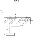
- FIG. 3 is a cross-sectional view illustrating an A-A cross section of FIG. 2 .
- the airflow generation device 20 has an electrode 22 (first electrode) exposed on a surface of a dielectric 21, and an electrode 23 (second electrode) which differs from the second electrode 22 in distance from the surface of the dielectric 21, is separated by shifting in a horizontal direction from the surface of the dielectric 21, and is embedded in the dielectric 21.
- a voltage application device 30 applying a voltage is connected via cables 24.
- the dielectric 21 and the pair of electrodes 22, 23 are disposed on the surface of the blade 14 to extend along a longitudinal direction (see FIG. 1 ).
- this airflow generation device 20 when a high-frequency high voltage is applied between the pair of electrodes 22, 23 by the voltage application device 30, discharge occurs between the pair of electrodes 22, 23, and discharge plasma occurs accompanying this discharge.
- dielectric barrier discharge since the dielectric 21 intervenes between the pair of electrodes 22, 23, there occurs dielectric barrier discharge, which does not reach arc discharge and is able to be maintained stably.
- This dielectric barrier discharge becomes creeping discharge formed along the dielectric 21.
- airflow 25 flowing in an arrow direction illustrated in FIG. 2 and FIG. 3 can be generated along the surface of the airflow generation device 20, that is, the surface of the dielectric 21.
- This generated airflow 25 enables airflow control effects such as flow separation suppression, suppression of noise and vibrations, and the like around the blade 14.
- FIG. 4 is a block diagram illustrating a structure of an electric circuit of the voltage application device 30.
- the voltage application device 30 includes an AC/DC conversion unit 31 converting an alternating voltage into a direct-current voltage, a high frequency generation unit 32 generating a high-frequency voltage, and a transformer 33 connected to the high frequency generation unit 32 via a sliding type transmission unit 35 (see FIG. 1 ) and generating a high-frequency high voltage.
- the AC/DC conversion unit 31 is disposed in the casing 11.
- the AC/DC conversion unit 31 converts, for example, a sinusoidal low voltage (AC) of a commercial frequency into a direct-current voltage (DC) via a not-illustrated diode and so on.
- the AC/DC conversion unit 31 functions as a voltage conversion unit converting an alternating voltage into a direct-current voltage. Note that regarding the alternating voltage, it is desired to use a triphase alternating voltage for suppressing ripples to be low.
- the high frequency generation unit 32 is disposed in the casing 11 as illustrated in FIG. 1 .
- the high frequency generation unit 32 is activated by a direct-current voltage supplied by, for example, switching using a IGBT (Insulated Gate Bipolar Transistor) or FET (Field-Effect Transistor) to generate high frequency pulses, and generate a high-frequency alternating voltage of about 1 [kHz] to 20 [kHz].
- the high frequency generation unit 32 is connected electrically to the sliding type transmission unit 35 via cables 34. This high frequency generation unit 32 has a function to generate a high-frequency component based on a direct-current voltage converted by the voltage conversion unit.
- the sliding type transmission unit (for example, slip ring) 35 has, as illustrated in FIG. 1 , two rings (electrodes) 35a attached to the rotation shaft 13 of the fan 10 and rotating with this rotation shaft 13, and two brushes (sliding contacts) 35b paired with the rings 35a and connected electrically to the high frequency generation unit 32.
- the two rings 35a are disposed on the blades 14 (rotation blade) side and the bearing 12 (holding part) sideon the rotation shaft 13, insulated electrically from each other, and both connected to the transformer 33.
- the ring 35a and the brush 35b are in electrical contact with each other, and have a function to transmit the high-frequency alternating voltage outputted from the high frequency generation unit 32 to the transformer 33. That is, the sliding type transmission unit 35 transmits the voltage from the side of the bearing 12 (holding part) to the side of the blades 14 (rotation blade).
- the brush may be disposed on the rotation shaft and the ring, which is in electrical contact with the brush, may be disposed on the holding part side.
- the transformer 33 is disposed on the rotation shaft 13 on the blades 14 side with respect to the rings 35a, as illustrated in FIG. 1 ,
- the transformer 33 increases the high-frequency alternating voltage of 100 [v] to 400 [v] for example transmitted from the rings 35a to a high-frequency high voltage of several [kV] and outputs the voltage to the airflow generation device 20.
- the transformer 33 is disposed on the rotation shaft 13 so that the center of gravity thereof substantially matches a center axis of the rotation shaft 13 of the fan 10.
- the transformer 33 has a function to convert the voltage outputted from the sliding type transmission unit 35 into a high-frequency high voltage and output the voltage to the airflow generation device 20.
- a distance L between the center axis of the rotation shaft 13 and the center of gravity 33a of the transformer 33 is equal to or smaller than 5% of a distance (hereinafter referred to as "blade length") L0 between the center axis of the rotation shaft 13 and the front end of the blades 14.
- the transformer 33 is disposed on, for example, the center axis of an end portion on the blades 14 side of the rotation shaft 13 so that the center of gravity thereof substantially matches the center axis of the rotation shaft 13, and the AC/DC conversion unit 31 and the high frequency generation unit 32 are disposed on the holding side (casing 11) of the fan 10.
- the high frequency generation unit 32 then generates a high-frequency alternating voltage based on the direct-current voltage generated in the AC/DC conversion unit 31, and this high-frequency alternating voltage can be supplied to the transformer 33 via the sliding type transmission unit 35.
- the transformer 33 converts the high-frequency alternating voltage transmitted from the sliding type transmission unit 35 into a high-frequency high voltage, and outputs it to the airflow generation device 20.
- the high-frequency high voltage can be applied to the airflow generation device 20 without applying a high voltage to the sliding type transmission unit 35 (rings 35a). Accordingly, the high-frequency high voltage can be supplied stably with low noise even while the rotation apparatus is operating (see experimental results which will be described later). As a result, operation of the airflow generation device becomes stable, and the airflow around the blades 14 is stabilized, thereby achieving reduction in noise and vibrations. Further, occurrence of noise due to discharge in sliding type contacts can be prevented, and wearing of contacts can be reduced.
- the transformer 33 having a large weight is disposed on the rotation shaft 13 so that its center of gravity substantially matches the center axis of the rotation shaft 13.
- moment applied to a supporting part of the transformer 33 and a rotation center can be suppressed small, and improvement in durability and reduction in vibrations and noise can be achieved.
- the transformer 33 is separate from the other parts of the voltage application device 30.
- the transformer 33 is disposed on the holding part (bearing 12) side, and then the other parts are disposed on the rotation blade (blades 14) side.
- an increase of weight of the rotation blade (blades 14) side can be suppressed least.
- the simplified structure of the bearing 12, a long life, a low cost, a lowering of moment applied to the rotation part, and simplification of designing can be achieved.
- the input to the voltage application device 30 is a direct-current voltage
- both the AC/DC conversion unit 31 and the DC/DC conversion unit may be omitted.
- FIG. 5 is a side view illustrating a structure of the voltage application device 30 of Embodiment 2.
- structures of the fan 10 and the airflow generation device 20 are similar to those in FIG. 1 , but an arrangement structure of the voltage application device 30 is different. Specifically, in this voltage application device 30, among the AC/DC conversion unit 31, the high frequency generation unit 32 and the transformer 33 which are necessary for driving the airflow generation device 20, the high frequency generation unit 32 and the transformer 33 are disposed on the rotation shaft 13 on the blades 14 side with respect to the rings 35a.
- the high frequency generation unit 32 and the transformer 33 are disposed on the rotation shaft 13 so that their combined center of gravity substantially matches the center axis of the rotation shaft 13 of the fan 10.
- the direct-current voltage generated in the AC/DC conversion unit 31 is outputted to the high frequency generation unit 32 via the sliding type transmission unit 35.
- this high frequency generation unit 32 has a filter function for obtaining a predetermined frequency band, but this filter function may be of a separate body.
- the filter function, the high frequency generation unit and the transformer are disposed on the rotation shaft 13 on the blades 14 side with respect to the rings 35a so that their combined center of gravity thereof substantially matches the center axis of the rotation shaft 13. Further, it is also possible to dispose only the filter function on the rotation shaft 13 on the blades 14 side, and to dispose the high frequency generation unit 32 on the holding side of the fan 10.
- the above-described substantially match refers to that, for example, a distance La between the center axis and the combined center of gravity of the high frequency generation unit 32 and the transformer 33 is equal to or smaller than 5% of the blade length L0.
- the high frequency generation unit 32 and the transformer 33 are disposed on this rotation shaft 13 so that their combined center of gravity substantially matches the center axis of the rotation shaft 13, and the direct-current voltage outputted from the AC/DC conversion unit 31 is supplied to the high frequency generation unit 32 via the sliding type transmission unit 35.
- the filter function of the high frequency generation unit 32 prevents the momentary variation of the direct-current voltage from being transmitted to the transformer 33, and the high-frequency high voltage can be supplied stably with low noise even while the rotation apparatus is operating. As a result, voltage supply to the airflow generation device 20 becomes stable, and stable plasma discharge can be maintained.
- the high frequency generation unit 32 and the transformer 33 are disposed on the rotation shaft 13 so that their combined center of gravity substantially matches the center axis of the rotation shaft 13.
- moment applied to the supporting part of the transformer 33 and the rotation center of the rotation shaft 13 can be suppressed small, and improvement in durability and reduction in vibrations and noise can be achieved.
- the AC/DC conversion unit 31 is disposed on the holding part (bearing 12) side.
- the AC/DC conversion unit 31 may be disposed on the rotation blade (blades 14) side, and then the sinusoidal low voltage (AC) of a commercial frequency may be supplied to the AC/DC conversion unit 31 via the sliding type transmission unit 35.
- AC sinusoidal low voltage
- FIG. 6 is a side view illustrating a structure of the voltage application device 30 of Embodiment 3.
- FIG. 7 is an enlarged cross-sectional view illustrating an attached state of the rotation shaft 13 and a slip ring (sliding type transmission unit) 35 of FIG. 6 .
- the structures of the fan 10 and the airflow generation device 20 are similar to those in FIG. 1 , but an arrangement structure of the voltage application device 30 is different. Specifically, in this voltage application device 30, rings 35a of the slip ring 35 are attached to an end portion 13a on a side opposite to the bearing 12 side of the rotation shaft 13, brushes 35b are in electrical contact with the rings 35a, and a direct-current voltage outputted from the AC/DC conversion unit 31 is supplied to the high frequency generation unit 32 via the sliding type transmission unit 35.
- the other end in the longitudinal direction of the attachment shaft 35c is inserted and fitted in the hole 13b of the end portion 13a of the rotation shaft 13, and further, the attachment shaft 35c can be fixed to the end portion 13a of the rotation shaft 13 using a screw 40.
- the attachment shaft 35c to which the rings 35a are fixed is fitted in the hole 13b of the end portion 13a of the rotation shaft 13.
- the radius of rotation of the rings 35a can be made small and a sliding distance per rotation can be made short, as compared to the case of FIG. 1 where the rings 35a are attached directly to the rotation shaft 13.
- the rotation shaft 13 needs to mechanically support the rotational structure of the fan 10, and hence is one having a round bar shape with a necessary thickness.
- the slip ring 35 is disposed thereon as in FIG. 1 , it is necessary to make the diameter of the rings 35a larger than the diameter of the round bar, and a sliding distance per rotation becomes large.
- FIG. 1 In the structure as illustrated in FIG.
- the round bar to which the slip ring 35 is attached becomes as denoted by 35c, and this round bar just needs to have strength for supporting only the rotational structure of the slip ring 35. Accordingly, a thin round bar can be used, and the diameter of the rings 35a to be attached thereto can also be made small, making the sliding distance per rotation short.
- the wearing ratio of the brushes 35b when the rotation shaft 13 is rotated at the same rotation speed can be reduced more than in the case of FIG. 1 , and the usable life of the sliding type transmission unit 35 can be improved.
- the high-frequency high voltage can be supplied stably with low noise even while the rotation apparatus is operating.
- the high frequency generation unit 32 and the transformer 33 are disposed on the rotation shaft 13 so that their combined center of gravity substantially matches the center axis of the rotation shaft 13.
- moment applied to the supporting part of the transformer 33 and the rotation center of the rotation shaft 13 can be suppressed small, and improvement in durability and reduction in vibrations and noise can be achieved.
- the above-described substantially match refers to that, for example, the distance La between the center axis and the combined center of gravity of the high frequency generation unit 32 and the transformer 33 is equal to or smaller than 5% of the blade length L0 (see FIG. 5 ).
- the AC/DC conversion unit 31 is disposed on the holding part (bearing 12) side.
- the AC/DC conversion unit 31 may be disposed on the rotation blade (blades 14) side, and then the sinusoidal low voltage (AC) of a commercial frequency may be supplied to the AC/DC conversion unit 31 via the sliding type transmission unit 35.
- AC sinusoidal low voltage
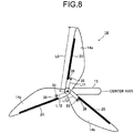
- FIG. 8 is a perspective view illustrating one embodiment of the blades illustrated in FIG. 1 .
- the blades 14 of the fan 10 illustrated in FIG. 1 are plural blades disposed on the rotation shaft 13 so that they are at equal angles from each other in a radial direction of the rotation shaft 13, as illustrated in FIG. 8 for example, and there are three blades 14a to 14c in the embodiment. These blades 14a to 14c are structured integrally with the rotation shaft 13. Note that although the blades 14 of the fan 10 in this embodiment are constituted of three blades, they are not limited thus.
- the airflow generation devices 20 are disposed respectively, and the transformers 33 are disposed respectively in the vicinities of the airflow generation devices 20 and are connected electrically to the airflow generation devices 20.
- the respective transformers 33 are disposed on the respective blades 14a to 14c so that their combined center of gravity substantially matches the center axis of the rotation shaft 13.
- the transformers 33 are disposed respectively on the respective blades 14a to 14c so as to have, for example, substantially the same weight at substantially equal intervals from the center axis of the rotation shaft 13, thereby making the above-described combined center of gravity substantially match the center axis of the rotation shaft 13.
- the substantially match refers to, for example, satisfying L11/L0 ⁇ 5/100 where L11 is the distance between the center axis of the rotation shaft 13 and the combined center of gravity of the transformers 33 of the respective blades 14a to 14c, and L0 is the blade length.
- substantially equal intervals refer to that, for example, the distances from the center axis of the rotation shaft 13 to the transformers 33 of the respective blades 14a to 14c satisfy H11/L0 ⁇ 1/5, L12/L0 ⁇ 1/5, and L13/L0 ⁇ 1/5, respectively.
- the high-frequency high voltage can be supplied to the respective airflow generation devices 20 from the three transformers 33 of small size and light weight, as compared to the case where the high-frequency high voltage is supplied from one transformer 33 having a large weight to the three airflow generation devices 20.
- the high-frequency high voltage can be supplied stably with low noise even while the rotation apparatus is operating.
- the respective transformers 33 can be disposed respectively in the vicinities of the airflow generation devices 20, wires 38 for connecting the transformers 33 and the airflow generation devices 20 can be shortened to be a minimum, and entrance of noise from these wires can be prevented. As a result, the high-frequency high voltage can be supplied more stably with low noise even while the rotation apparatus is operating.
- FIG. 9 is a perspective view illustrating an application of airflow generation devices 20 and transformers 33 disposed on the blades 14 illustrated in FIG. 8 .
- an arrangement structure of the airflow generation devices 20 and the transformers 33 are different from FIG. 8 .
- the airflow generation devices disposed on the respective blades 14a to 14c are divided into, for example, three airflow generation devices 20a to 20c and are disposed respectively thereon.
- transformers 33a to 33c are disposed in the vicinities of the airflow generation devices 20a to 20c respectively, and the transformers 33a to 33c are connected electrically to the airflow generation devices 20a to 20c.
- the plural transformers 33a to 33c are disposed respectively on the respective blades 14a to 14c so that, for example, with the centers of gravity of respective transformers 33b on the respective blades 14a to 14c being obtained, the center of gravity further combining the obtained respective centers of gravity substantially matches the center axis of the rotation shaft 13.
- the transformers 33a to 33c are disposed respectively on the respective blades 14a to 14c so as to have, for example, substantially the same weight at substantially equal intervals from the center axis of the rotation shaft 13, thereby making the above-described combined center of gravity substantially match the center axis of the rotation shaft 13.
- the airflow generation devices 20 disposed on the respective blades 14a to 14c are structured by dividing into three, but it is not limited thus.
- the substantially match refers to, for example, satisfying L1a/L0 ⁇ 5/100 where L1a is the distance between the center axis of the rotation shaft 13 and the combined center of gravity of the transformers 33b of the respective blades 14a to 14c, and L0 is the blade length.
- substantially equal intervals refer to that, for example, the distances from the center axis of the rotation shaft 13 to the transformers 33 of the respective blades 14a to 14c satisfy L1a/L0 ⁇ 115, L1b/L0 ⁇ 1/5, and L1c/L0 ⁇ 1/5, respectively.
- the transformers 33 having a smaller size and less weight than the above-described transformers 33 illustrated in FIG. 8 can be used, and it becomes possible to distribute the weight
- moment applied to the supporting part of the transformer 33 and the rotation center can be suppressed small, and improvement in durability and reduction in vibrations and noise can be achieved.
- the high-frequency high voltage can be supplied stably with low noise even while the rotation apparatus is operating.
- the airflow generation devices 20 and the transformers 33 can be divided and disposed on one blade.
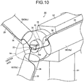
- FIG. 10 is a perspective view illustrating a part of a large windmill 50 of a wind power generation system of MW (megawatt) class of one embodiment.
- the large windmill 50 has a cylindrical tower 51 installed perpendicularly on the ground which is not illustrated, and a rectangular parallelepiped nacelle 52 attached to a top portion of this tower 51 and housing a not-illustrated power generator and so on. Moreover, at a front end of the nacelle 52, a hub 53 and a nose cone 54 are disposed on one end of the nacelle 52. A rotation shaft 55 projecting from the nacelle 52 is provided in a center portion of the hub 53, and a blade 56 is disposed on an outer peripheral surface of the nose cone 54 (or the hub 53). The hub 53 and the nose cone 54 rotate together with the rotation shaft 55.
- This blade 56 has, for example, three blades 56a to 56c, and on surfaces of the blades 56a to 56c, airflow generation devices 20 are disposed respectively to extend in a longitudinal direction of the blades.
- the blades 56a to 56c are disposed on the outer peripheral surface of the nose cone 54 to be at angles substantially equal to each other. Note that although the blade 56 of the large windmill 50 is generally constituted of three blades 56a to 56c, it is not limited thus.
- a transformer 33 and a sliding type transmission unit 35 are provided in an end portion 55a of the nose cone 54 side of the rotation shaft 55.
- the transformer 33 has a large weight, and is disposed in the end portion 55a of the rotation shaft 55 and in a center portion of the hub 53 so that the center of gravity of the transformer substantially matches the center axis of the rotation shaft 55 of the generator (large windmill 50).
- the above-described substantially match refers to that, for example, a distance L between the center axis of the rotation shaft 55 and the center of gravity of the transformer 33 is equal to or smaller than 5% of the blade length L0 (not illustrated) of the blade 56 (see FIG. 1 ).
- the sliding type transmission unit 35 is disposed in the center portion of the rotation shaft 55 similarly to Embodiment 1. Note that the sliding type transmission unit 35 has a small radius of rotation and a light weight, and hence does not affect moment applied to the rotation center of the rotation shaft 13.
- the transformer 33 is disposed in the center portion of the end portion 55a of this rotation shaft 55 so that its center of gravity substantially matches the center axis of the rotation shaft 55, and an AC/DC conversion unit 31 and a high frequency generation unit 32 are disposed on a holding side (nacelle 52) of the large windmill 50. Then, the high frequency generation unit 32 generates a high-frequency alternating voltage based on a direct-current voltage generated in the AC/DC conversion unit 31, and this high-frequency alternating voltage can be supplied to the transformer 33 via the sliding type transmission unit 35. The transformer 33 converts the high-frequency alternating voltage from the sliding type transmission unit 35 into a high-frequency high voltage and outputs it to the airflow generation devices 20.
- the output of the voltage application device for the airflow generation device 20 is about several [kW], and the size and weight of the transformer 33 is large compared to an apparatus in the nose cone 54 of conventional windmills.
- the transformer 33 is disposed in the center portion of the end portion 55a on the nose cone 54 side of the rotation shaft 55 so that its center of gravity substantially matches the center axis of the rotation shaft 55.
- plasma can be generated on the blade 14 without applying a high voltage to the sliding type transmission unit 35 (rings 35a), and improvement in durability, reduction in vibrations and noise, improvement in aerodynamic performance, and the like can be achieved As a result, the high-frequency high voltage can be supplied stably with low noise even while the rotation apparatus is operating.
- the transformer 33 is disposed in the center portion of the end portion 55 a of the rotation shaft 55 so that its center of gravity substantially matches the center axis of the rotation shaft 55, but it is not limited thus.
- the high frequency generation unit 32 may be disposed in the end portion 55a of the rotation shaft 55.
- the AC/DC conversion unit 31 and the high frequency generation unit 32 are disposed on the holding part (bearing 12) side.
- the AC/DC conversion unit 31, the high frequency generation unit 32, or both of them may be disposed on the rotation blade (blades 14) side.
- FIG. 11 is a perspective view illustrating a part of a large windmill 50 of a wind power generation system of MW (megawatt) class of another embodiment.
- the structures of the large windmill 50 and airflow generation devices 20 are similar to those in FIG. 10 , but an arrangement structure of the voltage application device 30 is different.
- transformers 33 are disposed respectively in root portions of respective blades 56a to 56c where they are attached to the nose cone 54 so as to have, for example, substantially the same weight at substantially equal intervals from the center axis of the rotation shaft 55, thereby making the combined center of gravity of the respective transformers 33 substantially match the center axis of the rotation shaft 55.
- the sliding type transmission unit 35 is disposed in the center portion of the end portion 55a on the nose cone 54 side of the rotation shaft 55, making the center of gravity of the sliding type transmission unit 35 substantially match the center axis of the rotation shaft 55.
- the substantially match refers to, for example, satisfying L11/L0 ⁇ 5/100 where L11 is the distance between the center axis of the rotation shaft 13 and the combined center of gravity of the transformers 33 of the respective blades 14a to 14c, and L0 is the blade length.
- substantially equal intervals refer to that, for example, the distances from the center axis of the rotation shaft 13 to the transformers 33 of the respective blades 14a to 14c satisfy L11/L0 ⁇ 1/5, L12/L0 ⁇ 1/5, and L13/L0 ⁇ 1/5, respectively.
- the power supplies are disposed so that the total center of gravity which further combines, regarding all the blades, the combined centers of gravity of the power supplies disposed on the respective blades substantially matches the center axis of the rotation shaft.
- the respective transformers 33 are disposed respectively in the root portions of the blades 56 so that their combined center of gravity substantially matches the center axis of the rotation shaft 55.
- plasma can be generated on the blade 14 without applying a high voltage to the sliding type transmission unit 35 (rings 35a), and improvement in durability, and reduction in vibrations and noise can be achieved.
- the high-frequency high voltage can be supplied stably with low noise even while the rotation apparatus is operating.
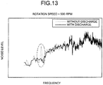
- results of an experiment aiming at noise reduction of the fan are illustrated in FIG. 12 to FIG. 17 . It is conceivable that noise of a fan is generated by a variation in wind velocity in the vicinity of the trailing edge of a rotating blade. Accordingly, the airflow generation device was disposed in the vicinity of the trailing edge of a blade of the fan, and noise in the vicinity of the fan was measured with a microphone to examine the effect of plasma.
- the AC/DC conversion unit, the high frequency generation unit, and the transformer were disposed on the holding side of the fan, and the examination was performed for the case of a conventional method of transmitting the high-frequency high voltage to the rotation side of the fan via a sliding type transmission unit, and a power supply A and a power supply B which will be described later.
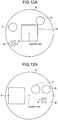
- FIG. 12 is a diagram in which the transformer 33 is disposed in an end portion of a rotation shaft of the fan, where (a) is a diagram in the case of using a voltage application device (hereinafter referred to as "power supply A") in which the transformer 33 is disposed on the center axis of this end portion, and (b) is a diagram in the case of using a voltage application device (hereinafter referred to as "power supply B") in which the transformer 33 is disposed to be deviated from the center axis of this end portion.
- power supply A a voltage application device
- power supply B a voltage application device
- the case of power supply A presents a structure in which the transformer 33 is disposed on the center axis of the end portion of the rotation shaft of the fan so that its center of gravity substantially matches the center axis of the rotation shaft (similarly to the structure of FIG. 5 ).
- the high frequency generation unit 32 in the diagram is formed on a substrate in a disc shape which can be disposed concentrically on the end portion of the rotation shaft 12 (see FIG. 5 ) and is disposed so that its center of gravity substantially matches the center axis of the rotation shaft, and the transformer 33 is mounted on this substrate (the same applies to FIG. 12(b) ).
- the slip ring (see FIG. 5 ) is disposed on the rotation shaft 13 to enable supply of voltage from the holding side to the rotation side (the same applies to FIG. 12(b) ).
- numerals 60 to 62 in the diagrams are circuit elements, such as a diode and a resistor, for generating the high-frequency high voltage. These circuit elements are of light weight, and thus their influence on moment applied to the rotation center of the rotation shaft 13 can be ignored (the same applies to FIG. 12(b) ).
- the case of power supply B presents a structure in which the transformer 33 is disposed to be deviated from the center axis of the end portion of the rotation shaft of the fan so that its center of gravity do not substantially match the center axis of the rotation shaft.
- this power supply B since the transformer 33 having a large weight is deviated from the center axis of the end portion of the rotation shaft, it is conceivable that there appears an influence on moment applied to the rotation center of the rotation shaft 13.
- surface electrodes of the airflow generation device As plasma electrodes of the airflow generation device (see the pair of electrodes 22, 23 illustrated in FIG. 2 ), surface electrodes are formed uniformly in a span direction on a polyimide resin having a thickness of 250 [ ⁇ m]. The discharge length of the surface electrodes is 100 [mm] per blade. The electrodes are disposed so that plasma induced flow occurs toward the trailing edge of the blade. The electrodes are disposed on both the front and rear surfaces of the blade. These conditions are the same in the case of the above-described structure of conventional method, in the case of the structure of power supply A and in the case of the structure of power supply B.
- the present inventors obtained and compared noise spectra with discharge and without discharge using a microphone (not illustrated) disposed at a position 30 [cm] away from the blade of the fan in the structure of power supply A.
- FIG. 13 is a diagram illustrating the noise spectra of the fan.
- the present inventors obtained and compared electromagnetic noise levels, peak intensity which can be reduced by plasma in noise spectrum, vibration intensity and power supply efficiency (discharge power/primary power consumption) in the case of the above-described structure of conventional method, in the case of the structure of power supply A and in the case of the structure of power supply B.
- a dotted line denotes the structure of conventional method
- a solid line denotes the structure of power supply A
- a chain-dashed line denotes the structure of power supply B.
- FIG. 14 is a diagram illustrating comparison results of electromagnetic noise levels. As illustrated in FIG. 14 , the electromagnetic noise levels are clearly lower in the cases of the structures of power supply A (solid line) and power supply B (chain-dashed line) than in the structure of the conventional method (dotted line), and this indicates that the electromagnetic noise is reduced by lowering the supply voltage to the sliding type transmission unit.
- FIG. 15 is a diagram illustrating comparison results of peak intensity which can be reduced by plasma in noise spectrum.
- the peak intensity is reduced stably, but in the case of the structure of power supply B (chain-dashed line), the peak intensity increases gradually and the noise increases rapidly in the middle. This is because noise due to vibrations is large in the state of 500 [rpm] since the transformer 33 is not located on the center axis of the rotation shaft, and this is overlapped on aerodynamic noise as the target.
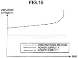
- FIG. 16 is a diagram illustrating comparison results of vibration intensity.
- the vibration intensity illustrated in FIG. 16 was measured with a not-illustrated accelerometer disposed in the casing 11 (see FIG. 5 ) of the fan 10.
- the case of the structure of power supply B (the chain-dashed line in the diagram) is large in vibration compared to the cases of the other structures (dotted line and solid line in the diagram), increases in vibration intensity gradually, and increases rapidly in vibration in the middle. This is because vibrations are large in the state that the rotation speed of the fan 11 (see FIG. 5 ) is 500 [rpm] since the transformer 33 is not located on the center axis of the rotation shaft 13.
- FIG. 17 is a diagram illustrating comparison results of power supply efficiency.
- the power supply efficiency illustrated in FIG. 17 was evaluated by dividing discharge power by primary power consumption. In either case of the structures of power supply A (solid line in the diagram) and power supply B (chain-dashed line in the diagram), the efficiency is higher than the case of the structure of conventional method (dotted line in the diagram). This indicates that heat loss can be reduced and a highly efficient voltage application device 30 can be achieved by avoiding needless discharge in the sliding type transmission unit by reducing the supply voltage to the sliding type transmission unit.
- the combined center of gravity of these transformers 33 substantially matches the center axis of the rotation shaft 13.
Landscapes
- Engineering & Computer Science (AREA)
- Mechanical Engineering (AREA)
- General Engineering & Computer Science (AREA)
- Physics & Mathematics (AREA)
- Combustion & Propulsion (AREA)
- Life Sciences & Earth Sciences (AREA)
- Sustainable Development (AREA)
- Sustainable Energy (AREA)
- Chemical & Material Sciences (AREA)
- Plasma & Fusion (AREA)
- Fluid Mechanics (AREA)
- Power Engineering (AREA)
- General Physics & Mathematics (AREA)
- Automation & Control Theory (AREA)
- Plasma Technology (AREA)
- Wind Motors (AREA)
- Turbine Rotor Nozzle Sealing (AREA)
- Structures Of Non-Positive Displacement Pumps (AREA)
- Electrostatic Spraying Apparatus (AREA)
- Physical Or Chemical Processes And Apparatus (AREA)
Abstract
Description
- Embodiments described herein relate generally to a voltage application device, a rotation apparatus and a voltage application method.
- There has been proposed a voltage supply device such that an airflow generation device using plasma is disposed on the surface of a rotation blade included in a rotation apparatus such as a fan, a windmill or a turbine, and a voltage is supplied to a rotation field. This voltage application device applies a voltage between a first electrode of the airflow generation device provided on the surface of the blade which rotates and a second electrode disposed separately from the first electrode, to thereby generate airflow between the first electrode and the second electrode. Thus, there is exerted an influence on the velocity distribution of a boundary layer on the surface of the rotation blade, and separation is suppressed and variation in flow velocity is reduced, thereby stabilizing the airflow, reducing noise and vibrations, and improving aerodynamic properties of the blade.
- However, it has been found that there is a possibility of electromagnetic noise to be mixed in the airflow generation device. For example, when a high-frequency high voltage is transmitted via a sliding type transmission unit electrically connecting a rotation side and a fixed side of the rotation apparatus, a sliding part of the sliding type transmission unit varies irregularly in contact surface area and contact resistance due to irregularities of the sliding part and unevenness in pressing forces. Accordingly, small discharge occurs in the vicinity of the sliding part corresponding to this variation, and electromagnetic noise due to the discharge occurs. Thus, not only the influence of noise on other devices in the periphery arises, but also the electromagnetic noise mixes into power supplied to the airflow generation device. This causes operation of the airflow generation device to be unstable, and the effects such as reduction in noise and vibrations as well as efficiency improvement cannot be obtained sufficiently. Further, the transmission unit wears out due to the discharge in the sliding type transmission unit, which becomes a factor of increasing running costs.
-
-
FIG. 1 is a side view illustrating a structure of a voltage application device of one embodiment. -
FIG. 2 is a perspective view schematically illustrating an airflow generation device. -
FIG. 3 is a cross-sectional view illustrating an A-A cross section ofFIG. 2 . -
FIG. 4 is a block diagram illustrating a structure of an electric circuit of the voltage application device. -
FIG. 5 is a side view illustrating a structure of a voltage application device of Embodiment 2. -
FIG. 6 is a side view illustrating a structure of a voltage application device of Embodiment 3. -
FIG. 7 is an enlarged cross-sectional view illustrating an attached state of a rotation shaft and a slip ring ofFIG. 6 . -
FIG. 8 is a perspective view illustrating one embodiment of blades illustrated inFIG. 1 . -
FIG. 9 is a perspective view illustrating an application of airflow generation devices and transformers disposed on the blades illustrated inFIG. 8 . -
FIG. 10 is a perspective view illustrating a part of a large windmill of a wind power generation system of one embodiment. -
FIG. 11 is a perspective view illustrating a part of a large windmill of a wind power generation system of another embodiment. -
FIG. 12 is a diagram of the case where a transformer is disposed in an end portion of a rotation shaft of a fan. -
FIG. 13 is a diagram illustrating noise spectra of the fan. -
FIG. 14 is a diagram illustrating comparison results of electromagnetic noise levels. -
FIG. 15 is a diagram illustrating comparison results of peak intensity which can be reduced by plasma in noise spectrum. -
FIG. 16 is a diagram illustrating comparison results of vibration intensity. -
FIG. 17 is a diagram illustrating comparison results of power supply efficiency. - A voltage application device of an embodiment applies a voltage between a first electrode and second electrode disposed separately from each other in an airflow generation device, which are disposed on a rotation blade of a rotation apparatus, in which a rotation shaft of the rotation blade is held rotatably by a holding part. In the voltage application device of the embodiment, a voltage output unit outputs a voltage. Then, a sliding type transmission unit having electrodes disposed respectively on the rotation blade side and the holding part side of the rotation shaft transmits a voltage outputted from the voltage output unit from the holding part side to the rotation blade side. Then, a transformation unit disposed on the rotation blade side increases the voltage transmitted by the sliding type transmission unit and outputs the voltage to the airflow generation device.
- Hereinafter, an embodiment of the present invention will be described with reference to the drawings.
FIG. 1 is a side view illustrating a structure of avoltage application device 30 according to one embodiment. - As illustrated in
FIG. 1 , thisvoltage application device 30 is disposed in afan 10 which is a rotation apparatus. Thisfan 10 is a small fan for household use for example, and has a casing (case) 11, a bearing (holding part) 12 attached to thecasing 11, arotation shaft 13 supported rotatably by thebearing 12, and a plurality of blades (rotation blade) 14 attached to an end portion of therotation shaft 13 and rotating together with therotation shaft 13. On a surface of at least oneblade 14 among the plurality ofblades 14, anairflow generation device 20 generating plasma above theblades 14 is disposed, and a high-frequency high voltage is applied thereto by thevoltage application device 30. -
FIG. 2 is a perspective view schematically illustrating theairflow generation device 20.FIG. 3 is a cross-sectional view illustrating an A-A cross section ofFIG. 2 . - As illustrated in
FIG. 2 andFIG. 3 , theairflow generation device 20 has an electrode 22 (first electrode) exposed on a surface of a dielectric 21, and an electrode 23 (second electrode) which differs from thesecond electrode 22 in distance from the surface of the dielectric 21, is separated by shifting in a horizontal direction from the surface of the dielectric 21, and is embedded in the dielectric 21. Between the pair ofelectrodes voltage application device 30 applying a voltage is connected viacables 24. The dielectric 21 and the pair ofelectrodes blade 14 to extend along a longitudinal direction (seeFIG. 1 ). - In this
airflow generation device 20, when a high-frequency high voltage is applied between the pair ofelectrodes voltage application device 30, discharge occurs between the pair ofelectrodes electrodes airflow 25 flowing in an arrow direction illustrated inFIG. 2 andFIG. 3 can be generated along the surface of theairflow generation device 20, that is, the surface of the dielectric 21. This generatedairflow 25 enables airflow control effects such as flow separation suppression, suppression of noise and vibrations, and the like around theblade 14. -
FIG. 4 is a block diagram illustrating a structure of an electric circuit of thevoltage application device 30. - As illustrated in
FIG. 4 , thevoltage application device 30 includes an AC/DC conversion unit 31 converting an alternating voltage into a direct-current voltage, a highfrequency generation unit 32 generating a high-frequency voltage, and atransformer 33 connected to the highfrequency generation unit 32 via a sliding type transmission unit 35 (seeFIG. 1 ) and generating a high-frequency high voltage. - As illustrated in
FIG. 1 , the AC/DC conversion unit 31 is disposed in thecasing 11. The AC/DC conversion unit 31 converts, for example, a sinusoidal low voltage (AC) of a commercial frequency into a direct-current voltage (DC) via a not-illustrated diode and so on. The AC/DC conversion unit 31 functions as a voltage conversion unit converting an alternating voltage into a direct-current voltage. Note that regarding the alternating voltage, it is desired to use a triphase alternating voltage for suppressing ripples to be low. - The high
frequency generation unit 32 is disposed in thecasing 11 as illustrated inFIG. 1 . The highfrequency generation unit 32 is activated by a direct-current voltage supplied by, for example, switching using a IGBT (Insulated Gate Bipolar Transistor) or FET (Field-Effect Transistor) to generate high frequency pulses, and generate a high-frequency alternating voltage of about 1 [kHz] to 20 [kHz]. The highfrequency generation unit 32 is connected electrically to the slidingtype transmission unit 35 viacables 34. This highfrequency generation unit 32 has a function to generate a high-frequency component based on a direct-current voltage converted by the voltage conversion unit. - The sliding type transmission unit (for example, slip ring) 35 has, as illustrated in
FIG. 1 , two rings (electrodes) 35a attached to therotation shaft 13 of thefan 10 and rotating with thisrotation shaft 13, and two brushes (sliding contacts) 35b paired with therings 35a and connected electrically to the highfrequency generation unit 32. The tworings 35a are disposed on the blades 14 (rotation blade) side and the bearing 12 (holding part) sideon therotation shaft 13, insulated electrically from each other, and both connected to thetransformer 33. In the two pairs of aring 35a and abrush 35b, thering 35a and thebrush 35b are in electrical contact with each other, and have a function to transmit the high-frequency alternating voltage outputted from the highfrequency generation unit 32 to thetransformer 33. That is, the slidingtype transmission unit 35 transmits the voltage from the side of the bearing 12 (holding part) to the side of the blades 14 (rotation blade). Note that the brush may be disposed on the rotation shaft and the ring, which is in electrical contact with the brush, may be disposed on the holding part side. - The
transformer 33 is disposed on therotation shaft 13 on theblades 14 side with respect to therings 35a, as illustrated inFIG. 1 , Thetransformer 33 increases the high-frequency alternating voltage of 100 [v] to 400 [v] for example transmitted from therings 35a to a high-frequency high voltage of several [kV] and outputs the voltage to theairflow generation device 20. Thetransformer 33 is disposed on therotation shaft 13 so that the center of gravity thereof substantially matches a center axis of therotation shaft 13 of thefan 10. Thetransformer 33 has a function to convert the voltage outputted from the slidingtype transmission unit 35 into a high-frequency high voltage and output the voltage to theairflow generation device 20. Note that the above-described substantially match refers to that, for example, a distance L between the center axis of therotation shaft 13 and the center ofgravity 33a of thetransformer 33 is equal to or smaller than 5% of a distance (hereinafter referred to as "blade length") L0 between the center axis of therotation shaft 13 and the front end of theblades 14. - That is, in this embodiment, the
transformer 33 is disposed on, for example, the center axis of an end portion on theblades 14 side of therotation shaft 13 so that the center of gravity thereof substantially matches the center axis of therotation shaft 13, and the AC/DC conversion unit 31 and the highfrequency generation unit 32 are disposed on the holding side (casing 11) of thefan 10. The highfrequency generation unit 32 then generates a high-frequency alternating voltage based on the direct-current voltage generated in the AC/DC conversion unit 31, and this high-frequency alternating voltage can be supplied to thetransformer 33 via the slidingtype transmission unit 35. Thetransformer 33 converts the high-frequency alternating voltage transmitted from the slidingtype transmission unit 35 into a high-frequency high voltage, and outputs it to theairflow generation device 20. - In this
airflow generation device 20, when the high-frequency high voltage is applied from thevoltage application device 30 to the pair ofelectrodes electrodes airflow 25 can be generated along the surface (blade 14) of theairflow generation device 20. - Thus, in this embodiment, the high-frequency high voltage can be applied to the
airflow generation device 20 without applying a high voltage to the sliding type transmission unit 35 (rings 35a). Accordingly, the high-frequency high voltage can be supplied stably with low noise even while the rotation apparatus is operating (see experimental results which will be described later). As a result, operation of the airflow generation device becomes stable, and the airflow around theblades 14 is stabilized, thereby achieving reduction in noise and vibrations. Further, occurrence of noise due to discharge in sliding type contacts can be prevented, and wearing of contacts can be reduced. - Further, in this embodiment, the
transformer 33 having a large weight is disposed on therotation shaft 13 so that its center of gravity substantially matches the center axis of therotation shaft 13. Thus, moment applied to a supporting part of thetransformer 33 and a rotation center can be suppressed small, and improvement in durability and reduction in vibrations and noise can be achieved. - Further, the
transformer 33 is separate from the other parts of thevoltage application device 30. Thetransformer 33 is disposed on the holding part (bearing 12) side, and then the other parts are disposed on the rotation blade (blades 14) side. Thus, an increase of weight of the rotation blade (blades 14) side can be suppressed least. As a result, the simplified structure of thebearing 12, a long life, a low cost, a lowering of moment applied to the rotation part, and simplification of designing can be achieved. - Note that when the input to the
voltage application device 30 is a direct-current voltage, it is possible to provide a DC/DC conversion unit to increase this direct-current voltage to a predetermined voltage value, instead of the AC/DC conversion unit 31. Or when the direct-current voltage inputted to thevoltage application device 30 is of a predetermined voltage value, both the AC/DC conversion unit 31 and the DC/DC conversion unit may be omitted. - By such a structure, it is possible to reduce the number of parts along with reduction in production cost of the
voltage application device 30. For example, when thisvoltage application device 30 is used for a large windmill for wind power generation system which will be described later, it may be possible to extract the above-described direct-current voltage and input it to thevoltage application device 30, which allows to reduce the production cost of the above-describedvoltage application device 30 and the number of parts. -
FIG. 5 is a side view illustrating a structure of thevoltage application device 30 of Embodiment 2. - As illustrated in
FIG. 5 , structures of thefan 10 and theairflow generation device 20 are similar to those inFIG. 1 , but an arrangement structure of thevoltage application device 30 is different. Specifically, in thisvoltage application device 30, among the AC/DC conversion unit 31, the highfrequency generation unit 32 and thetransformer 33 which are necessary for driving theairflow generation device 20, the highfrequency generation unit 32 and thetransformer 33 are disposed on therotation shaft 13 on theblades 14 side with respect to therings 35a. - The high
frequency generation unit 32 and thetransformer 33 are disposed on therotation shaft 13 so that their combined center of gravity substantially matches the center axis of therotation shaft 13 of thefan 10. The direct-current voltage generated in the AC/DC conversion unit 31 is outputted to the highfrequency generation unit 32 via the slidingtype transmission unit 35. - That is, to increase the durability of the brushes, it is desired to make the contact area of the
rings 35a and thebrushes 35b as small as possible. However, when this contact area becomes small, it is possible that application of voltage is momentarily interrupted due to vibrations, wear, and the like. Thus, when the voltage in which interruption of application occurred is supplied as it is to thetransformer 33, a momentary variation occurs also in the voltage supplied to theairflow generation device 20, and stable plasma discharge can no longer be maintained. - Then, by disposing the high
frequency generation unit 32 on therotation shaft 13 on theblades 14 side with respect to the sliding type transmission unit 35 (rings 35a), a filter function which the highfrequency generation unit 32 has for obtaining a predetermined frequency band can be utilized. By this filter function, the momentary variation of the direct-current voltage is no longer transmitted to thetransformer 33, the voltage supplied to theairflow generation device 20 becomes stable, and stable plasma discharge can be maintained. As a result, theairflow 25 can be generated without interruption along the surface of theairflow generation device 20. The generatedairflow 25 allows stable rotation of theblades 14. Note that the structures of the highfrequency generation unit 32 and thetransformer 33 will be described in detail inFIG. 12(a) which will be described later. - Incidentally, this high
frequency generation unit 32 has a filter function for obtaining a predetermined frequency band, but this filter function may be of a separate body. In this case, the filter function, the high frequency generation unit and the transformer are disposed on therotation shaft 13 on theblades 14 side with respect to therings 35a so that their combined center of gravity thereof substantially matches the center axis of therotation shaft 13. Further, it is also possible to dispose only the filter function on therotation shaft 13 on theblades 14 side, and to dispose the highfrequency generation unit 32 on the holding side of thefan 10. Note that the above-described substantially match refers to that, for example, a distance La between the center axis and the combined center of gravity of the highfrequency generation unit 32 and thetransformer 33 is equal to or smaller than 5% of the blade length L0. - That is, in this embodiment, the high
frequency generation unit 32 and thetransformer 33 are disposed on thisrotation shaft 13 so that their combined center of gravity substantially matches the center axis of therotation shaft 13, and the direct-current voltage outputted from the AC/DC conversion unit 31 is supplied to the highfrequency generation unit 32 via the slidingtype transmission unit 35. - Thus, in this embodiment, even when there occurs momentary application interruption of the voltage, the filter function of the high
frequency generation unit 32 prevents the momentary variation of the direct-current voltage from being transmitted to thetransformer 33, and the high-frequency high voltage can be supplied stably with low noise even while the rotation apparatus is operating. As a result, voltage supply to theairflow generation device 20 becomes stable, and stable plasma discharge can be maintained. - Further, in this embodiment, the high
frequency generation unit 32 and thetransformer 33 are disposed on therotation shaft 13 so that their combined center of gravity substantially matches the center axis of therotation shaft 13. Thus, moment applied to the supporting part of thetransformer 33 and the rotation center of therotation shaft 13 can be suppressed small, and improvement in durability and reduction in vibrations and noise can be achieved. - Note that, in this embodiment, the AC/
DC conversion unit 31 is disposed on the holding part (bearing 12) side. However, the AC/DC conversion unit 31 may be disposed on the rotation blade (blades 14) side, and then the sinusoidal low voltage (AC) of a commercial frequency may be supplied to the AC/DC conversion unit 31 via the slidingtype transmission unit 35. -
FIG. 6 is a side view illustrating a structure of thevoltage application device 30 of Embodiment 3.FIG. 7 is an enlarged cross-sectional view illustrating an attached state of therotation shaft 13 and a slip ring (sliding type transmission unit) 35 ofFIG. 6 . - As illustrated in
FIG. 6 andFIG. 7 , the structures of thefan 10 and theairflow generation device 20 are similar to those inFIG. 1 , but an arrangement structure of thevoltage application device 30 is different. Specifically, in thisvoltage application device 30, rings 35a of theslip ring 35 are attached to anend portion 13a on a side opposite to thebearing 12 side of therotation shaft 13, brushes 35b are in electrical contact with therings 35a, and a direct-current voltage outputted from the AC/DC conversion unit 31 is supplied to the highfrequency generation unit 32 via the slidingtype transmission unit 35. - An attachment state of the
rotation shaft 13 and theslip ring 35 will be described. As illustrated inFIG. 7 , therings 35a of theslip ring 35 are disposed and fixed onto one end side in a longitudinal direction of anattachment shaft 35c. Further, ahole 13b in which an end of theattachment shaft 35c can fit is provided in a center portion of theend portion 13a of therotation shaft 13. - Upon attachment, the other end in the longitudinal direction of the
attachment shaft 35c is inserted and fitted in thehole 13b of theend portion 13a of therotation shaft 13, and further, theattachment shaft 35c can be fixed to theend portion 13a of therotation shaft 13 using ascrew 40. - Thus, in this embodiment, the
attachment shaft 35c to which therings 35a are fixed is fitted in thehole 13b of theend portion 13a of therotation shaft 13. Thus, the radius of rotation of therings 35a can be made small and a sliding distance per rotation can be made short, as compared to the case ofFIG. 1 where therings 35a are attached directly to therotation shaft 13. In the case ofFIG. 1 , therotation shaft 13 needs to mechanically support the rotational structure of thefan 10, and hence is one having a round bar shape with a necessary thickness. When theslip ring 35 is disposed thereon as inFIG. 1 , it is necessary to make the diameter of therings 35a larger than the diameter of the round bar, and a sliding distance per rotation becomes large. In the structure as illustrated inFIG. 7 , the round bar to which theslip ring 35 is attached becomes as denoted by 35c, and this round bar just needs to have strength for supporting only the rotational structure of theslip ring 35. Accordingly, a thin round bar can be used, and the diameter of therings 35a to be attached thereto can also be made small, making the sliding distance per rotation short. - Thus, the wearing ratio of the
brushes 35b when therotation shaft 13 is rotated at the same rotation speed can be reduced more than in the case ofFIG. 1 , and the usable life of the slidingtype transmission unit 35 can be improved. - Further, in this embodiment, similarly to Embodiment 1, the high-frequency high voltage can be supplied stably with low noise even while the rotation apparatus is operating.
- Also in this embodiment, the high
frequency generation unit 32 and thetransformer 33 are disposed on therotation shaft 13 so that their combined center of gravity substantially matches the center axis of therotation shaft 13. Thus, moment applied to the supporting part of thetransformer 33 and the rotation center of therotation shaft 13 can be suppressed small, and improvement in durability and reduction in vibrations and noise can be achieved. - Note that also in this embodiment, similarly to Embodiment 2, the above-described substantially match refers to that, for example, the distance La between the center axis and the combined center of gravity of the high
frequency generation unit 32 and thetransformer 33 is equal to or smaller than 5% of the blade length L0 (seeFIG. 5 ). - Further, in this embodiment, the AC/
DC conversion unit 31 is disposed on the holding part (bearing 12) side. However, the AC/DC conversion unit 31 may be disposed on the rotation blade (blades 14) side, and then the sinusoidal low voltage (AC) of a commercial frequency may be supplied to the AC/DC conversion unit 31 via the slidingtype transmission unit 35. -
FIG. 8 is a perspective view illustrating one embodiment of the blades illustrated inFIG. 1 . Theblades 14 of thefan 10 illustrated inFIG. 1 are plural blades disposed on therotation shaft 13 so that they are at equal angles from each other in a radial direction of therotation shaft 13, as illustrated inFIG. 8 for example, and there are threeblades 14a to 14c in the embodiment. Theseblades 14a to 14c are structured integrally with therotation shaft 13. Note that although theblades 14 of thefan 10 in this embodiment are constituted of three blades, they are not limited thus. - On surfaces of the
respective blades 14a to 14c theairflow generation devices 20 are disposed respectively, and thetransformers 33 are disposed respectively in the vicinities of theairflow generation devices 20 and are connected electrically to theairflow generation devices 20. Therespective transformers 33 are disposed on therespective blades 14a to 14c so that their combined center of gravity substantially matches the center axis of therotation shaft 13. In this embodiment, thetransformers 33 are disposed respectively on therespective blades 14a to 14c so as to have, for example, substantially the same weight at substantially equal intervals from the center axis of therotation shaft 13, thereby making the above-described combined center of gravity substantially match the center axis of therotation shaft 13. - Note that the substantially match refers to, for example, satisfying L11/L0 ≤ 5/100 where L11 is the distance between the center axis of the
rotation shaft 13 and the combined center of gravity of thetransformers 33 of therespective blades 14a to 14c, and L0 is the blade length. - Further, the substantially equal intervals refer to that, for example, the distances from the center axis of the
rotation shaft 13 to thetransformers 33 of therespective blades 14a to 14c satisfy H11/L0 ≤ 1/5, L12/L0 ≤ 1/5, and L13/L0 ≤ 1/5, respectively. - In this embodiment, the high-frequency high voltage can be supplied to the respective
airflow generation devices 20 from the threetransformers 33 of small size and light weight, as compared to the case where the high-frequency high voltage is supplied from onetransformer 33 having a large weight to the threeairflow generation devices 20. Thus, it becomes possible to distribute the weight, moment applied to the supporting part of thetransformer 33 and the rotation center of therotation shaft 13 can be suppressed small, and improvement in durability and reduction in vibrations and noise can be achieved. As a result, the high-frequency high voltage can be supplied stably with low noise even while the rotation apparatus is operating. - Further, in this embodiment, since the
respective transformers 33 can be disposed respectively in the vicinities of theairflow generation devices 20,wires 38 for connecting thetransformers 33 and theairflow generation devices 20 can be shortened to be a minimum, and entrance of noise from these wires can be prevented. As a result, the high-frequency high voltage can be supplied more stably with low noise even while the rotation apparatus is operating. -
FIG. 9 is a perspective view illustrating an application ofairflow generation devices 20 andtransformers 33 disposed on theblades 14 illustrated inFIG. 8 . In this application, an arrangement structure of theairflow generation devices 20 and thetransformers 33 are different fromFIG. 8 . - Specifically, as illustrated in
FIG. 9 , in this application, the airflow generation devices disposed on therespective blades 14a to 14c are divided into, for example, threeairflow generation devices 20a to 20c and are disposed respectively thereon. Accompanying this,transformers 33a to 33c are disposed in the vicinities of theairflow generation devices 20a to 20c respectively, and thetransformers 33a to 33c are connected electrically to theairflow generation devices 20a to 20c. - The
plural transformers 33a to 33c are disposed respectively on therespective blades 14a to 14c so that, for example, with the centers of gravity ofrespective transformers 33b on therespective blades 14a to 14c being obtained, the center of gravity further combining the obtained respective centers of gravity substantially matches the center axis of therotation shaft 13. In this embodiment, thetransformers 33a to 33c are disposed respectively on therespective blades 14a to 14c so as to have, for example, substantially the same weight at substantially equal intervals from the center axis of therotation shaft 13, thereby making the above-described combined center of gravity substantially match the center axis of therotation shaft 13. - Note that in this application, the
airflow generation devices 20 disposed on therespective blades 14a to 14c are structured by dividing into three, but it is not limited thus. Further, also in this application, similarly to Embodiment 4, the substantially match refers to, for example, satisfying L1a/L0 ≤ 5/100 where L1a is the distance between the center axis of therotation shaft 13 and the combined center of gravity of thetransformers 33b of therespective blades 14a to 14c, and L0 is the blade length. - Further, the substantially equal intervals refer to that, for example, the distances from the center axis of the
rotation shaft 13 to thetransformers 33 of therespective blades 14a to 14c satisfy L1a/L0 ≤ 115, L1b/L0 ≤ 1/5, and L1c/L0 ≤ 1/5, respectively. - In this application, the
transformers 33 having a smaller size and less weight than the above-describedtransformers 33 illustrated inFIG. 8 can be used, and it becomes possible to distribute the weight Thus, moment applied to the supporting part of thetransformer 33 and the rotation center can be suppressed small, and improvement in durability and reduction in vibrations and noise can be achieved. As a result, the high-frequency high voltage can be supplied stably with low noise even while the rotation apparatus is operating. - Further, in this application, the
airflow generation devices 20 and thetransformers 33 can be divided and disposed on one blade. Thus, it is possible to use airflow generation devices and transformers which have a smaller size and less weight and cost less than theairflow generation devices 20 and thetransformers 33 of Embodiment 4 illustrated inFIG. 8 . -
FIG. 10 is a perspective view illustrating a part of alarge windmill 50 of a wind power generation system of MW (megawatt) class of one embodiment. - As illustrated in
FIG. 10 , thelarge windmill 50 has acylindrical tower 51 installed perpendicularly on the ground which is not illustrated, and arectangular parallelepiped nacelle 52 attached to a top portion of thistower 51 and housing a not-illustrated power generator and so on. Moreover, at a front end of thenacelle 52, ahub 53 and anose cone 54 are disposed on one end of thenacelle 52. Arotation shaft 55 projecting from thenacelle 52 is provided in a center portion of thehub 53, and ablade 56 is disposed on an outer peripheral surface of the nose cone 54 (or the hub 53). Thehub 53 and thenose cone 54 rotate together with therotation shaft 55. - This
blade 56 has, for example, threeblades 56a to 56c, and on surfaces of theblades 56a to 56c,airflow generation devices 20 are disposed respectively to extend in a longitudinal direction of the blades. Theblades 56a to 56c are disposed on the outer peripheral surface of thenose cone 54 to be at angles substantially equal to each other. Note that although theblade 56 of thelarge windmill 50 is generally constituted of threeblades 56a to 56c, it is not limited thus. - In an
end portion 55a of thenose cone 54 side of therotation shaft 55, atransformer 33 and a slidingtype transmission unit 35 are provided. - The
transformer 33 has a large weight, and is disposed in theend portion 55a of therotation shaft 55 and in a center portion of thehub 53 so that the center of gravity of the transformer substantially matches the center axis of therotation shaft 55 of the generator (large windmill 50). Note that similarly to Embodiment 1, the above-described substantially match refers to that, for example, a distance L between the center axis of therotation shaft 55 and the center of gravity of thetransformer 33 is equal to or smaller than 5% of the blade length L0 (not illustrated) of the blade 56 (seeFIG. 1 ). - The sliding
type transmission unit 35 is disposed in the center portion of therotation shaft 55 similarly to Embodiment 1. Note that the slidingtype transmission unit 35 has a small radius of rotation and a light weight, and hence does not affect moment applied to the rotation center of therotation shaft 13. - That is, in this embodiment, the
transformer 33 is disposed in the center portion of theend portion 55a of thisrotation shaft 55 so that its center of gravity substantially matches the center axis of therotation shaft 55, and an AC/DC conversion unit 31 and a highfrequency generation unit 32 are disposed on a holding side (nacelle 52) of thelarge windmill 50. Then, the highfrequency generation unit 32 generates a high-frequency alternating voltage based on a direct-current voltage generated in the AC/DC conversion unit 31, and this high-frequency alternating voltage can be supplied to thetransformer 33 via the slidingtype transmission unit 35. Thetransformer 33 converts the high-frequency alternating voltage from the slidingtype transmission unit 35 into a high-frequency high voltage and outputs it to theairflow generation devices 20. - In the
airflow generation devices 20, when the high-frequency high voltage from thevoltage application device 30 is applied between a pair ofelectrodes 22, 23 (seeFIG. 2 andFIG. 3 ), discharge occurs between this pair ofelectrodes FIG. 2 andFIG. 3 ) can be generated along the surface (blade 56) of theairflow generation device 20. - In this
large windmill 50, the output of the voltage application device for theairflow generation device 20 is about several [kW], and the size and weight of thetransformer 33 is large compared to an apparatus in thenose cone 54 of conventional windmills. - Accordingly, in this embodiment, the
transformer 33 is disposed in the center portion of theend portion 55a on thenose cone 54 side of therotation shaft 55 so that its center of gravity substantially matches the center axis of therotation shaft 55. Thus, increase in inertial moment of a not-illustrated windmill rotor is suppressed, increase in time constant of rotation of the windmill is suppressed, and the following ability of thelarge windmill 50 at the time of wind velocity/wind direction variation or cut in/cut out can be retained. - Thus, in this embodiment, plasma can be generated on the
blade 14 without applying a high voltage to the sliding type transmission unit 35 (rings 35a), and improvement in durability, reduction in vibrations and noise, improvement in aerodynamic performance, and the like can be achieved As a result, the high-frequency high voltage can be supplied stably with low noise even while the rotation apparatus is operating. - Note that in this embodiment, although only the
transformer 33 is disposed in the center portion of theend portion 55 a of therotation shaft 55 so that its center of gravity substantially matches the center axis of therotation shaft 55, but it is not limited thus. Similarly toFIG. 5 , the highfrequency generation unit 32 may be disposed in theend portion 55a of therotation shaft 55. - Further, in this embodiment, the AC/
DC conversion unit 31 and the highfrequency generation unit 32 are disposed on the holding part (bearing 12) side. However, the AC/DC conversion unit 31, the highfrequency generation unit 32, or both of them may be disposed on the rotation blade (blades 14) side. -
FIG. 11 is a perspective view illustrating a part of alarge windmill 50 of a wind power generation system of MW (megawatt) class of another embodiment. - As illustrated in
FIG. 11 , the structures of thelarge windmill 50 andairflow generation devices 20 are similar to those inFIG. 10 , but an arrangement structure of thevoltage application device 30 is different. - That is, in this embodiment,
transformers 33 are disposed respectively in root portions ofrespective blades 56a to 56c where they are attached to thenose cone 54 so as to have, for example, substantially the same weight at substantially equal intervals from the center axis of therotation shaft 55, thereby making the combined center of gravity of therespective transformers 33 substantially match the center axis of therotation shaft 55. - Moreover, in this embodiment, the sliding
type transmission unit 35 is disposed in the center portion of theend portion 55a on thenose cone 54 side of therotation shaft 55, making the center of gravity of the slidingtype transmission unit 35 substantially match the center axis of therotation shaft 55. - Note that the substantially match refers to, for example, satisfying L11/L0 ≤ 5/100 where L11 is the distance between the center axis of the
rotation shaft 13 and the combined center of gravity of thetransformers 33 of therespective blades 14a to 14c, and L0 is the blade length. - Further, the substantially equal intervals refer to that, for example, the distances from the center axis of the
rotation shaft 13 to thetransformers 33 of therespective blades 14a to 14c satisfy L11/L0 ≤ 1/5, L12/L0 ≤ 1/5, and L13/L0 ≤ 1/5, respectively. - Further, when plural electrodes are disposed on one blade and control of discharge is respectively performed separately, it is necessary to provide a power supply for each electrode. For example, there is a case where three electrodes are driven with three power supplies. In this case, by disposing the three power supplies at substantially equal intervals on the circumference of a cylindrical blade root where a
power supply 33 is provided inFIG. 11 , it is possible to prevent the center of gravity from becoming off balance when the blade root is rotated at the time of pitch control of the blade. In this case, the power supplies are disposed so that the total center of gravity which further combines, regarding all the blades, the combined centers of gravity of the power supplies disposed on the respective blades substantially matches the center axis of the rotation shaft. - In this embodiment, the
respective transformers 33 are disposed respectively in the root portions of theblades 56 so that their combined center of gravity substantially matches the center axis of therotation shaft 55. Thus, increase in inertial moment of a not-illustrated windmill rotor is suppressed, increase in time constant of rotation of the windmill is suppressed, and the following ability of thelarge windmill 50 at the time of wind velocity/wind direction variation or cut in/cut out can be retained. - Thus, in this embodiment, plasma can be generated on the
blade 14 without applying a high voltage to the sliding type transmission unit 35 (rings 35a), and improvement in durability, and reduction in vibrations and noise can be achieved. As a result, the high-frequency high voltage can be supplied stably with low noise even while the rotation apparatus is operating. - Next, results of an experiment as ground which led to the ideas of the above-described embodiments will be described.
- In this experiment, a fan having the structure illustrated in
FIG. 5 (rotation speed = 500 [rpm]) and a power supply (100 [W], 3 [kg]) for high-frequency high voltage (15 [kHz], Vop = 3 [kV]) were prepared to perform verification. Note that the weight of thetransformer 33 was 1 [kg] and the weight of the highfrequency generation unit 32 was 0.2 [kg]. - First, results of an experiment aiming at noise reduction of the fan are illustrated in
FIG. 12 to FIG. 17 . It is conceivable that noise of a fan is generated by a variation in wind velocity in the vicinity of the trailing edge of a rotating blade. Accordingly, the airflow generation device was disposed in the vicinity of the trailing edge of a blade of the fan, and noise in the vicinity of the fan was measured with a microphone to examine the effect of plasma. - Regarding the structure of the voltage application device, the AC/DC conversion unit, the high frequency generation unit, and the transformer were disposed on the holding side of the fan, and the examination was performed for the case of a conventional method of transmitting the high-frequency high voltage to the rotation side of the fan via a sliding type transmission unit, and a power supply A and a power supply B which will be described later.
-
FIG. 12 is a diagram in which thetransformer 33 is disposed in an end portion of a rotation shaft of the fan, where (a) is a diagram in the case of using a voltage application device (hereinafter referred to as "power supply A") in which thetransformer 33 is disposed on the center axis of this end portion, and (b) is a diagram in the case of using a voltage application device (hereinafter referred to as "power supply B") in which thetransformer 33 is disposed to be deviated from the center axis of this end portion. - As illustrated in
FIG. 12(a) , the case of power supply A presents a structure in which thetransformer 33 is disposed on the center axis of the end portion of the rotation shaft of the fan so that its center of gravity substantially matches the center axis of the rotation shaft (similarly to the structure ofFIG. 5 ). Further, the highfrequency generation unit 32 in the diagram is formed on a substrate in a disc shape which can be disposed concentrically on the end portion of the rotation shaft 12 (seeFIG. 5 ) and is disposed so that its center of gravity substantially matches the center axis of the rotation shaft, and thetransformer 33 is mounted on this substrate (the same applies toFIG. 12(b) ). Further, the slip ring (seeFIG. 5 ) is disposed on therotation shaft 13 to enable supply of voltage from the holding side to the rotation side (the same applies toFIG. 12(b) ). - Further,
numerals 60 to 62 in the diagrams are circuit elements, such as a diode and a resistor, for generating the high-frequency high voltage. These circuit elements are of light weight, and thus their influence on moment applied to the rotation center of therotation shaft 13 can be ignored (the same applies toFIG. 12(b) ). - Here, when the
voltage application device 30 was driven, it was possible to generate plasma stably. Even when the rotation speed of the fan is increased to 1500 [rpm], it was still possible to generate plasma stably. - Further, as illustrated in
FIG. 12(b) , the case of power supply B presents a structure in which thetransformer 33 is disposed to be deviated from the center axis of the end portion of the rotation shaft of the fan so that its center of gravity do not substantially match the center axis of the rotation shaft. In the case of this power supply B, since thetransformer 33 having a large weight is deviated from the center axis of the end portion of the rotation shaft, it is conceivable that there appears an influence on moment applied to the rotation center of therotation shaft 13. - As plasma electrodes of the airflow generation device (see the pair of
electrodes FIG. 2 ), surface electrodes are formed uniformly in a span direction on a polyimide resin having a thickness of 250 [µm]. The discharge length of the surface electrodes is 100 [mm] per blade. The electrodes are disposed so that plasma induced flow occurs toward the trailing edge of the blade. The electrodes are disposed on both the front and rear surfaces of the blade. These conditions are the same in the case of the above-described structure of conventional method, in the case of the structure of power supply A and in the case of the structure of power supply B. - First, the present inventors obtained and compared noise spectra with discharge and without discharge using a microphone (not illustrated) disposed at a position 30 [cm] away from the blade of the fan in the structure of power supply A.
-
FIG. 13 is a diagram illustrating the noise spectra of the fan. - As illustrated in
FIG. 13 , in this experiment, under the condition that the rotation speed of the fan is 500 [rpm], regarding the peak of noise occurring when there is no plasma discharge (a dotted line portion in the diagram), reduction of the peak of noise as circled with a chain-dashed line was observed when there is plasma discharge (a solid line portion in the diagram). Thus, it was made clear that the noise of rotation blades can be reduced by plasma airflow control. - Next, the present inventors obtained and compared electromagnetic noise levels, peak intensity which can be reduced by plasma in noise spectrum, vibration intensity and power supply efficiency (discharge power/primary power consumption) in the case of the above-described structure of conventional method, in the case of the structure of power supply A and in the case of the structure of power supply B. Note that in following
FIG. 14 to FIG. 17 , a dotted line denotes the structure of conventional method, a solid line denotes the structure of power supply A, and a chain-dashed line denotes the structure of power supply B. -
FIG. 14 is a diagram illustrating comparison results of electromagnetic noise levels. As illustrated inFIG. 14 , the electromagnetic noise levels are clearly lower in the cases of the structures of power supply A (solid line) and power supply B (chain-dashed line) than in the structure of the conventional method (dotted line), and this indicates that the electromagnetic noise is reduced by lowering the supply voltage to the sliding type transmission unit. -
FIG. 15 is a diagram illustrating comparison results of peak intensity which can be reduced by plasma in noise spectrum. As illustrated inFIG. 15 , in the case of the structure of power supply A (solid line), the peak intensity is reduced stably, but in the case of the structure of power supply B (chain-dashed line), the peak intensity increases gradually and the noise increases rapidly in the middle. This is because noise due to vibrations is large in the state of 500 [rpm] since thetransformer 33 is not located on the center axis of the rotation shaft, and this is overlapped on aerodynamic noise as the target. - Further, at the point of the rapid increase, the fixing part of the
transformer 33 was about to break in the case of the structure of power supply B and then broke eventually, and hence the test was stopped. The case of the structure of conventional method (dotted line) is stable but produces more noise than the case of power supply A. This is because discharge sound in the sliding type transmission unit is overlapped. The above results indicate that the peak intensity of noise can be reduced stably by lowering the supply voltage to the sliding type transmission unit and disposing thetransformer 33 on the center axis of the rotation shaft. -
FIG. 16 is a diagram illustrating comparison results of vibration intensity. The vibration intensity illustrated inFIG. 16 was measured with a not-illustrated accelerometer disposed in the casing 11 (seeFIG. 5 ) of thefan 10. - The case of the structure of power supply B (the chain-dashed line in the diagram) is large in vibration compared to the cases of the other structures (dotted line and solid line in the diagram), increases in vibration intensity gradually, and increases rapidly in vibration in the middle. This is because vibrations are large in the state that the rotation speed of the fan 11 (see
FIG. 5 ) is 500 [rpm] since thetransformer 33 is not located on the center axis of therotation shaft 13. - Further, at the point of the rapid increase, the fixing part of the
transformer 33 of power supply B was about to break and then broke eventually, and hence the test was stopped. The above results indicate that noise can be reduced and a highly reliablevoltage application device 30 can be achieved by disposing thetransformer 33 on the center axis of the rotation shaft. -
FIG. 17 is a diagram illustrating comparison results of power supply efficiency. The power supply efficiency illustrated inFIG. 17 was evaluated by dividing discharge power by primary power consumption. In either case of the structures of power supply A (solid line in the diagram) and power supply B (chain-dashed line in the diagram), the efficiency is higher than the case of the structure of conventional method (dotted line in the diagram). This indicates that heat loss can be reduced and a highly efficientvoltage application device 30 can be achieved by avoiding needless discharge in the sliding type transmission unit by reducing the supply voltage to the sliding type transmission unit. - According to the above-described comparison results, it was found that by disposing on the
rotation shaft 13 at least thetransformer 33 in thevoltage application device 30 so that its center of gravity substantially matches the center axis of therotation shaft 13, a high-frequency high voltage needed in theairflow generation device 20 can be supplied stably and efficiently with low noise from the holding side onto the rotating blades, and reliability increases even under inertial forces by a rotation field. - Further, also when at least the
transformers 33 in thevoltage application device 30 are disposed in a distributed manner onplural blades 14, the combined center of gravity of thesetransformers 33 substantially matches the center axis of therotation shaft 13. Thus, similarly to the above, it is easily conceivable that a high-frequency high voltage needed in theairflow generation devices 20 which are disposed in a distributed manner on therespective blades 14 can be supplied efficiently and stably with low noise from the holding side onto the rotating blades, and reliability increases even under inertial forces by a rotation field. - While certain embodiments have been described, these embodiments have been presented by way of example only, and are not intended to limit the scope of the inventions. Indeed, the novel embodiments described herein may be embodied in a variety of other forms; furthermore, various omissions, substitutions and changes in the form of the embodiments described herein may be made without departing from the spirit of the inventions. The accompanying claims and their equivalents are intended to cover such forms or modifications as would fall within the scope and spirit of the inventions.
- Further disclosure is given in the numbered paragraphs below:
- 1. A voltage application device for applying a voltage between a first electrode and a second electrode disposed separately from each other in an airflow generation device, configured to be disposed on a rotation blade of a rotation apparatus, also configured to provide a rotation shaft of the rotation blade held rotatably by a holding part, the voltage application device, comprising:
- a voltage output unit outputting a voltage;
- a sliding type transmission unit having electrodes disposed respectively on the rotation blade side and the holding part side of the rotation shaft and transmitting a voltage supplied from the holding part side from the holding part side to the rotation blade side; and
- a transformation unit disposed on the rotation blade side, increasing the voltage transmitted by the sliding type transmission unit and outputting the voltage to the airflow generation device.
- 2. The voltage application device according to para. 1, wherein the voltage output unit comprises:
- a voltage conversion unit converting a voltage of a commercial frequency into a direct-current voltage; and
- an alternating voltage generation unit generating an alternating voltage based on the direct-current voltage converted by the voltage conversion unit.
- 3. The voltage application device according to para. 1 or 2,
wherein the voltage output unit is disposed on the holding part side. - 4. The voltage application device according to para. 1 or 2,
wherein the voltage output unit is disposed on the rotation blade side. - 5. The voltage application device according to para. 2, 3 or 4,
wherein the alternating voltage generation unit of the voltage output unit is disposed on the rotation blade side. - 6. The voltage application device according to any one of the preceding paras.,
wherein an equipment disposed on the rotation blade side among the voltage output unit, the transformation unit, and the airflow generation device are disposed on the rotation blade side so that a combined center of gravity thereof substantially matches a center axis of the rotation shaft. - 7. The voltage application device according to any one of the preceding paras., wherein the transformation unit is disposed on the rotation shaft so that a center of gravity thereof substantially matches a center axis of the rotation shaft.
- 8. The voltage application device according to any one of the preceding paras., wherein the rotation blade has at least two blades; and
wherein the airflow generation device and the transformation unit are disposed in each of the blades so that a combined center of gravity thereof substantially matches a center axis of the rotation shaft. - 9. The voltage application device according to any one of the preceding paras. 1 to 6, wherein the rotation blade has at least two blades; and
wherein the airflow generation device and the transformation unit are disposed in each of the blades so as to have a same weight at substantially equal intervals from a center axis of the rotation shaft. - 10. The voltage application device according to any one of the preceding paras., wherein, in the sliding type transmission unit, the electrodes have a ring and a brush in electrical contact with the ring.
- 11. A rotation apparatus comprising the voltage application device according to any one of the preceding claims,
- 12. A voltage application method for applying a voltage between a first electrode and a second electrode disposed separately from each other in an airflow generation device, configured to be disposed on a rotation blade of a rotation apparatus, also configured to provide a rotation shaft of the rotation blade held rotatably by a holding part, the voltage application method, comprising:
- outputting a voltage by a voltage output unit;
transmitting, by a sliding type transmission unit having electrodes disposed respectively on the rotation blade side and the holding part side of the rotation shaft, a voltage supplied from the holding part side; and - increasing, by a transformation unit disposed on the rotation blade side, the transmitted voltage and outputting the voltage to the airflow generation device.
- outputting a voltage by a voltage output unit;
Claims (5)
- A rotation apparatus (10) comprising:a holding part (12);a rotation shaft (13) held rotatably by the holding part;a plurality of rotation blades (14) being attached to the rotation shaft and having a length (L0);a plurality of airflow generation devices (20), each being disposed on respective rotation blade (14) and including a first electrode (22) and a second electrode (23) disposed separately from each other;an AC/DC conversion unit (31) for converting a alternating voltage of a commercial frequency into a direct-current voltage;a high frequency generation unit (32) for generating a high frequency alternating voltage based on the direct-current voltage converted by the AC/DC conversion unit;slip rings (35) for transmitting the alternating voltage, the direct current voltage, or the high frequency alternating voltage from a stationary part to a rotation part; anda plurality of transformers (33) disposed in the rotation blades and for increasing the alternating voltage generated by the high frequency generation unit (32) and outputting the increased voltage between the first electrode (22) and the second electrode (23),wherein a ration of a distance (L) against the length (L0) is 0.05 or less, the distance (L) being defined by a distance between a combined center of gravity of the transformers and a center axis of the rotation shaft.
- The rotation apparatus in accordance with claim 1, wherein the slip rings transmit the alternating voltage to the AC/DC conversion unit.
- The rotation apparatus in accordance with claim 1, wherein the slip rings transmit the direct current voltage from the AC/DC conversion unit.
- The rotation apparatus in accordance with claim 1, wherein the slip rings transmit the high frequency voltage from the high frequency generation unit.
- The rotation apparatus according to any one of claims 1-4, wherein the slip rings comprise a ring (35a) and a brush (35b) in electrical contact with the ring.
Applications Claiming Priority (2)
| Application Number | Priority Date | Filing Date | Title |
|---|---|---|---|
| JP2011108537 | 2011-05-13 | ||
| EP12159457.6A EP2522859B1 (en) | 2011-05-13 | 2012-03-14 | Voltage application device and rotation apparatus |
Related Parent Applications (2)
| Application Number | Title | Priority Date | Filing Date |
|---|---|---|---|
| EP12159457.6A Division EP2522859B1 (en) | 2011-05-13 | 2012-03-14 | Voltage application device and rotation apparatus |
| EP12159457.6A Division-Into EP2522859B1 (en) | 2011-05-13 | 2012-03-14 | Voltage application device and rotation apparatus |
Publications (2)
| Publication Number | Publication Date |
|---|---|
| EP3388687A1 true EP3388687A1 (en) | 2018-10-17 |
| EP3388687B1 EP3388687B1 (en) | 2019-11-06 |
Family
ID=45952860
Family Applications (2)
| Application Number | Title | Priority Date | Filing Date |
|---|---|---|---|
| EP18173177.9A Active EP3388687B1 (en) | 2011-05-13 | 2012-03-14 | Voltage application device, rotation apparatus and voltage application method |
| EP12159457.6A Not-in-force EP2522859B1 (en) | 2011-05-13 | 2012-03-14 | Voltage application device and rotation apparatus |
Family Applications After (1)
| Application Number | Title | Priority Date | Filing Date |
|---|---|---|---|
| EP12159457.6A Not-in-force EP2522859B1 (en) | 2011-05-13 | 2012-03-14 | Voltage application device and rotation apparatus |
Country Status (5)
| Country | Link |
|---|---|
| US (2) | US8937799B2 (en) |
| EP (2) | EP3388687B1 (en) |
| JP (1) | JP5766645B2 (en) |
| KR (1) | KR101277163B1 (en) |
| DK (1) | DK3388687T3 (en) |
Families Citing this family (16)
| Publication number | Priority date | Publication date | Assignee | Title |
|---|---|---|---|---|
| KR101277163B1 (en) * | 2011-05-13 | 2013-06-19 | 가부시끼가이샤 도시바 | Apparatus for supplying voltage, rotation machine and method for supplying voltage |
| JP6021703B2 (en) * | 2013-03-21 | 2016-11-09 | 株式会社東芝 | Wind power generation system |
| JP6403156B2 (en) * | 2014-10-28 | 2018-10-10 | 東芝エネルギーシステムズ株式会社 | Airflow generator and wind power generation system |
| EP3018343B1 (en) | 2014-11-06 | 2018-09-26 | Kabushiki Kaisha Toshiba | Airflow generation device and wind power generation system |
| JP2016098787A (en) * | 2014-11-26 | 2016-05-30 | 株式会社東芝 | Wind farm and wind power generation system |
| JP6523065B2 (en) * | 2015-06-12 | 2019-05-29 | 株式会社東芝 | Airflow generator and wind power generation system |
| JP2017008834A (en) * | 2015-06-23 | 2017-01-12 | 株式会社東芝 | Electric power source for air current generator and wind power generation apparatus |
| USD770027S1 (en) * | 2015-06-30 | 2016-10-25 | Delta T Corporation | Fan |
| USD797917S1 (en) | 2015-08-17 | 2017-09-19 | Delta T Corporation | Fan with light |
| US9771146B2 (en) * | 2015-09-24 | 2017-09-26 | The Boeing Company | Embedded dielectric structures for active flow control plasma sources |
| CN105201891B (en) * | 2015-09-25 | 2018-03-30 | 上海外高桥发电有限责任公司 | Frequency conversion and movable vane combined control system for adjusting rotor blade air-introduced machine |
| USD847969S1 (en) | 2016-01-04 | 2019-05-07 | Delta T, Llc | Fan canopy |
| WO2018216767A1 (en) * | 2017-05-26 | 2018-11-29 | 株式会社朝日ラバー | Airflow generation device and manufacturing method for same |
| KR102521422B1 (en) * | 2018-03-08 | 2023-04-14 | 엘지전자 주식회사 | Fan |
| CN111022382B (en) * | 2019-12-05 | 2020-11-27 | 中国人民解放军空军工程大学 | Method and device for regulating and controlling laminar flow blade type shock wave/boundary layer interference of supersonic compressor by using arc discharge plasma exciter |
| CN113606177B (en) * | 2021-08-20 | 2022-07-08 | 重庆长安汽车股份有限公司 | Method for testing and calculating service life of brushed fan |
Citations (3)
| Publication number | Priority date | Publication date | Assignee | Title |
|---|---|---|---|---|
| US20040011917A1 (en) * | 2002-07-18 | 2004-01-22 | Saeks Richard E. | Shock wave modification via shock induced ion doping |
| US20100329838A1 (en) * | 2007-10-26 | 2010-12-30 | David Greenblatt | Aerodynamic performance enhancements using discharge plasma actuators |
| EP2522859A2 (en) * | 2011-05-13 | 2012-11-14 | Kabushiki Kaisha Toshiba | Voltage application device, rotation apparatus and voltage application method |
Family Cites Families (10)
| Publication number | Priority date | Publication date | Assignee | Title |
|---|---|---|---|---|
| JPH0576525A (en) * | 1991-09-18 | 1993-03-30 | Shimadzu Corp | X-ray ct device |
| EP0698310B1 (en) * | 1994-02-10 | 1999-05-06 | Koninklijke Philips Electronics N.V. | High frequency ac/ac converter with power factor correction |
| KR100610012B1 (en) * | 2004-08-16 | 2006-08-09 | 삼성전자주식회사 | turbo pump |
| JP4751663B2 (en) * | 2005-08-05 | 2011-08-17 | 株式会社日立メディコ | X-ray CT system |
| EP1937552B1 (en) * | 2005-10-17 | 2011-06-15 | Bell Helicopter Textron Inc. | Plasma actuators for drag reduction on wings, nacelles and/or fuselage of vertical take-off and landing aircraft |
| US20080067283A1 (en) * | 2006-03-14 | 2008-03-20 | University Of Notre Dame Du Lac | Methods and apparatus for reducing noise via a plasma fairing |
| JP4810342B2 (en) | 2006-07-20 | 2011-11-09 | 株式会社東芝 | Wind turbine blades and wind power generation system |
| JP4912955B2 (en) | 2007-05-28 | 2012-04-11 | 株式会社東芝 | Aerodynamic noise reduction device, fluid equipment, moving body and rotating equipment |
| JP2009115043A (en) * | 2007-11-08 | 2009-05-28 | Toyota Motor Corp | Compressor |
| JP5881491B2 (en) * | 2011-05-02 | 2016-03-09 | 株式会社東芝 | Wind power generation system and control method thereof |
-
2012
- 2012-03-09 KR KR20120024326A patent/KR101277163B1/en active IP Right Grant
- 2012-03-14 DK DK18173177T patent/DK3388687T3/en active
- 2012-03-14 EP EP18173177.9A patent/EP3388687B1/en active Active
- 2012-03-14 EP EP12159457.6A patent/EP2522859B1/en not_active Not-in-force
- 2012-03-15 US US13/420,648 patent/US8937799B2/en active Active
- 2012-03-26 JP JP2012070190A patent/JP5766645B2/en active Active
-
2014
- 2014-10-01 US US14/503,462 patent/US9644632B2/en active Active
Patent Citations (3)
| Publication number | Priority date | Publication date | Assignee | Title |
|---|---|---|---|---|
| US20040011917A1 (en) * | 2002-07-18 | 2004-01-22 | Saeks Richard E. | Shock wave modification via shock induced ion doping |
| US20100329838A1 (en) * | 2007-10-26 | 2010-12-30 | David Greenblatt | Aerodynamic performance enhancements using discharge plasma actuators |
| EP2522859A2 (en) * | 2011-05-13 | 2012-11-14 | Kabushiki Kaisha Toshiba | Voltage application device, rotation apparatus and voltage application method |
Also Published As
| Publication number | Publication date |
|---|---|
| US8937799B2 (en) | 2015-01-20 |
| US9644632B2 (en) | 2017-05-09 |
| EP3388687B1 (en) | 2019-11-06 |
| KR101277163B1 (en) | 2013-06-19 |
| US20120287550A1 (en) | 2012-11-15 |
| JP5766645B2 (en) | 2015-08-19 |
| DK3388687T3 (en) | 2019-12-09 |
| KR20120127193A (en) | 2012-11-21 |
| EP2522859B1 (en) | 2019-01-16 |
| EP2522859A2 (en) | 2012-11-14 |
| JP2012255432A (en) | 2012-12-27 |
| US20150110651A1 (en) | 2015-04-23 |
| EP2522859A3 (en) | 2015-02-18 |
Similar Documents
| Publication | Publication Date | Title |
|---|---|---|
| US9644632B2 (en) | Voltage application device, rotation apparatus and voltage application method | |
| US7502215B2 (en) | Systems and methods for directing a current | |
| EP3078852B1 (en) | Lightning protection device, direct-drive wind turbine generator system and lightning protection method thereof | |
| US9157419B2 (en) | Lightning protection system for a wind turbine and wind turbine with a lightning protection system | |
| CA2646560C (en) | Protection system for an electric generator, wind turbine and use hereof | |
| US9752560B2 (en) | Wind turbine generator system and lightning protection device thereof | |
| PL375216A1 (en) | Lightning protection of a pitch-controlled wind turbine blade | |
| US10215163B2 (en) | Lightning current transfer system with spark gap and wind turbine using the lightning current transfer system | |
| JP6021703B2 (en) | Wind power generation system | |
| JP2016098787A (en) | Wind farm and wind power generation system | |
| JP6444797B2 (en) | Wind power generation system | |
| WO2012153717A1 (en) | Windmill | |
| CA2758467A1 (en) | Wind energy plant and energy transmission device for a wind energy plant | |
| JP2013092072A (en) | Wind power generating device with lightning protection system | |
| JP2016070085A (en) | Wind farm | |
| KR20110080946A (en) | Wind power generator | |
| JP6570907B2 (en) | Airflow generator and wind power generation system | |
| KR20090093694A (en) | Apparatus for power supply of wind power generator | |
| RU2275528C1 (en) | Gearless wind electric generating unit | |
| KR100965601B1 (en) | Apparatus for power supply of wind power generator | |
| JP2017082743A (en) | Wind power generation system and wind power generation method |
Legal Events
| Date | Code | Title | Description |
|---|---|---|---|
| PUAI | Public reference made under article 153(3) epc to a published international application that has entered the european phase |
Free format text: ORIGINAL CODE: 0009012 |
|
| STAA | Information on the status of an ep patent application or granted ep patent |
Free format text: STATUS: REQUEST FOR EXAMINATION WAS MADE |
|
| 17P | Request for examination filed |
Effective date: 20180518 |
|
| AC | Divisional application: reference to earlier application |
Ref document number: 2522859 Country of ref document: EP Kind code of ref document: P |
|
| AK | Designated contracting states |
Kind code of ref document: A1 Designated state(s): AL AT BE BG CH CY CZ DE DK EE ES FI FR GB GR HR HU IE IS IT LI LT LU LV MC MK MT NL NO PL PT RO RS SE SI SK SM TR |
|
| GRAP | Despatch of communication of intention to grant a patent |
Free format text: ORIGINAL CODE: EPIDOSNIGR1 |
|
| STAA | Information on the status of an ep patent application or granted ep patent |
Free format text: STATUS: GRANT OF PATENT IS INTENDED |
|
| RIC1 | Information provided on ipc code assigned before grant |
Ipc: F04D 19/00 20060101ALI20190529BHEP Ipc: F03D 7/02 20060101ALI20190529BHEP Ipc: F01D 5/14 20060101ALI20190529BHEP Ipc: F04D 29/68 20060101AFI20190529BHEP Ipc: F04D 29/38 20060101ALI20190529BHEP |
|
| INTG | Intention to grant announced |
Effective date: 20190628 |
|
| GRAS | Grant fee paid |
Free format text: ORIGINAL CODE: EPIDOSNIGR3 |
|
| GRAA | (expected) grant |
Free format text: ORIGINAL CODE: 0009210 |
|
| STAA | Information on the status of an ep patent application or granted ep patent |
Free format text: STATUS: THE PATENT HAS BEEN GRANTED |
|
| AC | Divisional application: reference to earlier application |
Ref document number: 2522859 Country of ref document: EP Kind code of ref document: P |
|
| AK | Designated contracting states |
Kind code of ref document: B1 Designated state(s): AL AT BE BG CH CY CZ DE DK EE ES FI FR GB GR HR HU IE IS IT LI LT LU LV MC MK MT NL NO PL PT RO RS SE SI SK SM TR |
|
| REG | Reference to a national code |
Ref country code: GB Ref legal event code: FG4D |
|
| REG | Reference to a national code |
Ref country code: CH Ref legal event code: EP Ref country code: AT Ref legal event code: REF Ref document number: 1199075 Country of ref document: AT Kind code of ref document: T Effective date: 20191115 |
|
| REG | Reference to a national code |
Ref country code: IE Ref legal event code: FG4D |
|
| REG | Reference to a national code |
Ref country code: DE Ref legal event code: R096 Ref document number: 602012065579 Country of ref document: DE |
|
| REG | Reference to a national code |
Ref country code: DK Ref legal event code: T3 Effective date: 20191206 |
|
| REG | Reference to a national code |
Ref country code: NL Ref legal event code: MP Effective date: 20191106 |
|
| REG | Reference to a national code |
Ref country code: LT Ref legal event code: MG4D |
|
| PG25 | Lapsed in a contracting state [announced via postgrant information from national office to epo] |
Ref country code: PL Free format text: LAPSE BECAUSE OF FAILURE TO SUBMIT A TRANSLATION OF THE DESCRIPTION OR TO PAY THE FEE WITHIN THE PRESCRIBED TIME-LIMIT Effective date: 20191106 Ref country code: SE Free format text: LAPSE BECAUSE OF FAILURE TO SUBMIT A TRANSLATION OF THE DESCRIPTION OR TO PAY THE FEE WITHIN THE PRESCRIBED TIME-LIMIT Effective date: 20191106 Ref country code: NL Free format text: LAPSE BECAUSE OF FAILURE TO SUBMIT A TRANSLATION OF THE DESCRIPTION OR TO PAY THE FEE WITHIN THE PRESCRIBED TIME-LIMIT Effective date: 20191106 Ref country code: LT Free format text: LAPSE BECAUSE OF FAILURE TO SUBMIT A TRANSLATION OF THE DESCRIPTION OR TO PAY THE FEE WITHIN THE PRESCRIBED TIME-LIMIT Effective date: 20191106 Ref country code: FI Free format text: LAPSE BECAUSE OF FAILURE TO SUBMIT A TRANSLATION OF THE DESCRIPTION OR TO PAY THE FEE WITHIN THE PRESCRIBED TIME-LIMIT Effective date: 20191106 Ref country code: BG Free format text: LAPSE BECAUSE OF FAILURE TO SUBMIT A TRANSLATION OF THE DESCRIPTION OR TO PAY THE FEE WITHIN THE PRESCRIBED TIME-LIMIT Effective date: 20200206 Ref country code: LV Free format text: LAPSE BECAUSE OF FAILURE TO SUBMIT A TRANSLATION OF THE DESCRIPTION OR TO PAY THE FEE WITHIN THE PRESCRIBED TIME-LIMIT Effective date: 20191106 Ref country code: GR Free format text: LAPSE BECAUSE OF FAILURE TO SUBMIT A TRANSLATION OF THE DESCRIPTION OR TO PAY THE FEE WITHIN THE PRESCRIBED TIME-LIMIT Effective date: 20200207 Ref country code: NO Free format text: LAPSE BECAUSE OF FAILURE TO SUBMIT A TRANSLATION OF THE DESCRIPTION OR TO PAY THE FEE WITHIN THE PRESCRIBED TIME-LIMIT Effective date: 20200206 Ref country code: PT Free format text: LAPSE BECAUSE OF FAILURE TO SUBMIT A TRANSLATION OF THE DESCRIPTION OR TO PAY THE FEE WITHIN THE PRESCRIBED TIME-LIMIT Effective date: 20200306 |
|
| PGFP | Annual fee paid to national office [announced via postgrant information from national office to epo] |
Ref country code: DK Payment date: 20200310 Year of fee payment: 9 |
|
| PG25 | Lapsed in a contracting state [announced via postgrant information from national office to epo] |
Ref country code: RS Free format text: LAPSE BECAUSE OF FAILURE TO SUBMIT A TRANSLATION OF THE DESCRIPTION OR TO PAY THE FEE WITHIN THE PRESCRIBED TIME-LIMIT Effective date: 20191106 Ref country code: HR Free format text: LAPSE BECAUSE OF FAILURE TO SUBMIT A TRANSLATION OF THE DESCRIPTION OR TO PAY THE FEE WITHIN THE PRESCRIBED TIME-LIMIT Effective date: 20191106 Ref country code: IS Free format text: LAPSE BECAUSE OF FAILURE TO SUBMIT A TRANSLATION OF THE DESCRIPTION OR TO PAY THE FEE WITHIN THE PRESCRIBED TIME-LIMIT Effective date: 20200306 |
|
| PG25 | Lapsed in a contracting state [announced via postgrant information from national office to epo] |
Ref country code: AL Free format text: LAPSE BECAUSE OF FAILURE TO SUBMIT A TRANSLATION OF THE DESCRIPTION OR TO PAY THE FEE WITHIN THE PRESCRIBED TIME-LIMIT Effective date: 20191106 |
|
| PG25 | Lapsed in a contracting state [announced via postgrant information from national office to epo] |
Ref country code: CZ Free format text: LAPSE BECAUSE OF FAILURE TO SUBMIT A TRANSLATION OF THE DESCRIPTION OR TO PAY THE FEE WITHIN THE PRESCRIBED TIME-LIMIT Effective date: 20191106 Ref country code: RO Free format text: LAPSE BECAUSE OF FAILURE TO SUBMIT A TRANSLATION OF THE DESCRIPTION OR TO PAY THE FEE WITHIN THE PRESCRIBED TIME-LIMIT Effective date: 20191106 Ref country code: EE Free format text: LAPSE BECAUSE OF FAILURE TO SUBMIT A TRANSLATION OF THE DESCRIPTION OR TO PAY THE FEE WITHIN THE PRESCRIBED TIME-LIMIT Effective date: 20191106 Ref country code: ES Free format text: LAPSE BECAUSE OF FAILURE TO SUBMIT A TRANSLATION OF THE DESCRIPTION OR TO PAY THE FEE WITHIN THE PRESCRIBED TIME-LIMIT Effective date: 20191106 |
|
| REG | Reference to a national code |
Ref country code: DE Ref legal event code: R097 Ref document number: 602012065579 Country of ref document: DE |
|
| REG | Reference to a national code |
Ref country code: AT Ref legal event code: MK05 Ref document number: 1199075 Country of ref document: AT Kind code of ref document: T Effective date: 20191106 |
|
| PG25 | Lapsed in a contracting state [announced via postgrant information from national office to epo] |
Ref country code: SK Free format text: LAPSE BECAUSE OF FAILURE TO SUBMIT A TRANSLATION OF THE DESCRIPTION OR TO PAY THE FEE WITHIN THE PRESCRIBED TIME-LIMIT Effective date: 20191106 Ref country code: SM Free format text: LAPSE BECAUSE OF FAILURE TO SUBMIT A TRANSLATION OF THE DESCRIPTION OR TO PAY THE FEE WITHIN THE PRESCRIBED TIME-LIMIT Effective date: 20191106 |
|
| PLBE | No opposition filed within time limit |
Free format text: ORIGINAL CODE: 0009261 |
|
| STAA | Information on the status of an ep patent application or granted ep patent |
Free format text: STATUS: NO OPPOSITION FILED WITHIN TIME LIMIT |
|
| REG | Reference to a national code |
Ref country code: DE Ref legal event code: R119 Ref document number: 602012065579 Country of ref document: DE |
|
| 26N | No opposition filed |
Effective date: 20200807 |
|
| PG25 | Lapsed in a contracting state [announced via postgrant information from national office to epo] |
Ref country code: MC Free format text: LAPSE BECAUSE OF FAILURE TO SUBMIT A TRANSLATION OF THE DESCRIPTION OR TO PAY THE FEE WITHIN THE PRESCRIBED TIME-LIMIT Effective date: 20191106 |
|
| REG | Reference to a national code |
Ref country code: CH Ref legal event code: PL |
|
| PG25 | Lapsed in a contracting state [announced via postgrant information from national office to epo] |
Ref country code: AT Free format text: LAPSE BECAUSE OF FAILURE TO SUBMIT A TRANSLATION OF THE DESCRIPTION OR TO PAY THE FEE WITHIN THE PRESCRIBED TIME-LIMIT Effective date: 20191106 Ref country code: SI Free format text: LAPSE BECAUSE OF FAILURE TO SUBMIT A TRANSLATION OF THE DESCRIPTION OR TO PAY THE FEE WITHIN THE PRESCRIBED TIME-LIMIT Effective date: 20191106 |
|
| REG | Reference to a national code |
Ref country code: BE Ref legal event code: MM Effective date: 20200331 |
|
| PG25 | Lapsed in a contracting state [announced via postgrant information from national office to epo] |
Ref country code: LU Free format text: LAPSE BECAUSE OF NON-PAYMENT OF DUE FEES Effective date: 20200314 |
|
| PG25 | Lapsed in a contracting state [announced via postgrant information from national office to epo] |
Ref country code: LI Free format text: LAPSE BECAUSE OF NON-PAYMENT OF DUE FEES Effective date: 20200331 Ref country code: DE Free format text: LAPSE BECAUSE OF NON-PAYMENT OF DUE FEES Effective date: 20201001 Ref country code: IT Free format text: LAPSE BECAUSE OF FAILURE TO SUBMIT A TRANSLATION OF THE DESCRIPTION OR TO PAY THE FEE WITHIN THE PRESCRIBED TIME-LIMIT Effective date: 20191106 Ref country code: IE Free format text: LAPSE BECAUSE OF NON-PAYMENT OF DUE FEES Effective date: 20200314 Ref country code: FR Free format text: LAPSE BECAUSE OF NON-PAYMENT OF DUE FEES Effective date: 20200331 Ref country code: CH Free format text: LAPSE BECAUSE OF NON-PAYMENT OF DUE FEES Effective date: 20200331 |
|
| PG25 | Lapsed in a contracting state [announced via postgrant information from national office to epo] |
Ref country code: BE Free format text: LAPSE BECAUSE OF NON-PAYMENT OF DUE FEES Effective date: 20200331 |
|
| GBPC | Gb: european patent ceased through non-payment of renewal fee |
Effective date: 20200314 |
|
| PG25 | Lapsed in a contracting state [announced via postgrant information from national office to epo] |
Ref country code: GB Free format text: LAPSE BECAUSE OF NON-PAYMENT OF DUE FEES Effective date: 20200314 |
|
| REG | Reference to a national code |
Ref country code: DK Ref legal event code: EBP Effective date: 20210331 |
|
| PG25 | Lapsed in a contracting state [announced via postgrant information from national office to epo] |
Ref country code: DK Free format text: LAPSE BECAUSE OF NON-PAYMENT OF DUE FEES Effective date: 20210331 |
|
| PG25 | Lapsed in a contracting state [announced via postgrant information from national office to epo] |
Ref country code: TR Free format text: LAPSE BECAUSE OF FAILURE TO SUBMIT A TRANSLATION OF THE DESCRIPTION OR TO PAY THE FEE WITHIN THE PRESCRIBED TIME-LIMIT Effective date: 20191106 Ref country code: MT Free format text: LAPSE BECAUSE OF FAILURE TO SUBMIT A TRANSLATION OF THE DESCRIPTION OR TO PAY THE FEE WITHIN THE PRESCRIBED TIME-LIMIT Effective date: 20191106 Ref country code: CY Free format text: LAPSE BECAUSE OF FAILURE TO SUBMIT A TRANSLATION OF THE DESCRIPTION OR TO PAY THE FEE WITHIN THE PRESCRIBED TIME-LIMIT Effective date: 20191106 |
|
| PG25 | Lapsed in a contracting state [announced via postgrant information from national office to epo] |
Ref country code: MK Free format text: LAPSE BECAUSE OF FAILURE TO SUBMIT A TRANSLATION OF THE DESCRIPTION OR TO PAY THE FEE WITHIN THE PRESCRIBED TIME-LIMIT Effective date: 20191106 |