EP3388672A1 - Scroll compressor - Google Patents
Scroll compressor Download PDFInfo
- Publication number
- EP3388672A1 EP3388672A1 EP16873250.1A EP16873250A EP3388672A1 EP 3388672 A1 EP3388672 A1 EP 3388672A1 EP 16873250 A EP16873250 A EP 16873250A EP 3388672 A1 EP3388672 A1 EP 3388672A1
- Authority
- EP
- European Patent Office
- Prior art keywords
- hole
- orbiting scroll
- communication hole
- decompression member
- discharge space
- Prior art date
- Legal status (The legal status is an assumption and is not a legal conclusion. Google has not performed a legal analysis and makes no representation as to the accuracy of the status listed.)
- Granted
Links
- 238000004891 communication Methods 0.000 claims abstract description 134
- 230000006837 decompression Effects 0.000 claims abstract description 97
- 230000006835 compression Effects 0.000 claims abstract description 53
- 238000007906 compression Methods 0.000 claims abstract description 53
- 230000000149 penetrating effect Effects 0.000 claims description 5
- 239000003507 refrigerant Substances 0.000 abstract description 71
- 238000000034 method Methods 0.000 description 8
- 230000000694 effects Effects 0.000 description 7
- 238000004519 manufacturing process Methods 0.000 description 4
- 238000012986 modification Methods 0.000 description 3
- 230000004048 modification Effects 0.000 description 3
- 238000005057 refrigeration Methods 0.000 description 3
- 238000007789 sealing Methods 0.000 description 3
- 238000000926 separation method Methods 0.000 description 3
- 230000002159 abnormal effect Effects 0.000 description 2
- 238000007599 discharging Methods 0.000 description 2
- 230000002708 enhancing effect Effects 0.000 description 2
- 238000012545 processing Methods 0.000 description 2
- 235000014676 Phragmites communis Nutrition 0.000 description 1
- 238000005299 abrasion Methods 0.000 description 1
- 238000004378 air conditioning Methods 0.000 description 1
- 230000015556 catabolic process Effects 0.000 description 1
- 238000000354 decomposition reaction Methods 0.000 description 1
- 238000006731 degradation reaction Methods 0.000 description 1
- 230000000593 degrading effect Effects 0.000 description 1
- 230000003111 delayed effect Effects 0.000 description 1
- 230000008014 freezing Effects 0.000 description 1
- 238000007710 freezing Methods 0.000 description 1
- 238000005461 lubrication Methods 0.000 description 1
- 230000000452 restraining effect Effects 0.000 description 1
- 238000009751 slip forming Methods 0.000 description 1
Images


Classifications
-
- F—MECHANICAL ENGINEERING; LIGHTING; HEATING; WEAPONS; BLASTING
- F04—POSITIVE - DISPLACEMENT MACHINES FOR LIQUIDS; PUMPS FOR LIQUIDS OR ELASTIC FLUIDS
- F04C—ROTARY-PISTON, OR OSCILLATING-PISTON, POSITIVE-DISPLACEMENT MACHINES FOR LIQUIDS; ROTARY-PISTON, OR OSCILLATING-PISTON, POSITIVE-DISPLACEMENT PUMPS
- F04C18/00—Rotary-piston pumps specially adapted for elastic fluids
- F04C18/02—Rotary-piston pumps specially adapted for elastic fluids of arcuate-engagement type, i.e. with circular translatory movement of co-operating members, each member having the same number of teeth or tooth-equivalents
- F04C18/0207—Rotary-piston pumps specially adapted for elastic fluids of arcuate-engagement type, i.e. with circular translatory movement of co-operating members, each member having the same number of teeth or tooth-equivalents both members having co-operating elements in spiral form
- F04C18/0215—Rotary-piston pumps specially adapted for elastic fluids of arcuate-engagement type, i.e. with circular translatory movement of co-operating members, each member having the same number of teeth or tooth-equivalents both members having co-operating elements in spiral form where only one member is moving
-
- F—MECHANICAL ENGINEERING; LIGHTING; HEATING; WEAPONS; BLASTING
- F04—POSITIVE - DISPLACEMENT MACHINES FOR LIQUIDS; PUMPS FOR LIQUIDS OR ELASTIC FLUIDS
- F04C—ROTARY-PISTON, OR OSCILLATING-PISTON, POSITIVE-DISPLACEMENT MACHINES FOR LIQUIDS; ROTARY-PISTON, OR OSCILLATING-PISTON, POSITIVE-DISPLACEMENT PUMPS
- F04C18/00—Rotary-piston pumps specially adapted for elastic fluids
- F04C18/02—Rotary-piston pumps specially adapted for elastic fluids of arcuate-engagement type, i.e. with circular translatory movement of co-operating members, each member having the same number of teeth or tooth-equivalents
- F04C18/0207—Rotary-piston pumps specially adapted for elastic fluids of arcuate-engagement type, i.e. with circular translatory movement of co-operating members, each member having the same number of teeth or tooth-equivalents both members having co-operating elements in spiral form
- F04C18/0246—Details concerning the involute wraps or their base, e.g. geometry
- F04C18/0253—Details concerning the base
-
- F—MECHANICAL ENGINEERING; LIGHTING; HEATING; WEAPONS; BLASTING
- F04—POSITIVE - DISPLACEMENT MACHINES FOR LIQUIDS; PUMPS FOR LIQUIDS OR ELASTIC FLUIDS
- F04C—ROTARY-PISTON, OR OSCILLATING-PISTON, POSITIVE-DISPLACEMENT MACHINES FOR LIQUIDS; ROTARY-PISTON, OR OSCILLATING-PISTON, POSITIVE-DISPLACEMENT PUMPS
- F04C23/00—Combinations of two or more pumps, each being of rotary-piston or oscillating-piston type, specially adapted for elastic fluids; Pumping installations specially adapted for elastic fluids; Multi-stage pumps specially adapted for elastic fluids
- F04C23/008—Hermetic pumps
-
- F—MECHANICAL ENGINEERING; LIGHTING; HEATING; WEAPONS; BLASTING
- F04—POSITIVE - DISPLACEMENT MACHINES FOR LIQUIDS; PUMPS FOR LIQUIDS OR ELASTIC FLUIDS
- F04C—ROTARY-PISTON, OR OSCILLATING-PISTON, POSITIVE-DISPLACEMENT MACHINES FOR LIQUIDS; ROTARY-PISTON, OR OSCILLATING-PISTON, POSITIVE-DISPLACEMENT PUMPS
- F04C28/00—Control of, monitoring of, or safety arrangements for, pumps or pumping installations specially adapted for elastic fluids
- F04C28/24—Control of, monitoring of, or safety arrangements for, pumps or pumping installations specially adapted for elastic fluids characterised by using valves controlling pressure or flow rate, e.g. discharge valves or unloading valves
- F04C28/26—Control of, monitoring of, or safety arrangements for, pumps or pumping installations specially adapted for elastic fluids characterised by using valves controlling pressure or flow rate, e.g. discharge valves or unloading valves using bypass channels
-
- F—MECHANICAL ENGINEERING; LIGHTING; HEATING; WEAPONS; BLASTING
- F04—POSITIVE - DISPLACEMENT MACHINES FOR LIQUIDS; PUMPS FOR LIQUIDS OR ELASTIC FLUIDS
- F04C—ROTARY-PISTON, OR OSCILLATING-PISTON, POSITIVE-DISPLACEMENT MACHINES FOR LIQUIDS; ROTARY-PISTON, OR OSCILLATING-PISTON, POSITIVE-DISPLACEMENT PUMPS
- F04C28/00—Control of, monitoring of, or safety arrangements for, pumps or pumping installations specially adapted for elastic fluids
- F04C28/28—Safety arrangements; Monitoring
Definitions
- the present disclosure relates to a scroll compressor, and particularly, to a scroll compressor having a high vacuum preventing device.
- a scroll compressor is a compressor in which a non-orbiting scroll is installed in an internal space of a casing and an orbiting scroll is engaged with the non-orbiting scroll to make an orbiting motion to form a pair of two compression chambers each including a suction chamber, an intermediate pressure chamber, and a discharge chamber between an non-orbiting wrap of the non-orbiting scroll and an orbiting wrap of the orbiting scroll.
- Scroll compressors which smoothly performs sucking, compressing, and discharging operations on a refrigerant to obtain stable torque, while obtaining a high compression ratio, compared to other types of compressor, have been widely used for compressing a refrigerant in air-conditioning devices, and the like.
- Scroll compressors may be classified as a low pressure type scroll compressor and a high pressure type scroll compressor depending on how a refrigerant is supplied to a compression chamber.
- a refrigerant is indirectly sucked to a suction chamber through an internal space of a casing, and the internal space of the casing is divided into a suction space and a discharge space.
- the scroll compressor may be classified as a tip seal type scroll compressor and a back pressure type scroll compressor depending on a sealing scheme of a compression chamber.
- a tip seal is installed on a front end of a wrap of each scroll, and when the compressor is operated, the tip seal floats to be tightly attached to a disk plate part of an opposing scroll.
- a back pressure type scroll compressor a back pressure chamber is formed on a rear side of one scroll, oil or a refrigerant at an intermediate pressure is induced to the back pressure chamber to cause the scroll to be pressed by pressure of the back pressure chamber so as to be tightly attached to the opposing scroll.
- the tip seal scheme is applied to the low pressure type scroll compressor, while the back pressure scheme is applied to the high pressure type scroll compressor.
- an example in which the back pressure scheme is applied to the low pressure type scroll compressor has been introduced.
- FIG. 1 is a vertical sectional view illustrating an example of a related art low pressure and back pressure type scroll compressor.
- a driving motor 20 generating a rotational force in an internal space 11 of an airtight casing 10, and a main frame 30 is installed above the driving motor 20.
- a non-orbiting scroll 40 is fixedly installed on an upper surface of the main frame 30 and an orbiting scroll 50 is installed to be rotatable with respect to the non-orbiting scroll 40 between the main frame 30 and the non-orbiting scroll 40.
- the orbiting scroll 50 is eccentrically coupled to a rotational shaft 25 coupled to a rotor 22 of the driving motor 20.
- a fixed side hard plate part 41 is formed to have a disk shape, and a side wall part 42 protruding from an edge of the fixed side hard plate part 41, coupled to the main frame 30, and having an annular shape, and a non-orbiting wrap 43 forming a compression chamber P together with the orbiting wrap 52 (to be described hereinafter) is formed on an inner side of the side wall part 42.
- a suction opening 44 is formed on one side of the side wall part 42, and a discharge opening 45 is formed in a vicinity of the center of the fixed side hard plate part 41.
- a lower surface of the side wall part 42 forms a second thrust bearing surface (hereinafter, referred to as a "second thrust surface") B2 together with an upper surface of the orbiting side hard plate part 51.
- an orbiting side hard plate part 51 supported by the main frame 30 has a disk shape, and the orbiting wrap 52 engaged with the non-orbiting wrap 43 of the non-orbiting scroll 40 to form the compression chamber P is formed on an upper surface of the orbiting side hard plate part 51.
- a boss part 53 eccentrically coupled with the rotational shaft 25 is formed at the center of a lower surface of the orbiting side hard plate part 51.
- An outer lower surface of the boss part 53 is supported by an upper surface of the main frame 30 to form a first thrust bearing surface (hereinafter, referred to as a first thrust surface) B1 together with the upper surface of the main frame 30.
- a back pressure chamber C is formed on the first thrust surface B1 between the orbiting scroll 50 and the main frame 30, and a back pressure hole 55 guiding a refrigerant at an intermediate pressure, a pressure between a suction pressure and a discharge pressure, from the intermediate pressure chamber of the compression chamber P to the back pressure chamber C, is formed in the orbiting side hard plate part 51.
- a low pressure separation plate 14 separating the internal space 11 of the casing 10 into a suction space 12, a low pressure part, and a discharge space 13, a high pressure part, is coupled to an upper surface of the main frame 30.
- a suction pipe 15 is coupled to the suction space 12 and a discharge pipe 16 is coupled to the discharge space 13, in a communicating manner.
- Reference numeral 21 denotes a stator
- 26 denotes a subframe
- 60 denotes an oldam ring.
- the orbiting scroll 50 performs an orbiting motion with respect to the non-orbiting scroll 40 by the oldam ring 60, forming a pair of two compression chambers P between the orbiting scroll 50 and the non-orbiting scroll 40 to suck, compress, and discharge a refrigerant.
- a portion of the refrigerant compressed in the compression chamber P moves from the intermediate pressure chamber to the back pressure chamber C through the back pressure hole 55, and the refrigerant at an intermediate pressure introduced to the back pressure chamber C generates a back pressure to cause the orbiting scroll 50 to float in a direction toward the non-orbiting scroll 40 to seal the second thrust surface B2 between the orbiting scroll 50 and the non-orbiting scroll 40.
- an amount of refrigerant sucked to the compression chamber P may be reduced as the suction side is blocked or for other reasons.
- pressure of the compression chamber P of the compressor may be lowered to put the compressor in a high vacuum state.
- a high vacuum preventing device is provided within the compressor to bypass a portion of a refrigerant discharged to the discharge space to the suction space to resolve the high vacuum state.
- FIGS. 1 and 2 illustrate an example of a scroll compressor having a high vacuum preventing device using a valve.
- a communication flow channel 71 connecting the high pressure part and the low pressure part of the casing 10 is formed in the non-orbiting scroll 40, and a valve 72 for selectively opening and closing the communication flow channel 71 is installed in the middle of the communication flow channel 71 and supported by a spring 73.
- One end of the communication flow channel 71 is connected to the intermediate pressure chamber by an intermediate pressure hole 74, and thus, the valve 72 is configured to open and close the communication flow channel 71, while moving according to a difference between a pressure of the intermediate pressure chamber and a spring force of the spring 73.
- Reference numeral 71a denotes a valve recess
- 71b denotes a high pressure side flow channel
- 71c denotes a low pressure side flow channel.
- a pressure of the intermediate pressure chamber is so high that the valve 72 surpasses the spring 73 and moves to the right side of the drawing to block between the high pressure side flow channel 71b and the low pressure side flow channel 71c.
- the scroll compressor having the related art high vacuum preventing device as described above has a large number of components for constituting the high vacuum preventing device, and thus, the number of assembly processes to increase manufacturing cost.
- the related art high vacuum preventing device has a configuration in which the valve 72 moves according to a pressure difference to open or close the communication flow channel 71, and thus, a time is required for opening and closing the communication flow channel 71 and resolving the high vacuum state of the compression chamber is delayed.
- a high pressure refrigerant of the discharge space 13 is introduced to the suction space 12 through the communication flow channel 71, making suction loss in the suction space 12.
- a high pressure refrigerant introduced through the communication flow channel 71 pushes the orbiting scroll 50 to make a behavior of the orbiting scroll 50 unstable to cause the second thrust surface B2 to be open and leak the refrigerant, further lowering compression efficiency.
- the communication flow channel 71 in a case in which a diameter of the communication flow channel 71 is reduced to lower pressure of the refrigerant introduced from the discharge space to the suction space, it is difficult to process the communication flow channel 71. Also, as a foreign object is trapped to block the communication flow channel 71, the communication flow channel 71 may not function properly.
- an aspect of the detailed description is to provide a scroll compressor in which a device provided between a high pressure part and a low pressure part to prevent a high vacuum state of the lower pressure part is simplified to reduce manufacturing cost.
- Another aspect of the detailed description is to provide a scroll compressor in which a high vacuum preventing device is provided between a high pressure part and a low pressure part so that a refrigerant is rapidly moved from the high pressure part to the low pressure part.
- Another aspect of the detailed description is to provide a scroll compressor in which a refrigerant introduced from a high pressure part to a low pressure part is decompressed to an appropriate pressure and introduced to the low pressure part, thereby reducing suction loss of the compressor to increase compression efficiency.
- Another aspect of the detailed description is to provide a scroll compressor in which a flow channel guiding a refrigerant from a high pressure part to a low pressure part is formed to have a size that can be easily processed, while preventing a foreign object from being trapped.
- Another aspect of the detailed description is to provide a scroll compressor in which a flow channel guiding a refrigerant from a high pressure part to a low pressure part is formed to have a size that can be easily processed, while a refrigerant of the high pressure part is decompressed to be guided to the low pressure part.
- a scroll compressor may include: a casing in which an internal space is divided into a suction space and a discharge space; a main frame coupled to the casing; a non-orbiting scroll coupled to the main frame and having a discharge space side surface included in the discharge space (or having a surface forming the discharge space); an orbiting scroll supported by the main frame in a thrust direction and having one surface forming a first thrust bearing surface together with the main frame and the other surface forming a second thrust bearing surface together with the non-orbiting scroll, and engaged with the non-orbiting scroll to form a compression chamber; a communication hole formed to penetrate from the discharge space side surface of the non-orbiting scroll to the second thrust bearing surface; and a decompression member inserted into the communication hole.
- a radial sectional area of the decompression member may be smaller than a sectional area of the communication hole in a radial direction to form a passage between an outer circumferential surface of the decompression member and an inner circumferential surface of the communication hole.
- the decompression member may have a communication recess formed at one end adjacent to the second thrust bearing surface.
- At least one communication surface may be formed on an outer circumferential surface of the decompression member between both ends of the decompression member.
- the communication hole may include: a first hole having a first inner diameter from the discharge space side surface to a predetermined depth; and a second hole communicating with the first hole, penetrating up to the second thrust bearing surface, and having a second inner diameter, wherein an inner diameter of the second hole is smaller than an outer diameter of the decompression member.
- An inner diameter of the first hole may be larger than an inner diameter of the second hole to form a connection surface between the first hole and the second hole, and one end of the decompression member may be supported by the connection surface.
- the decompression member may have a communication recess formed at an end portion in contact with the connection surface to allow the first hole and the second hole to communicate with each other.
- the decompression member may be formed to be smaller than the inner diameter of the communication hole, and a discharge space side end portion of the decompression member may be supported by a member provided on the discharge space side surface of the non-orbiting scroll in an axial direction.
- a valve may be installed on the discharge space side surface of the non-orbiting scroll, and at least a portion of the valve or a member supporting the valve may be installed to overlap a discharge space side end of the decompression member in an axial direction.
- a portion of an outer circumferential surface of the decompression member may be tightly attached and fixed to an inner circumferential surface of the communication hole, and a communication surface may be formed at least one of the inner circumferential surface of the communication hole and the outer circumferential surface of the decompression member to separate a portion of the inner circumferential surface of the communication hole and a portion of the outer circumferential surface of the decompression member.
- the decompression member may be formed to have a length such that at least a portion thereof overlaps the compression chamber in a radial direction.
- the decompression member may be positioned on an outer side with respect to the compression chamber in an axial direction.
- the first hole and the second hole may be formed such that central lines thereof in an axial direction are different.
- One end of the communication hole formed on the second thrust bearing surface may be formed on an outer side, relative to an outermost compression chamber.
- An extending recess communicating with the communication hole may be formed on a high pressure part side surface of the non-orbiting scroll and have a predetermined length, and a cover member covering a portion of the extending recess including a portion where the extending recess and the communication hole are connected may be coupled to the high pressure part side surface of the non-orbiting scroll.
- a scroll compressor may include: a casing in which an internal space is divided into a suction space and a discharge space; a main frame coupled to the casing; a non-orbiting scroll coupled to the main frame and having a discharge space side surface included in the discharge space; an orbiting scroll supported by the main frame in a thrust direction and having one surface forming a first thrust bearing surface together with the main frame and the other surface forming a second thrust bearing surface together with the non-orbiting scroll, and engaged with the non-orbiting scroll to form a compression chamber; a communication hole formed to penetrate from the discharge space side surface of the non-orbiting scroll to the second thrust bearing surface; an extending recess extending to have a predetermined length and sectional area on the discharge space side surface of the non-orbiting scroll to communicate with the communication hole; and a cover member covering a portion of the extending recess including a portion where the
- a radial sectional area of the extending recess may be smaller than or equal to a radial sectional area of the communication hole.
- a communication hole is formed to penetrate from the discharge space side surface of the non-orbiting scroll to the thrust bearing surface between the non-orbiting scroll and the orbiting scroll, and the decompression member having a radial sectional area smaller than that of the communication hole is inserted into the communication hole, whereby when a pressure of the compression chamber is rapidly lowered, a refrigerant discharged to the discharge space is introduced to the suction space through the passage between the communication hole and the decompression member, thereby preventing a high vacuum state of the compression chamber.
- the configuration of the device for preventing a high vacuum state is simplified, manufacturing cost may be reduced, and when the compressor is operated in a high vacuum state, a refrigerant of the discharge space may be rapidly moved to the suction space to resolve the high vacuum state.
- the high pressure refrigerant discharged to the discharge space is decompressed to an appropriate pressure, while passing through a narrow passage between the communication hole and the decompression member, a suction loss in the suction space may be restrained.
- a pressure of the refrigerant applied to the orbiting scroll through the communication hole even during a normal operation is lowered to prevent an unstable behavior of the orbiting scroll, whereby leakage in the compression chamber in an axial direction may be restrained.
- the passage between the communication hole and the decompression member is formed to be large to lengthen a decompression flow channel, a foreign object is prevented from being trapped.
- the refrigerant of the discharge space is introduced to the compression chamber through the communication hole to prevent the high vacuum state, whereby when the compressor is stopped, the thrust bearing surface between the non-orbiting scroll and the orbiting scroll is opened and the refrigerant of the discharge space is moved to the suction space through the communication hole to equalize the pressure, and thus, a normal operation may be rapidly performed at the time of restarting, enhancing compressor performance.
- FIG. 3 is a vertical sectional view illustrating an example of a scroll compressor according to the present disclosure
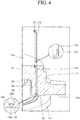
- FIG. 4 is a perspective view illustrating a high vacuum preventing device of FIG. 3
- FIG. 5 is an enlarged vertical sectional view illustrating a portion "A" in FIG. 3
- FIG. 6 is an enlarged vertical sectional view illustrating a portion where a first hole and a second hole are connected in FIG. 5
- FIG. 7 is a cross-sectional view taken along line IV-IV of FIG. 5 .
- an internal space 111 of a casing 110 may be divided into a suction space 112 as a low pressure part and a discharge space 113 as a high pressure part by a high/low pressure separation plate 114.
- a suction pipe 115 may be coupled to the suction space 112, and a discharge pipe 116 may be coupled to the discharge pipe 116.
- a central portion of the high/low pressure separation plate 114 is coupled to an upper surface of a non-orbiting scroll 140 (to be described hereinafter) and an outer circumferential surface thereof is airtightly coupled to an inner circumferential surface of the casing 110 to divide the internal space 111 of the casing 110 into the suction space 112 and the discharge space 113.
- a discharge plenum having a separate discharge space may be coupled to the non-orbiting scroll to divide the internal space of the casing into a suction space and a discharge space.
- a driving motor 120 generating a rotational force is installed in the suction space 112 of the casing 110, and a main frame 130 may be fixedly installed above the driving motor 120.
- a non-orbiting scroll 140 is installed on an upper surface of the min frame 130, and an orbiting scroll 150 may be installed to perform orbiting between the main frame 130 and the non-orbiting scroll 140.
- the orbiting scroll 150 is eccentrically coupled to a rotational shaft coupled to a rotor 122 of the driving motor 120, and the orbiting scroll 150, while performing an orbiting motion, forms a pair of two compression chambers P including a suction chamber P1, an intermediate pressure chamber P2, and a discharge chamber P3, together with the non-orbiting scroll 140.
- several intermediate pressure chambers may be continuously formed.
- first thrust bearing surface B1 may be formed between one surface of the main frame 130 and one surface of the orbiting scroll 140 corresponding thereto
- second thrust bearing surface B2 may be formed between the other surface of the orbiting scroll 150 and one surface of the non-orbiting scroll 140 corresponding thereto.
- a non-orbiting side hard plate part 141 is formed to have a disk shape, and a side wall part 142 supported by an upper surface of the main frame 130 may protrude in an annular shape from an edge of a lower surface of the non-orbiting side hard plate part 141.
- a non-orbiting wrap 143 may be formed in an involute type, a logarithmic spiral, or other shape to form the compression chamber P together with the orbiting wrap 152 of the orbiting scroll 150.
- a suction opening 144 may be formed on one side of the side wall part 142 in a penetrating manner such that the suction space 112 of the casing 110 communicates with the compression chamber P.
- the suction opening 144 may have a circular shape or a long hole shape and communicate with the suction chamber P1.
- a lower surface of the side wall part 142 is in contact with an edge of the orbiting side hard plate part 152 to form the second thrust surface (i.e., a sealing surface) B2.
- a frictional contact avoiding surface 142a may be formed to be lower than the second thrust surface on an outer surface of the lower surface of the side wall part 142, excluding the second thrust surface B2.
- a second hole 148b of a communication hole 148 should be formed on the second thrust surface B2 in order to restrain leakage of a refrigerant of the discharge space 113 to the suction space 112 during a normal operation.
- a discharge opening 145 may be formed at the center of the non-orbiting side hard plate part 141 such that the compression chamber P and the discharge space 113 of the casing 110 communicate with each other.
- a check valve 146 preventing a refrigerant discharged to the discharge space 113 from flowing backwards to the discharge opening 145 is installed on a side surface 141a adjacent to the discharge space of the non-orbiting scroll 140.
- a bypass hole 141b previously bypassing a portion of a refrigerant compressed in the compression chamber P may be formed in the vicinity of the check valve 146, and a bypass valve 147 opening and closing the bypass hole 141 may be installed in the vicinity of the bypass hole 141b.
- the check valve 146 or the bypass valve 147 may be formed as a reed valve shape in a cantilever form, and may be fixedly coupled to the non-orbiting scroll 140 using bolts 146b and 147b together with retainers 146a and 147a.
- an end of a decompression member 170 (to be described hereinafter) adjacent to the discharge space may be supported with respect to an axial direction by adjusting a length of the retainers 146a and 147a or a fastening position of the bolts 146b and 147b.
- the orbiting side hard plate part 151 of the orbiting scroll 150 supported by the main frame 130 has a disk shape
- an orbiting wrap 152 engaged with the non-orbiting wrap 143 to form the compression chamber P is formed on an upper surface of the orbiting side hard plate part 151
- a boss part 153 coupled to the rotational shaft 125 may b formed on a lower surface of the orbiting side hard plate part 151.
- the orbiting scroll 150 in a state of being eccentrically coupled to the rotational shaft 125, is engaged with the non-orbiting scroll 140 and makes an orbiting motion to form a pair of two compression chambers P each including a suction chamber P1, an intermediate pressure chamber P2, and a discharge chamber P3.
- the non-orbiting scroll 140 may be fixedly coupled to the main frame 130 or may be coupled to the main frame 130 so as to be movable in an axial direction according to circumstances.
- the non-orbiting scroll 140 in a case in which a back pressure chamber 134 is formed on a rear side of the orbiting scroll 150, the non-orbiting scroll 140 is fixed to the main frame 130, but in a case in which the back pressure chamber 140 is formed on a rear side of the non-orbiting scroll 140, the non-orbiting scroll 140 may be coupled to the main frame 130 so as to be movable in an axial direction.
- a plurality of sealing members 132 may be provided on the first thrust surface B1 to form the back pressure chamber 134 supporting the orbiting scroll 150, and a back pressure hole 155 guiding a refrigerant to the back pressure chamber 1334 of the intermediate pressure chamber P2 may be formed in the orbiting side hard plate part 151.
- Reference numeral 121 denotes a stator, and 160 denotes an oldham ring.
- a refrigerant is introduced to the suction space 112, a low pressure part, through the suction pipe 114 from a refrigerating cycle.
- the low pressure refrigerant introduced to the suction space 112 is introduced to the intermediate pressure chamber P2 through the suction opening 144 of the non-orbiting scroll 140 and the suction chamber P1, compressed, while moving to the center between the orbiting scroll 150 and the non-orbiting scroll 140 according to an orbiting motion of the orbiting scroll 150, and discharged to the discharge space 113 of the casing 110 from the discharging chamber P3 through the discharge opening 145 of the non-orbiting scroll 140, and the refrigerant is discharged to a refrigerating cycle through the discharge pipe 115.
- This sequential process is repeated.
- a portion of the refrigerant compressed in the compression chamber P is guided to the back pressure chamber 134 through the back pressure hole 155 from the intermediate pressure chamber P2, and the refrigerant guided to the back pressure chamber 134 supports the orbiting scroll 150 by a force based on the pressure such that the orbiting scroll 150 is tightly attached to the non-orbiting scroll 140 to seal the compression chamber P in an axial direction.
- a communication hole 148 may be formed to connect the discharge space 113 and the suction space 112 when pressure of the compression chamber P is lowered to a predetermined pressure or lower so the orbiting scroll 150 does not float.
- the communication hole 148 is formed to be too large, a behavior of the orbiting scroll 150 becomes unstable even during a normal operation or oil may be excessively introduced to the compression chamber P undesirably. If, however, the communication hole 148 is too small, it may be difficult to process the communication hole 148 to degrade productivity.
- the communication hole 148 is formed to be sufficiently large to be processed and the decompression member 170 is inserted within the communication hole 148 to reduce a radial sectional area of the communication hole 148 through which a refrigerant or oil passes, whereby refrigerant or oil is effectively decompressed. Accordingly, since the high pressure refrigerant is introduced to the suction space 112 as a low pressure part, the communication hole 148 is easily processed, while preventing degradation of efficiency of the compressor in advance, thereby enhancing productivity.
- the communication hole 148 may include a first hole 148a formed to have a predetermined depth from a side surface 141a of the discharge space side of the non-orbiting scroll 140 in an axial direction and a second hole 148b extending from the first hole 148a and penetrating through the second thrust surface B2.
- An inner diameter D1 of the first hole 148a may be greater than an inner diameter D2 of the second hole 148b.
- the communication hole 148 according to the present embodiment may be formed as a two-stage hole.
- the communication hole 148 may be formed as a multi-stage hole, in addition to the first hole 148a and the second hole 148b.
- an outer diameter of the decompression member 170 may be greater than the second hole 148b.
- a decompression effect may be further enhanced as a refrigerant passes through the communication hole having multiple stages.
- the communication hole 148 may also be formed as a single hole having the same inner diameter from a side surface 141a adjacent to the discharge space of the non-orbiting scroll 140 to the second thrust surface B2, but, in this case, however, it may be difficult for the communication hole 148 to be formed as a small hole having a size, i.e., from 1 to 2 mm, required for reducing pressure.
- the communication hole 148 may be formed to include the first hole 148a and the second hole 148b.
- connection surface 148c may be formed between the first hole 148a and the second hole 148b.
- connection surface 148c may be formed as a right angle surface between the first hole and the second hole.
- a diameter of the first hole 148a may be merely a few millimeters, and thus, it may be difficult to form the right angle surface through processing with a drill.
- connection surface 148c may be formed as a sloped surface as illustrated in FIG. 7 .
- the decompression member 170 may be mounted in the middle of the sloped surface.
- flow resistance between the first hole 148a and the second hole 148b may be reduced, and thus, a refrigerant may be rapidly moved.
- the second hole 148b may be covered by the decompression member 170.
- a communication recess 171 may be formed at one end of the decompression member 170, that is, at one end in contact with the connection surface 148c.
- the inner diameter D2 of the second small 148b is smaller than the diameter D3 of the decompression member 170 and the second hole 148b is covered by the decompression member 170, a refrigerant passing through the first hole 148a may smoothly flow to the second hole 148b through the communication hole 171.
- FIGS. 8A and 8B are vertical sectional views illustrating flow states of a refrigerant on the second thrust surface when the scroll compressor according to the present embodiment is normally operated or when the scroll compressor operates in a high vacuum state.
- the orbiting scroll 150 floats toward the non-orbiting scroll 140 by pressure of the back pressure chamber 134 and is tightly attached to the second thrust surface B2. Then, the second hole 148b of the communication hole 148 is closed and the refrigerant of the discharge space 113 is prevented from moving to the suction space 112.
- the refrigerant of the discharge space 113 has a discharge pressure, but the pressure is lowered as the refrigerant having the discharge pressure passes through a narrow passage 172 between an inner circumferential surface of the communication hole 148 and an outer circumferential surface of the decompression member 170.
- the refrigerant introduced to the suction space 112 is maintained at a significantly low pressure, compared with the discharge pressure, although the refrigerant is introduced to the compression chamber P, a suction loss may be minimized.
- one end of the decompression member 170 adjacent to the discharge space may be pressed by a support bolt 173 to fix the decompression member 170.
- the support bolt 173 may be fastened to the hard plate part 141 of the non-orbiting scroll 140 to thus support one end of the decompression member 170 may be supported by a head portion of the support bolt 173.
- one end of the decompression member 170 adjacent to the discharge side may be supported using an accessory of the check valve 146 preventing a back flow of the discharged refrigerant or a bypass valve 147 selectively bypassing the refrigerant at an intermediate pressure.
- the decompression member 170 may be supported using the head portion of the bolt 147b for fastening the bypass valve 147, or as illustrated in FIG. 9 , discharge side one end of the decompression member 170 may be supported by the retainer 147a by extending the retainer 147a limiting an opening amount of the bypass valve 147.
- the decompression member 170 may be press-fit and fixed to the communication hole 148 or a thread may be formed to be screw-fastened.
- At least one communication surface 174 having a D-cut shape may be formed on an outer circumferential surface of the decompression member 170 to form a passage 173 allowing a refrigerant to move between an inner circumferential surface of the communication hole 148 and the communication surface 174.
- the communication surface 174 may be formed as a linear surface or to have a spiral shape in a length direction between both ends of the outer circumferential surface of the decompression member 170 .
- the decompression member 170 may have a shape of a circular cross-section and the communication hole 148 may be formed to have an angular shape or a shape in which a plurality of circles partially overlap each other to form a passage 173 between the communication hole 148 and the decompression member 170. Accordingly, since a separate communication surface is not required to be formed on a surface of the decompression member 170, the decompression member 170 may be easily formed. Also, the communication hole 148 may have a circular shape and the decompression member 170 may have an angular shape.
- the decompression member 170 may not be fixed to the communication hole 148. In this case, since an outer diameter of the decompression member 170 is smaller than an inner diameter of the communication hole 148, the decompression member 170 may be moved by a pressure difference or vibration of the compressor within the communication hole 148, but a space between the decompression member 170 and the communication hole 148 is small and a portion of oil discharged to the discharge space 113 may be introduced to the passage 173 between the decompression member 170 and the communication hole 148 to restrain movement of the decompression member 170. However, when an abnormal condition occurs while the compressor is being transported or operated, the decompression member 170 may be released or cause noise of the compressor during an operation. Thus, preferably, the decompression member 170 is fixed to the communication hole 148 using the aforementioned embodiment, of the like.
- a decompression effect of the communication hole 148 may be defined by a relational expression regarding a length of the communication hole 148 and a radial sectional area of the passage 173. That is, the decompression effect may be enhanced as the communication hole 148 is longer and as the radial sectional area of the passage 173 is smaller.
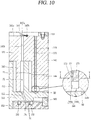
- a decompression effect for the same area may be higher when the passage 173 is formed on the entire outer circumferential surface of the decompression member 170 as illustrated in FIG. 5 than when the passage 173 is formed only on one side of the outer circumferential surface of the decompression member 170 as illustrated in FIG. 10 .
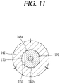
- the passage 173 is formed on one side of the outer circumferential surface of the decompression member 170 as illustrated in FIG. 11 , a vertical diameter is increased to reduce flow resistance to degrade a decompression effect, compared with the case in which the passage 173 is formed on the entire outer circumferential surface of the decompression member 170 as illustrated in FIG. 7 .
- the passage is formed to be evenly distributed along an outer circumferential surface of the decompression member.
- first hole 148a and the second hole 148b are formed to be concentric as described above, but according to circumstances, the first hole 148a and the second hole 148b may be formed to have different central axes.
- the first hole 148a may be formed at the center side of the non-orbiting scroll 140, relative to the second hole 148b and the second hole 148b may be positioned on an outer side and partially overlap a portion of the first hole 148a.
- the first hole (or a decompression member) 148a may be formed to have a length not to overlap the compression chamber P in a radial direction.
- the first hole 148a and the second hole 148b may be formed to have the same diameter, or the diameter D2 of the second hole 148b may be smaller than the diameter D1 of the first hole 148a.
- an overlap area between the first hole 148a and the second hole 148b is smaller than the inner diameter D1 of the first hole 148a, when the decompression member 170 is inserted into the first hole 148a, the second hole 148b may be covered.
- a communication recess may be formed at an end portion of the decompression member 170 and fixed to the connection surface 148c between the first hole 148a and the second hole 148b, or the communication surface 174 may be cut to have a D-cut shape on the outer circumferential surface of the decompression member 170 and press-fit to the first hole 148a as illustrated in FIG. 12 .
- the communication hole 148 in particular, the first hole 148a, may be formed to have a diameter sufficient to facilitate processing and an area of the communication hole 148 may be appropriately adjusted using the decompression member 170.
- the device provided between the discharge space as a high pressure part, and the suction space as a low pressure part to prevent a high vacuum state of a low pressure part is simplified, manufacturing cost may be reduced.
- a high vacuum state of the compression chamber may be rapidly released.
- the refrigerant introduced from the high pressure part to the low pressure part is decompressed to an appropriate pressure through the communication hole, generation of a suction loss at the low pressure part may be restrained to increase compressor efficiency.
- oil is contained in the refrigerant discharged from the compression chamber, but the refrigerant is separated from the oil in the discharge space 113 and discharged to the refrigeration cycle and the oil separated from the refrigerant remains in the discharge space 113.
- oil shortage occurs in the entire refrigeration cycle to degrade freezing capability, and oil shortage also occurs within the compressor, significantly degrading lubrication performance.
- the second hole 148b as an outlet of the communication hole 148 is preferably formed to be adjacent to the suction opening 144 or the suction chamber P1 in order to allow the refrigerant and oil introduced to the second thrust surface to be rapidly moved to the suction chamber P1.
- FIG. 13 is a bottom view of the non-orbiting scroll illustrating a position of the communication hole according to the present embodiment.
- the suction opening 144 is formed on one surface of the non-orbiting scroll 140 in a penetrating manner, and an outer compression pocket is not formed, starting from the suction opening 144 to a predetermined crank angle (substantially, 180° with respect to a central line L1 of the suction opening).
- a lower surface of the non-orbiting scroll 140 to this point does not form a thrust bearing surface (second thrust surface) and an abrasion avoiding surface (the shaded portion) 142a is formed to be stepped.
- a crank angle ( ⁇ ) at which the second hole 148b of the communication hole 148 is formed may be formed substantially within 270° along a trace of the wrap with respect to the central line L1 of a portion where the second thrust surface B2, that is, the suction opening 144.
- the decompression member is inserted into the communication hole 148 to decompress the refrigerant or oil in the communication hole 148, but in this embodiment, an extending recess 149 is formed on a side surface 141a of the non-orbiting scroll 140 adjacent to the discharge space to reduce a pressure in the extending recess 149.
- the extending recess 149 may be formed to have a circular arc shape on the side surface 141a of the non-orbiting scroll 140 adjacent to the discharge space.
- one end of the extending recess 149 may be connected to the communication hole 148 and the other end may be separated from the communication hole 148.
- a cover member 149a covering the extending recess 149 may be coupled to the side surface 141a of the non-orbiting scroll 140 adjacent to the discharge space.
- the cover member 149a may cover a portion where the extending recess 149 and the communication hole 148 communicate with each other, but open the other end of the extending recess 149 to communicate with the discharge space 113 to allow the refrigerant to be introduced from the discharge space 113 to the extending recess.
- the extending recess 149 may also have an annular shape.
- an exposed end 149b may be formed such that at least any one side of the extending recess 149, excluding the portion communicating with the communication hole 148, communicates with the discharge space 113.
- a decompression member may be installed in the communication hole 148, but since pressure is reduced in the extending recess 149, the decompression member may not be required to be installed in the communication hole 148.
- the extending recess 149 is formed to be smaller than a radial sectional area of the communication hole 148, the communication hole 148 difficult to process has a relatively large radial sectional area to increase processibility, but although the extending recess 149 easy to process has a small radial sectional area, processibility may be enhanced.
Landscapes
- Engineering & Computer Science (AREA)
- Mechanical Engineering (AREA)
- General Engineering & Computer Science (AREA)
- Physics & Mathematics (AREA)
- Fluid Mechanics (AREA)
- Rotary Pumps (AREA)
- Applications Or Details Of Rotary Compressors (AREA)
Abstract
Description
- The present disclosure relates to a scroll compressor, and particularly, to a scroll compressor having a high vacuum preventing device.
- A scroll compressor is a compressor in which a non-orbiting scroll is installed in an internal space of a casing and an orbiting scroll is engaged with the non-orbiting scroll to make an orbiting motion to form a pair of two compression chambers each including a suction chamber, an intermediate pressure chamber, and a discharge chamber between an non-orbiting wrap of the non-orbiting scroll and an orbiting wrap of the orbiting scroll.
- Scroll compressors, which smoothly performs sucking, compressing, and discharging operations on a refrigerant to obtain stable torque, while obtaining a high compression ratio, compared to other types of compressor, have been widely used for compressing a refrigerant in air-conditioning devices, and the like.
- Scroll compressors may be classified as a low pressure type scroll compressor and a high pressure type scroll compressor depending on how a refrigerant is supplied to a compression chamber. In the low pressure type scroll compressor, a refrigerant is indirectly sucked to a suction chamber through an internal space of a casing, and the internal space of the casing is divided into a suction space and a discharge space.
- In contrast, in the high pressure type scroll compressor, a refrigerant is directly sucked to a suction chamber, without passing through an internal space of a casing, and discharges through the internal space of the casing. In this scroll compressor, most of the internal space of the casing forms a discharge space.
- Also, the scroll compressor may be classified as a tip seal type scroll compressor and a back pressure type scroll compressor depending on a sealing scheme of a compression chamber. In the tip seal type scroll compressor, a tip seal is installed on a front end of a wrap of each scroll, and when the compressor is operated, the tip seal floats to be tightly attached to a disk plate part of an opposing scroll. Meanwhile, in the back pressure type scroll compressor, a back pressure chamber is formed on a rear side of one scroll, oil or a refrigerant at an intermediate pressure is induced to the back pressure chamber to cause the scroll to be pressed by pressure of the back pressure chamber so as to be tightly attached to the opposing scroll. In general, the tip seal scheme is applied to the low pressure type scroll compressor, while the back pressure scheme is applied to the high pressure type scroll compressor. However, recently, an example in which the back pressure scheme is applied to the low pressure type scroll compressor has been introduced.
-
FIG. 1 is a vertical sectional view illustrating an example of a related art low pressure and back pressure type scroll compressor. - As illustrated, in the related art scroll compressor, a
driving motor 20 generating a rotational force in aninternal space 11 of anairtight casing 10, and amain frame 30 is installed above the drivingmotor 20. - A
non-orbiting scroll 40 is fixedly installed on an upper surface of themain frame 30 and an orbitingscroll 50 is installed to be rotatable with respect to thenon-orbiting scroll 40 between themain frame 30 and thenon-orbiting scroll 40. The orbitingscroll 50 is eccentrically coupled to arotational shaft 25 coupled to arotor 22 of the drivingmotor 20. - In the
non-orbiting scroll 40, a fixed sidehard plate part 41 is formed to have a disk shape, and aside wall part 42 protruding from an edge of the fixed sidehard plate part 41, coupled to themain frame 30, and having an annular shape, and anon-orbiting wrap 43 forming a compression chamber P together with the orbiting wrap 52 (to be described hereinafter) is formed on an inner side of theside wall part 42. - A
suction opening 44 is formed on one side of theside wall part 42, and adischarge opening 45 is formed in a vicinity of the center of the fixed sidehard plate part 41. A lower surface of theside wall part 42 forms a second thrust bearing surface (hereinafter, referred to as a "second thrust surface") B2 together with an upper surface of the orbiting sidehard plate part 51. - In the orbiting
scroll 50, an orbiting sidehard plate part 51 supported by themain frame 30 has a disk shape, and the orbitingwrap 52 engaged with thenon-orbiting wrap 43 of thenon-orbiting scroll 40 to form the compression chamber P is formed on an upper surface of the orbiting sidehard plate part 51. - A
boss part 53 eccentrically coupled with therotational shaft 25 is formed at the center of a lower surface of the orbiting sidehard plate part 51. An outer lower surface of theboss part 53 is supported by an upper surface of themain frame 30 to form a first thrust bearing surface (hereinafter, referred to as a first thrust surface) B1 together with the upper surface of themain frame 30. - A back pressure chamber C is formed on the first thrust surface B1 between the orbiting
scroll 50 and themain frame 30, and aback pressure hole 55 guiding a refrigerant at an intermediate pressure, a pressure between a suction pressure and a discharge pressure, from the intermediate pressure chamber of the compression chamber P to the back pressure chamber C, is formed in the orbiting sidehard plate part 51. - Meanwhile, a low
pressure separation plate 14 separating theinternal space 11 of thecasing 10 into asuction space 12, a low pressure part, and adischarge space 13, a high pressure part, is coupled to an upper surface of themain frame 30. Asuction pipe 15 is coupled to thesuction space 12 and adischarge pipe 16 is coupled to thedischarge space 13, in a communicating manner. -
Reference numeral 21 denotes a stator, 26 denotes a subframe, and 60 denotes an oldam ring. - In the related art scroll compressor as described above, when power is applied to the driving
motor 20 to generate a rotational force, therotational shaft 25 transfers the rotational force from the drivingmotor 20 to theorbiting scroll 50. - Then, the orbiting
scroll 50 performs an orbiting motion with respect to thenon-orbiting scroll 40 by theoldam ring 60, forming a pair of two compression chambers P between theorbiting scroll 50 and thenon-orbiting scroll 40 to suck, compress, and discharge a refrigerant. - Here, a portion of the refrigerant compressed in the compression chamber P moves from the intermediate pressure chamber to the back pressure chamber C through the
back pressure hole 55, and the refrigerant at an intermediate pressure introduced to the back pressure chamber C generates a back pressure to cause the orbitingscroll 50 to float in a direction toward thenon-orbiting scroll 40 to seal the second thrust surface B2 between the orbitingscroll 50 and thenon-orbiting scroll 40. - Meanwhile, during an operation of the compressor, an amount of refrigerant sucked to the compression chamber P may be reduced as the suction side is blocked or for other reasons. In this case, pressure of the compression chamber P of the compressor may be lowered to put the compressor in a high vacuum state.
- When the compressor continuously operates in the high vacuum state, compression efficiency is lowered and the motor may be damaged. In consideration of this, in the related art, a high vacuum preventing device is provided within the compressor to bypass a portion of a refrigerant discharged to the discharge space to the suction space to resolve the high vacuum state.
- As the related art high vacuum preventing device, a scheme of using a valve is largely known.
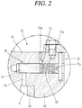
FIGS. 1 and2 illustrate an example of a scroll compressor having a high vacuum preventing device using a valve. - As illustrated, in the related art high
vacuum preventing device 70, acommunication flow channel 71 connecting the high pressure part and the low pressure part of thecasing 10 is formed in thenon-orbiting scroll 40, and avalve 72 for selectively opening and closing thecommunication flow channel 71 is installed in the middle of thecommunication flow channel 71 and supported by aspring 73. One end of thecommunication flow channel 71 is connected to the intermediate pressure chamber by anintermediate pressure hole 74, and thus, thevalve 72 is configured to open and close thecommunication flow channel 71, while moving according to a difference between a pressure of the intermediate pressure chamber and a spring force of thespring 73.Reference numeral 71a denotes a valve recess, 71b denotes a high pressure side flow channel, and 71c denotes a low pressure side flow channel. - Accordingly, when the compressor performs a normal operation, a pressure of the intermediate pressure chamber is so high that the
valve 72 surpasses thespring 73 and moves to the right side of the drawing to block between the high pressureside flow channel 71b and the low pressureside flow channel 71c. - Meanwhile, when the compressor is operated in a high vacuum state, an intermediate pressure introduced to the
valve recess 71a is so low that thevalve 72 is moved to an opening direction (left side of the drawing) by thespring 73, and accordingly, the highpressure flow channel 71b and the lowpressure flow channel 71c are connected to cause a high pressure refrigerant discharged to thedischarge space 13 to be sucked to the compression chamber P through thesuction space 12, thus temporarily resolve the high vacuum state. - However, the scroll compressor having the related art high vacuum preventing device as described above has a large number of components for constituting the high vacuum preventing device, and thus, the number of assembly processes to increase manufacturing cost.
- Also, the related art high vacuum preventing device has a configuration in which the
valve 72 moves according to a pressure difference to open or close thecommunication flow channel 71, and thus, a time is required for opening and closing thecommunication flow channel 71 and resolving the high vacuum state of the compression chamber is delayed. - In addition, in related art high vacuum preventing device, when a diameter of the
communication flow channel 71 is large in consideration of processiblity, a high pressure refrigerant of thedischarge space 13 is introduced to thesuction space 12 through thecommunication flow channel 71, making suction loss in thesuction space 12. Also, while the compressor is normally operated, a high pressure refrigerant introduced through thecommunication flow channel 71 pushes the orbitingscroll 50 to make a behavior of the orbitingscroll 50 unstable to cause the second thrust surface B2 to be open and leak the refrigerant, further lowering compression efficiency. - In addition, in the related art high vacuum preventing device, in a case in which a diameter of the
communication flow channel 71 is reduced to lower pressure of the refrigerant introduced from the discharge space to the suction space, it is difficult to process thecommunication flow channel 71. Also, as a foreign object is trapped to block thecommunication flow channel 71, thecommunication flow channel 71 may not function properly. - Therefore, an aspect of the detailed description is to provide a scroll compressor in which a device provided between a high pressure part and a low pressure part to prevent a high vacuum state of the lower pressure part is simplified to reduce manufacturing cost.
- Another aspect of the detailed description is to provide a scroll compressor in which a high vacuum preventing device is provided between a high pressure part and a low pressure part so that a refrigerant is rapidly moved from the high pressure part to the low pressure part.
- Another aspect of the detailed description is to provide a scroll compressor in which a refrigerant introduced from a high pressure part to a low pressure part is decompressed to an appropriate pressure and introduced to the low pressure part, thereby reducing suction loss of the compressor to increase compression efficiency.
- Another aspect of the detailed description is to provide a scroll compressor in which a flow channel guiding a refrigerant from a high pressure part to a low pressure part is formed to have a size that can be easily processed, while preventing a foreign object from being trapped.
- Another aspect of the detailed description is to provide a scroll compressor in which a flow channel guiding a refrigerant from a high pressure part to a low pressure part is formed to have a size that can be easily processed, while a refrigerant of the high pressure part is decompressed to be guided to the low pressure part.
- To achieve these and other advantages and in accordance with the purpose of this specification, as embodied and broadly described herein, a scroll compressor may include: a casing in which an internal space is divided into a suction space and a discharge space; a main frame coupled to the casing; a non-orbiting scroll coupled to the main frame and having a discharge space side surface included in the discharge space (or having a surface forming the discharge space); an orbiting scroll supported by the main frame in a thrust direction and having one surface forming a first thrust bearing surface together with the main frame and the other surface forming a second thrust bearing surface together with the non-orbiting scroll, and engaged with the non-orbiting scroll to form a compression chamber; a communication hole formed to penetrate from the discharge space side surface of the non-orbiting scroll to the second thrust bearing surface; and a decompression member inserted into the communication hole.
- A radial sectional area of the decompression member may be smaller than a sectional area of the communication hole in a radial direction to form a passage between an outer circumferential surface of the decompression member and an inner circumferential surface of the communication hole.
- The decompression member may have a communication recess formed at one end adjacent to the second thrust bearing surface.
- At least one communication surface may be formed on an outer circumferential surface of the decompression member between both ends of the decompression member.
- The communication hole may include: a first hole having a first inner diameter from the discharge space side surface to a predetermined depth; and a second hole communicating with the first hole, penetrating up to the second thrust bearing surface, and having a second inner diameter, wherein an inner diameter of the second hole is smaller than an outer diameter of the decompression member.
- An inner diameter of the first hole may be larger than an inner diameter of the second hole to form a connection surface between the first hole and the second hole, and one end of the decompression member may be supported by the connection surface.
- The decompression member may have a communication recess formed at an end portion in contact with the connection surface to allow the first hole and the second hole to communicate with each other.
- The decompression member may be formed to be smaller than the inner diameter of the communication hole, and a discharge space side end portion of the decompression member may be supported by a member provided on the discharge space side surface of the non-orbiting scroll in an axial direction.
- A valve may be installed on the discharge space side surface of the non-orbiting scroll, and at least a portion of the valve or a member supporting the valve may be installed to overlap a discharge space side end of the decompression member in an axial direction.
- A portion of an outer circumferential surface of the decompression member may be tightly attached and fixed to an inner circumferential surface of the communication hole, and a communication surface may be formed at least one of the inner circumferential surface of the communication hole and the outer circumferential surface of the decompression member to separate a portion of the inner circumferential surface of the communication hole and a portion of the outer circumferential surface of the decompression member.
- The decompression member may be formed to have a length such that at least a portion thereof overlaps the compression chamber in a radial direction.
- The decompression member may be positioned on an outer side with respect to the compression chamber in an axial direction.
- The first hole and the second hole may be formed such that central lines thereof in an axial direction are different.
- One end of the communication hole formed on the second thrust bearing surface may be formed on an outer side, relative to an outermost compression chamber.
- An extending recess communicating with the communication hole may be formed on a high pressure part side surface of the non-orbiting scroll and have a predetermined length, and a cover member covering a portion of the extending recess including a portion where the extending recess and the communication hole are connected may be coupled to the high pressure part side surface of the non-orbiting scroll.
- To achieve these and other advantages and in accordance with the purpose of this specification, as embodied and broadly described herein, a scroll compressor may include: a casing in which an internal space is divided into a suction space and a discharge space; a main frame coupled to the casing; a non-orbiting scroll coupled to the main frame and having a discharge space side surface included in the discharge space; an orbiting scroll supported by the main frame in a thrust direction and having one surface forming a first thrust bearing surface together with the main frame and the other surface forming a second thrust bearing surface together with the non-orbiting scroll, and engaged with the non-orbiting scroll to form a compression chamber; a communication hole formed to penetrate from the discharge space side surface of the non-orbiting scroll to the second thrust bearing surface; an extending recess extending to have a predetermined length and sectional area on the discharge space side surface of the non-orbiting scroll to communicate with the communication hole; and a cover member covering a portion of the extending recess including a portion where the extending recess and the communication hole are connected.
- A radial sectional area of the extending recess may be smaller than or equal to a radial sectional area of the communication hole.
- As described above, in the scroll compressor according to the present disclosure, a communication hole is formed to penetrate from the discharge space side surface of the non-orbiting scroll to the thrust bearing surface between the non-orbiting scroll and the orbiting scroll, and the decompression member having a radial sectional area smaller than that of the communication hole is inserted into the communication hole, whereby when a pressure of the compression chamber is rapidly lowered, a refrigerant discharged to the discharge space is introduced to the suction space through the passage between the communication hole and the decompression member, thereby preventing a high vacuum state of the compression chamber. Also, since the configuration of the device for preventing a high vacuum state is simplified, manufacturing cost may be reduced, and when the compressor is operated in a high vacuum state, a refrigerant of the discharge space may be rapidly moved to the suction space to resolve the high vacuum state.
- Also, since the high pressure refrigerant discharged to the discharge space is decompressed to an appropriate pressure, while passing through a narrow passage between the communication hole and the decompression member, a suction loss in the suction space may be restrained.
- In addition, a pressure of the refrigerant applied to the orbiting scroll through the communication hole even during a normal operation is lowered to prevent an unstable behavior of the orbiting scroll, whereby leakage in the compression chamber in an axial direction may be restrained.
- Also, since the passage between the communication hole and the decompression member is formed to be large to lengthen a decompression flow channel, a foreign object is prevented from being trapped.
- Also, when a high vacuum state is caused during an operation of the compressor, the refrigerant of the discharge space is introduced to the compression chamber through the communication hole to prevent the high vacuum state, whereby when the compressor is stopped, the thrust bearing surface between the non-orbiting scroll and the orbiting scroll is opened and the refrigerant of the discharge space is moved to the suction space through the communication hole to equalize the pressure, and thus, a normal operation may be rapidly performed at the time of restarting, enhancing compressor performance.
- Further scope of applicability of the present application will become more apparent from the detailed description given hereinafter. However, it should be understood that the detailed description and specific examples, while indicating preferred embodiments of the invention, are given by way of illustration only, since various changes and modifications within the scope of the invention will become apparent to those skilled in the art from the detailed description.
- The accompanying drawings, which are included to provide a further understanding of the invention and are incorporated in and constitute a part of this specification, illustrate exemplary embodiments and together with the description serve to explain the principles of the invention.
- In the drawings:
-
FIG. 1 is a vertical sectional view illustrating an example of a low pressure and back pressure type related art scroll compressor. -
FIG.2 is a vertical sectional view illustrating a high vacuum preventing device using a valve in the scroll compressor ofFIG. 1 . -
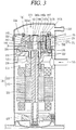
FIG. 3 is a vertical sectional view illustrating an example of a scroll compressor according to the present disclosure. -
FIG. 4 is a perspective view illustrating a high vacuum preventing device ofFIG. 3 . -
FIG. 5 is an enlarged vertical sectional view illustrating a portion "A" inFIG. 3 . -
FIG. 6 is an enlarged vertical sectional view illustrating a portion where a first hole and a second hole are connected inFIG. 5 . -
FIG. 7 is a cross-sectional view taken along line IV-IV ofFIG. 5 . -
FIGS. 8A and 8B are vertical sectional view illustrating a flow of a refrigerant when the scroll compressor ofFIG. 3 normally operates and when the scroll compressor abnormally operates. -
FIG. 9 is a vertical sectional view illustrating another embodiment of a method for fixing a decompression member in the high vacuum preventing device ofFIG. 3 . -
FIG. 10 is a vertical sectional view illustrating another embodiment of a decompression member in the high vacuum preventing device ofFIG. 3 . -
FIG. 11 is a cross-sectional view taken along line V-V ofFIG. 10 . -
FIG. 12 is a vertical sectional view illustrating another embodiment regarding a communication hole in the high vacuum preventing device ofFIG. 3 . -
FIG. 13 is a bottom view of a non-orbiting scroll to explain a through position of a communication hole in the high vacuum preventing device ofFIG. 3 . -
FIG. 14 is a perspective view illustrating another embodiment of a high vacuum preventing device of the present disclosure. -
FIG. 15 is a cross-sectional view taken along line VI-VI ofFIG. 14 . - Description will now be given in detail of the exemplary embodiments, with reference to the accompanying drawings. For the sake of brief description with reference to the drawings, the same or equivalent components will be provided with the same reference numbers, and description thereof will not be repeated.
- Hereinafter, a scroll compressor according to the present disclosure will be described in detail on the basis of embodiments illustrated in the accompanying drawings.
-
FIG. 3 is a vertical sectional view illustrating an example of a scroll compressor according to the present disclosure,FIG. 4 is a perspective view illustrating a high vacuum preventing device ofFIG. 3 ,FIG. 5 is an enlarged vertical sectional view illustrating a portion "A" inFIG. 3 ,FIG. 6 is an enlarged vertical sectional view illustrating a portion where a first hole and a second hole are connected inFIG. 5 , andFIG. 7 is a cross-sectional view taken along line IV-IV ofFIG. 5 . - As illustrated, in a scroll compressor according to the present embodiment, an
internal space 111 of a casing 110 may be divided into asuction space 112 as a low pressure part and adischarge space 113 as a high pressure part by a high/lowpressure separation plate 114. Asuction pipe 115 may be coupled to thesuction space 112, and adischarge pipe 116 may be coupled to thedischarge pipe 116. - A central portion of the high/low
pressure separation plate 114 is coupled to an upper surface of a non-orbiting scroll 140 (to be described hereinafter) and an outer circumferential surface thereof is airtightly coupled to an inner circumferential surface of the casing 110 to divide theinternal space 111 of the casing 110 into thesuction space 112 and thedischarge space 113. - Here, although not shown, a discharge plenum having a separate discharge space may be coupled to the non-orbiting scroll to divide the internal space of the casing into a suction space and a discharge space.
- A driving
motor 120 generating a rotational force is installed in thesuction space 112 of the casing 110, and amain frame 130 may be fixedly installed above the drivingmotor 120. - A
non-orbiting scroll 140 is installed on an upper surface of themin frame 130, and anorbiting scroll 150 may be installed to perform orbiting between themain frame 130 and thenon-orbiting scroll 140. - The
orbiting scroll 150 is eccentrically coupled to a rotational shaft coupled to arotor 122 of the drivingmotor 120, and theorbiting scroll 150, while performing an orbiting motion, forms a pair of two compression chambers P including a suction chamber P1, an intermediate pressure chamber P2, and a discharge chamber P3, together with thenon-orbiting scroll 140. Here, several intermediate pressure chambers may be continuously formed. - Here, a first thrust bearing surface (hereinafter, referred to as a "first thrust surface") B1 may be formed between one surface of the
main frame 130 and one surface of the orbiting scroll 140 corresponding thereto, and a second thrust bearing surface (hereinafter, referred to as a "second thrust surface") B2 may be formed between the other surface of theorbiting scroll 150 and one surface of thenon-orbiting scroll 140 corresponding thereto. - In the
non-orbiting scroll 140, a non-orbiting sidehard plate part 141 is formed to have a disk shape, and aside wall part 142 supported by an upper surface of themain frame 130 may protrude in an annular shape from an edge of a lower surface of the non-orbiting sidehard plate part 141. - A
non-orbiting wrap 143 may be formed in an involute type, a logarithmic spiral, or other shape to form the compression chamber P together with the orbiting wrap 152 of theorbiting scroll 150. - A
suction opening 144 may be formed on one side of theside wall part 142 in a penetrating manner such that thesuction space 112 of the casing 110 communicates with the compression chamber P. Thesuction opening 144 may have a circular shape or a long hole shape and communicate with the suction chamber P1. - A lower surface of the
side wall part 142 is in contact with an edge of the orbiting sidehard plate part 152 to form the second thrust surface (i.e., a sealing surface) B2. Also, a frictionalcontact avoiding surface 142a may be formed to be lower than the second thrust surface on an outer surface of the lower surface of theside wall part 142, excluding the second thrust surface B2. Thus, asecond hole 148b of a communication hole 148 (to be described hereinafter) should be formed on the second thrust surface B2 in order to restrain leakage of a refrigerant of thedischarge space 113 to thesuction space 112 during a normal operation. - A
discharge opening 145 may be formed at the center of the non-orbiting sidehard plate part 141 such that the compression chamber P and thedischarge space 113 of the casing 110 communicate with each other. - In the vicinity of the
discharge opening 145, acheck valve 146 preventing a refrigerant discharged to thedischarge space 113 from flowing backwards to thedischarge opening 145 is installed on aside surface 141a adjacent to the discharge space of thenon-orbiting scroll 140. Abypass hole 141b previously bypassing a portion of a refrigerant compressed in the compression chamber P may be formed in the vicinity of thecheck valve 146, and abypass valve 147 opening and closing thebypass hole 141 may be installed in the vicinity of thebypass hole 141b. - The
check valve 146 or thebypass valve 147 may be formed as a reed valve shape in a cantilever form, and may be fixedly coupled to thenon-orbiting scroll 140 usingbolts retainers retainers bolts - In the
orbiting stroll 150, the orbiting sidehard plate part 151 of theorbiting scroll 150 supported by themain frame 130 has a disk shape, anorbiting wrap 152 engaged with thenon-orbiting wrap 143 to form the compression chamber P is formed on an upper surface of the orbiting sidehard plate part 151, and aboss part 153 coupled to therotational shaft 125 may b formed on a lower surface of the orbiting sidehard plate part 151. Accordingly, theorbiting scroll 150, in a state of being eccentrically coupled to therotational shaft 125, is engaged with thenon-orbiting scroll 140 and makes an orbiting motion to form a pair of two compression chambers P each including a suction chamber P1, an intermediate pressure chamber P2, and a discharge chamber P3. - Meanwhile, the
non-orbiting scroll 140 may be fixedly coupled to themain frame 130 or may be coupled to themain frame 130 so as to be movable in an axial direction according to circumstances. For example, as illustrated inFIGS. 3 to 5 , in a case in which aback pressure chamber 134 is formed on a rear side of theorbiting scroll 150, thenon-orbiting scroll 140 is fixed to themain frame 130, but in a case in which theback pressure chamber 140 is formed on a rear side of thenon-orbiting scroll 140, thenon-orbiting scroll 140 may be coupled to themain frame 130 so as to be movable in an axial direction. - Here, when the
non-orbiting scroll 140 is fixed to themain frame 130, a plurality of sealingmembers 132 may be provided on the first thrust surface B1 to form theback pressure chamber 134 supporting theorbiting scroll 150, and aback pressure hole 155 guiding a refrigerant to the back pressure chamber 1334 of the intermediate pressure chamber P2 may be formed in the orbiting sidehard plate part 151. -
Reference numeral 121 denotes a stator, and 160 denotes an oldham ring. - In the scroll compressor according to the present embodiment as described above, a refrigerant is introduced to the
suction space 112, a low pressure part, through thesuction pipe 114 from a refrigerating cycle. The low pressure refrigerant introduced to thesuction space 112 is introduced to the intermediate pressure chamber P2 through thesuction opening 144 of thenon-orbiting scroll 140 and the suction chamber P1, compressed, while moving to the center between the orbitingscroll 150 and thenon-orbiting scroll 140 according to an orbiting motion of theorbiting scroll 150, and discharged to thedischarge space 113 of the casing 110 from the discharging chamber P3 through the discharge opening 145 of thenon-orbiting scroll 140, and the refrigerant is discharged to a refrigerating cycle through thedischarge pipe 115. This sequential process is repeated. - Here, a portion of the refrigerant compressed in the compression chamber P is guided to the
back pressure chamber 134 through theback pressure hole 155 from the intermediate pressure chamber P2, and the refrigerant guided to theback pressure chamber 134 supports theorbiting scroll 150 by a force based on the pressure such that theorbiting scroll 150 is tightly attached to thenon-orbiting scroll 140 to seal the compression chamber P in an axial direction. - However, when the refrigerating cycle has an error or when a pump-down operation is performed, an amount of the refrigerant sucked to the
suction space 112 of the compressor is significantly reduced to lower pressure of the compression chamber P or make the compressor be in a high vacuum state. When pressure of the compression chamber P is lowered to a predetermined pressure or lower or when the compression chamber is in a high vacuum state, pressure of theback pressure chamber 134 is lowered so the orbitingscroll 150 cannot float, and when theorbiting scroll 150 does not float, a space between thenon-orbiting scroll 140 and theorbiting scroll 150, that is, the second thrust surfaces B2, is open to further increase leakage in an axial direction to significantly lower compressor efficiency. - In consideration of this, a
communication hole 148 may be formed to connect thedischarge space 113 and thesuction space 112 when pressure of the compression chamber P is lowered to a predetermined pressure or lower so the orbitingscroll 150 does not float. - However, if the
communication hole 148 is formed to be too large, a behavior of theorbiting scroll 150 becomes unstable even during a normal operation or oil may be excessively introduced to the compression chamber P undesirably. If, however, thecommunication hole 148 is too small, it may be difficult to process thecommunication hole 148 to degrade productivity. - Thus, in the present embodiment, the
communication hole 148 is formed to be sufficiently large to be processed and thedecompression member 170 is inserted within thecommunication hole 148 to reduce a radial sectional area of thecommunication hole 148 through which a refrigerant or oil passes, whereby refrigerant or oil is effectively decompressed. Accordingly, since the high pressure refrigerant is introduced to thesuction space 112 as a low pressure part, thecommunication hole 148 is easily processed, while preventing degradation of efficiency of the compressor in advance, thereby enhancing productivity. - To this end, the
communication hole 148 according to the present disclosure may include afirst hole 148a formed to have a predetermined depth from aside surface 141a of the discharge space side of thenon-orbiting scroll 140 in an axial direction and asecond hole 148b extending from thefirst hole 148a and penetrating through the second thrust surface B2. - An inner diameter D1 of the
first hole 148a may be greater than an inner diameter D2 of thesecond hole 148b. Thus, thecommunication hole 148 according to the present embodiment may be formed as a two-stage hole. Although not shown, thecommunication hole 148 may be formed as a multi-stage hole, in addition to thefirst hole 148a and thesecond hole 148b. In this case, an outer diameter of thedecompression member 170 may be greater than thesecond hole 148b. Also, in this case, a decompression effect may be further enhanced as a refrigerant passes through the communication hole having multiple stages. - Here, the
communication hole 148 may also be formed as a single hole having the same inner diameter from aside surface 141a adjacent to the discharge space of thenon-orbiting scroll 140 to the second thrust surface B2, but, in this case, however, it may be difficult for thecommunication hole 148 to be formed as a small hole having a size, i.e., from 1 to 2 mm, required for reducing pressure. - Thus, as in the present embodiment, even though the
second hole 148b is formed to be short, thecommunication hole 148 may be formed to include thefirst hole 148a and thesecond hole 148b. - As mentioned above, since the inner diameter D1 of the
first hole 148a is formed to be greater than the inner diameter D2 of thesecond hole 148b, aconnection surface 148c may be formed between thefirst hole 148a and thesecond hole 148b. Thus, when a bar-shapeddecompression member 170 having a predetermined diameter is inserted into thefirst hole 148a, one end of thedecompression member 170 may be installed in theconnection surface 148c. - As illustrated in
FIG. 6 , theconnection surface 148c may be formed as a right angle surface between the first hole and the second hole. Here, however, a diameter of thefirst hole 148a may be merely a few millimeters, and thus, it may be difficult to form the right angle surface through processing with a drill. - Thus, the
connection surface 148c may be formed as a sloped surface as illustrated inFIG. 7 . When theconnection surface 148c is formed as a sloped surface, thedecompression member 170 may be mounted in the middle of the sloped surface. When theconnection surface 148c is formed as a sloped surface, flow resistance between thefirst hole 148a and thesecond hole 148b may be reduced, and thus, a refrigerant may be rapidly moved. - Meanwhile, when the decompression member is inserted into the
first hole 148a, thesecond hole 148b may be covered by thedecompression member 170. - A
communication recess 171 may be formed at one end of thedecompression member 170, that is, at one end in contact with theconnection surface 148c. Thus, although the inner diameter D2 of the second small 148b is smaller than the diameter D3 of thedecompression member 170 and thesecond hole 148b is covered by thedecompression member 170, a refrigerant passing through thefirst hole 148a may smoothly flow to thesecond hole 148b through thecommunication hole 171. -
FIGS. 8A and 8B are vertical sectional views illustrating flow states of a refrigerant on the second thrust surface when the scroll compressor according to the present embodiment is normally operated or when the scroll compressor operates in a high vacuum state. - As illustrated in
FIG. 8A , when the compressor is normally operated, theorbiting scroll 150 floats toward thenon-orbiting scroll 140 by pressure of theback pressure chamber 134 and is tightly attached to the second thrust surface B2. Then, thesecond hole 148b of thecommunication hole 148 is closed and the refrigerant of thedischarge space 113 is prevented from moving to thesuction space 112. - Meanwhile, as illustrated in
FIG. 8B , in a case in which the compressor is in an abnormal operation state in which a suction pressure of a refrigerant is lowered and a suction amount of the refrigerant is reduced, an intermediate pressure is lowered. Then, pressure of theback pressure chamber 134 is lowered, theorbiting scroll 150 does not float and is separated from thenon-orbiting scroll 140. Then, thesecond hole 148b of thecommunication hole 148 is opened and the refrigerant of thedischarge space 113 is moved to thesuction space 112. Then, the refrigerant moving to thesuction space 112 moves to the compression chamber P through thesuction opening 144, whereby the compression chamber P is restrained from being highly vacuumized. - Here, the refrigerant of the
discharge space 113 has a discharge pressure, but the pressure is lowered as the refrigerant having the discharge pressure passes through anarrow passage 172 between an inner circumferential surface of thecommunication hole 148 and an outer circumferential surface of thedecompression member 170. Thus, since the refrigerant introduced to thesuction space 112 is maintained at a significantly low pressure, compared with the discharge pressure, although the refrigerant is introduced to the compression chamber P, a suction loss may be minimized. - Meanwhile, in a state in which the
decompression member 170 is inserted into thecommunication hole 148, one end of thedecompression member 170 adjacent to the discharge space may be pressed by asupport bolt 173 to fix thedecompression member 170. As illustrated inFIG. 5 , thesupport bolt 173 may be fastened to thehard plate part 141 of thenon-orbiting scroll 140 to thus support one end of thedecompression member 170 may be supported by a head portion of thesupport bolt 173. - Also, one end of the
decompression member 170 adjacent to the discharge side may be supported using an accessory of thecheck valve 146 preventing a back flow of the discharged refrigerant or abypass valve 147 selectively bypassing the refrigerant at an intermediate pressure. - For example, the
decompression member 170 may be supported using the head portion of thebolt 147b for fastening thebypass valve 147, or as illustrated inFIG. 9 , discharge side one end of thedecompression member 170 may be supported by theretainer 147a by extending theretainer 147a limiting an opening amount of thebypass valve 147. - Alternatively, rather than being fixed using a separate member, the
decompression member 170 may be press-fit and fixed to thecommunication hole 148 or a thread may be formed to be screw-fastened. - Also, in this case, as illustrated in
FIGS. 10 and11 , at least onecommunication surface 174 having a D-cut shape may be formed on an outer circumferential surface of thedecompression member 170 to form apassage 173 allowing a refrigerant to move between an inner circumferential surface of thecommunication hole 148 and thecommunication surface 174. Thecommunication surface 174 may be formed as a linear surface or to have a spiral shape in a length direction between both ends of the outer circumferential surface of thedecompression member 170 . - Also, although not shown, the
decompression member 170 may have a shape of a circular cross-section and thecommunication hole 148 may be formed to have an angular shape or a shape in which a plurality of circles partially overlap each other to form apassage 173 between thecommunication hole 148 and thedecompression member 170. Accordingly, since a separate communication surface is not required to be formed on a surface of thedecompression member 170, thedecompression member 170 may be easily formed. Also, thecommunication hole 148 may have a circular shape and thedecompression member 170 may have an angular shape. - The
decompression member 170 may not be fixed to thecommunication hole 148. In this case, since an outer diameter of thedecompression member 170 is smaller than an inner diameter of thecommunication hole 148, thedecompression member 170 may be moved by a pressure difference or vibration of the compressor within thecommunication hole 148, but a space between thedecompression member 170 and thecommunication hole 148 is small and a portion of oil discharged to thedischarge space 113 may be introduced to thepassage 173 between thedecompression member 170 and thecommunication hole 148 to restrain movement of thedecompression member 170. However, when an abnormal condition occurs while the compressor is being transported or operated, thedecompression member 170 may be released or cause noise of the compressor during an operation. Thus, preferably, thedecompression member 170 is fixed to thecommunication hole 148 using the aforementioned embodiment, of the like. - Meanwhile, a decompression effect of the
communication hole 148 may be defined by a relational expression regarding a length of thecommunication hole 148 and a radial sectional area of thepassage 173. That is, the decompression effect may be enhanced as thecommunication hole 148 is longer and as the radial sectional area of thepassage 173 is smaller. - In particular, considering the decomposition effect, a decompression effect for the same area may be higher when the
passage 173 is formed on the entire outer circumferential surface of thedecompression member 170 as illustrated inFIG. 5 than when thepassage 173 is formed only on one side of the outer circumferential surface of thedecompression member 170 as illustrated inFIG. 10 . - That is, when the
passage 173 is formed on one side of the outer circumferential surface of thedecompression member 170 as illustrated inFIG. 11 , a vertical diameter is increased to reduce flow resistance to degrade a decompression effect, compared with the case in which thepassage 173 is formed on the entire outer circumferential surface of thedecompression member 170 as illustrated inFIG. 7 . Thus, when the area of the passage is the same, preferably, the passage is formed to be evenly distributed along an outer circumferential surface of the decompression member. - Another embodiment of the communication hole according to the present disclosure will be described.
- That is, the
first hole 148a and thesecond hole 148b are formed to be concentric as described above, but according to circumstances, thefirst hole 148a and thesecond hole 148b may be formed to have different central axes. - For example, as illustrated in
FIG. 12 , in a case in which an outer diameter of thehard plate part 141 of thenon-orbiting scroll 140 is positioned on an inner side than the outermostnon-orbiting wrap 143 or in a case in which there is not much space in an edge of at least the non-orbiting side hard plate part 141 (i.e., in a case in which a space for forming a communication hole is not sufficient), thefirst hole 148a may be formed at the center side of thenon-orbiting scroll 140, relative to thesecond hole 148b and thesecond hole 148b may be positioned on an outer side and partially overlap a portion of thefirst hole 148a. Thus, the first hole (or a decompression member) 148a may be formed to have a length not to overlap the compression chamber P in a radial direction. - Also, in this case, the
first hole 148a and thesecond hole 148b may be formed to have the same diameter, or the diameter D2 of thesecond hole 148b may be smaller than the diameter D1 of thefirst hole 148a. However, since an overlap area between thefirst hole 148a and thesecond hole 148b is smaller than the inner diameter D1 of thefirst hole 148a, when thedecompression member 170 is inserted into thefirst hole 148a, thesecond hole 148b may be covered. Thus, also, in this case, a communication recess may be formed at an end portion of thedecompression member 170 and fixed to theconnection surface 148c between thefirst hole 148a and thesecond hole 148b, or thecommunication surface 174 may be cut to have a D-cut shape on the outer circumferential surface of thedecompression member 170 and press-fit to thefirst hole 148a as illustrated inFIG. 12 . - Thus, the
communication hole 148, in particular, thefirst hole 148a, may be formed to have a diameter sufficient to facilitate processing and an area of thecommunication hole 148 may be appropriately adjusted using thedecompression member 170. - Accordingly, a phenomenon that a behavior of the orbiting scroll is unstable due to a refrigerant introduced to the communication hole to open the second thrust surfaces when the compressor performs a normal operation may be suppressed.
- Also, since the device provided between the discharge space as a high pressure part, and the suction space as a low pressure part to prevent a high vacuum state of a low pressure part is simplified, manufacturing cost may be reduced.
- Also, since the refrigerant is rapidly moved from the high pressure part to the low pressure part, a high vacuum state of the compression chamber may be rapidly released.
- Also, since the refrigerant introduced from the high pressure part to the low pressure part is decompressed to an appropriate pressure through the communication hole, generation of a suction loss at the low pressure part may be restrained to increase compressor efficiency.
- Also, oil is contained in the refrigerant discharged from the compression chamber, but the refrigerant is separated from the oil in the
discharge space 113 and discharged to the refrigeration cycle and the oil separated from the refrigerant remains in thedischarge space 113. When an amount of the remaining oil is increased, oil shortage occurs in the entire refrigeration cycle to degrade freezing capability, and oil shortage also occurs within the compressor, significantly degrading lubrication performance. - However, when the
communication hole 148 is formed as in the present embodiment, oil flows to the second thrust surface B2 through thecommunication hole 148 little by little, and in particular, when pressure of thesuction space 112 is rapidly lowered, oil is bypassed to thesuction space 112 together with the refrigerant to resolve oil shortage in the entire refrigeration cycle including the compressor. Also, in this case, oil may be decompressed, while passing through thepassage 173 between thenarrow communication hole 148 and the decompression member, thus restraining a suction loss. - Meanwhile, the
second hole 148b as an outlet of thecommunication hole 148 is preferably formed to be adjacent to thesuction opening 144 or the suction chamber P1 in order to allow the refrigerant and oil introduced to the second thrust surface to be rapidly moved to the suction chamber P1. -
FIG. 13 is a bottom view of the non-orbiting scroll illustrating a position of the communication hole according to the present embodiment. As illustrated, thesuction opening 144 is formed on one surface of thenon-orbiting scroll 140 in a penetrating manner, and an outer compression pocket is not formed, starting from thesuction opening 144 to a predetermined crank angle (substantially, 180° with respect to a central line L1 of the suction opening). Thus, a lower surface of thenon-orbiting scroll 140 to this point does not form a thrust bearing surface (second thrust surface) and an abrasion avoiding surface (the shaded portion) 142a is formed to be stepped. - Thus, a crank angle (α) at which the
second hole 148b of thecommunication hole 148 is formed may be formed substantially within 270° along a trace of the wrap with respect to the central line L1 of a portion where the second thrust surface B2, that is, thesuction opening 144. - Meanwhile, another embodiment of the scroll compressor according to the present disclosure will be described.
- That is, in the aforementioned embodiment, the decompression member is inserted into the
communication hole 148 to decompress the refrigerant or oil in thecommunication hole 148, but in this embodiment, an extendingrecess 149 is formed on aside surface 141a of thenon-orbiting scroll 140 adjacent to the discharge space to reduce a pressure in the extendingrecess 149. - For example, as illustrated in
FIGS. 14 and 15 , the extendingrecess 149 may be formed to have a circular arc shape on theside surface 141a of thenon-orbiting scroll 140 adjacent to the discharge space. Thus, one end of the extendingrecess 149 may be connected to thecommunication hole 148 and the other end may be separated from thecommunication hole 148. - A
cover member 149a covering the extendingrecess 149 may be coupled to theside surface 141a of thenon-orbiting scroll 140 adjacent to the discharge space. Here, thecover member 149a may cover a portion where the extendingrecess 149 and thecommunication hole 148 communicate with each other, but open the other end of the extendingrecess 149 to communicate with thedischarge space 113 to allow the refrigerant to be introduced from thedischarge space 113 to the extending recess. - The extending
recess 149 may also have an annular shape. In this case, anexposed end 149b may be formed such that at least any one side of the extendingrecess 149, excluding the portion communicating with thecommunication hole 148, communicates with thedischarge space 113. - A basic configuration and operational effect of the scroll compressor according to the present embodiment described above are the same as those of the previous embodiment. However, in the present embodiment, a decompression member may be installed in the
communication hole 148, but since pressure is reduced in the extendingrecess 149, the decompression member may not be required to be installed in thecommunication hole 148. - Also, in the present embodiment, since the extending
recess 149 is formed to be smaller than a radial sectional area of thecommunication hole 148, thecommunication hole 148 difficult to process has a relatively large radial sectional area to increase processibility, but although the extendingrecess 149 easy to process has a small radial sectional area, processibility may be enhanced. - The foregoing embodiments and advantages are merely exemplary and are not to be considered as limiting the present disclosure. The present teachings can be readily applied to other types of apparatuses. This description is intended to be illustrative, and not to limit the scope of the claims. Many alternatives, modifications, and variations will be apparent to those skilled in the art. The features, structures, methods, and other characteristics of the exemplary embodiments described herein may be combined in various ways to obtain additional and/or alternative exemplary embodiments.
- As the present features may be embodied in several forms without departing from the characteristics thereof, it should also be understood that the above-described embodiments are not limited by any of the details of the foregoing description, unless otherwise specified, but rather should be considered broadly within its scope as defined in the appended claims, and therefore all changes and modifications that fall within the metes and bounds of the claims, or equivalents of such metes and bounds are therefore intended to be embraced by the appended claims.
Claims (17)
- A scroll compressor comprising:a casing in which an internal space is divided into a suction space and a discharge space;a main frame coupled to the casing;a non-orbiting scroll coupled to the main frame and having a discharge space side surface included in the discharge space;an orbiting scroll supported by the main frame in a thrust direction and having one surface forming a first thrust bearing surface together with the main frame and the other surface forming a second thrust bearing surface together with the non-orbiting scroll, and engaged with the non-orbiting scroll to form a compression chamber;a communication hole formed to penetrate from the discharge space side surface of the non-orbiting scroll to the second thrust bearing surface; anda decompression member inserted into the communication hole.
- The scroll compressor of claim 1, wherein a radial sectional area of the decompression member is smaller than a sectional area of the communication hole in a radial direction to form a passage between an outer circumferential surface of the decompression member and an inner circumferential surface of the communication hole.
- The scroll compressor of claim 1, wherein the decompression member has a communication recess formed at one end adjacent to the second thrust
bearing surface. - The scroll compressor of claim 1, wherein at least one communication surface is formed on an outer circumferential surface of the decompression member between both ends of the decompression member.
- The scroll compressor of claim 1, wherein the communication hole includes:a first hole having a first inner diameter from the discharge space side surface to a predetermined depth; anda second hole communicating with the first hole, penetrating up to the second thrust bearing surface, and having a second inner diameter,wherein an inner diameter of the second hole is smaller than an outer diameter of the decompression member.
- The scroll compressor of claim 5, wherein an inner diameter of the first hole is larger than an inner diameter of the second hole to form a connection surface between the first hole and the second hole, and one end of the decompression member is supported by the connection surface.
- The scroll compressor of claim 6, wherein the decompression member has a communication recess formed at an end portion in contact with the connection surface to allow the first hole and the second hole to communicate with each other.
- The scroll compressor of claim 1, wherein the decompression member is formed to be smaller than the inner diameter of the communication hole, and a discharge space side end portion of the decompression member is supported by a member provided on the discharge space side surface of the non-orbiting scroll in an axial direction.
- The scroll compressor of claim 8, wherein a valve is installed on the discharge space side surface of the non-orbiting scroll, and at least a portion of the valve or a member supporting the valve is installed to overlap a discharge space side end of the decompression member in an axial direction.
- The scroll compressor of claim 1, wherein
a portion of an outer circumferential surface of the decompression member is tightly attached and fixed to an inner circumferential surface of the communication hole, and
a communication surface is formed at least one of the inner circumferential surface of the communication hole and the outer circumferential surface of the decompression member to separate a portion of the inner circumferential surface of the communication hole and a portion of the outer circumferential surface of the decompression member. - The scroll compressor of claim 1, wherein the decompression member is formed to have a length such that at least a portion thereof overlaps the compression chamber in a radial direction.
- The scroll compressor of claim 1, wherein the decompression member is positioned on an outer side with respect to the compression chamber in an axial direction.
- The scroll compressor of claim 12, wherein the first hole and the second hole are formed such that central lines thereof in an axial direction are different.
- The scroll compressor of claim 1, wherein one end of the communication hole formed on the second thrust bearing surface is formed on an outer side, relative to an outermost compression chamber.
- The scroll compressor of claim 1, wherein
an extending recess communicating with the communication hole is formed on a high pressure part side surface of the non-orbiting scroll and has a predetermined length, and
a cover member covering a portion of the extending recess including a portion where the extending recess and the communication hole are connected is coupled to the high pressure part side surface of the non-orbiting scroll. - A scroll compressor comprising:a casing in which an internal space is divided into a suction space and a discharge space;a main frame coupled to the casing;a non-orbiting scroll coupled to the main frame and having a discharge space side surface included in the discharge space;an orbiting scroll supported by the main frame in a thrust direction and having one surface forming a first thrust bearing surface together with the main frame and the other surface forming a second thrust bearing surface together with the non-orbiting scroll, and engaged with the non-orbiting scroll to form a compression chamber;a communication hole formed to penetrate from the discharge space side surface of the non-orbiting scroll to the second thrust bearing surface;an extending recess extending to have a predetermined length and sectional area on the discharge space side surface of the non-orbiting scroll to communicate with the communication hole; anda cover member covering a portion of the extending recess including a portion where the extending recess and the communication hole are connected.
- The scroll compressor of claim 16, wherein a radial sectional area of the extending recess is smaller than or equal to a radial sectional area of the communication hole.
Applications Claiming Priority (2)
| Application Number | Priority Date | Filing Date | Title |
|---|---|---|---|
| KR1020150175224A KR101731449B1 (en) | 2015-12-09 | 2015-12-09 | Scroll compressor |
| PCT/KR2016/013206 WO2017099384A1 (en) | 2015-12-09 | 2016-11-16 | Scroll compressor |
Publications (3)
| Publication Number | Publication Date |
|---|---|
| EP3388672A1 true EP3388672A1 (en) | 2018-10-17 |
| EP3388672A4 EP3388672A4 (en) | 2019-08-07 |
| EP3388672B1 EP3388672B1 (en) | 2020-05-06 |
Family
ID=58702273
Family Applications (1)
| Application Number | Title | Priority Date | Filing Date |
|---|---|---|---|
| EP16873250.1A Active EP3388672B1 (en) | 2015-12-09 | 2016-11-16 | Scroll compressor |
Country Status (4)
| Country | Link |
|---|---|
| US (1) | US10527039B2 (en) |
| EP (1) | EP3388672B1 (en) |
| KR (1) | KR101731449B1 (en) |
| WO (1) | WO2017099384A1 (en) |
Families Citing this family (1)
| Publication number | Priority date | Publication date | Assignee | Title |
|---|---|---|---|---|
| KR102317527B1 (en) * | 2017-06-15 | 2021-10-26 | 엘지전자 주식회사 | Scroll compressor |
Family Cites Families (11)
| Publication number | Priority date | Publication date | Assignee | Title |
|---|---|---|---|---|
| US6341945B1 (en) * | 1999-10-18 | 2002-01-29 | Scroll Technologies | Scroll compressor with reduced capacity at high operating temperatures |
| JP2003232286A (en) * | 2002-02-12 | 2003-08-22 | Sanden Corp | Scroll type compressor |
| JP2006097495A (en) * | 2004-09-28 | 2006-04-13 | Sanden Corp | Compressor |
| JP2007032511A (en) * | 2005-07-29 | 2007-02-08 | Sanden Corp | Pressure reducing device for fluid machine, and fluid machine and refrigerating circuit using the same |
| JP2010101188A (en) | 2008-10-21 | 2010-05-06 | Daikin Ind Ltd | Scroll compressor |
| JP2010106730A (en) * | 2008-10-29 | 2010-05-13 | Sanden Corp | Scroll compressor with built-in oil separator |
| KR101510699B1 (en) * | 2009-01-07 | 2015-04-17 | 엘지전자 주식회사 | Scoroll compressor and refrigerator having the same |
| JP2010163877A (en) | 2009-01-13 | 2010-07-29 | Daikin Ind Ltd | Rotary compressor |
| JP5550419B2 (en) * | 2010-03-31 | 2014-07-16 | 三菱重工業株式会社 | Compressor |
| CN103384769B (en) * | 2011-03-29 | 2015-10-07 | 日立空调·家用电器株式会社 | Scroll compressor |
| KR101300261B1 (en) | 2011-11-09 | 2013-08-23 | 엘지전자 주식회사 | Scroll compressor |
-
2015
- 2015-12-09 KR KR1020150175224A patent/KR101731449B1/en active IP Right Grant
-
2016
- 2016-11-16 EP EP16873250.1A patent/EP3388672B1/en active Active
- 2016-11-16 WO PCT/KR2016/013206 patent/WO2017099384A1/en active Application Filing
- 2016-12-08 US US15/372,762 patent/US10527039B2/en active Active
Also Published As
| Publication number | Publication date |
|---|---|
| US10527039B2 (en) | 2020-01-07 |
| KR101731449B1 (en) | 2017-04-28 |
| US20170167485A1 (en) | 2017-06-15 |
| WO2017099384A1 (en) | 2017-06-15 |
| EP3388672A4 (en) | 2019-08-07 |
| EP3388672B1 (en) | 2020-05-06 |
Similar Documents
| Publication | Publication Date | Title |
|---|---|---|
| US9145891B2 (en) | Scroll compressor | |
| US9541083B2 (en) | Scroll compressor including communication hole with improved back pressure chamber and back pressure hole locations | |
| WO2016136185A1 (en) | Scroll-type compressor | |
| US11193476B2 (en) | Scroll compressor | |
| US7204680B2 (en) | Oil supply device of scroll compressor | |
| US20090060767A1 (en) | Axial compliance | |
| US11703052B2 (en) | High pressure scroll compressor | |
| KR102060475B1 (en) | Motor operated compressor | |
| KR101800512B1 (en) | Motor-driven compressor | |
| EP3388672B1 (en) | Scroll compressor | |
| KR101909606B1 (en) | Scroll compressor | |
| US9188126B2 (en) | Hermatic compressor having a fluid guide disposed in an intermediate chamber | |
| US11022121B2 (en) | Scroll compressor | |
| US8876503B2 (en) | Scroll compressor with shaft inserting portion and manufacturing method thereof | |
| EP2685106B1 (en) | Two-stage compressor and two-stage compression system | |
| JP6779712B2 (en) | Scroll compressor | |
| JP2010156249A (en) | Scroll compressor | |
| JP6760804B2 (en) | Compressor | |
| JP5180698B2 (en) | Scroll type fluid machinery | |
| KR100834017B1 (en) | Bypass apparatus for scroll compressor | |
| JP4598695B2 (en) | Compressor | |
| KR100608868B1 (en) | Assembly structure of scroll compressor | |
| JP5295140B2 (en) | Compressor | |
| KR100524789B1 (en) | Thrust bearing for scroll compressor | |
| WO2018043328A1 (en) | Scroll compressor |
Legal Events
| Date | Code | Title | Description |
|---|---|---|---|
| STAA | Information on the status of an ep patent application or granted ep patent |
Free format text: STATUS: THE INTERNATIONAL PUBLICATION HAS BEEN MADE |
|
| PUAI | Public reference made under article 153(3) epc to a published international application that has entered the european phase |
Free format text: ORIGINAL CODE: 0009012 |
|
| STAA | Information on the status of an ep patent application or granted ep patent |
Free format text: STATUS: REQUEST FOR EXAMINATION WAS MADE |
|
| 17P | Request for examination filed |
Effective date: 20180629 |
|
| AK | Designated contracting states |
Kind code of ref document: A1 Designated state(s): AL AT BE BG CH CY CZ DE DK EE ES FI FR GB GR HR HU IE IS IT LI LT LU LV MC MK MT NL NO PL PT RO RS SE SI SK SM TR |
|
| AX | Request for extension of the european patent |
Extension state: BA ME |
|
| DAV | Request for validation of the european patent (deleted) | ||
| DAX | Request for extension of the european patent (deleted) | ||
| A4 | Supplementary search report drawn up and despatched |
Effective date: 20190705 |
|
| RIC1 | Information provided on ipc code assigned before grant |
Ipc: F04C 18/02 20060101AFI20190701BHEP Ipc: F04C 23/00 20060101ALN20190701BHEP Ipc: F04C 29/00 20060101ALI20190701BHEP Ipc: F04C 28/28 20060101ALI20190701BHEP Ipc: F04C 28/26 20060101ALI20190701BHEP |
|
| RIC1 | Information provided on ipc code assigned before grant |
Ipc: F04C 28/26 20060101ALI20191126BHEP Ipc: F04C 23/00 20060101ALN20191126BHEP Ipc: F04C 28/28 20060101ALI20191126BHEP Ipc: F04C 18/02 20060101AFI20191126BHEP Ipc: F04C 29/00 20060101ALI20191126BHEP |
|
| GRAP | Despatch of communication of intention to grant a patent |
Free format text: ORIGINAL CODE: EPIDOSNIGR1 |
|
| STAA | Information on the status of an ep patent application or granted ep patent |
Free format text: STATUS: GRANT OF PATENT IS INTENDED |
|
| INTG | Intention to grant announced |
Effective date: 20200108 |
|
| RIC1 | Information provided on ipc code assigned before grant |
Ipc: F04C 23/00 20060101ALN20191217BHEP Ipc: F04C 28/28 20060101ALI20191217BHEP Ipc: F04C 28/26 20060101ALI20191217BHEP Ipc: F04C 18/02 20060101AFI20191217BHEP Ipc: F04C 29/00 20060101ALI20191217BHEP |
|
| GRAS | Grant fee paid |
Free format text: ORIGINAL CODE: EPIDOSNIGR3 |
|
| GRAA | (expected) grant |
Free format text: ORIGINAL CODE: 0009210 |
|
| STAA | Information on the status of an ep patent application or granted ep patent |
Free format text: STATUS: THE PATENT HAS BEEN GRANTED |
|
| AK | Designated contracting states |
Kind code of ref document: B1 Designated state(s): AL AT BE BG CH CY CZ DE DK EE ES FI FR GB GR HR HU IE IS IT LI LT LU LV MC MK MT NL NO PL PT RO RS SE SI SK SM TR |
|
| REG | Reference to a national code |
Ref country code: GB Ref legal event code: FG4D |
|
| REG | Reference to a national code |
Ref country code: CH Ref legal event code: EP Ref country code: AT Ref legal event code: REF Ref document number: 1267178 Country of ref document: AT Kind code of ref document: T Effective date: 20200515 |
|
| REG | Reference to a national code |
Ref country code: DE Ref legal event code: R096 Ref document number: 602016036186 Country of ref document: DE |
|
| REG | Reference to a national code |
Ref country code: IE Ref legal event code: FG4D |
|
| REG | Reference to a national code |
Ref country code: LT Ref legal event code: MG4D |
|
| REG | Reference to a national code |
Ref country code: NL Ref legal event code: MP Effective date: 20200506 |
|
| PG25 | Lapsed in a contracting state [announced via postgrant information from national office to epo] |
Ref country code: FI Free format text: LAPSE BECAUSE OF FAILURE TO SUBMIT A TRANSLATION OF THE DESCRIPTION OR TO PAY THE FEE WITHIN THE PRESCRIBED TIME-LIMIT Effective date: 20200506 Ref country code: GR Free format text: LAPSE BECAUSE OF FAILURE TO SUBMIT A TRANSLATION OF THE DESCRIPTION OR TO PAY THE FEE WITHIN THE PRESCRIBED TIME-LIMIT Effective date: 20200807 Ref country code: NO Free format text: LAPSE BECAUSE OF FAILURE TO SUBMIT A TRANSLATION OF THE DESCRIPTION OR TO PAY THE FEE WITHIN THE PRESCRIBED TIME-LIMIT Effective date: 20200806 Ref country code: IS Free format text: LAPSE BECAUSE OF FAILURE TO SUBMIT A TRANSLATION OF THE DESCRIPTION OR TO PAY THE FEE WITHIN THE PRESCRIBED TIME-LIMIT Effective date: 20200906 Ref country code: PT Free format text: LAPSE BECAUSE OF FAILURE TO SUBMIT A TRANSLATION OF THE DESCRIPTION OR TO PAY THE FEE WITHIN THE PRESCRIBED TIME-LIMIT Effective date: 20200907 Ref country code: SE Free format text: LAPSE BECAUSE OF FAILURE TO SUBMIT A TRANSLATION OF THE DESCRIPTION OR TO PAY THE FEE WITHIN THE PRESCRIBED TIME-LIMIT Effective date: 20200506 Ref country code: LT Free format text: LAPSE BECAUSE OF FAILURE TO SUBMIT A TRANSLATION OF THE DESCRIPTION OR TO PAY THE FEE WITHIN THE PRESCRIBED TIME-LIMIT Effective date: 20200506 |
|
| PG25 | Lapsed in a contracting state [announced via postgrant information from national office to epo] |
Ref country code: BG Free format text: LAPSE BECAUSE OF FAILURE TO SUBMIT A TRANSLATION OF THE DESCRIPTION OR TO PAY THE FEE WITHIN THE PRESCRIBED TIME-LIMIT Effective date: 20200806 Ref country code: RS Free format text: LAPSE BECAUSE OF FAILURE TO SUBMIT A TRANSLATION OF THE DESCRIPTION OR TO PAY THE FEE WITHIN THE PRESCRIBED TIME-LIMIT Effective date: 20200506 Ref country code: LV Free format text: LAPSE BECAUSE OF FAILURE TO SUBMIT A TRANSLATION OF THE DESCRIPTION OR TO PAY THE FEE WITHIN THE PRESCRIBED TIME-LIMIT Effective date: 20200506 Ref country code: HR Free format text: LAPSE BECAUSE OF FAILURE TO SUBMIT A TRANSLATION OF THE DESCRIPTION OR TO PAY THE FEE WITHIN THE PRESCRIBED TIME-LIMIT Effective date: 20200506 |
|
| REG | Reference to a national code |
Ref country code: AT Ref legal event code: MK05 Ref document number: 1267178 Country of ref document: AT Kind code of ref document: T Effective date: 20200506 |
|
| PG25 | Lapsed in a contracting state [announced via postgrant information from national office to epo] |
Ref country code: AL Free format text: LAPSE BECAUSE OF FAILURE TO SUBMIT A TRANSLATION OF THE DESCRIPTION OR TO PAY THE FEE WITHIN THE PRESCRIBED TIME-LIMIT Effective date: 20200506 Ref country code: NL Free format text: LAPSE BECAUSE OF FAILURE TO SUBMIT A TRANSLATION OF THE DESCRIPTION OR TO PAY THE FEE WITHIN THE PRESCRIBED TIME-LIMIT Effective date: 20200506 |
|
| PG25 | Lapsed in a contracting state [announced via postgrant information from national office to epo] |
Ref country code: DK Free format text: LAPSE BECAUSE OF FAILURE TO SUBMIT A TRANSLATION OF THE DESCRIPTION OR TO PAY THE FEE WITHIN THE PRESCRIBED TIME-LIMIT Effective date: 20200506 Ref country code: ES Free format text: LAPSE BECAUSE OF FAILURE TO SUBMIT A TRANSLATION OF THE DESCRIPTION OR TO PAY THE FEE WITHIN THE PRESCRIBED TIME-LIMIT Effective date: 20200506 Ref country code: EE Free format text: LAPSE BECAUSE OF FAILURE TO SUBMIT A TRANSLATION OF THE DESCRIPTION OR TO PAY THE FEE WITHIN THE PRESCRIBED TIME-LIMIT Effective date: 20200506 Ref country code: AT Free format text: LAPSE BECAUSE OF FAILURE TO SUBMIT A TRANSLATION OF THE DESCRIPTION OR TO PAY THE FEE WITHIN THE PRESCRIBED TIME-LIMIT Effective date: 20200506 Ref country code: SM Free format text: LAPSE BECAUSE OF FAILURE TO SUBMIT A TRANSLATION OF THE DESCRIPTION OR TO PAY THE FEE WITHIN THE PRESCRIBED TIME-LIMIT Effective date: 20200506 Ref country code: IT Free format text: LAPSE BECAUSE OF FAILURE TO SUBMIT A TRANSLATION OF THE DESCRIPTION OR TO PAY THE FEE WITHIN THE PRESCRIBED TIME-LIMIT Effective date: 20200506 Ref country code: RO Free format text: LAPSE BECAUSE OF FAILURE TO SUBMIT A TRANSLATION OF THE DESCRIPTION OR TO PAY THE FEE WITHIN THE PRESCRIBED TIME-LIMIT Effective date: 20200506 Ref country code: CZ Free format text: LAPSE BECAUSE OF FAILURE TO SUBMIT A TRANSLATION OF THE DESCRIPTION OR TO PAY THE FEE WITHIN THE PRESCRIBED TIME-LIMIT Effective date: 20200506 |
|
| REG | Reference to a national code |
Ref country code: DE Ref legal event code: R097 Ref document number: 602016036186 Country of ref document: DE |
|
| PG25 | Lapsed in a contracting state [announced via postgrant information from national office to epo] |
Ref country code: PL Free format text: LAPSE BECAUSE OF FAILURE TO SUBMIT A TRANSLATION OF THE DESCRIPTION OR TO PAY THE FEE WITHIN THE PRESCRIBED TIME-LIMIT Effective date: 20200506 Ref country code: SK Free format text: LAPSE BECAUSE OF FAILURE TO SUBMIT A TRANSLATION OF THE DESCRIPTION OR TO PAY THE FEE WITHIN THE PRESCRIBED TIME-LIMIT Effective date: 20200506 |
|
| PLBE | No opposition filed within time limit |
Free format text: ORIGINAL CODE: 0009261 |
|
| STAA | Information on the status of an ep patent application or granted ep patent |
Free format text: STATUS: NO OPPOSITION FILED WITHIN TIME LIMIT |
|
| 26N | No opposition filed |
Effective date: 20210209 |
|
| PG25 | Lapsed in a contracting state [announced via postgrant information from national office to epo] |
Ref country code: SI Free format text: LAPSE BECAUSE OF FAILURE TO SUBMIT A TRANSLATION OF THE DESCRIPTION OR TO PAY THE FEE WITHIN THE PRESCRIBED TIME-LIMIT Effective date: 20200506 |
|
| PG25 | Lapsed in a contracting state [announced via postgrant information from national office to epo] |
Ref country code: MC Free format text: LAPSE BECAUSE OF FAILURE TO SUBMIT A TRANSLATION OF THE DESCRIPTION OR TO PAY THE FEE WITHIN THE PRESCRIBED TIME-LIMIT Effective date: 20200506 |
|
| REG | Reference to a national code |
Ref country code: CH Ref legal event code: PL |
|
| GBPC | Gb: european patent ceased through non-payment of renewal fee |
Effective date: 20201116 |
|
| PG25 | Lapsed in a contracting state [announced via postgrant information from national office to epo] |
Ref country code: LU Free format text: LAPSE BECAUSE OF NON-PAYMENT OF DUE FEES Effective date: 20201116 |
|
| REG | Reference to a national code |
Ref country code: BE Ref legal event code: MM Effective date: 20201130 |
|
| PG25 | Lapsed in a contracting state [announced via postgrant information from national office to epo] |
Ref country code: CH Free format text: LAPSE BECAUSE OF NON-PAYMENT OF DUE FEES Effective date: 20201130 Ref country code: LI Free format text: LAPSE BECAUSE OF NON-PAYMENT OF DUE FEES Effective date: 20201130 |
|
| PG25 | Lapsed in a contracting state [announced via postgrant information from national office to epo] |
Ref country code: IE Free format text: LAPSE BECAUSE OF NON-PAYMENT OF DUE FEES Effective date: 20201116 Ref country code: FR Free format text: LAPSE BECAUSE OF NON-PAYMENT OF DUE FEES Effective date: 20201130 |
|
| PG25 | Lapsed in a contracting state [announced via postgrant information from national office to epo] |
Ref country code: GB Free format text: LAPSE BECAUSE OF NON-PAYMENT OF DUE FEES Effective date: 20201116 |
|
| PG25 | Lapsed in a contracting state [announced via postgrant information from national office to epo] |
Ref country code: TR Free format text: LAPSE BECAUSE OF FAILURE TO SUBMIT A TRANSLATION OF THE DESCRIPTION OR TO PAY THE FEE WITHIN THE PRESCRIBED TIME-LIMIT Effective date: 20200506 Ref country code: MT Free format text: LAPSE BECAUSE OF FAILURE TO SUBMIT A TRANSLATION OF THE DESCRIPTION OR TO PAY THE FEE WITHIN THE PRESCRIBED TIME-LIMIT Effective date: 20200506 Ref country code: CY Free format text: LAPSE BECAUSE OF FAILURE TO SUBMIT A TRANSLATION OF THE DESCRIPTION OR TO PAY THE FEE WITHIN THE PRESCRIBED TIME-LIMIT Effective date: 20200506 |
|
| PG25 | Lapsed in a contracting state [announced via postgrant information from national office to epo] |
Ref country code: MK Free format text: LAPSE BECAUSE OF FAILURE TO SUBMIT A TRANSLATION OF THE DESCRIPTION OR TO PAY THE FEE WITHIN THE PRESCRIBED TIME-LIMIT Effective date: 20200506 |
|
| PG25 | Lapsed in a contracting state [announced via postgrant information from national office to epo] |
Ref country code: BE Free format text: LAPSE BECAUSE OF NON-PAYMENT OF DUE FEES Effective date: 20201130 |
|
| PGFP | Annual fee paid to national office [announced via postgrant information from national office to epo] |
Ref country code: DE Payment date: 20231005 Year of fee payment: 8 |