EP3388564A1 - Ring spinning machine comprising a doffing failure detection device - Google Patents
Ring spinning machine comprising a doffing failure detection device Download PDFInfo
- Publication number
- EP3388564A1 EP3388564A1 EP18165711.5A EP18165711A EP3388564A1 EP 3388564 A1 EP3388564 A1 EP 3388564A1 EP 18165711 A EP18165711 A EP 18165711A EP 3388564 A1 EP3388564 A1 EP 3388564A1
- Authority
- EP
- European Patent Office
- Prior art keywords
- doffing
- failure
- yarn
- spindle
- ring spinning
- Prior art date
- Legal status (The legal status is an assumption and is not a legal conclusion. Google has not performed a legal analysis and makes no representation as to the accuracy of the status listed.)
- Granted
Links
Images

Classifications
-
- D—TEXTILES; PAPER
- D01—NATURAL OR MAN-MADE THREADS OR FIBRES; SPINNING
- D01H—SPINNING OR TWISTING
- D01H13/00—Other common constructional features, details or accessories
- D01H13/14—Warning or safety devices, e.g. automatic fault detectors, stop motions ; Monitoring the entanglement of slivers in drafting arrangements
-
- D—TEXTILES; PAPER
- D01—NATURAL OR MAN-MADE THREADS OR FIBRES; SPINNING
- D01H—SPINNING OR TWISTING
- D01H13/00—Other common constructional features, details or accessories
- D01H13/14—Warning or safety devices, e.g. automatic fault detectors, stop motions ; Monitoring the entanglement of slivers in drafting arrangements
- D01H13/16—Warning or safety devices, e.g. automatic fault detectors, stop motions ; Monitoring the entanglement of slivers in drafting arrangements responsive to reduction in material tension, failure of supply, or breakage, of material
- D01H13/1616—Warning or safety devices, e.g. automatic fault detectors, stop motions ; Monitoring the entanglement of slivers in drafting arrangements responsive to reduction in material tension, failure of supply, or breakage, of material characterised by the detector
-
- B—PERFORMING OPERATIONS; TRANSPORTING
- B65—CONVEYING; PACKING; STORING; HANDLING THIN OR FILAMENTARY MATERIAL
- B65H—HANDLING THIN OR FILAMENTARY MATERIAL, e.g. SHEETS, WEBS, CABLES
- B65H63/00—Warning or safety devices, e.g. automatic fault detectors, stop-motions ; Quality control of the package
- B65H63/02—Warning or safety devices, e.g. automatic fault detectors, stop-motions ; Quality control of the package responsive to reduction in material tension, failure of supply, or breakage, of material
- B65H63/024—Warning or safety devices, e.g. automatic fault detectors, stop-motions ; Quality control of the package responsive to reduction in material tension, failure of supply, or breakage, of material responsive to breakage of materials
- B65H63/028—Warning or safety devices, e.g. automatic fault detectors, stop-motions ; Quality control of the package responsive to reduction in material tension, failure of supply, or breakage, of material responsive to breakage of materials characterised by the detecting or sensing element
- B65H63/032—Warning or safety devices, e.g. automatic fault detectors, stop-motions ; Quality control of the package responsive to reduction in material tension, failure of supply, or breakage, of material responsive to breakage of materials characterised by the detecting or sensing element electrical or pneumatic
- B65H63/0321—Warning or safety devices, e.g. automatic fault detectors, stop-motions ; Quality control of the package responsive to reduction in material tension, failure of supply, or breakage, of material responsive to breakage of materials characterised by the detecting or sensing element electrical or pneumatic using electronic actuators
- B65H63/0324—Warning or safety devices, e.g. automatic fault detectors, stop-motions ; Quality control of the package responsive to reduction in material tension, failure of supply, or breakage, of material responsive to breakage of materials characterised by the detecting or sensing element electrical or pneumatic using electronic actuators using photo-electric sensing means, i.e. the defect signal is a variation of light energy
-
- B—PERFORMING OPERATIONS; TRANSPORTING
- B65—CONVEYING; PACKING; STORING; HANDLING THIN OR FILAMENTARY MATERIAL
- B65H—HANDLING THIN OR FILAMENTARY MATERIAL, e.g. SHEETS, WEBS, CABLES
- B65H63/00—Warning or safety devices, e.g. automatic fault detectors, stop-motions ; Quality control of the package
- B65H63/02—Warning or safety devices, e.g. automatic fault detectors, stop-motions ; Quality control of the package responsive to reduction in material tension, failure of supply, or breakage, of material
- B65H63/024—Warning or safety devices, e.g. automatic fault detectors, stop-motions ; Quality control of the package responsive to reduction in material tension, failure of supply, or breakage, of material responsive to breakage of materials
- B65H63/036—Warning or safety devices, e.g. automatic fault detectors, stop-motions ; Quality control of the package responsive to reduction in material tension, failure of supply, or breakage, of material responsive to breakage of materials characterised by the combination of the detecting or sensing elements with other devices, e.g. stopping devices for material advancing or winding mechanism
-
- B—PERFORMING OPERATIONS; TRANSPORTING
- B65—CONVEYING; PACKING; STORING; HANDLING THIN OR FILAMENTARY MATERIAL
- B65H—HANDLING THIN OR FILAMENTARY MATERIAL, e.g. SHEETS, WEBS, CABLES
- B65H63/00—Warning or safety devices, e.g. automatic fault detectors, stop-motions ; Quality control of the package
- B65H63/04—Warning or safety devices, e.g. automatic fault detectors, stop-motions ; Quality control of the package responsive to excessive tension or irregular operation of apparatus
-
- B—PERFORMING OPERATIONS; TRANSPORTING
- B65—CONVEYING; PACKING; STORING; HANDLING THIN OR FILAMENTARY MATERIAL
- B65H—HANDLING THIN OR FILAMENTARY MATERIAL, e.g. SHEETS, WEBS, CABLES
- B65H67/00—Replacing or removing cores, receptacles, or completed packages at paying-out, winding, or depositing stations
- B65H67/04—Arrangements for removing completed take-up packages and or replacing by cores, formers, or empty receptacles at winding or depositing stations; Transferring material between adjacent full and empty take-up elements
- B65H67/0405—Arrangements for removing completed take-up packages or for loading an empty core
-
- D—TEXTILES; PAPER
- D01—NATURAL OR MAN-MADE THREADS OR FIBRES; SPINNING
- D01H—SPINNING OR TWISTING
- D01H9/00—Arrangements for replacing or removing bobbins, cores, receptacles, or completed packages at paying-out or take-up stations ; Combination of spinning-winding machine
- D01H9/02—Arrangements for replacing or removing bobbins, cores, receptacles, or completed packages at paying-out or take-up stations ; Combination of spinning-winding machine for removing completed take-up packages and replacing by bobbins, cores, or receptacles at take-up stations; Transferring material between adjacent full and empty take-up elements
-
- B—PERFORMING OPERATIONS; TRANSPORTING
- B65—CONVEYING; PACKING; STORING; HANDLING THIN OR FILAMENTARY MATERIAL
- B65H—HANDLING THIN OR FILAMENTARY MATERIAL, e.g. SHEETS, WEBS, CABLES
- B65H2701/00—Handled material; Storage means
- B65H2701/30—Handled filamentary material
- B65H2701/31—Textiles threads or artificial strands of filaments
Definitions
- the present invention relates to a ring spinning machine comprising a doffing failure detection device.
- Japanese Examined Patent Application Publication No. S48-3339 discloses a configuration for detecting a failure in the removal of a bobbin from a spindle of a ring spinning machine. According to the Publication, when a failure has occurred during a removal of a full bobbin from a spindle, a worker locates the position of the failure and moves to the position to remove the full bobbin from the spindle.
- Doffing failure detection devices of the conventional art have a problem that it takes time to locate the position of a doffing failure.
- it is possible to narrow the position of a doffing failure down to a spindle line by using an automated means.
- the worker needs to manually find which one of the spindle stations in the identified spindle line has the doffing failure.
- the present invention has been made to solve the above-described problem and is directed to providing a ring spinning machine comprising a doffing failure detection device that is configured to easily locate a position of a doffing failure that occurs during a doffing operation of the ring spinning machine.
- a ring spinning machine that includes a doffing failure detection device for detecting a doffing failure that occurs during a doffing operation.
- the ring spinning machine includes a plurality of spindle stations and a plurality of yarn break detectors provided for the respective spindle stations.
- Each of the spindle stations has a spindle on which a yarn package including a bobbin and a yarn is to be formed.
- the doffing failure detection device includes a determiner and an output.
- the determiner is configured to determine whether there is a doffing failure or not for each of the spindle stations based on a change in a signal received from the yarn break detectors during the doffing operation.
- the output is configured to output a position of one of the spindle stations that is determined as having a doffing failure by the determiner.
- FIG. 1 shows an example layout of ring spinning machines comprising a doffing failure detection device according to an embodiment of the present invention.
- the doffing failure detection device according to the present embodiment is associated with one or more ring spinning machines 10. It is preferable that plural ring spinning machines 10 are arranged in rows in a factory or a place as illustrated in FIG. 1 . It should be noted, however, that the present invention can be carried out also in the case where the ring spinning machines 10 are not arranged in rows or where there is only a single ring spinning machine 10.
- the doffing failure detection device includes an information processing device 20 and a mobile terminal 30.
- the information processing device 20 includes an arithmetic unit and a memory.
- the information processing device 20 may be configured by using a known computer.
- the information processing device 20 further includes a communicator that transmits/receives data or information to/from devices provided in association with the ring spinning machines 10 and also to/from the mobile terminal 30.
- the mobile terminal 30 includes an arithmetic unit and a memory.
- the mobile terminal 30 may be comprised of a personal mobile computer.
- the mobile terminal 30 further has a communicator that transmits/receives data or information to/from the information processing device 20.
- the mobile terminal 30 may be a smart phone or a wearable computer. According to the present embodiment, the mobile terminal 30 corresponds to the output of the present invention that outputs a position of a spindle station at which a doffing failure has occurred.
- FIG. 2 shows an example structure of the ring spinning machine 10 (only one ring spinning machine 10 is shown).
- the ring spinning machine 10 includes a plurality of spindle stations 11, a plurality of yarn break sensors 12, and a plurality of yarn break indicator lamps 13.
- the yarn break sensors 12 correspond to the yarn break detectors of the present invention and are provided for the respective spindle stations 11.
- the yarn break indicator lamps 13 are also provided for the respective spindle stations 11.
- FIG. 3 shows an example configuration of the spindle station 11 and the yarn break sensor 12 (only one spindle station 11 and one yarn break sensor 12 are shown).
- Each yarn break sensor 12 acquires information for determining whether its corresponding spindle station 11 has a yarn break or not.
- the ring spinning machine 10 includes a support member 80, such as a spindle rail, and a plurality of spindles 50 are fixedly arranged along the support member 80.
- An empty bobbin 60 is mounted to each spindle 50, so that the bobbin 60 is supported by the spindle 50 and the support member 80.
- Each bobbin 60 has a metallic seat 60a at the bottom thereof. During the operation of the ring spinning machine 10, a yarn is wound around a part of the bobbin 60 that is located above the metallic seat 60a, so that a yarn package 70 is formed.
- each yarn break sensor 12 includes an optical sensor.
- Each yarn break sensor 12 has a sensing range that is shown in gray in FIGS. 3 , 5A to 5C and 6A to 6C .
- Each yarn break sensor 12 emits light into the sensing range and determines whether the spindle station 11 has a yarn break or not, based on changes in the amount of light reflected by the yarn or a traveler.
- the specific method or configuration for the determination of a yarn break is not particularly described. However, such method or configuration may be provided by a device that detects a traveler, such as the one mentioned in Japanese Unexamined Patent Application Publication No. 2005-535794 , or, by a method of detecting a ballooning of a yarn, such as the one mentioned in Japanese Unexamined Patent Application Publication No. H09-188923 .
- the behaviors or actions of the ring spinning machine 10 and other related equipment that are to be taken when a yarn break is detected by any of the yarn break sensors 12 may optionally be designed.
- the yarn break indicator lamps 13 may be configured to be turned on in response to a signal received from their corresponding yarn break sensors 12.
- At least a part of the yarn package 70 or a part of the bobbin 60 is located within the sensing range of each yarn break sensor 12.
- a part of the yarn package 70 is located within the sensing range of its corresponding yarn break sensor 12.
- FIG. 4 shows an example configuration of the information processing device 20 according to the present embodiment.
- the information processing device 20 includes a determiner 21.
- the configuration of the determiner 21 is built by the arithmetic unit and the memory of the information processing device 20 that work in a cooperative manner in accordance with programs stored in the memory.
- the information processing device 20 controls and monitors operation of each ring spinning machines 10, and determines whether each ring spinning machine 10 is in a doffing time or not in a doffing time (e.g., the ring spinning machine 10 is in a spinning operation).
- the doffing time herein refers to a time during which the ring spinning machine 10 performs a doffing operation for the respective spindle stations 11 of the ring spinning machine 10.
- the doffing operation herein refers to an operation in which the yarn packages 70 (full cops or full bobbins) are removed from the spindles 50 of the spindle stations 11 and then the bobbins 60 (i.e., empty bobbins) are placed on the spindles 50. That is, the doffing operation includes the yarn package removal operation and the bobbin placement operation.
- the yarn break sensors 12 are configured to detect a yarn break at least during a specified period of time in a spinning operation of the ring spinning machine 10. However, in other periods during the operating time of the ring spinning machine 10, such as the doffing time, the yarn break sensors 12 need not detect a yarn break.
- the determiner 21 determines whether there is a doffing failure or not for each of the spindle stations 11, based on a change in a signal received from each yarn break sensor 12 during a doffing time.
- the yarn break sensors 12 are configured to output video signals or light quantity signals.
- the determiner 21 performs determinations based on the signals received from the yarn break sensors 12.
- the determination by the determiner 21 is performed at a specified time that corresponds to the time during which a certain operation of the ring spinning machines 10 is performed. For example, the determiner 21 makes determinations during a yarn package removal operation and during a bobbin placement operation from/on the spindles 50.
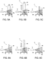
- FIGS. 5A to 5C are views for explaining a determination that is made during a yarn package removal operation in a doffing operation.
- the determination that is made during the yarn package removal operation is concerned with the failure of yarn package removal.
- FIG. 5A illustrates a spindle station 11 and a yarn break sensor 12 before a yarn package removal operation is initiated.
- part of the yarn package 70 of the spindle station 11 is located within the sensing range of the yarn break sensor 12.
- the yarn break sensor 12 senses the presence of that part of the yarn package 70 within its sensing range and outputs a signal indicating the sensing result to the determiner 21.
- the determiner 21 recognizes or determines that the yarn package 70 is present within the sensing range of the yarn break sensor 12.
- the processing of recognition by the determiner 21 may optionally be designed.
- an image processing may be employed to detect a region in the sensing range of the yarn break sensor 12 where the yarn package 70 is present.
- a threshold may be provided to determine whether the quantity of the light in the sensing range exceeds the threshold or not.
- the color of the region to be detected and the criteria for the comparison of the light quantities may be optionally determined in accordance with the color of the yarn package 70 and the like. This also applies to the recognition processing in general that is performed by the determiner 21.
- FIG. 5B illustrates the spindle station 11 and the yarn break sensor 12 during a yarn package removal operation.
- a bobbin 60 (and the yarn package 70 that is wound around the bobbin 60) is moved in a direction indicated by an arrow in FIG. 5B .
- the signal received from the yarn break sensor 12 changes with the movement of the bobbin 60.
- FIG. 5C illustrates the spindle station 11 and the yarn break sensor 12 after the yarn package removal operation has been completed.
- the yarn package 70 is no longer present within the sensing range of the yarn break sensor 12.
- the yarn break sensor 12 senses the absence of the yarn package 70 within its sensing range and outputs a signal indicating the sensing result to the determiner 21.
- the determiner 21 recognizes or determines that the yarn package 70 is not present within the sensing range of the yarn break sensor 12.
- the determiner 21 determines that the doffing operation has been completed successfully (i.e., no doffing failure has occurred). Specifically, when the indication of the signal that is sent from the yarn break sensor 12 has changed from a presence of (a part of) the yarn package 70 to an absence of (the part of) the yarn package 70, the determiner 21 determines that the doffing operation has been completed successfully (i.e., no doffing failure has occurred).
- the determiner 21 determines that the doffing operation is not successfully completed (i.e., a doffing failure has occurred). For example, a detection of the bobbin 60 being not properly removed and remaining on the spindle 50 and part of the yarn package 70 remaining in the sensing range of the yarn break sensor 12 results in a determination of occurrence of a doffing failure.
- FIGS. 6A to 6C are views for explaining a determination that is made during a bobbin placement operation in a doffing operation.
- the determination that is made during the bobbin placement operation is concerned with the failure of bobbin placement.
- FIG. 6A illustrates the spindle station 11 and the yarn break sensor 12 before a bobbin placement operation is initiated.
- no bobbin 60 is present within the sensing range of the yarn break sensor 12.
- the yarn break sensor 12 senses the absence of the bobbin 60 and outputs a signal indicating the sensing result to the determiner 21.
- the determiner 21 recognizes or determines that no bobbin 60 is present within the sensing range of the yarn break sensor 12.
- FIG. 6B illustrates the spindle station 11 and the yarn break sensor 12 during the bobbin placement operation.
- the bobbin 60 having the metallic seat 60a at the bottom thereof is moved in a direction indicated by an arrow in FIG. 6B .
- the indication of the signal received from the yarn break sensor 12 changes with the movement of the bobbin 60.
- FIG. 6C illustrates the spindle station 11 and the yarn break sensor 12 after the bobbin placement operation has been completed.
- the yarn break sensor 12 senses the presence of the bobbin 60 within its sensing range and outputs a signal indicating the sensing result to the determiner 21.
- the determiner 21 recognizes or determines that the bobbin 60 is present within the sensing range of the yarn break sensor 12.
- the determiner 21 determines that the doffing operation has been completed successfully (i.e., no doffing failure has occurred). Specifically, when the indication of the signals sent from the yarn break sensor 12 has changed from an absence of (a part of) the bobbin 60 to a presence of (the part of) the bobbin 60, the determiner 21 determines that the doffing operation has been completed successfully (i.e., no doffing failure has occurred). If no such change is perceived in the indication of the signals, the determiner 21 determines that the doffing operation is not successfully completed (i.e., a doffing failure has occurred).
- the information processing device 20 identifies the spindle station 11 that is associated with the yarn break sensor 12 sending a signal indicating the occurrence of the doffing failure, and sends information indicating the position of the spindle station 11 which has the doffing failure to the mobile terminal 30.
- the mobile terminal 30 receives the positional information of the spindle station 11 from the information processing device 20 and outputs the received positional information to the worker W.
- the form or type of the information indicating the position of the respective spindle stations 11 may optionally be designed.
- a set of information that includes a machine identification information, a spindle line identification information, and a spindle station identification information may be prepared to represent a position of a certain spindle station 11.
- the machine identification information herein refers to the information for identifying a ring spinning machine 10.
- the machine identification information indicates which one of the ring spinning machines 10, shown in FIG. 1 , the spindle station 11 belongs to.
- the spindle line identification information herein refers to the information for identifying a spindle line of a ring spinning machine 10 in which the spindle station 11 is disposed.
- the spindle line identification information indicates which one of the two spindle lines, shown in FIG. 2 , the spindle station 11 belongs to.
- the spindle station identification information herein refers to the information for locating the position of the spindle station 11 in a spindle line.
- the spindle station identification information is represented by a position of the spindle station 11 in the longitudinal direction of the ring spinning machine 10.
- a number is allocated to each of the spindle stations 11 that are arranged in the longitudinal direction of the ring spinning machine 10 so that each spindle station 11 is represented by its own number.
- the worker W moves to the position of the spindle station 11 having the doffing failure based on or in accordance with the information that is output by means of the mobile terminal 30.
- the doffing failure detection device utilizes the detection results of the yarn break sensors 12 in order to output information that indicates the position of the spindle station 11 having the doffing failure.
- the mobile terminal 30 outputs a position of a spindle station 11 that is determined as having a doffing failure by the determiner 21.
- each yarn break sensor 12 includes an optical sensor.
- the specific configuration of the yarn break sensors 12 may optionally be modified by those skilled in the art.
- magnetic type sensors may be employed. In such case, the determination of a doffing failure may be based on whether the metallic seat 60a is present or not in the sensing range of the sensor.
- An example of the yarn break sensor of the magnetic type is mentioned in Japanese Unexamined Patent Application Publication No. 2014-169511 .
- the determination of a yarn package removal failure is made based on the presence of the yarn package 70 in the sensing range of the yarn break sensor 12. However, the determination may be based on the presence of the bobbin 60 or any other components, or otherwise, any other criteria may be employed for the determination.
- the determination of a bobbin placement failure is made based on the presence of the bobbin 60 in the sensing range of the yarn break sensor 12. However, the determination may be based on the presence of any other components, or otherwise, any other criteria may be employed for the determination.
- a doffing failure may optionally be defined.
- the doffing failure includes both the yarn package removal failure and the bobbin placement failure, and determinations are made both during a yarn package removal operation and during a bobbin placement operation.
- the present embodiment may be modified to perform the determination for either one of the failures.
- a failure that occurs during a process associated with the doffing may be employed as a criterion that constitutes a doffing failure.
- the output may also output information indicating a position of a spindle station 11 which has a yarn break detected by its corresponding yarn break sensor 12.
- the mobile terminal 30 is configured to output the position of the spindle station 11 having a doffing failure while the ring spinning machine 10 is in the doffing time (or in the doffing operation), and to output the position of the spindle station 11 having a yarn break while the ring spinning machine 10 is not in the doffing time (or not in the doffing operation).
- the existing components of the ring spinning machine 10 in addition to the existing yarn break sensors 12, can be utilized as the output for outputting a position of the spindle station 11 having a yarn break in the case that, for example, the mobile terminals 30 are the existing components.
- the output of the present embodiment that outputs the position of the spindle station 11 which has a doffing failure need not necessarily be provided by the mobile terminal 30.
- the yarn break indicator lamp 13 that is associated with the spindle station 11 which has a yarn break may be turned on to indicate the position of the spindle station 11.
- the output may be provided by an output device that is associated with the ring spinning machines 10.
- the output may comprise a plurality of displays or computers having a display that are arranged at specified intervals.
- the worker W may be guided to the position of the spindle station 11 which has a doffing failure from the detected location of the worker W.
- the yarn break indicator lamps 13 may be caused to blink sequentially in the direction from the detected location of the worker W toward the position of the spindle station 11 having a doffing failure, as described, for example, in paragraph [0026] of the Japanese Unexamined Patent Application Publication No. 2015-227520 .
- a path or a route from the detected location of the worker W to the position of the spindle station 11 having a doffing failure may be determined and an information of the determined path may be output by means of the output.
- the information processing device 20 and the mobile terminal 30 may be configured by a single computer.
- the mobile terminal 30 includes a determiner 21, and the ring spinning machine 10 includes a wireless transmitter that is configured to transmit detection results of the yarn break sensors 12 to the mobile terminal 30.
- the mobile terminal 30 determines a doffing failure based on the detection results of the yarn break sensors 12 received form the wireless transmitter.
- the outputting of the position of the spindle station 11 which has a doffing failure is provided by visual presentation shown on a display.
- the outputting of the information is not limited thereto, and an audio presentation, such as voice, may be used for the outputting of information.
- a voice information may be output by the mobile terminal 30 or by any other device, such as a speaker associated with the aisles, the ring spinning machines 10, or the information processing device 20.
- a single mobile terminal 30 is used.
- two or more mobile terminals 30 may be used.
- the mobile terminals 30 that are identifiable from each other may be allocated to the workers.
- the method of identifying the mobile terminal 30 to which the information processing device 20 sends information may optionally be designed.
- each worker may enter identification information of the mobile terminal 30 of the worker into the information processing device 20 prior to operation start so that the information processing device 20 can send information based on the identification information of the mobile terminals 30.
- a ring spinning machine (10) that includes a doffing failure detection device has a plurality of spindle stations (11) and a plurality of yarn break detectors (12) provided for the respective spindle stations (11).
- Each spindle station (11) has a spindle (50) on which a yarn package (70) including a bobbin (60) and a yarn is to be formed.
- the doffing failure detection device includes a determiner (21) and an output (13, 30).
- the determiner (21) is configured to determine whether there is a doffing failure for each of the spindle stations (11) based on a change in a signal received from the yarn break detectors (12) during a doffing operation.
- the output (30, 50) is configured to output a position of one of the spindle stations (11) that is determined as having a doffing failure by the determiner (21).
Landscapes
- Engineering & Computer Science (AREA)
- Mechanical Engineering (AREA)
- Textile Engineering (AREA)
- Quality & Reliability (AREA)
- Spinning Or Twisting Of Yarns (AREA)
Abstract
Description
- The present invention relates to a ring spinning machine comprising a doffing failure detection device.
- During a doffing operation of a spinning machine, any failure must be detected and remedied appropriately. Japanese Examined Patent Application Publication No.
S48-3339 - Doffing failure detection devices of the conventional art have a problem that it takes time to locate the position of a doffing failure. For example, according to the configuration of the above-described Publication No.
48-3339 - The present invention has been made to solve the above-described problem and is directed to providing a ring spinning machine comprising a doffing failure detection device that is configured to easily locate a position of a doffing failure that occurs during a doffing operation of the ring spinning machine.
- In accordance with an aspect of the present invention, there is provided a ring spinning machine that includes a doffing failure detection device for detecting a doffing failure that occurs during a doffing operation. The ring spinning machine includes a plurality of spindle stations and a plurality of yarn break detectors provided for the respective spindle stations. Each of the spindle stations has a spindle on which a yarn package including a bobbin and a yarn is to be formed. The doffing failure detection device includes a determiner and an output. The determiner is configured to determine whether there is a doffing failure or not for each of the spindle stations based on a change in a signal received from the yarn break detectors during the doffing operation. The output is configured to output a position of one of the spindle stations that is determined as having a doffing failure by the determiner.
- Other aspects and advantages of the invention will become apparent from the following description and accompanying drawings that illustrate, by way of example the principles of the invention.
- The present invention together with objects and advantages thereof, may best be understood by reference to the following description of the embodiments together with the accompanying drawings in which:
-
FIG. 1 shows an example layout of ring spinning machines comprising a doffing failure detection device according to an embodiment of the present invention; -
FIG. 2 shows an example structure of each ring spinning machine ofFIG. 1 ; -
FIG. 3 shows an example configuration of a spindle station and a yarn break sensor ofFIG. 2 ; -
FIG. 4 shows an example configuration of an information processing device ofFIG. 1 ; -
FIG. 5A is a view for explaining a determination that is made during a yarn package removal operation; -
FIG. 5B is a view for explaining the determination that is made during the yarn package removal operation; -
FIG. 5C is a view for explaining the determination that is made during the yarn package removal operation; -
FIG. 6A is a view for explaining a determination that is made during a bobbin placement operation; -
FIG. 6B is a view for explaining the determination that is made during the bobbin placement operation; and -
FIG. 6C is a view for explaining the determination that is made during the bobbin placement operation. - The following will describe an embodiment of the present invention with reference to the accompanying drawings.
-
FIG. 1 shows an example layout of ring spinning machines comprising a doffing failure detection device according to an embodiment of the present invention. The doffing failure detection device according to the present embodiment is associated with one or morering spinning machines 10. It is preferable that pluralring spinning machines 10 are arranged in rows in a factory or a place as illustrated inFIG. 1 . It should be noted, however, that the present invention can be carried out also in the case where thering spinning machines 10 are not arranged in rows or where there is only a singlering spinning machine 10. - The doffing failure detection device according to the present embodiment includes an
information processing device 20 and amobile terminal 30. Theinformation processing device 20 includes an arithmetic unit and a memory. Theinformation processing device 20 may be configured by using a known computer. Theinformation processing device 20 further includes a communicator that transmits/receives data or information to/from devices provided in association with thering spinning machines 10 and also to/from themobile terminal 30. - The
mobile terminal 30 includes an arithmetic unit and a memory. Themobile terminal 30 may be comprised of a personal mobile computer. Themobile terminal 30 further has a communicator that transmits/receives data or information to/from theinformation processing device 20. Themobile terminal 30 may be a smart phone or a wearable computer. According to the present embodiment, themobile terminal 30 corresponds to the output of the present invention that outputs a position of a spindle station at which a doffing failure has occurred. -
FIG. 2 shows an example structure of the ring spinning machine 10 (only onering spinning machine 10 is shown). Thering spinning machine 10 includes a plurality ofspindle stations 11, a plurality ofyarn break sensors 12, and a plurality of yarnbreak indicator lamps 13. Theyarn break sensors 12 correspond to the yarn break detectors of the present invention and are provided for therespective spindle stations 11. In the present embodiment, the yarnbreak indicator lamps 13 are also provided for therespective spindle stations 11. -
FIG. 3 shows an example configuration of thespindle station 11 and the yarn break sensor 12 (only onespindle station 11 and oneyarn break sensor 12 are shown). Eachyarn break sensor 12 acquires information for determining whether itscorresponding spindle station 11 has a yarn break or not. Thering spinning machine 10 includes asupport member 80, such as a spindle rail, and a plurality ofspindles 50 are fixedly arranged along thesupport member 80. Anempty bobbin 60 is mounted to eachspindle 50, so that thebobbin 60 is supported by thespindle 50 and thesupport member 80. Eachbobbin 60 has ametallic seat 60a at the bottom thereof. During the operation of thering spinning machine 10, a yarn is wound around a part of thebobbin 60 that is located above themetallic seat 60a, so that ayarn package 70 is formed. - According to the present embodiment, each
yarn break sensor 12 includes an optical sensor. Eachyarn break sensor 12 has a sensing range that is shown in gray inFIGS. 3 ,5A to 5C and 6A to 6C . Eachyarn break sensor 12 emits light into the sensing range and determines whether thespindle station 11 has a yarn break or not, based on changes in the amount of light reflected by the yarn or a traveler. In the present invention, the specific method or configuration for the determination of a yarn break is not particularly described. However, such method or configuration may be provided by a device that detects a traveler, such as the one mentioned in Japanese Unexamined Patent Application Publication No.2005-535794 H09-188923 - The behaviors or actions of the
ring spinning machine 10 and other related equipment that are to be taken when a yarn break is detected by any of theyarn break sensors 12 may optionally be designed. For example, the yarnbreak indicator lamps 13 may be configured to be turned on in response to a signal received from their correspondingyarn break sensors 12. - According to the present embodiment, at least a part of the
yarn package 70 or a part of thebobbin 60 is located within the sensing range of eachyarn break sensor 12. In the example ofFIG. 3 , a part of theyarn package 70 is located within the sensing range of its correspondingyarn break sensor 12. -
FIG. 4 shows an example configuration of theinformation processing device 20 according to the present embodiment. Theinformation processing device 20 includes adeterminer 21. The configuration of thedeterminer 21 is built by the arithmetic unit and the memory of theinformation processing device 20 that work in a cooperative manner in accordance with programs stored in the memory. - The
information processing device 20 controls and monitors operation of eachring spinning machines 10, and determines whether eachring spinning machine 10 is in a doffing time or not in a doffing time (e.g., thering spinning machine 10 is in a spinning operation). The doffing time herein refers to a time during which thering spinning machine 10 performs a doffing operation for therespective spindle stations 11 of thering spinning machine 10. It should be noted that the doffing operation herein refers to an operation in which the yarn packages 70 (full cops or full bobbins) are removed from thespindles 50 of thespindle stations 11 and then the bobbins 60 (i.e., empty bobbins) are placed on thespindles 50. That is, the doffing operation includes the yarn package removal operation and the bobbin placement operation. - According to the present embodiment of the present invention, detection of a yarn break is not particularly necessary during the doffing time. The
yarn break sensors 12 are configured to detect a yarn break at least during a specified period of time in a spinning operation of thering spinning machine 10. However, in other periods during the operating time of thering spinning machine 10, such as the doffing time, theyarn break sensors 12 need not detect a yarn break. - The
determiner 21 determines whether there is a doffing failure or not for each of thespindle stations 11, based on a change in a signal received from eachyarn break sensor 12 during a doffing time. According to the present embodiment, theyarn break sensors 12 are configured to output video signals or light quantity signals. Thedeterminer 21 performs determinations based on the signals received from theyarn break sensors 12. According to the present embodiment, the determination by thedeterminer 21 is performed at a specified time that corresponds to the time during which a certain operation of thering spinning machines 10 is performed. For example, thedeterminer 21 makes determinations during a yarn package removal operation and during a bobbin placement operation from/on thespindles 50. - The following will describe in further detail the determination of the
determiner 21 with reference toFIGS. 5A to 5C and 6A to 6C . -
FIGS. 5A to 5C are views for explaining a determination that is made during a yarn package removal operation in a doffing operation. The determination that is made during the yarn package removal operation is concerned with the failure of yarn package removal. -
FIG. 5A illustrates aspindle station 11 and ayarn break sensor 12 before a yarn package removal operation is initiated. Before a yarn package removal operation is started, part of theyarn package 70 of thespindle station 11 is located within the sensing range of theyarn break sensor 12. Theyarn break sensor 12 senses the presence of that part of theyarn package 70 within its sensing range and outputs a signal indicating the sensing result to thedeterminer 21. In response to the signal received from theyarn break sensor 12, thedeterminer 21 recognizes or determines that theyarn package 70 is present within the sensing range of theyarn break sensor 12. - It should be noted that the processing of recognition by the
determiner 21 may optionally be designed. For example, an image processing may be employed to detect a region in the sensing range of theyarn break sensor 12 where theyarn package 70 is present. Alternatively, a threshold may be provided to determine whether the quantity of the light in the sensing range exceeds the threshold or not. In this case, the color of the region to be detected and the criteria for the comparison of the light quantities may be optionally determined in accordance with the color of theyarn package 70 and the like. This also applies to the recognition processing in general that is performed by thedeterminer 21. -
FIG. 5B illustrates thespindle station 11 and theyarn break sensor 12 during a yarn package removal operation. A bobbin 60 (and theyarn package 70 that is wound around the bobbin 60) is moved in a direction indicated by an arrow inFIG. 5B . The signal received from theyarn break sensor 12 changes with the movement of thebobbin 60. -
FIG. 5C illustrates thespindle station 11 and theyarn break sensor 12 after the yarn package removal operation has been completed. At this time, theyarn package 70 is no longer present within the sensing range of theyarn break sensor 12. Theyarn break sensor 12 senses the absence of theyarn package 70 within its sensing range and outputs a signal indicating the sensing result to thedeterminer 21. In response to the signal received from theyarn break sensor 12, thedeterminer 21 recognizes or determines that theyarn package 70 is not present within the sensing range of theyarn break sensor 12. - In this way, during the yarn package removal operation, when the
yarn break sensor 12 senses that theyarn package 70 that was present within the sensing range has disappeared from this range, thedeterminer 21 determines that the doffing operation has been completed successfully (i.e., no doffing failure has occurred). Specifically, when the indication of the signal that is sent from theyarn break sensor 12 has changed from a presence of (a part of) theyarn package 70 to an absence of (the part of) theyarn package 70, thedeterminer 21 determines that the doffing operation has been completed successfully (i.e., no doffing failure has occurred). - If no such change is perceived in the indication of the signals, the
determiner 21 determines that the doffing operation is not successfully completed (i.e., a doffing failure has occurred). For example, a detection of thebobbin 60 being not properly removed and remaining on thespindle 50 and part of theyarn package 70 remaining in the sensing range of theyarn break sensor 12 results in a determination of occurrence of a doffing failure. -
FIGS. 6A to 6C are views for explaining a determination that is made during a bobbin placement operation in a doffing operation. The determination that is made during the bobbin placement operation is concerned with the failure of bobbin placement. -
FIG. 6A illustrates thespindle station 11 and theyarn break sensor 12 before a bobbin placement operation is initiated. Before a bobbin placement operation is started, nobobbin 60 is present within the sensing range of theyarn break sensor 12. Theyarn break sensor 12 senses the absence of thebobbin 60 and outputs a signal indicating the sensing result to thedeterminer 21. In response to the signal received from theyarn break sensor 12, thedeterminer 21 recognizes or determines that nobobbin 60 is present within the sensing range of theyarn break sensor 12. -
FIG. 6B illustrates thespindle station 11 and theyarn break sensor 12 during the bobbin placement operation. Thebobbin 60 having themetallic seat 60a at the bottom thereof is moved in a direction indicated by an arrow inFIG. 6B . The indication of the signal received from theyarn break sensor 12 changes with the movement of thebobbin 60. -
FIG. 6C illustrates thespindle station 11 and theyarn break sensor 12 after the bobbin placement operation has been completed. At this time, (a part of) thebobbin 60 is present within the sensing range of theyarn break sensor 12. Theyarn break sensor 12 senses the presence of thebobbin 60 within its sensing range and outputs a signal indicating the sensing result to thedeterminer 21. In response to the signal received from theyarn break sensor 12, thedeterminer 21 recognizes or determines that thebobbin 60 is present within the sensing range of theyarn break sensor 12. - In this way, during the bobbin placement operation, when the
yarn break sensor 12 senses that thebobbin 60 that was not present within the sensing range has appeared within this range, thedeterminer 21 determines that the doffing operation has been completed successfully (i.e., no doffing failure has occurred). Specifically, when the indication of the signals sent from theyarn break sensor 12 has changed from an absence of (a part of) thebobbin 60 to a presence of (the part of) thebobbin 60, thedeterminer 21 determines that the doffing operation has been completed successfully (i.e., no doffing failure has occurred). If no such change is perceived in the indication of the signals, thedeterminer 21 determines that the doffing operation is not successfully completed (i.e., a doffing failure has occurred). - When a doffing failure has occurred at any one of the
spindle stations 11, theinformation processing device 20 identifies thespindle station 11 that is associated with theyarn break sensor 12 sending a signal indicating the occurrence of the doffing failure, and sends information indicating the position of thespindle station 11 which has the doffing failure to themobile terminal 30. Themobile terminal 30 receives the positional information of thespindle station 11 from theinformation processing device 20 and outputs the received positional information to the worker W. The form or type of the information indicating the position of therespective spindle stations 11 may optionally be designed. For example, a set of information that includes a machine identification information, a spindle line identification information, and a spindle station identification information, may be prepared to represent a position of acertain spindle station 11. The machine identification information herein refers to the information for identifying aring spinning machine 10. For example, the machine identification information indicates which one of thering spinning machines 10, shown inFIG. 1 , thespindle station 11 belongs to. The spindle line identification information herein refers to the information for identifying a spindle line of aring spinning machine 10 in which thespindle station 11 is disposed. For example, the spindle line identification information indicates which one of the two spindle lines, shown inFIG. 2 , thespindle station 11 belongs to. The spindle station identification information herein refers to the information for locating the position of thespindle station 11 in a spindle line. For example, the spindle station identification information is represented by a position of thespindle station 11 in the longitudinal direction of thering spinning machine 10. Alternatively, a number is allocated to each of thespindle stations 11 that are arranged in the longitudinal direction of thering spinning machine 10 so that eachspindle station 11 is represented by its own number. - The worker W moves to the position of the
spindle station 11 having the doffing failure based on or in accordance with the information that is output by means of themobile terminal 30. - As described above, the doffing failure detection device according to the present embodiment utilizes the detection results of the
yarn break sensors 12 in order to output information that indicates the position of thespindle station 11 having the doffing failure. Specifically, themobile terminal 30 outputs a position of aspindle station 11 that is determined as having a doffing failure by thedeterminer 21. With this configuration, the worker W can locate the doffing failure more quickly and easily. - Since the above-described locating of the doffing failure utilizes the existing
yarn break sensors 12, no additional sensors are required for detecting a doffing failure. - The present embodiment of the present invention may be modified as described below. According to the present embodiment, each
yarn break sensor 12 includes an optical sensor. However, the specific configuration of theyarn break sensors 12 may optionally be modified by those skilled in the art. For example, magnetic type sensors may be employed. In such case, the determination of a doffing failure may be based on whether themetallic seat 60a is present or not in the sensing range of the sensor. An example of the yarn break sensor of the magnetic type is mentioned in Japanese Unexamined Patent Application Publication No.2014-169511 - According to the present embodiment, the determination of a yarn package removal failure is made based on the presence of the
yarn package 70 in the sensing range of theyarn break sensor 12. However, the determination may be based on the presence of thebobbin 60 or any other components, or otherwise, any other criteria may be employed for the determination. The determination of a bobbin placement failure is made based on the presence of thebobbin 60 in the sensing range of theyarn break sensor 12. However, the determination may be based on the presence of any other components, or otherwise, any other criteria may be employed for the determination. - It should be noted that "a doffing failure" may optionally be defined. According to the present embodiment, the doffing failure includes both the yarn package removal failure and the bobbin placement failure, and determinations are made both during a yarn package removal operation and during a bobbin placement operation. However, the present embodiment may be modified to perform the determination for either one of the failures. Further, a failure that occurs during a process associated with the doffing may be employed as a criterion that constitutes a doffing failure.
- The output (corresponding to the
mobile terminal 30 in the present embodiment) may also output information indicating a position of aspindle station 11 which has a yarn break detected by its correspondingyarn break sensor 12. In this case, themobile terminal 30 is configured to output the position of thespindle station 11 having a doffing failure while thering spinning machine 10 is in the doffing time (or in the doffing operation), and to output the position of thespindle station 11 having a yarn break while thering spinning machine 10 is not in the doffing time (or not in the doffing operation). According to the configuration, the existing components of thering spinning machine 10, in addition to the existingyarn break sensors 12, can be utilized as the output for outputting a position of thespindle station 11 having a yarn break in the case that, for example, themobile terminals 30 are the existing components. - The output of the present embodiment that outputs the position of the
spindle station 11 which has a doffing failure need not necessarily be provided by themobile terminal 30. For example, the yarnbreak indicator lamp 13 that is associated with thespindle station 11 which has a yarn break may be turned on to indicate the position of thespindle station 11. Alternatively, the output may be provided by an output device that is associated with thering spinning machines 10. Specifically, the output may comprise a plurality of displays or computers having a display that are arranged at specified intervals. - In the case that the doffing failure detection device has a configuration of detecting the location of the worker W, the worker W may be guided to the position of the
spindle station 11 which has a doffing failure from the detected location of the worker W. For example, the yarnbreak indicator lamps 13 may be caused to blink sequentially in the direction from the detected location of the worker W toward the position of thespindle station 11 having a doffing failure, as described, for example, in paragraph [0026] of the Japanese Unexamined Patent Application Publication No.2015-227520 spindle station 11 having a doffing failure may be determined and an information of the determined path may be output by means of the output. - The
information processing device 20 and themobile terminal 30 may be configured by a single computer. For example, themobile terminal 30 includes adeterminer 21, and thering spinning machine 10 includes a wireless transmitter that is configured to transmit detection results of theyarn break sensors 12 to themobile terminal 30. Themobile terminal 30 determines a doffing failure based on the detection results of theyarn break sensors 12 received form the wireless transmitter. - In the present embodiment, the outputting of the position of the
spindle station 11 which has a doffing failure is provided by visual presentation shown on a display. However, the outputting of the information is not limited thereto, and an audio presentation, such as voice, may be used for the outputting of information. In the present embodiment, a voice information may be output by themobile terminal 30 or by any other device, such as a speaker associated with the aisles, thering spinning machines 10, or theinformation processing device 20. - In the present embodiment, a single
mobile terminal 30 is used. However, two or moremobile terminals 30 may be used. For example, themobile terminals 30 that are identifiable from each other may be allocated to the workers. In this case, the method of identifying themobile terminal 30 to which theinformation processing device 20 sends information may optionally be designed. For example, each worker may enter identification information of themobile terminal 30 of the worker into theinformation processing device 20 prior to operation start so that theinformation processing device 20 can send information based on the identification information of themobile terminals 30. - A ring spinning machine (10) that includes a doffing failure detection device is provided. The ring spinning machine (10) has a plurality of spindle stations (11) and a plurality of yarn break detectors (12) provided for the respective spindle stations (11). Each spindle station (11) has a spindle (50) on which a yarn package (70) including a bobbin (60) and a yarn is to be formed. The doffing failure detection device includes a determiner (21) and an output (13, 30). The determiner (21) is configured to determine whether there is a doffing failure for each of the spindle stations (11) based on a change in a signal received from the yarn break detectors (12) during a doffing operation. The output (30, 50) is configured to output a position of one of the spindle stations (11) that is determined as having a doffing failure by the determiner (21).
Claims (4)
- A ring spinning machine (10) comprising a doffing failure detection device for detecting a doffing failure during a doffing operation, the ring spinning machine (10) having a plurality of spindle stations (11) each having a spindle (50) on which a yarn package (70) comprising a bobbin (60) and a yarn is to be formed, and a plurality of yarn break detectors (12) provided for the respective spindle stations (11), characterized in that
the doffing failure detection device includes:a determiner (21) configured to determine whether there is a doffing failure or not for each of the spindle stations (11) based on a change in a signal received from the yarn break detectors (12) during a doffing operation; andan output (13, 30) configured to output a position of one of the spindle stations (11) that is determined as having a doffing failure by the determiner (21). - The ring spinning machine (10) comprising the doffing failure detection device according to claim 1, characterized in that
the doffing operation includes a yarn package removal operation in which the yarn packages (70) are removed from the spindles (50), and
the determiner (21) determines whether there is a doffing failure or not for each of the spindle stations (11) during the yarn package removal operation. - The ring spinning machine (10) comprising the doffing failure detection device according to claim 1 or 2, characterized in that
the doffing operation includes a bobbin placement operation in which the bobbins (60) that are empty are placed on the spindles (50), and
the determiner (21) determines whether there is a doffing failure or not for each of the spindle stations (11) during the bobbin placement operation. - The ring spinning machine (10) comprising the doffing failure detection device according to any one of claims 1 to 3, characterized in that each yarn break detector (12) includes an optical sensor.
Applications Claiming Priority (1)
| Application Number | Priority Date | Filing Date | Title |
|---|---|---|---|
| JP2017078347A JP7287751B2 (en) | 2017-04-11 | 2017-04-11 | Illegal doffing detection device for ring spinning machine |
Publications (2)
| Publication Number | Publication Date |
|---|---|
| EP3388564A1 true EP3388564A1 (en) | 2018-10-17 |
| EP3388564B1 EP3388564B1 (en) | 2022-01-05 |
Family
ID=61906678
Family Applications (1)
| Application Number | Title | Priority Date | Filing Date |
|---|---|---|---|
| EP18165711.5A Active EP3388564B1 (en) | 2017-04-11 | 2018-04-04 | Ring spinning machine comprising a doffing failure detection device |
Country Status (3)
| Country | Link |
|---|---|
| EP (1) | EP3388564B1 (en) |
| JP (1) | JP7287751B2 (en) |
| CN (1) | CN108691044B (en) |
Citations (8)
| Publication number | Priority date | Publication date | Assignee | Title |
|---|---|---|---|---|
| EP0486780A1 (en) * | 1990-11-23 | 1992-05-27 | Zinser Textilmaschinen GmbH | Device for gripping an empty tube or a full bobbin |
| JPH09188923A (en) | 1995-12-28 | 1997-07-22 | Toray Ind Inc | Spinning machine equipped with yarn breakage detection device, twisting machine, and yarn breakage detection method |
| JP2004332141A (en) * | 2003-05-02 | 2004-11-25 | Murata Mach Ltd | Doffing device-equipped spinning machine |
| JP2005535794A (en) | 2002-08-13 | 2005-11-24 | マシーネンファブリク リーター アクチェンゲゼルシャフト | Sensor device for ring spinning machine |
| EP2433889A1 (en) * | 2009-05-22 | 2012-03-28 | Murata Machinery, Ltd. | Yarn winding device and alarm threshold value determination method for detection of rotational faults in a package |
| JP2014169511A (en) | 2013-03-01 | 2014-09-18 | Toyota Industries Corp | Yarn breakage detector for spinning machine |
| JP2015227520A (en) | 2014-06-02 | 2015-12-17 | 株式会社豊田自動織機 | Piecing operation support apparatus for ring type spinning machine |
| EP3031761A1 (en) * | 2014-12-13 | 2016-06-15 | Saurer Germany GmbH & Co. KG | Multi-site textile machine |
Family Cites Families (5)
| Publication number | Priority date | Publication date | Assignee | Title |
|---|---|---|---|---|
| US3403866A (en) * | 1966-03-14 | 1968-10-01 | Leesona Corp | Textile machine |
| JP2000045135A (en) * | 1998-07-27 | 2000-02-15 | Howa Mach Ltd | Operation of singly driven spindle and controller therefor |
| CN202131419U (en) * | 2011-06-14 | 2012-02-01 | 绍兴华裕纺机有限公司 | Broken yarn processing device of ring spinning machine |
| JP5796558B2 (en) * | 2012-09-05 | 2015-10-21 | 株式会社豊田自動織機 | Spinning yarn detection device |
| CN104762709A (en) * | 2013-01-29 | 2015-07-08 | 赵清滨 | Control method for lowering yarn breaks of spinning frame |
-
2017
- 2017-04-11 JP JP2017078347A patent/JP7287751B2/en active Active
-
2018
- 2018-04-04 EP EP18165711.5A patent/EP3388564B1/en active Active
- 2018-04-10 CN CN201810315214.6A patent/CN108691044B/en active Active
Patent Citations (8)
| Publication number | Priority date | Publication date | Assignee | Title |
|---|---|---|---|---|
| EP0486780A1 (en) * | 1990-11-23 | 1992-05-27 | Zinser Textilmaschinen GmbH | Device for gripping an empty tube or a full bobbin |
| JPH09188923A (en) | 1995-12-28 | 1997-07-22 | Toray Ind Inc | Spinning machine equipped with yarn breakage detection device, twisting machine, and yarn breakage detection method |
| JP2005535794A (en) | 2002-08-13 | 2005-11-24 | マシーネンファブリク リーター アクチェンゲゼルシャフト | Sensor device for ring spinning machine |
| JP2004332141A (en) * | 2003-05-02 | 2004-11-25 | Murata Mach Ltd | Doffing device-equipped spinning machine |
| EP2433889A1 (en) * | 2009-05-22 | 2012-03-28 | Murata Machinery, Ltd. | Yarn winding device and alarm threshold value determination method for detection of rotational faults in a package |
| JP2014169511A (en) | 2013-03-01 | 2014-09-18 | Toyota Industries Corp | Yarn breakage detector for spinning machine |
| JP2015227520A (en) | 2014-06-02 | 2015-12-17 | 株式会社豊田自動織機 | Piecing operation support apparatus for ring type spinning machine |
| EP3031761A1 (en) * | 2014-12-13 | 2016-06-15 | Saurer Germany GmbH & Co. KG | Multi-site textile machine |
Also Published As
| Publication number | Publication date |
|---|---|
| EP3388564B1 (en) | 2022-01-05 |
| CN108691044A (en) | 2018-10-23 |
| CN108691044B (en) | 2021-06-18 |
| JP7287751B2 (en) | 2023-06-06 |
| JP2018178302A (en) | 2018-11-15 |
Similar Documents
| Publication | Publication Date | Title |
|---|---|---|
| EP3357637B1 (en) | Machine tool | |
| EP2952461B1 (en) | Ring type spinning machine comprising apparatus for assisting in yarn piecing | |
| US10178302B2 (en) | Safety control device and safety control system | |
| EP3409425A1 (en) | Safety control device, method of controlling safety control device, information processing program, and recording medium | |
| CN101918627B (en) | Device and method for monitoring a plurality of workstations of a ring spinner | |
| JPS6314096B2 (en) | ||
| US20220332522A1 (en) | Overhead carrier vehicle and overhead carrier vehicle system | |
| US11325258B2 (en) | Guidance apparatus and method for failure recovery | |
| JP2018193198A (en) | Productive capacity display controller and method and automatic winder | |
| EP3388564B1 (en) | Ring spinning machine comprising a doffing failure detection device | |
| JP2005248333A (en) | Quality control method of fiber bundle in spinning machine | |
| JP2018167960A (en) | Information processing device | |
| CN105151893B (en) | Method and apparatus for monitoring empty set pipe quality | |
| EP3672207A1 (en) | Textile machine operation support system and method | |
| CN110938901A (en) | Maintenance vehicle and method for the automatic supply of spinning stations of a spinning machine | |
| EP3385415B1 (en) | Ring spinning machine comprising an apparatus for assisting in yarn piecing | |
| JP2022033463A (en) | Wire rope inspection method and device | |
| CN113165827A (en) | Method for monitoring and operating a textile machine and operating device for a textile machine | |
| EP3974364A1 (en) | False-twist texturing machine | |
| EP3950553A1 (en) | Method for detecting presence and/or tracking of a bobbin-holder plate in a winding machine or ring spinning machine, bobbin holder plate for winding machine or ring spinning machine and apparatus for detecting presence and/or tracking of a bobbin in a winding machine or ring spinning machine | |
| JP2018178282A (en) | Yarn defect display device and yarn processing device | |
| CN108455220B (en) | Multi-station material falling detection alarm method | |
| JPH11304449A (en) | Image processing device | |
| EP3666943A1 (en) | Method of controlling spindle of spinning machine and spindle control device | |
| WO2011136431A1 (en) | Method for automatically detecting error of wire bonding process, system, and storage medium |
Legal Events
| Date | Code | Title | Description |
|---|---|---|---|
| PUAI | Public reference made under article 153(3) epc to a published international application that has entered the european phase |
Free format text: ORIGINAL CODE: 0009012 |
|
| STAA | Information on the status of an ep patent application or granted ep patent |
Free format text: STATUS: REQUEST FOR EXAMINATION WAS MADE |
|
| 17P | Request for examination filed |
Effective date: 20180404 |
|
| AK | Designated contracting states |
Kind code of ref document: A1 Designated state(s): AL AT BE BG CH CY CZ DE DK EE ES FI FR GB GR HR HU IE IS IT LI LT LU LV MC MK MT NL NO PL PT RO RS SE SI SK SM TR |
|
| AX | Request for extension of the european patent |
Extension state: BA ME |
|
| GRAP | Despatch of communication of intention to grant a patent |
Free format text: ORIGINAL CODE: EPIDOSNIGR1 |
|
| STAA | Information on the status of an ep patent application or granted ep patent |
Free format text: STATUS: GRANT OF PATENT IS INTENDED |
|
| RIC1 | Information provided on ipc code assigned before grant |
Ipc: B65H 67/00 20060101ALI20210825BHEP Ipc: D01H 9/02 20060101ALI20210825BHEP Ipc: D01H 15/00 20060101ALI20210825BHEP Ipc: D01H 13/14 20060101ALI20210825BHEP Ipc: D01H 15/013 20060101AFI20210825BHEP |
|
| INTG | Intention to grant announced |
Effective date: 20210916 |
|
| GRAS | Grant fee paid |
Free format text: ORIGINAL CODE: EPIDOSNIGR3 |
|
| GRAA | (expected) grant |
Free format text: ORIGINAL CODE: 0009210 |
|
| STAA | Information on the status of an ep patent application or granted ep patent |
Free format text: STATUS: THE PATENT HAS BEEN GRANTED |
|
| AK | Designated contracting states |
Kind code of ref document: B1 Designated state(s): AL AT BE BG CH CY CZ DE DK EE ES FI FR GB GR HR HU IE IS IT LI LT LU LV MC MK MT NL NO PL PT RO RS SE SI SK SM TR |
|
| REG | Reference to a national code |
Ref country code: GB Ref legal event code: FG4D |
|
| REG | Reference to a national code |
Ref country code: CH Ref legal event code: EP |
|
| REG | Reference to a national code |
Ref country code: AT Ref legal event code: REF Ref document number: 1460679 Country of ref document: AT Kind code of ref document: T Effective date: 20220115 |
|
| REG | Reference to a national code |
Ref country code: DE Ref legal event code: R096 Ref document number: 602018028999 Country of ref document: DE |
|
| REG | Reference to a national code |
Ref country code: IE Ref legal event code: FG4D |
|
| REG | Reference to a national code |
Ref country code: LT Ref legal event code: MG9D |
|
| REG | Reference to a national code |
Ref country code: NL Ref legal event code: MP Effective date: 20220105 |
|
| REG | Reference to a national code |
Ref country code: AT Ref legal event code: MK05 Ref document number: 1460679 Country of ref document: AT Kind code of ref document: T Effective date: 20220105 |
|
| PG25 | Lapsed in a contracting state [announced via postgrant information from national office to epo] |
Ref country code: NL Free format text: LAPSE BECAUSE OF FAILURE TO SUBMIT A TRANSLATION OF THE DESCRIPTION OR TO PAY THE FEE WITHIN THE PRESCRIBED TIME-LIMIT Effective date: 20220105 |
|
| PG25 | Lapsed in a contracting state [announced via postgrant information from national office to epo] |
Ref country code: SE Free format text: LAPSE BECAUSE OF FAILURE TO SUBMIT A TRANSLATION OF THE DESCRIPTION OR TO PAY THE FEE WITHIN THE PRESCRIBED TIME-LIMIT Effective date: 20220105 Ref country code: RS Free format text: LAPSE BECAUSE OF FAILURE TO SUBMIT A TRANSLATION OF THE DESCRIPTION OR TO PAY THE FEE WITHIN THE PRESCRIBED TIME-LIMIT Effective date: 20220105 Ref country code: PT Free format text: LAPSE BECAUSE OF FAILURE TO SUBMIT A TRANSLATION OF THE DESCRIPTION OR TO PAY THE FEE WITHIN THE PRESCRIBED TIME-LIMIT Effective date: 20220505 Ref country code: NO Free format text: LAPSE BECAUSE OF FAILURE TO SUBMIT A TRANSLATION OF THE DESCRIPTION OR TO PAY THE FEE WITHIN THE PRESCRIBED TIME-LIMIT Effective date: 20220405 Ref country code: LT Free format text: LAPSE BECAUSE OF FAILURE TO SUBMIT A TRANSLATION OF THE DESCRIPTION OR TO PAY THE FEE WITHIN THE PRESCRIBED TIME-LIMIT Effective date: 20220105 Ref country code: HR Free format text: LAPSE BECAUSE OF FAILURE TO SUBMIT A TRANSLATION OF THE DESCRIPTION OR TO PAY THE FEE WITHIN THE PRESCRIBED TIME-LIMIT Effective date: 20220105 Ref country code: ES Free format text: LAPSE BECAUSE OF FAILURE TO SUBMIT A TRANSLATION OF THE DESCRIPTION OR TO PAY THE FEE WITHIN THE PRESCRIBED TIME-LIMIT Effective date: 20220105 Ref country code: BG Free format text: LAPSE BECAUSE OF FAILURE TO SUBMIT A TRANSLATION OF THE DESCRIPTION OR TO PAY THE FEE WITHIN THE PRESCRIBED TIME-LIMIT Effective date: 20220405 |
|
| PG25 | Lapsed in a contracting state [announced via postgrant information from national office to epo] |
Ref country code: PL Free format text: LAPSE BECAUSE OF FAILURE TO SUBMIT A TRANSLATION OF THE DESCRIPTION OR TO PAY THE FEE WITHIN THE PRESCRIBED TIME-LIMIT Effective date: 20220105 Ref country code: LV Free format text: LAPSE BECAUSE OF FAILURE TO SUBMIT A TRANSLATION OF THE DESCRIPTION OR TO PAY THE FEE WITHIN THE PRESCRIBED TIME-LIMIT Effective date: 20220105 Ref country code: GR Free format text: LAPSE BECAUSE OF FAILURE TO SUBMIT A TRANSLATION OF THE DESCRIPTION OR TO PAY THE FEE WITHIN THE PRESCRIBED TIME-LIMIT Effective date: 20220406 Ref country code: FI Free format text: LAPSE BECAUSE OF FAILURE TO SUBMIT A TRANSLATION OF THE DESCRIPTION OR TO PAY THE FEE WITHIN THE PRESCRIBED TIME-LIMIT Effective date: 20220105 Ref country code: AT Free format text: LAPSE BECAUSE OF FAILURE TO SUBMIT A TRANSLATION OF THE DESCRIPTION OR TO PAY THE FEE WITHIN THE PRESCRIBED TIME-LIMIT Effective date: 20220105 |
|
| PG25 | Lapsed in a contracting state [announced via postgrant information from national office to epo] |
Ref country code: IS Free format text: LAPSE BECAUSE OF FAILURE TO SUBMIT A TRANSLATION OF THE DESCRIPTION OR TO PAY THE FEE WITHIN THE PRESCRIBED TIME-LIMIT Effective date: 20220505 |
|
| REG | Reference to a national code |
Ref country code: DE Ref legal event code: R097 Ref document number: 602018028999 Country of ref document: DE |
|
| PG25 | Lapsed in a contracting state [announced via postgrant information from national office to epo] |
Ref country code: SM Free format text: LAPSE BECAUSE OF FAILURE TO SUBMIT A TRANSLATION OF THE DESCRIPTION OR TO PAY THE FEE WITHIN THE PRESCRIBED TIME-LIMIT Effective date: 20220105 Ref country code: SK Free format text: LAPSE BECAUSE OF FAILURE TO SUBMIT A TRANSLATION OF THE DESCRIPTION OR TO PAY THE FEE WITHIN THE PRESCRIBED TIME-LIMIT Effective date: 20220105 Ref country code: RO Free format text: LAPSE BECAUSE OF FAILURE TO SUBMIT A TRANSLATION OF THE DESCRIPTION OR TO PAY THE FEE WITHIN THE PRESCRIBED TIME-LIMIT Effective date: 20220105 Ref country code: EE Free format text: LAPSE BECAUSE OF FAILURE TO SUBMIT A TRANSLATION OF THE DESCRIPTION OR TO PAY THE FEE WITHIN THE PRESCRIBED TIME-LIMIT Effective date: 20220105 Ref country code: DK Free format text: LAPSE BECAUSE OF FAILURE TO SUBMIT A TRANSLATION OF THE DESCRIPTION OR TO PAY THE FEE WITHIN THE PRESCRIBED TIME-LIMIT Effective date: 20220105 Ref country code: CZ Free format text: LAPSE BECAUSE OF FAILURE TO SUBMIT A TRANSLATION OF THE DESCRIPTION OR TO PAY THE FEE WITHIN THE PRESCRIBED TIME-LIMIT Effective date: 20220105 |
|
| PLBE | No opposition filed within time limit |
Free format text: ORIGINAL CODE: 0009261 |
|
| STAA | Information on the status of an ep patent application or granted ep patent |
Free format text: STATUS: NO OPPOSITION FILED WITHIN TIME LIMIT |
|
| PG25 | Lapsed in a contracting state [announced via postgrant information from national office to epo] |
Ref country code: AL Free format text: LAPSE BECAUSE OF FAILURE TO SUBMIT A TRANSLATION OF THE DESCRIPTION OR TO PAY THE FEE WITHIN THE PRESCRIBED TIME-LIMIT Effective date: 20220105 |
|
| 26N | No opposition filed |
Effective date: 20221006 |
|
| GBPC | Gb: european patent ceased through non-payment of renewal fee |
Effective date: 20220405 |
|
| REG | Reference to a national code |
Ref country code: BE Ref legal event code: MM Effective date: 20220430 |
|
| PG25 | Lapsed in a contracting state [announced via postgrant information from national office to epo] |
Ref country code: MC Free format text: LAPSE BECAUSE OF FAILURE TO SUBMIT A TRANSLATION OF THE DESCRIPTION OR TO PAY THE FEE WITHIN THE PRESCRIBED TIME-LIMIT Effective date: 20220105 Ref country code: LU Free format text: LAPSE BECAUSE OF NON-PAYMENT OF DUE FEES Effective date: 20220404 Ref country code: GB Free format text: LAPSE BECAUSE OF NON-PAYMENT OF DUE FEES Effective date: 20220405 Ref country code: FR Free format text: LAPSE BECAUSE OF NON-PAYMENT OF DUE FEES Effective date: 20220430 |
|
| PG25 | Lapsed in a contracting state [announced via postgrant information from national office to epo] |
Ref country code: SI Free format text: LAPSE BECAUSE OF FAILURE TO SUBMIT A TRANSLATION OF THE DESCRIPTION OR TO PAY THE FEE WITHIN THE PRESCRIBED TIME-LIMIT Effective date: 20220105 Ref country code: BE Free format text: LAPSE BECAUSE OF NON-PAYMENT OF DUE FEES Effective date: 20220430 |
|
| PG25 | Lapsed in a contracting state [announced via postgrant information from national office to epo] |
Ref country code: IE Free format text: LAPSE BECAUSE OF NON-PAYMENT OF DUE FEES Effective date: 20220404 |
|
| P01 | Opt-out of the competence of the unified patent court (upc) registered |
Effective date: 20230519 |
|
| PG25 | Lapsed in a contracting state [announced via postgrant information from national office to epo] |
Ref country code: HU Free format text: LAPSE BECAUSE OF FAILURE TO SUBMIT A TRANSLATION OF THE DESCRIPTION OR TO PAY THE FEE WITHIN THE PRESCRIBED TIME-LIMIT; INVALID AB INITIO Effective date: 20180404 |
|
| PG25 | Lapsed in a contracting state [announced via postgrant information from national office to epo] |
Ref country code: MK Free format text: LAPSE BECAUSE OF FAILURE TO SUBMIT A TRANSLATION OF THE DESCRIPTION OR TO PAY THE FEE WITHIN THE PRESCRIBED TIME-LIMIT Effective date: 20220105 Ref country code: CY Free format text: LAPSE BECAUSE OF FAILURE TO SUBMIT A TRANSLATION OF THE DESCRIPTION OR TO PAY THE FEE WITHIN THE PRESCRIBED TIME-LIMIT Effective date: 20220105 |
|
| PG25 | Lapsed in a contracting state [announced via postgrant information from national office to epo] |
Ref country code: MT Free format text: LAPSE BECAUSE OF FAILURE TO SUBMIT A TRANSLATION OF THE DESCRIPTION OR TO PAY THE FEE WITHIN THE PRESCRIBED TIME-LIMIT Effective date: 20220105 |
|
| REG | Reference to a national code |
Ref country code: DE Ref legal event code: R084 Ref document number: 602018028999 Country of ref document: DE |
|
| PGFP | Annual fee paid to national office [announced via postgrant information from national office to epo] |
Ref country code: DE Payment date: 20250305 Year of fee payment: 8 |
|
| PGFP | Annual fee paid to national office [announced via postgrant information from national office to epo] |
Ref country code: CH Payment date: 20250501 Year of fee payment: 8 |
|
| PG25 | Lapsed in a contracting state [announced via postgrant information from national office to epo] |
Ref country code: TR Free format text: LAPSE BECAUSE OF FAILURE TO SUBMIT A TRANSLATION OF THE DESCRIPTION OR TO PAY THE FEE WITHIN THE PRESCRIBED TIME-LIMIT Effective date: 20220105 |
|
| PGFP | Annual fee paid to national office [announced via postgrant information from national office to epo] |
Ref country code: IT Payment date: 20260320 Year of fee payment: 9 |
|
| REG | Reference to a national code |
Ref country code: CH Ref legal event code: U11 Free format text: ST27 STATUS EVENT CODE: U-0-0-U10-U11 (AS PROVIDED BY THE NATIONAL OFFICE) Effective date: 20260501 |