EP3388349A1 - Canopy of a passenger boarding bridge - Google Patents
Canopy of a passenger boarding bridge Download PDFInfo
- Publication number
- EP3388349A1 EP3388349A1 EP17380011.1A EP17380011A EP3388349A1 EP 3388349 A1 EP3388349 A1 EP 3388349A1 EP 17380011 A EP17380011 A EP 17380011A EP 3388349 A1 EP3388349 A1 EP 3388349A1
- Authority
- EP
- European Patent Office
- Prior art keywords
- cylinder actuator
- canopy
- cylinder
- frame
- rod
- Prior art date
- Legal status (The legal status is an assumption and is not a legal conclusion. Google has not performed a legal analysis and makes no representation as to the accuracy of the status listed.)
- Granted
Links
- 239000000725 suspension Substances 0.000 claims abstract description 17
- 208000027418 Wounds and injury Diseases 0.000 description 3
- 230000006378 damage Effects 0.000 description 3
- 208000014674 injury Diseases 0.000 description 3
- 230000001419 dependent effect Effects 0.000 description 1
- 230000000694 effects Effects 0.000 description 1
- 238000000605 extraction Methods 0.000 description 1
Images


Classifications
-
- E—FIXED CONSTRUCTIONS
- E01—CONSTRUCTION OF ROADS, RAILWAYS, OR BRIDGES
- E01D—CONSTRUCTION OF BRIDGES, ELEVATED ROADWAYS OR VIADUCTS; ASSEMBLY OF BRIDGES
- E01D15/00—Movable or portable bridges; Floating bridges
- E01D15/24—Bridges or similar structures, based on land or on a fixed structure and designed to give access to ships or other floating structures
-
- B—PERFORMING OPERATIONS; TRANSPORTING
- B61—RAILWAYS
- B61D—BODY DETAILS OR KINDS OF RAILWAY VEHICLES
- B61D17/00—Construction details of vehicle bodies
- B61D17/04—Construction details of vehicle bodies with bodies of metal; with composite, e.g. metal and wood body structures
- B61D17/20—Communication passages between coaches; Adaptation of coach ends therefor
- B61D17/22—Communication passages between coaches; Adaptation of coach ends therefor flexible, e.g. bellows
-
- B—PERFORMING OPERATIONS; TRANSPORTING
- B64—AIRCRAFT; AVIATION; COSMONAUTICS
- B64F—GROUND OR AIRCRAFT-CARRIER-DECK INSTALLATIONS SPECIALLY ADAPTED FOR USE IN CONNECTION WITH AIRCRAFT; DESIGNING, MANUFACTURING, ASSEMBLING, CLEANING, MAINTAINING OR REPAIRING AIRCRAFT, NOT OTHERWISE PROVIDED FOR; HANDLING, TRANSPORTING, TESTING OR INSPECTING AIRCRAFT COMPONENTS, NOT OTHERWISE PROVIDED FOR
- B64F1/00—Ground or aircraft-carrier-deck installations
- B64F1/30—Ground or aircraft-carrier-deck installations for embarking or disembarking passengers
- B64F1/305—Bridges extending between terminal building and aircraft, e.g. telescopic, vertically adjustable
-
- E—FIXED CONSTRUCTIONS
- E01—CONSTRUCTION OF ROADS, RAILWAYS, OR BRIDGES
- E01D—CONSTRUCTION OF BRIDGES, ELEVATED ROADWAYS OR VIADUCTS; ASSEMBLY OF BRIDGES
- E01D15/00—Movable or portable bridges; Floating bridges
- E01D15/005—Movable bridges in general ; Constructional elements peculiar to movable bridges
Definitions
- the invention refers to a canopy of a passenger boarding bridge, in particular for boarding a ship or an airplane.
- a passenger boarding bridge connects an airplane with a terminal building via a tunnel.
- the tunnel may be extendible and in particular comprises at least two tunnel sections, which can be telescoped for adjusting the length of the tunnel to the distance between an airplane door and the terminal building.
- the tunnel is movably supported by a drive unit, which can be mounted below a lift system.
- the lift unit is used to adjust the height of the tunnel so that the end of the tunnel facing the airplane is aligned to the door of the airplane.
- a cabin is located, which constitutes the airplane side area of the boarding bridge.
- a movable canopy constitutes a housing of the cabin, which is adaptable to the shape of the airplane fuselage.
- EP 2 803 587 A1 discloses a passenger boarding bridge having a canopy 10.
- the canopy 10 comprising a bellow roof 5, terminating in a plane facing flexible frame 6 having an upper bumper 8 at the upper area of the frame 6.
- the shape of the canopy 10 is to be adjusted to the shape of the fuselage of the airplane in the area, where the PBB is connected to the fuselage.
- Figure 2 shows schematically a cross-section of the fuselage 1 of an Airbus A380.
- the upper PBB 2 U is docked to a door in the second floor of the A380; the lower PBB 2 U is docked to a door in the first floor of the A380. Due to the inclination of the fuselage in the second floor the canopy requires an increased range of operation, compared to a usual passenger boarding bridge. In particular, a large lateral shifting range X of the upper is required.
- the shape of the frame can be adjusted to the shape of the airplane fuselage 1 by a complex suspension system on each side of the canopy, each comprising several levers 14a-d and two actuating cylinders 16.
- the kinematics of the levers 14a-d enables that the lateral shifting range X is larger than the range of operation of the cylinder upper cylinder 16 U .
- the lower cylinder 16 L is provided to support the levers in a vertical direction.
- This object is solved by a canopy according to claim 1; preferred embodiments are subject of the dependent claims and the description.
- the inventive canopy has the advantages that it provides a large range of operation, in particular a large lateral shifting range, with small amount of parts and a simple structure.
- first cylinder actuator is arranged between the fixed frame and the second cylinder actuator
- second cylinder actuator is arranged between the first cylinder actuator and the flexible frame.
- first cylinder actuator and the second cylinder actuator are fixedly connected to each other by a common frame.
- the common frame has main extension direction with a length along a mean pushing direction.
- the common frame may be a closed housing, which covers movable parts of the cylinder actuators for preventing in particular injuries.
- first cylinder actuator has a first cylinder and a first rod and the second cylinder actuator has a second cylinder and a second rod wherein each rod is being transferable between an extracted state and a retracted state.
- first rod and the second rod may are both be fixed at a respective frame side end at the common frame, in particular within the closed housing.
- the cylinder is at least partially accommodated within the common frame, namely the closed housing. So the risk of injuries caused by a cylinder moving into and out of the housing is reduced.
- first cylinder actuator and the second cylinder actuator are arranged parallel to each other.
- the canopy may comprise one suspension system for the left side of the canopy and one suspension system on the right side of the canopy.
- the present description refers to only one suspension system, however it is to be understood that the description is applicable to any second or third suspension system.
- FIG 3 shows an inventive canopy 10.
- the canopy 10 comprising a bellow roof 5, terminating in a plane facing flexible frame 6 having an upper bumper 8 at the upper area of the flexible frame 6.
- the shape of the canopy 10 can be adjusted to the shape of the fuselage of the airplane in the area, where the PBB is connected to the fuselage.
- the canopy is shown in an undocked stated
- the canopy 10 is shown in a deformed state, in which the flexible frame 6 if adapted to the shape of a plane fuselage, comparable to the situation in figure 2 .
- the term "flexible frame” does not require a flexibility of certain parts; it is rather to be understood as describing the fuselage facing side of the canopy, which has the ability to change its overall shape in a certain amount to follow the shape of the fuselage as a consequence of the operation of the cylinders 26. Therefore the suspension system has cylinders 16 as actuators for changing the shape of the canopy.
- the suspension system of the flexible frame comprises two cylinders actuators 16 A , 16 B fixedly coupled to each other.
- a rod 27 A , 27 B and a cylinder 26 A , 26 B is allocated.
- the first cylinder 26 A can push the first rod 27 A in a first pushing direction D A
- the second cylinder 26 B can push the second rod 27 B in a second pushing direction D B .
- the first rod 27 A is arranged between a fixed frame 3 and the first cylinder 26 A .
- the second rod 27 B is arranged between the flexible frame 6 and the second cylinder 26 B .
- a first fixation joint 28 A of the first rod 27 A to the fixed frame 3 is located vertically below than a fixation point 28 B of the second rod 27 B to the flexible frame 6.
- the rods 27 and the cylinders 16 are capable to provide a vertical supporting force component to the flexible frame 6.
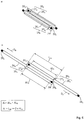
- the cylinder actuators 16 are located parallel to each other as illustrated in figure 4 but are connected in series. Thereby the suspension system is capable to increase its overall length nearly by the double of the length of one cylinder.
- the suspension In the retracted state (the rods are retracted as far as possible into the cylinders) the suspension has in main the length L 29 of one cylinder.
- the rods In the extracted state the rods can be shifted out of the cylinders by ⁇ L A and ⁇ L B , each of which is nearly the length L 29 of one cylinder 16.
- the overall extraction length ⁇ L is ( ⁇ L A + ⁇ L B ). So in sum, the in optimized solution may be capable of nearly triplicating the length of the cylinder.
- the in optimized solution may be capable of nearly triplicating the length of the cylinder.
- the term "suspension” is meant the arrangement of all rods 27 and cylinders 16.
- the cylinders 26 A and 26 B push the respective rods 27 A , 27 B in directions opposite to each other.
- the term "opposite” comprises and exact opposite direction of 180° ( figure 5a ) as well as deviations from the exact opposite direction (shown in figure 5b ) within a limited scope.
- Figure 6 shows an alternative embodiment of the suspension.
- the cylinders actuators 16 are arranged inverted. That means that both rods 27 A , 27 B are connected to each other by the common frame 29.
- the respective cylinders 16 A , 16 B each are connected to the fixed frame 3 or the flexible frame 6 via the respective fixing points 28 A , 28 B .
- Figure 6a shows the cylinders actuators 16 in the retracted state.
- the cylinders 26 are nearly fully accommodated within the common frame 29, which in this case is designed as a closed housing.
- the cylinders are still accommodated within the housing at a small amount. So here the cylinder does not completely leave the housing 29. That means in reverse that during retraction the no end of the cylinder does enter the housing, which could bear a dangerous shear effect for fingers of passengers. The risk of injuries caused is thus reduced.
- the geometrical advantages described with reference to figure 4 are the maintained.
Landscapes
- Engineering & Computer Science (AREA)
- Architecture (AREA)
- Civil Engineering (AREA)
- Structural Engineering (AREA)
- Mechanical Engineering (AREA)
- Aviation & Aerospace Engineering (AREA)
- Life Sciences & Earth Sciences (AREA)
- Wood Science & Technology (AREA)
- Body Structure For Vehicles (AREA)
- Tents Or Canopies (AREA)
Abstract
Description
- The invention refers to a canopy of a passenger boarding bridge, in particular for boarding a ship or an airplane.
- A passenger boarding bridge (PBB) connects an airplane with a terminal building via a tunnel. The tunnel may be extendible and in particular comprises at least two tunnel sections, which can be telescoped for adjusting the length of the tunnel to the distance between an airplane door and the terminal building. The tunnel is movably supported by a drive unit, which can be mounted below a lift system. The lift unit is used to adjust the height of the tunnel so that the end of the tunnel facing the airplane is aligned to the door of the airplane. At the end of the tunnel facing the airplane a cabin is located, which constitutes the airplane side area of the boarding bridge. A movable canopy constitutes a housing of the cabin, which is adaptable to the shape of the airplane fuselage.
-
EP 2 803 587 A1figure 1 of which is shown asfigure 1 in this application, discloses a passenger boarding bridge having acanopy 10. Thecanopy 10 comprising abellow roof 5, terminating in a plane facingflexible frame 6 having anupper bumper 8 at the upper area of theframe 6. During operation the shape of thecanopy 10 is to be adjusted to the shape of the fuselage of the airplane in the area, where the PBB is connected to the fuselage.Figure 2 shows schematically a cross-section of thefuselage 1 of an Airbus A380. The upper PBB 2U is docked to a door in the second floor of the A380; the lower PBB 2U is docked to a door in the first floor of the A380. Due to the inclination of the fuselage in the second floor the canopy requires an increased range of operation, compared to a usual passenger boarding bridge. In particular, a large lateral shifting range X of the upper is required. - Therefore in the canopy shown in
EP 2 803 587 A1airplane fuselage 1 by a complex suspension system on each side of the canopy, each comprisingseveral levers 14a-d and two actuatingcylinders 16. The kinematics of thelevers 14a-d enables that the lateral shifting range X is larger than the range of operation of the cylinderupper cylinder 16U. Thelower cylinder 16L is provided to support the levers in a vertical direction. - It is an object of the invention to provide an improved canopy, in particular comprising a simplified suspension system, and providing a comparable or increased range of operation with respect to conventional solutions. This object is solved by a canopy according to
claim 1; preferred embodiments are subject of the dependent claims and the description. - The inventive canopy has the advantages that it provides a large range of operation, in particular a large lateral shifting range, with small amount of parts and a simple structure.
- In an embodiment the first cylinder actuator is arranged between the fixed frame and the second cylinder actuator, and the second cylinder actuator is arranged between the first cylinder actuator and the flexible frame.
- In an embodiment the first cylinder actuator and the second cylinder actuator are fixedly connected to each other by a common frame. In particular wherein the common frame has main extension direction with a length along a mean pushing direction. In particular the common frame may be a closed housing, which covers movable parts of the cylinder actuators for preventing in particular injuries.
- In an embodiment the first cylinder actuator has a first cylinder and a first rod and the second cylinder actuator has a second cylinder and a second rod wherein each rod is being transferable between an extracted state and a retracted state.
- Thereby the first rod and the second rod may are both be fixed at a respective frame side end at the common frame, in particular within the closed housing.
- In an embodiment in a, in particular fully, extracted state of the cylinders actuators the cylinder is at least partially accommodated within the common frame, namely the closed housing. So the risk of injuries caused by a cylinder moving into and out of the housing is reduced.
- In an embodiment the first cylinder actuator and the second cylinder actuator are arranged parallel to each other.
- In this regard the canopy may comprise one suspension system for the left side of the canopy and one suspension system on the right side of the canopy. The present description refers to only one suspension system, however it is to be understood that the description is applicable to any second or third suspension system.
- The invention is described in more details with the help of the attached figures; herein shows
-
figure 1 a canopy according toEP 2 803 587 A1 -
figure 2 a fuselage of an A380 with two Passenger boarding bridges connected; -
figure 3 an inventive canopy in side view in two operational states having a suspension system in a first embodiment; -
figure 4 the suspension system of the canopy according tofigure 3 in exploded view; -
figure 5 schematically some suitable opposite pushing directions; -
figure 6 a suspension system in a second embodiment suitable for the canopy ofigure 3 . -
Figure 3 shows aninventive canopy 10. Thecanopy 10 comprising abellow roof 5, terminating in a plane facingflexible frame 6 having anupper bumper 8 at the upper area of theflexible frame 6. During operation the shape of thecanopy 10 can be adjusted to the shape of the fuselage of the airplane in the area, where the PBB is connected to the fuselage. Infigure 3a the canopy is shown in an undocked stated, infigure 3b thecanopy 10 is shown in a deformed state, in which theflexible frame 6 if adapted to the shape of a plane fuselage, comparable to the situation infigure 2 . - The term "flexible frame" does not require a flexibility of certain parts; it is rather to be understood as describing the fuselage facing side of the canopy, which has the ability to change its overall shape in a certain amount to follow the shape of the fuselage as a consequence of the operation of the cylinders 26. Therefore the suspension system has
cylinders 16 as actuators for changing the shape of the canopy. - The suspension system of the flexible frame comprises two
cylinders actuators - To each
cylinder actuator 16A, 16B arod first rod 27A in a first pushing direction DA, the second cylinder 26B can push thesecond rod 27Bin a second pushing direction DB. - In the embodiment shown in
figure 1 thefirst rod 27A is arranged between afixed frame 3 and the first cylinder 26A. Thesecond rod 27B is arranged between theflexible frame 6 and the second cylinder 26B. Afirst fixation joint 28A of thefirst rod 27A to thefixed frame 3 is located vertically below than afixation point 28B of thesecond rod 27B to theflexible frame 6. Thus therods 27 and thecylinders 16 are capable to provide a vertical supporting force component to theflexible frame 6. - The
cylinder actuators 16 are located parallel to each other as illustrated infigure 4 but are connected in series. Thereby the suspension system is capable to increase its overall length nearly by the double of the length of one cylinder. In the retracted state (the rods are retracted as far as possible into the cylinders) the suspension has in main the length L29 of one cylinder. In the extracted state the rods can be shifted out of the cylinders by ΔLA and ΔLB, each of which is nearly the length L29 of onecylinder 16. In sum the overall extraction length ΔL is (ΔLA + ΔLB). So in sum, the in optimized solution may be capable of nearly triplicating the length of the cylinder. With the term "suspension" is meant the arrangement of allrods 27 andcylinders 16. - The cylinders 26A and 26B push the
respective rods figure 5a ) as well as deviations from the exact opposite direction (shown infigure 5b ) within a limited scope. -
Figure 6 shows an alternative embodiment of the suspension. Compared to the embodiment offigure 3 thecylinders actuators 16 are arranged inverted. That means that bothrods common frame 29. Therespective cylinders fixed frame 3 or theflexible frame 6 via therespective fixing points -
Figure 6a shows thecylinders actuators 16 in the retracted state. Thereby the cylinders 26 are nearly fully accommodated within thecommon frame 29, which in this case is designed as a closed housing. In the fully extracted state, shown infigure 6b , the cylinders are still accommodated within the housing at a small amount. So here the cylinder does not completely leave thehousing 29. That means in reverse that during retraction the no end of the cylinder does enter the housing, which could bear a dangerous shear effect for fingers of passengers. The risk of injuries caused is thus reduced. The geometrical advantages described with reference tofigure 4 are the maintained. -
- 1
- fuselage
- 2
- passenger boarding bridge
- 3
- fixed frame
- 5
- bellow roof
- 6
- flexible frame
- 8
- upper bumper
- 10
- canopy
- 14
- lever
- 16
- cylinder actuator
- 26
- cylinder
- 27
- rod
- 28
- fixing joint
- 29
- common frame / closed housing
- 30
- frame side end
- 30
- frame side end of cylinder actuator
- D
- pushing direction
- X
- lateral shifting range
- L
- Length
Claims (8)
- Canopy (10) for a passenger boarding bridge (2), comprising- a fixed frame (3) attached or to be attached at passenger boarding bridge (2),- a flexible frame (6), to be aligned to a fuselage (1) of a plane or a ship,- a bellow roof (5) clamped between the fixed frame (3) and the flexible frame (6),- a suspension system comprising a first cylinder actuator (16A) and a second cylinder actuator (16B), wherein the first cylinder actuator (16A) is adapted to provide a pushing force in first pushing direction (DA) and the second cylinder actuator (16B) is adapted to provide a pushing force in a second pushing direction (DB),characterized in
that the first cylinder actuator (16A) and the second cylinder actuator (16B) are connected in series and that the first pushing direction (DA) is opposite to the second pushing direction (DB). - Canopy (10) according to the preceding claim,
characterized in
that the first cylinder actuator (16A) is arranged between the fixed frame (3) and the second cylinder actuator (16B), and
that the second cylinder actuator (16B) is arranged between the first cylinder actuator (16A) and the flexible frame (6). - Canopy (10) according to any of the preceding claims,
characterized in
that the first cylinder actuator (16A) and the second cylinder actuator (16B) are fixedly connected to each other by a common frame (29), in particular a closed housing, in particular wherein the common frame (29) has main extension direction with a length (L29) along a mean pushing direction (D). - Canopy (10) according to any of the preceding claims,
characterized in
that the first cylinder actuator (16A) has a first cylinder (26A) and a first rod (27A) and that the second cylinder actuator (16B) has a second cylinder (26B) and a second rod (27B), wherein each rod (27) is being transferable between an extracted state and a retracted state. - Canopy (10) according to claims 3 and 4,
characterized in
that the first rod (27A) and the second rod (27B) are both fixed at a respective frame side end (30A, 30B) at the common frame (29), in particular within the closed housing (29). - Canopy (10) according to any of the preceding claims,
characterized in
that in a, in particular fully, extracted state of the cylinders actuators (16) the cylinder (26) is at least partially accommodated within the common frame, namely the closed housing (29). - Canopy (10) according to any of the preceding claims,
characterized in
that the first cylinder actuator (16A) and the second cylinder actuator (16B) are arranged parallel to each other. - Passenger boarding bridge comprising a canopy according to any of the preceding claims.
Priority Applications (4)
| Application Number | Priority Date | Filing Date | Title |
|---|---|---|---|
| EP17380011.1A EP3388349B1 (en) | 2017-04-10 | 2017-04-10 | Canopy and passenger boarding bridge comprising a canopy |
| ES17380011T ES2770072T3 (en) | 2017-04-10 | 2017-04-10 | Awning and passenger boarding bridge that includes an awning |
| PCT/EP2018/058864 WO2018189053A1 (en) | 2017-04-10 | 2018-04-06 | Canopy of a passenger boarding bridge |
| US16/604,250 US10697137B2 (en) | 2017-04-10 | 2018-04-06 | Canopy of a passenger boarding bridge |
Applications Claiming Priority (1)
| Application Number | Priority Date | Filing Date | Title |
|---|---|---|---|
| EP17380011.1A EP3388349B1 (en) | 2017-04-10 | 2017-04-10 | Canopy and passenger boarding bridge comprising a canopy |
Publications (2)
| Publication Number | Publication Date |
|---|---|
| EP3388349A1 true EP3388349A1 (en) | 2018-10-17 |
| EP3388349B1 EP3388349B1 (en) | 2019-10-30 |
Family
ID=58664624
Family Applications (1)
| Application Number | Title | Priority Date | Filing Date |
|---|---|---|---|
| EP17380011.1A Active EP3388349B1 (en) | 2017-04-10 | 2017-04-10 | Canopy and passenger boarding bridge comprising a canopy |
Country Status (4)
| Country | Link |
|---|---|
| US (1) | US10697137B2 (en) |
| EP (1) | EP3388349B1 (en) |
| ES (1) | ES2770072T3 (en) |
| WO (1) | WO2018189053A1 (en) |
Citations (5)
| Publication number | Priority date | Publication date | Assignee | Title |
|---|---|---|---|---|
| US4120067A (en) * | 1978-03-15 | 1978-10-17 | Abex Corporation | Articulated closure for a passenger loading bridge |
| DE3023885A1 (en) * | 1980-06-26 | 1982-01-14 | Trepel Ag, 6200 Wiesbaden | Bellows for aircraft access gangway - has sliding extension on guide rollers, with pivoted hydraulic ram and bumper |
| DE3311754A1 (en) * | 1982-04-21 | 1983-10-27 | SOVAM, Parthenay, Deux-Sèvres | APPLICATION DEVICE, IN PARTICULAR FOR VEHICLES FOR THE TRANSPORT OF PASSENGERS AT AIRPORTS |
| US4817223A (en) * | 1987-02-03 | 1989-04-04 | Hubner Gummi-Und Kunststoff Gmbh | Airport passenger ramp |
| EP2803587A1 (en) | 2013-05-18 | 2014-11-19 | Hübner GmbH & Co. KG | Air passenger boarding bridge or steps with a U-shaped portal frame for mounting an awning at the front of the bridge or steps |
Family Cites Families (8)
| Publication number | Priority date | Publication date | Assignee | Title |
|---|---|---|---|---|
| US3363273A (en) * | 1965-10-23 | 1968-01-16 | Hoffman Taff Inc | Loading dock door enclosure |
| NL6807580A (en) * | 1968-05-29 | 1969-12-02 | ||
| US3581331A (en) * | 1968-10-01 | 1971-06-01 | Brown Eng Co Inc | Fire protection shield |
| BE756506A (en) * | 1969-09-25 | 1971-03-01 | Budd Co | COVERED AND RETRACTABLE GATEWAY FOR VEHICLE OR GATEWAY |
| US3641604A (en) * | 1970-05-27 | 1972-02-15 | Boothe Airside Services | Closure apparatus |
| US3843987A (en) * | 1973-03-28 | 1974-10-29 | Global Erectors Inc | Contour adapted passenger loading ramp |
| US4333195A (en) * | 1980-11-24 | 1982-06-08 | Lichti Robert D | Fire protective walkway apparatus |
| CN100471760C (en) * | 2007-03-22 | 2009-03-25 | 中国国际海运集装箱(集团)股份有限公司 | Opening and closing device for boarding bridge canopy |
-
2017
- 2017-04-10 ES ES17380011T patent/ES2770072T3/en active Active
- 2017-04-10 EP EP17380011.1A patent/EP3388349B1/en active Active
-
2018
- 2018-04-06 US US16/604,250 patent/US10697137B2/en not_active Expired - Fee Related
- 2018-04-06 WO PCT/EP2018/058864 patent/WO2018189053A1/en not_active Ceased
Patent Citations (5)
| Publication number | Priority date | Publication date | Assignee | Title |
|---|---|---|---|---|
| US4120067A (en) * | 1978-03-15 | 1978-10-17 | Abex Corporation | Articulated closure for a passenger loading bridge |
| DE3023885A1 (en) * | 1980-06-26 | 1982-01-14 | Trepel Ag, 6200 Wiesbaden | Bellows for aircraft access gangway - has sliding extension on guide rollers, with pivoted hydraulic ram and bumper |
| DE3311754A1 (en) * | 1982-04-21 | 1983-10-27 | SOVAM, Parthenay, Deux-Sèvres | APPLICATION DEVICE, IN PARTICULAR FOR VEHICLES FOR THE TRANSPORT OF PASSENGERS AT AIRPORTS |
| US4817223A (en) * | 1987-02-03 | 1989-04-04 | Hubner Gummi-Und Kunststoff Gmbh | Airport passenger ramp |
| EP2803587A1 (en) | 2013-05-18 | 2014-11-19 | Hübner GmbH & Co. KG | Air passenger boarding bridge or steps with a U-shaped portal frame for mounting an awning at the front of the bridge or steps |
Also Published As
| Publication number | Publication date |
|---|---|
| US20200149233A1 (en) | 2020-05-14 |
| WO2018189053A1 (en) | 2018-10-18 |
| ES2770072T3 (en) | 2020-06-30 |
| US10697137B2 (en) | 2020-06-30 |
| EP3388349B1 (en) | 2019-10-30 |
Similar Documents
| Publication | Publication Date | Title |
|---|---|---|
| CN104024106B (en) | Elevating flap assembly, airfoil for aircraft and aircraft | |
| US10899431B2 (en) | System for driving and guiding of a multifunctional trailing edge control surface on an aircraft | |
| WO2011046923A3 (en) | Aircraft elevator system and method | |
| CN103879542B (en) | A kind of aircraft head and the aircraft with the head | |
| CN102069916A (en) | Boarding bridge with a minute approaching device and a shock absorbing part and operation method thereof | |
| US9975409B2 (en) | Arrangement with a cover for a vehicle roof | |
| EP3025954B1 (en) | Aircraft fuselage section | |
| US7596826B2 (en) | Device for passenger bridges for aircraft | |
| EP3388349B1 (en) | Canopy and passenger boarding bridge comprising a canopy | |
| JP5587483B2 (en) | Boarding bridge connections and boarding bridges | |
| EP3575206A1 (en) | System for driving a flap arrangement between a retracted position and an extended position | |
| EP2261107B1 (en) | Work machine cab | |
| US20090072089A1 (en) | Aircraft door assembly, and aircraft fuselage comprising such an aircraft door assembly | |
| EP2889216B1 (en) | Aircraft with a trimmable horizontal stabilizer having the pivot elements in its forward side | |
| EP3577000B1 (en) | Gap bridging device and method for operating a gap bridging device | |
| JP4700661B2 (en) | Boarding bridge | |
| US9981536B2 (en) | Assembly having a cover for a vehicle roof | |
| JP2017132373A (en) | Boarding bridge | |
| EP2444276A1 (en) | Vehicle seat | |
| CN212033212U (en) | Vehicle shroud antenna device and vehicle | |
| EP3173332A1 (en) | Aircraft interior fitting component system and method for manufacturing an aircraft interior fitting component system | |
| EP3575207A1 (en) | System for driving a flap arrangement between a retracted position and an extended position | |
| CN104405426A (en) | Horizontal thrust device of hydraulic support and hydraulic support | |
| EP3293047B1 (en) | System for lifting the loading platform and vehicle for transporting motor vehicles equipped with such system for lifting the loading platform | |
| CN214828696U (en) | Lifting platform for remote synchronous operation |
Legal Events
| Date | Code | Title | Description |
|---|---|---|---|
| PUAI | Public reference made under article 153(3) epc to a published international application that has entered the european phase |
Free format text: ORIGINAL CODE: 0009012 |
|
| STAA | Information on the status of an ep patent application or granted ep patent |
Free format text: STATUS: THE APPLICATION HAS BEEN PUBLISHED |
|
| AK | Designated contracting states |
Kind code of ref document: A1 Designated state(s): AL AT BE BG CH CY CZ DE DK EE ES FI FR GB GR HR HU IE IS IT LI LT LU LV MC MK MT NL NO PL PT RO RS SE SI SK SM TR |
|
| AX | Request for extension of the european patent |
Extension state: BA ME |
|
| RAP1 | Party data changed (applicant data changed or rights of an application transferred) |
Owner name: THYSSENKRUPP AIRPORT SOLUTIONS S.A. Owner name: THYSSENKRUPP AG |
|
| STAA | Information on the status of an ep patent application or granted ep patent |
Free format text: STATUS: REQUEST FOR EXAMINATION WAS MADE |
|
| RIN1 | Information on inventor provided before grant (corrected) |
Inventor name: FERNANDEZ, JOSE FERMIN VIGIL Inventor name: ESPINA, MANUEL HERNANDEZ Inventor name: BERMEJO, ANTONIO MURIAS Inventor name: FERNANDEZ, JOSE RAMON BUSTO |
|
| 17P | Request for examination filed |
Effective date: 20190417 |
|
| RBV | Designated contracting states (corrected) |
Designated state(s): AL AT BE BG CH CY CZ DE DK EE ES FI FR GB GR HR HU IE IS IT LI LT LU LV MC MK MT NL NO PL PT RO RS SE SI SK SM TR |
|
| GRAP | Despatch of communication of intention to grant a patent |
Free format text: ORIGINAL CODE: EPIDOSNIGR1 |
|
| STAA | Information on the status of an ep patent application or granted ep patent |
Free format text: STATUS: GRANT OF PATENT IS INTENDED |
|
| INTG | Intention to grant announced |
Effective date: 20190814 |
|
| RIN1 | Information on inventor provided before grant (corrected) |
Inventor name: FERNANDEZ, JOSE RAMON BUSTO Inventor name: ESPINA, MANUEL HERNANDEZ Inventor name: FERNANDEZ, JOSE FERMIN VIGIL Inventor name: BERMEJO, ANTONIO MURIAS |
|
| GRAS | Grant fee paid |
Free format text: ORIGINAL CODE: EPIDOSNIGR3 |
|
| GRAA | (expected) grant |
Free format text: ORIGINAL CODE: 0009210 |
|
| STAA | Information on the status of an ep patent application or granted ep patent |
Free format text: STATUS: THE PATENT HAS BEEN GRANTED |
|
| AK | Designated contracting states |
Kind code of ref document: B1 Designated state(s): AL AT BE BG CH CY CZ DE DK EE ES FI FR GB GR HR HU IE IS IT LI LT LU LV MC MK MT NL NO PL PT RO RS SE SI SK SM TR |
|
| REG | Reference to a national code |
Ref country code: GB Ref legal event code: FG4D |
|
| REG | Reference to a national code |
Ref country code: CH Ref legal event code: EP |
|
| REG | Reference to a national code |
Ref country code: DE Ref legal event code: R096 Ref document number: 602017008228 Country of ref document: DE |
|
| REG | Reference to a national code |
Ref country code: AT Ref legal event code: REF Ref document number: 1195887 Country of ref document: AT Kind code of ref document: T Effective date: 20191115 |
|
| REG | Reference to a national code |
Ref country code: IE Ref legal event code: FG4D |
|
| REG | Reference to a national code |
Ref country code: SE Ref legal event code: TRGR |
|
| REG | Reference to a national code |
Ref country code: LT Ref legal event code: MG4D |
|
| PG25 | Lapsed in a contracting state [announced via postgrant information from national office to epo] |
Ref country code: PT Free format text: LAPSE BECAUSE OF FAILURE TO SUBMIT A TRANSLATION OF THE DESCRIPTION OR TO PAY THE FEE WITHIN THE PRESCRIBED TIME-LIMIT Effective date: 20200302 Ref country code: LV Free format text: LAPSE BECAUSE OF FAILURE TO SUBMIT A TRANSLATION OF THE DESCRIPTION OR TO PAY THE FEE WITHIN THE PRESCRIBED TIME-LIMIT Effective date: 20191030 Ref country code: NL Free format text: LAPSE BECAUSE OF FAILURE TO SUBMIT A TRANSLATION OF THE DESCRIPTION OR TO PAY THE FEE WITHIN THE PRESCRIBED TIME-LIMIT Effective date: 20191030 Ref country code: PL Free format text: LAPSE BECAUSE OF FAILURE TO SUBMIT A TRANSLATION OF THE DESCRIPTION OR TO PAY THE FEE WITHIN THE PRESCRIBED TIME-LIMIT Effective date: 20191030 Ref country code: LT Free format text: LAPSE BECAUSE OF FAILURE TO SUBMIT A TRANSLATION OF THE DESCRIPTION OR TO PAY THE FEE WITHIN THE PRESCRIBED TIME-LIMIT Effective date: 20191030 Ref country code: BG Free format text: LAPSE BECAUSE OF FAILURE TO SUBMIT A TRANSLATION OF THE DESCRIPTION OR TO PAY THE FEE WITHIN THE PRESCRIBED TIME-LIMIT Effective date: 20200130 Ref country code: NO Free format text: LAPSE BECAUSE OF FAILURE TO SUBMIT A TRANSLATION OF THE DESCRIPTION OR TO PAY THE FEE WITHIN THE PRESCRIBED TIME-LIMIT Effective date: 20200130 Ref country code: FI Free format text: LAPSE BECAUSE OF FAILURE TO SUBMIT A TRANSLATION OF THE DESCRIPTION OR TO PAY THE FEE WITHIN THE PRESCRIBED TIME-LIMIT Effective date: 20191030 |
|
| REG | Reference to a national code |
Ref country code: NL Ref legal event code: MP Effective date: 20191030 |
|
| PG25 | Lapsed in a contracting state [announced via postgrant information from national office to epo] |
Ref country code: IS Free format text: LAPSE BECAUSE OF FAILURE TO SUBMIT A TRANSLATION OF THE DESCRIPTION OR TO PAY THE FEE WITHIN THE PRESCRIBED TIME-LIMIT Effective date: 20200229 Ref country code: RS Free format text: LAPSE BECAUSE OF FAILURE TO SUBMIT A TRANSLATION OF THE DESCRIPTION OR TO PAY THE FEE WITHIN THE PRESCRIBED TIME-LIMIT Effective date: 20191030 Ref country code: HR Free format text: LAPSE BECAUSE OF FAILURE TO SUBMIT A TRANSLATION OF THE DESCRIPTION OR TO PAY THE FEE WITHIN THE PRESCRIBED TIME-LIMIT Effective date: 20191030 |
|
| PG25 | Lapsed in a contracting state [announced via postgrant information from national office to epo] |
Ref country code: AL Free format text: LAPSE BECAUSE OF FAILURE TO SUBMIT A TRANSLATION OF THE DESCRIPTION OR TO PAY THE FEE WITHIN THE PRESCRIBED TIME-LIMIT Effective date: 20191030 |
|
| REG | Reference to a national code |
Ref country code: ES Ref legal event code: FG2A Ref document number: 2770072 Country of ref document: ES Kind code of ref document: T3 Effective date: 20200630 |
|
| PG25 | Lapsed in a contracting state [announced via postgrant information from national office to epo] |
Ref country code: DK Free format text: LAPSE BECAUSE OF FAILURE TO SUBMIT A TRANSLATION OF THE DESCRIPTION OR TO PAY THE FEE WITHIN THE PRESCRIBED TIME-LIMIT Effective date: 20191030 Ref country code: EE Free format text: LAPSE BECAUSE OF FAILURE TO SUBMIT A TRANSLATION OF THE DESCRIPTION OR TO PAY THE FEE WITHIN THE PRESCRIBED TIME-LIMIT Effective date: 20191030 Ref country code: CZ Free format text: LAPSE BECAUSE OF FAILURE TO SUBMIT A TRANSLATION OF THE DESCRIPTION OR TO PAY THE FEE WITHIN THE PRESCRIBED TIME-LIMIT Effective date: 20191030 Ref country code: RO Free format text: LAPSE BECAUSE OF FAILURE TO SUBMIT A TRANSLATION OF THE DESCRIPTION OR TO PAY THE FEE WITHIN THE PRESCRIBED TIME-LIMIT Effective date: 20191030 |
|
| PGFP | Annual fee paid to national office [announced via postgrant information from national office to epo] |
Ref country code: ES Payment date: 20200629 Year of fee payment: 4 |
|
| REG | Reference to a national code |
Ref country code: DE Ref legal event code: R097 Ref document number: 602017008228 Country of ref document: DE |
|
| RAP2 | Party data changed (patent owner data changed or rights of a patent transferred) |
Owner name: THYSSENKRUPP AIRPORT SOLUTIONS S.A. |
|
| REG | Reference to a national code |
Ref country code: AT Ref legal event code: MK05 Ref document number: 1195887 Country of ref document: AT Kind code of ref document: T Effective date: 20191030 |
|
| PG25 | Lapsed in a contracting state [announced via postgrant information from national office to epo] |
Ref country code: SM Free format text: LAPSE BECAUSE OF FAILURE TO SUBMIT A TRANSLATION OF THE DESCRIPTION OR TO PAY THE FEE WITHIN THE PRESCRIBED TIME-LIMIT Effective date: 20191030 Ref country code: IT Free format text: LAPSE BECAUSE OF FAILURE TO SUBMIT A TRANSLATION OF THE DESCRIPTION OR TO PAY THE FEE WITHIN THE PRESCRIBED TIME-LIMIT Effective date: 20191030 Ref country code: SK Free format text: LAPSE BECAUSE OF FAILURE TO SUBMIT A TRANSLATION OF THE DESCRIPTION OR TO PAY THE FEE WITHIN THE PRESCRIBED TIME-LIMIT Effective date: 20191030 |
|
| PLBE | No opposition filed within time limit |
Free format text: ORIGINAL CODE: 0009261 |
|
| STAA | Information on the status of an ep patent application or granted ep patent |
Free format text: STATUS: NO OPPOSITION FILED WITHIN TIME LIMIT |
|
| 26N | No opposition filed |
Effective date: 20200731 |
|
| PG25 | Lapsed in a contracting state [announced via postgrant information from national office to epo] |
Ref country code: SI Free format text: LAPSE BECAUSE OF FAILURE TO SUBMIT A TRANSLATION OF THE DESCRIPTION OR TO PAY THE FEE WITHIN THE PRESCRIBED TIME-LIMIT Effective date: 20191030 Ref country code: MC Free format text: LAPSE BECAUSE OF FAILURE TO SUBMIT A TRANSLATION OF THE DESCRIPTION OR TO PAY THE FEE WITHIN THE PRESCRIBED TIME-LIMIT Effective date: 20191030 Ref country code: AT Free format text: LAPSE BECAUSE OF FAILURE TO SUBMIT A TRANSLATION OF THE DESCRIPTION OR TO PAY THE FEE WITHIN THE PRESCRIBED TIME-LIMIT Effective date: 20191030 |
|
| REG | Reference to a national code |
Ref country code: CH Ref legal event code: PL |
|
| REG | Reference to a national code |
Ref country code: DE Ref legal event code: R081 Ref document number: 602017008228 Country of ref document: DE Owner name: THYSSENKRUPP AIRPORT SOLUTIONS S.A., MIERES, ES Free format text: FORMER OWNERS: THYSSENKRUPP AG, 45143 ESSEN, DE; THYSSENKRUPP AIRPORT SOLUTIONS S.A., MIERES, ASTURIAS, ES |
|
| PG25 | Lapsed in a contracting state [announced via postgrant information from national office to epo] |
Ref country code: CH Free format text: LAPSE BECAUSE OF NON-PAYMENT OF DUE FEES Effective date: 20200430 Ref country code: LI Free format text: LAPSE BECAUSE OF NON-PAYMENT OF DUE FEES Effective date: 20200430 Ref country code: LU Free format text: LAPSE BECAUSE OF NON-PAYMENT OF DUE FEES Effective date: 20200410 |
|
| REG | Reference to a national code |
Ref country code: BE Ref legal event code: MM Effective date: 20200430 |
|
| PG25 | Lapsed in a contracting state [announced via postgrant information from national office to epo] |
Ref country code: BE Free format text: LAPSE BECAUSE OF NON-PAYMENT OF DUE FEES Effective date: 20200430 |
|
| PG25 | Lapsed in a contracting state [announced via postgrant information from national office to epo] |
Ref country code: IE Free format text: LAPSE BECAUSE OF NON-PAYMENT OF DUE FEES Effective date: 20200410 |
|
| PGFP | Annual fee paid to national office [announced via postgrant information from national office to epo] |
Ref country code: FR Payment date: 20210423 Year of fee payment: 5 Ref country code: DE Payment date: 20210420 Year of fee payment: 5 |
|
| PGFP | Annual fee paid to national office [announced via postgrant information from national office to epo] |
Ref country code: GB Payment date: 20210422 Year of fee payment: 5 Ref country code: SE Payment date: 20210420 Year of fee payment: 5 Ref country code: TR Payment date: 20210407 Year of fee payment: 5 |
|
| PG25 | Lapsed in a contracting state [announced via postgrant information from national office to epo] |
Ref country code: MT Free format text: LAPSE BECAUSE OF FAILURE TO SUBMIT A TRANSLATION OF THE DESCRIPTION OR TO PAY THE FEE WITHIN THE PRESCRIBED TIME-LIMIT Effective date: 20191030 Ref country code: CY Free format text: LAPSE BECAUSE OF FAILURE TO SUBMIT A TRANSLATION OF THE DESCRIPTION OR TO PAY THE FEE WITHIN THE PRESCRIBED TIME-LIMIT Effective date: 20191030 |
|
| REG | Reference to a national code |
Ref country code: ES Ref legal event code: FD2A Effective date: 20220629 |
|
| PG25 | Lapsed in a contracting state [announced via postgrant information from national office to epo] |
Ref country code: MK Free format text: LAPSE BECAUSE OF FAILURE TO SUBMIT A TRANSLATION OF THE DESCRIPTION OR TO PAY THE FEE WITHIN THE PRESCRIBED TIME-LIMIT Effective date: 20191030 |
|
| PG25 | Lapsed in a contracting state [announced via postgrant information from national office to epo] |
Ref country code: GR Free format text: LAPSE BECAUSE OF FAILURE TO SUBMIT A TRANSLATION OF THE DESCRIPTION OR TO PAY THE FEE WITHIN THE PRESCRIBED TIME-LIMIT Effective date: 20191030 Ref country code: ES Free format text: LAPSE BECAUSE OF NON-PAYMENT OF DUE FEES Effective date: 20210411 |
|
| REG | Reference to a national code |
Ref country code: DE Ref legal event code: R119 Ref document number: 602017008228 Country of ref document: DE |
|
| REG | Reference to a national code |
Ref country code: SE Ref legal event code: EUG |
|
| GBPC | Gb: european patent ceased through non-payment of renewal fee |
Effective date: 20220410 |
|
| PG25 | Lapsed in a contracting state [announced via postgrant information from national office to epo] |
Ref country code: SE Free format text: LAPSE BECAUSE OF NON-PAYMENT OF DUE FEES Effective date: 20220411 Ref country code: GB Free format text: LAPSE BECAUSE OF NON-PAYMENT OF DUE FEES Effective date: 20220410 Ref country code: FR Free format text: LAPSE BECAUSE OF NON-PAYMENT OF DUE FEES Effective date: 20220430 Ref country code: DE Free format text: LAPSE BECAUSE OF NON-PAYMENT OF DUE FEES Effective date: 20221103 |