EP3388232A1 - Method for producing a sandwich structure and sandwich structure produced according to the method - Google Patents
Method for producing a sandwich structure and sandwich structure produced according to the method Download PDFInfo
- Publication number
- EP3388232A1 EP3388232A1 EP18000281.8A EP18000281A EP3388232A1 EP 3388232 A1 EP3388232 A1 EP 3388232A1 EP 18000281 A EP18000281 A EP 18000281A EP 3388232 A1 EP3388232 A1 EP 3388232A1
- Authority
- EP
- European Patent Office
- Prior art keywords
- honeycomb core
- thermoplastic material
- cover layer
- sandwich structure
- adhesive
- Prior art date
- Legal status (The legal status is an assumption and is not a legal conclusion. Google has not performed a legal analysis and makes no representation as to the accuracy of the status listed.)
- Granted
Links
- 238000000034 method Methods 0.000 title claims abstract description 55
- 238000004519 manufacturing process Methods 0.000 title claims abstract description 12
- 239000012815 thermoplastic material Substances 0.000 claims abstract description 70
- 239000000853 adhesive Substances 0.000 claims abstract description 33
- 230000001070 adhesive effect Effects 0.000 claims abstract description 33
- 238000010438 heat treatment Methods 0.000 claims abstract description 20
- 238000003825 pressing Methods 0.000 claims abstract description 14
- 239000000843 powder Substances 0.000 claims description 9
- XLYOFNOQVPJJNP-UHFFFAOYSA-N water Substances O XLYOFNOQVPJJNP-UHFFFAOYSA-N 0.000 claims description 9
- 239000007788 liquid Substances 0.000 claims description 6
- 238000002844 melting Methods 0.000 claims description 6
- 230000008018 melting Effects 0.000 claims description 6
- 230000005855 radiation Effects 0.000 claims description 6
- 230000001939 inductive effect Effects 0.000 claims description 4
- 238000007598 dipping method Methods 0.000 claims description 3
- 238000000227 grinding Methods 0.000 claims description 3
- RNFJDJUURJAICM-UHFFFAOYSA-N 2,2,4,4,6,6-hexaphenoxy-1,3,5-triaza-2$l^{5},4$l^{5},6$l^{5}-triphosphacyclohexa-1,3,5-triene Chemical compound N=1P(OC=2C=CC=CC=2)(OC=2C=CC=CC=2)=NP(OC=2C=CC=CC=2)(OC=2C=CC=CC=2)=NP=1(OC=1C=CC=CC=1)OC1=CC=CC=C1 RNFJDJUURJAICM-UHFFFAOYSA-N 0.000 claims description 2
- 239000003063 flame retardant Substances 0.000 claims description 2
- 235000011837 pasties Nutrition 0.000 claims description 2
- 239000004417 polycarbonate Substances 0.000 claims description 2
- 229920000515 polycarbonate Polymers 0.000 claims description 2
- 239000007921 spray Substances 0.000 claims description 2
- 238000003466 welding Methods 0.000 claims description 2
- 241000264877 Hippospongia communis Species 0.000 description 85
- 239000000463 material Substances 0.000 description 9
- 229920001169 thermoplastic Polymers 0.000 description 5
- 239000004416 thermosoftening plastic Substances 0.000 description 5
- 239000004760 aramid Substances 0.000 description 4
- 229920003235 aromatic polyamide Polymers 0.000 description 4
- 239000002313 adhesive film Substances 0.000 description 3
- 230000006835 compression Effects 0.000 description 3
- 238000007906 compression Methods 0.000 description 3
- 239000002657 fibrous material Substances 0.000 description 3
- 239000012530 fluid Substances 0.000 description 3
- 229920005989 resin Polymers 0.000 description 3
- 239000011347 resin Substances 0.000 description 3
- 239000004640 Melamine resin Substances 0.000 description 2
- 229920000877 Melamine resin Polymers 0.000 description 2
- 238000001816 cooling Methods 0.000 description 2
- 230000005484 gravity Effects 0.000 description 2
- 238000005507 spraying Methods 0.000 description 2
- 229920001187 thermosetting polymer Polymers 0.000 description 2
- KXGFMDJXCMQABM-UHFFFAOYSA-N 2-methoxy-6-methylphenol Chemical compound [CH]OC1=CC=CC([CH])=C1O KXGFMDJXCMQABM-UHFFFAOYSA-N 0.000 description 1
- 229920000049 Carbon (fiber) Polymers 0.000 description 1
- 239000004823 Reactive adhesive Substances 0.000 description 1
- XAGFODPZIPBFFR-UHFFFAOYSA-N aluminium Chemical compound [Al] XAGFODPZIPBFFR-UHFFFAOYSA-N 0.000 description 1
- 229910052782 aluminium Inorganic materials 0.000 description 1
- 239000004917 carbon fiber Substances 0.000 description 1
- 239000003795 chemical substances by application Substances 0.000 description 1
- 239000002131 composite material Substances 0.000 description 1
- 238000007596 consolidation process Methods 0.000 description 1
- 238000010276 construction Methods 0.000 description 1
- 230000008020 evaporation Effects 0.000 description 1
- 238000001704 evaporation Methods 0.000 description 1
- 239000004744 fabric Substances 0.000 description 1
- 239000000835 fiber Substances 0.000 description 1
- 239000003365 glass fiber Substances 0.000 description 1
- 239000012943 hotmelt Substances 0.000 description 1
- 239000011159 matrix material Substances 0.000 description 1
- 230000005499 meniscus Effects 0.000 description 1
- VNWKTOKETHGBQD-UHFFFAOYSA-N methane Chemical compound C VNWKTOKETHGBQD-UHFFFAOYSA-N 0.000 description 1
- 239000004745 nonwoven fabric Substances 0.000 description 1
- 239000005011 phenolic resin Substances 0.000 description 1
- 229920001568 phenolic resin Polymers 0.000 description 1
- 239000011265 semifinished product Substances 0.000 description 1
- 238000009736 wetting Methods 0.000 description 1
Images

Classifications
-
- B—PERFORMING OPERATIONS; TRANSPORTING
- B32—LAYERED PRODUCTS
- B32B—LAYERED PRODUCTS, i.e. PRODUCTS BUILT-UP OF STRATA OF FLAT OR NON-FLAT, e.g. CELLULAR OR HONEYCOMB, FORM
- B32B3/00—Layered products comprising a layer with external or internal discontinuities or unevennesses, or a layer of non-planar form; Layered products having particular features of form
- B32B3/10—Layered products comprising a layer with external or internal discontinuities or unevennesses, or a layer of non-planar form; Layered products having particular features of form characterised by a discontinuous layer, i.e. formed of separate pieces of material
- B32B3/12—Layered products comprising a layer with external or internal discontinuities or unevennesses, or a layer of non-planar form; Layered products having particular features of form characterised by a discontinuous layer, i.e. formed of separate pieces of material characterised by a layer of regularly- arranged cells, e.g. a honeycomb structure
-
- B—PERFORMING OPERATIONS; TRANSPORTING
- B32—LAYERED PRODUCTS
- B32B—LAYERED PRODUCTS, i.e. PRODUCTS BUILT-UP OF STRATA OF FLAT OR NON-FLAT, e.g. CELLULAR OR HONEYCOMB, FORM
- B32B15/00—Layered products comprising a layer of metal
- B32B15/04—Layered products comprising a layer of metal comprising metal as the main or only constituent of a layer, which is next to another layer of the same or of a different material
- B32B15/08—Layered products comprising a layer of metal comprising metal as the main or only constituent of a layer, which is next to another layer of the same or of a different material of synthetic resin
-
- B—PERFORMING OPERATIONS; TRANSPORTING
- B32—LAYERED PRODUCTS
- B32B—LAYERED PRODUCTS, i.e. PRODUCTS BUILT-UP OF STRATA OF FLAT OR NON-FLAT, e.g. CELLULAR OR HONEYCOMB, FORM
- B32B15/00—Layered products comprising a layer of metal
- B32B15/20—Layered products comprising a layer of metal comprising aluminium or copper
-
- B—PERFORMING OPERATIONS; TRANSPORTING
- B32—LAYERED PRODUCTS
- B32B—LAYERED PRODUCTS, i.e. PRODUCTS BUILT-UP OF STRATA OF FLAT OR NON-FLAT, e.g. CELLULAR OR HONEYCOMB, FORM
- B32B27/00—Layered products comprising a layer of synthetic resin
- B32B27/06—Layered products comprising a layer of synthetic resin as the main or only constituent of a layer, which is next to another layer of the same or of a different material
- B32B27/10—Layered products comprising a layer of synthetic resin as the main or only constituent of a layer, which is next to another layer of the same or of a different material of paper or cardboard
-
- B—PERFORMING OPERATIONS; TRANSPORTING
- B32—LAYERED PRODUCTS
- B32B—LAYERED PRODUCTS, i.e. PRODUCTS BUILT-UP OF STRATA OF FLAT OR NON-FLAT, e.g. CELLULAR OR HONEYCOMB, FORM
- B32B29/00—Layered products comprising a layer of paper or cardboard
- B32B29/002—Layered products comprising a layer of paper or cardboard as the main or only constituent of a layer, which is next to another layer of the same or of a different material
-
- B—PERFORMING OPERATIONS; TRANSPORTING
- B32—LAYERED PRODUCTS
- B32B—LAYERED PRODUCTS, i.e. PRODUCTS BUILT-UP OF STRATA OF FLAT OR NON-FLAT, e.g. CELLULAR OR HONEYCOMB, FORM
- B32B37/00—Methods or apparatus for laminating, e.g. by curing or by ultrasonic bonding
- B32B37/0038—Methods or apparatus for laminating, e.g. by curing or by ultrasonic bonding involving application of liquid to the layers prior to lamination, e.g. wet laminating
-
- B—PERFORMING OPERATIONS; TRANSPORTING
- B32—LAYERED PRODUCTS
- B32B—LAYERED PRODUCTS, i.e. PRODUCTS BUILT-UP OF STRATA OF FLAT OR NON-FLAT, e.g. CELLULAR OR HONEYCOMB, FORM
- B32B37/00—Methods or apparatus for laminating, e.g. by curing or by ultrasonic bonding
- B32B37/14—Methods or apparatus for laminating, e.g. by curing or by ultrasonic bonding characterised by the properties of the layers
- B32B37/146—Methods or apparatus for laminating, e.g. by curing or by ultrasonic bonding characterised by the properties of the layers whereby one or more of the layers is a honeycomb structure
-
- B—PERFORMING OPERATIONS; TRANSPORTING
- B32—LAYERED PRODUCTS
- B32B—LAYERED PRODUCTS, i.e. PRODUCTS BUILT-UP OF STRATA OF FLAT OR NON-FLAT, e.g. CELLULAR OR HONEYCOMB, FORM
- B32B7/00—Layered products characterised by the relation between layers; Layered products characterised by the relative orientation of features between layers, or by the relative values of a measurable parameter between layers, i.e. products comprising layers having different physical, chemical or physicochemical properties; Layered products characterised by the interconnection of layers
- B32B7/04—Interconnection of layers
- B32B7/12—Interconnection of layers using interposed adhesives or interposed materials with bonding properties
-
- B—PERFORMING OPERATIONS; TRANSPORTING
- B32—LAYERED PRODUCTS
- B32B—LAYERED PRODUCTS, i.e. PRODUCTS BUILT-UP OF STRATA OF FLAT OR NON-FLAT, e.g. CELLULAR OR HONEYCOMB, FORM
- B32B2250/00—Layers arrangement
- B32B2250/02—2 layers
-
- B—PERFORMING OPERATIONS; TRANSPORTING
- B32—LAYERED PRODUCTS
- B32B—LAYERED PRODUCTS, i.e. PRODUCTS BUILT-UP OF STRATA OF FLAT OR NON-FLAT, e.g. CELLULAR OR HONEYCOMB, FORM
- B32B2250/00—Layers arrangement
- B32B2250/03—3 layers
-
- B—PERFORMING OPERATIONS; TRANSPORTING
- B32—LAYERED PRODUCTS
- B32B—LAYERED PRODUCTS, i.e. PRODUCTS BUILT-UP OF STRATA OF FLAT OR NON-FLAT, e.g. CELLULAR OR HONEYCOMB, FORM
- B32B2250/00—Layers arrangement
- B32B2250/40—Symmetrical or sandwich layers, e.g. ABA, ABCBA, ABCCBA
-
- B—PERFORMING OPERATIONS; TRANSPORTING
- B32—LAYERED PRODUCTS
- B32B—LAYERED PRODUCTS, i.e. PRODUCTS BUILT-UP OF STRATA OF FLAT OR NON-FLAT, e.g. CELLULAR OR HONEYCOMB, FORM
- B32B2255/00—Coating on the layer surface
- B32B2255/06—Coating on the layer surface on metal layer
-
- B—PERFORMING OPERATIONS; TRANSPORTING
- B32—LAYERED PRODUCTS
- B32B—LAYERED PRODUCTS, i.e. PRODUCTS BUILT-UP OF STRATA OF FLAT OR NON-FLAT, e.g. CELLULAR OR HONEYCOMB, FORM
- B32B2255/00—Coating on the layer surface
- B32B2255/12—Coating on the layer surface on paper layer
-
- B—PERFORMING OPERATIONS; TRANSPORTING
- B32—LAYERED PRODUCTS
- B32B—LAYERED PRODUCTS, i.e. PRODUCTS BUILT-UP OF STRATA OF FLAT OR NON-FLAT, e.g. CELLULAR OR HONEYCOMB, FORM
- B32B2255/00—Coating on the layer surface
- B32B2255/26—Polymeric coating
-
- B—PERFORMING OPERATIONS; TRANSPORTING
- B32—LAYERED PRODUCTS
- B32B—LAYERED PRODUCTS, i.e. PRODUCTS BUILT-UP OF STRATA OF FLAT OR NON-FLAT, e.g. CELLULAR OR HONEYCOMB, FORM
- B32B2255/00—Coating on the layer surface
- B32B2255/28—Multiple coating on one surface
-
- B—PERFORMING OPERATIONS; TRANSPORTING
- B32—LAYERED PRODUCTS
- B32B—LAYERED PRODUCTS, i.e. PRODUCTS BUILT-UP OF STRATA OF FLAT OR NON-FLAT, e.g. CELLULAR OR HONEYCOMB, FORM
- B32B2262/00—Composition or structural features of fibres which form a fibrous or filamentary layer or are present as additives
- B32B2262/02—Synthetic macromolecular fibres
- B32B2262/0261—Polyamide fibres
- B32B2262/0269—Aromatic polyamide fibres
-
- B—PERFORMING OPERATIONS; TRANSPORTING
- B32—LAYERED PRODUCTS
- B32B—LAYERED PRODUCTS, i.e. PRODUCTS BUILT-UP OF STRATA OF FLAT OR NON-FLAT, e.g. CELLULAR OR HONEYCOMB, FORM
- B32B2307/00—Properties of the layers or laminate
- B32B2307/30—Properties of the layers or laminate having particular thermal properties
- B32B2307/306—Resistant to heat
- B32B2307/3065—Flame resistant or retardant, fire resistant or retardant
-
- B—PERFORMING OPERATIONS; TRANSPORTING
- B32—LAYERED PRODUCTS
- B32B—LAYERED PRODUCTS, i.e. PRODUCTS BUILT-UP OF STRATA OF FLAT OR NON-FLAT, e.g. CELLULAR OR HONEYCOMB, FORM
- B32B2605/00—Vehicles
-
- B—PERFORMING OPERATIONS; TRANSPORTING
- B32—LAYERED PRODUCTS
- B32B—LAYERED PRODUCTS, i.e. PRODUCTS BUILT-UP OF STRATA OF FLAT OR NON-FLAT, e.g. CELLULAR OR HONEYCOMB, FORM
- B32B2605/00—Vehicles
- B32B2605/08—Cars
-
- B—PERFORMING OPERATIONS; TRANSPORTING
- B32—LAYERED PRODUCTS
- B32B—LAYERED PRODUCTS, i.e. PRODUCTS BUILT-UP OF STRATA OF FLAT OR NON-FLAT, e.g. CELLULAR OR HONEYCOMB, FORM
- B32B2605/00—Vehicles
- B32B2605/18—Aircraft
Definitions
- the invention relates to a method for producing a sandwich structure with a honeycomb core and at least one cover layer.
- a sandwich structure may be a component of an interior trim, as well as a flap, a lid, a luggage compartment element, a galley or toilet, or a floorboard.
- sandwich structures consist of a honeycomb core, which is also referred to as honeycomb.
- the honeycomb core can be made of paper, which is made for example of aromatic polyamide (meta-aramid).
- the paper can z. B. be impregnated with a melamine resin or phenolic resin.
- the honeycomb core may have a hexagonal cell structure or sine honeycomb and allows the production of rigid components, which have a particularly low weight.
- the sandwich structure may also have folded cores.
- the sandwich structure is provided with a cover layer on at least one side.
- the cover layer may be formed by a woven, knitted or a combination of fabric and nonwoven. So far, predominantly thermoset cover layers have been used.
- a fiber material such as glass fiber or carbon fiber, is impregnated with a resin and pre-crosslinked, these semi-finished products are referred to as prepreg.
- the resin of the prepreg material flows during curing and forms a meniscus between webs of the honeycomb core and the cover layer. In this way, a good adhesion is possible.
- a method for producing a sandwich structure is known.
- a lightweight board which has a thermoplastic support core, connected to a fiber material by liquid thermoplastic material is supplied. Under pressure, the liquid thermoplastic material is rolled into the fiber material, infiltrated and then cooled.
- a honeycomb core is to be provided with a thermoplastic cover layer, it is not possible to use the production method customary for thermosetting resins, since the viscosity of the thermoplastic matrix is too high.
- adhesive films are usually used, which are introduced between the cover layer and the honeycomb core.
- Such adhesive films can be based on a reactive adhesive system, alternatively, a hot-melt system can be used.
- the adhesives can be used in the form of films, films or nonwovens. All such materials and methods of manufacture have the disadvantage that they are comparatively expensive, increase the weight of the sandwich structure and worsen the fire behavior.
- the invention is therefore based on the object to provide a method for producing a sandwich structure, which is suitable for a thermoplastic cover layer and allows sufficient adhesion between the honeycomb core and the cover layer.
- an adhesive is applied to the honeycomb core prior to the application of the powder also referred to below as powdered thermoplastic material.
- the adhesive serves to the powdered thermoplastic material temporarily to fix the honeycomb core until the top layer is placed and the compression of the honeycomb core is carried out under heating.
- an adhesive is used, which is only temporarily available and then z. B. is eliminated by evaporation.
- the adhesive which is also referred to as adhesion agent, is applied only in the region on the honeycomb core, on which then the powdered thermoplastic material is applied. Accordingly, the honeycomb core is not provided over its entire thickness with the adhesive, but only on its outer surface, optionally on both opposite outer surfaces and in directly adjacent areas.
- the invention is based on the recognition that in order to achieve a good adhesion between the honeycomb core and the cover layer, a thermoplastic material in powder form can be applied to at least one side of the honeycomb core. The powdery material is then located at the contact surface between the honeycomb core and the cover layer. After placing the cover layer of the honeycomb core provided with the powdery thermoplastic material, the assembly is heated so that the powdered thermoplastic material plasticizes. By pressing the composite of the honeycomb core and the at least one cover layer, a firm mechanical connection is created between the honeycomb core and the cover layer.
- the inventive method has the advantage that it can be dispensed with the attachment of separate adhesive films or other adhesive systems, which otherwise lead to an undesirable increase in weight.
- the powdered thermoplastic material is applied only in the areas in which a bonding is to take place, already satisfies a comparatively small amount of the powdery thermoplastic material. Another advantage is that the powdered thermoplastic material can be applied in an automated manufacturing process.
- a preferred variant of the method according to the invention provides that the powdered thermoplastic material is applied to both sides of the honeycomb core, which are each provided with a cover layer, heated and pressed.
- the powdered thermoplastic material is applied to both sides of the honeycomb core, which are each provided with a cover layer, heated and pressed.
- plate-shaped or three-dimensional sandwich structures can be produced.
- These may be, for example, components of the interior trim of a vehicle or aircraft, as well
- single or multiple curved structures such as flaps, lids or doors and the like can be produced.
- a liquid adhesive is used in the process of the invention.
- a liquid adhesive can be applied very sparingly.
- the adhesive is applied in the inventive method by a dipping process or by a spray process on the honeycomb core.
- a dipping process in which the honeycomb core is immersed in a controlled manner in an adhesive bath, the wetting with the adhesive can be controlled exactly.
- the honeycomb core can be guided, for example, past a stationary spraying device. It is also conceivable to arrange the honeycomb core in a holding device, which is designed so that only one area to be sprayed is exposed, while areas not to be sprayed are covered. In this way it is ensured that only those areas of the honeycomb core are provided with the adhesive, which are then provided with the powdery thermoplastic material.
- water is used as an adhesive. This has the advantage that the water evaporates during heating and melting of the thermoplastic material.
- an adhesive may also be used as the adhesive.
- the powdered thermoplastic material by pressing the honeycomb core into the powder or pasty mass containing the powder and / or by sprinkling with the powdery thermoplastic material and / or by powdering by means of compressed air on the honeycomb core, in particular by Swirling the powdered thermoplastic material is applied. If an adhesive has previously been applied, the powdered thermoplastic material only adheres to the wetted areas with the adhesive. This can ensure that only the outer contact surface of the honeycomb core, on which the cover layer is placed, and optionally a region directly adjacent thereto, is provided with the powdery thermoplastic material.
- the heating and plasticizing of the powdered thermoplastic material takes place, for. B. by infrared radiation or by means of a furnace.
- the heating and plasticizing can take place with a heatable press or by means of a hot air system or with an electrically conductive honeycomb core by means of inductive heating.
- an adhesive is used as an adhesive, it can be crosslinked by adding heat, UV light or air humidity. Infrared radiation can be generated by a heating field.
- An electrically conductive honeycomb core may be, for example, a honeycomb core made of aluminum honeycombs.
- the powdery thermoplastic material By heating the honeycomb core provided with the cover layer, the powdery thermoplastic material is plasticized. This means that it becomes fluid due to the increase in temperature, so that it combines with the cover layer during pressing. It is not necessary that the thermoplastic material be brought into a completely molten state.
- the temperature to which the overcoated honeycomb core is heated is set so that the thermoplastic material is sufficiently fluid to bond to the topsheet, yet it must not be so fluid that under the action of gravity the contact surface runs.
- the powdered thermoplastic material applied to the honeycomb core is cooled to a temperature below its melting point. This ensures adhesion of the thermoplastic material to the honeycomb core without the presence of an adhesive. If a liquid has previously been used as an adhesive, it will evaporate on heating. As the thermoplastic material cools below its melting point, it adheres to the honeycomb core.
- the compression of the honeycomb core can take place in a pressing process.
- individual pieces can be pressed in a hot press or there is a continuous pressing in a double belt press or a semi-continuous pressing in an interval press.
- the pressing of the honeycomb core in a furnace process or in an autoclave process or in a welding process or in a process with inductive heating respectively. All of the mentioned methods serve to ensure sufficient adhesion between the honeycomb core and the cover layer.
- the thermoplastic material forms a bond between the honeycomb core and the cover layer.
- the thermoplastic material is only at the contact points where it is needed to make the connection. However, it is not applied flat on the top layer, which results in a considerable weight savings and cost reduction.
- powdered polycarbonate is used as a thermoplastic material.
- powdered polycarbonate is used as a thermoplastic material.
- other powdered thermoplastic materials in question which allow good adhesion between the honeycomb core and the cover layer.
- thermoplastic material is used.
- the invention relates to a sandwich structure with a honeycomb core and at least one cover layer, which is produced by a method of the type described.
- Fig. 1 shows the first step of the process for producing a sandwich structure.
- the honeycomb core 1 shown schematically consists in this embodiment of a paper based on aromatic polyamide fibers (meta-aramid), which is impregnated with a melamine resin.
- an adhesive is applied to the honeycomb core 1.
- the adhesive is water 2 received in a container 3.
- the honeycomb core 1 is lowered parallel to its underside in the direction of the arrow 5, until the in the middle representation of Fig. 1 shown position is reached.
- the underside 4 of the honeycomb core 1 is wetted in this way with water 2 as an adhesive.
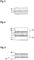
- Fig. 2 shows the next step of the process for producing the sandwich structure.
- a powdered thermoplastic material 7 is located in a container 8.
- the honeycomb core 1 is lowered parallel to its underside 4 in the direction of the arrow 5 and into the powdery thermoplastic material 7, which forms a powder bed, pressed.
- the honeycomb core 1 is lowered so far that its wetted with water 2 lower portion is completely pressed into the powder bed.
- the honeycomb core 1 as in the right representation of Fig. 2 is shown, raised in the direction of arrow 6. Since the lower portion of the honeycomb core 1 is wetted with water 2, the powdery thermoplastic material 7 is temporarily fixed to the honeycomb core 1.
- a third process step which in Fig. 3 is shown, the fixed on the honeycomb core 1 powdered thermoplastic material 7 is melted.
- This will - as in Fig. 3 is shown - the honeycomb core 1 is reversed, so that the provided with the powdery thermoplastic material 7 side is up.
- the honeycomb core 1 provided with the powdery thermoplastic material 7 is heated by infrared radiation 9.
- the infrared radiation 9 causes the powdered thermoplastic material 7 is plasticized.
- the powdery thermoplastic material 7 is heated until it reaches its melting temperature.
- the temperature to which the powdery thermoplastic material 7 fixed to the honeycomb core 1 is heated is chosen so that it does not run down under the action of gravity. Following this, the honeycomb core 1 is allowed to cool.
- honeycomb core 1 is to be provided on both sides with a cover layer, which are in the FIGS. 1 to 3 shown process steps on the back of the honeycomb core 1 repeated.
- a fourth process step which in Fig. 4 1, the honeycomb core 1 provided with the thermoplastic material 7 is joined to cover layers 10, 11.
- cover layers 10, 11 are placed on both sides of the honeycomb core 1.
- the honeycomb core 1 provided with the cover layers 10, 11 is reheated.
- the heating takes place in this embodiment in a heated press.
- the thermoplastic material 7 plasticizes again.
- the press comprises two relatively adjustable press components 12, 13, which can be moved toward one another in the direction of the arrows 14, 15. To consolidate the press components 12, 13 are moved towards each other, so that the cover layers 10, 11 are pressed in the heated state with the provided with the thermoplastic material 7 honeycomb core 1.
- the sandwich structure 16 consists of the honeycomb core 1 and the cover layers 10, 11.
- the honeycomb core 1 is wetted with water as an adhesive. Subsequently, as in Fig. 2 is shown, the powdered thermoplastic material 7 is applied, which adheres to the moistened honeycomb core 1.
- the two cover layers 10, 11 are placed directly on the two sides of the honeycomb core 1. Subsequently, the heating of this arrangement is carried out to a temperature at which plasticizes the thermoplastic material. In this embodiment, consolidation takes place in an oven. By means of a suitable device, the cover layers 10, 11 are pressed against the honeycomb core 1, so that the cover layers 10, 11 abut the honeycomb core 1 over their entire surface. After cooling, the obtained in Fig. 5 shown sandwich structure 16.
- the powdered thermoplastic material 7 is applied by powdering the honeycomb core 1 by means of compressed air.
- the powdered thermoplastic material 7 is applied by means of a compressed air gun.
- the honeycomb core 1 is located in a holding device which covers those areas that are not to be provided with the powdery thermoplastic material 7. Accordingly, the device is designed such that only one side of the honeycomb core 1 and the region directly adjoining it are provided with the powdery thermoplastic material 7.
Abstract
Die Erfindung betrifft ein Verfahren zur Herstellung einer Sandwichstruktur (16) mit einem Wabenkern (1) und wenigstens einer Decklage (10, 11), mit den folgenden Schritten: - Aufbringen eines pulverförmigen thermoplastischen Materials (7) auf eine Seite des Wabenkerns (1), - Auflegen der Decklage (10, 11) auf die mit dem pulverförmigen thermoplastischen Material (7) versehene Seite des Wabenkerns (1), - Erwärmen des mit der Decklage (10, 11) versehenen Wabenkerns (1) zum Plastifizieren des thermoplastischen Materials (7), und - Verpressen des Wabenkerns (1) und der Decklage (10, 11) in dem oder in einem erwärmten Zustand zur Herstellung der Sandwichstruktur (16), wobei vor dem Aufbringen des pulverförmigen thermoplastischen Materials (7) ein Haftmittel auf den Wabenkern (1) aufgebracht wird. Daneben betrifft die Erfindung eine durch das erfindungsgemäße Verfahren hergestellte Sandwichstruktur (16).The invention relates to a method for producing a sandwich structure (16) with a honeycomb core (1) and at least one cover layer (10, 11), comprising the following steps: Applying a powdered thermoplastic material (7) to one side of the honeycomb core (1), Placing the cover layer (10, 11) on the side of the honeycomb core (1) provided with the powdery thermoplastic material (7), Heating the honeycomb core (1) provided with the cover layer (10, 11) to plasticize the thermoplastic material (7), and - Pressing the honeycomb core (1) and the cover layer (10, 11) in the or in a heated state for producing the sandwich structure (16), wherein prior to the application of the powdery thermoplastic material (7) an adhesive applied to the honeycomb core (1) becomes. In addition, the invention relates to a sandwich structure (16) produced by the method according to the invention.
Description
Die Erfindung betrifft ein Verfahren zur Herstellung einer Sandwichstruktur mit einem Wabenkern und wenigstens einer Decklage.The invention relates to a method for producing a sandwich structure with a honeycomb core and at least one cover layer.
Derartige Sandwichstrukturen werden bei Leichtbauanwendungen eingesetzt, beispielsweise bei Fährzeugen und Flugzeugen. Eine Sandwichstruktur kann beispielsweise eine Komponente einer Innenverkleidung sein, ebenso kann es sich um eine Klappe, einen Deckel, ein Element eines Gepäckfaches, einer Bordküche oder Toilette oder um eine Bodenplatte handeln. Im Allgemeinen bestehen derartige Sandwichstrukturen aus einem Wabenkern, der auch als Honeycomb bezeichnet wird. Der Wabenkern kann aus Papier bestehen, das beispielsweise aus aromatischem Polyamid (Meta-Aramid) hergestellt ist. Das Papier kann z. B. mit einem Melaminharz oder Phenolharz getränkt sein. Der Wabenkern kann eine sechseckige Zellstruktur oder Sinuswaben aufweisen und ermöglicht die Herstellung von steifen Bauteilen, die ein besonders geringes Gewicht aufweisen. Alternativ kann die Sandwichstruktur auch Faltkerne aufweisen.Die Sandwichstruktur ist wenigstens an einer Seite mit einer Decklage versehen. Die Decklage kann durch ein Gewebe, Gestrick oder eine Kombination von Gewebe und Vlies gebildet werden. Bisher wurden überwiegend duroplastische Decklagen verwendet. Ein Fasermaterial, beispielsweise Glasfaser oder Kohlefaser, wird dazu mit einem Harz imprägniert und vorvernetzt, diese Halbzeuge werden als Prepreg bezeichnet. Das Harz des Prepregmaterials fließt beim Aushärten und bildet einen Meniskus zwischen Stegen des Wabenkerns und der Decklage. Auf diese Weise wird eine gute Haftung ermöglicht.Such sandwich structures are used in lightweight construction applications, such as in vehicles and airplanes. For example, a sandwich structure may be a component of an interior trim, as well as a flap, a lid, a luggage compartment element, a galley or toilet, or a floorboard. In general, such sandwich structures consist of a honeycomb core, which is also referred to as honeycomb. The honeycomb core can be made of paper, which is made for example of aromatic polyamide (meta-aramid). The paper can z. B. be impregnated with a melamine resin or phenolic resin. The honeycomb core may have a hexagonal cell structure or sine honeycomb and allows the production of rigid components, which have a particularly low weight. Alternatively, the sandwich structure may also have folded cores. The sandwich structure is provided with a cover layer on at least one side. The cover layer may be formed by a woven, knitted or a combination of fabric and nonwoven. So far, predominantly thermoset cover layers have been used. A fiber material, such as glass fiber or carbon fiber, is impregnated with a resin and pre-crosslinked, these semi-finished products are referred to as prepreg. The resin of the prepreg material flows during curing and forms a meniscus between webs of the honeycomb core and the cover layer. In this way, a good adhesion is possible.
Aus der
Wenn ein Wabenkern mit einer thermoplastischen Decklage versehen werden soll, ist es nicht möglich, das für duroplastische Harze übliche Herstellungsverfahren einzusetzen, da die Viskosität der Thermoplastmatrix zu hoch ist. In diesen Fällen werden üblicherweise Klebfilme eingesetzt, die zwischen der Decklage und dem Wabenkern eingebracht werden. Derartige Klebfilme können auf einem reaktiven Klebstoffsystem beruhen, alternativ kann ein Hot-Melt-System eingesetzt werden. Die Klebstoffe können in Form von Filmen, Folien oder Vliesen eingesetzt werden. Alle derartigen Materialien und Herstellungsverfahren weisen den Nachteil auf, dass sie vergleichsweise teuer sind, das Gewicht der Sandwichstruktur erhöhen und das Brandverhalten verschlechtern.If a honeycomb core is to be provided with a thermoplastic cover layer, it is not possible to use the production method customary for thermosetting resins, since the viscosity of the thermoplastic matrix is too high. In these cases, adhesive films are usually used, which are introduced between the cover layer and the honeycomb core. Such adhesive films can be based on a reactive adhesive system, alternatively, a hot-melt system can be used. The adhesives can be used in the form of films, films or nonwovens. All such materials and methods of manufacture have the disadvantage that they are comparatively expensive, increase the weight of the sandwich structure and worsen the fire behavior.
Weitere Verfahren zur Herstellung von Sandwichstrukturen sind aus der
Der Erfindung liegt daher die Aufgabe zugrunde, ein Verfahren zur Herstellung einer Sandwichstruktur anzugeben, das für eine thermoplastische Decklage geeignet ist und eine ausreichende Haftung zwischen dem Wabenkern und der Decklage ermöglicht.The invention is therefore based on the object to provide a method for producing a sandwich structure, which is suitable for a thermoplastic cover layer and allows sufficient adhesion between the honeycomb core and the cover layer.
Zur Lösung dieser Aufgabe ist ein Verfahren mit den folgenden Schritten vorgesehen:
- Aufbringen eines pulverförmigen thermoplastischen Materials auf eine Seite des Wabenkerns,
- Auflegen der Decklage auf die mit dem pulverförmigen thermoplastischen Material versehene Seite des Wabenkerns,
- Erwärmen des mit der Decklage versehenen Wabenkerns zum Plastifizieren des thermoplastischen Materials, und
- Verpressen des Wabenkerns und der Decklage in dem oder in einem erwärmten Zustand zur Herstellung der Sandwichstruktur.
- Applying a powdered thermoplastic material to one side of the honeycomb core,
- Placing the cover layer on the side of the honeycomb core provided with the powdery thermoplastic material,
- Heating the capped honeycomb core to plasticize the thermoplastic material, and
- Pressing the honeycomb core and the cover layer in or in a heated state for producing the sandwich structure.
Erfindungsgemäß wird vor dem Aufbringen des im folgenden auch Pulver bezeichneten pulverförmigen thermoplastischen Materials ein Haftmittel auf den Wabenkern aufgebracht. Das Haftmittel dient dazu, das pulverförmige thermoplastische Material temporär an dem Wabenkern zu fixieren, bis die Decklage aufgelegt wird und das Verpressen des Wabenkerns unter Erwärmung erfolgt. Vorzugsweise wird ein Haftmittel verwendet, das lediglich temporär vorhanden ist und anschließend z. B. durch Verdunsten beseitigt wird. Das Haftmittel, das auch als Haftagens bezeichnet wird, wird lediglich in dem Bereich auf den Wabenkern aufgebracht, auf den anschließend das pulverförmige thermoplastische Material aufgebracht wird. Demnach wird der Wabenkern nicht über seine gesamte Dicke mit dem Haftmittel versehen, sondern lediglich an seiner Außenfläche, gegebenenfalls an beiden gegenüberliegenden Außenflächen und in daran direkt angrenzenden Bereichen.According to the invention, an adhesive is applied to the honeycomb core prior to the application of the powder also referred to below as powdered thermoplastic material. The adhesive serves to the powdered thermoplastic material temporarily to fix the honeycomb core until the top layer is placed and the compression of the honeycomb core is carried out under heating. Preferably, an adhesive is used, which is only temporarily available and then z. B. is eliminated by evaporation. The adhesive, which is also referred to as adhesion agent, is applied only in the region on the honeycomb core, on which then the powdered thermoplastic material is applied. Accordingly, the honeycomb core is not provided over its entire thickness with the adhesive, but only on its outer surface, optionally on both opposite outer surfaces and in directly adjacent areas.
Die Erfindung beruht auf der Erkenntnis, dass zum Erzielen einer guten Haftung zwischen dem Wabenkern und der Decklage ein thermoplastisches Material in Pulverform auf wenigstens eine Seite des Wabenkerns aufgebracht werden kann. Das pulverförmige Material befindet sich dann an der Kontaktfläche zwischen dem Wabenkern und der Decklage. Nach dem Auflegen der Decklage des mit dem pulverförmigen thermoplastischen Material versehenen Wabenkerns wird die Anordnung erwärmt, sodass das pulverförmige thermoplastische Material plastifiziert. Durch das Verpressen des aus dem Wabenkern und der wenigstens einen Decklage bestehenden Verbunds wird eine feste mechanische Verbindung zwischen dem Wabenkern und der Decklage erzeugt. Das erfindungsgemäße Verfahren weist den Vorteil auf, dass auf die Anbringung separater Klebefilme oder anderer Klebstoffsysteme verzichtet werden kann, die ansonsten zu einer unerwünschten Gewichtserhöhung führen. Indem das pulverförmige thermoplastische Material lediglich in den Bereichen aufgebracht wird, in denen eine Verklebung stattfinden soll, genügt bereits eine vergleichsweise geringe Menge des pulverförmigen thermoplastischen Materials. Ein weiterer Vorteil ist darin zusehen, dass das Aufbringen des pulverförmigen thermoplastischen Materials in einem automatischen Fertigungsprozess erfolgen kann.The invention is based on the recognition that in order to achieve a good adhesion between the honeycomb core and the cover layer, a thermoplastic material in powder form can be applied to at least one side of the honeycomb core. The powdery material is then located at the contact surface between the honeycomb core and the cover layer. After placing the cover layer of the honeycomb core provided with the powdery thermoplastic material, the assembly is heated so that the powdered thermoplastic material plasticizes. By pressing the composite of the honeycomb core and the at least one cover layer, a firm mechanical connection is created between the honeycomb core and the cover layer. The inventive method has the advantage that it can be dispensed with the attachment of separate adhesive films or other adhesive systems, which otherwise lead to an undesirable increase in weight. By the powdered thermoplastic material is applied only in the areas in which a bonding is to take place, already satisfies a comparatively small amount of the powdery thermoplastic material. Another advantage is that the powdered thermoplastic material can be applied in an automated manufacturing process.
Eine bevorzugte Variante des erfindungsgemäßen Verfahrens sieht vor, dass das pulverförmige thermoplastische Material auf beide Seiten des Wabenkerns aufgebracht wird, die jeweils mit einer Decklage versehen, erwärmt und verpresst werden. Auf diese Weise können beispielsweise plattenförmige oder dreidimensionale Sandwichichstrukturen hergestellt werden. Dabei kann es sich beispielsweise um Komponenten der Innenverkleidung eines Fahrzeugs oder Flugzeugs handeln, ebenso können auf diese Weise ein- oder mehrfach gekrümmte Strukturen wie Klappen, Deckel oder Türen und dergleichen hergestellt werden.A preferred variant of the method according to the invention provides that the powdered thermoplastic material is applied to both sides of the honeycomb core, which are each provided with a cover layer, heated and pressed. In this way, for example, plate-shaped or three-dimensional sandwich structures can be produced. These may be, for example, components of the interior trim of a vehicle or aircraft, as well In this way, single or multiple curved structures such as flaps, lids or doors and the like can be produced.
Vorzugsweise wird bei dem erfindungsgemäßen Verfahren ein flüssiges Haftmittel verwendet. Ein flüssiges Haftmittel kann besonders sparsam aufgetragen werden. In diesem Zusammenhang wird es bevorzugt, dass das Haftmittel bei dem erfindungsgemäßen Verfahren durch einen Tauchprozess oder durch einen Sprühprozess auf den Wabenkern aufgetragen wird. Durch einen Tauchprozess, bei dem der Wabenkern kontrolliert in ein Haftmittelbad eingetaucht wird, kann die Benetzung mit dem Haftmittel exakt gesteuert werden. Bei einem Sprühprozess kann der Wabenkern beispielsweise an einer ortsfesten Sprüheinrichtung vorbeigeführt werden. Es ist auch denkbar, den Wabenkern in einer Haltevorrichtung anzuordnen, die so ausgebildet ist, dass lediglich ein zu besprühender Bereich frei liegt, während nicht zu besprühende Bereiche abgedeckt sind. Auf diese Weise wird sichergestellt, dass lediglich diejenigen Bereiche des Wabenkerns mit dem Haftmittel versehen werden, die anschließend mit dem pulverförmigen thermoplastischen Material versehen werden.Preferably, a liquid adhesive is used in the process of the invention. A liquid adhesive can be applied very sparingly. In this context, it is preferred that the adhesive is applied in the inventive method by a dipping process or by a spray process on the honeycomb core. Through a dipping process, in which the honeycomb core is immersed in a controlled manner in an adhesive bath, the wetting with the adhesive can be controlled exactly. In a spraying process, the honeycomb core can be guided, for example, past a stationary spraying device. It is also conceivable to arrange the honeycomb core in a holding device, which is designed so that only one area to be sprayed is exposed, while areas not to be sprayed are covered. In this way it is ensured that only those areas of the honeycomb core are provided with the adhesive, which are then provided with the powdery thermoplastic material.
Bei dem erfindungsgemäßen Verfahren kann es vorgesehen sein, dass Wasser als Haftmittel verwendet wird. Dadurch ergibt sich der Vorteil, dass das Wasser beim Erwärmen und Schmelzen des thermoplastischen Materials verdunstet. Alternativ kann auch ein Klebstoff als Haftmittel verwendet werden.In the method according to the invention it can be provided that water is used as an adhesive. This has the advantage that the water evaporates during heating and melting of the thermoplastic material. Alternatively, an adhesive may also be used as the adhesive.
Es liegt auch im Rahmen der Erfindung, dass das pulverförmige thermoplastische Material durch Eindrücken des Wabenkerns in das Pulver oder eine das Pulver enthaltende pastöse Masse und/oder durch Berieseln mit dem pulverförmigen thermoplastischen Material und/oder durch Bepulvern mittels Druckluft auf den Wabenkern, insbesondere durch Verwirbeln des pulverförmigen thermoplastischen Materials aufgebracht wird. Sofern zuvor ein Haftmittel aufgetragen wurde, haftet das pulverförmige thermoplastische Material lediglich an den mit dem Haftmittel benetzten Stellen. Dadurch kann sichergestellt werden, dass lediglich die äußere Kontaktfläche des Wabenkerns, auf die die Decklage aufgelegt wird, und gegebenenfalls ein direkt daran angrenzender Bereich, mit dem pulverförmigen thermoplastischen Material versehen wird.It is also within the scope of the invention that the powdered thermoplastic material by pressing the honeycomb core into the powder or pasty mass containing the powder and / or by sprinkling with the powdery thermoplastic material and / or by powdering by means of compressed air on the honeycomb core, in particular by Swirling the powdered thermoplastic material is applied. If an adhesive has previously been applied, the powdered thermoplastic material only adheres to the wetted areas with the adhesive. This can ensure that only the outer contact surface of the honeycomb core, on which the cover layer is placed, and optionally a region directly adjacent thereto, is provided with the powdery thermoplastic material.
Bei einer bevorzugten Ausführunsgform erfolgt das Erwärmen und Plastifizieren des pulverförmigen thermoplastischen Materials z. B. mittels Infrarotstrahlung oder mittels eines Ofens. Alternativ kann das Erwärmen und Plastifizieren mit einer beheizbaren Presse oder mittels einer Heißluftanlage oder bei einem elektrisch leitfähigen Wabenkern mittels induktiver Erwärmung erfolgen. Sofern ein Klebstoff als Haftmittel verwendet wird, kann dieser durch Zufügen von Wärme, UV-Licht oder Luftfeuchte vernetzt werden. Infrarotstrahlung kann durch ein Heizfeld erzeugt werden. Ein elektrisch leitfähiger Wabenkern kann beispielsweise ein aus Aluminiumwaben bestehender Wabenkern sein.In a preferred embodiment, the heating and plasticizing of the powdered thermoplastic material takes place, for. B. by infrared radiation or by means of a furnace. Alternatively, the heating and plasticizing can take place with a heatable press or by means of a hot air system or with an electrically conductive honeycomb core by means of inductive heating. If an adhesive is used as an adhesive, it can be crosslinked by adding heat, UV light or air humidity. Infrared radiation can be generated by a heating field. An electrically conductive honeycomb core may be, for example, a honeycomb core made of aluminum honeycombs.
Durch das Erwärmen des mit der Decklage versehenen Wabenkerns wird das pulverförmige thermoplastische Material plastifiziert. Das bedeutet, dass es durch die Temperaturerhöhung fließfähig wird, sodass es sich während des Verpressens mit der Decklage verbindet. Es ist nicht erforderlich, dass das thermoplastische Material in einen vollständig geschmolzenen bzw. flüssigen Zustand gebracht wird. Die Temperatur, auf die der mit der Decklage versehene Wabenkern erwärmt wird, wird so festgelegt, dass das thermoplastische Material ausreichend fließfähig ist, sodass es sich mit der Decklage verbindet, anderseits darf es nicht so flüssig sein, dass es unter der Wirkung der Schwerkraft von der Kontaktfläche verläuft.By heating the honeycomb core provided with the cover layer, the powdery thermoplastic material is plasticized. This means that it becomes fluid due to the increase in temperature, so that it combines with the cover layer during pressing. It is not necessary that the thermoplastic material be brought into a completely molten state. The temperature to which the overcoated honeycomb core is heated is set so that the thermoplastic material is sufficiently fluid to bond to the topsheet, yet it must not be so fluid that under the action of gravity the contact surface runs.
Vorzugsweise ist es bei dem erfindungsgemäßen Verfahren vorgesehen, dass das auf den Wabenkern aufgebrachte pulverförmige thermoplastische Material auf eine Temperatur unterhalb seines Schmelzpunkts abgekühlt wird. Dadurch wird eine Haftung des thermoplastischen Materials auf bzw. an dem Wabenkern sichergestellt, ohne dass ein Haftmittel vorhanden ist. Sofern zuvor eine Flüssigkeit als Haftmittel verwendet wurde, verdunstet diese beim Erwärmen. Beim Abkühlen des thermoplastischen Materials unter seinen Schmelzpunkt haftet dieses an dem Wabenkern.Preferably, it is provided in the method according to the invention that the powdered thermoplastic material applied to the honeycomb core is cooled to a temperature below its melting point. This ensures adhesion of the thermoplastic material to the honeycomb core without the presence of an adhesive. If a liquid has previously been used as an adhesive, it will evaporate on heating. As the thermoplastic material cools below its melting point, it adheres to the honeycomb core.
Im Rahmen des erfindungsgemäßen Verfahrens kann das Verpressen des Wabenkerns in einem Pressprozess erfolgen. Hierbei können einzelne Stücke in einer Heißpresse gepresst werden oder es erfolgt ein kontinuierliches Pressen in einer Doppelbandpresse oder ein semi-kontinuierliches Pressen in einer Intervallpresse. Weiterhin kann das Verpressen des Wabenkerns in einem Ofenprozess oder in einem Autoklavprozess oder in einem Schweißprozess oder in einem Prozess mit induktiver Erwärmung erfolgen. Alle erwähnten Verfahren dienen dazu, eine ausreichende Haftung zwischen dem Wabenkern und der Decklage sicherzustellen. Nach dem Pressvorgang bildet das thermoplastische Material eine Verbindung zwischen dem Wabenkern und der Decklage. Vorteilhafter Weise befindet sich das thermoplastische Material lediglich an den Kontaktstellen, an denen es zur Herstellung der Verbindung benötigt wird. Es ist jedoch nicht flächig auf der Decklage aufgetragen, wodurch sich eine beträchtliche Gewichtsersparnis sowie Kostenreduktion ergibt.In the context of the method according to the invention, the compression of the honeycomb core can take place in a pressing process. Here, individual pieces can be pressed in a hot press or there is a continuous pressing in a double belt press or a semi-continuous pressing in an interval press. Furthermore, the pressing of the honeycomb core in a furnace process or in an autoclave process or in a welding process or in a process with inductive heating respectively. All of the mentioned methods serve to ensure sufficient adhesion between the honeycomb core and the cover layer. After the pressing process, the thermoplastic material forms a bond between the honeycomb core and the cover layer. Advantageously, the thermoplastic material is only at the contact points where it is needed to make the connection. However, it is not applied flat on the top layer, which results in a considerable weight savings and cost reduction.
Mit besonderem Vorteil kann es bei dem erfindungsgemäßen Verfahren vorgesehen sein, dass pulverförmiges Polycarbonat als thermoplastisches Material verwendet wird. Es kommen jedoch auch andere pulverförmige thermoplastische Materialien in Frage, die eine gute Haftung zwischen dem Wabenkern und der Decklage ermöglichen.With particular advantage it can be provided in the inventive method that powdered polycarbonate is used as a thermoplastic material. However, there are also other powdered thermoplastic materials in question, which allow good adhesion between the honeycomb core and the cover layer.
Besonders bevorzugt wird es bei dem erfindungsgemäßen Verfahren, dass ein mit einem Flammschutzmittel versehenes thermoplastisches Material verwendet wird.It is particularly preferred in the method according to the invention that a provided with a flame retardant thermoplastic material is used.
Daneben betrifft die Erfindung eine Sandwichstruktur mit einem Wabenkern und wenigstens einer Decklage, die durch ein Verfahren der beschriebenen Art hergestellt ist.In addition, the invention relates to a sandwich structure with a honeycomb core and at least one cover layer, which is produced by a method of the type described.
Die Erfindung wird nachfolgend anhand von Ausführungsbeispielen unter Bezugnahme auf die Zeichnungen erläutert. Die Zeichnungen sind schematische Darstellungen und zeigen:
- Fig. 1
- das Aufbringen eines Haftmittels auf einen Wabenkern,
- Fig. 2
- das Aufbringen des Pulvers,
- Fig. 3
- das Erwärmen des Wabenkerns zum Fixieren des pulverförmigen Materials,
- Fig. 4
- das Verpressen des Wabenkerns mit Decklagen und
- Fig. 5
- eine durch das erfindungsgemäße Verfahren hergestellte Sandwichstruktur.
- Fig. 1
- the application of an adhesive to a honeycomb core,
- Fig. 2
- the application of the powder,
- Fig. 3
- heating the honeycomb core to fix the powdery material,
- Fig. 4
- the compression of the honeycomb core with cover layers and
- Fig. 5
- a sandwich structure produced by the process according to the invention.
In einem dritten Verfahrensschritt, der in
Sofern der Wabenkern 1 beidseitig mit einer Decklage versehen werden soll, werden die in den
In einem vierten Verfahrensschritt, der in
Nach dem Abkühlen kann die in
Nachfolgend wird ein zweites Ausführungsbeispiel des Verfahrens zur Herstellung einer Sandwichstruktur beschrieben. Diejenigen Verfahrensschritte, die mit denjenigen des ersten Ausführungsbeispiels übereinstimmen, werden nicht nochmals im Detail erläutert.Hereinafter, a second embodiment of the method for producing a sandwich structure will be described. Those method steps that are the same as those of the first embodiment will not be explained again in detail.
In einem ersten Verfahrensschritt wird der Wabenkern 1 mit Wasser als Haftmittel benetzt. Anschließend wird, wie in
Abweichend von dem ersten Ausführungsbeispiel erfolgt kein Erwärmen und Aufschmelzen des an dem Wabenkern 1 fixierten pulverförmigen thermoplastischen Materials 7, stattdessen werden die beiden Decklagen 10, 11 unmittelbar auf die beiden Seiten des Wabenkerns 1 aufgelegt. Anschließend erfolgt das Erwärmen dieser Anordnung auf eine Temperatur, bei der das thermoplastische Material plastifiziert. In diesem Ausführungsbeispiel erfolgt das Konsolidieren in einem Ofen. Mittels einer geeigneten Vorrichtung werden die Decklagen 10, 11 gegen den Wabenkern 1 gepresst, sodass die Decklagen 10, 11 über ihre gesamte Fläche an dem Wabenkern 1 anliegen. Nach dem Abkühlen erhält man die in
Gemäß einem weiteren alternativen Verfahren erfolgt das Aufbringen des pulverförmigen thermoplastischen Materials 7 durch Bepulvern des Wabenkerns 1 mittels Druckluft. Das pulverförmige thermoplastische Material 7 wird mittels einer Druckluftpistole aufgebracht. Der Wabenkern 1 befindet sich dabei in einer Haltevorrichtung, die diejenigen Bereiche abdeckt, die nicht mit dem pulverförmigen thermoplastischen Material 7 versehen werden sollen. Dementsprechend ist die Vorrichtung so ausgebildet, dass lediglich eine Seite des Wabenkerns 1 und der sich daran direkt anschließende Bereich mit dem pulverförmigen thermoplastischen Material 7 versehen werden. Die weiteren Verfahrensschritte entsprechen den in den
- 11
- Wabenkernhoneycomb core
- 22
- Wasserwater
- 33
- Behältercontainer
- 44
- Unterseitebottom
- 55
- Pfeilarrow
- 66
- Pfeilarrow
- 77
- pulverförmiges thermoplastisches Materialpowdered thermoplastic material
- 88th
- Behältercontainer
- 99
- Infrarotstrahlunginfrared radiation
- 10, 1110, 11
- Decklagetopsheet
- 12, 1312, 13
- PressenkomponentePress component
- 14, 1514, 15
- Pfeilarrow
- 1616
- Sandwichstruktursandwich structure
Claims (12)
Applications Claiming Priority (1)
| Application Number | Priority Date | Filing Date | Title |
|---|---|---|---|
| DE102017003471.0A DE102017003471A1 (en) | 2017-04-11 | 2017-04-11 | Process for producing a sandwich structure and sandwich structure produced by the process |
Publications (2)
| Publication Number | Publication Date |
|---|---|
| EP3388232A1 true EP3388232A1 (en) | 2018-10-17 |
| EP3388232B1 EP3388232B1 (en) | 2020-05-20 |
Family
ID=61749931
Family Applications (1)
| Application Number | Title | Priority Date | Filing Date |
|---|---|---|---|
| EP18000281.8A Active EP3388232B1 (en) | 2017-04-11 | 2018-03-21 | Method for producing a sandwich structure and sandwich structure produced according to the method |
Country Status (2)
| Country | Link |
|---|---|
| EP (1) | EP3388232B1 (en) |
| DE (1) | DE102017003471A1 (en) |
Citations (6)
| Publication number | Priority date | Publication date | Assignee | Title |
|---|---|---|---|---|
| DE2012518A1 (en) * | 1969-03-28 | 1970-10-15 | Ransburg Electro-Coating Corp., Indianapolis, Ind. (V.St.A.) | Method and device for precipitating particles of a powdery substance |
| JPS5521242A (en) * | 1978-08-01 | 1980-02-15 | Sumitomo Chemical Co | Preparation of compound body |
| US20060083892A1 (en) * | 2004-09-01 | 2006-04-20 | Hexcel Corporation | Edge coating for honeycomb used in panels with composite face sheets |
| CN101357522A (en) * | 2008-09-25 | 2009-02-04 | 广州市鹿山化工材料有限公司 | Aluminum cellular composite board manufacture method |
| EP2133197A1 (en) * | 2008-06-11 | 2009-12-16 | Alcan Technology & Management Ltd. | Composite plate |
| KR20100020713A (en) * | 2008-08-13 | 2010-02-23 | 한일이화주식회사 | Structure of honeycomb and febricating method thereof |
Family Cites Families (1)
| Publication number | Priority date | Publication date | Assignee | Title |
|---|---|---|---|---|
| DE102004041454A1 (en) | 2004-08-27 | 2006-03-02 | Bauer, Gerhard, Dipl.-Ing. | Method and device for producing a plate-shaped element from a fiber material and from thermoplastic material, as well as method and device for producing a multilayer sandwich lightweight board |
-
2017
- 2017-04-11 DE DE102017003471.0A patent/DE102017003471A1/en active Pending
-
2018
- 2018-03-21 EP EP18000281.8A patent/EP3388232B1/en active Active
Patent Citations (6)
| Publication number | Priority date | Publication date | Assignee | Title |
|---|---|---|---|---|
| DE2012518A1 (en) * | 1969-03-28 | 1970-10-15 | Ransburg Electro-Coating Corp., Indianapolis, Ind. (V.St.A.) | Method and device for precipitating particles of a powdery substance |
| JPS5521242A (en) * | 1978-08-01 | 1980-02-15 | Sumitomo Chemical Co | Preparation of compound body |
| US20060083892A1 (en) * | 2004-09-01 | 2006-04-20 | Hexcel Corporation | Edge coating for honeycomb used in panels with composite face sheets |
| EP2133197A1 (en) * | 2008-06-11 | 2009-12-16 | Alcan Technology & Management Ltd. | Composite plate |
| KR20100020713A (en) * | 2008-08-13 | 2010-02-23 | 한일이화주식회사 | Structure of honeycomb and febricating method thereof |
| CN101357522A (en) * | 2008-09-25 | 2009-02-04 | 广州市鹿山化工材料有限公司 | Aluminum cellular composite board manufacture method |
Non-Patent Citations (3)
| Title |
|---|
| DATABASE WPI Week 198013, Derwent World Patents Index; AN 1980-22651C, XP002783022 * |
| DATABASE WPI Week 200925, Derwent World Patents Index; AN 2009-F26361, XP002783023 * |
| DATABASE WPI Week 201022, Derwent World Patents Index; AN 2010-C39812, XP002783024 * |
Also Published As
| Publication number | Publication date |
|---|---|
| EP3388232B1 (en) | 2020-05-20 |
| DE102017003471A1 (en) | 2018-10-11 |
Similar Documents
| Publication | Publication Date | Title |
|---|---|---|
| EP2830860B1 (en) | Sandwich composite component and production process therefor | |
| DE102014215935A1 (en) | Apparatus and method for manufacturing components from a fiber reinforced composite material | |
| DE69822483T3 (en) | Load bearing vehicle roof and method for its production | |
| EP2463092B2 (en) | Interior cladding component for a motor vehicle | |
| DE102011017767A1 (en) | Covering component and method for edge folding | |
| DE102015114604B4 (en) | Method for manufacturing a component from plastic | |
| DE102015005407A1 (en) | Friction stir welding of thermoplastics | |
| EP2633979A1 (en) | Semi-finished product for the production of a fiber composite metal hybrid laminate and method for producing such a semi-finished product | |
| DE102011109696A1 (en) | Functionalized interior trim component and method for its production and motor vehicle with the interior trim component | |
| EP1851036A1 (en) | Fiber composite component and method for the production of a fiber composite component | |
| DE102013107102A1 (en) | Semi-finished fiber-tempering | |
| EP0803351A1 (en) | Laminate consisting of a base layer and an outer layer, and process for making a decorated surface layer on this laminate | |
| EP3527432B1 (en) | Lining component for lining an interior of a passenger transport means and method for the production of such a lining component | |
| WO2016102454A2 (en) | Method and apparatus for manufacturing a sandwich component | |
| DE102013021672A1 (en) | Process for producing a hybrid component | |
| EP3388232B1 (en) | Method for producing a sandwich structure and sandwich structure produced according to the method | |
| DE102015211670A1 (en) | Method and device for mass production of components made of a fiber-reinforced composite material | |
| DE102013021195A1 (en) | Method for producing a semifinished product for a fiber composite component | |
| DE102019204460A1 (en) | Method for producing a sandwich composite component with a pressed two- or three-dimensional shape and such a sandwich composite component | |
| DE102013202046A1 (en) | Producing components from fiber composite materials composed of two layers of pre-assembled fiber composite materials and composite material set, comprises rolling to form a continuous belt, and superimposing the continuous belt | |
| EP0613417A1 (en) | Manufacture of a multilayered covering | |
| DE19646007C1 (en) | Laminating method and device for carrying out the method | |
| DE102018114687B4 (en) | Multi-layer, pliable, flat semifinished product with a segment-like surface and process for its production as well as a multi-dimensionally curved molded part produced therefrom and process for its production | |
| DE102013202461A1 (en) | Interior trim part and method for its production | |
| DE19604692A1 (en) | Multilayer constructional element |
Legal Events
| Date | Code | Title | Description |
|---|---|---|---|
| PUAI | Public reference made under article 153(3) epc to a published international application that has entered the european phase |
Free format text: ORIGINAL CODE: 0009012 |
|
| STAA | Information on the status of an ep patent application or granted ep patent |
Free format text: STATUS: THE APPLICATION HAS BEEN PUBLISHED |
|
| AK | Designated contracting states |
Kind code of ref document: A1 Designated state(s): AL AT BE BG CH CY CZ DE DK EE ES FI FR GB GR HR HU IE IS IT LI LT LU LV MC MK MT NL NO PL PT RO RS SE SI SK SM TR |
|
| AX | Request for extension of the european patent |
Extension state: BA ME |
|
| STAA | Information on the status of an ep patent application or granted ep patent |
Free format text: STATUS: REQUEST FOR EXAMINATION WAS MADE |
|
| STAA | Information on the status of an ep patent application or granted ep patent |
Free format text: STATUS: EXAMINATION IS IN PROGRESS |
|
| 17P | Request for examination filed |
Effective date: 20190415 |
|
| RBV | Designated contracting states (corrected) |
Designated state(s): AL AT BE BG CH CY CZ DE DK EE ES FI FR GB GR HR HU IE IS IT LI LT LU LV MC MK MT NL NO PL PT RO RS SE SI SK SM TR |
|
| 17Q | First examination report despatched |
Effective date: 20190528 |
|
| GRAP | Despatch of communication of intention to grant a patent |
Free format text: ORIGINAL CODE: EPIDOSNIGR1 |
|
| STAA | Information on the status of an ep patent application or granted ep patent |
Free format text: STATUS: GRANT OF PATENT IS INTENDED |
|
| INTG | Intention to grant announced |
Effective date: 20200312 |
|
| GRAS | Grant fee paid |
Free format text: ORIGINAL CODE: EPIDOSNIGR3 |
|
| GRAA | (expected) grant |
Free format text: ORIGINAL CODE: 0009210 |
|
| STAA | Information on the status of an ep patent application or granted ep patent |
Free format text: STATUS: THE PATENT HAS BEEN GRANTED |
|
| AK | Designated contracting states |
Kind code of ref document: B1 Designated state(s): AL AT BE BG CH CY CZ DE DK EE ES FI FR GB GR HR HU IE IS IT LI LT LU LV MC MK MT NL NO PL PT RO RS SE SI SK SM TR |
|
| REG | Reference to a national code |
Ref country code: GB Ref legal event code: FG4D Free format text: NOT ENGLISH |
|
| REG | Reference to a national code |
Ref country code: CH Ref legal event code: EP |
|
| REG | Reference to a national code |
Ref country code: DE Ref legal event code: R096 Ref document number: 502018001456 Country of ref document: DE |
|
| REG | Reference to a national code |
Ref country code: AT Ref legal event code: REF Ref document number: 1272344 Country of ref document: AT Kind code of ref document: T Effective date: 20200615 |
|
| REG | Reference to a national code |
Ref country code: LT Ref legal event code: MG4D |
|
| REG | Reference to a national code |
Ref country code: NL Ref legal event code: MP Effective date: 20200520 |
|
| PG25 | Lapsed in a contracting state [announced via postgrant information from national office to epo] |
Ref country code: SE Free format text: LAPSE BECAUSE OF FAILURE TO SUBMIT A TRANSLATION OF THE DESCRIPTION OR TO PAY THE FEE WITHIN THE PRESCRIBED TIME-LIMIT Effective date: 20200520 Ref country code: LT Free format text: LAPSE BECAUSE OF FAILURE TO SUBMIT A TRANSLATION OF THE DESCRIPTION OR TO PAY THE FEE WITHIN THE PRESCRIBED TIME-LIMIT Effective date: 20200520 Ref country code: GR Free format text: LAPSE BECAUSE OF FAILURE TO SUBMIT A TRANSLATION OF THE DESCRIPTION OR TO PAY THE FEE WITHIN THE PRESCRIBED TIME-LIMIT Effective date: 20200821 Ref country code: PT Free format text: LAPSE BECAUSE OF FAILURE TO SUBMIT A TRANSLATION OF THE DESCRIPTION OR TO PAY THE FEE WITHIN THE PRESCRIBED TIME-LIMIT Effective date: 20200921 Ref country code: IS Free format text: LAPSE BECAUSE OF FAILURE TO SUBMIT A TRANSLATION OF THE DESCRIPTION OR TO PAY THE FEE WITHIN THE PRESCRIBED TIME-LIMIT Effective date: 20200920 Ref country code: FI Free format text: LAPSE BECAUSE OF FAILURE TO SUBMIT A TRANSLATION OF THE DESCRIPTION OR TO PAY THE FEE WITHIN THE PRESCRIBED TIME-LIMIT Effective date: 20200520 Ref country code: NO Free format text: LAPSE BECAUSE OF FAILURE TO SUBMIT A TRANSLATION OF THE DESCRIPTION OR TO PAY THE FEE WITHIN THE PRESCRIBED TIME-LIMIT Effective date: 20200820 |
|
| PG25 | Lapsed in a contracting state [announced via postgrant information from national office to epo] |
Ref country code: LV Free format text: LAPSE BECAUSE OF FAILURE TO SUBMIT A TRANSLATION OF THE DESCRIPTION OR TO PAY THE FEE WITHIN THE PRESCRIBED TIME-LIMIT Effective date: 20200520 Ref country code: HR Free format text: LAPSE BECAUSE OF FAILURE TO SUBMIT A TRANSLATION OF THE DESCRIPTION OR TO PAY THE FEE WITHIN THE PRESCRIBED TIME-LIMIT Effective date: 20200520 Ref country code: BG Free format text: LAPSE BECAUSE OF FAILURE TO SUBMIT A TRANSLATION OF THE DESCRIPTION OR TO PAY THE FEE WITHIN THE PRESCRIBED TIME-LIMIT Effective date: 20200820 Ref country code: RS Free format text: LAPSE BECAUSE OF FAILURE TO SUBMIT A TRANSLATION OF THE DESCRIPTION OR TO PAY THE FEE WITHIN THE PRESCRIBED TIME-LIMIT Effective date: 20200520 |
|
| PG25 | Lapsed in a contracting state [announced via postgrant information from national office to epo] |
Ref country code: NL Free format text: LAPSE BECAUSE OF FAILURE TO SUBMIT A TRANSLATION OF THE DESCRIPTION OR TO PAY THE FEE WITHIN THE PRESCRIBED TIME-LIMIT Effective date: 20200520 Ref country code: AL Free format text: LAPSE BECAUSE OF FAILURE TO SUBMIT A TRANSLATION OF THE DESCRIPTION OR TO PAY THE FEE WITHIN THE PRESCRIBED TIME-LIMIT Effective date: 20200520 |
|
| PG25 | Lapsed in a contracting state [announced via postgrant information from national office to epo] |
Ref country code: DK Free format text: LAPSE BECAUSE OF FAILURE TO SUBMIT A TRANSLATION OF THE DESCRIPTION OR TO PAY THE FEE WITHIN THE PRESCRIBED TIME-LIMIT Effective date: 20200520 Ref country code: ES Free format text: LAPSE BECAUSE OF FAILURE TO SUBMIT A TRANSLATION OF THE DESCRIPTION OR TO PAY THE FEE WITHIN THE PRESCRIBED TIME-LIMIT Effective date: 20200520 Ref country code: SM Free format text: LAPSE BECAUSE OF FAILURE TO SUBMIT A TRANSLATION OF THE DESCRIPTION OR TO PAY THE FEE WITHIN THE PRESCRIBED TIME-LIMIT Effective date: 20200520 Ref country code: EE Free format text: LAPSE BECAUSE OF FAILURE TO SUBMIT A TRANSLATION OF THE DESCRIPTION OR TO PAY THE FEE WITHIN THE PRESCRIBED TIME-LIMIT Effective date: 20200520 Ref country code: IT Free format text: LAPSE BECAUSE OF FAILURE TO SUBMIT A TRANSLATION OF THE DESCRIPTION OR TO PAY THE FEE WITHIN THE PRESCRIBED TIME-LIMIT Effective date: 20200520 Ref country code: RO Free format text: LAPSE BECAUSE OF FAILURE TO SUBMIT A TRANSLATION OF THE DESCRIPTION OR TO PAY THE FEE WITHIN THE PRESCRIBED TIME-LIMIT Effective date: 20200520 Ref country code: CZ Free format text: LAPSE BECAUSE OF FAILURE TO SUBMIT A TRANSLATION OF THE DESCRIPTION OR TO PAY THE FEE WITHIN THE PRESCRIBED TIME-LIMIT Effective date: 20200520 |
|
| REG | Reference to a national code |
Ref country code: DE Ref legal event code: R097 Ref document number: 502018001456 Country of ref document: DE |
|
| PG25 | Lapsed in a contracting state [announced via postgrant information from national office to epo] |
Ref country code: PL Free format text: LAPSE BECAUSE OF FAILURE TO SUBMIT A TRANSLATION OF THE DESCRIPTION OR TO PAY THE FEE WITHIN THE PRESCRIBED TIME-LIMIT Effective date: 20200520 Ref country code: SK Free format text: LAPSE BECAUSE OF FAILURE TO SUBMIT A TRANSLATION OF THE DESCRIPTION OR TO PAY THE FEE WITHIN THE PRESCRIBED TIME-LIMIT Effective date: 20200520 |
|
| PLBE | No opposition filed within time limit |
Free format text: ORIGINAL CODE: 0009261 |
|
| STAA | Information on the status of an ep patent application or granted ep patent |
Free format text: STATUS: NO OPPOSITION FILED WITHIN TIME LIMIT |
|
| 26N | No opposition filed |
Effective date: 20210223 |
|
| PG25 | Lapsed in a contracting state [announced via postgrant information from national office to epo] |
Ref country code: SI Free format text: LAPSE BECAUSE OF FAILURE TO SUBMIT A TRANSLATION OF THE DESCRIPTION OR TO PAY THE FEE WITHIN THE PRESCRIBED TIME-LIMIT Effective date: 20200520 |
|
| PG25 | Lapsed in a contracting state [announced via postgrant information from national office to epo] |
Ref country code: MC Free format text: LAPSE BECAUSE OF FAILURE TO SUBMIT A TRANSLATION OF THE DESCRIPTION OR TO PAY THE FEE WITHIN THE PRESCRIBED TIME-LIMIT Effective date: 20200520 |
|
| REG | Reference to a national code |
Ref country code: CH Ref legal event code: PL |
|
| REG | Reference to a national code |
Ref country code: BE Ref legal event code: MM Effective date: 20210331 |
|
| PG25 | Lapsed in a contracting state [announced via postgrant information from national office to epo] |
Ref country code: IE Free format text: LAPSE BECAUSE OF NON-PAYMENT OF DUE FEES Effective date: 20210321 Ref country code: FR Free format text: LAPSE BECAUSE OF NON-PAYMENT OF DUE FEES Effective date: 20210331 Ref country code: CH Free format text: LAPSE BECAUSE OF NON-PAYMENT OF DUE FEES Effective date: 20210331 Ref country code: LI Free format text: LAPSE BECAUSE OF NON-PAYMENT OF DUE FEES Effective date: 20210331 Ref country code: LU Free format text: LAPSE BECAUSE OF NON-PAYMENT OF DUE FEES Effective date: 20210321 |
|
| PG25 | Lapsed in a contracting state [announced via postgrant information from national office to epo] |
Ref country code: BE Free format text: LAPSE BECAUSE OF NON-PAYMENT OF DUE FEES Effective date: 20210331 |
|
| GBPC | Gb: european patent ceased through non-payment of renewal fee |
Effective date: 20220321 |
|
| PG25 | Lapsed in a contracting state [announced via postgrant information from national office to epo] |
Ref country code: GB Free format text: LAPSE BECAUSE OF NON-PAYMENT OF DUE FEES Effective date: 20220321 |
|
| PG25 | Lapsed in a contracting state [announced via postgrant information from national office to epo] |
Ref country code: CY Free format text: LAPSE BECAUSE OF FAILURE TO SUBMIT A TRANSLATION OF THE DESCRIPTION OR TO PAY THE FEE WITHIN THE PRESCRIBED TIME-LIMIT Effective date: 20200520 |
|
| PG25 | Lapsed in a contracting state [announced via postgrant information from national office to epo] |
Ref country code: HU Free format text: LAPSE BECAUSE OF FAILURE TO SUBMIT A TRANSLATION OF THE DESCRIPTION OR TO PAY THE FEE WITHIN THE PRESCRIBED TIME-LIMIT; INVALID AB INITIO Effective date: 20180321 |
|
| PGFP | Annual fee paid to national office [announced via postgrant information from national office to epo] |
Ref country code: DE Payment date: 20230517 Year of fee payment: 6 |
|
| PG25 | Lapsed in a contracting state [announced via postgrant information from national office to epo] |
Ref country code: MK Free format text: LAPSE BECAUSE OF FAILURE TO SUBMIT A TRANSLATION OF THE DESCRIPTION OR TO PAY THE FEE WITHIN THE PRESCRIBED TIME-LIMIT Effective date: 20200520 |
|
| PGFP | Annual fee paid to national office [announced via postgrant information from national office to epo] |
Ref country code: DE Payment date: 20231123 Year of fee payment: 7 |